WO2023135904A1 - Système de gestion de dispositifs de traitement de substrat, procédé de gestion de dispositifs de traitement de substrat et programme de gestion de dispositifs de traitement de substrat - Google Patents
Système de gestion de dispositifs de traitement de substrat, procédé de gestion de dispositifs de traitement de substrat et programme de gestion de dispositifs de traitement de substrat Download PDFInfo
- Publication number
- WO2023135904A1 WO2023135904A1 PCT/JP2022/040548 JP2022040548W WO2023135904A1 WO 2023135904 A1 WO2023135904 A1 WO 2023135904A1 JP 2022040548 W JP2022040548 W JP 2022040548W WO 2023135904 A1 WO2023135904 A1 WO 2023135904A1
- Authority
- WO
- WIPO (PCT)
- Prior art keywords
- substrate processing
- processing apparatus
- substrate
- abnormality
- information
- Prior art date
Links
Images


Classifications
-
- G—PHYSICS
- G05—CONTROLLING; REGULATING
- G05B—CONTROL OR REGULATING SYSTEMS IN GENERAL; FUNCTIONAL ELEMENTS OF SUCH SYSTEMS; MONITORING OR TESTING ARRANGEMENTS FOR SUCH SYSTEMS OR ELEMENTS
- G05B19/00—Programme-control systems
- G05B19/02—Programme-control systems electric
- G05B19/418—Total factory control, i.e. centrally controlling a plurality of machines, e.g. direct or distributed numerical control [DNC], flexible manufacturing systems [FMS], integrated manufacturing systems [IMS], computer integrated manufacturing [CIM]
-
- G—PHYSICS
- G05—CONTROLLING; REGULATING
- G05B—CONTROL OR REGULATING SYSTEMS IN GENERAL; FUNCTIONAL ELEMENTS OF SUCH SYSTEMS; MONITORING OR TESTING ARRANGEMENTS FOR SUCH SYSTEMS OR ELEMENTS
- G05B23/00—Testing or monitoring of control systems or parts thereof
- G05B23/02—Electric testing or monitoring
-
- H—ELECTRICITY
- H01—ELECTRIC ELEMENTS
- H01L—SEMICONDUCTOR DEVICES NOT COVERED BY CLASS H10
- H01L21/00—Processes or apparatus adapted for the manufacture or treatment of semiconductor or solid state devices or of parts thereof
- H01L21/02—Manufacture or treatment of semiconductor devices or of parts thereof
-
- Y—GENERAL TAGGING OF NEW TECHNOLOGICAL DEVELOPMENTS; GENERAL TAGGING OF CROSS-SECTIONAL TECHNOLOGIES SPANNING OVER SEVERAL SECTIONS OF THE IPC; TECHNICAL SUBJECTS COVERED BY FORMER USPC CROSS-REFERENCE ART COLLECTIONS [XRACs] AND DIGESTS
- Y02—TECHNOLOGIES OR APPLICATIONS FOR MITIGATION OR ADAPTATION AGAINST CLIMATE CHANGE
- Y02P—CLIMATE CHANGE MITIGATION TECHNOLOGIES IN THE PRODUCTION OR PROCESSING OF GOODS
- Y02P90/00—Enabling technologies with a potential contribution to greenhouse gas [GHG] emissions mitigation
- Y02P90/02—Total factory control, e.g. smart factories, flexible manufacturing systems [FMS] or integrated manufacturing systems [IMS]
Definitions
- the present invention relates to a substrate processing apparatus management system, a substrate processing apparatus management method, and a substrate processing apparatus management program used for managing a plurality of substrate processing apparatuses.
- FPD Fluorescence Plate
- substrate processing apparatuses are used to perform various types of processing on various types of substrates such as substrates for solar cells.
- substrates are subjected to a series of processes according to, for example, a predetermined processing procedure (recipe). 2.
- a data processing system for determining an abnormality in a substrate processing apparatus has been proposed in order to prevent the occurrence of defective substrate processing caused by an abnormality in the substrate processing apparatus (see, for example, Japanese Unexamined Patent Application Publication No. 2002-100001).
- multiple physical quantities relating to the substrate processing apparatus are measured during substrate processing, and multiple time series data are generated by arranging the measurement results in time series.
- the plurality of time-series data includes, for example, physical quantity data such as the flow rate of the processing liquid discharged from the nozzles and the pressure inside the chamber.
- An evaluation value is calculated by comparing each piece of time-series data with predetermined reference data. Whether or not there is an abnormality in the time-series data is determined based on the calculated evaluation value.
- multiple substrate processing apparatuses are installed in multiple locations around the world.
- Maintenance work for each substrate processing apparatus is performed by a local maintenance worker in charge of the substrate processing apparatus.
- a maintenance worker can grasp whether or not an abnormality has occurred in the substrate processing apparatus based on the result of abnormality determination by the data processing system.
- the maintenance worker When an abnormality occurs in a substrate processing apparatus, maintenance workers may not be able to identify the cause of the abnormality.
- the maintenance worker requests a manager who manages a plurality of substrate processing apparatuses to conduct a detailed investigation of the substrate processing apparatus under his/her charge.
- the administrator Upon receiving the investigation request, the administrator conducts various investigations on the substrate processing apparatus to be investigated.
- the manager gives specific work instructions based on the results of the investigation to the maintenance worker who requested the investigation.
- the manager determines the order of priority of investigation for a plurality of substrate processing apparatuses.
- This primary research includes, for example, analysis of past time-series data and interviews with maintenance workers.
- the primary survey is complicated. Therefore, after receiving a plurality of investigation requests, the administrator needs a long time to start the actual investigation for each investigation request.
- An object of the present invention is to provide a substrate processing apparatus management method and a substrate processing apparatus management program.
- a substrate processing apparatus management system is a substrate processing apparatus management system used for managing a plurality of substrate processing apparatuses, wherein each substrate processing apparatus performs an operation or operation related to processing of a substrate.
- an information collecting unit that collects a plurality of pieces of processing information indicating the state of each substrate processing apparatus; a score calculation unit that calculates the degree of abnormality of the processing apparatus as an abnormality score; a request reception unit that receives an investigation request regarding abnormality from each substrate processing apparatus; a score acquisition unit that acquires the calculated two or more abnormality scores; and priority order information regarding priority to respond to the two or more investigation requests based on the two or more abnormality scores acquired by the score acquisition unit. and a priority order presenting unit for presenting.
- the degree of abnormality of the substrate processing apparatus is calculated as an abnormality score for each of the plurality of substrate processing apparatuses.
- priority information based on the abnormality scores of the two or more substrate processing apparatuses requested for investigation is presented.
- An anomaly score is calculated based on an invariant relationship between multiple pieces of processing information. Therefore, the manager of a plurality of substrate processing apparatuses can easily and appropriately grasp the order of priority of investigation in a short time for a plurality of substrate processing apparatuses for which an investigation request has been made.
- the priority information includes two or more abnormality scores acquired by the score acquisition unit, and the priority presentation unit transmits the two or more abnormality scores acquired by the score acquisition unit to the two or more substrate processing apparatuses. They may be presented in association with each other. In this case, the managers of the plurality of substrate processing apparatuses can easily grasp the degree of abnormality of the two or more substrate processing apparatuses requested for investigation based on the presented abnormality scores.
- the substrate processing apparatus management system may further include a score transmission section that transmits the abnormality score calculated by the score calculation section to the substrate processing apparatus corresponding to the abnormality score.
- the abnormality score can be stored in each substrate processing apparatus. Thereby, in each substrate processing apparatus, it becomes possible to analyze anomalies based on the anomaly scores.
- the substrate processing apparatus management system determines whether or not the abnormality score calculated for each substrate processing apparatus exceeds a predetermined threshold.
- An alarm transmission unit that transmits an alarm to the substrate processing apparatus corresponding to the score may be further provided. In this case, in each substrate processing apparatus, it is possible to easily grasp the occurrence of an abnormality exceeding a predetermined degree.
- the information collecting unit repeats integration and resetting of a plurality of pieces of processing information collected each time a certain period of time elapses, and the score calculating unit calculates an invariant relationship between the pieces of processing information for each substrate processing apparatus. and a plurality of pieces of processing information generated by the substrate processing apparatus and accumulated by the information collecting unit, the degree of abnormality of the substrate processing apparatus may be calculated as an abnormality score. In this case, it is possible to reduce the influence of noise or the like that occurs when each piece of processing information is collected on the abnormality score.
- a plurality of combinations of two pieces of processing information that are different from each other are determined, each combination including first processing information and second processing information, and the score calculation unit, for each combination, Based on second processing information collected under predetermined conditions, first processing information predicted under predetermined conditions is generated as first prediction processing information, and the generated first processing information The degree of divergence between the predicted processing information and the first processing information actually collected by the data collection unit is calculated as a first degree of divergence, and the first processing collected under predetermined conditions for each combination Based on the information, the second processing information predicted under a predetermined condition is generated as the second prediction processing information, and the generated second prediction processing information and the information actually collected by the data collection unit are combined.
- the score calculation unit may calculate, as the abnormality score, the sum of the plurality of first degrees of deviation and the plurality of second degrees of deviation calculated for each of the plurality of combinations. In this case, the degree of abnormality of each substrate processing apparatus can be easily calculated.
- Each of the plurality of combinations is assigned a predetermined weight according to the relationship between the combination and the plurality of types of abnormal states of the substrate processing apparatus, and the score calculation unit calculates the plurality of combinations and the plurality of A plurality of first degrees of deviation and a plurality of second degrees of deviation may be calculated based on the weight.
- the plurality of pieces of processing information include the amount of fluid supplied to the substrate, the temperature of the fluid supplied to the substrate, the concentration of the processing liquid supplied to the substrate, the temperature in the processing chamber in which the substrate is accommodated, and the temperature of the substrate. It may include at least one physical quantity selected from the pressure in the processing chamber containing the substrate, the pressure of the gas discharged from the processing chamber containing the substrate, and the moving speed of the substrate transported by the robot. In this case, the abnormality score is calculated based on one or more physical quantities acquired in the substrate processing apparatus.
- the plurality of pieces of processing information are information relating to at least one of a drive pulse signal for driving the robot that transports the substrate, an output signal from a detector provided in the robot that transports the substrate, and an opening/closing signal that is given to the control valve.
- the abnormality score is calculated based on one or more signals used in the substrate processing apparatus.
- Each substrate processing apparatus is a substrate cleaning apparatus that cleans a substrate using a cleaning liquid
- the plurality of processing information includes the amount of cleaning liquid supplied to the substrate, the temperature of the cleaning liquid supplied to the substrate, and the temperature of the cleaning liquid supplied to the substrate. It may include at least one of the concentration of the cleaning liquid supplied. In this case, when a plurality of investigation requests are received for a plurality of substrate cleaning apparatuses, the order of priority of investigation is appropriately determined.
- a substrate processing apparatus management method is a substrate processing apparatus management method used to manage a plurality of substrate processing apparatuses, wherein each substrate processing apparatus performs an operation related to substrate processing. or a step of collecting a plurality of processing information indicating a state; and for each substrate processing apparatus, the substrate processing based on an invariant relationship between the plurality of processing information and the plurality of processing information collected from the substrate processing apparatus. a step of calculating the degree of abnormality of the apparatus as an abnormality score; a step of receiving an abnormality investigation request from each substrate processing apparatus; and presenting priority information regarding the priority of responding to the two or more investigation requests based on the two or more anomaly scores obtained by the obtaining step.
- the degree of abnormality of the substrate processing apparatus is calculated as an abnormality score for each of the plurality of substrate processing apparatuses.
- priority information based on the abnormality scores of the two or more substrate processing apparatuses requested for investigation is presented.
- An anomaly score is calculated based on an invariant relationship between multiple pieces of processing information. Therefore, the manager of a plurality of substrate processing apparatuses can easily and appropriately grasp the order of priority of investigation in a short time for a plurality of substrate processing apparatuses for which an investigation request has been made.
- a substrate processing apparatus management program is a substrate processing apparatus management program that causes a computer to execute processing for managing a plurality of substrate processing apparatuses using an information analysis apparatus, the information analysis apparatus comprising: comprises an information collecting unit for collecting a plurality of pieces of processing information indicating operations or states related to substrate processing from each substrate processing apparatus; and a score calculation unit for calculating the degree of abnormality of the substrate processing apparatus as an abnormality score based on the plurality of processing information collected from the apparatus, wherein the processing for managing the plurality of substrate processing apparatuses is performed from each substrate processing apparatus.
- a process of accepting an investigation request regarding an abnormality a process of acquiring two or more anomaly scores calculated for two or more substrate processing apparatuses that have sent an investigation request, and a process of acquiring two or more anomaly scores based on the acquisition process. and a process of presenting priority order information relating to the order of priority to respond to two or more survey requests.
- the substrate processing apparatus management program when two or more investigation requests are made for two or more substrate processing apparatuses, priority information based on the abnormality scores of the two or more substrate processing apparatuses requested for investigation is presented. be. An anomaly score is calculated based on an invariant relationship between multiple pieces of processing information. Therefore, the manager of a plurality of substrate processing apparatuses can easily and appropriately grasp the order of priority of investigation in a short time for a plurality of substrate processing apparatuses for which an investigation request has been made.
- the administrator when a plurality of investigation requests are made for a plurality of substrate processing apparatuses, the administrator can easily and appropriately grasp the order of priority of investigation in a short time.
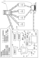
- FIG. 1 is a diagram for explaining the configuration of a substrate processing apparatus management system according to the first embodiment.
- FIG. 2 is a block diagram for explaining the functional configuration of the substrate processing apparatus management system according to the first embodiment.
- FIG. 3 is a diagram for explaining a specific calculation example of the degree of divergence.
- FIG. 4 is a diagram for explaining a specific calculation example of an abnormality score.
- FIG. 5 is a flow chart showing an example of processing executed in each of the plurality of substrate processing apparatuses of FIG.
- FIG. 6 is a flow chart showing an example of processing executed in the information analysis apparatus of FIG.
- FIG. 7 is a flow chart showing an example of processing executed by the management apparatus of FIG.
- FIG. 8 is a diagram for explaining the functional configuration of a substrate processing apparatus management system according to the second embodiment.
- 9 is a diagram showing an example of a plurality of weights stored in the weight storage unit of FIG. 8.
- the substrate means a semiconductor substrate, a substrate for FPD (Flat Panel Display) such as a liquid crystal display device or an organic EL (Electro Luminescence) display device, an optical disk substrate, a magnetic disk substrate, a magneto-optical disk substrate, A photomask substrate, a ceramic substrate, a solar cell substrate, or the like.
- FPD Fluorescence Panel Display
- OLED Electro Luminescence
- FIG. 1 is a diagram for explaining the configuration of a substrate processing apparatus management system according to the first embodiment.
- a substrate processing apparatus management system 2 according to the present embodiment is mainly composed of an information analysis apparatus 3 and a management apparatus 4, and manages a plurality of (five in this example) substrate processing apparatuses 1. used for In the following description, when distinguishing the five substrate processing apparatuses 1 shown in FIG. 1, the five substrate processing apparatuses 1 are called substrate processing apparatuses 1A, 1B, 1C, 1D, and 1E, respectively. In this embodiment, substrate processing apparatuses 1A to 1E have the same configuration.
- the substrate processing apparatus 1A is a so-called batch-type substrate cleaning apparatus, and includes a processing tank 11, a substrate holding section 12, an elevating apparatus 13, and a cleaning liquid generating apparatus. 14, densitometer 20, transfer robot 30 and controller 40.
- the substrate processing apparatus 1A is provided with a display device, an audio output device, and an operation section (not shown) in addition to the plurality of components described above.
- the substrate holding part 12 is configured to be able to hold a plurality of substrates W.
- the processing bath 11 is configured to accommodate a plurality of substrates W held by the substrate holding part 12 .
- a cleaning liquid for cleaning the substrates W is stored in the processing bath 11 .
- the lifting device 13 supports the substrate holding portion 12 so as to be vertically movable, and moves the substrate holding portion 12 vertically under the control of the control device 40 .
- the lifting device 13 immerses the plurality of substrates W held by the substrate holder 12 in the cleaning liquid stored in the processing tank 11 and pulls up the plurality of substrates W immersed in the cleaning liquid from the processing tank 11. be able to.
- a plurality of substrates W are cleaned by being immersed in the cleaning liquid.
- the lifting device 13 is provided with a motor (not shown) as a power source for vertically moving the substrate holder 12 .
- the cleaning liquid generation device 14 includes a storage tank 14a and a stirring device (a bubbling device, etc.) (not shown).
- a chemical solution supply pipe 91, a pure water supply pipe 92, an additional chemical solution supply pipe 93 and a drain pipe 94 are connected to the storage tank 14a.
- Each of the plurality of pipes (91-94) is provided with a valve.
- Each valve is a control valve whose opening degree can be adjusted under the control of the control device 40 .
- the chemical solution supply pipe 91 guides the chemical solution supplied from the chemical solution supply system (not shown) to the storage tank 14a by opening the valve provided in the chemical solution supply pipe 91 .
- the flow rate (supply amount per unit time) of the chemical solution supplied to the storage tank 14 a through the chemical solution supply pipe 91 changes according to the opening degree of the valve provided on the chemical solution supply pipe 91 .
- the pure water supply pipe 92 guides pure water supplied from a pure water supply system (not shown) to the storage tank 14a by opening a valve provided in the pure water supply pipe 92 .
- the flow rate (supply amount per unit time) of pure water supplied to the storage tank 14 a through the pure water supply pipe 92 changes according to the opening of the valve provided in the pure water supply pipe 92 .
- FIG. BHF buffered hydrofluoric acid
- DHF dilute hydrofluoric acid
- hydrofluoric acid hydrochloric acid
- sulfuric acid nitric acid
- phosphoric acid acetic acid
- oxalic acid ammonia, or the like
- the additional chemical supply pipe 93 guides the chemical supplied from the chemical supply system (not shown) to the storage tank 14a by opening the valve provided in the chemical supply pipe 91 .
- the supply of the chemical solution to the storage tank 14a through the additional chemical solution supply pipe 93 will be described later.
- the liquid drain pipe 94 discharges part or all of the cleaning liquid stored in the cleaning liquid generating device 14 to the outside of the substrate processing apparatus 1A by opening a valve provided in the liquid drain pipe 94 .
- a liquid supply pipe 15 is further connected to the storage tank 14a.
- the liquid supply pipe 15 is provided so as to connect the processing tank 11 and the cleaning liquid generator 14 .
- a pump 16 and a valve 17 are also provided in the liquid supply pipe 15 .
- the valve 17 is a control valve whose opening can be adjusted under the control of the control device 40 . By opening the valve 17 while the pump 16 is in operation, the cleaning liquid stored in the storage tank 14 a is supplied into the processing bath 11 .
- the flow rate (supply amount per unit time) of the cleaning liquid supplied from the storage tank 14 a to the processing bath 11 changes according to the opening degree of the valve 17 .
- a liquid discharge pipe 18 is connected to the bottom of the processing tank 11 .
- a valve 19 is provided in the liquid discharge pipe 18 .
- the valve 19 is a control valve whose opening degree can be adjusted under the control of the control device 40 .
- By opening the valve 19 part of the cleaning liquid stored in the processing bath 11 is discharged from the substrate processing apparatus 1A through the liquid discharge pipe 18.
- FIG. The flow rate (amount of discharge per unit time) of the cleaning liquid discharged from the processing bath 11 changes according to the degree of opening of the valve 19 .
- the cleaning liquid is supplied from the cleaning liquid generator 14 to the processing tank 11 and the cleaning liquid inside the processing tank 11 is discharged through the liquid discharge pipe 18 .
- the densitometer 20 detects the chemical solution concentration in the cleaning liquid stored in the storage tank 14 a in response to a command from the control device 40 and gives the detection result to the control device 40 .
- the transport robot 30 transports a plurality of substrates W held by the substrate holding part 12 at a position above the processing bath 11 .
- the control device 40 is composed of, for example, a CPU (Central Processing Unit) and memory, and controls the operation of the lifting device 13, the operation of the transfer robot 30, the opening degrees of the valves 17 and 19, and the like.
- the memory of the control device 40 stores a first management program, which will be described later.
- the control device 40 supplies the cleaning liquid to the storage tank 14a so that the concentration of the cleaning liquid stored in the storage tank 14a is within a predetermined range. Feedback control of the amount of chemical solution applied. For example, when the chemical solution concentration of the cleaning solution detected by the concentration meter 20 is lower than a predetermined range, the controller 40 supplies additional chemical solution to the cleaning solution generating device 14 through the additional chemical solution supply pipe 93 from a chemical solution supply system (not shown). supply.
- control device 40 controls the substrate when a person enters a predetermined space inside the substrate processing apparatus 1A or when a predetermined detector (for example, the densitometer 20) provided in the substrate processing apparatus 1A does not function. It has an emergency stop function for stopping the operation of the processing device 1A.
- a predetermined detector for example, the densitometer 20
- Each substrate processing apparatus 1 is provided with a plurality of pieces of processing information indicating the operation or state of processing of substrates W in the substrate processing apparatus 1 as information for managing abnormalities in the substrate processing apparatus 1. . These pieces of processing information are transmitted from the controller 40 of each substrate processing apparatus 1 to the information analysis apparatus 3 of the substrate processing apparatus management system 2 at predetermined intervals, as indicated by the thick solid line arrows in FIG.
- the processing information transmitted from the substrate processing apparatus 1A to the information analysis apparatus 3 includes "a. chemical solution concentration”, “b. chemical solution supply amount”, and “c. concentration detection input signal”. , “d. Concentration detection output signal”, “e. Motor rotation speed”, “f. including “exhaust valve opening”.
- Chemical concentration indicates the chemical concentration of the cleaning liquid in the storage tank 14a detected by the densitometer 20.
- Chemical solution supply amount indicates the flow rate (supply amount per unit time) of the cleaning solution supplied from the chemical solution supply pipe 91 to the storage tank of the cleaning solution generating device 14 .
- Chemical solution supply amount can be detected by, for example, providing a flow meter in the chemical solution supply pipe 91 .
- the chemical concentration of the cleaning liquid is detected by commanding the densitometer 20 from the control device 40 to detect the concentration.
- “c. Density detection input signal” is a command signal for density detection given from the controller 40 to the densitometer 20 .
- “d. Concentration detection output signal” is a signal indicating the detection result of the chemical solution concentration output from the densitometer 20 in response to a command from the control device 40 .
- Motor rotation speed is the rotation speed of the motor provided in the lifting device 13, and can be calculated by detecting the rotation speed of the motor using, for example, a rotation speed sensor.
- Power supplied to motor is the amount of power supplied to the motor provided in the lifting device 13, and can be calculated by detecting the current supplied to the motor using an ammeter, for example.
- g. Additional amount of chemical solution is the amount of the chemical solution additionally supplied from the additional chemical solution supply pipe 93 to the storage tank 14a so that the concentration of the cleaning solution in the cleaning solution stored in the storage tank 14a is within a predetermined range. Indicates the supply amount per unit time. “g. Added amount of chemical solution” can be detected by, for example, providing a flow meter in the additional chemical solution supply pipe 93 . “h. chemical supply valve opening” indicates the opening of the valve provided in the chemical supply pipe 91 . “i. Opening of cleaning liquid drain valve” indicates the opening of the valve provided in the drain pipe 94 .
- the information analysis apparatus 3 is, for example, a server, and includes a CPU and a memory.
- the information analysis device 3 collects a plurality of processing information transmitted from each substrate processing device 1 .
- a plurality of combinations of two mutually different processing information are predetermined for a plurality of processing information transmitted from each substrate processing device 1 to the information analysis device 3 .
- the substrate processing apparatus 1 ideally operates according to a predetermined processing procedure (recipe).
- a predetermined invariant (invariant) relationship (hereinafter referred to as an invariant relationship) is maintained between the two pieces of processing information forming each combination.
- the information analysis device 3 calculates the degree of divergence between a plurality of combinations of actually collected processing information and a plurality of invariant relations predetermined for the plurality of processing information. Calculate as degrees. Further, the information analysis device 3 calculates the degree of abnormality of the substrate processing apparatus 1 as an abnormality score based on the plurality of degrees of divergence that have been calculated. A specific example of the method of calculating the anomaly score will be described later.
- the information analysis device 3 transmits the calculated abnormality score to each substrate processing device 1, as indicated by the thick dashed-dotted arrow in FIG. Transmission of the anomaly score is performed each time an anomaly score is calculated by the information analysis device 3 . At this time, each substrate processing apparatus 1 stores the abnormality score transmitted from the information analysis apparatus 3 .
- the information analysis device 3 also determines whether or not the abnormality score exceeds a predetermined first threshold for each substrate processing device 1 . When the abnormality score exceeds the first threshold, the information analysis device 3 sends an alarm to the substrate processing apparatus 1 corresponding to the abnormality score. In the example of FIG. 1, the information analysis device 3 sends an alarm to the substrate processing apparatuses 1D and 1E among the substrate processing apparatuses 1A to 1E, as indicated by the wavy dotted line arrows. At this time, an alarm is output in the substrate processing apparatuses 1D and 1E that have received the alarm.
- the abnormality score (degree of abnormality) is lower for items that do not require prompt response by maintenance workers, and higher for items that require prompt response by maintenance workers.
- a state in which the abnormality score is low includes a state in which all of the plurality of processing conditions fall within a range predicted to be normal from the invariant relationships corresponding to the plurality of combinations.
- a state with a high abnormality score is, for example, a state in which the temporal change in “a. chemical concentration” is significantly larger than the temporal change predicted based on the temporal change in “b. , referred to as the first abnormal state).
- the continuation of the first abnormal state causes defective processing of the substrate W, generation of harmful gas, and damage to components of the substrate processing apparatus 1 due to the inability to adjust the chemical concentration of the cleaning liquid.
- a state in which the abnormality score is high is, for example, a state in which the time from when the concentration detection command is given to the densitometer 20 to when the concentration of the chemical solution is output from the densitometer 20 is extremely long (hereinafter referred to as a second abnormal state). including.
- the continuation of the second abnormal state causes defective processing of the substrate W, generation of harmful gas, and damage to components of the substrate processing apparatus 1 due to inability to perform appropriate feedback control of the concentration of the chemical solution.
- a state with a high abnormality score includes, for example, a state in which "f. power supplied to the motor" is significantly larger than the predicted value (hereinafter referred to as a third abnormal state).
- a third abnormal state there is a high possibility that an unexpected load is acting on the motor. Therefore, the continuation of the third abnormal state causes failure of the operating parts including the motor, defective transport of the substrate W, and damage to the constituent parts of the substrate processing apparatus 1 .
- a state with a high abnormality score includes, for example, a state in which "g. Addition amount of chemical solution” fluctuates beyond the expected range (hereinafter referred to as a fourth abnormal state).
- a fourth abnormal state a state in which "g. Addition amount of chemical solution” fluctuates beyond the expected range.
- the fourth state it is difficult to keep the cleaning liquid concentration constant. Therefore, continuation of the fourth abnormal state causes processing failure of the substrate W.
- a state with a high abnormality score is, for example, when changes over time in "h. chemical supply valve opening" and “i. cleaning liquid discharge valve opening” are the same as “a. chemical concentration” and “b. chemical supply amount”. (hereinafter referred to as a fifth abnormal state).
- a state with a high abnormality score is, for example, when changes over time in "h. chemical supply valve opening” and “i. cleaning liquid discharge valve opening” are the same as “a. chemical concentration” and “b. chemical supply amount”.
- the management apparatus 4 is, for example, a personal computer, and includes a CPU and a memory.
- the management device 4 includes a display section 4a and an operation section 4b, and is used by an administrator who manages a plurality of substrate processing apparatuses 1.
- FIG. 1 A block diagram illustrating an exemplary computing environment in accordance with the present disclosure.
- a plurality of maintenance workers in charge of the plurality of substrate processing apparatuses 1 can easily grasp the degree of abnormality in the substrate processing apparatuses 1 under their charge by confirming the abnormality score transmitted from the information analysis device 3. be able to. Further, each maintenance worker can recognize that a serious abnormality has occurred in the substrate processing apparatus 1 by receiving the alarm in the substrate processing apparatus 1 under his/her charge.
- a survey request is sent to the management device 4 .
- the abnormal score is sent from one or a plurality of substrate processing apparatuses 1 (substrate processing apparatuses 1A, 1C, and 1E in this example) that have sent the investigation request to the management apparatus 4. sent.
- the management device 4 can easily and quickly determine the priority of investigation based on the abnormality score received together with the investigation request. can be done.
- the administrator can determine the order of priority for investigation based on a plurality of abnormality scores of substrate processing apparatuses 1A, 1C, and 1E for which investigation requests have been made.
- each investigation request received from one or a plurality of substrate processing apparatuses 1 is prioritized each time a detailed investigation of the substrate processing apparatus 1 corresponding to the investigation request is performed.
- FIG. 2 is a block diagram for explaining the functional configuration of the substrate processing apparatus management system 2 according to the first embodiment.
- the information analysis device 3 includes an information collection unit 31, a score calculation unit 32, a score transmission unit 33, and an alarm transmission unit .
- a second management program for managing a plurality of substrate processing apparatuses 1 is stored in the memory of the information analysis apparatus 3 .
- the components (31 to 34) of the information analysis device 3 in FIG. 2 are implemented by the CPU of the information analysis device 3 executing the second management program stored in the memory. Some or all of the components (31 to 34) of the information analysis device 3 may be realized by hardware such as electronic circuits.
- the management device 4 also includes a request reception unit 41 , a score acquisition unit 42 and a score presentation unit 43 .
- a memory of the management device 4 stores a third management program for managing the plurality of substrate processing apparatuses 1 .
- the components (41 to 43) of the management device 4 in FIG. 2 are implemented by the CPU of the management device 4 executing the third management program stored in the memory. Some or all of the components (41 to 43) of the management device 4 may be realized by hardware such as electronic circuits.
- a plurality of pieces of processing information are transmitted from each of the plurality of substrate processing apparatuses 1 to the information analysis apparatus 3 at predetermined intervals (see thick solid line arrows in FIG. 2).
- the information collection unit 31 of the information analysis device 3 collects a plurality of pieces of processing information transmitted from each substrate processing apparatus 1 and gives the information to the score calculation unit 32 .
- the score calculation unit 32 of the information analysis device 3 calculates the abnormality score of the substrate processing apparatus 1 based on a plurality of pieces of processing information corresponding to each substrate processing apparatus 1, and transmits the calculated abnormality score to the score transmission unit 33 and an alarm. It is given to the transmission unit 34 .
- the score transmission unit 33 of the information analysis device 3 transmits the abnormality score calculated by the score calculation unit 32 to the substrate processing apparatus 1 corresponding to the abnormality score (see the thick dashed-dotted arrow in FIG. 2).
- the abnormality score transmitted from the score transmission unit 33 is stored in a state of being associated with time such as calculation time, transmission time, or reception time of the abnormality score.
- the alarm transmission unit 34 of the information analysis device 3 determines whether or not the abnormality score calculated for each substrate processing apparatus 1 exceeds the first threshold. Further, when the abnormality score exceeds the first threshold value, the alarm transmission unit 34 issues an alarm to the substrate processing apparatus 1 (the substrate processing apparatuses 1D and 1E in the example of FIG. 2) corresponding to the abnormality score. transmit (see wavy dotted arrow in FIG. 2).
- each substrate processing apparatus 1 an investigation request regarding an abnormality of the substrate processing apparatus 1 is sent to the management device 4 based on the operation by the maintenance worker. Also, the abnormality score stored in the substrate processing apparatus 1 is transmitted to the management apparatus 4 .
- the request reception unit 41 of the management device 4 receives an investigation request transmitted from one or more substrate processing apparatuses 1 (the substrate processing apparatuses 1A, 1C, and 1E in the example of FIG. arrow).
- the score acquisition unit 42 of the management device 4 acquires an abnormality score transmitted together with an investigation request from one or a plurality of substrate processing apparatuses 1 (the substrate processing apparatuses 1A, 1C, and 1E in the example of FIG. 2). (see dotted arrow).
- the score presentation unit 43 of the management device 4 causes the display unit 4a to display each of the one or more abnormality scores acquired by the score acquisition unit 42 in association with the substrate processing apparatus 1 corresponding to the abnormality score.
- the abnormality scores of the substrate processing apparatuses 1A, 1C, and 1E requested for investigation are "264,” “210,” and “322.” This allows the administrator to easily grasp the degree of abnormality in the substrate processing apparatuses 1E, 1A, and 1C. Also, it can be understood that the administrator should proceed with the detailed investigation in order of the substrate processing apparatuses 1E, 1A, and 1C.
- the score presenting unit 43 determines the order of priority of investigation based on the abnormality scores.
- the priority order may be displayed on the display unit 4a.
- FIG. 3 is a diagram for explaining a specific calculation example of the degree of divergence.
- a calculation example of the degree of divergence corresponding to the combination of "e. motor rotation speed” and “f. power supply to motor” in FIG. 1 will be described.
- the data of "e. Motor rotation speed” will be referred to as “e” data
- the data of "f. Power supply to motor” will be referred to as "f” data.
- ideal "e” data and "f” data are obtained, for example, based on a plurality of pieces of processing information transmitted from each substrate processing apparatus 1 when each substrate processing apparatus 1 is actually operating normally. be done.
- the ideal 'e' data and 'f' data may be generated by simulation or the like.
- the score calculator 32 predicts the "f” data based on pre-stored correlation information. Also, when the actual "f” data is collected, the score calculator 32 predicts the "e” data based on pre-stored correlation information.
- the graph at the bottom of FIG. 3 shows an example of temporal changes in the "e” data and the "f” data predicted based on the correlation information. In the lower graph of FIG. 3, predicted “e” data and “f” data are indicated by solid lines, and actually collected “e” data and "f” data are indicated by dotted lines.
- the actual "e” data and the predicted “e” data match or nearly match.
- the actual "f” data and the predicted “f” data will match or nearly match.
- an abnormality occurs in the substrate processing apparatus 1
- the degree of this divergence is considered to increase as the degree of abnormality occurring in the substrate processing apparatus 1 increases, and to decrease as the degree of abnormality occurring in the substrate processing apparatus 1 decreases.
- the difference value between the actually collected processing information data and the predicted processing information data is calculated as the degree of divergence.
- the score calculation unit 32 calculates the difference value between the actual "e” data and the predicted “e” data as the degree of divergence when calculating the degree of divergence at a certain time.
- the score calculation unit 32 also calculates the difference value between the actual "f" data and the predicted "f" data as the degree of divergence.
- FIG. 4 is a diagram for explaining a specific calculation example of an anomaly score.
- the score calculation unit 32 calculates the degree of divergence for all combinations of pieces of processing information.
- FIG. 4 shows a plurality of divergence degrees calculated for all combinations of a plurality of pieces of processing information.
- the score calculation unit 32 calculates the sum of the calculated plurality of deviation degrees as an abnormality score.
- FIG. 5 is a flow chart showing an example of processing executed in each of the plurality of substrate processing apparatuses 1 of FIG. A series of processes shown in FIG. 5 are started when each substrate processing apparatus 1 is powered on and the CPU of the control device 40 executes the first management program.
- the control device 40 transmits a plurality of pieces of processing information acquired inside the substrate processing apparatus 1 to the information analysis device 3 at predetermined intervals (step S10).
- the process of transmitting a plurality of pieces of processing information, which is started in step S10, is repeated at a predetermined cycle until the power of the substrate processing apparatus 1 is turned off.
- the control device 40 may store the transmitted pieces of processing information in association with their transmission times.
- control device 40 determines whether or not an abnormality score has been received from the information analysis device 3 (step S11). When the control device 40 does not receive the abnormality score, the control device 40 proceeds to the processing of step S13, which will be described later. On the other hand, when receiving an anomaly score, the control device 40 stores the received anomaly score in association with the reception time (step S12).
- control device 40 determines whether or not an alarm has been received from the information analysis device 3 (step S13). When the control device 40 does not receive the warning, the control device 40 proceeds to the processing of step S15, which will be described later. On the other hand, when receiving the alarm, the control device 40 outputs the alarm from the display device or the audio output device of the substrate processing apparatus 1 (step S14). The processes of steps S11 and S12 may be performed after the process of step S14.
- the control device 40 determines whether or not it has received a command to send an investigation request to the management device 4 (step S15).
- a command to transmit an investigation request is given to the control device 40 by, for example, a maintenance worker operating the operation unit of the substrate processing apparatus 1 .
- the control device 40 proceeds to the processing of step S17, which will be described later.
- the control device 40 transmits the investigation request and the abnormality score stored at the time closest to the current time to the management device 4 (step S16).
- the control device 40 may transmit to the management device 4 a plurality of abnormality scores stored up to a predetermined time (for example, several hours) before the current time, along with their reception times.
- control device 40 determines whether or not a work instruction to perform a specific work on the substrate processing apparatus 1 has been received from the management device 4 (step S17). When the control device 40 does not receive the work instruction, the process proceeds to step S19, which will be described later. On the other hand, when the work instruction is received, the control device 40 presents the received work instruction to the maintenance worker using, for example, a display device provided in the substrate processing apparatus 1 (step S18).
- control device 40 determines whether or not it has received an end command to stop the operation of the substrate processing apparatus 1 (step S19). If the control device 40 does not receive the end command, the process proceeds to step S11. On the other hand, when the control device 40 receives the end command, it ends the series of processes.
- FIG. 6 is a flow chart showing an example of processing executed in the information analysis apparatus 3 of FIG. A series of processes shown in FIG. 6 are started when the power of the information analysis device 3 is turned on and the CPU of the information analysis device 3 executes the second management program.
- the information collecting unit 31 in FIG. 2 starts collecting a plurality of pieces of processing information transmitted from each of the plurality of substrate processing apparatuses 1 (step S20).
- the process of collecting a plurality of pieces of processing information started in step S20 is repeated at a predetermined cycle until the power of the information analysis device 3 is turned off.
- the score calculation unit 32 in FIG. 2 selects one substrate processing apparatus 1 for which no abnormality score has been calculated from among the one or a plurality of substrate processing apparatuses 1 for which a plurality of pieces of processing information have been collected in the process of step S20. (step S21).
- the score calculation unit 32 calculates a plurality of deviation degrees from a plurality of pieces of collected processing information for the selected substrate processing apparatus 1 (step S22). Further, the score calculation unit 32 calculates the abnormality score of one substrate processing apparatus 1 based on the plurality of calculated degrees of deviation, and transmits the calculated abnormality score to the one substrate processing apparatus 1 (step S23). ).
- the alarm transmission unit 34 in FIG. 2 determines whether or not the abnormality score calculated in step S23 exceeds the first threshold (step S24). If the abnormality score does not exceed the first threshold value, the alarm transmission unit 34 proceeds to the process of step S26, which will be described later. On the other hand, when the abnormality score exceeds the first threshold value, the alarm transmission unit 34 transmits an alarm to one substrate processing apparatus 1 (step S25).
- the score calculation unit 32 determines whether or not there is a substrate processing apparatus 1 for which a plurality of pieces of processing information have been collected and for which an abnormality score has not been calculated (step S26). If there is a substrate processing apparatus 1 for which an abnormality score has not been calculated, the score calculation unit 32 proceeds to the process of step S21. On the other hand, if there is no substrate processing apparatus 1 for which an abnormality score has not been calculated, the score calculation unit 32 determines whether or not an end command to stop the operation of the information analysis apparatus 3 has been received (step S27). If the score calculation unit 32 does not receive the end command, the process proceeds to step S21. On the other hand, the score calculation unit 32 ends the series of processes when receiving the end command.
- FIG. 7 is a flowchart showing an example of processes executed in the management apparatus 4 of FIG. A series of processes shown in FIG. 7 are started when the management device 4 is powered on and the CPU of the management device 4 executes the third management program.
- the request receiving unit 41 in FIG. 2 determines whether or not a survey request has been received from at least one substrate processing apparatus 1 among the plurality of substrate processing apparatuses 1 (step S30). If the request receiving unit 41 does not receive a survey request, the process proceeds to step S33, which will be described later. On the other hand, when receiving an investigation request from at least one substrate processing apparatus 1, the request reception unit 41 accepts the received investigation request (step S31).
- the substrate processing apparatus 1 transmits an investigation request to the management apparatus 4, the substrate processing apparatus 1 transmits the abnormality score to the management apparatus 4 together with the investigation request.
- the score acquiring unit 42 in FIG. 2 receives and acquires the abnormality score transmitted together with the investigation request (step S32).
- the investigation request and abnormality score acquired at this time are stored in the memory of the management device 4 .
- the score presenting unit 43 in FIG. 2 determines whether or not it has received a command to start investigating the substrate processing apparatus 1 (step S33).
- a command to start investigation is given to the score presenting unit 43 by, for example, the administrator operating the operation unit 4b of the management device 4.
- FIG. If the score presentation unit 43 does not receive a command to start the survey, the process proceeds to step S30.
- the score presentation unit 43 determines whether or not there are a plurality of substrate processing apparatuses 1 to be investigated (step S34).
- the score presenting section 43 proceeds to the process of step S36, which will be described later.
- the score presenting unit 43 assigns the abnormality score of each substrate processing apparatus 1 to be investigated to the substrate processing apparatus 1. and display it on the display unit 4a (step S35).
- the score presentation unit 43 may display the abnormality score of the substrate processing apparatus 1 on the display unit 4a.
- the score presenting unit 43 may determine the order of priority of investigation based on a plurality of abnormality scores for a plurality of uninvestigated substrate processing apparatuses 1 for which an investigation request has been received. In this case, the score presentation unit 43 may display the determined priority on the display unit 4a.
- the CPU of the management device 4 performs the investigation processing for one substrate processing apparatus 1 among the one or more substrate processing apparatuses 1 to be investigated in response to the operation of the operation unit 4b by the administrator (step S36). Further, the CPU of the management device 4 transmits a work instruction to the maintenance worker to one substrate processing device 1 based on the result of the investigation process (step S37).
- the CPU of the management device 4 determines whether or not it has received an end command to stop the operation of the management device 4 (step S38). When the CPU of the management device 4 does not receive the end command, the process proceeds to step S30. On the other hand, the CPU of the management device 4 ends the series of processes when receiving the end command.
- step S36 the investigation request and abnormality score for the substrate processing apparatus 1 for which investigation processing has been performed are erased from the memory of the management device 4 when the investigation processing ends.
- step S36 the substrate processing apparatus 1 on which the investigation process has been performed is removed from the investigation target candidates.
- step S38 if there is a substrate processing apparatus 1 that has not been investigated among the one or more substrate processing apparatuses 1 to be investigated, the investigation request is stored in the memory of the management device 4. retained. Alternatively, in step S38, the substrate processing apparatus 1 that has been targeted for investigation and has not undergone the investigation process remains as a candidate for investigation.
- the two or more substrate processing devices 1 requested for investigation is displayed on the display unit 4a as an abnormality score.
- the administrator can easily grasp the degree of abnormality of two or more substrate processing apparatuses 1 requested for investigation based on the displayed abnormality score.
- the anomaly score is calculated based on the invariant relationship between multiple pieces of processing information. Therefore, the administrator can easily and appropriately grasp the order of priority of investigation in a short time for a plurality of substrate processing apparatuses 1 for which an investigation request has been made.
- the abnormality score calculated by the information analysis apparatus 3 is transmitted to the substrate processing apparatus 1 corresponding to the abnormality score.
- an abnormality score corresponding to the substrate processing apparatus 1 is stored in chronological order. Thereby, the maintenance worker in charge of each substrate processing apparatus 1 can easily check the temporal change of the abnormality score stored in the substrate processing apparatus 1 .
- Second Embodiment Among the plurality of combinations of the plurality of pieces of processing information described above, there are combinations that should be particularly emphasized when grasping the degree of abnormality in the substrate processing apparatus 1 and combinations that do not need to be emphasized.
- the combination of “a. Chemical concentration” and “b.” it can be said that it is a highly related combination.
- the combination of "c. concentration detection input signal” and “d. concentration detection output signal” calculates the abnormality score in order to avoid the continuation of the second abnormal state. It can be said that it is a highly related combination.
- a combination of processing information that does not require consideration of the first to fifth abnormal states is a combination that has a low relationship in calculating the abnormality score.
- the degree of divergence is the difference value between actually collected processing information data and predicted processing information data. Therefore, the degree of divergence calculated in the above-described embodiment does not take into account multiple types of abnormal states of the substrate processing apparatus 1 that should be emphasized when calculating the abnormality score. Therefore, a substrate processing apparatus management system according to the second embodiment has the following configuration.
- FIG. 8 is a diagram for explaining the functional configuration of a substrate processing apparatus management system according to the second embodiment.
- the information analysis device 3 has, as a functional unit, in addition to the components (31 to 34) described in the first embodiment, , a weight storage unit 39 is included.
- the weight storage unit 39 is realized by executing the second management program stored in the memory by the CPU of the information analysis device 3 according to the second embodiment.
- the weight storage unit 39 may be realized by hardware such as an electronic circuit.
- the weight storage unit 39 stores a plurality of weights respectively corresponding to a plurality of combinations of a plurality of pieces of processing information.
- FIG. 9 is a diagram showing an example of multiple weights stored in the weight storage unit 39 of FIG.
- six abnormality levels from “first level” to “sixth level” are set for a plurality of types of abnormal states that can occur in the substrate processing apparatus 1.
- FIG. The six abnormal levels are "first level”, “second level”, “third level”, “fourth level”, “fifth level” and “sixth level” in order of increasing degree of abnormality. and
- a weight having a magnitude corresponding to the abnormality level of the abnormal state is assigned to a combination of processing information highly relevant to each abnormal state.
- the highest “sixth level” is set for the fifth abnormal state.
- Chemical solution concentration “b. Chemical solution supply amount”, “h. Chemical solution supply valve opening” and “i. A weight of "6" is assigned to combinations between (8 combinations).
- the second highest “fifth level” is set for the first abnormal state.
- a weight of "5" is assigned to a combination (two combinations) of "a. chemical concentration” and “b. chemical supply amount” that are highly relevant to the first abnormal state.
- the third highest “fourth level” is set for the third abnormal state.
- a weight of "4" is assigned to the mutual combination (two combinations) of "e. motor rotation speed” and “f. power supplied to the motor” that are highly relevant to the third abnormal state.
- the fourth highest “third level” is set for the second abnormal state.
- a weight of "3" is assigned to the combination (two combinations) of "c. concentration detection input signal” and “d. concentration detection output signal” that are highly related to the second abnormal state.
- the fifth highest “second level” is set for the fourth abnormal state.
- the combination (four combinations) of "a. Chemical concentration”, “b. Chemical supply amount” and “g. ” is assigned.
- the lowest “first level” is set for the abnormal states other than the first to fifth abnormal states. Then, a weight of "1" is assigned to a plurality of combinations of a plurality of pieces of processing information with low relevance for a plurality of abnormal states including the first to fifth abnormal states.
- the score calculation unit 32 in FIG. 8 calculates the calculated difference value and the weight assigned to the combination for each combination of the plurality of pieces of processing information based on the plurality of weights stored in the weight storage unit 39.
- the multiplied value is calculated as the degree of divergence.
- the score calculation unit 32 in FIG. 8 calculates the sum of the calculated plurality of deviation degrees as an abnormality score.
- the abnormality score is calculated based on the deviation including the weighting amount according to the abnormality level.
- the administrator of the plurality of substrate processing apparatuses 1 can more appropriately grasp the degree of abnormality of each substrate processing apparatus 1 by referring to the calculated abnormality score.
- the information collection unit 31 integrates and resets the collected processing information every time a predetermined time elapses. You can repeat. Further, the information collecting section 31 may provide the score calculating section 32 with the processing information accumulated up to immediately before being reset every time a predetermined period of time elapses. In this case, the score calculation unit 32 calculates an abnormality score based on the accumulated plural pieces of processing information. In this case, it is possible to reduce the influence of noise or the like that occurs when each piece of processing information is collected on the abnormality score.
- a series of processes performed by the information analysis device 3 may be performed by the management device 4 . Also, a series of processes performed by the information analysis device 3 may be performed by any one of the plurality of substrate processing apparatuses 1 . In this case, the information analysis device 3 becomes unnecessary.
- the information analysis apparatus 3 receives the investigation requests from the plurality of substrate processing apparatuses 1, and detects the received investigation request and the abnormality corresponding to the investigation request. You may transmit a score to the management apparatus 4.
- FIG. 1 the information analysis apparatus 3 receives the investigation requests from the plurality of substrate processing apparatuses 1, and detects the received investigation request and the abnormality corresponding to the investigation request. You may transmit a score to the management apparatus 4.
- the abnormality score does not have to be transmitted from the information analysis apparatus 3 to the plurality of substrate processing apparatuses 1 .
- the management device 4 that has received an investigation request from one of the plurality of substrate processing apparatuses 1 may acquire the abnormality score of the substrate processing apparatus 1 that has received the investigation request from the information analysis device 3 .
- the plurality of substrate processing apparatuses 1A to 1E have the same configuration, but the present invention is not limited to this. Some or all of the plurality of substrate processing apparatuses 1A to 1E may have different configurations. At least one of the plurality of substrate processing apparatuses 1A to 1E may be a single substrate cleaning apparatus instead of a batch type substrate cleaning apparatus, and may have a configuration for performing processing other than cleaning processing.
- the plurality of processing information includes the temperature of the fluid supplied to the substrate W, the processing in which the substrate W is stored, At least one physical quantity selected from the temperature in the chamber, the pressure in the processing chamber in which the substrate W is accommodated, the pressure of the gas discharged from the processing chamber in which the substrate W is accommodated, and the movement speed of the substrate conveyed by the robot may be included. good.
- the plurality of pieces of processing information may include information relating to at least one of a driving pulse signal for driving the robot that transports the substrate W and an output signal of a detector provided in the robot that transports the substrate W.
- the score calculator 32 repeatedly accumulates and resets the abnormality score each time a predetermined time elapses, thereby calculating the integrated value of the abnormality score. may be further calculated.
- the alarm transmission unit 34 may determine whether or not the integrated value of the abnormality score exceeds a predetermined second threshold. Further, when the integrated value of the abnormality score exceeds the second threshold value, the alarm transmission unit 34 may transmit an alarm to the substrate processing apparatus 1 corresponding to the integrated value of the abnormality score. In this case, the maintenance worker of each substrate processing apparatus 1 can grasp with higher accuracy the occurrence of an abnormality in the substrate processing apparatus 1 that he or she is in charge of.
- the substrate processing apparatuses 1 and 1A to 1E are examples of a plurality of substrate processing apparatuses
- the substrate processing apparatus management system 2 is an example of a substrate processing apparatus management system
- the information collection unit 31 collects information.
- the score calculation unit 32 is an example of the score calculation unit
- the request reception unit 41 is an example of the request reception unit.
- the score acquiring unit 42 is an example of a score acquiring unit
- the score presenting unit 43 is an example of a priority presenting unit
- the plurality of abnormality scores of the plurality of substrate processing apparatuses 1 and the priority of investigation are priority information.
- the score transmission unit 33 is an example of a score transmission unit
- the alarm transmission unit 34 is an example of an alarm transmission unit
- the information analysis device 3 is an example of an information analysis device.
Abstract
Dans ce système de gestion de dispositifs de traitement de substrat, une pluralité d'éléments d'informations de traitement indiquant une opération ou un état associé au traitement d'un substrat sont collectés auprès de chaque dispositif parmi une pluralité de dispositifs de traitement de substrat. En ce qui concerne chaque dispositif de traitement de substrat, un degré d'anomalie dans le dispositif de traitement de substrat est calculé en tant que score d'anomalie, sur la base d'une relation invariante entre la pluralité d'éléments d'informations de traitement et la pluralité d'éléments d'informations de traitement collectés auprès du dispositif de traitement de substrat. Dans un dispositif de gestion, une demande d'investigation concernant une anomalie est reçue en provenance de chaque dispositif de traitement de substrat. Lorsqu'au moins deux demandes d'investigation ont été reçues, les scores d'anomalie pour les dispositifs de traitement de substrat correspondant aux demandes d'investigation sont acquis. Sur la base d'une pluralité de scores d'anomalie acquis, des informations d'ordre de priorité concernant un ordre de priorité dans lequel il faut répondre aux deux demandes d'investigation ou plus sont présentées à un responsable.
Applications Claiming Priority (2)
| Application Number | Priority Date | Filing Date | Title |
|---|---|---|---|
| JP2022-002650 | 2022-01-11 | ||
| JP2022002650A JP2023102218A (ja) | 2022-01-11 | 2022-01-11 | 基板処理装置管理システム、基板処理装置管理方法および基板処理装置管理プログラム |
Publications (1)
| Publication Number | Publication Date |
|---|---|
| WO2023135904A1 true WO2023135904A1 (fr) | 2023-07-20 |
Family
ID=87278769
Family Applications (1)
| Application Number | Title | Priority Date | Filing Date |
|---|---|---|---|
| PCT/JP2022/040548 WO2023135904A1 (fr) | 2022-01-11 | 2022-10-28 | Système de gestion de dispositifs de traitement de substrat, procédé de gestion de dispositifs de traitement de substrat et programme de gestion de dispositifs de traitement de substrat |
Country Status (3)
| Country | Link |
|---|---|
| JP (1) | JP2023102218A (fr) |
| TW (1) | TW202345203A (fr) |
| WO (1) | WO2023135904A1 (fr) |
Citations (4)
| Publication number | Priority date | Publication date | Assignee | Title |
|---|---|---|---|---|
| JPH1115518A (ja) * | 1997-06-23 | 1999-01-22 | Hitachi Ltd | 電子回路基板・装置の故障診断方式 |
| JP2005346482A (ja) * | 2004-06-03 | 2005-12-15 | Matsushita Electric Ind Co Ltd | 生産指示計画作成システムおよび記録媒体 |
| JP2021168364A (ja) * | 2020-04-13 | 2021-10-21 | キヤノン株式会社 | 情報処理装置、検出方法、プログラム、基板処理システム、及び物品の製造方法 |
| JP2022106238A (ja) * | 2021-01-06 | 2022-07-19 | オムロン株式会社 | 管理システム、管理装置、管理方法、及びプログラム |
-
2022
- 2022-01-11 JP JP2022002650A patent/JP2023102218A/ja active Pending
- 2022-10-28 WO PCT/JP2022/040548 patent/WO2023135904A1/fr unknown
- 2022-10-28 TW TW111140992A patent/TW202345203A/zh unknown
Patent Citations (4)
| Publication number | Priority date | Publication date | Assignee | Title |
|---|---|---|---|---|
| JPH1115518A (ja) * | 1997-06-23 | 1999-01-22 | Hitachi Ltd | 電子回路基板・装置の故障診断方式 |
| JP2005346482A (ja) * | 2004-06-03 | 2005-12-15 | Matsushita Electric Ind Co Ltd | 生産指示計画作成システムおよび記録媒体 |
| JP2021168364A (ja) * | 2020-04-13 | 2021-10-21 | キヤノン株式会社 | 情報処理装置、検出方法、プログラム、基板処理システム、及び物品の製造方法 |
| JP2022106238A (ja) * | 2021-01-06 | 2022-07-19 | オムロン株式会社 | 管理システム、管理装置、管理方法、及びプログラム |
Also Published As
| Publication number | Publication date |
|---|---|
| JP2023102218A (ja) | 2023-07-24 |
| TW202345203A (zh) | 2023-11-16 |
Similar Documents
| Publication | Publication Date | Title |
|---|---|---|
| US7254514B2 (en) | Method and system for predicting remaining life for motors featuring on-line insulation condition monitor | |
| KR100458885B1 (ko) | 회전 기계의 수명 예측 장치와 그 장치를 이용한 장비, 및회전 기계의 수명 예측 방법과 수리 타이밍 판정 방법 | |
| US6834256B2 (en) | Method and system for determining motor reliability | |
| Cheng et al. | Multivariate state estimation technique for remaining useful life prediction of electronic products | |
| WO2020235581A1 (fr) | Système de traitement de substrat | |
| US7957821B2 (en) | Systems and methods for statistical process control | |
| WO2017051562A1 (fr) | Système de diagnostic d'anomalie | |
| US20090089112A1 (en) | Service Resource Evaluation Method and System | |
| CN113252544A (zh) | 一种炼油装置腐蚀监测系统和方法 | |
| WO2023135904A1 (fr) | Système de gestion de dispositifs de traitement de substrat, procédé de gestion de dispositifs de traitement de substrat et programme de gestion de dispositifs de traitement de substrat | |
| US6821792B1 (en) | Method and apparatus for determining a sampling plan based on process and equipment state information | |
| US20060247803A1 (en) | Control system, control method, process system, and computer readable storage medium and computer program | |
| US6714884B2 (en) | Method and apparatus for providing communication between a defect source identifier and a tool data collection and control system | |
| JPWO2019043934A1 (ja) | 基板処理装置、基板処理装置の異常監視方法、及びプログラム | |
| WO2006016436A1 (fr) | Système de contrôle, méthode de contrôle,système de traitement, moyens de stockage pour ordinateur et programmation | |
| US20060235558A1 (en) | Method of scavenging intermediate formed by reaction of oxidoreductase with substrate | |
| JP2009283580A (ja) | 半導体装置の生産管理システム | |
| JPS6332650A (ja) | 製造設備の故障診断装置 | |
| JPH10223499A (ja) | 物品の製造方法、物品の製造システムおよび複数の加工処理装置の運用方法 | |
| WO2023140005A1 (fr) | Dispositif d'aide, procédé d'aide et programme d'aide | |
| WO2023135990A1 (fr) | Dispositif de détermination d'adéquation et procédé de détermination d'adéquation | |
| CN113887990A (zh) | 电气设备维修决策优化方法 | |
| WO2023162856A1 (fr) | Système de gestion d'appareil de traitement de substrat, appareil d'assistance, appareil de traitement de substrat, procédé de comparaison de performances inter-chambre et programme de comparaison de performances inter-chambre | |
| JP2009015654A (ja) | ワークの品質管理システムおよびワークの品質管理方法 | |
| JP7392373B2 (ja) | 水処理管理システム |
Legal Events
| Date | Code | Title | Description |
|---|---|---|---|
| 121 | Ep: the epo has been informed by wipo that ep was designated in this application |
Ref document number: 22920426 Country of ref document: EP Kind code of ref document: A1 |