WO2023135833A1 - 欠陥検出装置及び欠陥検出方法 - Google Patents
欠陥検出装置及び欠陥検出方法 Download PDFInfo
- Publication number
- WO2023135833A1 WO2023135833A1 PCT/JP2022/021526 JP2022021526W WO2023135833A1 WO 2023135833 A1 WO2023135833 A1 WO 2023135833A1 JP 2022021526 W JP2022021526 W JP 2022021526W WO 2023135833 A1 WO2023135833 A1 WO 2023135833A1
- Authority
- WO
- WIPO (PCT)
- Prior art keywords
- defect
- inspected
- axis
- images
- image
- Prior art date
- Legal status (The legal status is an assumption and is not a legal conclusion. Google has not performed a legal analysis and makes no representation as to the accuracy of the status listed.)
- Ceased
Links
Images










Classifications
-
- G—PHYSICS
- G01—MEASURING; TESTING
- G01N—INVESTIGATING OR ANALYSING MATERIALS BY DETERMINING THEIR CHEMICAL OR PHYSICAL PROPERTIES
- G01N21/00—Investigating or analysing materials by the use of optical means, i.e. using sub-millimetre waves, infrared, visible or ultraviolet light
- G01N21/84—Systems specially adapted for particular applications
- G01N21/88—Investigating the presence of flaws or contamination
- G01N21/89—Investigating the presence of flaws or contamination in moving material, e.g. running paper or textiles
- G01N21/892—Investigating the presence of flaws or contamination in moving material, e.g. running paper or textiles characterised by the flaw, defect or object feature examined
-
- G—PHYSICS
- G01—MEASURING; TESTING
- G01N—INVESTIGATING OR ANALYSING MATERIALS BY DETERMINING THEIR CHEMICAL OR PHYSICAL PROPERTIES
- G01N21/00—Investigating or analysing materials by the use of optical means, i.e. using sub-millimetre waves, infrared, visible or ultraviolet light
- G01N21/84—Systems specially adapted for particular applications
- G01N21/88—Investigating the presence of flaws or contamination
- G01N21/91—Investigating the presence of flaws or contamination using penetration of dyes, e.g. fluorescent ink
Definitions
- the present disclosure relates to a defect detection apparatus and a defect detection method for detecting defects on the surface of an object to be inspected that moves in a predetermined movement direction.
- magnetic particle testing which uses magnetic particles to inspect the surface of an object to be inspected
- a magnetic particle liquid containing magnetic particles is applied to the surface of the magnetized object to be inspected. Since the object to be inspected is magnetized, magnetic flux leaks from the opening or non-opening defects present on the surface of the object to be inspected, and the magnetic particles contained in the magnetic particle liquid are attracted to the defects.
- the magnetic particles are fluorescent magnetic particles, the magnetic particles are excited to emit light by irradiating the object to be inspected with ultraviolet light, and are visualized as magnetic particle patterns.
- the inspector visually observes the magnetic particle pattern in the dark room, and distinguishes between the magnetic particle pattern (defect pattern) caused by the defect and the magnetic particle pattern (pseudo pattern) caused by the accumulation of the magnetic particle liquid caused by the surface roughness other than the defect.
- the accuracy of the inspection largely depends on the skill of the inspector, and the shape and direction of the defects that occur vary widely, and the defect pattern may closely resemble the pseudo pattern, so the magnetic particle pattern is the defect pattern. It is difficult to determine whether or not
- automation of magnetic particle flaw detection is required.
- a uniform light (ultraviolet light in the case of fluorescent magnetic particles) is applied to the surface of the object to be inspected coated with magnetic particle liquid, and the operator visually observes the magnetic particle pattern, or the operator uses an imaging device Defects are detected by visually observing the captured image of the magnetic particle pattern captured in . Also, defects can be automatically detected by image processing the captured image.
- Patent Literature 1 proposes a magnetic particle flaw detector for magnetic particle flaw detection of a threaded portion of a steel pipe.
- the magnetic particle flaw detection apparatus described in Patent Document 1 has a configuration in which a plurality of two-dimensional imaging devices are arranged in parallel in the axial direction of the steel pipe, and a composite image of the entire threaded portion is generated while rotating the steel pipe in the circumferential direction.
- the angle of view (angle ⁇ 1) of each imaging device with respect to the axial direction of the steel pipe is the screw thread of the screw portion.
- Patent Literature 1 uses only the magnetic particle pattern imaged from a certain direction (the direction within the angle ⁇ 2 and the angle ⁇ ). Therefore, when a defect that is visible only when viewed from a specific direction is also a detection target, there is a problem that the defect cannot be detected when the above-mentioned fixed direction is different from the above-mentioned specific direction.
- An object of the present disclosure is to provide a defect detection apparatus and a defect detection method that can detect even defects that are visible only when viewed from a specific direction.
- a defect detection apparatus detects defects on the surface of an object to be inspected.
- the surface of the object to be inspected moves in a predetermined moving direction.
- the defect detection device includes an illuminator, a two-dimensional imaging device, and a defect detector.
- the illuminator irradiates the surface of the object to be inspected with light.
- a two-dimensional imaging machine has a visual axis in the normal direction of the surface of the object to be inspected.
- a two-dimensional imager receives light from a surface of an object to be inspected and generates a plurality of captured images having a two-dimensional area.
- the two-dimensional area is defined by a first axis in a direction corresponding to the moving direction, and a second axis in a direction corresponding to a direction orthogonal to the visual axis and the first axis.
- the defect detector detects defects on the surface of the object to be inspected based on the captured image.
- the defect detector is configured to perform the following processes. - A process of setting a plurality of capture areas arranged at different positions in the direction of the first axis in each of the captured images and extending in the direction of the second axis; ⁇ A plurality of connected images corresponding to a plurality of capture regions are generated by connecting the images included in each capture region of the captured images that are sequentially generated as the surface of the object to be inspected moves. and - A process of detecting a pixel group corresponding to a defect from a plurality of connected images
- the defect detection method detects defects on the surface of the object to be inspected.
- the surface of the object to be inspected moves in a predetermined movement direction.
- the defect detection method includes an illumination step, an imaging step, and a defect detection step.
- the illumination step the illuminator irradiates the surface of the object to be inspected with light.
- the imaging step a two-dimensional imaging machine having a visual axis in the direction normal to the surface of the object to be inspected sequentially receives light from the surface of the object to be inspected to generate a plurality of captured images having two-dimensional regions. .
- the two-dimensional area is defined by a first axis in a direction corresponding to the moving direction, and a second axis in a direction corresponding to a direction orthogonal to the visual axis and the first axis.
- the defect detector detects defects on the surface of the object to be inspected based on the captured image.
- the defect detection step includes a capture area setting step, a connected image generation step, and a detection step.
- the capturing area setting step a plurality of capturing areas arranged at different positions in the direction of the first axis and extending in the direction of the second axis are set in each captured image.
- the connected image generation step images included in each capture region of captured images sequentially generated along with movement of the surface of the object to be inspected are connected for each capture region to obtain a plurality of images corresponding to the plurality of capture regions. generates a concatenated image of
- the detection step a pixel group corresponding to a defect is detected from a plurality of connected images.
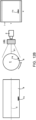
- FIG. 1A is a diagram schematically showing the schematic configuration of a defect detection apparatus according to an embodiment of the present disclosure, and is a front view of the defect detection apparatus as seen from the direction of the rotation axis of an object to be inspected.
- FIG. 1B is a side view of the defect detection device viewed from the direction indicated by arrow A in FIG. 1A.
- FIG. 1C is a diagram for explaining a connected image generation process executed by the defect detector shown in FIG. 1A.
- FIG. 1D is a diagram showing an example of a connected image.
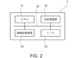
- FIG. 2 is a block diagram showing an example hardware configuration of a defect detector included in the defect detection apparatus.
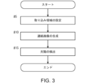
- FIG. 3 is a flow chart illustrating the processing performed by the defect detector.
- FIG. 1A is a diagram schematically showing the schematic configuration of a defect detection apparatus according to an embodiment of the present disclosure, and is a front view of the defect detection apparatus as seen from the direction of the rotation axis of an object to be inspected.
- FIG. 1B
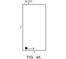
- FIG. 4A is a diagram schematically illustrating an example of a connected image generated when a simulated marker simulating a defect that is visualized when viewed from any direction is attached to an object to be inspected
- FIG. 1B is a diagram showing an example of a connected image CI 1 for a capture area TA 1 shown in FIG.
- FIG. 4B is a diagram showing an example of a connected image CI2 for the capture area TA2 shown in FIG. 1B.
- FIG. 4C is a diagram showing an example of a connected image CI3 for the capture area TA3 shown in FIG. 1B.
- FIG. 4D is a diagram showing an example of a connected image CI 4 for the capture area TA 4 shown in FIG. 1B.
- FIG. 1B is a diagram schematically illustrating an example of a connected image generated when a simulated marker simulating a defect that is visualized when viewed from any direction is attached to an object to be inspected
- FIG. 1B is a diagram showing an
- FIG. 4E is a diagram showing an example of a connected image CI 5 for the capture area TA 5 shown in FIG. 1B.
- FIG. 5A is a diagram schematically illustrating an example of a captured image generated when a defect that can be visualized when viewed from any direction exists on the surface of a cylindrical test object.
- FIG. 10 is a diagram showing a captured image I generated when F1 is positioned in capture area TA1 ;
- FIG. 5B is a diagram showing a captured image I generated when the defect F1 is located in the capture area TA3 .
- FIG. 5C is a diagram showing the captured image I generated when the defect F1 is located in the capture area TA5 .
- FIG. 6A is a diagram schematically illustrating an example of a captured image generated when a defect visible only when viewed from a specific direction exists on the surface of a cylindrical test object.
- FIG. 10 is a diagram showing a captured image I generated when F2 is positioned in capture area TA1 ;
- FIG. 6B is a diagram showing the captured image I generated when the defect F2 is located in the capture area TA3 .
- FIG. 6C is a diagram showing the captured image I generated when the defect F2 is located in the capture area TA5 .
- FIG. 7A is a diagram schematically illustrating an example of a connected image generated by rotating the inspection object having the same defect as that shown in FIG .
- FIG. 10 is a diagram showing a connected image CI 1 generated for .
- FIG. 7B is a diagram showing a connected image CI2 generated for the capture area TA2 .
- FIG. 7C shows a connected image CI3 generated for the capture area TA3 .
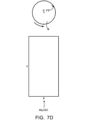
- FIG. 7D shows a connected image CI 4 generated for the capture area TA 4.
- FIG. 7E shows the connected image CI 5 generated for the capture area TA 5.
- FIG. 8A is a diagram schematically illustrating an example of a captured image generated for a substantially cylindrical inspected object having a convex portion, and is a captured image generated when the defect F3 is positioned in the capture area TA1 .
- FIG. 3 shows I.
- FIG. FIG. 8B is a diagram showing the captured image I when the defect F3 is located in the capture area TA3 .
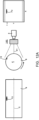
- FIG. 8C is a diagram showing the captured image I when the defect F3 is located in the capture area TA5 .
- FIG. 9 is a diagram for explaining capture areas set in the examples shown in FIGS. 8A to 8C.
- FIG. 10A is a diagram for schematically explaining an example of a connected image generated by rotating the inspection object having the same defect as that shown in FIG. 8A one round counterclockwise.
- FIG. 10 is a diagram showing a connected image CI 1 generated for .
- FIG. 10B is a diagram showing a connected image CI2 generated for the capture area TA2 .
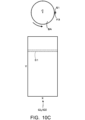
- FIG. 10C shows a connected image CI3 generated for the capture area TA3 .
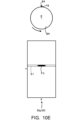
- FIG. 10D shows the connected image CI 4 generated for the capture area TA 4.
- FIG. 10E shows a connected image CI 5 generated for the capture area TA 5.
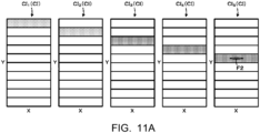
- FIG. 11A is a diagram schematically explaining a method of regenerating a connected image, and is a diagram showing a connected image CI before regeneration.
- FIG. 11B is a diagram showing the process of regenerating a connected image.
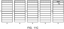
- FIG. 11C is a diagram showing a regenerated concatenated image.
- FIG. 12A is a diagram schematically illustrating an example of a captured image generated when a defect visible only when viewed from a specific direction exists on the surface of a cylindrical test object.
- FIG. 10 is a diagram showing a captured image I generated when F2 is positioned in capture area TA5 ;
- FIG. 12B is a diagram showing the captured image I when the defect F4 whose direction is different from that of the defect F2 is positioned in the capture area TA1 .
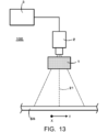
- FIG. 13 is a diagram schematically showing a state in which the defect detection apparatus according to the present embodiment is applied to a plate-shaped object to be inspected.
- a defect detection apparatus detects defects on the surface of an object to be inspected.
- the surface of the object to be inspected moves in a predetermined movement direction.
- the defect detection device includes an illuminator, a two-dimensional imaging device, and a defect detector.
- the illuminator irradiates the surface of the object to be inspected with light.
- a two-dimensional imaging machine has a visual axis in the normal direction of the surface of the object to be inspected.
- a two-dimensional imager receives light from a surface of an object to be inspected and generates a plurality of captured images having a two-dimensional area.
- the two-dimensional area is defined by a first axis in a direction corresponding to the moving direction, and a second axis in a direction corresponding to a direction orthogonal to the visual axis and the first axis.
- the defect detector detects defects on the surface of the object to be inspected based on the captured image.
- the defect detector is configured to perform the following processes. - A process of setting a plurality of capture areas arranged at different positions in the direction of the first axis in each of the captured images and extending in the direction of the second axis; ⁇ A plurality of connected images corresponding to a plurality of capture regions are generated by connecting the images included in each capture region of the captured images that are sequentially generated as the surface of the object to be inspected moves. and a process of detecting a pixel group corresponding to a defect from a plurality of connected images (first configuration)
- the two-dimensional imaging machine sequentially receives light over a two-dimensional area from the surface of the object to be inspected as the surface of the object to be inspected moves.
- the angle of view of the two-dimensional imaging device includes information captured from a plurality of different imaging directions.
- the defect detector first sets a plurality of capture areas in each captured image.
- the plurality of capture areas are arranged at different positions in the direction of the first axis, and each extend in the direction of the second axis (the axis in the direction corresponding to the direction orthogonal to the visual axis and the first axis).
- the plurality of capture areas are arranged at positions with different imaging directions in the direction corresponding to the movement direction of the surface of the object to be inspected.
- the defect detector corresponds to a plurality of capture areas by connecting images included in each capture area of captured images that are sequentially generated as the surface of the object to be inspected moves. Generate multiple concatenated images. As a result, one connected image is obtained by connecting the images included in the same captured area among the plurality of captured images. In other words, one connected image is obtained by connecting images captured from the same imaging direction among a plurality of captured images. Therefore, the plurality of connected images are images captured from different imaging directions, and include information when viewed from different imaging directions.
- the defect detector compares, for example, the density values of all pixels forming each connected image with a predetermined threshold to determine whether a pixel group corresponding to a defect exists in any of the plurality of connected images. It is possible to detect whether or not Therefore, according to the defect detection apparatus of the first configuration, even defects that are visible only when viewed from a specific direction can be detected.
- the object to be inspected is preferably a rotating body.
- the object to be inspected can be rotated around a predetermined rotation axis so that its circumferential direction is the moving direction of the surface of the object to be inspected.
- the two-dimensional imaging machine may sequentially generate a plurality of captured images as the object to be inspected rotates more than once (second configuration).
- Steel pipes, steel bars, wheels, axles, crankshafts, etc. can be exemplified as objects to be inspected that are rotating bodies.
- the object to be inspected is not limited to a rotating body, and may be, for example, a plate-like object such as a steel plate. If the object to be inspected is a plate-like object, the defect detection apparatus can also detect defects on the surface of the object to be inspected that moves (is transported) in its longitudinal direction.
- the illuminator irradiates the surface of the inspected object on which the magnetized fluorescent magnetic powder is scattered with ultraviolet light.
- the two-dimensional imaging device may receive light from the surface of the object to be inspected irradiated with ultraviolet light and generate a plurality of captured images (third configuration).
- the two-dimensional imaging device receives light emitted from the fluorescent magnetic particles adhering to the surface of the object to be inspected as the light from the surface of the object to be inspected.
- the defect detection device can be used for magnetic particle flaw detection.
- the defect detection device is not limited to magnetic particle flaw detection.
- the defect detection device emits visible light from the illuminator without scattering fluorescent magnetic powder on the surface of the object to be inspected, and the two-dimensional imaging machine emits light from the surface of the object to be inspected. It may be configured to receive reflected visible light.
- the defect detector generates a plurality of connected images such that the same part of the object to be inspected is displayed at the same position among the plurality of connected images (fourth configuration).
- the defect detection apparatus having the fourth configuration has the advantage of facilitating evaluation of the direction of the defect.
- the defect may be visualized only when viewed from a specific direction (fifth configuration).
- the defect detection device is not limited to this, and can be used to detect defects that are visualized when viewed from any of a plurality of different directions.
- a defect detection method detects defects on the surface of an object to be inspected.
- the surface of the object to be inspected moves in a predetermined moving direction.
- the defect detection method includes an illumination step, an imaging step, and a defect detection step.
- the illumination step the illuminator irradiates the surface of the object to be inspected with light.
- the imaging step a two-dimensional imaging machine having a visual axis in the direction normal to the surface of the object to be inspected sequentially receives light from the surface of the object to be inspected to generate a plurality of captured images having two-dimensional regions. .
- the two-dimensional area is defined by a first axis in a direction corresponding to the moving direction, and a second axis in a direction corresponding to a direction orthogonal to the visual axis and the first axis.
- the defect detector detects defects on the surface of the object to be inspected based on the captured image.
- the defect detection step includes a capture area setting step, a connected image generation step, and a detection step.
- the capturing area setting step a plurality of capturing areas arranged at different positions in the direction of the first axis and extending in the direction of the second axis are set in each captured image.
- the connected image generation step images included in each capture region of captured images sequentially generated along with movement of the surface of the object to be inspected are connected for each capture region to obtain a plurality of images corresponding to the plurality of capture regions. generates a concatenated image of
- a pixel group corresponding to a defect is detected from a plurality of connected images (sixth configuration).
- the two-dimensional imaging machine sequentially receives light over a two-dimensional area from the surface of the object to be inspected as the surface of the object to be inspected moves. Therefore, the angle of view of the two-dimensional imaging device includes information captured from a plurality of different imaging directions. Then, in the capturing area setting step, the defect detector first sets a plurality of capturing areas in each captured image.
- the plurality of capture areas are arranged at different positions in the direction of the first axis, and each extend in the direction of the second axis (the axis in the direction corresponding to the direction orthogonal to the visual axis and the first axis). In other words, the plurality of capture areas are arranged at positions with different imaging directions in the direction corresponding to the movement direction of the surface of the object to be inspected.
- the defect detector connects, for each captured image, images included in captured images sequentially generated as the surface of the object to be inspected moves. generates a plurality of concatenated images corresponding to the captured regions of .
- one connected image is obtained by connecting the images included in the same captured area among the plurality of captured images.
- one connected image is obtained by connecting images captured from the same imaging direction among a plurality of captured images. Therefore, the plurality of connected images are images captured from different imaging directions, and include information when viewed from different imaging directions.
- the defect detector compares the density values of all pixels constituting each connected image with a predetermined threshold value to determine whether a pixel corresponding to a defect is detected in one of the plurality of connected images. It is possible to detect whether groups exist or not. Therefore, according to the defect detection method of the sixth configuration, it is possible to detect even defects that are visible only when viewed from a specific direction.
- the object to be inspected is a rotating body that rotates about a predetermined rotation axis, and magnetic particle flaw detection is performed on the object to be inspected. Note that the present disclosure is not limited to magnetic particle flaw detection.
- FIG. 1A to 1D are diagrams schematically showing the schematic configuration of a defect detection device according to an embodiment of the present disclosure.
- FIG. 1A is a front view of the defect detection apparatus 100 viewed from the direction of the rotation axis C of the object S to be inspected.
- FIG. 1B is a side view of the defect detection apparatus 100 viewed from the direction indicated by arrow A in FIG. 1A.
- 1C and 1D are diagrams for explaining the process of generating a connected image executed by the defect detector 3 shown in FIG. 1A.
- illustration of the defect detector 3 is abbreviate
- FIG. 1B also shows the state of the capturing area setting process executed by the defect detector 3 .
- the defect detection apparatus 100 is an apparatus for detecting defects on the surface of an object S to be inspected.
- the subject S has a cylindrical shape.
- the object S to be inspected is a rotating body that rotates around the rotation axis C.
- the rotation axis C is the central axis of the object S to be inspected.
- the surface of the object S to be inspected moves in the circumferential direction of the object S to be inspected.
- the object S to be inspected is magnetized, and fluorescent magnetic powder is scattered on its surface.
- the defect detection apparatus 100 includes an illuminator 1 , a two-dimensional imaging device 2 and a defect detector 3 .
- the illuminator 1 is a device that irradiates the surface of the object S to be inspected with light.
- the illuminator 1 is arranged coaxially with the two-dimensional imaging device 2 and irradiates the surface of the object S to be inspected with ultraviolet light.
- a ring-type illumination device is used as the illumination device 1 .
- the illuminator 1 is arranged in a circular shape around the visual axis 21 of the two-dimensional imaging device 2 so as not to block the visual axis 21 of the two-dimensional imaging device 2 (the central axis of the imaging field of view 22 of the two-dimensional imaging device 2). are placed.
- the illuminator 1 includes, for example, multiple LED light sources that emit ultraviolet light.
- the illuminator 1 is configured to irradiate an area wider than the imaging field of view 22 of the two-dimensional imaging device 2 with ultraviolet light.
- a ring-shaped illuminator arranged coaxially with the two-dimensional imaging device 2 is used as the illuminator 1 .
- the illuminator 1 is not limited to this.
- various types of illuminators such as a line-type illuminator can be used.
- the illuminator 1 may irradiate the surface of the object S to be inspected with uniform light.
- the two-dimensional imaging device 2 has a visual axis 21 in the direction normal to the surface of the object S to be inspected, receives light from the surface of the object S to be inspected, and takes an image.
- the two-dimensional imaging device 2 captures an image by receiving light excited and emitted from fluorescent magnetic particles adhering to the surface of the object S to be inspected.
- the two-dimensional imaging device 2 generates a captured image I corresponding to the imaging visual field 22 by receiving light and capturing an image. As shown in FIG. 1C, the captured image I has a two-dimensional area.
- the two-dimensional area is defined by a first axis in a direction corresponding to the direction of movement of the surface of the object S to be inspected and a second axis in a direction corresponding to a direction orthogonal to the visual axis 21 and the first axis.
- the first axis is called the Y-axis
- the second axis is called the X-axis.
- the two-dimensional imaging device 2 for example, a monochrome or color area camera can be used.
- the area camera is composed of, for example, a 2048 ⁇ 2040 pixel CMOS or CCD.
- the two-dimensional imaging device 2 has an imaging field of view of 200 mm ⁇ 200 mm (resolution: 0.1 mm/pixel) when the distance to the object to be inspected S is 450 mm, for example, depending on the focal length and aperture of the lens used. Depth is set to 100 mm.
- the imaging field of view and the depth of field are not limited to these, and may be any suitable one depending on the type and surface properties of the object S to be inspected, the size of defects to be detected, the type of magnetic particles, etc. should be set to a value.
- the two-dimensional imaging machine 2 sequentially generates captured images I as the object S to be inspected rotates (rotates one round or more). That is, the two-dimensional imaging device 2 sequentially generates the captured images I as the surface of the object S to be inspected moves in the circumferential direction of the object S to be inspected.
- FIG. 1C shows an example in which n captured images I, that is, captured images I 1 to I n are generated.
- the defect detection apparatus 100 includes a rotation mechanism (not shown) that rotates the inspection object S around the rotation axis C. As shown in FIG.
- the two-dimensional imaging machine 2 can receive a rotation synchronization signal output from an encoder or the like included in the rotation mechanism.
- the two-dimensional imaging device 2 generates a captured image I each time the object S to be inspected rotates by a predetermined pitch (for example, 0.1 mm) in response to the rotation synchronization signal, and outputs the captured image I to the defect detector 3 .
- a predetermined pitch for example, 0.1 mm
- the defect detector 3 detects defects on the surface of the object S to be inspected based on the captured image I.
- the defect detector 3 is communicably connected to the two-dimensional imaging machine 2 .
- the defect detector 3 is, for example, a computer in which a program for executing various processes described later is installed.
- FIG. 2 is a block diagram showing an example of the hardware configuration of the defect detector 3.
- the defect detector 3 includes a CPU (Central Processing Unit) 31, a main storage device 32, an interface (I/F) 33, and an auxiliary storage device .
- the CPU 31 , main storage device 32 , interface 33 , and auxiliary storage device 34 are communicably connected to each other via a bus 35 .
- the main storage device 32 is a RAM (Random Access Memory) or the like that serves as a work area for the CPU 31 or the like.
- the interface 33 is connected to the two-dimensional imaging machine 2 (see FIGS. 1A and 1B) and a display (not shown).
- the auxiliary storage device 34 is an HDD (Hard Disk Drive) that stores various data, programs, and the like.
- the auxiliary storage device 34 may be a storage medium such as an SSD (Solid State Drive).
- the auxiliary storage device 34 stores a program for executing capture area setting processing, a program for executing connected image generation processing, and a program for executing defect detection processing.
- Various programs are loaded into the main storage device 32, the CPU 31 executes the programs, and the results are displayed on the display.
- FIG. 3 is a flow chart for explaining the processing executed by the defect detector 3. As shown in FIG. As shown in FIG. 3, the defect detector 3 performs a process (#5) for setting a capture area, a process (#10) for generating a connected image, and a process (#15) for detecting the presence or absence of a defect. configured to run.
- the defect detector 3 sets a plurality of capture areas TA corresponding to a plurality of positions defined in advance in the program in each captured image I (see FIG. 1B). ).
- the plurality of capturing areas TA are arranged at different positions in the Y-axis (first axis) direction and extend in the X-axis (second axis) direction.
- each capturing area TA has a size of 1 pixel in the Y-axis direction and 2048 pixels in the X-axis direction.
- five capture areas TA (TA 1 to TA 5 ) are set in each captured image I.
- each captured image I a plurality of capture areas TA (TA 1 to TA 5 ) are spaced apart in the Y-axis direction.
- the number and size of the capturing areas TA are not limited to the example of this embodiment, and can be set appropriately according to the direction of the defect to be detected.
- the defect detector 3 extracts (captures) the images included in the capture area TA of each captured image I, and connects them for each capture area TA.
- FIGS. 1C and 1D show, as an example, how the linking process is performed for the capture area TA3 .
- the two-dimensional imaging machine 2 sequentially generates captured images I 1 to I n as the object S to be inspected rotates one or more rounds.
- the defect detector 3 extracts an image included in the capture area TA 3 (TA 31 to TA 3n ) from each of the captured images I 1 to I n that are sequentially generated.
- the defect detector 3 Y Connect from the top to the bottom of the axis.
- the defect detector 3 also performs similar connection processing for the other capture areas TA 1 , TA 2 , TA 4 and TA 5 .
- the generation process of the captured image I by the two-dimensional imaging device 2 and the connection process of the image included in the capturing area TA of the captured image I by the defect detector 3 described above are performed when the object S to be inspected S rotates one or more times.
- a plurality of connected images CI corresponding to the plurality of capture areas TA are generated by repeating until the process is completed. That is, a connected image CI is generated for each capture area TA.
- FIG. 1D shows an example in which a connected image CI3 is generated for the capture area TA3 .
- the defect detector 3 After generating a plurality of connected images CI, the defect detector 3 executes processing for detecting defects from these connected images CI, as shown in step #15 of FIG. The defect detection process will be described below with reference to FIGS. 4A to 4E.
- FIGS. 4A to 4E show a connected image CI generated when a simulated marker M (see FIGS. 1A and 1B) simulating a defect visualized when viewed from any direction is attached to the inspected object S. It is a figure which illustrates typically the example of. Specifically, in FIGS. 4A to 4E , generation of the captured image I is started from the state shown in FIG .
- FIG. 1B is a diagram showing an example of a connected image CI generated by one rotation of the inspection object S counterclockwise in FIG. 1A. 4A shows an example of the connected image CI 1 for the capturing area TA 1 , FIG. 4B shows an example of the connected image CI 2 for the capturing area TA 2 , and FIG.
- 4C shows the connected image CI 3 for the capturing area TA 3.
- 4D shows an example of the connected image CI4 for the capturing area TA4
- FIG. 4E shows an example of the connected image CI5 for the capturing area TA5 .
- each of the connected images CI 1 to CI 5 is generated by connecting the images of the capturing area TA in the order in which they were extracted, so that the same part (simulated marker) of the subject S is generated.
- the position (position on the Y axis) of the site where M is attached differs among the connected images CI 1 to CI 5 .
- the defect detector 3 performs image processing on the generated multiple connected images CI, and detects pixel groups corresponding to defects from the multiple connected images CI. Specifically, for example, the defect detector 3 compares the density values (pixel values) of all pixels forming each connected image CI with a predetermined threshold value and binarizes them, thereby detecting defects. A group of pixels can be detected by distinguishing it from other groups of pixels. After performing the binarization process on each connected image CI, the defect detector 3 can perform noise removal such as removing a group of pixels having a small area (the number of pixels), if necessary.
- the defect detector 3 determines that a defect (flaw) exists in the object S to be inspected, and determines that the object S to be inspected S has a defect. may be displayed on the display device.
- the defect detector 3 can also cause the display to display the binarized connected image CI alone or together with the information indicating that the object S to be inspected has a defect.
- the inspector can visually check the connected image CI to confirm the defect.
- FIGS. 5A to 5C schematically illustrate an example of a captured image I generated when a defect F1 visible from any direction exists on the surface of a cylindrical inspection object S. It is a figure to do.
- the defect F1 is open on the surface of the object S to be inspected, and extends along the radial direction of the object S to be inspected in the depth direction.
- 5A shows a captured image I generated when the defect F1 is located in the capture area TA 1 (see FIG. 1B)
- FIG. 5B is a captured image I generated when the defect F1 is located in the capture area TA 3 (see FIG. 1B).
- FIG. 5C shows the captured image I when the defect F1 is located in the capturing area TA 5 (see FIG. 1B).
- the left figure is a side view of the inspected object S
- the middle figure is a front view of the inspected object S and the defect detection apparatus 100
- the right figure shows the captured image I.
- FIG. 1B the left figure is a side view
- FIGS. 5A to 5C As shown in FIGS. 5A to 5C, as the inspection object S rotates (counterclockwise rotation), the position of the defect F1 shifts from the position of the capture area TA1 (FIG. 5A) to the position of the capture area TA3. (FIG. 5B) to the location of the acquisition area TA 5 (FIG. 5C). Then, a captured image I in which the defect F1 is visualized is generated at each position.
- the defect F1 when the defect F1 is located in the capture area TA3 , the defect F1 is located on the visual axis 21 of the two-dimensional imaging machine 2. As shown in FIG. At this time, a captured image I is generated in which the pixel group corresponding to the defect F1 has the same shape and size as the actual object (actual magnetic particle pattern attracted to the defect F1). In contrast, when defect F1 is located in capture area TA1 , as shown in FIG. 5A, or when defect F1 is located in capture area TA5 , as shown in FIG. It is located away from the visual axis 21 of the imaging device 2 .
- the defect F1 since the defect F1 is imaged obliquely, the pixel group corresponding to the defect F1 becomes smaller in size than the actual object, the shape changes, and the resolution may become low. This change is remarkable if the angle of view of the two-dimensional imaging device 2 is large.
- FIGS. 6A to 6C schematically illustrate an example of a captured image I generated when a defect F2 visible only when viewed from a specific direction exists on the surface of a cylindrical inspection object S. It is a figure to do.
- FIG. 6A shows a captured image I generated when the defect F2 is located in the capture area TA 1 (see FIG. 1B)
- FIG. 6B is a captured image I generated when the defect F2 is located in the capture area TA 3 (see FIG. 1B).
- FIG. 6C shows the captured image I when the defect F2 is located in the capturing area TA 5 (see FIG. 1B).
- the left figure is a side view of the inspected object S
- the middle figure is a front view of the inspected object S and the defect detection apparatus 100
- the right figure shows the captured image I.
- FIG. in the right figures of FIGS. 6A and 6B, the position of the defect F2, which is not actually visualized but is supposed to be visualized, is indicated by a dotted line.
- the position of the defect F2 shifts from the position of the capture area TA1 (FIG. 6A) to the position of the capture area TA3. (FIG. 6B) to the location of the acquisition area TA 5 (FIG. 6C).
- the defect F2 is opened on the surface of the object S to be inspected, the depth direction is inclined from the radial direction of the object S to be inspected, and the depth direction extends along the surface of the object S to be inspected. Therefore, as shown in FIG.
- the imaging direction of the defect F2 is close to the depth direction of the defect F2, and the captured image I in which the defect F2 is visualized is generated.
- the angular difference between the imaging direction of the defect F2 and the depth direction of the defect F2 increases, and the defect F2 A captured image I in which is invisible is generated.
- any of the generated captured images I It is considered that the defect F2 is visualized in 1. Therefore, it is conceivable to adopt a method of detecting a pixel group corresponding to the defect F2 by performing image processing such as binarization on all of the plurality of captured images I. The same is true for defect F1 shown in FIGS. 5A to 5C.
- the defect detector 3 detects the image included in the capture area TA of each captured image I for each capture area TA.
- a configuration is adopted in which a plurality of connected images CI corresponding to a plurality of capturing areas TA are generated by connecting them.
- FIGS. 7A to 7E schematically illustrate an example of a connected image CI generated by rotating the inspected object S having the same defect F2 as shown in FIGS. 6A to 6C one round counterclockwise. It is a figure to do.
- the upper diagram shows the state where the defect F2 is located in the capture area TA1
- the lower diagram shows the connected image CI1 generated for the capture area TA1
- the upper diagram shows the state where the defect F2 is located in the capture area TA2
- the lower diagram shows the connected image CI2 generated for the capture area TA2 .
- the upper diagram shows the state where the defect F2 is located in the capture area TA3
- the lower diagram shows the connected image CI3 generated for the capture area TA3
- the upper diagram shows the state where the defect F2 is located in the capture area TA4
- the lower diagram shows the connected image CI4 generated for the capture area TA4
- the upper diagram shows the state where the defect F2 is located in the capture area TA5
- the lower diagram shows the connected image CI5 generated for the capture area TA5 .
- the defect F2 is not visualized in any of the connected images CI 1 to CI 4 respectively generated for the capture areas TA 1 to TA 4 .
- the defect F2 is visualized in the connected image CI5 generated for the capture area TA5 . Therefore, the defect detector 3 performs image processing on the plurality of generated connected images CI 1 to CI 5 , and among the plurality of connected images CI 1 to CI 5 , the pixel corresponding to the defect F2 is detected in the connected image CI 5. It is possible to detect the presence of groups.
- the resolution resolution in the Y-axis direction
- the imaging direction imaging direction in the Y-axis direction
- the binarization threshold value and the reference number of pixels for noise removal are the same in one connected image CI, the pixel group corresponding to the defect F2 can be detected with high accuracy.
- the defect F2 shown in FIGS. 6A to 6C was visible only when viewed from a specific direction due to the depth direction of the defect F2, but due to the shape of the object to be inspected, It is also possible that the defect is only visible when viewed from a particular direction.
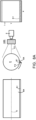
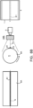
- FIGS. 8A to 8C are diagrams for schematically explaining an example of the captured image I generated for the substantially cylindrical inspection subject SA having the convex portion S1.
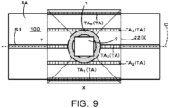
- FIG. 9 is a diagram for explaining the capturing area TA set in the examples shown in FIGS. 8A to 8C.
- FIGS. 8A to 8C the defect F3 exists on one side surface of the convex portion S1.
- FIG. 8A shows a captured image I generated when defect F3 is located in capture area TA 1 (see FIG. 9).
- FIG. 8B shows the captured image I when the defect F3 is located in the capture area TA 3 (see FIG. 9).
- FIG. 8C shows the captured image I when the defect F3 is located in the capturing area TA 5 (see FIG. 9).
- the left figure is a side view of the inspection object SA
- the middle figure is a front view of the inspection object SA and the defect detection apparatus 100
- the right figure shows the captured image I.
- FIG. In the right diagrams of FIGS. 8A to 8C dotted lines indicate the positions of the protrusions S1 that are assumed to be visualized, although they are not actually visualized.
- the position of the defect F3 shifts from the position of the capture area TA1 (FIG. 8A) to the position of the capture area TA3. (FIG. 8B) to the position of the capture area TA 5 (FIG. 8C).
- the defect F3 is located on the side surface of the convex portion S1 on the opposite side (left side) to the side facing the two-dimensional imaging machine 2, so it is not visualized. Further, as shown in FIG.
- the side surfaces of the convex portion S1 are positioned above and below, and the defect F3 is positioned on the side surface of the lower convex portion S1, so that it is not visualized.
- the defect F3 is located on the side surface of the convex portion S1 on the side facing the two-dimensional imaging machine 2 (right side), and therefore is visualized.
- FIGS. 10A to 10E schematically illustrate an example of a connected image CI generated by rotating the object SA having the same defect F3 as shown in FIGS. 8A to 8C counterclockwise one round. It is a figure to do.
- the upper diagram shows the state where the defect F3 is located in the capture area TA1
- the lower diagram shows the connected image CI1 generated for the capture area TA1
- the upper diagram shows the state where the defect F3 is located in the capture area TA2
- the lower diagram shows the connected image CI2 generated for the capture area TA2 .
- the upper diagram shows the state where the defect F3 is located in the capture area TA3
- the lower diagram shows the connected image CI3 generated for the capture area TA3
- the upper diagram shows the state where the defect F3 is located in the capture area TA4
- the lower diagram shows the connected image CI4 generated for the capture area TA4
- the upper diagram shows the state where the defect F3 is located in the capture area TA5
- the lower diagram shows the connected image CI5 generated for the capture area TA5 .
- the position of the convex portion S1 which is not actually visualized but is assumed to be visualized, is indicated by a dotted line.
- the defect F3 is not visualized in any of the connected images CI 1 to CI 4 respectively generated for the capturing areas TA 1 to TA 4 .
- the defect F3 is visualized in the connected image CI5 generated for the capture area TA5 . Therefore, the defect detector 3 performs image processing on the plurality of generated connected images CI 1 to CI 5 , and among the plurality of connected images CI 1 to CI 5 , the pixel corresponding to the defect F3 is detected in the connected image CI 5. It is possible to detect the presence of groups.
- the convex portion S1) of the object to be inspected SA is not displayed at the same position (the same position in the Y-axis direction) among the connected images CI (CI 1 to CI 5 ).
- the display position in each connected image CI is shifted in the Y-axis direction from the display positions in other connected images CI with respect to the same part of the object to be inspected.
- the images included in each captured area TA of the captured image I sequentially generated by the two-dimensional imaging device 2 are arranged in the order of extraction (the order in which the captured image I was generated) from the top to the bottom of the Y axis. This is because the connected image CI is generated by combining the images.
- the same part of the subject to be inspected may be the same among the plurality of concatenated images CI. (the same position in the Y-axis direction) to regenerate the connected image CI.
- FIGS. 11A to 11C are diagrams schematically explaining a method for regenerating the connected image CI. Specifically, FIGS. 11A to 11C are diagrams explaining a method of regenerating the connected image CI shown in FIGS. 7A to 7E.
- FIG. 11A is a view showing the concatenated image CI before regeneration (a view corresponding to the concatenated image CI shown in FIGS. 7A to 7E). 2) represents the part where the defect F2 exists.
- FIG. 11A shows how each connected image CI starts to be generated based on the state where the defect F2 is located in the capture area TA1 . The image is located at the top of the Y-axis.
- images corresponding to the portion where the defect F2 exists are displayed according to the amount of positional deviation (the amount of positional deviation in the Y-axis direction) of the capture areas TA 2 to TA 5 with respect to the capture area TA 1 . It will be shifted downward in the direction of the Y-axis.
- the amount of positional deviation of the images corresponding to the same part of the subject S is determined by the position of each capturing area TA set in the captured image I and the pitch (for example, 0.1 mm) for generating the captured image I. ) and can be obtained by Therefore, as shown in FIG. 11B, images (images indicated by dashed lines in FIG. 11B) corresponding to the positional deviation amounts of the images corresponding to the same part of the subject S in the connected images CI 2 to CI 5 are shown in FIG. Move downward in the direction of the Y-axis, as shown at 11C. As a result, it is possible to regenerate the connected image CI in which the image corresponding to the same part of the subject S is displayed at the same position (the same position in the Y-axis direction) among the plurality of connected images CI. be possible.
- the defect detection apparatus 100 of this embodiment has an advantage that it is easy to evaluate the direction of the defect F2.
- FIG. 12A and 12B are diagrams for schematically explaining an example of a captured image I generated when a defect visible only when viewed from a specific direction exists on the surface of a cylindrical inspection object S. is.
- FIG. 12A shows a captured image I produced when the same defect F2 shown in FIGS. 6A-6C is located in capture area TA 5 (see FIG. 1B).
- FIG. 12B shows the captured image I when the defect F4 whose direction is different from that of the defect F2 is located in the capturing area TA 1 (see FIG. 1B).
- the left figure is a side view of the inspected object S
- the middle figure is a front view of the inspected object S and the defect detection apparatus 100
- the right figure shows the captured image I.
- FIG. 12A shows a captured image I produced when the same defect F2 shown in FIGS. 6A-6C is located in capture area TA 5 (see FIG. 1B).
- FIG. 12B shows the captured image I when the defect F4 whose direction is different from that
- both the defect F2 and the defect F4 are defects that open on the surface of the object S to be inspected and extend along the surface of the object S to be inspected in the depth direction.
- the depth direction from the opening extends in the rotation direction (counterclockwise) of the object S to be inspected
- the depth direction from the opening of the defect F4 is opposite to the rotation direction of the object S to be inspected. extending in the direction That is, the directions of both defects F2 and F4 are different.
- Defect F2 shown in FIG. 12A is visible when located in uptake area TA5 . That is, the defect F2 is visible in the concatenated image CI5 .
- defect F4 shown in FIG. 12B is visible when located in capture area TA1 . That is, defect F4 is visualized in concatenated image CI1 .
- the regenerated connected images CI 1 and CI 5 are displayed as the connected images CI 1 and CI 5 , and the same position in the Y-axis direction is displayed between the connected images CI 1 and CI 5 .
- the object to be inspected is a rotating body that rotates about the predetermined rotation axis C
- the object to be inspected is not limited to a rotating body.
- FIG. 13 is a diagram schematically showing a state in which the defect detection apparatus 100 according to the present embodiment is applied to a plate-shaped object to be inspected SB.
- the defect detection apparatus 100 can also be applied when a plate-like object such as a steel plate moving (conveyed) in the longitudinal direction is the object to be inspected SB.
- the longitudinal direction is the movement direction of the surface of the object SB to be inspected.
- the imaging device 2 may sequentially generate the captured image I having a two-dimensional area.
- the two-dimensional area has a first axis (Y-axis) in a direction corresponding to the movement direction of the surface of the object to be inspected SB and a second axis in a direction perpendicular to the visual axis 21 and the Y-axis of the two-dimensional imaging device 2 .
- 2 axes (X-axis).
- the multiple capture areas TA are arranged at different positions in the Y-axis direction and extend in the X-axis direction. Further, the defect detector 3 connects the images included in the capture areas TA of the picked-up images I sequentially generated along with the movement of the object to be inspected SB for each capture area TA, thereby forming a plurality of capture areas TA. Generate a corresponding plurality of concatenated images CI. By using this connected image CI, it is possible to detect even defects that are visible only when viewed from a specific direction, as in the case of the body of revolution.
- the present disclosure is not limited to this, and without scattering fluorescent magnetic powder on the surface of the object to be inspected, the illuminator 1 irradiates visible light, and the two-dimensional imaging device 2 emits The light may be visible light reflected by the surface of the object to be inspected.
- Illuminator 2 Two-dimensional imaging device 21: Visual axis 3: Defect detector 100: Defect detector CI: Connected image S, SA, SB: Object to be inspected TA: Capture area I: Captured image
Landscapes
- Physics & Mathematics (AREA)
- Health & Medical Sciences (AREA)
- Life Sciences & Earth Sciences (AREA)
- Chemical & Material Sciences (AREA)
- Analytical Chemistry (AREA)
- Biochemistry (AREA)
- General Health & Medical Sciences (AREA)
- General Physics & Mathematics (AREA)
- Immunology (AREA)
- Pathology (AREA)
- Engineering & Computer Science (AREA)
- Textile Engineering (AREA)
- Investigating Materials By The Use Of Optical Means Adapted For Particular Applications (AREA)
Priority Applications (2)
| Application Number | Priority Date | Filing Date | Title |
|---|---|---|---|
| CN202280087903.0A CN118511070A (zh) | 2022-01-11 | 2022-05-26 | 缺陷检测装置和缺陷检测方法 |
| JP2023573823A JPWO2023135833A1 (https=) | 2022-01-11 | 2022-05-26 |
Applications Claiming Priority (2)
| Application Number | Priority Date | Filing Date | Title |
|---|---|---|---|
| JP2022002590 | 2022-01-11 | ||
| JP2022-002590 | 2022-01-11 |
Publications (1)
| Publication Number | Publication Date |
|---|---|
| WO2023135833A1 true WO2023135833A1 (ja) | 2023-07-20 |
Family
ID=87278747
Family Applications (1)
| Application Number | Title | Priority Date | Filing Date |
|---|---|---|---|
| PCT/JP2022/021526 Ceased WO2023135833A1 (ja) | 2022-01-11 | 2022-05-26 | 欠陥検出装置及び欠陥検出方法 |
Country Status (3)
| Country | Link |
|---|---|
| JP (1) | JPWO2023135833A1 (https=) |
| CN (1) | CN118511070A (https=) |
| WO (1) | WO2023135833A1 (https=) |
Cited By (1)
| Publication number | Priority date | Publication date | Assignee | Title |
|---|---|---|---|---|
| CN117665095A (zh) * | 2024-02-01 | 2024-03-08 | 潍坊市计量测试所 | 一种基于机器视觉的无缝钢管检测方法及系统 |
Citations (4)
| Publication number | Priority date | Publication date | Assignee | Title |
|---|---|---|---|---|
| US20120026319A1 (en) * | 2010-07-27 | 2012-02-02 | Pixart Imaging Inc. | Distance measuring system and distance measuring method |
| JP2016080517A (ja) * | 2014-10-17 | 2016-05-16 | セイコーインスツル株式会社 | 表面検査装置 |
| JP2021025878A (ja) * | 2019-08-05 | 2021-02-22 | 電子磁気工業株式会社 | 磁粉探傷装置、及び磁粉探傷方法 |
| JP2021139630A (ja) * | 2020-03-02 | 2021-09-16 | 日本製鉄株式会社 | 表面検査装置及び表面検査方法 |
-
2022
- 2022-05-26 WO PCT/JP2022/021526 patent/WO2023135833A1/ja not_active Ceased
- 2022-05-26 JP JP2023573823A patent/JPWO2023135833A1/ja active Pending
- 2022-05-26 CN CN202280087903.0A patent/CN118511070A/zh active Pending
Patent Citations (4)
| Publication number | Priority date | Publication date | Assignee | Title |
|---|---|---|---|---|
| US20120026319A1 (en) * | 2010-07-27 | 2012-02-02 | Pixart Imaging Inc. | Distance measuring system and distance measuring method |
| JP2016080517A (ja) * | 2014-10-17 | 2016-05-16 | セイコーインスツル株式会社 | 表面検査装置 |
| JP2021025878A (ja) * | 2019-08-05 | 2021-02-22 | 電子磁気工業株式会社 | 磁粉探傷装置、及び磁粉探傷方法 |
| JP2021139630A (ja) * | 2020-03-02 | 2021-09-16 | 日本製鉄株式会社 | 表面検査装置及び表面検査方法 |
Cited By (2)
| Publication number | Priority date | Publication date | Assignee | Title |
|---|---|---|---|---|
| CN117665095A (zh) * | 2024-02-01 | 2024-03-08 | 潍坊市计量测试所 | 一种基于机器视觉的无缝钢管检测方法及系统 |
| CN117665095B (zh) * | 2024-02-01 | 2024-04-19 | 潍坊市计量测试所 | 一种基于机器视觉的无缝钢管检测方法及系统 |
Also Published As
| Publication number | Publication date |
|---|---|
| CN118511070A (zh) | 2024-08-16 |
| JPWO2023135833A1 (https=) | 2023-07-20 |
Similar Documents
| Publication | Publication Date | Title |
|---|---|---|
| TWI626440B (zh) | 缺陷檢測裝置、缺陷檢測方法及程式產品 | |
| EP3203217B1 (en) | Inspection device and inspection method | |
| US10705029B2 (en) | Inspection apparatus and inspection method | |
| JP6922539B2 (ja) | 表面欠陥判定方法および表面欠陥検査装置 | |
| JP6646339B2 (ja) | 表面欠陥検出方法、表面欠陥検出装置、及び鋼材の製造方法 | |
| CN105849534A (zh) | 表面缺陷检测方法及表面缺陷检测装置 | |
| JP6079948B1 (ja) | 表面欠陥検出装置および表面欠陥検出方法 | |
| JP6635712B2 (ja) | 検査方法、検査装置、画像処理装置、プログラム及び記録媒体 | |
| EP3399302A1 (en) | Egg surface inspection apparatus | |
| WO2023135833A1 (ja) | 欠陥検出装置及び欠陥検出方法 | |
| JP6387909B2 (ja) | 表面欠陥検出方法、表面欠陥検出装置、及び鋼材の製造方法 | |
| JP2006234771A (ja) | 金属ロールの表面欠陥検査方法およびその装置 | |
| JPH11223610A (ja) | 表面欠陥探傷装置及び蛍光磁粉探傷方法 | |
| JP4739044B2 (ja) | 外観検査装置 | |
| JP2010014670A (ja) | 外観検査装置、外観検査方法、画像処理方法及びこれを利用した外観検査装置 | |
| JP2010038723A (ja) | 欠陥検査方法 | |
| JP7299388B2 (ja) | 鉄管外表面の欠陥判定装置 | |
| TWI493177B (zh) | 一種檢測具週期性結構光學薄膜的瑕疵檢測方法及其檢測裝置 | |
| JP3135075B2 (ja) | 外観検査方法およびその装置、磁気ヘッド検査方法およびその装置並びに磁気ヘッド製造設備 | |
| JP2010139434A (ja) | 異物とキズ痕との判別検査装置及び検査方法 | |
| WO2024166415A1 (ja) | 表面検査装置及び表面検査方法 | |
| JP2005092471A (ja) | 画像処理装置 | |
| EP4509823A1 (en) | Surface inspection device and surface inspection method | |
| JPWO2024166415A5 (https=) | ||
| WO2026074754A1 (ja) | 磁粉探傷装置及び磁粉探傷方法 |
Legal Events
| Date | Code | Title | Description |
|---|---|---|---|
| 121 | Ep: the epo has been informed by wipo that ep was designated in this application |
Ref document number: 22920358 Country of ref document: EP Kind code of ref document: A1 |
|
| ENP | Entry into the national phase |
Ref document number: 2023573823 Country of ref document: JP Kind code of ref document: A |
|
| WWE | Wipo information: entry into national phase |
Ref document number: 202280087903.0 Country of ref document: CN |
|
| WWE | Wipo information: entry into national phase |
Ref document number: 202417058565 Country of ref document: IN |
|
| NENP | Non-entry into the national phase |
Ref country code: DE |
|
| 122 | Ep: pct application non-entry in european phase |
Ref document number: 22920358 Country of ref document: EP Kind code of ref document: A1 |