WO2023135783A1 - 遠心送風機及び空気調和装置 - Google Patents
遠心送風機及び空気調和装置 Download PDFInfo
- Publication number
- WO2023135783A1 WO2023135783A1 PCT/JP2022/001294 JP2022001294W WO2023135783A1 WO 2023135783 A1 WO2023135783 A1 WO 2023135783A1 JP 2022001294 W JP2022001294 W JP 2022001294W WO 2023135783 A1 WO2023135783 A1 WO 2023135783A1
- Authority
- WO
- WIPO (PCT)
- Prior art keywords
- plate
- fan
- extension plate
- discharge port
- scroll casing
- Prior art date
- Legal status (The legal status is an assumption and is not a legal conclusion. Google has not performed a legal analysis and makes no representation as to the accuracy of the status listed.)
- Ceased
Links
Images





Classifications
-
- F—MECHANICAL ENGINEERING; LIGHTING; HEATING; WEAPONS; BLASTING
- F04—POSITIVE - DISPLACEMENT MACHINES FOR LIQUIDS; PUMPS FOR LIQUIDS OR ELASTIC FLUIDS
- F04D—NON-POSITIVE-DISPLACEMENT PUMPS
- F04D29/00—Details, component parts, or accessories
- F04D29/40—Casings; Connections of working fluid
- F04D29/42—Casings; Connections of working fluid for radial or helico-centrifugal pumps
- F04D29/4206—Casings; Connections of working fluid for radial or helico-centrifugal pumps especially adapted for elastic fluid pumps
- F04D29/422—Discharge tongues
-
- F—MECHANICAL ENGINEERING; LIGHTING; HEATING; WEAPONS; BLASTING
- F04—POSITIVE - DISPLACEMENT MACHINES FOR LIQUIDS; PUMPS FOR LIQUIDS OR ELASTIC FLUIDS
- F04D—NON-POSITIVE-DISPLACEMENT PUMPS
- F04D29/00—Details, component parts, or accessories
- F04D29/40—Casings; Connections of working fluid
- F04D29/42—Casings; Connections of working fluid for radial or helico-centrifugal pumps
- F04D29/4206—Casings; Connections of working fluid for radial or helico-centrifugal pumps especially adapted for elastic fluid pumps
- F04D29/4226—Fan casings
-
- F—MECHANICAL ENGINEERING; LIGHTING; HEATING; WEAPONS; BLASTING
- F04—POSITIVE - DISPLACEMENT MACHINES FOR LIQUIDS; PUMPS FOR LIQUIDS OR ELASTIC FLUIDS
- F04D—NON-POSITIVE-DISPLACEMENT PUMPS
- F04D17/00—Radial-flow pumps, e.g. centrifugal pumps; Helico-centrifugal pumps
- F04D17/08—Centrifugal pumps
- F04D17/10—Centrifugal pumps for compressing or evacuating
-
- F—MECHANICAL ENGINEERING; LIGHTING; HEATING; WEAPONS; BLASTING
- F24—HEATING; RANGES; VENTILATING
- F24F—AIR-CONDITIONING; AIR-HUMIDIFICATION; VENTILATION; USE OF AIR CURRENTS FOR SCREENING
- F24F1/00—Room units for air-conditioning, e.g. separate or self-contained units or units receiving primary air from a central station
- F24F1/0007—Indoor units, e.g. fan coil units
- F24F1/0018—Indoor units, e.g. fan coil units characterised by fans
- F24F1/0022—Centrifugal or radial fans
Definitions
- the present disclosure relates to centrifugal fans and air conditioners having scroll casings.
- a conventional centrifugal fan is equipped with a fan having a disk-shaped main plate, multiple blades installed on the periphery of the main plate, and side plates facing the main plate for fixing the blades. Further, a conventional centrifugal fan has a spiral scroll casing that gradually widens the air path starting from the tongue portion and leads to the discharge port in order to increase the pressure of the air flow discharged from the blades by the rotation of the fan. In the conventional centrifugal fan, since the air passage expands rapidly near the discharge port, the direction of the air flow differs between the main plate side portion and the side plate side portion of the fan.
- the centrifugal fan of Patent Document 1 cannot increase the distance from the tongue to the end of the discharge port under narrow installation. Therefore, when the thickness of the tongue portion is thick as in the centrifugal blower of Patent Document 1, the centrifugal blower cannot expand the air passage sufficiently, so that the inside of the scroll casing cannot be pressurized. There is a risk that the amount of discharged air will decrease due to the narrowness of the opening.
- the present disclosure is intended to solve the above-described problems, and it is possible to increase the pressure in the scroll casing while preventing the backflow of the air current in the scroll casing even in a narrow installation, and suppress the decrease in the discharged air volume.
- the present invention provides a centrifugal fan and an air conditioner.
- a centrifugal fan includes a disk-shaped main plate, a plurality of blades installed on the peripheral edge of the main plate, and the ends of the plurality of blades arranged opposite the main plate and opposite to the main plate are fixed.
- a fan having an annular side plate; a peripheral wall formed in a spiral shape; a scroll casing that houses the fan and forms a discharge port through which the airflow generated by the fan is discharged, wherein the scroll casing has a curved surface at a winding start portion of the peripheral wall near the rotation axis of the fan.
- a tongue that guides the airflow generated by the fan to the discharge port, and a plate-shaped extension that protrudes from the tongue and extends along the outer peripheral edge of the fan from the tongue with a space between the tongue and the fan.
- a plate wherein the extension plate has a portion on the side plate side longer than a portion on the main plate side in the circumferential direction of the fan;
- the scroll casing has a tip located at a boundary portion with one side wall, and the scroll casing has a tongue at the edge of the discharge port, which is a portion forming the discharge port when the scroll casing is projected in the axial direction of the rotating shaft.
- tongue-side end that is the end on the side closer to the part, and the tongue-side end is different from the distal end in the circumferential direction with respect to a reference line that is perpendicular to the edge of the discharge port from the rotation axis. are located on the opposite side in .
- An air conditioner according to the present disclosure includes the centrifugal fan described above and a heat exchanger through which the air flowing by the centrifugal fan passes.
- a centrifugal fan according to the present disclosure has a plate-shaped extension plate that protrudes from the tongue and extends along the outer peripheral edge of the fan from the tongue with a space from the fan, and the extension plate is formed such that the side plate side portion is longer than the main plate side portion in the circumferential direction of the fan.
- the extension plate provided on the side plate side suppresses the backflow of the airflow from the discharge port side toward the inside of the scroll casing, so that the airflow on the side plate side portion can be smoothly guided to the discharge port.
- the extension plate is formed in a plate shape, the distance between the extension plate and the discharge port can be secured, and a sufficient air passage can be secured, so that the pressure inside the scroll casing can be secured.
- the tongue-side end is the tip of the extension plate in the projecting direction from the tongue with respect to a reference line drawn vertically from the rotating shaft to the edge of the discharge port, and is at least one side wall. It is located on the opposite side in the circumferential direction from the most distal portion located at the boundary between the two. Therefore, the centrifugal blower can secure the opening area of the discharge port, and can suppress the reduction of the discharged air volume.
- FIG. 1 is a perspective view of a centrifugal fan according to Embodiment 1; FIG. It is the side view which looked at the centrifugal fan of FIG. 1 from the outlet side.
- FIG. 3 is a schematic diagram of the centrifugal fan according to Embodiment 1, viewed in the axial direction of the rotation shaft at the position of line AA of the centrifugal fan in FIG.
- FIG. 4 is a side view of the first modification of the centrifugal fan according to Embodiment 1, viewed from the outlet side;
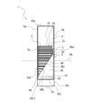
- FIG. 10 is a side view of the second modification of the centrifugal fan of Embodiment 1 as seen from the outlet side;
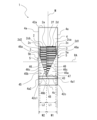
- FIG. 3 is a schematic diagram of a centrifugal fan according to a comparative example viewed in the axial direction of the rotating shaft;
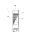
- FIG. 7 is a side view of the centrifugal fan of FIG. 6 as seen from the outlet side;
- FIG. 3 is a schematic view of the centrifugal fan according to Embodiment 2, viewed in the axial direction of the rotating shaft at the position of line AA of the centrifugal fan in FIG. 2;
- FIG. 11 is a side view of the centrifugal fan according to Embodiment 3 as viewed from the outlet side;
- FIG. 11 is a conceptual diagram of a usage example of the centrifugal fan according to Embodiment 3;
- FIG. 11 is a side view of a centrifugal fan according to Embodiment 4 as viewed from the outlet side;
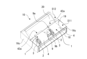
- FIG. 11 is a perspective view of an air conditioner according to Embodiment 5;
- FIG. 11 is a schematic diagram showing an internal configuration of an air conditioner according to Embodiment 5;
- FIG. 1 is a perspective view of a centrifugal fan 1 according to Embodiment 1.
- FIG. 2 is a side view of the centrifugal fan 1 of FIG. 1 as seen from the discharge port 42a side.
- FIG. 3 is a schematic diagram of the centrifugal fan 1 according to Embodiment 1 viewed in the axial direction of the rotation axis RA at the line AA position of the centrifugal fan 1 in FIG.
- FIG. 3 is also a conceptual diagram in which the scroll casing 4 of the centrifugal fan 1 of Embodiment 1 is projected in the axial direction of the rotation axis RA.
- a circumferential direction CD indicated by an arrow in FIGS. 1 and 3 indicates the circumferential direction of the fan 2 .
- FIG. 1 The basic structure of the centrifugal fan 1 will be described with reference to FIGS. 1 to 3.
- FIG. 1 The basic structure of the centrifugal fan 1 will be described with reference to FIGS. 1 to 3.
- FIG. 1
- the centrifugal fan 1 is a multi-blade centrifugal fan and has a fan 2 that generates an airflow and a scroll casing 4 that houses the fan 2 inside.
- the centrifugal fan 1 is a double suction type centrifugal fan in which air is sucked from both sides of the scroll casing 4 in the axial direction of the virtual rotation axis RA of the fan 2 .
- Fan 2 is a centrifugal fan.
- the fan 2 is connected to a motor (not shown) having a drive shaft.
- the fan 2 is rotationally driven by a motor, and the centrifugal force generated by the rotation forces the air radially outward.
- the fan 2 rotates in a rotation direction R indicated by an arrow by means of a motor or the like.
- the fan 2 includes a disk-shaped main plate 2a, an annular side plate 2c, and a plurality of blades 2d radially arranged around the rotation axis RA on the peripheral edge portion 2a1 of the main plate 2a.
- the fan 2 has a cylindrical shape with a plurality of blades 2d arranged on the main plate 2a.
- a fan suction port 2e of the fan 2 is formed in a portion of the fan 2 on the side of the side plate 2c opposite to the main plate 2a in the axial direction of the rotation axis RA.
- the fan suction port 2e allows gas to flow into a space surrounded by the main plate 2a and the plurality of blades 2d.
- the main plate 2a may have a plate shape, and may have a shape other than a disc shape, such as a polygonal shape.
- the thickness of the main plate 2a may be formed so that the thickness of the wall increases toward the center in the radial direction around the rotation axis RA, and the thickness is constant in the radial direction around the rotation axis RA. It may be formed at Further, the main plate 2a is not limited to being composed of a single plate-like member, and may be composed of a plurality of plate-like members fixed integrally. Note that the radial direction about the rotation axis RA is a direction perpendicular to the axial direction of the rotation axis RA.
- a boss portion 2b to which the drive shaft of the motor is connected is provided at the center of the main plate 2a.
- a shaft hole into which the drive shaft of the motor is inserted is formed in the boss portion 2b.
- the boss portion 2b is formed in a cylindrical shape, but the shape of the boss portion 2b is not limited to a cylindrical shape.
- the boss portion 2b may be formed in a columnar shape, for example, may be formed in a polygonal columnar shape.
- the main plate 2a is rotationally driven by a motor via the boss portion 2b.
- the fan 2 has an annular side plate 2c attached to the ends of the plurality of blades 2d opposite to the main plate 2a in the axial direction of the rotation axis RA.
- the side plate 2c fixes the ends of the plurality of blades 2d on the side opposite to the main plate 2a.
- the side plate 2c is provided on the outer peripheral surface 2f of the fan 2 and arranged to face the main plate 2a in the fan 2 .
- the side plate 2c is provided outside the blade 2d in the radial direction about the rotation axis RA.
- the side plate 2c may be provided at the tip of a plurality of blades 2d that protrude from the main plate 2a in the direction of the rotation axis RA.
- the side plate 2c is arranged to face the main plate 2a on the side opposite to the side on which the first side plate 2ca is arranged with respect to the annular first side plate 2ca arranged to face the main plate 2a. and an annular second side plate 2cb.
- the side plate 2c is a general term for the first side plate 2ca and the second side plate 2cb, and the fan 2 has the first side plate 2ca on one side with respect to the main plate 2a in the axial direction of the rotation axis RA, and the side plate 2c on the other side. It has a second side plate 2cb on its side.
- the first side plate 2ca is positioned on the right side and the second side plate 2cb is positioned on the left side of the main plate 2a, but the positions of the first side plate 2ca and the second side plate 2cb may be reversed.
- the plurality of blades 2d have one end connected to the main plate 2a and the other end connected to the side plate 2c, and are arranged in the circumferential direction CD around the rotation axis RA.
- Each of the blades 2d is arranged at least between the main plate 2a and the side plate 2c.
- the plurality of blades 2d are arranged in a circle around the boss portion 2b, and their base ends are fixed on the surface of the main plate 2a.
- a plurality of blades 2d are provided on one surface and the other surface of the main plate 2a in the axial direction of the rotation axis RA.
- the plurality of blades 2d are provided on both sides of the main plate 2a in the axial direction of the rotation axis RA.
- the blades 2d are arranged in the circumferential direction CD at a constant interval from each other on the peripheral edge portion 2a1 of the main plate 2a.
- Each blade 2d is provided so as to stand up from the main plate 2a and is formed in a plate shape.
- Each blade 2d is provided so as to stand substantially perpendicular to the main plate 2a, but is not limited to this, and each blade 2d may be provided inclined with respect to the vertical direction of the main plate 2a. .
- the fan 2 is driven to rotate around the rotation axis RA by being driven by a motor (not shown). As the fan 2 rotates, the gas outside the centrifugal blower 1 passes through the suction port 5 formed in the scroll casing 4 shown in FIG. It is sucked into the space surrounded by the blades 2d. As the fan 2 rotates, the air sucked into the space surrounded by the main plate 2a and the plurality of blades 2d passes through the space between the blades 2d and the adjacent blades 2d, and flows in the radial direction of the fan 2. sent to the outside.
- the scroll casing 4 accommodates the fan 2 inside and rectifies the air blown out from the fan 2 .
- the scroll casing 4 is a double suction type casing having side walls 4a formed with suction ports 5 (described later) on both sides of the main plate 2a in the axial direction of the rotation axis RA.
- the scroll casing 4 has a scroll portion 41 and a discharge portion 42 .
- the scroll casing 4 includes a peripheral wall 4c formed in a spiral shape, at least one side wall 4a having a bell mouth 3 forming a suction port 5 communicating with a space formed by the main plate 2a and the plurality of blades 2d, have
- the scroll portion 41 forms an air passage that converts the dynamic pressure of the airflow generated by the fan 2 into static pressure.
- the scroll portion 41 has a side wall 4a that covers the fan 2 from the axial direction of the rotation axis RA, and a peripheral wall 4c that surrounds the fan 2 from the radial direction of the rotation axis RA of the boss portion 2b.
- the scroll portion 41 has a tongue portion 43 that is positioned between the discharge portion 42 and forms a curved surface, and guides the airflow generated by the fan 2 to the discharge port 42a through the scroll portion 41.
- the internal space of the scroll portion 41 defined by the peripheral wall 4c and the side wall 4a is a space in which the air blown out from the fan 2 flows along the peripheral wall 4c.
- the scroll casing 4 has at least one side wall 4a with a bell mouth 3 forming an inlet 5.
- at least one side wall 4a of the scroll casing 4 includes two side walls 4a.
- the side walls 4a of Embodiment 1 are arranged on both sides of the fan 2 in the axial direction of the rotation axis RA.
- Two side walls 4a arranged on both sides of the fan 2 are formed so as to face each other via a peripheral wall 4c.
- the scroll casing 4 of Embodiment 1 includes a first side wall 4a1 and a second side wall 4a2 as side walls 4a.
- the first side wall 4a1 is the side wall 4a located on the side where the first side plate 2ca is arranged with respect to the main plate 2a.
- the second side wall 4a2 is the side wall 4a located on the side where the second side plate 2cb is arranged with respect to the main plate 2a.
- the side wall 4a is a general term for the first side wall 4a1 and the second side wall 4a2.
- a side wall 4 a of the scroll casing 4 is formed with a suction port 5 so that air can flow between the fan 2 and the outside of the scroll casing 4 .
- the suction port 5 communicates with the fan suction port 2e, and is an air intake port for introducing gas into a space surrounded by the main plate 2a and the plurality of blades 2d.
- a first suction port 5a is formed in the first side wall 4a1.
- the first suction port 5a is formed at a position facing the plate surface of the main plate 2a on the side where the first side plate 2ca is arranged.
- a second suction port 5b is formed in the second side wall 4a2.
- the second suction port 5b is formed at a position facing the plate surface of the main plate 2a on the side where the second side plate 2cb is arranged.
- the suction port 5 described above is a general term for the first suction port 5a and the second suction port 5b.
- a suction port 5 provided in the side wall 4a is formed by a bell mouth 3.
- the bellmouth 3 forms a suction port 5 that communicates a space outside the scroll casing 4 with a space formed by the main plate 2a and the plurality of blades 2d.
- the bell mouth 3 rectifies the gas sucked into the fan 2 and causes it to flow into the fan suction port 2 e of the fan 2 .
- the bell mouth 3 is formed so that the opening diameter gradually decreases from the outside to the inside of the scroll casing 4 . Due to this configuration of the side wall 4 a , the air in the vicinity of the suction port 5 smoothly flows along the bell mouth 3 and efficiently flows into the fan 2 from the suction port 5 .
- the peripheral wall 4c is a wall that guides the airflow generated by the fan 2 along the curved wall surface to the discharge port 42a.
- the peripheral wall 4c is spirally formed.
- the peripheral wall 4 c is formed such that the distance from the rotation axis RA gradually increases in the rotation direction R of the fan 2 .
- the gap between the peripheral wall 4c and the outer periphery of the fan 2 expands at a predetermined rate from the tongue portion 43 to the discharge portion 42 in the rotational direction R of the fan 2, and the air flow path area gradually increases. designed to grow.
- the spiral shape of the peripheral wall 4c includes, for example, a logarithmic spiral, an Archimedean spiral, or a shape based on an involute curve.
- the inner peripheral surface of the peripheral wall 4c forms a curved surface that smoothly curves along the circumferential direction of the fan 2 from a tongue portion 43 at the start of the spiral shape to a winding end portion 41b at the end of the spiral shape.
- the peripheral wall 4c is a wall provided between the side walls 4a facing each other, and forms a curved surface along the rotation direction R of the fan 2.
- the peripheral wall 4c is arranged parallel to the axial direction of the rotation axis RA and covers the fan 2. As shown in FIG.
- the peripheral wall 4c may be inclined with respect to the axial direction of the rotation axis RA of the fan 2, and is not limited to the configuration arranged parallel to the axial direction of the rotation axis RA.
- the peripheral wall 4c constitutes an inner wall surface facing the outer peripheral surface 2f of the fan 2.
- the peripheral wall 4 c faces the outer peripheral side end portions of the plurality of blades 2 d forming the outer peripheral surface 2 f of the fan 2 .
- the peripheral wall 4 c faces the air blowing side of the blades 2 d of the fan 2 .
- the peripheral wall 4c extends from a spiral-shaped winding start portion 43 to a winding end portion 41b located at the boundary between the discharge portion 42 and the scroll portion 41 on the side away from the tongue portion 43. , along the rotation direction R of the fan 2 .
- the tongue portion 43 is an upstream end portion of the peripheral wall 4c that forms a curved surface in the flow direction of the gas that flows along the peripheral wall 4c in the internal space of the scroll casing 4 as the fan 2 rotates.
- the winding end portion 41b is a downstream end portion of the peripheral wall 4c forming a curved surface in the flow direction of gas flowing along the peripheral wall 4c in the internal space of the scroll casing 4 as the fan 2 rotates.
- the scroll casing 4 has a curved surface at the winding start portion of the peripheral wall 4c near the rotation axis RA of the fan 2, and has a tongue portion 43 that guides the airflow generated by the fan 2 to the discharge port 42a.
- the peripheral wall 4c includes a tongue portion 43 at the end on the discharge portion 42 side.
- the tongue portion 43 is formed at the winding start portion of the spiral-shaped peripheral wall 4c.
- the tongue portion 43 is provided at the boundary between the later-described discharge portion 42 and the diffuser plate 42c.
- the tongue portion 43 is formed to have a curved surface, and is formed in an arc shape when viewed from the axial direction of the rotation axis RA.
- the tongue portion 43 is formed with a predetermined radius of curvature, and the peripheral wall 4c is smoothly connected to the diffuser plate 42c via the tongue portion 43 .
- the tongue portion 43 has substantially the same shape in the axial direction of the rotation axis RA when viewed from the discharge port 42a, and has a shape along the axial direction of the rotation axis RA.
- the tongue portion 43 suppresses the inflow of air from the winding end to the winding start of the spiral flow path.
- the tongue portion 43 is provided in the upstream portion of the ventilation passage, and serves to divide the air flow in the rotation direction R of the fan 2 and the air flow in the discharge direction from the downstream portion of the ventilation passage toward the discharge port 42a. have Further, the static pressure of the air flowing into the discharge portion 42 increases while passing through the scroll casing 4 and becomes high pressure. Therefore, the tongue portion 43 has a function of partitioning such a pressure difference.
- extension plate 45 The scroll casing 4 protrudes from the tongue portion 43, as shown in FIGS. It has a plate-shaped extension plate 45 that extends.
- the extension plate 45 is formed to protrude from the tongue portion 43 in the reverse rotation direction of the fan 2 .
- the reverse rotation direction of the fan 2 is the direction opposite to the rotation direction R of the fan 2 .
- the extension plate 45 extends from the tongue portion 43 along the outer peripheral edge 2g of the fan 2 in the circumferential direction CD and extends in the axial direction of the rotation axis RA.
- the extension plate 45 is formed such that the side plate 2c side portion is longer than the main plate 2a side portion in the circumferential direction CD of the fan 2 (see FIG. 1).
- the length of the extension plate 45 protruding from the tongue portion 43 is the longest on the side plate 2c side and the shortest on the main plate 2a side. That is, the extension plate 45 is formed such that the portion closer to the side plate 2c is longer in the circumferential direction CD than the portion closer to the main plate 2a in the axial direction of the rotation axis RA.
- a portion on the side plate 2c side and a portion on the side of the main plate 2a indicate the relative positional relationship between the position of the extension plate 45 and the other position in the axial direction of the rotation axis RA.
- the scroll casing 4 when the scroll casing 4 is projected in the axial direction of the rotation axis RA, the scroll casing 4 has a discharge port edge portion 42a1, which is a portion forming the discharge port 42a, near the tongue portion 43. has a tongue portion side end portion 42c1 that is the end portion of the Further, as shown in FIG. 3, the scroll casing 4 has a tongue portion side end at a discharge port edge portion 42a1, which is a portion forming the discharge port 42a when the scroll casing 4 is projected in the axial direction of the rotation axis RA. It has a distal end 42c2 at the end opposite to the portion 42c1.
- the tongue-side end 42c1 is the first end, and the distal end 42c2 is the second end.
- the tongue portion side end portion 42c1 is located on the opposite side of the distal end portion 46a in the circumferential direction CD with respect to the reference line RL which is perpendicular to the outlet edge portion 42a1 from the rotation axis RA. are doing.
- the distal end portion 46a is the distal end portion 46 of the extension plate 45 in the projecting direction from the tongue portion 43 and is located at the boundary portion with the side wall 4a.
- the extension plate 45 is formed such that when the inside of the scroll casing 4 is viewed from the discharge port 42a, the tip portion 46a is located between the tongue portion 43 and the vertex portion 2h. .
- the extension plate 45 includes a base portion 47 that serves as a boundary portion with the tongue portion 43 .
- the extension plate 45 is formed to have a constant thickness within a predetermined thickness range from the base portion 47, which is the boundary portion with the tongue portion 43, to the distal end portion 46a. .
- the extension plate 45 is formed to have the same thickness as the thickness of the plate forming the peripheral wall 4c.
- the thickness of the extension plate 45 is, for example, 2 mm or less when the material of the extension plate 45 is steel plate, and is 4 mm or less when the material of the extension plate 45 is resin. It is not limited to these thicknesses.
- the extension plate 45 of Embodiment 1 includes a first plate portion 45a and a second plate portion 45b formed in the shape of a right triangle when viewed from the discharge port 42a.
- the extension plate 45 is formed so that the oblique side of the first plate portion 45a and the oblique side of the second plate portion 45b face each other in the axial direction of the rotation axis RA.
- the extension plate 45 has a V-shaped notch 46b when viewed from the discharge port 42a. Air that is pressurized in the scroll casing 4 and directed to the discharge port 42a passes through the notch 46b and is discharged to the outside from the discharge port 42a. A tip portion 46 of the extension plate 45 forms an edge portion 46c of the extension plate 45, and the edge portion 46c of the extension plate 45 forms a V-shaped notch portion 46b. An edge portion 46c of the extension plate 45 is formed in a V shape.
- the extension plate 45 has an edge portion constituted by a tip portion 46 formed linearly between a portion on the side plate 2c side and a portion on the main plate 2a side like an edge portion 46c shown in FIG.
- the extension plate 45 has a shortest portion 48 which is the shortest portion of the extension plate 45 in the projection direction of the extension plate 45 projecting from the tongue portion 43 when viewed from the discharge port 42a. , at the position of the main plate 2a in the axial direction of the rotation axis RA.
- the centrifugal blower 1 has the extension plate 45 so that the position of the main plate 2a in the axial direction of the rotation axis RA is positioned relative to the rotation axis RA when the interior is viewed from the discharge port 42a. is the largest part of the vertical opening width.
- the discharge portion 42 forms a discharge port 42a through which the airflow generated by the fan 2 and passed through the scroll portion 41 is discharged.
- the discharge part 42 is composed of a hollow tube having a rectangular cross section perpendicular to the direction in which air flows along the peripheral wall 4c.
- the cross-sectional shape of the discharge part 42 is not limited to a rectangle.
- the discharge portion 42 forms a flow path that guides the air that is sent out from the fan 2 and flows through the gap between the peripheral wall 4 c and the fan 2 so as to be discharged to the outside of the scroll casing 4 .
- One end of the discharge portion 42 is fixed to the scroll casing 4 as shown in FIG.
- the other end of the discharge portion 42 forms a discharge port 42a through which the air that has flowed through the flow path inside the discharge portion 42 is discharged to the outside air.
- the discharge part 42 has an extension plate 42b, a diffuser plate 42c, a first side plate portion 42d, and a second side plate portion 42e.
- the extension plate 42b is formed integrally with the peripheral wall 4c so as to smoothly continue to the winding end portion 41b on the downstream side of the peripheral wall 4c.
- the diffuser plate 42c is formed integrally with the tongue portion 43 of the scroll casing 4 and faces the extension plate 42b.
- the diffuser plate 42c is formed at a predetermined angle with respect to the extension plate 42b, for example, so that the cross-sectional area of the flow path gradually expands along the direction of air flow in the discharge portion 42. It is not limited to this configuration.
- the first side plate portion 42d is formed integrally with the first side wall 4a1 of the scroll casing 4, and the second side plate portion 42e is formed integrally with the second side wall 4a2 on the opposite side of the scroll casing 4.
- the first side plate portion 42d and the second side plate portion 42e are formed between the extension plate 42b and the diffuser plate 42c.
- the discharge portion 42 has a channel with a rectangular cross section formed by the extension plate 42b, the diffuser plate 42c, the first side plate portion 42d, and the second side plate portion 42e.
- the flow of air flowing inside the scroll casing 4 will be described.
- the air sent out from the fan 2 flows in the direction of the arrow F1 shown in FIG.
- the tongue portion 43 serves as a branching point of the flow path.
- An air flow path (arrow F2) toward the discharge port 42a and a flow path (arrow F3) for air flow reintroducing from the tongue 43 to the upstream side are formed at the inlet 42g of the discharge portion 42.
- the tongue portion 43 has the function of partitioning the pressure difference, and has the function of guiding the air flowing into the discharge portion 42 to each flow channel by its curved surface.
- FIG. 4 is a side view of the first modification of the centrifugal fan 1 of Embodiment 1, viewed from the discharge port 42a side.
- the extension plate 45 has a U-shaped notch portion 46b1 when viewed from the discharge port 42a. Air that is pressurized in the scroll casing 4 and directed to the discharge port 42a passes through the notch 46b1 and is discharged to the outside from the discharge port 42a.
- a tip portion 46 of the extension plate 45 forms an edge portion 46c of the extension plate 45, and the edge portion 46c of the extension plate 45 forms a U-shaped notch portion 46b1.
- An edge portion 46c of the extension plate 45 is formed in a U shape.
- FIG. 5 is a side view of the second modification of the centrifugal fan 1 of Embodiment 1, viewed from the discharge port 42a side.
- the extension plate 45 has a notch portion 46b2 that is cut out in a substantially V shape as a whole when viewed from the discharge port 42a. Air that is pressurized in the scroll casing 4 and directed to the discharge port 42a passes through the notch 46b2 and is discharged to the outside from the discharge port 42a.
- a tip portion 46 of the extension plate 45 forms an edge portion 46c of the extension plate 45, and the edge portion 46c of the extension plate 45 forms a V-shaped notch portion 46b2.
- An edge portion 46c of the extension plate 45 is formed in a substantially V shape as a whole. Further, the edge portion 46c forms an edge portion formed in a wavy line shape instead of a linear shape when viewed from the ejection port 42a side.
- the extension plate 45 has a wavy edge portion forming the notch portion 46b2 between the portion on the side plate 2c side and the portion on the main plate 2a side like the edge portion 46c shown in FIG.
- centrifugal fan 1 The operation of the centrifugal fan 1 will be described with reference to FIG.
- a motor (not shown)
- the main plate 2a connected to the motor shaft rotates, and the plurality of blades 2d rotate around the rotation axis RA via the main plate 2a.
- the fan 2 rotates, air outside the scroll casing 4 is drawn into the scroll casing 4 through the suction port 5 .
- the air sucked inside the scroll casing 4 is guided by the bell mouth 3 and sucked into the fan 2 .
- the air sucked into the fan 2 is blown out radially outward of the fan 2 as an airflow to which dynamic pressure and static pressure are added in the process of passing between the plurality of blades 2d.
- the airflow blown out from the fan 2 is blown out from the fan 2 into the inside of the scroll casing 4 by the boosting effect of the fan 2 .
- the airflow flowing through the scroll casing 4 is pressurized by flowing through the air passage that gradually expands from the winding start side to the winding end side due to the spiral-shaped peripheral wall 4c.
- the air blown out from the fan 2 into the scroll casing 4 is decelerated in the expanded air passage formed by the peripheral wall 4c of the scroll casing 4, recovers the static pressure, and is blown out from the discharge port 42a shown in FIG. be.
- the centrifugal fan 1 has a plate-shaped extension plate 45 that protrudes from the tongue portion 43 and extends from the tongue portion 43 along the outer peripheral edge 2g of the fan 2 while being spaced apart from the fan 2,
- the extension plate 45 is formed such that the portion on the side plate 2c side is longer than the portion on the main plate 2a side in the circumferential direction CD of the fan 2 .
- the extension plate 45 provided on the side plate 2c side suppresses the backflow of the airflow from the side of the side plate 2c toward the inside of the scroll casing 4, so that the airflow on the side plate 2c side is smoothly discharged. 42a.
- the centrifugal fan 1 changes the length of the extension plate 45 between the portion on the side of the main plate 2a and the portion on the side of the side plate 2c. , the backflow of the airflow generated in the portion on the side plate 2c side can be reduced, and the decrease in the air volume can be suppressed. Since the centrifugal fan 1 has the extension plate 45 , the airflow can be discharged from the discharge port 42 a along the wind speed distribution of the airflow flowing inside the scroll casing 4 .
- the extension plate 45 is formed in a plate shape, the distance between the extension plate 45 and the discharge port 42a can be secured, and a sufficient air passage can be secured. can be secured.
- the tongue portion side end portion 42c1 is located at the boundary portion with at least one side wall 4a at the tip portion 46 of the extension plate 45 in the projecting direction from the tongue portion 43 with respect to the reference line RL. It is located on the opposite side in the circumferential direction CD from the located distal end portion 46a. Therefore, the centrifugal fan 1 can secure the opening area of the discharge port 42a, and can suppress the reduction of the discharged air volume.
- FIG. 6 is a schematic diagram of the centrifugal blower 111 according to the comparative example viewed in the axial direction of the rotation axis RA. Note that FIG. 6 is also a conceptual diagram in which the scroll casing 114 of the centrifugal fan 111 of the comparative example is projected in the axial direction of the rotation axis RA.
- FIG. 7 is a side view of the centrifugal blower 111 of FIG. 6 viewed from the outlet 142a side.
- a centrifugal fan 111 of a comparative example shown in FIGS. 6 and 7 is obtained by adding reference numerals to the centrifugal fan of Patent Document 1 for explanation.
- the centrifugal blower 111 installed in a narrow space cannot secure a sufficient distance between the rotation axis RA and the discharge port 142a. Therefore, the centrifugal fan 111 cannot increase the length of the discharge portion 142 .
- a centrifugal fan 111 according to the comparative example has a fan 112 and a scroll casing 114 .
- Scroll casing 114 has peripheral wall 114 c and tongue 143 .
- the discharge port edge portion 142a1 which forms the discharge port 142a, has a tongue-side end portion 142c1. and a distal end 142c2.
- the tongue portion 143 of the centrifugal blower 111 is formed so that the wall thickness of the tongue portion 143 is larger than the thickness of the peripheral wall 114c when viewed in the axial direction of the rotation axis RA.
- the thickness of the wall of the tongue portion 143 increases, the distance between the tongue portion side end portion 142c1 and the distal end portion 142c2 becomes smaller, and the opening area of the discharge port 142a becomes smaller.
- the thickness of the wall of the tongue portion 143 is increased, as shown in FIG.
- the centrifugal fan 111 of the comparative example As shown in FIG. 6, the rotation axis RA or the centrifugal fan 1 does not have a reference line RL extending vertically from the rotation axis RA to the outlet edge 42a1. Compared to the centrifugal fan 1 of form 1, the distance between the tongue side end 142c1 and the far end 142c2 is small. Therefore, the centrifugal fan 111 according to the comparative example has a smaller opening area of the discharge port 142a than the centrifugal fan 1 of the first embodiment.
- the centrifugal blower 111 cannot expand the air passage sufficiently, so that the effect of increasing the pressure in the scroll casing 4 cannot be exhibited. Since the opening of 142a is narrow, there is a risk that the amount of discharged air will decrease.
- the centrifugal fan 1 of Embodiment 1 has the extension plate 45 configured as described above and the tongue portion side end portion 42c1. Therefore, in the centrifugal fan 1, the extension plate 45 suppresses the backflow of the airflow from the side of the discharge port 42a into the scroll casing 4, and the extension plate 45 is formed in a plate shape to ensure the pressure in the scroll casing 4. can.
- the centrifugal fan 1 secures the opening area of the discharge port 42a by locating the tongue portion side end portion 42c1 on the opposite side of the front end portion 46a with respect to the reference line RL in the circumferential direction CD. It is possible to suppress a decrease in the amount of discharged air.
- Centrifugal fan 1 of Embodiment 1 is installed in a narrow space, and even if a sufficient distance cannot be secured between rotating shaft RA and discharge port 142a, extension plate 45 and tongue-side end 42c1 can be arranged. It is possible to exhibit the above effect by having it.
- the extension plate 45 is formed to have a constant thickness within a predetermined thickness range from the base portion 47, which is the boundary portion with the tongue portion 43, to the distal end portion 46a. ing. Therefore, the centrifugal fan 1 can secure the distance between the extension plate 45 and the discharge port 42a, and can secure a sufficient air passage, so that the pressure inside the scroll casing 4 can be secured. In addition, since the shape of the extension plate 45 of the centrifugal fan 1 is not complicated, the scroll casing 4 can be easily manufactured, and the manufacturing cost can be suppressed.
- the extension plate 45 is formed so that the thickness of the plate forming the extension plate 45 is the same as the thickness of the plate forming the peripheral wall 4c. Therefore, the centrifugal fan 1 does not narrow the air passage leading to the outlet 142a like the tongue 143 of the centrifugal fan 1 of the comparative example. Since the passage can be secured, the pressure in the scroll casing 4 can be secured. Further, in the centrifugal fan 1, the extension plate 45 and the peripheral wall 4c are formed to have the same thickness, and the shape of the scroll casing 4 is not complicated. Manufacturing costs can be suppressed.
- the extension plate 45 includes a first plate portion 45a and a second plate portion 45b which are formed in the shape of a right triangle when viewed from the discharge port 42a. It is formed so that the oblique side of 45b faces each other.
- the centrifugal blower when the extension plate 45 is not provided, the backflow area of the airflow increases in the scroll casing 4 from the main plate 2a side to the side plate 2c side. Further, the centrifugal blower is generally formed so that the flow rate of airflow from the inside of the scroll casing toward the discharge port is large at the portion where the main plate 2a is formed.
- the centrifugal fan 1 has the first plate portion 45a and the second plate portion 45b, thereby securing an opening area in the portion of the main plate 2a where the flow rate of airflow from the inside of the scroll casing 4 toward the discharge port 42a is large. , is formed so that the discharge amount of the airflow does not decrease. Further, since the centrifugal blower 1 has the first plate portion 45a and the second plate portion 45b, the opening portion on the side of the side plate 2c where the backflow of the air flow increases when the extension plate 45 is not provided is the extension plate. 45 and can suppress backflow of airflow.
- the centrifugal fan 1 by changing the length of the extension plate 45 between the portion on the side of the main plate 2a and the portion on the side of the side plate 2c, the air flow is not reduced in the portion on the side of the main plate 2a where the air volume concentrates, and the side plate is It is possible to reduce the backflow of the airflow generated in the portion on the 2c side, and suppress the decrease in the air volume.
- the extension plate 45 has a V-shaped notch portion 46b when viewed from the discharge port 42a.
- the centrifugal fan 1 has the notch 46b to secure an opening area in the main plate 2a portion, and is formed so as not to decrease the discharge amount of the airflow. In the centrifugal fan 1, the opening on the side plate 2c side is covered with the extension plate 45, which can suppress backflow of airflow.
- the centrifugal fan 1 by changing the length of the extension plate 45 between the portion on the side of the main plate 2a and the portion on the side of the side plate 2c, the air flow is not reduced in the portion on the side of the main plate 2a where the air volume concentrates, and the side plate is It is possible to reduce the backflow of the airflow generated in the portion on the 2c side, and suppress the decrease in the air volume.
- the extension plate 45 has a U-shaped notch portion 46b when viewed from the discharge port 42a.
- the centrifugal fan 1 has the notch 46b to secure an opening area in the main plate 2a portion, and is formed so as not to decrease the discharge amount of the airflow.
- the opening on the side plate 2c side is covered with the extension plate 45, which can suppress backflow of airflow.
- the centrifugal fan 1 by changing the length of the extension plate 45 between the portion on the side of the main plate 2a and the portion on the side of the side plate 2c, the air flow is not reduced in the portion on the side of the main plate 2a where the air volume concentrates, and the side plate is It is possible to reduce the backflow of the airflow generated in the portion on the 2c side, and suppress the decrease in the air volume.
- the extension plate 45 has a wavy line-like edge portion forming the notch portion 46b from the portion on the main plate 2a side to the portion on the side plate 2c side.
- the end of the extension plate 45 is formed in a wavy line, so that the phase of the pressure fluctuation that occurs when the blade 2d passes near the end of the extension plate 45 can be shifted. resulting noise can be reduced.
- FIG. 8 is a schematic diagram of the centrifugal fan 1 according to Embodiment 2, viewed in the axial direction of the rotation axis RA at the line AA position of the centrifugal fan 1 in FIG.
- FIG. 8 is also a conceptual diagram in which the scroll casing 4 of the centrifugal fan 1 of Embodiment 2 is projected in the axial direction of the rotation axis RA. 1 to 5 are denoted by the same reference numerals, and description thereof will be omitted.
- the centrifugal fan 1 according to Embodiment 2 further specifies the configuration of the plurality of blades 2d.
- the configuration of portions other than the plurality of blades 2d is the same as that of the centrifugal fan 1 according to the first embodiment. Therefore, in the following description, the configuration of the plurality of blades 2d of the centrifugal fan 1 according to the second embodiment will be mainly described with reference to FIG.
- Each of the plurality of blades 2d has a turbo blade portion 12 that includes an inner peripheral end 14 positioned on the side of the rotation axis RA in a radial direction about the rotation axis RA and that constitutes a rearward blade.
- each of the plurality of blades 2d includes an outer peripheral end 15 located on the outer peripheral side of the inner peripheral end 14 in the radial direction about the rotation axis RA, and has a sirocco blade portion 13 that constitutes a forward blade. .
- the sirocco blade portion 13 constitutes the outer peripheral side of the blade 2d
- the turbo blade portion 12 constitutes the inner peripheral side of the blade 2d. That is, in the radial direction of the fan 2, the blades 2d are configured in order of the turbo blade portion 12 and the sirocco blade portion 13 from the rotation axis RA toward the outer peripheral side.
- the turbo blade portion 12 and the sirocco blade portion 13 are integrally formed.
- the turbo blade 12 forms the leading edge of the blade 2d
- the sirocco blade 13 forms the trailing edge of the blade 2d.
- the forming area of the turbo blade portion 12 is formed larger than the forming area of the sirocco blade portion 13 in the radial direction of the fan 2 .
- the interval between two blades 2d adjacent to each other in the circumferential direction CD among the plurality of blades 2d is defined as the interval between blades, as shown in FIG. It widens toward the edge.
- the gap between the blades of the turbo blade portion 12 widens from the inner peripheral side to the outer peripheral side.
- the space between the blades of the sirocco blade portion 13 is wider than the space between the blades of the turbo blade portion 12 and spreads from the inner peripheral side to the outer peripheral side.
- Each of the plurality of blades 2d has a turbo blade portion 12 including an inner peripheral end 14 and forming a rearward blade, and a sirocco blade portion 13 comprising an outer peripheral end 15 and forming a forward blade.
- the centrifugal fan 1 has a turbo blade portion 12 on the inner peripheral side of the fan 2 and a sirocco blade portion 13 on the outer peripheral side of the fan 2, so that pressure can be increased between the blades.
- the centrifugal fan 1 has a turbo blade portion 12 on the inner peripheral side of the fan 2 and a sirocco blade portion 13 on the outer peripheral side of the fan 2, so that pressure can be increased between the blades. , the airflow tends to flow back into the scroll casing 4 from the discharge port 42a side.
- the centrifugal blower 1 has the extension plate 45 having the above-described structure, so that the extension plate 45 provided on the side plate 2c side suppresses the backflow of the airflow from the discharge port 42a side toward the inside of the scroll casing 4. The airflow in the portion on the 2c side can be smoothly guided to the discharge port 42a.
- the centrifugal fan 1 is compared with the case where the fan 2 does not have the turbo blade portion 12 and the sirocco blade portion 13. As a result, the effect of preventing the backflow of the airflow by the extension plate 45 can be exhibited more remarkably.
- FIG. 9 is a side view of the centrifugal fan 1 according to Embodiment 3 as viewed from the outlet 42a side.
- FIG. 10 is a conceptual diagram of a usage example of the centrifugal fan 1 according to the third embodiment. Parts having the same configuration as the centrifugal blower 1 shown in FIGS. 1 to 8 are denoted by the same reference numerals, and descriptions thereof are omitted.
- the centrifugal fan 1 according to Embodiment 3 further specifies the configurations of the fan 2 and the extension plate 45 . Configurations of portions other than the fan 2 and the extension plate 45 are the same as those of the centrifugal fan 1 according to the first or second embodiment. Therefore, in the following description, the configurations of the fan 2 and the extension plate 45 of the centrifugal fan 1 according to Embodiment 3 will be mainly described with reference to FIG.
- a plurality of blades 2d that constitute the fan 2 are provided on one surface and the other surface of the main plate 2a in the axial direction of the rotation axis RA.
- the first plurality of blades 2d1 provided on one surface of the main plate 2a and the second plurality of blades 2d2 provided on the other surface of the main plate 2a It is formed so that the length which protrudes from 2a differs.
- the main plate 2a that constitutes the fan 2 is formed deviated from the center position M of the fan 2 to one side in the axial direction of the rotation axis RA.
- the fan 2 is formed such that the length L1 of the first plurality of blades 2d1 is longer than the length L2 of the second plurality of blades 2d2.
- the main plate 2a of the fan 2 is arranged at a position shifted toward the second side plate 2cb with respect to the center position M so as to be closer to the second side plate 2cb than the first side plate 2ca.
- the extension plate 45 has a shortest portion 48 which is the shortest portion of the extension plate 45 in the projection direction of the extension plate 45 projecting from the tongue portion 43 when viewed from the discharge port 42a. , at the position of the main plate 2a in the axial direction of the rotation axis RA.
- the shortest portion 48 of the extension plate 45 is formed to be shifted to one side from the center position M of the fan 2 in the axial direction of the rotation axis RA.
- the extension plate 45 is formed such that the maximum width W1 of the first plate portion 45a is larger than the maximum width W2 of the second plate portion 45b in the axial direction of the rotation axis RA.
- the maximum width W1 of the first plate portion 45a is the width of the extension plate 45 between the first side wall 4a1 and the shortest portion 48 in the base portion 47
- the maximum width W2 of the second plate portion 45b is , the width of the extension plate 45 between the second side wall 4 a 2 and the shortest portion 48 at the base portion 47 .
- the first plate portion 45a covers the first plurality of blades 2d1 in the radial direction of the fan 2, and the second plate portion 45b covers the second plurality of blades 2d2 in the radial direction of the fan 2.
- the centrifugal blower 1 has the extension plate 45 so that the position of the main plate 2a in the axial direction of the rotation axis RA is positioned relative to the rotation axis RA when the interior is viewed from the discharge port 42a. It becomes the part where the vertical opening width is the widest.
- the widest portion of the opening width perpendicular to the rotation axis RA is formed deviated from the center position M of the fan 2 in the axial direction of the rotation axis RA.
- the wall surface portion 60 shown in FIG. 10 is the wall surface of the case 16 of the air conditioner 10, which will be described later, or the wall surface of various devices such as a blower device in which the centrifugal blower 1 is incorporated. Further, in FIG. 10 , the wall surface portion 60 and the motor 9 are resistors for the airflow flowing into the centrifugal fan 1 . In the apparatus of FIG. 10, the motor 9 is a resistor that blocks the flow of air and is arranged at a position facing the wall surface 60 with the centrifugal blower 1 therebetween. The motor 9 is connected to the main plate 2a via a motor shaft 9a.
- the main plate 2a is displaced from the center position M of the fan 2 in the axial direction of the rotation axis RA so that the distance between the scroll casing 4 and the resistor located opposite to the side wall 4a is smaller.
- the shortest part 48 is displaced from the center position M of the fan 2 in the axial direction of the rotation axis RA in the direction where the distance between the scroll casing 4 and the resistor located opposite to the side wall 4a is smaller.
- the centrifugal fan 1 is arranged such that the main plate 2a and the shortest portion 48 are shifted from the center position M of the fan 2 to the side where the distance WL1 and the distance WL2 are smaller.
- the centrifugal fan 1 is formed so that the positions of the main plate 2a and the shortest portion 48 are located on the second side wall 4a2 side with respect to the center position M of the fan 2.
- the centrifugal fan 1 has the main plate 2a and the shortest portion 48 It is formed so as to be located on the first side wall 4a1 side with respect to the center position M of the fan 2 .
- the centrifugal fan 1 In the centrifugal fan 1, the larger the distance between the scroll casing 4 and the resistor located opposite the side wall 4a, the greater the amount of air that flows in from the suction port 5.
- the centrifugal fan 1 by shifting the position of the main plate 2a to the side where the amount of suction air flowing from the suction port 5 is small by a resistor, the total area of the blades 2d on the side where the amount of suction air is large can be increased to increase the pressure. The amount of discharged air can be increased.
- the centrifugal fan 1 the larger the distance between the scroll casing 4 and the resistor located opposite the side wall 4a, the greater the amount of discharged air, and the airflow near the side plate 2c flows back into the scroll casing 4 from the discharge port 42a side.
- the effect of air currents on In the centrifugal fan 1, by shifting the position of the shortest part 48 to the side where the suction air volume is small, the width of the extension plate 45 on the side of the large suction air volume in the axial direction of the rotation axis RA can be increased. Backflow of air current can be suppressed.
- the extension plate 45 has a shortest portion 48, which is the shortest portion of the extension plate 45 in the projecting direction when viewed from the discharge port 42a, at the position of the main plate 2a in the axial direction of the rotation axis RA. . Further, the main plate 2a is formed so as to be shifted to one side from the center position M of the fan 2 in the axial direction of the rotation axis RA. In the centrifugal fan 1 of the first embodiment, the main plate 2a and the shortest part 48 are displaced from the center position M and arranged on the side with the smaller suction air volume even when the suction air volume is different on both sides of the double suction type centrifugal fan 1. And the same effects as those of the second embodiment and the like can be exhibited.
- the centrifugal fan 1 has a fan 2 in which the main plate 2a is displaced in the axial direction of the rotation axis RA so that the distance between the side wall 4a and the airflow resistor is smaller, so that the total area of the blades 2d on the side where the amount of air drawn is large.
- the centrifugal fan 1 has the fan 2 in which the shortest part 48 is shifted in the axial direction of the rotation axis RA in the direction where the distance between the side wall 4a and the airflow resistor is smaller.
- the centrifugal fan 1 can increase the width of the extension plate 45 on the side of the rotating shaft RA where the amount of suction air is large, and can suppress the backflow of the airflow in the vicinity of the side plate 2c.
- the extension plate 45 has the shortest portion 48 formed at the position of the main plate 2a in the axial direction of the rotation axis RA.
- the centrifugal fan 1 changes the length of the extension plate 45 between the portion on the side of the main plate 2a and the portion on the side of the side plate 2c. can reduce the backflow of the airflow generated in the portion on the side of the side plate 2c without reducing the air flow rate, thereby suppressing the decrease in the air volume.
- FIG. 11 is a side view of the centrifugal fan 1 according to Embodiment 4 as viewed from the outlet 42a side. 1 to 10 are denoted by the same reference numerals, and description thereof will be omitted.
- the double-suction centrifugal blower 1 has been described in the first to third embodiments, the centrifugal blower 1 is not limited to the double-suction centrifugal blower 1, and may be a single-suction centrifugal blower 1. It's okay.
- the centrifugal blower 1 only needs to have at least one side wall 4a in which the suction port 5 is formed.
- the scroll casing 4 of the centrifugal blower 1 covers the fan 2 from the axial direction of the rotation axis RA of the fan 2, and includes a side wall 4a formed with a suction port 5 for taking in air, and a peripheral wall surrounding the fan 2 from the radial direction of the rotation axis RA. 4c and Further, the scroll casing 4 of the single-suction centrifugal fan 1 has a side wall 4a3 perpendicular to the axial direction of the rotating shaft RA.
- the scroll casing 4 of Embodiment 4 is a single suction type casing in which an air suction port 5 is formed only on one side of the fan 2 in the axial direction of the rotation axis RA.
- the side wall 4a3 is not formed with the suction port 5, and the side wall 4a3 and the first side wall 4a1 are formed so as to face each other.
- the side wall 4a3 and the first side wall 4a1 are provided on both sides of the fan 2 in the axial direction of the rotation axis RA.
- the side wall 4a3 may be formed so as to face the second side wall 4a2 (see FIG. 2) instead of the first side wall 4a1.
- the side wall 4a is used as a general term for the first side wall 4a1 or the second side wall 4a2 and the side wall 4a3.
- a centrifugal fan 1 according to Embodiment 4 includes one side wall 4a having a suction port 5 formed therein, and includes one side wall 4a having no suction port 5 formed therein.
- a plurality of blades 2d of the centrifugal fan 1 are provided on one side of the main plate 2a in the axial direction of the rotation axis RA, as shown in FIG.
- the main plate 2a of the fan 2 is positioned closer to the side wall 4a3 than the side plate 2c, and the side plate 2c of the fan 2 is positioned closer to the first side wall 4a1 than the main plate 2a.
- the extension plate 45 of Embodiment 4 is formed in the shape of a right triangle when viewed from the discharge port 42a.
- the extension plate 45 has a cutout portion 46b which is cut obliquely when viewed from the discharge port 42a.
- a tip portion 46 of the extension plate 45 forms an edge portion 46c of the extension plate 45, and the edge portion 46c of the extension plate 45 forms an oblique notch portion 46b.
- the edge 46c of the extension plate 45 is obliquely formed.
- the extension plate 45 may have an edge portion formed by the tip portion 46 formed linearly between the portion on the side plate 2c side and the portion on the main plate 2a side like the edge portion 46c shown in FIG.
- the extension plate 45 may have a wavy edge portion formed by the tip portion 46 between the portion on the side plate 2c side and the portion on the main plate 2a side like the edge portion 46c shown in FIG.
- the extension plate 45 protruding from the tongue portion 43 has the longest length on the side plate 2c side and the shortest length on the main plate 2a side.
- the length of the extension plate 45 protruding from the tongue portion 43 is the longest on the side of the first side wall 4a1 where the suction port 5 is formed. The portion on the side of the side wall 4a3 that is not covered is the shortest.
- the extension plate 45 has a shortest portion 48 which is the shortest portion of the extension plate 45 in the projecting direction of the extension plate 45 projecting from the tongue portion 43 when viewed from the discharge port 42a. , at the position of the main plate 2a in the axial direction of the rotation axis RA.
- the centrifugal blower 1 has the extension plate 45 so that the position of the main plate 2a in the axial direction of the rotation axis RA is positioned relative to the rotation axis RA when the interior is viewed from the discharge port 42a. is the largest part of the vertical opening width.
- the scroll casing 4 of Embodiment 4 is a single suction type casing in which an air suction port 5 is formed only on one side of the fan 2 in the axial direction of the rotation axis RA.
- the centrifugal fan 1 of Embodiment 4 is a single-suction centrifugal fan 1 having one side wall 4a with a suction port 5 formed thereon and sucking air into the scroll casing 4 from one side. be.
- the tongue portion side end portion 42c1 and the extended plate 45 extending from the tongue portion 43 toward the portion on the side plate 2c side from the portion on the side of the main plate 2a toward the portion on the side plate 2c side are elongated. have.
- the extension plate 45 suppresses the backflow of the airflow from the discharge port 42a side to the inside of the scroll casing 4, and the extension plate 45 is formed in a plate shape to increase the pressure inside the scroll casing 4. can be ensured.
- the tongue portion side end portion 42c1 is located on the opposite side of the distal end portion 46a with respect to the reference line RL in the circumferential direction CD. The area can be secured, and a decrease in the amount of discharged air can be suppressed.
- the same effects as those of the centrifugal fan 1 of Embodiments 1 to 3 can be exhibited. can.
- Embodiment 5 is a perspective view of the air conditioner 10 according to Embodiment 5.
- FIG. FIG. 13 is a schematic diagram showing the internal configuration of the air conditioner 10 according to Embodiment 5. As shown in FIG. Regarding the centrifugal fan 1 used in the air conditioner 10 according to Embodiment 5, parts having the same configurations as those of the centrifugal fan 1 and the like shown in FIGS. omitted. Further, in FIG. 13, the upper surface portion 16a is omitted in order to show the internal configuration of the air conditioner 10. As shown in FIG.
- An air conditioner 10 according to Embodiment 5 includes a centrifugal fan 1 and a heat exchanger 20 through which air flowing by the centrifugal fan 1 passes.
- the number of centrifugal fans 1 used in the air conditioner 10 may not be singular, but may be plural.
- the air conditioner 10 according to Embodiment 5 includes a case 16 that accommodates the centrifugal fan 1 and the heat exchanger 20 therein.
- the case 16 as shown in FIG. 12, is formed in a rectangular parallelepiped shape including an upper surface portion 16a, a lower surface portion 16b, and a side surface portion 16c.
- the shape of the case 16 is not limited to a rectangular parallelepiped shape. It may be in shape.
- the case 16 has, as one of the side portions 16c, a side portion 16c in which the case outlet 17 is formed.
- the case 16 has a side portion 16c formed with a case suction port 18 on the side opposite to the side on which the case discharge port 17 is formed.
- a filter for removing dust in the air may be arranged at the case inlet 18 .
- the formation positions of the case discharge port 17 and the case suction port 18 are not limited to the side surface portion 16c, and may be the lower surface portion 16b or the upper surface portion 16a.
- a centrifugal fan 1 and a heat exchanger 20 are housed inside the case 16 .
- a centrifugal blower 1 includes a fan 2 , a scroll casing 4 having a bell mouth 3 , and a motor 9 .
- the motor 9 is supported by a motor support 9b fixed to the upper surface portion 16a of the case 16. As shown in FIG.
- the motor 9 has a motor shaft 9a.
- the air conditioner 10 has two fans 2 attached to the motor shaft 9a.
- the fan 2 of the centrifugal blower 1 forms a flow of air that is sucked into the case 16 from the case suction port 18 and blown out from the case discharge port 17 to the air-conditioned space.
- the number of fans 2 arranged in the case 16 is not limited to two, and may be one or three or more.
- the centrifugal blower 1 is attached to a partition plate 19, and the internal space of the case 16 is divided into a space S11 on the suction side of the scroll casing 4 and a space S12 on the blowing side of the scroll casing 4. , are separated by a partition plate 19 .
- the heat exchanger 20 is arranged at a position facing the discharge port 42a of the centrifugal blower 1, and is arranged in the case 16 on the air path of the air discharged by the centrifugal blower 1.
- the heat exchanger 20 adjusts the temperature and humidity of the air sucked into the case 16 through the case inlet 18 and blown out from the case outlet 17 into the air-conditioned space.
- the air in the air-conditioned space is sucked into the case 16 through the case suction port 18 .
- the air sucked into the case 16 is guided by the bell mouth 3 and sucked into the fan 2.
- the air sucked into the fan 2 is blown out radially outward of the fan 2 .
- the air blown out from the fan 2 passes through the inside of the scroll casing 4 , is blown out from the discharge port 42 a of the scroll casing 4 , and is supplied to the heat exchanger 20 .
- the air supplied to the heat exchanger 20 passes through the heat exchanger 20, heat is exchanged with the refrigerant flowing inside the heat exchanger 20, and the temperature and humidity are adjusted.
- the air that has passed through the heat exchanger 20 is blown out from the case outlet 17 into the air-conditioned space.
- An air conditioner 10 according to Embodiment 5 includes the centrifugal fan 1 according to Embodiments 1 to 4. FIG. Therefore, the air conditioner 10 can obtain the same effects as the centrifugal fans 1 according to the first to fourth embodiments.
- the configuration shown in the above embodiment shows an example of the content of the present disclosure, and can be combined with another known technology. It is also possible to omit or change the part.
Landscapes
- Engineering & Computer Science (AREA)
- Mechanical Engineering (AREA)
- General Engineering & Computer Science (AREA)
- Chemical & Material Sciences (AREA)
- Combustion & Propulsion (AREA)
- Structures Of Non-Positive Displacement Pumps (AREA)
Priority Applications (6)
| Application Number | Priority Date | Filing Date | Title |
|---|---|---|---|
| JP2023573784A JPWO2023135783A1 (https=) | 2022-01-17 | 2022-01-17 | |
| EP22920308.8A EP4467814A4 (en) | 2022-01-17 | 2022-01-17 | Centrifugal blower and air conditioning device |
| CN202280087951.XA CN118525151A (zh) | 2022-01-17 | 2022-01-17 | 离心送风机和空调装置 |
| US18/709,963 US20250012292A1 (en) | 2022-01-17 | 2022-01-17 | Centrifugal air-sending device and air-conditioning apparatus |
| PCT/JP2022/001294 WO2023135783A1 (ja) | 2022-01-17 | 2022-01-17 | 遠心送風機及び空気調和装置 |
| TW112101210A TW202331109A (zh) | 2022-01-17 | 2023-01-11 | 離心送風機及空氣調合裝置 |
Applications Claiming Priority (1)
| Application Number | Priority Date | Filing Date | Title |
|---|---|---|---|
| PCT/JP2022/001294 WO2023135783A1 (ja) | 2022-01-17 | 2022-01-17 | 遠心送風機及び空気調和装置 |
Publications (1)
| Publication Number | Publication Date |
|---|---|
| WO2023135783A1 true WO2023135783A1 (ja) | 2023-07-20 |
Family
ID=87278754
Family Applications (1)
| Application Number | Title | Priority Date | Filing Date |
|---|---|---|---|
| PCT/JP2022/001294 Ceased WO2023135783A1 (ja) | 2022-01-17 | 2022-01-17 | 遠心送風機及び空気調和装置 |
Country Status (6)
| Country | Link |
|---|---|
| US (1) | US20250012292A1 (https=) |
| EP (1) | EP4467814A4 (https=) |
| JP (1) | JPWO2023135783A1 (https=) |
| CN (1) | CN118525151A (https=) |
| TW (1) | TW202331109A (https=) |
| WO (1) | WO2023135783A1 (https=) |
Citations (5)
| Publication number | Priority date | Publication date | Assignee | Title |
|---|---|---|---|---|
| US3093299A (en) * | 1961-05-15 | 1963-06-11 | Trane Co | Centrifugal fan |
| DE4313617C1 (de) * | 1993-04-26 | 1994-05-11 | Kreis Truma Geraetebau | Radialgebläse |
| JPH07217598A (ja) * | 1994-01-31 | 1995-08-15 | Matsushita Electric Works Ltd | 多翼ファンとこれを用いたヘアドライヤー |
| JP2020029838A (ja) | 2018-08-24 | 2020-02-27 | 日本電産株式会社 | 送風装置、及び自動車用空調装置 |
| JP2020204328A (ja) * | 2019-04-25 | 2020-12-24 | 三菱電機株式会社 | 羽根車、多翼送風機、及び空気調和装置 |
Family Cites Families (2)
| Publication number | Priority date | Publication date | Assignee | Title |
|---|---|---|---|---|
| US2155631A (en) * | 1936-06-20 | 1939-04-25 | American Blower Corp | Blower |
| KR101901303B1 (ko) * | 2012-01-31 | 2018-09-21 | 엘지전자 주식회사 | 공기조화기 |
-
2022
- 2022-01-17 CN CN202280087951.XA patent/CN118525151A/zh not_active Withdrawn
- 2022-01-17 US US18/709,963 patent/US20250012292A1/en active Pending
- 2022-01-17 EP EP22920308.8A patent/EP4467814A4/en not_active Withdrawn
- 2022-01-17 JP JP2023573784A patent/JPWO2023135783A1/ja not_active Withdrawn
- 2022-01-17 WO PCT/JP2022/001294 patent/WO2023135783A1/ja not_active Ceased
-
2023
- 2023-01-11 TW TW112101210A patent/TW202331109A/zh unknown
Patent Citations (5)
| Publication number | Priority date | Publication date | Assignee | Title |
|---|---|---|---|---|
| US3093299A (en) * | 1961-05-15 | 1963-06-11 | Trane Co | Centrifugal fan |
| DE4313617C1 (de) * | 1993-04-26 | 1994-05-11 | Kreis Truma Geraetebau | Radialgebläse |
| JPH07217598A (ja) * | 1994-01-31 | 1995-08-15 | Matsushita Electric Works Ltd | 多翼ファンとこれを用いたヘアドライヤー |
| JP2020029838A (ja) | 2018-08-24 | 2020-02-27 | 日本電産株式会社 | 送風装置、及び自動車用空調装置 |
| JP2020204328A (ja) * | 2019-04-25 | 2020-12-24 | 三菱電機株式会社 | 羽根車、多翼送風機、及び空気調和装置 |
Non-Patent Citations (1)
| Title |
|---|
| See also references of EP4467814A4 |
Also Published As
| Publication number | Publication date |
|---|---|
| JPWO2023135783A1 (https=) | 2023-07-20 |
| CN118525151A (zh) | 2024-08-20 |
| EP4467814A1 (en) | 2024-11-27 |
| TW202331109A (zh) | 2023-08-01 |
| EP4467814A4 (en) | 2025-03-12 |
| US20250012292A1 (en) | 2025-01-09 |
Similar Documents
| Publication | Publication Date | Title |
|---|---|---|
| TWI807298B (zh) | 葉輪、離心風扇以及空氣調和裝置 | |
| JP7308985B2 (ja) | 遠心送風機及び空気調和装置 | |
| US11808270B2 (en) | Impeller, multi-blade air-sending device, and air-conditioning apparatus | |
| EP4234946B1 (en) | Multiblade centrifugal fan | |
| JP7479453B2 (ja) | 空気調和装置 | |
| US12196218B2 (en) | Impeller, multi-blade fan, and air-conditioning apparatus | |
| US12000602B2 (en) | Air-conditioning apparatus | |
| JP7493608B2 (ja) | 遠心送風機及び空気調和装置 | |
| JP7374296B2 (ja) | 羽根車、多翼送風機、及び空気調和装置 | |
| WO2023135783A1 (ja) | 遠心送風機及び空気調和装置 | |
| JP7204865B2 (ja) | 多翼送風機、及び空気調和装置 | |
| WO2024023886A1 (ja) | 多翼遠心送風機及び空気調和機 | |
| WO2026088327A1 (ja) | 送風機、空気調和機及び冷凍サイクル装置 | |
| WO2024038622A1 (ja) | 多翼遠心送風機 | |
| JP7493609B2 (ja) | 遠心送風機及び空気調和装置 | |
| JP2025078232A (ja) | 遠心送風機 | |
| WO2024038506A1 (ja) | 冷凍サイクル装置 |
Legal Events
| Date | Code | Title | Description |
|---|---|---|---|
| 121 | Ep: the epo has been informed by wipo that ep was designated in this application |
Ref document number: 22920308 Country of ref document: EP Kind code of ref document: A1 |
|
| WWE | Wipo information: entry into national phase |
Ref document number: 18709963 Country of ref document: US |
|
| WWE | Wipo information: entry into national phase |
Ref document number: 202280087951.X Country of ref document: CN |
|
| ENP | Entry into the national phase |
Ref document number: 2023573784 Country of ref document: JP Kind code of ref document: A |
|
| WWE | Wipo information: entry into national phase |
Ref document number: 2022920308 Country of ref document: EP |
|
| NENP | Non-entry into the national phase |
Ref country code: DE |
|
| ENP | Entry into the national phase |
Ref document number: 2022920308 Country of ref document: EP Effective date: 20240819 |
|
| WWW | Wipo information: withdrawn in national office |
Ref document number: 2022920308 Country of ref document: EP |