WO2023132271A1 - Communication device, base station, and communication method - Google Patents
Communication device, base station, and communication method Download PDFInfo
- Publication number
- WO2023132271A1 WO2023132271A1 PCT/JP2022/047578 JP2022047578W WO2023132271A1 WO 2023132271 A1 WO2023132271 A1 WO 2023132271A1 JP 2022047578 W JP2022047578 W JP 2022047578W WO 2023132271 A1 WO2023132271 A1 WO 2023132271A1
- Authority
- WO
- WIPO (PCT)
- Prior art keywords
- trs
- resource set
- trs resource
- bits
- control unit
- Prior art date
Links
Images


Classifications
-
- H—ELECTRICITY
- H04—ELECTRIC COMMUNICATION TECHNIQUE
- H04W—WIRELESS COMMUNICATION NETWORKS
- H04W52/00—Power management, e.g. TPC [Transmission Power Control], power saving or power classes
- H04W52/02—Power saving arrangements
-
- H—ELECTRICITY
- H04—ELECTRIC COMMUNICATION TECHNIQUE
- H04W—WIRELESS COMMUNICATION NETWORKS
- H04W56/00—Synchronisation arrangements
-
- H—ELECTRICITY
- H04—ELECTRIC COMMUNICATION TECHNIQUE
- H04W—WIRELESS COMMUNICATION NETWORKS
- H04W72/00—Local resource management
- H04W72/20—Control channels or signalling for resource management
- H04W72/23—Control channels or signalling for resource management in the downlink direction of a wireless link, i.e. towards a terminal
- H04W72/232—Control channels or signalling for resource management in the downlink direction of a wireless link, i.e. towards a terminal the control data signalling from the physical layer, e.g. DCI signalling
Definitions
- the present disclosure relates to a communication device, base station and communication method used in a mobile communication system.
- a tracking reference signal is a reference signal (RS) that is set for each communication device.
- TRS is a reference signal for performing time/frequency synchronization (time/frequency tracking).
- TRS resources also referred to as "TRS opportunities”
- TRS opportunities configured for communication devices in RRC connected state
- the base station broadcasts the TRS resource configuration via system information blocks (also referred to as “broadcast information”).
- a communication device in RRC idle state or RRC inactive state receives TRS using the TRS resource configuration set by the system information block, thereby synchronizing without receiving SSB (SS/PBCH Block).
- SSB SS/PBCH Block
- an increase in power consumption due to the reception of the SSB is suppressed.
- the base station transmits downlink control information (DCI) including an availability indicator indicating whether or not the TRS is transmitted based on the TRS resource set configured by the TRS resource configuration to the communication device. .
- DCI downlink control information
- the communication device determines whether TRS is transmitted based on the configured TRS resource set (see, for example, Non-Patent Document 1).
- the availability indicator field in which the availability indicator is stored is a variable length field indicated by a maximum of 6 bits.
- a user equipment includes a receiving unit that receives a system information block (SIB) from a base station, and the number of bits of a bitmap of a tracking reference signal (TRS) availability indicator in downlink control information (DCI) and a control unit that determines When the SIB includes a TRS resource set setting that is a list of TRS resource sets, the control unit determines the number of bits based on an identifier associated with the TRS resource set, and the TRS resource If the set configuration is not included in the SIB, determine the number of bits as zero.
- SIB system information block
- TRS tracking reference signal
- a base station determines the number of bits of a bitmap of a tracking reference signal (TRS) availability indicator in downlink control information (DCI) and a transmission unit that transmits a system information block (SIB). and a control unit. If the SIB does not include a TRS resource set configuration that is a list of TRS resource sets, the control unit determines the number of bits based on an identifier associated with the TRS resource set, and sets the TRS resource set configuration to the If not included in the SIB, the number of bits is determined to be 0.
- TRS tracking reference signal
- a communication method is a communication method executed by a communication device.
- the communication method comprises the steps of receiving a system information block (SIB) from a base station, determining a number of bits of a tracking reference signal (TRS) availability indicator bitmap in downlink control information (DCI); Prepare.
- SIB system information block
- TRS tracking reference signal
- DCI downlink control information
- FIG. 1 is a diagram showing the configuration of a mobile communication system according to an embodiment.
- FIG. 2 is a diagram showing a configuration example of a protocol stack in the mobile communication system according to the embodiment.
- FIG. 3 is a diagram for explaining an overview of eDRX.
- FIG. 4 is a sequence diagram illustrating an example operation for a UE in RRC idle state or RRC inactive state.
- FIG. 5 is a sequence diagram illustrating an example operation for a UE in RRC idle state or RRC inactive state to receive a TRS.
- FIG. 6 is a diagram showing the configuration of the UE according to the embodiment.
- FIG. 1 is a diagram showing the configuration of a mobile communication system according to an embodiment.
- FIG. 2 is a diagram showing a configuration example of a protocol stack in the mobile communication system according to the embodiment.
- FIG. 3 is a diagram for explaining an overview of eDRX.
- FIG. 4 is a sequence diagram illustrating an example operation for a UE in RRC
- FIG. 7 is a diagram showing the configuration of a base station according to the embodiment.
- FIG. 8 is a sequence diagram for explaining the first operation example according to the embodiment.
- FIG. 9 is an explanatory diagram (part 1) for explaining the first operation example according to the embodiment;
- FIG. 10 is an explanatory diagram (part 2) for explaining the first operation example according to the embodiment;
- FIG. 11 is an explanatory diagram (part 3) for explaining the first operation example according to the embodiment;
- FIG. 12 is an explanatory diagram (part 1) for explaining a second operation example according to the embodiment;
- FIG. 13 is an explanatory diagram (part 2) for explaining the second operation example according to the embodiment;
- FIG. 14 is an explanatory diagram for explaining a third operation example according to the embodiment.
- FIG. 9 is an explanatory diagram (part 1) for explaining the first operation example according to the embodiment.
- FIG. 10 is an explanatory diagram (part 2) for explaining the first operation example according to the embodiment;
- FIG. 11 is an explanatory diagram (part
- FIG. 15 is a sequence diagram for explaining a fourth operation example according to the embodiment.
- FIG. 16 is an explanatory diagram for explaining a fourth operation example according to the embodiment.
- FIG. 17 is an explanatory diagram for explaining a fifth operation example according to the embodiment.
- FIG. 18 is a flowchart for explaining a sixth operation example according to the embodiment;
- one object of the present disclosure is to provide a communication device, a base station, and a communication method that can correctly determine whether or not a TRS is transmitted based on a set TRS resource set.
- the mobile communication system 1 is, for example, a system conforming to 3GPP Technical Specifications (TS).
- TS Technical Specifications
- a mobile communication system based on the 3GPP standard 5th Generation System (5GS), that is, NR (New Radio) will be described as an example.
- the mobile communication system 1 has a network 10 and user equipment (UE) 100 communicating with the network 10 .
- the network 10 includes an NG-RAN (Next Generation Radio Access Network) 20, which is a 5G radio access network, and a 5GC (5G Core Network) 30, which is a 5G core network.
- NG-RAN Next Generation Radio Access Network
- 5G Core Network 5G Core Network
- the UE 100 is an example of a communication device.
- the UE 100 may be a mobile wireless communication device.
- UE 100 may be a device used by a user.
- the UE 100 may be a user equipment defined by 3GPP technical specifications.
- the UE 100 is, for example, a portable device such as a mobile phone terminal such as a smart phone, a tablet terminal, a notebook PC, a communication module, or a communication card.
- the UE 100 may be a vehicle (eg, car, train, etc.) or a device provided therein.
- the UE 100 may be a transport body other than a vehicle (for example, a ship, an airplane, etc.) or a device provided thereon.
- the UE 100 may be a sensor or a device attached thereto.
- the UE 100 includes a mobile station, a mobile terminal, a mobile device, a mobile unit, a subscriber station, a subscriber terminal, a subscriber device, a subscriber unit, a wireless station, a wireless terminal, a wireless device, a wireless unit, a remote station, and a remote terminal. , remote device, or remote unit.
- NG-RAN 20 includes multiple base stations 200 .
- Each base station 200 manages at least one cell.
- a cell constitutes the minimum unit of a communication area. For example, one cell belongs to one frequency (carrier frequency) and is configured by one component carrier.
- the term “cell” may represent a radio communication resource and may also represent a communication target of UE 100 .
- Each base station 200 can perform radio communication with the UE 100 residing in its own cell.
- the base station 200 communicates with the UE 100 using the RAN protocol stack.
- Base station 200 provides NR user plane and control plane protocol termination towards UE 100 and is connected to 5GC 30 via NG interface.
- gNodeB gNodeB
- the 5GC 30 includes a core network device 300.
- the core network device 300 includes, for example, AMF (Access and Mobility Management Function) and/or UPF (User Plane Function).
- AMF Access and Mobility Management Function
- UPF User Plane Function
- AMF performs mobility management of UE100.
- UPF provides functions specialized for user plane processing.
- the AMF and UPF are connected with the base station 200 via the NG interface.
- the protocol of the wireless section between the UE 100 and the base station 200 includes a physical (PHY) layer, a MAC (Medium Access Control) layer, an RLC (Radio Link Control) layer, a PDCP (Packet Data Convergence Protocol) layer, It has an RRC (Radio Resource Control) layer.
- PHY physical
- MAC Medium Access Control
- RLC Radio Link Control
- PDCP Packet Data Convergence Protocol
- RRC Radio Resource Control
- the PHY layer performs encoding/decoding, modulation/demodulation, antenna mapping/demapping, and resource mapping/demapping. Data and control information are transmitted between the PHY layer of the UE 100 and the PHY layer of the base station 200 via physical channels.
- a physical channel consists of multiple OFDM symbols in the time domain and multiple subcarriers in the frequency domain.
- One subframe consists of a plurality of OFDM symbols in the time domain.
- a resource block is a resource allocation unit, and is composed of a plurality of OFDM symbols and a plurality of subcarriers.
- a frame may consist of 10 ms and may include 10 subframes of 1 ms.
- a subframe can include a number of slots corresponding to the subcarrier spacing.
- the physical downlink control channel plays a central role, for example, for purposes such as downlink scheduling assignments, uplink scheduling grants, and transmission power control.
- the UE 100 can use a narrower bandwidth than the system bandwidth (that is, the cell bandwidth).
- the base station 200 configures the UE 100 with a bandwidth part (BWP) made up of consecutive PRBs.
- UE 100 transmits and receives data and control signals on the active BWP.
- BWP bandwidth part
- Up to four BWPs can be set in the UE 100, for example.
- Each BWP may have different subcarrier spacing and may overlap each other in frequency. If multiple BWPs are configured for the UE 100, the base station 200 can specify which BWP to activate through downlink control. This allows the base station 200 to dynamically adjust the UE bandwidth according to the amount of data traffic of the UE 100, etc., and reduce UE power consumption.
- the base station 200 can configure up to 3 control resource sets (CORESET) for each of up to 4 BWPs on the serving cell.
- CORESET is a radio resource for control information that the UE 100 should receive.
- UE 100 may be configured with up to 12 CORESETs on the serving cell.
- Each CORESET has an index from 0 to 11.
- a CORESET consists of 6 resource blocks (PRBs) and 1, 2 or 3 consecutive OFDM symbols in the time domain.
- the MAC layer performs data priority control, hybrid ARQ (HARQ) retransmission processing, random access procedures, and so on. Data and control information are transmitted between the MAC layer of the UE 100 and the MAC layer of the base station 200 via transport channels.
- the MAC layer of base station 200 includes a scheduler. The scheduler determines uplink and downlink transport formats (transport block size, modulation and coding scheme (MCS)) and allocation resources to the UE 100 .
- MCS modulation and coding scheme
- the RLC layer uses the functions of the MAC layer and PHY layer to transmit data to the RLC layer on the receiving side. Data and control information are transmitted between the RLC layer of the UE 100 and the RLC layer of the base station 200 via logical channels.
- the PDCP layer performs header compression/decompression and encryption/decryption.
- An SDAP (Service Data Adaptation Protocol) layer may be provided as an upper layer of the PDCP layer.
- the SDAP (Service Data Adaptation Protocol) layer performs mapping between an IP flow, which is the unit of QoS control performed by the core network, and a radio bearer, which is the unit of QoS control performed by the AS (Access Stratum).
- the RRC layer controls logical channels, transport channels and physical channels according to radio bearer establishment, re-establishment and release.
- RRC signaling for various settings is transmitted between the RRC layer of UE 100 and the RRC layer of base station 200 .
- UE 100 When there is an RRC connection between the RRC of UE 100 and the RRC of base station 200, UE 100 is in the RRC connected state. If there is no RRC connection between the RRC of the UE 100 and the RRC of the base station 200, the UE 100 is in RRC idle state. When the RRC connection between the RRC of UE 100 and the RRC of base station 200 is suspended, UE 100 is in RRC inactive state.
- the NAS layer located above the RRC layer performs session management and mobility management for UE100.
- NAS signaling is transmitted between the NAS layer of the UE 100 and the NAS layer of the core network device 300 (AMF).
- AMF core network device 300
- the UE 100 has an application layer and the like in addition to the radio interface protocol.
- UE 100 in RRC idle state or RRC inactive state monitors paging from base station 200 .
- UE 100 receives PDCCH (Physical Downlink Control Channel) from base station 200 to check whether there is a paging addressed to UE 100 .
- the UE 100 receives downlink control information (DCI) to which a Cyclic Redundancy Check (CRC) (CRC parity bits) scrambled by a P-RNTI (Paging Radio Network Temporary Identifier) is added on the PDCCH ( decoding) to receive paging messages.
- DCI downlink control information
- CRC Cyclic Redundancy Check
- P-RNTI Paging Radio Network Temporary Identifier
- base station 200 may configure P-RNTI for UE 100 .
- the DCI may be a DCI format used for PDSCH (Physical Downlink Shared Channel) scheduling. That is, paging messages may be sent on the PDSCH.
- the UE 100 intermittently monitors paging using discontinuous reception (DRX).
- a period for monitoring such paging is called a DRX period.
- a frame that the UE 100 should monitor for paging is called a paging frame (PF), and a subframe within this PF that the UE 100 should monitor for paging is called a paging occasion (PO).
- PF paging frame
- PO paging occasion
- FIG. 3 shows an operation example of an eDRX UE (that is, an eDRX user equipment) that performs extended discontinuous reception (eDRX).
- eDRX extended discontinuous reception
- eDRX is a technology that uses a longer DRX cycle than normal DRX in order to achieve further power saving of the UE 100 .
- the UE 100 configured with DRX wakes up every DRX cycle to monitor the PDCCH, and when this monitoring ends, it goes to sleep until the next DRX cycle. Therefore, by using a DRX cycle that is longer than normal DRX (hereinafter referred to as an “eDRX cycle”), the period during which the receiver of the UE 100 can be turned off is lengthened, and further power saving is achieved. be.
- the DRX cycle is set to a time length of, for example, 32 radio frames, 64 radio frames, 128 radio frames, or 256 radio frames.
- the eDRX cycle used in eDRX is set to a time length that is an integral multiple of a hyperframe consisting of 1024 radio frames.
- the UE 100 for which eDRX is configured attempts to receive paging in a specific hyperframe (PH: Paging Hyperframe) in each eDRX cycle.
- PH Paging Hyperframe
- the time span for monitoring paging is called PTW (Paging Timing Window)
- PO Paging Occasion
- FIG. 4 shows an operation example for a UE in RRC idle state or RRC inactive state.
- the base station 200 transmits the SSB to the UE 100 in step S11.
- SSB is another example of a downlink reference signal.
- the SSB includes a primary synchronization signal (PSS), a secondary synchronization signal (SSS), a PBCH (Physical Broadcast Channel), and a demodulation reference signal (DMRS).
- PSS primary synchronization signal
- SSS secondary synchronization signal
- PBCH Physical Broadcast Channel
- DMRS demodulation reference signal
- an SSB may consist of four consecutive OFDM symbols in the time domain.
- the SSB may consist of 240 consecutive subcarriers (ie, 20 resource blocks) in the frequency domain.
- PBCH is a physical channel that carries a Master Information Block (MIB).
- MIB Master Information Block
- the UE 100 monitors and receives paging at the PO. Note that the UE 100 maintains the wake-up state from the reception of the SSB in step S11 to the PO. Therefore, the longer the time from the SSB reception timing to the PO timing, the longer the wakeup duration, and the more power consumption of the UE 100 increases.
- TRS resources also referred to as "TRS opportunities”
- TRS opportunities configured for UE 100 in RRC connected state are made available to UE 100 in RRC idle state or RRC inactive state.
- the base station 200 broadcasts TRS resource settings, which are settings for TRS resources, using system information blocks (also referred to as “broadcast information”).
- FIG. 5 shows an operation example for UE 100 in RRC idle state or RRC inactive state to receive TRS.
- the TRS may be CSI-RS (Channel State Information-Reference Signal) used for tracking purposes. That is, in this embodiment, TRS resources may include CSI-RS resources.
- CSI-RS Channel State Information-Reference Signal
- the base station 200 transmits a specific system information block (hereinafter sometimes referred to as a specific SIB) including TRS resource settings. Specifically, the base station 200 transmits a system information block containing one or more TRS resource configuration parameters on a broadcast channel.
- the particular system information block may be an existing system information block other than system information block type 1 (SIB1) or a newly introduced type of system information block.
- UE 100 receives a specific system information block.
- the UE 100 configures the TRS resource set according to the TRS resource configuration included in a specific system information block. Specifically, the UE 100 configures a TRS resource set based on one or more TRS resource configuration parameter groups.
- the TRS resource setting for setting TRS for UE 100 in RRC idle state or RRC inactive state is CSI-ResourceConfig/NZP-CSI-RS-ResourceSet, bwp-ID, resourceType, trs-Info , repetition, powerControlOffset, powerControlOffsetSS, requencyDomainAllocation, firstOFDMSymbolInTimeDomain, Density, startingRB, nrofRBs, and subcarrierSpacing as parameters (3G PP TS38.331 reference).
- TRS resource configuration may be only part of the parameter group configured in UE 100 in the RRC connected state.
- step S22 the base station 200 transmits downlink control information (DCI) to the UE100.
- DCI downlink control information
- UE 100 receives DCI from base station 200 .
- the DCI includes an availability indicator that indicates whether TRS is transmitted based on the configured TRS resource set.
- the availability indicator may be referred to as a TRS availability indicator.
- the UE 100 determines whether TRS is transmitted based on the configured TRS resource set. UE100 performs the process of step S23, when it determines with TRS being transmitted. If the UE 100 determines that the TRS is not transmitted, the UE 100 does not have to perform the process of step S23. In this case, the UE 100 may perform processing for receiving the SSB.
- the base station 200 can flexibly control time/frequency synchronization based on the TRS by notifying the UE 100 via DCI whether or not to transmit the TRS.
- step S23 the base station 200 transmits TRS.
- UE 100 receives TRS using TRS resource configuration. By receiving the TRS, the UE 100 can achieve time/frequency synchronization without receiving the SSB.
- the UE 100 monitors and receives paging at the PO. Note that the UE 100 maintains the wake-up state from the reception of the TRS in step S21 to the PO. When the time from the TRS reception timing to the PO timing is short, the wakeup duration is short, and the power consumption of the UE 100 is reduced. In addition, the UE 100 can reduce power consumption accompanying reception of SSB by not receiving SSB.
- the availability indicator field containing the availability indicator is a variable-length field indicated by a maximum of 6 bits.
- the current 3GPP specifications do not define how the UE 100 determines the number of bits in the availability indicator field.
- the UE 100 may erroneously identify the availability indicator field and fail to correctly determine whether TRS is transmitted based on the configured TRS resource set. In one embodiment described later, an operation for making it possible to correctly determine whether TRS is transmitted based on the set TRS resource set will be described.
- the specific SIB includes a TRS resource set for general UEs performing DRX and a TRS resource set for eDRX UEs performing eDRX
- how the UE 100 determines the number of bits in the availability indicator field Unknown As a result, the UE 100 may erroneously identify the availability indicator field and fail to correctly determine whether TRS is transmitted based on the configured TRS resource set. In one embodiment described later, an operation for making it possible to correctly determine whether TRS is transmitted based on the set TRS resource set will be described.
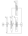
- UE 100 includes communication unit 110 and control unit 120 .
- the communication unit 110 performs wireless communication with the base station 200 by transmitting and receiving wireless signals to and from the base station 200 .
- the communication unit 110 has at least one transmitter 111 and at least one receiver 112 .
- the transmitter 111 and receiver 112 may be configured to include multiple antennas and RF circuits.
- the antenna converts a signal into radio waves and radiates the radio waves into space. Also, the antenna receives radio waves in space and converts the radio waves into signals.
- the RF circuitry performs analog processing of signals transmitted and received through the antenna.
- the RF circuitry may include high frequency filters, amplifiers, modulators, low pass filters, and the like.
- the control unit 120 performs various controls in the UE 100.
- Control unit 120 controls communication with base station 200 via communication unit 110 .
- the operations of the UE 100 described above and below may be operations under the control of the control unit 120 .
- the control unit 120 may include at least one processor capable of executing a program and a memory that stores the program.
- the processor may execute a program to operate the control unit 120 .
- the control unit 120 may include a digital signal processor that performs digital processing of signals transmitted and received through the antenna and RF circuitry.
- the digital processing includes processing of the protocol stack of the RAN. Note that the memory stores programs executed by the processor, parameters related to the programs, and data related to the programs.
- the memory is ROM (Read Only Memory), EPROM (Erasable Programmable Read Only Memory), EEPROM (Electrically Erasable Programmable Read Only Memory), RAM (Random Access Mem ory) and flash memory. All or part of the memory may be included within the processor.
- the UE 100 configured in this way performs time/frequency synchronization in the downlink using TRS.
- the receiving unit 112 receives a specific SIB including the TRS resource setting, and a DCI including an availability indicator indicating whether TRS is transmitted based on the TRS resource set set by the TRS resource setting. Receive from base station 200 . Based on the availability indicator, the control unit 120 determines whether TRS is transmitted based on the configured TRS resource set. The control unit 120 determines the number of bits of the availability indicator field in which the availability indicator is stored based on the number of TRS resource set groups defined by the TRS resource configuration. This allows the UE 100 to identify the availability indicator field and correctly determine whether TRS is transmitted based on the configured TRS resource set.
- the configuration of the base station 200 according to the embodiment will be described with reference to FIG.
- the base station 200 has a communication section 210 , a network communication section 220 and a control section 230 .
- the communication unit 210 receives radio signals from the UE 100 and transmits radio signals to the UE 100.
- the communication unit 210 has at least one transmitter 211 and at least one receiver 212 .
- the transmitting section 211 and the receiving section 212 may be configured including an RF circuit.
- the RF circuitry performs analog processing of signals transmitted and received through the antenna.
- the RF circuitry may include high frequency filters, amplifiers, modulators, low pass filters, and the like.
- the network communication unit 220 transmits and receives signals to and from the network.
- the network communication unit 220 receives signals from adjacent base stations connected via an Xn interface, which is an interface between base stations, and transmits signals to the adjacent base stations. Also, the network communication unit 220 receives a signal from the core network device 300 connected via the NG interface, for example, and transmits the signal to the core network device 300 .
- the control unit 230 performs various controls in the base station 200.
- the control unit 230 controls communication with the UE 100 via the communication unit 210, for example.
- the control unit 230 controls communication with a node (for example, an adjacent base station, the core network device 300) via the network communication unit 220, for example.
- the operations of the base station 200 described above and below may be operations under the control of the control unit 230 .
- the control unit 230 may include at least one processor capable of executing programs and a memory storing the programs.
- the processor may execute a program to operate the controller 230 .
- Control unit 230 may include a digital signal processor that performs digital processing of signals transmitted and received through the antenna and RF circuitry.
- the digital processing includes processing of the protocol stack of the RAN.
- the memory stores programs executed by the processor, parameters related to the programs, and data related to the programs. All or part of the memory may be included within the processor.
- the base station 200 configured in this manner performs radio communication with the UE 100 that performs time/frequency synchronization in the downlink using TRS.
- the transmission unit 211 includes an SIB including TRS resource configuration, and a DCI including an availability indicator indicating whether TRS is transmitted based on the TRS resource set configured by the TRS resource configuration. , is transmitted to the UE 100 .
- the control unit 230 determines the number of bits of the availability indicator field in which the availability indicator is stored based on the number of TRS resource set groups defined by the TRS resource configuration. This allows the UE 100 to identify the availability indicator field and correctly determine whether TRS is transmitted based on the configured TRS resource set.
- the transmission unit 211 of the base station 200 transmits a specific SIB including TRS resource settings.
- Receiving section 112 of UE 100 receives the specific SIB.
- the specific SIB may include the configuration of TRS (eg, CSI-RS) for tracking that can be used by UE 100 in RRC idle state or RRC inactive state.
- TRS eg, CSI-RS
- a specific SIB may be referred to as SIBXX.
- a specific SIB includes TRS resource settings.
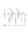
- the specific SIB includes, as TRS resource settings, a TRS resource set setting (trs-ResourceSetConfig-r17/TRS-ResourceSetConfig-r17) and an individual TRS setting list (nzp-CSI-RS-ResourceListForTracking-r17). and common TRS settings (nzp-CSI-RS-ResourceCommon-r17/NZP-CSI-RS-ResourceCommon-r17) (see E91 in FIG. 9).
- TRS resource set setting trs-ResourceSetConfig-r17/TRS-ResourceSetConfig-r17
- nzp-CSI-RS-ResourceListForTracking-r17 an individual TRS setting list
- common TRS settings nzp-CSI-RS-ResourceCommon-r17/NZP-CSI-RS-ResourceCommon-r17
- TRS-ResourceSetConfig-r17 may consist of one or more TRS resource set groups (TRS-ResourceSetGroup-r17) (see E92 in FIG. 9).
- the TRS resource set configuration may be configured in a list format containing TRS resource set groups.
- a TRS resource set configuration may define a TRS resource set group.
- a TRS resource set group may be a list of TRS resource sets (NZP-CSI-RS-ResourceSetSIB-r17) (see E93 in FIG. 9). Therefore, a TRS resource set group consists of grouped TRS resource sets. That is, the TRS resource set configuration may be a parameter for grouping TRS resource sets.
- a TRS resource set may be a set of a TRS resource set identifier (nzp-CSI-ResourceSetId-r17/NZP-CSI-RS-ResourceSetId) and a TRS resource (nzp-CSI-RS-Resources-r17).
- the TRS resource may be a list of TRS resource identifiers (NZP-CSI-RS-ResourceId) associated with the TRS resource.
- the individual TRS setting list is a list of individual TRS settings (NZP-CSI-RS-ResourceSIB-r17). As shown in FIG. 10, the individual TRS setting includes the identifier of the TRS resource (nzp-CSI-RS-ResourceId/NZP-CSI-RS-ResourceId), a parameter indicating the allocation of the TRS in the frequency direction (frequencyDomainAllocation), It may include a parameter (firstOFDMSymbolInTimeDomain) indicating TRS allocation in the time direction and a parameter (scramblingID/ScramblingId) indicating a scrambling identifier of TRS.
- a common TRS setting may be a set of parameters commonly applied to all individual TRS settings.
- the common TRS settings include a parameter (csi-FrequencyOccupation-r17/CSI-FrequencyOccupation) indicating the occupied range of the TRS in the frequency direction, and a parameter (powerControlOffsetSS-r17) indicating the power offset of the TRS with respect to the synchronization signal.
- a parameter indicating the periodicity and time offset of the TRS (periodicityAndOffset-r17/CSI-ResourcePeriodicityAndOffsetSIB-r17), and a parameter related to QCL of the TRS (qcl-InfoForTracking-r17).
- the control unit 120 of the UE 100 determines the number of bits in the availability indicator field. Specifically, the control unit 120 of the UE 100 determines the number of bits of the availability indicator field based on the number of TRS resource set groups. If the TRS resource set configuration is configured in a list format including TRS resource set groups, the control unit 120 of the UE 100 is based on the number of one or more TRS resource set group entries in the list format, availability indicator Determines the number of bits in the field. When the number of entries in the TRS resource set group (which may be the entry size) is N, the control unit 120 of the UE 100 determines that the number of bits of the availability indicator field is N.
- step S103 the transmission unit 211 of the base station 200 transmits DCI to the UE100.
- Receiving section 112 of UE 100 receives the DCI from base station 200 .
- the DCI may be DCI format 1_0 used for PDSCH scheduling in one downlink cell.
- DCI format 1_0 may include an availability indicator (TRS availability indication) (see E111 in FIG. 11).
- TRS availability indication may be stored in the availability indicator field within DCI format 1_0.
- the availability indicator may be sent by DCI format 1_0 CRC-scrambled with the Paging-Radio Network Temporary Identifier (P-RNTI).
- P-RNTI Paging-Radio Network Temporary Identifier
- the availability indicator is a bitmap of any number of bits from 1 to 6 when the TRS resource set configuration (TRS-ResourceSetConfig) is set. Therefore, the availability indicator field is indicated by any number of bits from 1 to 6. On the other hand, the availability indicator (ie, availability indicator field) is 0 bit if the TRS resource set configuration is not set.
- the bit positions of the bitmap that make up the availability indicator are associated with the TRS resource set group entries that are made up of the TRS resource set settings.
- the first or leftmost bit corresponds to the first entry in the TRS resource set group configured in the TRS resource set configuration
- the second bit corresponds to the TRS resource configured in the TRS resource set configuration.
- the number of bits in the availability indicator field corresponds to the number of TRS resource set groups configured by the TRS resource set configuration.
- the DCI may be DCI format 2_7 used to notify one or more UEs 100 of a paging early indicator and an availability indicator.
- DCI format 2_7 may include an availability indicator (see E112 in FIG. 11).
- the availability indicator may be stored in the availability indicator field within DCI format 2_7.
- the availability indicator may be sent by DCI format 2_7 CRC-scrambled with Paging Early Indicator-Radio Network Temporary Identifier (PEI-RNTI).
- PEI-RNTI Paging Early Indicator-Radio Network Temporary Identifier
- step S104 the control unit 120 of the UE 100 determines whether TRS is transmitted.
- the control unit 120 of the UE 100 identifies the availability indicator (or availability indicator field) based on the determined number of bits of the availability indicator. The control unit 120 determines whether or not the TRS is transmitted based on the specified availability indicator.
- the control unit 120 of the UE 100 if the value at the bit position of the bitmap that constitutes the availability indicator is a predetermined value (for example, "1"), the TRS of the TRS resource set group of the corresponding entry is Determine that it has been sent. On the other hand, when the value at the bit position is a value different from the predetermined value (for example, "0"), the control unit 120 determines that the TRS of the TRS resource set group of the corresponding entry has not been transmitted.
- a predetermined value for example, "1”
- Control unit 120 determines whether TRS is being transmitted based on the set TRS resource set based on the value of the bit position corresponding to the entry of the TRS resource set group to which the TRS resource set set in UE 100 belongs. judge. When determining that the TRS is transmitted based on the set TRS resource set, the control unit 120 executes the process of step S105. UE100 does not need to perform the process of step S105, when it determines with TRS not being transmitted. In this case, the UE 100 may perform processing for receiving the SSB.
- Steps S105 and S106 correspond to steps S23 and S24.
- the transmitting unit 211 of the base station 200 transmits the SIB including the TRS resource configuration and the availability indicator indicating whether or not the TRS is transmitted based on the TRS resource set configured by the TRS resource configuration. and the DCI containing are transmitted to the UE 100 .
- the control unit 230 of the base station 200 determines the number of bits of the availability indicator field in which the availability indicator is stored, based on the number of TRS resource set groups defined by the TRS resource configuration.
- the receiving unit 112 of the UE 100 transmits the SIB including the TRS resource configuration and the DCI including the availability indicator indicating whether or not the TRS is transmitted based on the TRS resource set configured by the TRS resource configuration to the base station 200.
- the control unit 120 determines whether TRS is transmitted based on the configured TRS resource set.
- the control unit 120 determines the number of bits of the availability indicator field in which the availability indicator is stored based on the number of TRS resource set groups defined by the TRS resource configuration. This allows the UE 100 to identify the availability indicator field and correctly determine whether TRS is transmitted based on the configured TRS resource set.
- the TRS resource settings may include TRS resource set settings configured by one or more TRS resource set groups.
- the control unit 120 may determine the number of bits of the availability indicator field based on the number of TRS resource set groups making up the TRS resource set configuration.
- the control unit 120 can determine the number of bits of the availability indicator field by setting the TRS resource set, and can correctly determine whether or not the TRS is transmitted based on the set TRS resource set.
- the TRS resource set configuration may be configured in a list format including one or more TRS resource set groups.
- the control unit 120 may determine the number of bits of the availability indicator field based on the number of entries of one or more TRS resource set groups in list format. As a result, even if the TRS resource set configuration does not include an identifier for identifying a group, the control unit 120 can determine the number of bits in the availability indicator field and reduce the amount of information in the TRS resource configuration.
- bit positions of the bitmap that constitutes the availability indicator may be associated with the entry.
- the control unit 120 may determine that the TRS of the TRS resource set group of the corresponding entry is transmitted. This allows the control unit 120 to determine whether TRS is being transmitted based on the TRS resource set included in the TRS resource set group of the corresponding entry. As a result, it is possible to prevent the UE 100 from trying to receive the TRS even though the TRS has not been transmitted.
- the UE 100 determines the number of bits of the availability indicator field based on the group identifier.
- the transmission unit 211 of the base station 200 transmits the following specific SIB.
- Receiving section 112 of UE 100 receives the specific SIB.
- the TRS resource set configuration (trs-ResourceSetConfig-r17) included in the specific SIB may be a list of TRS resource sets (NZP-CSI-RS-ResourceSetSIB-r17) (E121 in FIG. 12 reference).
- the TRS resource set identifies a TRS resource set identifier (nzp-CSI-ResourceSetId-r17/NZP-CSI-RS-ResourceSetId), a TRS resource (nzp-CSI-RS-Resources-r17), and a TRS resource set group. and a group identifier (trs-ResourceSetGroupId-r17) (see E122 in FIG. 12).
- each TRS resource set group is composed of TRS resource sets having the same corresponding group identifier value.
- the base station 200 (network 10) configures a TRS resource set group with consecutive IDs starting from 0.
- the control unit 120 of the UE 100 determines the number of bits of the availability indicator field based on the number of group identifiers. When the number of group identifiers is N, the control unit 120 determines that the number of bits of the availability indicator field is N.
- each code point of the "availability indicator" in the DCI field ie the bit position of the bitmap of the availability indicator, is associated with the TRS resource set group ID.
- the first or leftmost bit of the bitmap that constitutes the availability indicator corresponds to TRS resource set group ID 0, and the second bit corresponds to TRS resource set group ID 1 (E131 in FIG. 13). and E132).
- step S104 the control unit 120 of the UE 100 is based on the set TRS resource set based on the value of the bit position corresponding to the group identifier that identifies the TRS resource set group to which the TRS resource set set in the UE 100 belongs. Determine whether a TRS has been sent.
- the TRS resource setting may include a TRS resource set setting made up of one or more TRS resource sets associated with a group identifier.
- the control unit 120 may determine the number of bits of the availability indicator field based on the number of group identifiers. This allows the UE 100 to identify the availability indicator field and correctly determine whether TRS is transmitted based on the configured TRS resource set.
- a third operation example will be described with reference to FIGS. 8 and 14 . Descriptions similar to those of the above operation example are omitted as appropriate.
- one or more TRS resource set groups and group identifiers are associated in a format different from that of the second operation example.
- the specific SIB includes TRS resource settings, as in the first operation example.
- TRS resource set configuration trs-ResourceSetConfig-r17/TRS-ResourceSetConfig-r17
- TRS-ResourceSetGroup-r17 one or more TRS resource set groups
- trs-ResourceSetGroupId-r17 group identifier
- the TRS resource settings include TRS resource set settings associated with one or more TRS resource set groups and group identifiers.
- step S102 the control unit 120 of the UE 100 determines the number of bits of the availability indicator field based on the number of group identifiers, as in the second operation example. This allows the UE 100 to identify the availability indicator field and correctly determine whether TRS is transmitted based on the configured TRS resource set.
- the TRS resource configuration includes separate TRS resource set groups for normal UEs and eDRX UEs performing DRX.
- step S201 the transmission unit 211 of the base station 200 transmits the following specific SIB.
- the specific SIB includes a first TRS resource set group for general UEs performing DRX and a second TRS resource set group for eDRX UEs performing eDRX.
- different group identifiers are assigned to the first TRS resource set group and the second TRS resource set group.
- the first TRS resource set group includes a TRS resource set group configured by a TRS resource set associated with group identifier #0 and a TRS associated with group identifier #1. and a TRS resource set group composed of resource sets.
- the second TRS resource set includes a TRS resource set group made up of TRS resource sets associated with group identifier #2.
- Each TRS resource set associated with group identifier #0 and group identifier #1 is a normal TRS resource set for UEs.
- Each TRS resource set associated with group identifier #2 is a TRS resource set for eDRX UEs.
- a specific SIB may contain a group identifier and information indicating whether the TRS resource set associated with the group identifier is for eDRX UEs (or for normal UEs).
- each TRS resource set may be associated with information indicating whether the TRS resource set is for eDRX UEs (or for normal UEs).
- the group identifier may be associated with information indicating whether the TRS resource set associated with the group identifier is for eDRX UEs (or for normal UEs). Based on this information, the control unit 120 of the UE 100 can determine whether each TRS resource set is for normal UEs or for eDRX UEs.
- the specific SIB may contain duration information indicating the validity duration of the availability indicator indicated in the availability indicator field for each of the first TRS resource set and the second TRS resource set.
- the period information includes first period information that is the validity period of the availability indicator for the first TRS resource set and second period information that is the validity period of the availability indicator for the second TRS resource set; may contain
- the control unit 120 can determine the validity period of the availability indicator for the first TRS resource set based on the first duration information. Similarly, the control unit 120 can determine the validity period of the availability indicator for the second TRS resource set based on the second period information.
- the validity period for the first TRS resource set may be an integer multiple of the first time unit.
- the first time unit may be, for example, one default paging cycle.
- the validity period for the second TRS resource set may be an integer multiple of a second time unit longer than the first time unit.
- the first time unit may be, for example, an eDRX cycle, or an acquisition period (specifically, an eDRX acquisition period) that triggers the UE 100 in which eDRX is configured to acquire an updated SIB. good too.
- the control unit 120 of the UE 100 determines the number of bits in the availability indicator field.
- the control unit 120 determines the number of bits of the availability indicator field based on the total number of the first TRS resource set group and the second TRS resource set group.
- control unit 120 may determine the number of bits of the availability indicator field based on the total number of group identifiers of the first TRS resource set group and the second TRS resource set group. In the example of FIG. 16, the control unit 120 controls the total number of 2, which is the number of group identifiers of the first TRS resource set group, and 1, which is the number of group identifiers of the second TRS resource set group (that is, total value) of 3 may be determined as the number of bits in the availability indicator field.
- Steps S203 to S206 are the same as steps S103 to S106.
- the control unit 120 when the first TRS resource set associated with the group identifier #0 is set, the control unit 120, based on the value of the first bit position of the bitmap constituting the availability indicator, the TRS is transmitted. Similarly, the control unit 120, for example, when the second TRS resource set associated with the group identifier # 2 is set, based on the value of the third bit position of the bitmap constituting the availability indicator , TRS is transmitted.
- the control unit 120 receives TRS based on the first TRS resource set. If the UE 100 is an eDRX UE, the control unit 120 receives TRS based on the second TRS resource set. For example, when the DRX setting is set (for example, the DRX cycle is applied), the control unit 120 determines that the UE 100 is a normal UE. On the other hand, the control unit 120 determines that the UE 100 is an eDRX UE, for example, when the eDRX setting is set (for example, the eDRX cycle is applied).
- the control unit 120 may determine the number of bits of the availability indicator field based on the total number of the first TRS resource set group and the second TRS resource set group. Also, the control unit 120 may determine the number of bits of the availability indicator field based on the total number of group identifiers of the first TRS resource set group and the second TRS resource set group.
- the specific SIB includes a TRS resource set for general UEs performing DRX and a TRS resource set for eDRX UEs performing eDRX
- the UE 100 can specify the availability indicator field, It can correctly determine whether TRS is transmitted based on the configured TRS resource set.
- the base station 200 transmits based on the first TRS resource set. For each TRS and TRS transmitted based on the second set of TRS resources, it can be determined whether to transmit or not. This allows the base station 200 to flexibly control TRS transmission.
- the receiving unit 112 receives from the base station 200 a specific SIB including period information indicating the valid period of the availability indicator for each of the first TRS resource set and the second TRS resource set.
- the control unit 120 controls the It is possible to know the validity period of the availability indicator for each.
- the UE 100 can correctly determine whether TRS is transmitted based on the set TRS resource set.
- a fifth operation example will be described with reference to FIG. Descriptions similar to those of the above operation example are omitted as appropriate.
- the UE 100 determines the number of bits in the availability indicator field based on the total number of groups having the largest number of the first TRS resource set group and the second TRS resource set group.
- group identifiers are individually assigned to the first TRS resource set group and the second TRS resource set group.
- the first TRS resource set group includes a TRS resource set group configured by a TRS resource set associated with group identifier #0, and a TRS resource set associated with group identifier #1. and a TRS resource set group composed of resource sets.
- the second TRS resource set includes a TRS resource set group made up of TRS resource sets associated with group identifier #0.
- Each TRS resource set associated with group identifier #0 and group identifier #1 is a normal TRS resource set for UEs.
- Each TRS resource set associated with group identifier #0 is a TRS resource set for eDRX UEs.
- the control unit 120 of the UE 100 may determine the number of bits of the availability indicator field based on the total number of groups having the largest number of the first TRS resource set group and the second TRS resource set group.
- the control unit 120 may determine the number of bits of the availability indicator field based on the total number of group identifiers of the large number of groups.
- the control unit 120 compares 2, which is the number of group identifiers of the first TRS resource set group, with 1, which is the number of group identifiers of the second TRS resource set group, and It is determined that the number of group identifiers in one TRS resource set group is large.
- the control unit 120 may determine 2, which is the number of group identifiers of the first TRS resource set group having the largest number, as the number of bits of the availability indicator field.
- the control unit 120 may determine the number of bits of the availability indicator field based on the total number of groups having the largest number of the first TRS resource set group and the second TRS resource set group. . Also, the control unit 120 may determine the number of bits of the availability indicator field based on the total number of group identifiers with a large number. As a result, even when the specific SIB includes a TRS resource set for general UEs performing DRX and a TRS resource set for eDRX UEs performing eDRX, the UE 100 can specify the availability indicator field, It can correctly determine whether TRS is transmitted based on the configured TRS resource set.
- base station 200 determines the number of TRS resource set groups to which group identifiers are assigned. can be increased compared to the fourth operation example. This allows the base station 200 to finely configure the TRS resource settings.
- the control unit 230 of the base station 200 assigns the same group identifier (for example, group identifier #0 in FIG. 16) to the first TRS resource set group and the second TRS resource set group. If so, for TRSs transmitted based on the first TRS resource set and the second TRS resource set assigned the same group identifier, determine whether to transmit both TRSs or not to transmit both TRSs. do. That is, the control unit 230 of the base station 200 does not perform control of transmitting TRS based on one TRS resource set and not transmitting TRS based on the other TRS resource set.
- group identifier for example, group identifier #0 in FIG. 16
- the control unit 120 of the UE 100 may perform the following processing based on the reception of the specific SIB, for example.
- step S301 the control unit 120 of the UE 100 determines whether the UE 100 is an eDRX UE. If the UE 100 is an eDRX UE, the control unit 120 executes the process of step S302. On the other hand, if the UE 100 is not an eDRX UE, the control unit 120 may end the process.
- control unit 120 may determine that the UE 100 is an eDRX UE, for example, when the eDRX setting is set (for example, the eDRX cycle is applied). The control unit 120 may determine that the UE 100 is not an eDRX UE when DRX settings are configured (for example, a DRX cycle is applied).
- step S302 the control unit 120 determines whether or not the specific SIB includes second period information indicating the validity period of the availability indicator for the second TRS resource set. If the specific SIB includes the second period information, control unit 120 executes the process of step S303. If the specific SIB does not contain the second period information, control unit 120 executes the process of step S304.
- step S303 the control unit 120 determines the validity period based on the second period information.
- control unit 120 may determine the validity period based on the eDRX cycle or the eDRX acquisition cycle that triggers the eDRX UE to acquire the updated SIB.
- the control unit 120 may, for example, consider the period until the next eDRX cycle as the valid period as a default setting. Alternatively, the control unit 120 may, for example, regard the interval up to the boundary of the acquisition cycle as the effective period as a default setting.
- the control unit 120 determines the validity period based on the second period information. You can If the specific SIB does not include the second period information, the control unit 120 may determine the valid period based on the eDRX cycle or the eDRX acquisition period. Thereby, the UE 100 can appropriately determine the valid period regardless of the presence or absence of the second period information in the specific SIB. As a result, the control unit 120 can correctly determine whether the TRS is transmitted based on the set TRS resource set.
- the operation sequences (and operation flows) in the above-described embodiments do not necessarily have to be executed in chronological order according to the order described in the flow diagrams or sequence diagrams. For example, the steps in the operations may be performed out of order or in parallel with the order illustrated in the flow diagrams or sequence diagrams. Also, some steps in the operation may be omitted and additional steps may be added to the process. Further, the operation sequences (and operation flows) in the above-described embodiments may be implemented independently, or two or more operation sequences (and operation flows) may be combined and implemented. For example, some steps of one operation flow may be added to another operation flow, or some steps of one operation flow may be replaced with some steps of another operation flow.
- the mobile communication system 1 based on NR has been described as an example.
- the mobile communication system 1 is not limited to this example.
- the mobile communication system 1 may be a TS-compliant system of either LTE (Long Term Evolution) or another generation system (for example, 6th generation) of the 3GPP standards.
- Base station 200 may be an eNB that provides E-UTRA user plane and control plane protocol termination towards UE 100 in LTE.
- the mobile communication system 1 may be a system conforming to a TS of a standard other than the 3GPP standard.
- the base station 200 may be an IAB (Integrated Access and Backhaul) donor or an IAB node.
- IAB Integrated Access and Backhaul
- a program that causes a computer to execute each process performed by the UE 100 or the base station 200 may be provided.
- the program may be recorded on a computer readable medium.
- a computer readable medium allows the installation of the program on the computer.
- the computer-readable medium on which the program is recorded may be a non-transitory recording medium.
- the non-transitory recording medium is not particularly limited, but may be, for example, a recording medium such as CD-ROM (Compact Disk Read Only Memory) or DVD-ROM (Digital Versatile Disc Read Only Memory). good.
- circuits that execute each process performed by the UE 100 or the base station 200 may be integrated, and at least a part of the UE 100 or the base station 200 may be configured as a semiconductor integrated circuit (chipset, SoC (System On Chip)).
- “transmit” may mean performing at least one layer of processing in the protocol stack used for transmission, or physically transmitting the signal wirelessly or by wire. It may mean sending to Alternatively, “transmitting” may mean a combination of performing the at least one layer of processing and physically transmitting the signal wirelessly or by wire.
- “receive” may mean performing processing of at least one layer in the protocol stack used for reception, or physically receiving a signal wirelessly or by wire. may mean that Alternatively, “receiving” may mean a combination of performing the at least one layer of processing and physically receiving the signal wirelessly or by wire.
- “obtain/acquire” may mean obtaining information among stored information, and may mean obtaining information among information received from other nodes.
- references to "based on” and “depending on/in response to” are used unless otherwise specified. does not mean The phrase “based on” means both “based only on” and “based at least in part on.” Similarly, the phrase “depending on” means both “only depending on” and “at least partially depending on.” Similarly, “include” and “comprise” are not meant to include only the recited items, and may include only the recited items or in addition to the recited items. Means that it may contain further items. Similarly, in the present disclosure, “or” does not mean exclusive OR, but means logical OR. Furthermore, any references to elements using the "first,” “second,” etc.
- a receiver that receives a system information block (SIB) from a base station; a control unit that determines the number of bits in a bitmap of a tracking reference signal (TRS) availability indicator in downlink control information (DCI); The control unit If the SIB contains a TRS resource set configuration that is a list of TRS resource sets, determine the number of bits based on an identifier associated with the TRS resource set; A communications device that determines the number of bits to be 0 if the TRS resource set configuration is not included in the SIB.
- SIB system information block
- TRS tracking reference signal
- the receiving unit receives the DCI from the base station, 5.
- the communication device according to any one of appendices 1 to 4, wherein the control unit identifies the availability indicator of the received DCI based on the determined number of bits.
- SIB system information block
- TRS tracking reference signal
- a communication method performed by a communication device comprising: receiving a system information block (SIB) from a base station; determining the number of bits in a bitmap of a tracking reference signal (TRS) availability indicator in downlink control information (DCI); In the determining step, If the SIB contains a TRS resource set configuration that is a list of TRS resource sets, determine the number of bits based on an identifier associated with the TRS resource set; determining that the number of bits is 0 if the TRS resource set configuration is not included in the SIB.
- SIB system information block
- TRS tracking reference signal
Abstract
A communication device (100) comprises: a reception unit that receives a system information block (SIB) from a base station (200); and a control unit (120) that determines the number of bits in an availability indicator bitmap of a tracking reference signal (TRS) in downlink control information (DCI). If a TRS resource set configuration, which is a TRS resource set list, is included in the SIB, the control unit (120) determines the number of bits on the basis of an identifier corresponding to the TRS resource set. If the TRS resource set configuration is not included in the SIB, the control unit (120) determines the number of bits to be zero.
Description
本出願は、2022年1月7日に出願された特許出願番号2022-001588号に基づくものであって、その優先権の利益を主張するものであり、その特許出願のすべての内容が、参照により本明細書に組み入れられる。
This application is based on and claims the benefit of priority from patent application number 2022-001588, filed January 7, 2022, the entire contents of which are incorporated by reference. incorporated herein by.
本開示は、移動通信システムで用いる、通信装置、基地局及び通信方法に関する。
The present disclosure relates to a communication device, base station and communication method used in a mobile communication system.
移動通信システムの標準化プロジェクトである3GPP(登録商標。以下同じ)(3rd Generation Partnership Project)の技術仕様に準拠する移動通信システムにおいて、無線リソース制御(RRC)コネクティッド状態にある通信装置に対して、通信装置個別に設定される参照信号(RS)に、トラッキング参照信号(TRS:Tracking Reference Signal)がある。TRSは、時間・周波数同期(時間・周波数トラッキング)を行うための参照信号である。
In a mobile communication system that complies with the technical specifications of the 3GPP (registered trademark; hereinafter the same) (3rd Generation Partnership Project), which is a standardization project for mobile communication systems, for a communication device in a radio resource control (RRC) connected state, A tracking reference signal (TRS) is a reference signal (RS) that is set for each communication device. TRS is a reference signal for performing time/frequency synchronization (time/frequency tracking).
3GPPにおいて、RRCアイドル状態又はRRCインアクティブ状態にある通信装置向けに消費電力を削減するための技術の標準化に向けた議論が行われている。このような技術において、RRCコネクティッド状態にある通信装置に向けて設定されたTRSリソース(「TRS機会」とも称される)を、RRCアイドル状態又はRRCインアクティブ状態にある通信装置においても利用可能とすることが検討されている(例えば、非特許文献1参照)。具体的には、基地局は、TRSリソース設定をシステム情報ブロック(「報知情報」とも称される)によってブロードキャストする。
3GPP is discussing standardization of techniques for reducing power consumption for communication devices in RRC idle state or RRC inactive state. In such technology, TRS resources (also referred to as "TRS opportunities") configured for communication devices in RRC connected state can be used by communication devices in RRC idle state or RRC inactive state. (For example, see Non-Patent Document 1). Specifically, the base station broadcasts the TRS resource configuration via system information blocks (also referred to as “broadcast information”).
RRCアイドル状態又はRRCインアクティブ状態にある通信装置は、システム情報ブロックにより設定されたTRSリソース設定を用いてTRSを受信することにより、SSB(SS/PBCH Block)を受信しなくても同期を取ることができ、同期を確立してからページングを監視するまでのウェイクアップ持続時間を短縮し得る。そして、SSBを受信しないことにより、SSBの受信に伴う消費電力の増加が抑制される。
A communication device in RRC idle state or RRC inactive state receives TRS using the TRS resource configuration set by the system information block, thereby synchronizing without receiving SSB (SS/PBCH Block). can reduce the wake-up duration between establishing synchronization and monitoring paging. By not receiving the SSB, an increase in power consumption due to the reception of the SSB is suppressed.
基地局は、TRSリソース設定により設定されたTRSリソースセットに基づいて前記TRSが送信されるか否かを示す可用性指示子を含む下りリンク制御情報(Downlink Control Information:DCI)を通信装置へ送信する。通信装置は、可用性指示子に基づいて、設定されたTRSリソースセットに基づいてTRSが送信されるか否かを判定する(例えば、非特許文献1参照)。なお、可用性指示子が格納される可用性指示子フィールドは、最大6ビットで示される可変長フィールドである。
The base station transmits downlink control information (DCI) including an availability indicator indicating whether or not the TRS is transmitted based on the TRS resource set configured by the TRS resource configuration to the communication device. . Based on the availability indicator, the communication device determines whether TRS is transmitted based on the configured TRS resource set (see, for example, Non-Patent Document 1). Note that the availability indicator field in which the availability indicator is stored is a variable length field indicated by a maximum of 6 bits.
第1の態様に係るユーザ装置は、システム情報ブロック(SIB)を基地局から受信する受信部と、下りリンク制御情報(DCI)におけるトラッキング参照信号(TRS)の可用性指示子のビットマップのビット数を決定する制御部と、を備える。前記制御部は、TRSリソースセットのリストであるTRSリソースセット設定が前記SIBに含まれている場合、前記TRSリソースセットに対応付けられた識別子に基づいて、前記ビット数を決定し、前記TRSリソースセット設定が前記SIBに含まれていない場合、前記ビット数を0と決定する。
A user equipment according to a first aspect includes a receiving unit that receives a system information block (SIB) from a base station, and the number of bits of a bitmap of a tracking reference signal (TRS) availability indicator in downlink control information (DCI) and a control unit that determines When the SIB includes a TRS resource set setting that is a list of TRS resource sets, the control unit determines the number of bits based on an identifier associated with the TRS resource set, and the TRS resource If the set configuration is not included in the SIB, determine the number of bits as zero.
第2の態様に係る基地局は、システム情報ブロック(SIB)を送信する送信部と、下りリンク制御情報(DCI)におけるトラッキング参照信号(TRS)の可用性指示子のビットマップのビット数を決定する制御部と、を備える。前記制御部は、TRSリソースセットのリストであるTRSリソースセット設定を前記SIBに含めない場合、前記TRSリソースセットに対応付けられた識別子に基づく前記ビット数を決定し、前記TRSリソースセット設定を前記SIBに含めない場合、前記ビット数を0と決定する。
A base station according to the second aspect determines the number of bits of a bitmap of a tracking reference signal (TRS) availability indicator in downlink control information (DCI) and a transmission unit that transmits a system information block (SIB). and a control unit. If the SIB does not include a TRS resource set configuration that is a list of TRS resource sets, the control unit determines the number of bits based on an identifier associated with the TRS resource set, and sets the TRS resource set configuration to the If not included in the SIB, the number of bits is determined to be 0.
第3の態様に係る通信方法は、通信装置で実行される通信方法である。前記通信方法は、システム情報ブロック(SIB)を基地局から受信するステップと、下りリンク制御情報(DCI)におけるトラッキング参照信号(TRS)の可用性指示子のビットマップのビット数を決定するステップと、を備える。前記決定するステップでは、TRSリソースセットのリストであるTRSリソースセット設定が前記SIBに含まれている場合、前記TRSリソースセットに対応付けられた識別子に基づいて、前記ビット数を決定し、前記TRSリソースセット設定が前記SIBに含まれていない場合、前記ビット数を0と決定する。
A communication method according to the third aspect is a communication method executed by a communication device. The communication method comprises the steps of receiving a system information block (SIB) from a base station, determining a number of bits of a tracking reference signal (TRS) availability indicator bitmap in downlink control information (DCI); Prepare. In the determining step, if a TRS resource set configuration, which is a list of TRS resource sets, is included in the SIB, the number of bits is determined based on an identifier associated with the TRS resource set, and the TRS If resource set configuration is not included in the SIB, determine the number of bits to be zero.
本開示についての目的、特徴、及び利点等は、添付の図面を参照しながら下記の詳細な記述により、より明確になる。
図1は、実施形態に係る移動通信システムの構成を示す図である。
図2は、実施形態に係る移動通信システムにおけるプロトコルスタックの構成例を示す図である。
図3は、eDRXの概要を説明するための図である。
図4は、RRCアイドル状態又はRRCインアクティブ状態にあるUEについての動作例を示すシーケンス図である。
図5は、RRCアイドル状態又はRRCインアクティブ状態にあるUEがTRSを受信するための動作例を示すシーケンス図である。
図6は、実施形態に係るUEの構成を示す図である。
図7は、実施形態に係る基地局の構成を示す図である。
図8は、実施形態に係る第1動作例を説明するためのシーケンス図である。
図9は、実施形態に係る第1動作例を説明するための説明図(その1)である。
図10は、実施形態に係る第1動作例を説明するための説明図(その2)である。
図11は、実施形態に係る第1動作例を説明するための説明図(その3)である。
図12は、実施形態に係る第2動作例を説明するための説明図(その1)である。
図13は、実施形態に係る第2動作例を説明するための説明図(その2)である。
図14は、実施形態に係る第3動作例を説明するための説明図である。
図15は、実施形態に係る第4動作例を説明するためのシーケンス図である。
図16は、実施形態に係る第4動作例を説明するための説明図である。
図17は、実施形態に係る第5動作例を説明するための説明図である。
図18は、実施形態に係る第6動作例を説明するためのフローチャートである。
Objects, features, advantages, etc. of the present disclosure will become clearer from the following detailed description with reference to the accompanying drawings.
FIG. 1 is a diagram showing the configuration of a mobile communication system according to an embodiment. FIG. 2 is a diagram showing a configuration example of a protocol stack in the mobile communication system according to the embodiment. FIG. 3 is a diagram for explaining an overview of eDRX. FIG. 4 is a sequence diagram illustrating an example operation for a UE in RRC idle state or RRC inactive state. FIG. 5 is a sequence diagram illustrating an example operation for a UE in RRC idle state or RRC inactive state to receive a TRS. FIG. 6 is a diagram showing the configuration of the UE according to the embodiment. FIG. 7 is a diagram showing the configuration of a base station according to the embodiment. FIG. 8 is a sequence diagram for explaining the first operation example according to the embodiment. FIG. 9 is an explanatory diagram (part 1) for explaining the first operation example according to the embodiment; FIG. 10 is an explanatory diagram (part 2) for explaining the first operation example according to the embodiment; FIG. 11 is an explanatory diagram (part 3) for explaining the first operation example according to the embodiment; FIG. 12 is an explanatory diagram (part 1) for explaining a second operation example according to the embodiment; FIG. 13 is an explanatory diagram (part 2) for explaining the second operation example according to the embodiment; FIG. 14 is an explanatory diagram for explaining a third operation example according to the embodiment. FIG. 15 is a sequence diagram for explaining a fourth operation example according to the embodiment. FIG. 16 is an explanatory diagram for explaining a fourth operation example according to the embodiment. FIG. 17 is an explanatory diagram for explaining a fifth operation example according to the embodiment. FIG. 18 is a flowchart for explaining a sixth operation example according to the embodiment;
図面を参照しながら、実施形態に係る移動通信システムについて説明する。図面の記載において、同一又は類似の部分には同一又は類似の符号を付している。
A mobile communication system according to an embodiment will be described with reference to the drawings. In the description of the drawings, the same or similar parts are denoted by the same or similar reference numerals.
現状の3GPP仕様書では、通信装置が可用性指示子フィールドのビット数を決定する方法が規定されていない。その結果、通信装置が、可用性指示子フィールドを誤って特定して、設定されたTRSリソースセットに基づいてTRSが送信されるか否かを正しく判定できない虞がある。そこで、本開示は、設定されたTRSリソースセットに基づいてTRSが送信されるか否かを正しく判定可能とする通信装置、基地局及び通信方法を提供することを目的の一つとする。
The current 3GPP specifications do not define how communication devices determine the number of bits in the availability indicator field. As a result, the communication device may incorrectly identify the availability indicator field and fail to correctly determine whether a TRS will be transmitted based on the configured TRS resource set. Therefore, one object of the present disclosure is to provide a communication device, a base station, and a communication method that can correctly determine whether or not a TRS is transmitted based on a set TRS resource set.
(移動通信システムの構成)
図1を参照して、実施形態に係る移動通信システム1の構成について説明する。移動通信システム1は、例えば、3GPPの技術仕様(Technical Specification:TS)に準拠したシステムである。以下において、移動通信システム1として、3GPP規格の第5世代システム(5th Generation System:5GS)、すなわち、NR(New Radio)に基づく移動通信システムを例に挙げて説明する。 (Configuration of mobile communication system)
A configuration of amobile communication system 1 according to an embodiment will be described with reference to FIG. The mobile communication system 1 is, for example, a system conforming to 3GPP Technical Specifications (TS). Hereinafter, as the mobile communication system 1, a mobile communication system based on the 3GPP standard 5th Generation System (5GS), that is, NR (New Radio) will be described as an example.
図1を参照して、実施形態に係る移動通信システム1の構成について説明する。移動通信システム1は、例えば、3GPPの技術仕様(Technical Specification:TS)に準拠したシステムである。以下において、移動通信システム1として、3GPP規格の第5世代システム(5th Generation System:5GS)、すなわち、NR(New Radio)に基づく移動通信システムを例に挙げて説明する。 (Configuration of mobile communication system)
A configuration of a
移動通信システム1は、ネットワーク10と、ネットワーク10と通信するユーザ装置(User Equipment:UE)100とを有する。ネットワーク10は、5Gの無線アクセスネットワークであるNG-RAN(Next Generation Radio Access Network)20と、5Gのコアネットワークである5GC(5G Core Network)30とを含む。
The mobile communication system 1 has a network 10 and user equipment (UE) 100 communicating with the network 10 . The network 10 includes an NG-RAN (Next Generation Radio Access Network) 20, which is a 5G radio access network, and a 5GC (5G Core Network) 30, which is a 5G core network.
UE100は、通信装置の一例である。UE100は、移動可能な無線通信装置であってよい。UE100は、ユーザにより利用される装置であってよい。UE100は、3GPPの技術仕様で規定されるユーザ装置であってよい。UE100は、例えば、スマートフォンなどの携帯電話端末、タブレット端末、ノートPC、通信モジュール、又は通信カードなどの移動可能な装置である。UE100は、車両(例えば、車、電車など)又はこれに設けられる装置であってよい。UE100は、車両以外の輸送機体(例えば、船、飛行機など)又はこれに設けられる装置であってよい。UE100は、センサ又はこれに設けられる装置であってよい。なお、UE100は、移動局、移動端末、移動装置、移動ユニット、加入者局、加入者端末、加入者装置、加入者ユニット、ワイヤレス局、ワイヤレス端末、ワイヤレス装置、ワイヤレスユニット、リモート局、リモート端末、リモート装置、又はリモートユニット等の別の名称で呼ばれてもよい。
The UE 100 is an example of a communication device. The UE 100 may be a mobile wireless communication device. UE 100 may be a device used by a user. The UE 100 may be a user equipment defined by 3GPP technical specifications. The UE 100 is, for example, a portable device such as a mobile phone terminal such as a smart phone, a tablet terminal, a notebook PC, a communication module, or a communication card. The UE 100 may be a vehicle (eg, car, train, etc.) or a device provided therein. The UE 100 may be a transport body other than a vehicle (for example, a ship, an airplane, etc.) or a device provided thereon. The UE 100 may be a sensor or a device attached thereto. Note that the UE 100 includes a mobile station, a mobile terminal, a mobile device, a mobile unit, a subscriber station, a subscriber terminal, a subscriber device, a subscriber unit, a wireless station, a wireless terminal, a wireless device, a wireless unit, a remote station, and a remote terminal. , remote device, or remote unit.
NG-RAN20は、複数の基地局200を含む。各基地局200は、少なくとも1つのセルを管理する。セルは、通信エリアの最小単位を構成する。例えば、1つのセルは、1つの周波数(キャリア周波数)に属し、1つのコンポーネントキャリアにより構成される。用語「セル」は、無線通信リソースを表すことがあり、UE100の通信対象を表すこともある。各基地局200は、自セルに在圏するUE100との無線通信を行うことができる。基地局200は、RANのプロトコルスタックを使用してUE100と通信する。基地局200は、UE100へ向けたNRユーザプレーン及び制御プレーンプロトコル終端を提供し、NGインターフェイスを介して5GC30に接続される。このようなNRの基地局200は、gNodeB(gNB)と称されることがある。
NG-RAN 20 includes multiple base stations 200 . Each base station 200 manages at least one cell. A cell constitutes the minimum unit of a communication area. For example, one cell belongs to one frequency (carrier frequency) and is configured by one component carrier. The term “cell” may represent a radio communication resource and may also represent a communication target of UE 100 . Each base station 200 can perform radio communication with the UE 100 residing in its own cell. The base station 200 communicates with the UE 100 using the RAN protocol stack. Base station 200 provides NR user plane and control plane protocol termination towards UE 100 and is connected to 5GC 30 via NG interface. Such an NR base station 200 is sometimes referred to as a gNodeB (gNB).
5GC30は、コアネットワーク装置300を含む。コアネットワーク装置300は、例えば、AMF(Access and Mobility Management Function)及び/又はUPF(User Plane Function)を含む。AMFは、UE100のモビリティ管理を行う。UPFは、ユーザプレーン処理に特化した機能を提供する。AMF及びUPFは、NGインターフェイスを介して基地局200と接続される。
The 5GC 30 includes a core network device 300. The core network device 300 includes, for example, AMF (Access and Mobility Management Function) and/or UPF (User Plane Function). AMF performs mobility management of UE100. UPF provides functions specialized for user plane processing. The AMF and UPF are connected with the base station 200 via the NG interface.
図2を参照して、実施形態に係る移動通信システム1におけるプロトコルスタックの構成例について説明する。
A configuration example of a protocol stack in the mobile communication system 1 according to the embodiment will be described with reference to FIG.
UE100と基地局200との間の無線区間のプロトコルは、物理(PHY)レイヤと、MAC(Medium Access Control)レイヤと、RLC(Radio Link Control)レイヤと、PDCP(Packet Data Convergence Protocol)レイヤと、RRC(Radio Resource Control)レイヤとを有する。
The protocol of the wireless section between the UE 100 and the base station 200 includes a physical (PHY) layer, a MAC (Medium Access Control) layer, an RLC (Radio Link Control) layer, a PDCP (Packet Data Convergence Protocol) layer, It has an RRC (Radio Resource Control) layer.
PHYレイヤは、符号化・復号、変調・復調、アンテナマッピング・デマッピング、及びリソースマッピング・デマッピングを行う。UE100のPHYレイヤと基地局200のPHYレイヤとの間では、物理チャネルを介してデータ及び制御情報が伝送される。
The PHY layer performs encoding/decoding, modulation/demodulation, antenna mapping/demapping, and resource mapping/demapping. Data and control information are transmitted between the PHY layer of the UE 100 and the PHY layer of the base station 200 via physical channels.
物理チャネルは、時間領域における複数のOFDMシンボルと周波数領域における複数のサブキャリアとで構成される。1つのサブフレームは、時間領域で複数のOFDMシンボルで構成される。リソースブロックは、リソース割当単位であり、複数のOFDMシンボルと複数のサブキャリアとで構成される。フレームは、10msで構成されることができ、1msで構成された10個のサブフレームを含むことができる。サブフレーム内には、サブキャリア間隔に応じた数のスロットが含まれることができる。
A physical channel consists of multiple OFDM symbols in the time domain and multiple subcarriers in the frequency domain. One subframe consists of a plurality of OFDM symbols in the time domain. A resource block is a resource allocation unit, and is composed of a plurality of OFDM symbols and a plurality of subcarriers. A frame may consist of 10 ms and may include 10 subframes of 1 ms. A subframe can include a number of slots corresponding to the subcarrier spacing.
物理チャネルの中で、物理下りリンク制御チャネル(PDCCH)は、例えば、下りリンクスケジューリング割り当て、上りリンクスケジューリンググラント、及び送信電力制御等の目的で中心的な役割を果たす。
Among physical channels, the physical downlink control channel (PDCCH) plays a central role, for example, for purposes such as downlink scheduling assignments, uplink scheduling grants, and transmission power control.
NRでは、UE100は、システム帯域幅(すなわち、セルの帯域幅)よりも狭い帯域幅を使用できる。基地局200は、連続するPRBからなる帯域幅部分(BWP)をUE100に設定する。UE100は、アクティブなBWPにおいてデータ及び制御信号を送受信する。UE100には、例えば、最大4つのBWPが設定可能である。各BWPは、異なるサブキャリア間隔を有していてもよいし、周波数が相互に重複していてもよい。UE100に対して複数のBWPが設定されている場合、基地局200は、ダウンリンクにおける制御によって、どのBWPをアクティブ化するかを指定できる。これにより、基地局200は、UE100のデータトラフィックの量等に応じてUE帯域幅を動的に調整でき、UE電力消費を減少させ得る。
In NR, the UE 100 can use a narrower bandwidth than the system bandwidth (that is, the cell bandwidth). The base station 200 configures the UE 100 with a bandwidth part (BWP) made up of consecutive PRBs. UE 100 transmits and receives data and control signals on the active BWP. Up to four BWPs can be set in the UE 100, for example. Each BWP may have different subcarrier spacing and may overlap each other in frequency. If multiple BWPs are configured for the UE 100, the base station 200 can specify which BWP to activate through downlink control. This allows the base station 200 to dynamically adjust the UE bandwidth according to the amount of data traffic of the UE 100, etc., and reduce UE power consumption.
基地局200は、例えば、サービングセル上の最大4つのBWPのそれぞれに最大3つの制御リソースセット(CORESET:control resource set)を設定できる。CORESETは、UE100が受信すべき制御情報のための無線リソースである。UE100には、サービングセル上で最大12個のCORESETが設定され得る。各CORESETは、0乃至11のインデックスを有する。例えば、CORESETは、6つのリソースブロック(PRB)と、時間領域内の1つ、2つ、又は3つの連続するOFDMシンボルとにより構成される。
For example, the base station 200 can configure up to 3 control resource sets (CORESET) for each of up to 4 BWPs on the serving cell. CORESET is a radio resource for control information that the UE 100 should receive. UE 100 may be configured with up to 12 CORESETs on the serving cell. Each CORESET has an index from 0 to 11. For example, a CORESET consists of 6 resource blocks (PRBs) and 1, 2 or 3 consecutive OFDM symbols in the time domain.
MACレイヤは、データの優先制御、ハイブリッドARQ(HARQ)による再送処理、及びランダムアクセスプロシージャ等を行う。UE100のMACレイヤと基地局200のMACレイヤとの間では、トランスポートチャネルを介してデータ及び制御情報が伝送される。基地局200のMACレイヤはスケジューラを含む。スケジューラは、上下リンクのトランスポートフォーマット(トランスポートブロックサイズ、変調・符号化方式(MCS))及びUE100への割当リソースを決定する。
The MAC layer performs data priority control, hybrid ARQ (HARQ) retransmission processing, random access procedures, and so on. Data and control information are transmitted between the MAC layer of the UE 100 and the MAC layer of the base station 200 via transport channels. The MAC layer of base station 200 includes a scheduler. The scheduler determines uplink and downlink transport formats (transport block size, modulation and coding scheme (MCS)) and allocation resources to the UE 100 .
RLCレイヤは、MACレイヤ及びPHYレイヤの機能を利用してデータを受信側のRLCレイヤに伝送する。UE100のRLCレイヤと基地局200のRLCレイヤとの間では、論理チャネルを介してデータ及び制御情報が伝送される。
The RLC layer uses the functions of the MAC layer and PHY layer to transmit data to the RLC layer on the receiving side. Data and control information are transmitted between the RLC layer of the UE 100 and the RLC layer of the base station 200 via logical channels.
PDCPレイヤは、ヘッダ圧縮・伸張、及び暗号化・復号化を行う。
The PDCP layer performs header compression/decompression and encryption/decryption.
PDCPレイヤの上位レイヤとしてSDAP(Service Data Adaptation Protocol)レイヤが設けられていてもよい。SDAP(Service Data Adaptation Protocol)レイヤは、コアネットワークがQoS制御を行う単位であるIPフローとAS(Access Stratum)がQoS制御を行う単位である無線ベアラとのマッピングを行う。
An SDAP (Service Data Adaptation Protocol) layer may be provided as an upper layer of the PDCP layer. The SDAP (Service Data Adaptation Protocol) layer performs mapping between an IP flow, which is the unit of QoS control performed by the core network, and a radio bearer, which is the unit of QoS control performed by the AS (Access Stratum).
RRCレイヤは、無線ベアラの確立、再確立及び解放に応じて、論理チャネル、トランスポートチャネル、及び物理チャネルを制御する。UE100のRRCレイヤと基地局200のRRCレイヤとの間では、各種設定のためのRRCシグナリングが伝送される。UE100のRRCと基地局200のRRCとの間にRRC接続がある場合、UE100はRRCコネクティッド状態にある。UE100のRRCと基地局200のRRCとの間にRRC接続がない場合、UE100はRRCアイドル状態にある。UE100のRRCと基地局200のRRCとの間のRRC接続がサスペンドされている場合、UE100はRRCインアクティブ状態にある。
The RRC layer controls logical channels, transport channels and physical channels according to radio bearer establishment, re-establishment and release. RRC signaling for various settings is transmitted between the RRC layer of UE 100 and the RRC layer of base station 200 . When there is an RRC connection between the RRC of UE 100 and the RRC of base station 200, UE 100 is in the RRC connected state. If there is no RRC connection between the RRC of the UE 100 and the RRC of the base station 200, the UE 100 is in RRC idle state. When the RRC connection between the RRC of UE 100 and the RRC of base station 200 is suspended, UE 100 is in RRC inactive state.
RRCレイヤの上位に位置するNASレイヤは、UE100のセッション管理及びモビリティ管理を行う。UE100のNASレイヤとコアネットワーク装置300(AMF)のNASレイヤとの間では、NASシグナリングが伝送される。なお、UE100は、無線インターフェイスのプロトコル以外にアプリケーションレイヤ等を有する。
The NAS layer located above the RRC layer performs session management and mobility management for UE100. NAS signaling is transmitted between the NAS layer of the UE 100 and the NAS layer of the core network device 300 (AMF). Note that the UE 100 has an application layer and the like in addition to the radio interface protocol.
(想定シナリオ)
図3乃至図6を参照して、実施形態に係る移動通信システム1における想定シナリオについて説明する。 (Assumed scenario)
An assumed scenario in themobile communication system 1 according to the embodiment will be described with reference to FIGS. 3 to 6. FIG.
図3乃至図6を参照して、実施形態に係る移動通信システム1における想定シナリオについて説明する。 (Assumed scenario)
An assumed scenario in the
RRCアイドル状態又はRRCインアクティブ状態にあるUE100は、基地局200からのページングを監視する。具体的には、UE100は、基地局200からのPDCCH(Physical Downlink Control Channel)を受信することにより、UE100宛てのページングがあるか否かを確認する。例えば、UE100は、P-RNTI(Paging Radio Network Temporary Identifier)によってスクランブルされた巡回冗長検査(Cyclic Redundancy Check:CRC)(CRCパリティビット)が付加された下りリンク制御情報(DCI)をPDCCHにおいて受信(デコード)することによって、ページングのメッセージを受信してもよい。ここで、基地局200は、P-RNTIをUE100に対して設定してもよい。また、DCIは、PDSCH(Physical Downlink Shared Channel)のスケジューリングに用いられるDCIフォーマットであってもよい。すなわち、ページングのメッセージは、PDSCHにおいて送信されてもよい。ここで、P-RNTIによってスクランブルされたCRC(CRCパリティビット)が付加されたDCIは、ページングDCIとも称される。
UE 100 in RRC idle state or RRC inactive state monitors paging from base station 200 . Specifically, UE 100 receives PDCCH (Physical Downlink Control Channel) from base station 200 to check whether there is a paging addressed to UE 100 . For example, the UE 100 receives downlink control information (DCI) to which a Cyclic Redundancy Check (CRC) (CRC parity bits) scrambled by a P-RNTI (Paging Radio Network Temporary Identifier) is added on the PDCCH ( decoding) to receive paging messages. Here, base station 200 may configure P-RNTI for UE 100 . Also, the DCI may be a DCI format used for PDSCH (Physical Downlink Shared Channel) scheduling. That is, paging messages may be sent on the PDSCH. Here, DCI to which CRC (CRC parity bits) scrambled by P-RNTI is added is also called paging DCI.
ここで、UE100は、電力消費を軽減するために、間欠受信(DRX:Discontinuous Reception)を用いて間欠的にページングを監視する。このようなページングを監視する周期は、DRX周期と称される。また、UE100がページングを監視するべきフレームはページングフレーム(PF)と称され、このPFの中でUE100がページングを監視するべきサブフレームはページング機会(PO:Paging Occasion)と称される。
Here, in order to reduce power consumption, the UE 100 intermittently monitors paging using discontinuous reception (DRX). A period for monitoring such paging is called a DRX period. Also, a frame that the UE 100 should monitor for paging is called a paging frame (PF), and a subframe within this PF that the UE 100 should monitor for paging is called a paging occasion (PO).
図3に、拡張間欠受信(eDRX:extended Discontinues Reception)を行うeDRX UE(すなわち、eDRXユーザ装置)についての動作例を示す。
FIG. 3 shows an operation example of an eDRX UE (that is, an eDRX user equipment) that performs extended discontinuous reception (eDRX).
eDRXは、UE100の更なる省電力化を実現するために、通常のDRXに比べて長いDRXサイクルを用いる技術である。DRXが設定されたUE100は、DRXサイクルごとにウェイクアップしてPDCCHを監視し、この監視が終了すると次のDRXサイクルまでスリープ状態になる。そのため、通常のDRXに比べて長いDRXサイクル(以下、「eDRXサイクル」と称する)を用いることにより、UE100の受信機をオフすることが可能な期間が長くなり、更なる省電力化が実現される。
eDRX is a technology that uses a longer DRX cycle than normal DRX in order to achieve further power saving of the UE 100 . The UE 100 configured with DRX wakes up every DRX cycle to monitor the PDCCH, and when this monitoring ends, it goes to sleep until the next DRX cycle. Therefore, by using a DRX cycle that is longer than normal DRX (hereinafter referred to as an “eDRX cycle”), the period during which the receiver of the UE 100 can be turned off is lengthened, and further power saving is achieved. be.
通常のDRXでは、そのDRXサイクルが例えば32無線フレーム、64無線フレーム、128無線フレーム、又は256無線フレームの時間長に設定される。これに対し、eDRXで用いるeDRXサイクルは、1024無線フレームからなるハイパーフレームの整数倍の時間長に設定される。
In normal DRX, the DRX cycle is set to a time length of, for example, 32 radio frames, 64 radio frames, 128 radio frames, or 256 radio frames. On the other hand, the eDRX cycle used in eDRX is set to a time length that is an integral multiple of a hyperframe consisting of 1024 radio frames.
一方で、eDRXが設定されたUE100(すなわち、eDRX UE)は、eDRXサイクルごとに特定のハイパーフレーム(PH:Paging Hyperframe)でページングの受信を試みる。このとき、ページングを監視する時間幅をPTW(Paging Timing Window)と呼び、PTW期間中は通常のDRXに従ってPO(Paging Occasion)を監視する。
On the other hand, the UE 100 for which eDRX is configured (that is, the eDRX UE) attempts to receive paging in a specific hyperframe (PH: Paging Hyperframe) in each eDRX cycle. At this time, the time span for monitoring paging is called PTW (Paging Timing Window), and PO (Paging Occasion) is monitored according to normal DRX during the PTW period.
図4に、RRCアイドル状態又はRRCインアクティブ状態にあるUEについての動作例を示す。
FIG. 4 shows an operation example for a UE in RRC idle state or RRC inactive state.
図4に示すように、ステップS11において、基地局200は、SSBをUE100に送信する。SSBは、下りリンク参照信号の他の例である。SSBは、プライマリ同期信号(PSS)、セカンダリ同期信号(SSS)、PBCH(Physical Broadcast Channel)、及び復調参照信号(DMRS)を含む。例えば、SSBは、時間領域において連続した4つのOFDMシンボルから構成されてもよい。また、SSBは、周波数領域において連続した240サブキャリア(すなわち、20リソースブロック)から構成されてもよい。PBCHは、マスタ情報ブロック(MIB)を運ぶ物理チャネルである。UE100は、SSBを受信することにより時間・周波数同期を行う。
As shown in FIG. 4, the base station 200 transmits the SSB to the UE 100 in step S11. SSB is another example of a downlink reference signal. The SSB includes a primary synchronization signal (PSS), a secondary synchronization signal (SSS), a PBCH (Physical Broadcast Channel), and a demodulation reference signal (DMRS). For example, an SSB may consist of four consecutive OFDM symbols in the time domain. Also, the SSB may consist of 240 consecutive subcarriers (ie, 20 resource blocks) in the frequency domain. PBCH is a physical channel that carries a Master Information Block (MIB). The UE 100 performs time/frequency synchronization by receiving the SSB.
ステップS12において、UE100は、POにおいてページングを監視及び受信する。なお、UE100は、ステップS11でSSBを受信してからPOまでの間においてウェイクアップした状態を維持する。そのため、SSBの受信タイミングからPOのタイミングまでの時間が長いほど、ウェイクアップ持続時間が長くなり、UE100の消費電力が増大する。
At step S12, the UE 100 monitors and receives paging at the PO. Note that the UE 100 maintains the wake-up state from the reception of the SSB in step S11 to the PO. Therefore, the longer the time from the SSB reception timing to the PO timing, the longer the wakeup duration, and the more power consumption of the UE 100 increases.
3GPPにおいて、RRCアイドル状態又はRRCインアクティブ状態にあるUE100向けに消費電力を削減するための技術の標準化に向けた議論が行われている。このような技術において、RRCコネクティッド状態にあるUE100に向けて設定されたTRSリソース(「TRS機会」とも称される)を、RRCアイドル状態又はRRCインアクティブ状態にあるUE100においても利用可能とすることが検討されている。具体的には、基地局200は、TRSリソース用の設定であるTRSリソース設定をシステム情報ブロック(「報知情報」とも称される)によってブロードキャストする。
3GPP is discussing standardization of technology for reducing power consumption for UE 100 in RRC idle state or RRC inactive state. In such technology, TRS resources (also referred to as "TRS opportunities") configured for UE 100 in RRC connected state are made available to UE 100 in RRC idle state or RRC inactive state. is being considered. Specifically, the base station 200 broadcasts TRS resource settings, which are settings for TRS resources, using system information blocks (also referred to as “broadcast information”).
図5に、RRCアイドル状態又はRRCインアクティブ状態にあるUE100がTRSを受信するための動作例を示す。なお、TRSは、トラッキングの用途で用いるCSI-RS(Channel State Information - Reference Signal)であってもよい。すなわち、本実施形態において、TRSリソースは、CSI-RSリソースを含んでもよい。
FIG. 5 shows an operation example for UE 100 in RRC idle state or RRC inactive state to receive TRS. The TRS may be CSI-RS (Channel State Information-Reference Signal) used for tracking purposes. That is, in this embodiment, TRS resources may include CSI-RS resources.
ステップS21において、基地局200は、TRSリソース設定を含む特定のシステム情報ブロック(以下、特定SIBと称することがある)を送信する。具体的には、基地局200は、1又は複数のTRSリソース設定パラメータ群を含むシステム情報ブロックをブロードキャストチャネル上で送信する。特定のシステム情報ブロックは、システム情報ブロック・タイプ1(SIB1)以外の既存のシステム情報ブロックであってもよいし、新しく導入されるタイプのシステム情報ブロックであってもよい。UE100は、特定のシステム情報ブロックを受信する。
In step S21, the base station 200 transmits a specific system information block (hereinafter sometimes referred to as a specific SIB) including TRS resource settings. Specifically, the base station 200 transmits a system information block containing one or more TRS resource configuration parameters on a broadcast channel. The particular system information block may be an existing system information block other than system information block type 1 (SIB1) or a newly introduced type of system information block. UE 100 receives a specific system information block.
UE100は、特定のシステム情報ブロックに含まれるTRSリソース設定によりTRSリソースセットを設定する。具体的には、UE100は、1又は複数のTRSリソース設定パラメータ群に基づいて、TRSリソースセットを設定する。
The UE 100 configures the TRS resource set according to the TRS resource configuration included in a specific system information block. Specifically, the UE 100 configures a TRS resource set based on one or more TRS resource configuration parameter groups.
ここで、RRCアイドル状態又はRRCインアクティブ状態にあるUE100用にTRSを設定するためのTRSリソース設定は、CSI-ResourceConfig/NZP-CSI-RS-ResourceSetであり、bwp-ID、resourceType、trs-Info、repetition、powerControlOffset、powerControlOffsetSS、requencyDomainAllocation、firstOFDMSymbolInTimeDomain、Density、startingRB、nrofRBs、及びsubcarrierSpacingを各パラメータとして含んでよい(3GPP TS38.331参照)。TRSリソース設定は、RRCコネクティッド状態にあるUE100に設定されるパラメータ群の一部のみであってもよい。
Here, the TRS resource setting for setting TRS for UE 100 in RRC idle state or RRC inactive state is CSI-ResourceConfig/NZP-CSI-RS-ResourceSet, bwp-ID, resourceType, trs-Info , repetition, powerControlOffset, powerControlOffsetSS, requencyDomainAllocation, firstOFDMSymbolInTimeDomain, Density, startingRB, nrofRBs, and subcarrierSpacing as parameters (3G PP TS38.331 reference). TRS resource configuration may be only part of the parameter group configured in UE 100 in the RRC connected state.
ステップS22において、基地局200は、下りリンク制御情報(DCI)をUE100へ送信する。UE100は、DCIを基地局200から受信する。
In step S22, the base station 200 transmits downlink control information (DCI) to the UE100. UE 100 receives DCI from base station 200 .
DCIは、設定されたTRSリソースセットに基づいてTRSが送信されるか否かを示す可用性指示子を含む。可用性指示子は、TRS可用性指示子と称されてもよい。
The DCI includes an availability indicator that indicates whether TRS is transmitted based on the configured TRS resource set. The availability indicator may be referred to as a TRS availability indicator.
UE100は、可用性指示子に基づいて、設定されたTRSリソースセットに基づいてTRSが送信されるか否かを判定する。UE100は、TRSが送信されると判定した場合、ステップS23の処理を実行する。UE100は、TRSが送信されないと判定した場合、ステップS23の処理を実行しなくてよい。この場合、UE100は、SSBを受信する処理を実行してよい。
Based on the availability indicator, the UE 100 determines whether TRS is transmitted based on the configured TRS resource set. UE100 performs the process of step S23, when it determines with TRS being transmitted. If the UE 100 determines that the TRS is not transmitted, the UE 100 does not have to perform the process of step S23. In this case, the UE 100 may perform processing for receiving the SSB.
このように、基地局200は、TRSを送信するか否かをDCIによりUE100へ通知することで、TRSに基づく時間・周波数同期を柔軟に制御することができる。
In this way, the base station 200 can flexibly control time/frequency synchronization based on the TRS by notifying the UE 100 via DCI whether or not to transmit the TRS.
ステップS23において、基地局200は、TRSを送信する。UE100は、TRSリソース設定を用いてTRSを受信する。UE100は、TRSを受信することにより、SSBを受信しなくても時間・周波数同期を取ることができる。
In step S23, the base station 200 transmits TRS. UE 100 receives TRS using TRS resource configuration. By receiving the TRS, the UE 100 can achieve time/frequency synchronization without receiving the SSB.
ステップS24において、UE100は、POにおいてページングを監視及び受信する。なお、UE100は、ステップS21でTRSを受信してからPOまでの間においてウェイクアップした状態を維持する。TRSの受信タイミングからPOのタイミングまでの時間が短い場合、ウェイクアップ持続時間が短くなり、UE100の消費電力が低減される。また、UE100は、SSBを受信しないことにより、SSBの受信に伴う消費電力を低減できる。
At step S24, the UE 100 monitors and receives paging at the PO. Note that the UE 100 maintains the wake-up state from the reception of the TRS in step S21 to the PO. When the time from the TRS reception timing to the PO timing is short, the wakeup duration is short, and the power consumption of the UE 100 is reduced. In addition, the UE 100 can reduce power consumption accompanying reception of SSB by not receiving SSB.
ここで、可用性指示子が含まれる可用性指示子フィールドは、最大6ビットで示される可変長フィールドである。しかしながら、現状の3GPP仕様書では、UE100が可用性指示子フィールドのビット数を決定する方法が規定されていない。その結果、UE100が、可用性指示子フィールドを誤って特定して、設定されたTRSリソースセットに基づいてTRSが送信されるか否かを正しく判定できない虞がある。後述の一実施形態において、設定されたTRSリソースセットに基づいてTRSが送信されるか否かを正しく判定可能とするための動作について説明する。
Here, the availability indicator field containing the availability indicator is a variable-length field indicated by a maximum of 6 bits. However, the current 3GPP specifications do not define how the UE 100 determines the number of bits in the availability indicator field. As a result, the UE 100 may erroneously identify the availability indicator field and fail to correctly determine whether TRS is transmitted based on the configured TRS resource set. In one embodiment described later, an operation for making it possible to correctly determine whether TRS is transmitted based on the set TRS resource set will be described.
また、特定SIBが、DRXを行う一般UE用のTRSリソースセットと、eDRXを行うeDRX UE用のTRSリソースセットと、を含む場合、UE100が可用性指示子フィールドのビット数をどのように決定するか不明である。その結果、UE100が、可用性指示子フィールドを誤って特定して、設定されたTRSリソースセットに基づいてTRSが送信されるか否かを正しく判定できない虞がある。後述の一実施形態において、設定されたTRSリソースセットに基づいてTRSが送信されるか否かを正しく判定可能とするための動作について説明する。
Also, when the specific SIB includes a TRS resource set for general UEs performing DRX and a TRS resource set for eDRX UEs performing eDRX, how the UE 100 determines the number of bits in the availability indicator field Unknown. As a result, the UE 100 may erroneously identify the availability indicator field and fail to correctly determine whether TRS is transmitted based on the configured TRS resource set. In one embodiment described later, an operation for making it possible to correctly determine whether TRS is transmitted based on the set TRS resource set will be described.
(ユーザ装置の構成)
図6を参照して、実施形態に係るUE100の構成について説明する。UE100は、通信部110及び制御部120を備える。 (Configuration of user device)
A configuration of theUE 100 according to the embodiment will be described with reference to FIG. UE 100 includes communication unit 110 and control unit 120 .
図6を参照して、実施形態に係るUE100の構成について説明する。UE100は、通信部110及び制御部120を備える。 (Configuration of user device)
A configuration of the
通信部110は、無線信号を基地局200と送受信することによって基地局200との無線通信を行う。通信部110は、少なくとも1つの送信部111及び少なくとも1つの受信部112を有する。送信部111及び受信部112は、複数のアンテナ及びRF回路を含んで構成されてもよい。アンテナは、信号を電波に変換し、当該電波を空間に放射する。また、アンテナは、空間における電波を受信し、当該電波を信号に変換する。RF回路は、アンテナを介して送受信される信号のアナログ処理を行う。RF回路は、高周波フィルタ、増幅器、変調器及びローパスフィルタ等を含んでもよい。
The communication unit 110 performs wireless communication with the base station 200 by transmitting and receiving wireless signals to and from the base station 200 . The communication unit 110 has at least one transmitter 111 and at least one receiver 112 . The transmitter 111 and receiver 112 may be configured to include multiple antennas and RF circuits. The antenna converts a signal into radio waves and radiates the radio waves into space. Also, the antenna receives radio waves in space and converts the radio waves into signals. The RF circuitry performs analog processing of signals transmitted and received through the antenna. The RF circuitry may include high frequency filters, amplifiers, modulators, low pass filters, and the like.
制御部120は、UE100における各種の制御を行う。制御部120は、通信部110を介した基地局200との通信を制御する。上述及び後述のUE100の動作は、制御部120の制御による動作であってよい。制御部120は、プログラムを実行可能な少なくとも1つのプロセッサ及びプログラムを記憶するメモリを含んでよい。プロセッサは、プログラムを実行して、制御部120の動作を行ってもよい。制御部120は、アンテナ及びRF回路を介して送受信される信号のデジタル処理を行うデジタル信号プロセッサを含んでもよい。当該デジタル処理は、RANのプロトコルスタックの処理を含む。なお、メモリは、プロセッサにより実行されるプログラム、当該プログラムに関するパラメータ、及び、当該プログラムに関するデータを記憶する。メモリは、ROM(Read Only Memory)、EPROM(Erasable Programmable Read Only Memory)、EEPROM(Electrically Erasable Programmable Read Only Memory)、RAM(Random Access Memory)及びフラッシュメモリの少なくとも1つを含んでよい。メモリの全部又は一部は、プロセッサ内に含まれていてよい。
The control unit 120 performs various controls in the UE 100. Control unit 120 controls communication with base station 200 via communication unit 110 . The operations of the UE 100 described above and below may be operations under the control of the control unit 120 . The control unit 120 may include at least one processor capable of executing a program and a memory that stores the program. The processor may execute a program to operate the control unit 120 . The control unit 120 may include a digital signal processor that performs digital processing of signals transmitted and received through the antenna and RF circuitry. The digital processing includes processing of the protocol stack of the RAN. Note that the memory stores programs executed by the processor, parameters related to the programs, and data related to the programs. The memory is ROM (Read Only Memory), EPROM (Erasable Programmable Read Only Memory), EEPROM (Electrically Erasable Programmable Read Only Memory), RAM (Random Access Mem ory) and flash memory. All or part of the memory may be included within the processor.
このように構成されたUE100は、TRSを用いて下りリンクにおける時間・周波数同期を行う。当該UE100において、受信部112は、TRSリソース設定を含む特定SIBと、TRSリソース設定により設定されたTRSリソースセットに基づいてTRSが送信されるか否かを示す可用性指示子を含むDCIと、を基地局200から受信する。制御部120は、可用性指示子に基づいて、設定されたTRSリソースセットに基づいてTRSが送信されるか否かを判定する。制御部120は、TRSリソース設定によって規定されたTRSリソースセットグループの数に基づいて、可用性指示子が格納される可用性指示子フィールドのビット数を決定する。これにより、UE100は、可用性指示子フィールドを特定でき、設定されたTRSリソースセットに基づいてTRSが送信されるか否かを正しく判定できる。
The UE 100 configured in this way performs time/frequency synchronization in the downlink using TRS. In the UE 100, the receiving unit 112 receives a specific SIB including the TRS resource setting, and a DCI including an availability indicator indicating whether TRS is transmitted based on the TRS resource set set by the TRS resource setting. Receive from base station 200 . Based on the availability indicator, the control unit 120 determines whether TRS is transmitted based on the configured TRS resource set. The control unit 120 determines the number of bits of the availability indicator field in which the availability indicator is stored based on the number of TRS resource set groups defined by the TRS resource configuration. This allows the UE 100 to identify the availability indicator field and correctly determine whether TRS is transmitted based on the configured TRS resource set.
(基地局の構成)
図7を参照して、実施形態に係る基地局200の構成について説明する。基地局200は、通信部210と、ネットワーク通信部220と、制御部230とを有する。 (Base station configuration)
The configuration of thebase station 200 according to the embodiment will be described with reference to FIG. The base station 200 has a communication section 210 , a network communication section 220 and a control section 230 .
図7を参照して、実施形態に係る基地局200の構成について説明する。基地局200は、通信部210と、ネットワーク通信部220と、制御部230とを有する。 (Base station configuration)
The configuration of the
通信部210は、例えば、UE100からの無線信号を受信し、UE100への無線信号を送信する。通信部210は、少なくとも1つの送信部211及び少なくとも1つの受信部212を有する。送信部211及び受信部212は、RF回路を含んで構成されてもよい。RF回路は、アンテナを介して送受信される信号のアナログ処理を行う。RF回路は、高周波フィルタ、増幅器、変調器及びローパスフィルタ等を含んでもよい。
For example, the communication unit 210 receives radio signals from the UE 100 and transmits radio signals to the UE 100. The communication unit 210 has at least one transmitter 211 and at least one receiver 212 . The transmitting section 211 and the receiving section 212 may be configured including an RF circuit. The RF circuitry performs analog processing of signals transmitted and received through the antenna. The RF circuitry may include high frequency filters, amplifiers, modulators, low pass filters, and the like.
ネットワーク通信部220は、信号をネットワークと送受信する。ネットワーク通信部220は、例えば、基地局間インターフェイスであるXnインターフェイスを介して接続された隣接基地局から信号を受信し、隣接基地局へ信号を送信する。また、ネットワーク通信部220は、例えば、NGインターフェイスを介して接続されたコアネットワーク装置300から信号を受信し、コアネットワーク装置300へ信号を送信する。
The network communication unit 220 transmits and receives signals to and from the network. The network communication unit 220, for example, receives signals from adjacent base stations connected via an Xn interface, which is an interface between base stations, and transmits signals to the adjacent base stations. Also, the network communication unit 220 receives a signal from the core network device 300 connected via the NG interface, for example, and transmits the signal to the core network device 300 .
制御部230は、基地局200における各種の制御を行う。制御部230は、例えば、通信部210を介したUE100との通信を制御する。また、制御部230は、例えば、ネットワーク通信部220を介したノード(例えば、隣接基地局、コアネットワーク装置300)との通信を制御する。上述及び後述の基地局200の動作は、制御部230の制御による動作であってよい。制御部230は、プログラムを実行可能な少なくとも1つのプロセッサ及びプログラムを記憶するメモリを含んでよい。プロセッサは、プログラムを実行して、制御部230の動作を行ってもよい。制御部230は、アンテナ及びRF回路を介して送受信される信号のデジタル処理を行うデジタル信号プロセッサを含んでもよい。当該デジタル処理は、RANのプロトコルスタックの処理を含む。なお、メモリは、プロセッサにより実行されるプログラム、当該プログラムに関するパラメータ、及び、当該プログラムに関するデータを記憶する。メモリの全部又は一部は、プロセッサ内に含まれていてよい。
The control unit 230 performs various controls in the base station 200. The control unit 230 controls communication with the UE 100 via the communication unit 210, for example. Also, the control unit 230 controls communication with a node (for example, an adjacent base station, the core network device 300) via the network communication unit 220, for example. The operations of the base station 200 described above and below may be operations under the control of the control unit 230 . The control unit 230 may include at least one processor capable of executing programs and a memory storing the programs. The processor may execute a program to operate the controller 230 . Control unit 230 may include a digital signal processor that performs digital processing of signals transmitted and received through the antenna and RF circuitry. The digital processing includes processing of the protocol stack of the RAN. Note that the memory stores programs executed by the processor, parameters related to the programs, and data related to the programs. All or part of the memory may be included within the processor.
このように構成された基地局200は、TRSを用いて下りリンクにおける時間・周波数同期を行うUE100と無線通信を行う。当該基地局200において、送信部211は、TRSリソース設定を含むSIBと、前記TRSリソース設定により設定されたTRSリソースセットに基づいてTRSが送信されるか否かを示す可用性指示子を含むDCIと、をUE100へ送信する。制御部230は、TRSリソース設定によって規定されたTRSリソースセットグループの数に基づいて、可用性指示子が格納される可用性指示子フィールドのビット数を決定する。これにより、UE100が、可用性指示子フィールドを特定でき、設定されたTRSリソースセットに基づいてTRSが送信されるか否かを正しく判定できる。
The base station 200 configured in this manner performs radio communication with the UE 100 that performs time/frequency synchronization in the downlink using TRS. In the base station 200, the transmission unit 211 includes an SIB including TRS resource configuration, and a DCI including an availability indicator indicating whether TRS is transmitted based on the TRS resource set configured by the TRS resource configuration. , is transmitted to the UE 100 . The control unit 230 determines the number of bits of the availability indicator field in which the availability indicator is stored based on the number of TRS resource set groups defined by the TRS resource configuration. This allows the UE 100 to identify the availability indicator field and correctly determine whether TRS is transmitted based on the configured TRS resource set.
(第1動作例)
図8から図11を参照して、第1動作例について説明する。本動作は、上述の構成及び動作を前提としている。従って、既出の説明は省略することがある。 (First operation example)
A first operation example will be described with reference to FIGS. 8 to 11 . This operation is premised on the configuration and operation described above. Therefore, the description given above may be omitted.
ステップS101において、基地局200の送信部211は、TRSリソース設定を含む特定SIBを送信する。UE100の受信部112は、特定SIBを受信する。以下、特定SIBは、RRCアイドル状態又はRRCインアクティブ状態にあるUE100が使用できるトラッキング用のTRS(例えば、CSI-RS)の設定を含むものであってよい。特定SIBは、SIBXXと称することがある。
In step S101, the transmission unit 211 of the base station 200 transmits a specific SIB including TRS resource settings. Receiving section 112 of UE 100 receives the specific SIB. Hereinafter, the specific SIB may include the configuration of TRS (eg, CSI-RS) for tracking that can be used by UE 100 in RRC idle state or RRC inactive state. A specific SIB may be referred to as SIBXX.
特定SIBは、TRSリソース設定を含む。図9に示すように、特定SIBは、TRSリソース設定として、TRSリソースセット設定(trs-ResourceSetConfig-r17/TRS-ResourceSetConfig-r17)と、個別TRS設定リスト(nzp-CSI-RS-ResourceListForTracking-r17)と、共通TRS設定(nzp-CSI-RS-ResourceCommon-r17/NZP-CSI-RS-ResourceCommon-r17)と、を含んでよい(図9のE91参照)。なお、「-r17」は、3GPPの技術仕様のリリース17において導入される情報要素であることを意味するが、これらの情報要素がリリース18以降において導入されてもよい。
A specific SIB includes TRS resource settings. As shown in FIG. 9, the specific SIB includes, as TRS resource settings, a TRS resource set setting (trs-ResourceSetConfig-r17/TRS-ResourceSetConfig-r17) and an individual TRS setting list (nzp-CSI-RS-ResourceListForTracking-r17). and common TRS settings (nzp-CSI-RS-ResourceCommon-r17/NZP-CSI-RS-ResourceCommon-r17) (see E91 in FIG. 9). Note that "-r17" means information elements introduced in Release 17 of the 3GPP technical specifications, but these information elements may be introduced in Release 18 or later.
TRSリソースセット設定(TRS-ResourceSetConfig-r17)は、1又は複数のTRSリソースセットグループ(TRS-ResourceSetGroup-r17)により構成されてよい(図9のE92参照)。具体的には、TRSリソースセット設定は、TRSリソースセットグループを含むリスト形式で構成されてよい。このように、TRSリソースセット設定は、TRSリソースセットグループを規定してよい。
A TRS resource set configuration (TRS-ResourceSetConfig-r17) may consist of one or more TRS resource set groups (TRS-ResourceSetGroup-r17) (see E92 in FIG. 9). Specifically, the TRS resource set configuration may be configured in a list format containing TRS resource set groups. Thus, a TRS resource set configuration may define a TRS resource set group.
TRSリソースセットグループは、TRSリソースセット(NZP-CSI-RS-ResourceSetSIB-r17)のリストであってよい(図9のE93参照)。従って、TRSリソースセットグループは、グループ化されたTRSリソースセットにより構成されている。すなわち、TRSリソースセット設定は、TRSリソースセットをグルーピングするパラメータであってよい。
A TRS resource set group may be a list of TRS resource sets (NZP-CSI-RS-ResourceSetSIB-r17) (see E93 in FIG. 9). Therefore, a TRS resource set group consists of grouped TRS resource sets. That is, the TRS resource set configuration may be a parameter for grouping TRS resource sets.
TRSリソースセットは、TRSリソースセット識別子(nzp-CSI-ResourceSetId-r17/NZP-CSI-RS-ResourceSetId)と、TRSリソース(nzp-CSI-RS-Resources-r17)とのセットであってよい。なお、TRSリソースは、TRSリソースと関連付けられたTRSリソースの識別子(NZP-CSI-RS-ResourceId)のリストであってよい。
A TRS resource set may be a set of a TRS resource set identifier (nzp-CSI-ResourceSetId-r17/NZP-CSI-RS-ResourceSetId) and a TRS resource (nzp-CSI-RS-Resources-r17). Note that the TRS resource may be a list of TRS resource identifiers (NZP-CSI-RS-ResourceId) associated with the TRS resource.
個別TRS設定リストは、個別TRS設定(NZP-CSI-RS-ResourceSIB-r17)のリストである。図10に示すように、個別TRS設定は、当該TRSリソースの識別子(nzp-CSI-RS-ResourceId/NZP-CSI-RS-ResourceId)と、TRSの周波数方向の割り当てを示すパラメータ(frequencyDomainAllocation)と、TRSの時間方向の割り当てを示すパラメータ(firstOFDMSymbolInTimeDomain)と、TRSのスクランブル識別子を示すパラメータ(scramblingID/ScramblingId)とを含んでよい。
The individual TRS setting list is a list of individual TRS settings (NZP-CSI-RS-ResourceSIB-r17). As shown in FIG. 10, the individual TRS setting includes the identifier of the TRS resource (nzp-CSI-RS-ResourceId/NZP-CSI-RS-ResourceId), a parameter indicating the allocation of the TRS in the frequency direction (frequencyDomainAllocation), It may include a parameter (firstOFDMSymbolInTimeDomain) indicating TRS allocation in the time direction and a parameter (scramblingID/ScramblingId) indicating a scrambling identifier of TRS.
共通TRS設定は、全ての個別TRS設定に共通に適用されるパラメータのセットであってよい。図10に示すように、共通TRS設定は、TRSの周波数方向の占有範囲を示すパラメータ(csi-FrequencyOccupation-r17/CSI-FrequencyOccupation)と、同期信号に対するTRSの電力オフセットを示すパラメータ(powerControlOffsetSS-r17)と、TRSの周期性及び時間オフセットを示すパラメータ(periodicityAndOffset-r17/CSI-ResourcePeriodicityAndOffsetSIB-r17)と、TRSのQCLに関するパラメータ(qcl-InfoForTracking-r17)と、を含んでよい。
A common TRS setting may be a set of parameters commonly applied to all individual TRS settings. As shown in FIG. 10, the common TRS settings include a parameter (csi-FrequencyOccupation-r17/CSI-FrequencyOccupation) indicating the occupied range of the TRS in the frequency direction, and a parameter (powerControlOffsetSS-r17) indicating the power offset of the TRS with respect to the synchronization signal. , a parameter indicating the periodicity and time offset of the TRS (periodicityAndOffset-r17/CSI-ResourcePeriodicityAndOffsetSIB-r17), and a parameter related to QCL of the TRS (qcl-InfoForTracking-r17).
ステップS102において、UE100の制御部120は、可用性指示子フィールドのビット数を決定する。具体的には、UE100の制御部120は、TRSリソースセットグループの数に基づいて、可用性指示子フィールドのビット数を決定する。TRSリソースセット設定が、TRSリソースセットグループを含むリスト形式で構成されている場合、UE100の制御部120は、リスト形式における1又は複数のTRSリソースセットグループのエントリの数に基づいて、可用性指示子フィールドのビット数を決定する。UE100の制御部120は、TRSリソースセットグループのエントリの数(エントリサイズであってもよい)がNである場合、可用性指示子フィールドのビット数がNであると判定する。
At step S102, the control unit 120 of the UE 100 determines the number of bits in the availability indicator field. Specifically, the control unit 120 of the UE 100 determines the number of bits of the availability indicator field based on the number of TRS resource set groups. If the TRS resource set configuration is configured in a list format including TRS resource set groups, the control unit 120 of the UE 100 is based on the number of one or more TRS resource set group entries in the list format, availability indicator Determines the number of bits in the field. When the number of entries in the TRS resource set group (which may be the entry size) is N, the control unit 120 of the UE 100 determines that the number of bits of the availability indicator field is N.
ステップS103において、基地局200の送信部211は、DCIをUE100へ送信する。UE100の受信部112は、DCIを基地局200から受信する。
In step S103, the transmission unit 211 of the base station 200 transmits DCI to the UE100. Receiving section 112 of UE 100 receives the DCI from base station 200 .
DCIは、一つの下りリンクセルでPDSCHのスケジューリングに用いられるDCIフォーマット1_0であってよい。図11に示すように、DCIフォーマット1_0は、可用性指示子(TRS availability indication)を含んでよい(図11のE111参照)。可用性指示子は、DCIフォーマット1_0内の可用性指示子フィールドに格納されてよい。ページング-無線ネットワーク一時識別子(P-RNTI)によってCRCスクランブルされたDCIフォーマット1_0によって、可用性指示子が送信されてよい。
The DCI may be DCI format 1_0 used for PDSCH scheduling in one downlink cell. As shown in FIG. 11, DCI format 1_0 may include an availability indicator (TRS availability indication) (see E111 in FIG. 11). The availability indicator may be stored in the availability indicator field within DCI format 1_0. The availability indicator may be sent by DCI format 1_0 CRC-scrambled with the Paging-Radio Network Temporary Identifier (P-RNTI).
可用性指示子は、TRSリソースセット設定(TRS-ResourceSetConfig)が設定されている場合、1から6のいずれかのビット数のビットマップである。従って、可用性指示子フィールドは、1から6のいずれかのビット数で示される。一方で、可用性指示子(すなわち、可用性指示子フィールド)は、TRSリソースセット設定が設定されていない場合、0ビットである。
The availability indicator is a bitmap of any number of bits from 1 to 6 when the TRS resource set configuration (TRS-ResourceSetConfig) is set. Therefore, the availability indicator field is indicated by any number of bits from 1 to 6. On the other hand, the availability indicator (ie, availability indicator field) is 0 bit if the TRS resource set configuration is not set.
可用性指示子を構成するビットマップのビット位置と、TRSリソースセット設定で構成されたTRSリソースセットグループのエントリとが対応付けられている。具体的には、最初のビット又は左端のビットは、TRSリソースセット設定で構成されたTRSリソースセットグループの最初のエントリに対応し、2番目のビットは、TRSリソースセット設定で構成されたTRSリソースセットグループの2番目のエントリに対応する。可用性指示子フィールドのビット数は、TRSリソースセット設定によって構成されたTRSリソースセットグループの数に対応する。
The bit positions of the bitmap that make up the availability indicator are associated with the TRS resource set group entries that are made up of the TRS resource set settings. Specifically, the first or leftmost bit corresponds to the first entry in the TRS resource set group configured in the TRS resource set configuration, and the second bit corresponds to the TRS resource configured in the TRS resource set configuration. Corresponds to the second entry in the set group. The number of bits in the availability indicator field corresponds to the number of TRS resource set groups configured by the TRS resource set configuration.
また、DCIは、1以上のUE100へページングアーリー指示子及び可用性指示子を通知するために用いられるDCIフォーマット2_7であってよい。図11に示すように、DCIフォーマット2_7は、可用性指示子を含んでよい(図11のE112参照)。可用性指示子は、DCIフォーマット2_7内の可用性指示子フィールドに格納されてよい。ページングアーリー指示子-無線ネットワーク一時識別子(PEI-RNTI)によってCRCスクランブルされたDCIフォーマット2_7によって、可用性指示子が送信されてよい。
Also, the DCI may be DCI format 2_7 used to notify one or more UEs 100 of a paging early indicator and an availability indicator. As shown in FIG. 11, DCI format 2_7 may include an availability indicator (see E112 in FIG. 11). The availability indicator may be stored in the availability indicator field within DCI format 2_7. The availability indicator may be sent by DCI format 2_7 CRC-scrambled with Paging Early Indicator-Radio Network Temporary Identifier (PEI-RNTI).
ステップS104において、UE100の制御部120は、TRSが送信されるか否かを判定する。
In step S104, the control unit 120 of the UE 100 determines whether TRS is transmitted.
UE100の制御部120は、決定した可用性指示子のビット数に基づいて、可用性指示子(又は可用性指示子フィールド)を特定する。制御部120は、特定した可用性指示子に基づいて、TRSが送信されるか否かを判定する。
The control unit 120 of the UE 100 identifies the availability indicator (or availability indicator field) based on the determined number of bits of the availability indicator. The control unit 120 determines whether or not the TRS is transmitted based on the specified availability indicator.
具体的には、UE100の制御部120は、可用性指示子を構成するビットマップのビット位置における値が所定値(例えば、「1」)である場合、対応するエントリのTRSリソースセットグループのTRSが送信されていると判定する。一方で、制御部120は、ビット位置における値が所定値と異なる値(例えば、「0」)である場合、対応するエントリのTRSリソースセットグループのTRSが送信されていないと判定する。
Specifically, the control unit 120 of the UE 100, if the value at the bit position of the bitmap that constitutes the availability indicator is a predetermined value (for example, "1"), the TRS of the TRS resource set group of the corresponding entry is Determine that it has been sent. On the other hand, when the value at the bit position is a value different from the predetermined value (for example, "0"), the control unit 120 determines that the TRS of the TRS resource set group of the corresponding entry has not been transmitted.
制御部120は、UE100に設定されたTRSリソースセットが属するTRSリソースセットグループのエントリに対応するビット位置の値に基づいて、設定されたTRSリソースセットに基づいてTRSが送信されているか否かを判定する。制御部120は、設定されたTRSリソースセットに基づいてTRSが送信されると判定した場合、ステップS105の処理を実行する。UE100は、TRSが送信されないと判定した場合、ステップS105の処理を実行しなくてよい。この場合、UE100は、SSBを受信する処理を実行してよい。
Control unit 120 determines whether TRS is being transmitted based on the set TRS resource set based on the value of the bit position corresponding to the entry of the TRS resource set group to which the TRS resource set set in UE 100 belongs. judge. When determining that the TRS is transmitted based on the set TRS resource set, the control unit 120 executes the process of step S105. UE100 does not need to perform the process of step S105, when it determines with TRS not being transmitted. In this case, the UE 100 may perform processing for receiving the SSB.
ステップS105及びS106は、ステップS23及びS24に対応する。
Steps S105 and S106 correspond to steps S23 and S24.
以上のように、基地局200の送信部211は、TRSリソース設定を含むSIBと、前記TRSリソース設定により設定されたTRSリソースセットに基づいてTRSが送信されるか否かを示す可用性指示子を含むDCIと、をUE100へ送信する。基地局200の制御部230は、TRSリソース設定によって規定されたTRSリソースセットグループの数に基づいて、可用性指示子が格納される可用性指示子フィールドのビット数を決定する。UE100の受信部112は、TRSリソース設定を含むSIBと、TRSリソース設定により設定されたTRSリソースセットに基づいてTRSが送信されるか否かを示す可用性指示子を含むDCIと、を基地局200から受信する。制御部120は、可用性指示子に基づいて、設定されたTRSリソースセットに基づいてTRSが送信されるか否かを判定する。制御部120は、TRSリソース設定によって規定されたTRSリソースセットグループの数に基づいて、可用性指示子が格納される可用性指示子フィールドのビット数を決定する。これにより、UE100は、可用性指示子フィールドを特定でき、設定されたTRSリソースセットに基づいてTRSが送信されるか否かを正しく判定できる。
As described above, the transmitting unit 211 of the base station 200 transmits the SIB including the TRS resource configuration and the availability indicator indicating whether or not the TRS is transmitted based on the TRS resource set configured by the TRS resource configuration. and the DCI containing are transmitted to the UE 100 . The control unit 230 of the base station 200 determines the number of bits of the availability indicator field in which the availability indicator is stored, based on the number of TRS resource set groups defined by the TRS resource configuration. The receiving unit 112 of the UE 100 transmits the SIB including the TRS resource configuration and the DCI including the availability indicator indicating whether or not the TRS is transmitted based on the TRS resource set configured by the TRS resource configuration to the base station 200. receive from Based on the availability indicator, the control unit 120 determines whether TRS is transmitted based on the configured TRS resource set. The control unit 120 determines the number of bits of the availability indicator field in which the availability indicator is stored based on the number of TRS resource set groups defined by the TRS resource configuration. This allows the UE 100 to identify the availability indicator field and correctly determine whether TRS is transmitted based on the configured TRS resource set.
また、TRSリソース設定は、1又は複数のTRSリソースセットグループにより構成されるTRSリソースセット設定を含んでよい。制御部120は、TRSリソースセット設定を構成するTRSリソースセットグループの数に基づいて、可用性指示子フィールドのビット数を決定してよい。制御部120は、TRSリソースセット設定により、可用性指示子フィールドのビット数を決定でき、設定されたTRSリソースセットに基づいてTRSが送信されるか否かを正しく判定できる。
Also, the TRS resource settings may include TRS resource set settings configured by one or more TRS resource set groups. The control unit 120 may determine the number of bits of the availability indicator field based on the number of TRS resource set groups making up the TRS resource set configuration. The control unit 120 can determine the number of bits of the availability indicator field by setting the TRS resource set, and can correctly determine whether or not the TRS is transmitted based on the set TRS resource set.
また、TRSリソースセット設定は、1又は複数のTRSリソースセットグループを含むリスト形式で構成されてよい。制御部120は、リスト形式における1又は複数のTRSリソースセットグループのエントリの数に基づいて、可用性指示子フィールドのビット数を決定してよい。これにより、TRSリソースセット設定がグループを識別するための識別子を含まなくても、制御部120は、可用性指示子フィールドのビット数を決定でき、TRSリソース設定の情報量を低減できる。
Also, the TRS resource set configuration may be configured in a list format including one or more TRS resource set groups. The control unit 120 may determine the number of bits of the availability indicator field based on the number of entries of one or more TRS resource set groups in list format. As a result, even if the TRS resource set configuration does not include an identifier for identifying a group, the control unit 120 can determine the number of bits in the availability indicator field and reduce the amount of information in the TRS resource configuration.
また、可用性指示子を構成するビットマップのビット位置と、エントリとが対応付けられてよい。制御部120は、ビット位置における値が所定値である場合、対応するエントリのTRSリソースセットグループのTRSが送信されていると判定してよい。これにより、制御部120は、対応するエントリのTRSリソースセットグループに含まれるTRSリソースセットに基づいてTRSが送信されているかどうかを判定できる。その結果、UE100が、TRSが送信されていないにも関わらず、TRSの受信を試みることを抑制できる。
Also, the bit positions of the bitmap that constitutes the availability indicator may be associated with the entry. When the value at the bit position is a predetermined value, the control unit 120 may determine that the TRS of the TRS resource set group of the corresponding entry is transmitted. This allows the control unit 120 to determine whether TRS is being transmitted based on the TRS resource set included in the TRS resource set group of the corresponding entry. As a result, it is possible to prevent the UE 100 from trying to receive the TRS even though the TRS has not been transmitted.
(第2動作例)
図8、図12及び図13を参照して、第2動作例について説明する。上述の動作例と同様の説明は適宜省略する。第2動作例では、UE100は、グループ識別子に基づいて、可用性指示子フィールドのビット数を決定する。 (Second operation example)
A second operation example will be described with reference to FIGS. 8, 12 and 13. FIG. Descriptions similar to those of the above operation example are omitted as appropriate. In the second operation example, theUE 100 determines the number of bits of the availability indicator field based on the group identifier.
図8、図12及び図13を参照して、第2動作例について説明する。上述の動作例と同様の説明は適宜省略する。第2動作例では、UE100は、グループ識別子に基づいて、可用性指示子フィールドのビット数を決定する。 (Second operation example)
A second operation example will be described with reference to FIGS. 8, 12 and 13. FIG. Descriptions similar to those of the above operation example are omitted as appropriate. In the second operation example, the
ステップS101において、基地局200の送信部211は、以下の特定SIBを送信する。UE100の受信部112は、特定SIBを受信する。
At step S101, the transmission unit 211 of the base station 200 transmits the following specific SIB. Receiving section 112 of UE 100 receives the specific SIB.
図12に示すように、特定SIBに含まれるTRSリソースセット設定(trs-ResourceSetConfig-r17)は、TRSリソースセット(NZP-CSI-RS-ResourceSetSIB-r17)のリストであってよい(図12のE121参照)。TRSリソースセットは、TRSリソースセット識別子(nzp-CSI-ResourceSetId-r17/NZP-CSI-RS-ResourceSetId)と、TRSリソース(nzp-CSI-RS-Resources-r17)と、TRSリソースセットグループを識別するグループ識別子(trs-ResourceSetGroupId-r17)と、を含んでよい(図12のE122参照)。従って、1又は複数のTRSリソースセットは、グループ識別子に対応付けられている。グループ識別子は、対応付けられたTRSリソースセットが属するTRSリソースセットグループの識別子(ID)である。従って、対応するグループ識別子の値が同じTRSリソースセットによって、各TRSリソースセットグループが構成される。なお、基地局200(ネットワーク10)は、0からの連続したIDでTRSリソースセットグループを構成する。
As shown in FIG. 12, the TRS resource set configuration (trs-ResourceSetConfig-r17) included in the specific SIB may be a list of TRS resource sets (NZP-CSI-RS-ResourceSetSIB-r17) (E121 in FIG. 12 reference). The TRS resource set identifies a TRS resource set identifier (nzp-CSI-ResourceSetId-r17/NZP-CSI-RS-ResourceSetId), a TRS resource (nzp-CSI-RS-Resources-r17), and a TRS resource set group. and a group identifier (trs-ResourceSetGroupId-r17) (see E122 in FIG. 12). Accordingly, one or more TRS resource sets are associated with a group identifier. The group identifier is the identifier (ID) of the TRS resource set group to which the associated TRS resource set belongs. Accordingly, each TRS resource set group is composed of TRS resource sets having the same corresponding group identifier value. Note that the base station 200 (network 10) configures a TRS resource set group with consecutive IDs starting from 0.
ステップS102において、UE100の制御部120は、グループ識別子の数に基づいて、可用性指示子フィールドのビット数を決定する。制御部120は、グループ識別子の数がNである場合、可用性指示子フィールドのビット数をNと決定する。
At step S102, the control unit 120 of the UE 100 determines the number of bits of the availability indicator field based on the number of group identifiers. When the number of group identifiers is N, the control unit 120 determines that the number of bits of the availability indicator field is N.
ステップS103において送信されるDCIにおいて、DCIフィールド内の「可用性指示子」の各コードポイント、すなわち、可用性指示子のビットマップのビット位置は、TRSリソースセットグループIDに関連付けられている。具体的には、可用性指示子を構成するビットマップの最初のビット又は左端のビットは、TRSリソースセットグループID0に対応し、2番目のビットはTRSリソースセットグループID1に対応する(図13のE131及びE132参照)。
In the DCI transmitted in step S103, each code point of the "availability indicator" in the DCI field, ie the bit position of the bitmap of the availability indicator, is associated with the TRS resource set group ID. Specifically, the first or leftmost bit of the bitmap that constitutes the availability indicator corresponds to TRS resource set group ID 0, and the second bit corresponds to TRS resource set group ID 1 (E131 in FIG. 13). and E132).
ステップS104において、UE100の制御部120は、UE100に設定されたTRSリソースセットが属するTRSリソースセットグループを識別するグループ識別子に対応するビット位置の値に基づいて、設定されたTRSリソースセットに基づいてTRSが送信されているか否かを判定する。
In step S104, the control unit 120 of the UE 100 is based on the set TRS resource set based on the value of the bit position corresponding to the group identifier that identifies the TRS resource set group to which the TRS resource set set in the UE 100 belongs. Determine whether a TRS has been sent.
以上のように、TRSリソース設定は、グループ識別子に対応付けられた1又は複数のTRSリソースセットにより構成されるTRSリソースセット設定を含んでよい。制御部120は、グループ識別子の数に基づいて、可用性指示子フィールドのビット数を決定してよい。これにより、UE100は、可用性指示子フィールドを特定でき、設定されたTRSリソースセットに基づいてTRSが送信されるか否かを正しく判定できる。
As described above, the TRS resource setting may include a TRS resource set setting made up of one or more TRS resource sets associated with a group identifier. The control unit 120 may determine the number of bits of the availability indicator field based on the number of group identifiers. This allows the UE 100 to identify the availability indicator field and correctly determine whether TRS is transmitted based on the configured TRS resource set.
(第3動作例)
図8、図14を参照して、第3動作例について説明する。上述の動作例と同様の説明は適宜省略する。第3動作例では、第2動作例とは異なる形式で、1又は複数のTRSリソースセットグループとグループ識別子とが対応付けられている。 (Third operation example)
A third operation example will be described with reference to FIGS. 8 and 14 . Descriptions similar to those of the above operation example are omitted as appropriate. In the third operation example, one or more TRS resource set groups and group identifiers are associated in a format different from that of the second operation example.
図14に示すように、特定SIBは、第1動作例と同様に、TRSリソース設定を含む。TRSリソース設定に含まれるTRSリソースセット設定(trs-ResourceSetConfig-r17/TRS-ResourceSetConfig-r17)では、1又は複数のTRSリソースセットグループ(TRS-ResourceSetGroup-r17)と、グループ識別子(trs-ResourceSetGroupId-r17)とが対応付けられている(図14のE141)。従って、TRSリソース設定は、1又は複数のTRSリソースセットグループとグループ識別子とが対応付けられたTRSリソースセット設定を含んでいる。
As shown in FIG. 14, the specific SIB includes TRS resource settings, as in the first operation example. In the TRS resource set configuration (trs-ResourceSetConfig-r17/TRS-ResourceSetConfig-r17) included in the TRS resource configuration, one or more TRS resource set groups (TRS-ResourceSetGroup-r17) and a group identifier (trs-ResourceSetGroupId-r17 ) are associated (E141 in FIG. 14). Accordingly, the TRS resource settings include TRS resource set settings associated with one or more TRS resource set groups and group identifiers.
ステップS102において、UE100の制御部120は、第2動作例と同様に、グループ識別子の数に基づいて、可用性指示子フィールドのビット数を決定する。これにより、UE100は、可用性指示子フィールドを特定でき、設定されたTRSリソースセットに基づいてTRSが送信されるか否かを正しく判定できる。
In step S102, the control unit 120 of the UE 100 determines the number of bits of the availability indicator field based on the number of group identifiers, as in the second operation example. This allows the UE 100 to identify the availability indicator field and correctly determine whether TRS is transmitted based on the configured TRS resource set.
(第4動作例)
図15及び図16を参照して、第4動作例について説明する。上述の動作例と同様の説明は適宜省略する。第4動作例では、TRSリソース設定は、DRXを行う一般UEとeDRX UEとで別々のTRSリソースセットグループを含む。 (Fourth operation example)
A fourth operation example will be described with reference to FIGS. 15 and 16 . Descriptions similar to those of the above operation example are omitted as appropriate. In the fourth operation example, the TRS resource configuration includes separate TRS resource set groups for normal UEs and eDRX UEs performing DRX.
図15に示すように、ステップS201において、基地局200の送信部211は、以下の特定SIBを送信する。UE100の受信部112は、特定SIBを受信する。
As shown in FIG. 15, in step S201, the transmission unit 211 of the base station 200 transmits the following specific SIB. Receiving section 112 of UE 100 receives the specific SIB.
特定SIBは、DRXを行う一般UE用の第1のTRSリソースセットグループと、eDRXを行うeDRX UE用の第2のTRSリソースセットグループと、を含む。本動作例では、第1のTRSリソースセットグループと第2のTRSリソースセットグループとで異なるグループ識別子が割り当てられている。
The specific SIB includes a first TRS resource set group for general UEs performing DRX and a second TRS resource set group for eDRX UEs performing eDRX. In this operation example, different group identifiers are assigned to the first TRS resource set group and the second TRS resource set group.
具体的には、図16では、第1のTRSリソースセットグループは、グループ識別子#0に対応付けられたTRSリソースセットにより構成されるTRSリソースセットグループと、グループ識別子#1に対応付けられたTRSリソースセットにより構成されるTRSリソースセットグループと、を含む。第2のTRSリソースセットは、グループ識別子#2に対応付けられたTRSリソースセットにより構成されるTRSリソースセットグループを含む。
Specifically, in FIG. 16, the first TRS resource set group includes a TRS resource set group configured by a TRS resource set associated with group identifier # 0 and a TRS associated with group identifier # 1. and a TRS resource set group composed of resource sets. The second TRS resource set includes a TRS resource set group made up of TRS resource sets associated with group identifier # 2.
グループ識別子#0及びグループ識別子#1のそれぞれに対応付けられた各TRSリソースセットは、通常UE向けのTRSリソースセットである。グループ識別子#2に対応付けられた各TRSリソースセットは、eDRX UE向けのTRSリソースセットである。
Each TRS resource set associated with group identifier # 0 and group identifier # 1 is a normal TRS resource set for UEs. Each TRS resource set associated with group identifier # 2 is a TRS resource set for eDRX UEs.
なお、グループ識別子と、当該グループ識別子に関連付けられたTRSリソースセットがeDRX UE向け(又は通常UE向け)であるか否かを示す情報を特定SIBは含んでいてもよい。或いは、各TRSリソースセットに、当該TRSリソースセットがeDRX UE向け(又は通常UE向け)であるか否かを示す情報が関連付けられていてもよい。或いは、グループ識別子に、当該グループ識別子に関連付けられたTRSリソースセットがeDRX UE向け(又は通常UE向け)であるか否かを示す情報が関連付けられていてもよい。UE100の制御部120は、当該情報に基づいて、各TRSリソースセットが通常UE向けであるかeDRX UE向けであるかを判定できる。
A specific SIB may contain a group identifier and information indicating whether the TRS resource set associated with the group identifier is for eDRX UEs (or for normal UEs). Alternatively, each TRS resource set may be associated with information indicating whether the TRS resource set is for eDRX UEs (or for normal UEs). Alternatively, the group identifier may be associated with information indicating whether the TRS resource set associated with the group identifier is for eDRX UEs (or for normal UEs). Based on this information, the control unit 120 of the UE 100 can determine whether each TRS resource set is for normal UEs or for eDRX UEs.
特定SIBは、第1のTRSリソースセットと第2のTRSリソースセットとのそれぞれについて、可用性指示子フィールドで示される可用性指示子の有効期間(Validity duration)を示す期間情報を含んでよい。期間情報は、第1のTRSリソースセットについての可用性指示子の有効期間である第1の期間情報と、第2のTRSリソースセットについての可用性指示子の有効期間である第2の期間情報と、を含んでよい。制御部120は、第1の期間情報に基づいて、第1のTRSリソースセットについての可用性指示子の有効期間を決定できる。同様に、制御部120は、第2の期間情報に基づいて、第2のTRSリソースセットについての可用性指示子の有効期間を決定できる。
The specific SIB may contain duration information indicating the validity duration of the availability indicator indicated in the availability indicator field for each of the first TRS resource set and the second TRS resource set. The period information includes first period information that is the validity period of the availability indicator for the first TRS resource set and second period information that is the validity period of the availability indicator for the second TRS resource set; may contain The control unit 120 can determine the validity period of the availability indicator for the first TRS resource set based on the first duration information. Similarly, the control unit 120 can determine the validity period of the availability indicator for the second TRS resource set based on the second period information.
第1のTRSリソースセット向けの有効期間は、第1の時間単位の整数倍であってよい。第1の時間単位は、例えば、1つのデフォルトページングサイクルであってよい。
The validity period for the first TRS resource set may be an integer multiple of the first time unit. The first time unit may be, for example, one default paging cycle.
第2のTRSリソースセット向けの有効期間は、第1の時間単位よりも長い第2の時間単位の整数倍であってよい。第1の時間単位は、例えば、eDRXサイクルであってもよいし、eDRXが設定されたUE100が更新されたSIBを取得する契機となる取得周期(具体的には、eDRX acquisition period)であってもよい。
The validity period for the second TRS resource set may be an integer multiple of a second time unit longer than the first time unit. The first time unit may be, for example, an eDRX cycle, or an acquisition period (specifically, an eDRX acquisition period) that triggers the UE 100 in which eDRX is configured to acquire an updated SIB. good too.
ステップS202において、UE100の制御部120は、可用性指示子フィールドのビット数を決定する。制御部120は、第1のTRSリソースセットグループと第2のTRSリソースセットグループとの総数に基づいて、可用性指示子フィールドのビット数を決定する。
At step S202, the control unit 120 of the UE 100 determines the number of bits in the availability indicator field. The control unit 120 determines the number of bits of the availability indicator field based on the total number of the first TRS resource set group and the second TRS resource set group.
例えば、制御部120は、第1のTRSリソースセットグループと第2のTRSリソースセットグループとのグループ識別子の総数に基づいて、可用性指示子フィールドのビット数を決定してよい。図16の例では、制御部120は、第1のTRSリソースセットグループのグループ識別子の数である2と、第2のTRSリソースセットグループのグループ識別子の数である1と、の総数(すなわち、合計値)である3を、可用性指示子フィールドのビット数として決定してよい。
For example, the control unit 120 may determine the number of bits of the availability indicator field based on the total number of group identifiers of the first TRS resource set group and the second TRS resource set group. In the example of FIG. 16, the control unit 120 controls the total number of 2, which is the number of group identifiers of the first TRS resource set group, and 1, which is the number of group identifiers of the second TRS resource set group (that is, total value) of 3 may be determined as the number of bits in the availability indicator field.
ステップS203からS206は、ステップS103からS106と同様である。
Steps S203 to S206 are the same as steps S103 to S106.
なお、制御部120は、例えば、グループ識別子#0に対応付けられた第1のTRSリソースセットが設定された場合、可用性指示子を構成するビットマップの最初のビット位置の値に基づいて、TRSが送信されているか否かを判定する。同様に、制御部120は、例えば、グループ識別子#2に対応付けられた第2のTRSリソースセットが設定された場合、可用性指示子を構成するビットマップの3番目のビット位置の値に基づいて、TRSが送信されているか否かを判定する。
Note that, for example, when the first TRS resource set associated with the group identifier # 0 is set, the control unit 120, based on the value of the first bit position of the bitmap constituting the availability indicator, the TRS is transmitted. Similarly, the control unit 120, for example, when the second TRS resource set associated with the group identifier # 2 is set, based on the value of the third bit position of the bitmap constituting the availability indicator , TRS is transmitted.
なお、制御部120は、UE100が通常UEである場合、第1のTRSリソースセットに基づいて、TRSを受信する。制御部120は、UE100がeDRX UEである場合、第2のTRSリソースセットに基づいて、TRSを受信する。制御部120は、例えば、DRX設定が設定されている(例えば、DRXサイクルが適用されている)場合、UE100が通常UEであると判定する。一方で、制御部120は、例えば、eDRX設定が設定されている(例えば、eDRXサイクル適用されている)場合、UE100がeDRX UEであると判定する。
Note that when the UE 100 is a normal UE, the control unit 120 receives TRS based on the first TRS resource set. If the UE 100 is an eDRX UE, the control unit 120 receives TRS based on the second TRS resource set. For example, when the DRX setting is set (for example, the DRX cycle is applied), the control unit 120 determines that the UE 100 is a normal UE. On the other hand, the control unit 120 determines that the UE 100 is an eDRX UE, for example, when the eDRX setting is set (for example, the eDRX cycle is applied).
以上のように、制御部120は、第1のTRSリソースセットグループと第2のTRSリソースセットグループとの総数に基づいて、可用性指示子フィールドのビット数を決定してよい。また、制御部120は、第1のTRSリソースセットグループと第2のTRSリソースセットグループとのグループ識別子の総数に基づいて、可用性指示子フィールドのビット数を決定してよい。これにより、特定SIBが、DRXを行う一般UE用のTRSリソースセットと、eDRXを行うeDRX UE用のTRSリソースセットと、を含む場合であっても、UE100は、可用性指示子フィールドを特定でき、設定されたTRSリソースセットに基づいてTRSが送信されるか否かを正しく判定できる。
As described above, the control unit 120 may determine the number of bits of the availability indicator field based on the total number of the first TRS resource set group and the second TRS resource set group. Also, the control unit 120 may determine the number of bits of the availability indicator field based on the total number of group identifiers of the first TRS resource set group and the second TRS resource set group. As a result, even when the specific SIB includes a TRS resource set for general UEs performing DRX and a TRS resource set for eDRX UEs performing eDRX, the UE 100 can specify the availability indicator field, It can correctly determine whether TRS is transmitted based on the configured TRS resource set.
また、第1のTRSリソースセットグループと第2のTRSリソースセットグループとで異なるグループ識別子が割り当てられているため、基地局200(ネットワーク10)は、第1のTRSリソースセットに基づいて送信されるTRSと、第2のTRSリソースセットに基づいて送信されるTRSとのそれぞれについて、送信するか否かを決定できる。これにより、基地局200は、TRSの送信について柔軟に制御できる。
Also, since different group identifiers are assigned to the first TRS resource set group and the second TRS resource set group, the base station 200 (network 10) transmits based on the first TRS resource set. For each TRS and TRS transmitted based on the second set of TRS resources, it can be determined whether to transmit or not. This allows the base station 200 to flexibly control TRS transmission.
また、受信部112は、第1のTRSリソースセットと第2のTRSリソースセットとのそれぞれについて、可用性指示子の有効期間を示す期間情報を含む特定SIBを基地局200から受信する。これにより、特定SIBに第1のTRSリソースセットと第2のTRSリソースセットとが含まれている場合であっても、制御部120は、第1のTRSリソースセットと第2のTRSリソースセットのそれぞれについての可用性指示子の有効期間を把握することができる。その結果、UE100は、設定されたTRSリソースセットに基づいてTRSが送信されるか否かを正しく判定できる。
Also, the receiving unit 112 receives from the base station 200 a specific SIB including period information indicating the valid period of the availability indicator for each of the first TRS resource set and the second TRS resource set. As a result, even when the specific SIB includes the first TRS resource set and the second TRS resource set, the control unit 120 controls the It is possible to know the validity period of the availability indicator for each. As a result, the UE 100 can correctly determine whether TRS is transmitted based on the set TRS resource set.
(第5動作例)
図17を参照して、第5動作例について説明する。上述の動作例と同様の説明は適宜省略する。第5動作例では、UE100は、第1のTRSリソースセットグループと第2のTRSリソースセットグループとのうち数が多いグループの総数に基づいて、可用性指示子フィールドのビット数を決定する。 (Fifth operation example)
A fifth operation example will be described with reference to FIG. Descriptions similar to those of the above operation example are omitted as appropriate. In the fifth operation example, theUE 100 determines the number of bits in the availability indicator field based on the total number of groups having the largest number of the first TRS resource set group and the second TRS resource set group.
図17を参照して、第5動作例について説明する。上述の動作例と同様の説明は適宜省略する。第5動作例では、UE100は、第1のTRSリソースセットグループと第2のTRSリソースセットグループとのうち数が多いグループの総数に基づいて、可用性指示子フィールドのビット数を決定する。 (Fifth operation example)
A fifth operation example will be described with reference to FIG. Descriptions similar to those of the above operation example are omitted as appropriate. In the fifth operation example, the
図17に示すように、本動作例では、第1のTRSリソースセットグループと第2のTRSリソースセットグループとで個別にグループ識別子が割り当てられている。
As shown in FIG. 17, in this operation example, group identifiers are individually assigned to the first TRS resource set group and the second TRS resource set group.
具体的には、図17では、第1のTRSリソースセットグループは、グループ識別子#0に対応付けられたTRSリソースセットにより構成されるTRSリソースセットグループと、グループ識別子#1に対応付けられたTRSリソースセットにより構成されるTRSリソースセットグループと、を含む。第2のTRSリソースセットは、グループ識別子#0に対応付けられたTRSリソースセットにより構成されるTRSリソースセットグループを含む。
Specifically, in FIG. 17, the first TRS resource set group includes a TRS resource set group configured by a TRS resource set associated with group identifier # 0, and a TRS resource set associated with group identifier # 1. and a TRS resource set group composed of resource sets. The second TRS resource set includes a TRS resource set group made up of TRS resource sets associated with group identifier # 0.
グループ識別子#0及びグループ識別子#1のそれぞれに対応付けられた各TRSリソースセットは、通常UE向けのTRSリソースセットである。グループ識別子#0に対応付けられた各TRSリソースセットは、eDRX UE向けのTRSリソースセットである。
Each TRS resource set associated with group identifier # 0 and group identifier # 1 is a normal TRS resource set for UEs. Each TRS resource set associated with group identifier # 0 is a TRS resource set for eDRX UEs.
UE100の制御部120は、第1のTRSリソースセットグループと第2のTRSリソースセットグループとのうち数が多いグループの総数に基づいて、可用性指示子フィールドのビット数を決定してよい。制御部120は、数が多いグループのグループ識別子の総数に基づいて、可用性指示子フィールドのビット数を決定してよい。
The control unit 120 of the UE 100 may determine the number of bits of the availability indicator field based on the total number of groups having the largest number of the first TRS resource set group and the second TRS resource set group. The control unit 120 may determine the number of bits of the availability indicator field based on the total number of group identifiers of the large number of groups.
図16の例では、制御部120は、第1のTRSリソースセットグループのグループ識別子の数である2と、第2のTRSリソースセットグループのグループ識別子の数である1とを比較して、第1のTRSリソースセットグループのグループ識別子の数が多いと判定する。制御部120は、数が多い第1のTRSリソースセットグループのグループ識別子の数である2を、可用性指示子フィールドのビット数として決定してよい。
In the example of FIG. 16 , the control unit 120 compares 2, which is the number of group identifiers of the first TRS resource set group, with 1, which is the number of group identifiers of the second TRS resource set group, and It is determined that the number of group identifiers in one TRS resource set group is large. The control unit 120 may determine 2, which is the number of group identifiers of the first TRS resource set group having the largest number, as the number of bits of the availability indicator field.
以上のように、制御部120は、第1のTRSリソースセットグループと第2のTRSリソースセットグループとのうち数が多いグループの総数に基づいて、可用性指示子フィールドのビット数を決定してよい。また、制御部120は、数が多いグループ識別子の総数に基づいて、可用性指示子フィールドのビット数を決定してよい。これにより、特定SIBが、DRXを行う一般UE用のTRSリソースセットと、eDRXを行うeDRX UE用のTRSリソースセットと、を含む場合であっても、UE100は、可用性指示子フィールドを特定でき、設定されたTRSリソースセットに基づいてTRSが送信されるか否かを正しく判定できる。
As described above, the control unit 120 may determine the number of bits of the availability indicator field based on the total number of groups having the largest number of the first TRS resource set group and the second TRS resource set group. . Also, the control unit 120 may determine the number of bits of the availability indicator field based on the total number of group identifiers with a large number. As a result, even when the specific SIB includes a TRS resource set for general UEs performing DRX and a TRS resource set for eDRX UEs performing eDRX, the UE 100 can specify the availability indicator field, It can correctly determine whether TRS is transmitted based on the configured TRS resource set.
また、第1のTRSリソースセットグループと第2のTRSリソースセットグループとで個別にグループ識別子が割り当てられているため、基地局200(ネットワーク10)は、グループ識別子を割り当てられるTRSリソースセットグループの数を第4動作例と比べて、多くすることができる。これにより、基地局200は、TRSリソース設定を細やかに設定可能となる。
In addition, since group identifiers are individually assigned to the first TRS resource set group and the second TRS resource set group, base station 200 (network 10) determines the number of TRS resource set groups to which group identifiers are assigned. can be increased compared to the fourth operation example. This allows the base station 200 to finely configure the TRS resource settings.
なお、本動作例では、基地局200の制御部230は、第1のTRSリソースセットグループと第2のTRSリソースセットグループとが同じグループ識別子(例えば、図16におけるグループ識別子#0)が割り当てられている場合、同じグループ識別子が割り当てられている第1のTRSリソースセット及び第2のTRSリソースセットに基づいて送信されるTRSについて、両方のTRSを送信するか両方のTRSを送信しないかを決定する。すなわち、基地局200の制御部230は、一方のTRSリソースセットに基づくTRSを送信し、他方のTRSリソースセットに基づくTRSを送信しない、という制御は行わない。
In this operation example, the control unit 230 of the base station 200 assigns the same group identifier (for example, group identifier # 0 in FIG. 16) to the first TRS resource set group and the second TRS resource set group. If so, for TRSs transmitted based on the first TRS resource set and the second TRS resource set assigned the same group identifier, determine whether to transmit both TRSs or not to transmit both TRSs. do. That is, the control unit 230 of the base station 200 does not perform control of transmitting TRS based on one TRS resource set and not transmitting TRS based on the other TRS resource set.
(第6動作例)
図18を参照して、第6動作例について説明する。上述の動作例と同様の説明は適宜省略する。第6動作例では、UE100が、第2のTRSリソースセットグループについての可用性指示子の有効期間を決定する動作について説明する。 (Sixth example of operation)
A sixth operation example will be described with reference to FIG. Descriptions similar to those of the above operation example are omitted as appropriate. In the sixth operation example, the operation of theUE 100 to determine the validity period of the availability indicator for the second TRS resource set group will be described.
図18を参照して、第6動作例について説明する。上述の動作例と同様の説明は適宜省略する。第6動作例では、UE100が、第2のTRSリソースセットグループについての可用性指示子の有効期間を決定する動作について説明する。 (Sixth example of operation)
A sixth operation example will be described with reference to FIG. Descriptions similar to those of the above operation example are omitted as appropriate. In the sixth operation example, the operation of the
UE100の制御部120は、例えば、特定SIBの受信に基づいて、以下の処理を実行してよい。
The control unit 120 of the UE 100 may perform the following processing based on the reception of the specific SIB, for example.
図18に示すように、ステップS301において、UE100の制御部120は、UE100がeDRX UEであるか否かを判定する。制御部120は、UE100がeDRX UEである場合、ステップS302の処理を実行する。一方で、制御部120は、UE100がeDRX UEでない場合、処理を終了してよい。
As shown in FIG. 18, in step S301, the control unit 120 of the UE 100 determines whether the UE 100 is an eDRX UE. If the UE 100 is an eDRX UE, the control unit 120 executes the process of step S302. On the other hand, if the UE 100 is not an eDRX UE, the control unit 120 may end the process.
なお、制御部120は、例えば、eDRX設定が設定されている(例えば、eDRXサイクル適用されている)場合、UE100がeDRX UEであると判定してよい。制御部120は、DRX設定が設定されている(例えば、DRXサイクルが適用されている)場合、UE100がeDRX UEでないと判定してよい。
Note that the control unit 120 may determine that the UE 100 is an eDRX UE, for example, when the eDRX setting is set (for example, the eDRX cycle is applied). The control unit 120 may determine that the UE 100 is not an eDRX UE when DRX settings are configured (for example, a DRX cycle is applied).
ステップS302において、制御部120は、特定SIBに、第2のTRSリソースセットについての可用性指示子の有効期間を示す第2期間情報が含まれるか否かを判定する。制御部120は、特定SIBに第2期間情報が含まれる場合、ステップS303の処理を実行する。制御部120は、特定SIBに第2期間情報が含まれない場合、ステップS304の処理を実行する。
In step S302, the control unit 120 determines whether or not the specific SIB includes second period information indicating the validity period of the availability indicator for the second TRS resource set. If the specific SIB includes the second period information, control unit 120 executes the process of step S303. If the specific SIB does not contain the second period information, control unit 120 executes the process of step S304.
ステップS303において、制御部120は、第2期間情報に基づいて、有効期間を決定する。
In step S303, the control unit 120 determines the validity period based on the second period information.
ステップS304において、制御部120は、eDRXサイクル又はeDRX UEが更新されたSIBを取得する契機となる取得周期であるeDRX取得周期に基づいて、有効期間を決定してよい。
In step S304, the control unit 120 may determine the validity period based on the eDRX cycle or the eDRX acquisition cycle that triggers the eDRX UE to acquire the updated SIB.
制御部120は、例えば、デフォルトの設定として次のeDRX cycleまでの間を、有効期間と見なしてもよい。或いは、制御部120は、例えば、デフォルトの設定として、取得周期の境界までの間を、有効期間と見なしてもよい。
The control unit 120 may, for example, consider the period until the next eDRX cycle as the valid period as a default setting. Alternatively, the control unit 120 may, for example, regard the interval up to the boundary of the acquisition cycle as the effective period as a default setting.
以上のように、制御部120は、UE100がeDRX UEである場合、特定SIBにeDRX UE用の期間情報である第2期間情報が含まれる場合、第2期間情報に基づいて、有効期間を決定してよい。制御部120は、特定SIBに第2期間情報が含まれない場合、eDRXサイクル又はeDRX取得周期に基づいて、有効期間を決定してよい。これにより、UE100は、特定SIB内の第2期間情報の有無にかかわらず、有効期間を適切に決定できる。その結果、制御部120は、設定されたTRSリソースセットに基づいてTRSが送信されるか否かを正しく判定できる。
As described above, if the UE 100 is an eDRX UE, and if the specific SIB contains the second period information that is the period information for the eDRX UE, the control unit 120 determines the validity period based on the second period information. You can If the specific SIB does not include the second period information, the control unit 120 may determine the valid period based on the eDRX cycle or the eDRX acquisition period. Thereby, the UE 100 can appropriately determine the valid period regardless of the presence or absence of the second period information in the specific SIB. As a result, the control unit 120 can correctly determine whether the TRS is transmitted based on the set TRS resource set.
(その他の実施形態)
上述の実施形態における動作シーケンス(及び動作フロー)は、必ずしもフロー図又はシーケンス図に記載された順序に沿って時系列に実行されなくてよい。例えば、動作におけるステップは、フロー図又はシーケンス図として記載した順序と異なる順序で実行されても、並列的に実行されてもよい。また、動作におけるステップの一部が削除されてもよく、さらなるステップが処理に追加されてもよい。また、上述の実施形態における動作シーケンス(及び動作フロー)は、別個独立に実施してもよいし、2以上の動作シーケンス(及び動作フロー)を組み合わせて実施してもよい。例えば、1つの動作フローの一部のステップを他の動作フローに追加してもよいし、1つの動作フローの一部のステップを他の動作フローの一部のステップと置換してもよい。 (Other embodiments)
The operation sequences (and operation flows) in the above-described embodiments do not necessarily have to be executed in chronological order according to the order described in the flow diagrams or sequence diagrams. For example, the steps in the operations may be performed out of order or in parallel with the order illustrated in the flow diagrams or sequence diagrams. Also, some steps in the operation may be omitted and additional steps may be added to the process. Further, the operation sequences (and operation flows) in the above-described embodiments may be implemented independently, or two or more operation sequences (and operation flows) may be combined and implemented. For example, some steps of one operation flow may be added to another operation flow, or some steps of one operation flow may be replaced with some steps of another operation flow.
上述の実施形態において、移動通信システム1としてNRに基づく移動通信システムを例に挙げて説明した。しかしながら、移動通信システム1は、この例に限定されない。移動通信システム1は、LTE(Long Term Evolution)又は3GPP規格の他の世代システム(例えば、第6世代)のいずれかのTSに準拠したシステムであってよい。基地局200は、LTEにおいてUE100へ向けたE-UTRAユーザプレーン及び制御プレーンプロトコル終端を提供するeNBであってよい。移動通信システム1は、3GPP規格以外の規格のTSに準拠したシステムであってよい。基地局200は、IAB(Integrated Access and Backhaul)ドナー又はIABノードであってよい。
In the above-described embodiment, the mobile communication system 1 based on NR has been described as an example. However, the mobile communication system 1 is not limited to this example. The mobile communication system 1 may be a TS-compliant system of either LTE (Long Term Evolution) or another generation system (for example, 6th generation) of the 3GPP standards. Base station 200 may be an eNB that provides E-UTRA user plane and control plane protocol termination towards UE 100 in LTE. The mobile communication system 1 may be a system conforming to a TS of a standard other than the 3GPP standard. The base station 200 may be an IAB (Integrated Access and Backhaul) donor or an IAB node.
UE100又は基地局200が行う各処理をコンピュータに実行させるプログラムが提供されてもよい。プログラムは、コンピュータ読取り可能媒体に記録されていてもよい。コンピュータ読取り可能媒体を用いれば、コンピュータにプログラムをインストールすることが可能である。ここで、プログラムが記録されたコンピュータ読取り可能媒体は、非一過性の記録媒体であってもよい。非一過性の記録媒体は、特に限定されるものではないが、例えば、CD-ROM(Compact Disk Read Only Memory)やDVD-ROM(Digital Versatile Disc Read Only Memory)等の記録媒体であってもよい。また、UE100又は基地局200が行う各処理を実行する回路を集積化し、UE100又は基地局200の少なくとも一部を半導体集積回路(チップセット、SoC(System On Chip))として構成してもよい。
A program that causes a computer to execute each process performed by the UE 100 or the base station 200 may be provided. The program may be recorded on a computer readable medium. A computer readable medium allows the installation of the program on the computer. Here, the computer-readable medium on which the program is recorded may be a non-transitory recording medium. The non-transitory recording medium is not particularly limited, but may be, for example, a recording medium such as CD-ROM (Compact Disk Read Only Memory) or DVD-ROM (Digital Versatile Disc Read Only Memory). good. Also, circuits that execute each process performed by the UE 100 or the base station 200 may be integrated, and at least a part of the UE 100 or the base station 200 may be configured as a semiconductor integrated circuit (chipset, SoC (System On Chip)).
上述の実施形態において、「送信する(transmit)」は、送信に使用されるプロトコルスタック内の少なくとも1つのレイヤの処理を行うことを意味してもよく、又は、無線又は有線で信号を物理的に送信することを意味してもよい。或いは、「送信する」は、上記少なくとも1つのレイヤの処理を行うことと、無線又は有線で信号を物理的に送信することとの組合せを意味してもよい。同様に、「受信する(receive)」は、受信に使用されるプロトコルスタック内の少なくとも1つのレイヤの処理を行うことを意味してもよく、又は、無線又は有線で信号を物理的に受信することを意味してもよい。或いは、「受信する」は、上記少なくとも1つのレイヤの処理を行うことと、無線又は有線で信号を物理的に受信することとの組合せを意味してもよい。同様に、「取得する(obtain/acquire)」は、記憶されている情報の中から情報を取得することを意味してもよく、他のノードから受信した情報の中から情報を取得することを意味してもよく、又は、情報を生成することにより当該情報を取得することを意味してもよい。同様に、「に基づいて(based on)」、「に応じて(depending on/in response to)」という記載は、別段に明記されていない限り、「のみに基づいて」、「のみに応じて」を意味しない。「に基づいて」という記載は、「のみに基づいて」及び「に少なくとも部分的に基づいて」の両方を意味する。同様に、「に応じて」という記載は、「のみに応じて」及び「に少なくとも部分的に応じて」の両方を意味する。同様に、「~を含む(include)」及び「~を備える(comprise)」は、列挙する項目のみを含むことを意味せず、列挙する項目のみを含んでもよいし、列挙する項目に加えてさらなる項目を含んでもよいことを意味する。同様に、本開示において、「又は(or)」は、排他的論理和を意味せず、論理和を意味する。さらに、本開示で使用した「第1」、「第2」などの呼称を使用した要素へのいかなる参照も、それらの要素の量又は順序を全般的に限定するものではない。これらの呼称は、2つ以上の要素間を区別する便利な方法として本開示で使用され得る。したがって、第1及び第2の要素への参照は、2つの要素のみがそこで採用され得ること、又は何らかの形で第1の要素が第2の要素に先行しなければならないことを意味しない。本開示において、例えば、英語でのa,an,及びtheのように、翻訳により冠詞が追加された場合、これらの冠詞は、文脈から明らかにそうではないことが示されていなければ、複数のものを含むものとする。
In the above embodiments, "transmit" may mean performing at least one layer of processing in the protocol stack used for transmission, or physically transmitting the signal wirelessly or by wire. It may mean sending to Alternatively, "transmitting" may mean a combination of performing the at least one layer of processing and physically transmitting the signal wirelessly or by wire. Similarly, "receive" may mean performing processing of at least one layer in the protocol stack used for reception, or physically receiving a signal wirelessly or by wire. may mean that Alternatively, "receiving" may mean a combination of performing the at least one layer of processing and physically receiving the signal wirelessly or by wire. Similarly, "obtain/acquire" may mean obtaining information among stored information, and may mean obtaining information among information received from other nodes. Alternatively, it may mean obtaining the information by generating the information. Similarly, references to "based on" and "depending on/in response to" are used unless otherwise specified. does not mean The phrase "based on" means both "based only on" and "based at least in part on." Similarly, the phrase "depending on" means both "only depending on" and "at least partially depending on." Similarly, "include" and "comprise" are not meant to include only the recited items, and may include only the recited items or in addition to the recited items. Means that it may contain further items. Similarly, in the present disclosure, "or" does not mean exclusive OR, but means logical OR. Furthermore, any references to elements using the "first," "second," etc. designations used in this disclosure do not generally limit the quantity or order of those elements. These designations may be used in this disclosure as a convenient method of distinguishing between two or more elements. Thus, reference to a first and second element does not imply that only two elements can be employed therein or that the first element must precede the second element in any way. In this disclosure, when articles are added by translation, such as a, an, and the in English, these articles are used in plural unless the context clearly indicates otherwise. shall include things.
本開示は、実施例に準拠して記述されたが、本開示は当該実施例や構造に限定されるものではないと理解される。本開示は、様々な変形例や均等範囲内の変形をも包含する。加えて、様々な組み合わせや形態、さらには、それらに一要素のみ、それ以上、あるいはそれ以下、を含む他の組み合わせや形態をも、本開示の範疇や思想範囲に入るものである。
Although the present disclosure has been described with reference to examples, it is understood that the present disclosure is not limited to those examples or structures. The present disclosure also includes various modifications and modifications within the equivalent range. In addition, various combinations and configurations, as well as other combinations and configurations, including single elements, more, or less, are within the scope and spirit of this disclosure.
(付記)
上述の実施形態に関する特徴について付記する。 (Appendix)
Features related to the above-described embodiments are added.
上述の実施形態に関する特徴について付記する。 (Appendix)
Features related to the above-described embodiments are added.
(付記1)
システム情報ブロック(SIB)を基地局から受信する受信部と、
下りリンク制御情報(DCI)におけるトラッキング参照信号(TRS)の可用性指示子のビットマップのビット数を決定する制御部と、を備え、
前記制御部は、
TRSリソースセットのリストであるTRSリソースセット設定が前記SIBに含まれている場合、前記TRSリソースセットに対応付けられた識別子に基づいて、前記ビット数を決定し、
前記TRSリソースセット設定が前記SIBに含まれていない場合、前記ビット数を0と決定する
通信装置。 (Appendix 1)
a receiver that receives a system information block (SIB) from a base station;
a control unit that determines the number of bits in a bitmap of a tracking reference signal (TRS) availability indicator in downlink control information (DCI);
The control unit
If the SIB contains a TRS resource set configuration that is a list of TRS resource sets, determine the number of bits based on an identifier associated with the TRS resource set;
A communications device that determines the number of bits to be 0 if the TRS resource set configuration is not included in the SIB.
(付記2)
前記識別子は、前記TRSリソースセット設定に含まれる
付記1に記載の通信装置。 (Appendix 2)
2. The communication device ofclaim 1, wherein the identifier is included in the TRS resource set configuration.
前記識別子は、前記TRSリソースセット設定に含まれる
付記1に記載の通信装置。 (Appendix 2)
2. The communication device of
(付記3)
前記DCIは、ページング無線ネットワーク一時識別子(P-RNTI)によってスクランブルされた巡回冗長検査(CRC)を伴う
付記1又は2に記載の通信装置。 (Appendix 3)
3. The communications device of Clause 1 or 2, wherein the DCI is accompanied by a Cyclic Redundancy Check (CRC) scrambled by a Paging Radio Network Temporary Identifier (P-RNTI).
前記DCIは、ページング無線ネットワーク一時識別子(P-RNTI)によってスクランブルされた巡回冗長検査(CRC)を伴う
付記1又は2に記載の通信装置。 (Appendix 3)
3. The communications device of
(付記4)
前記DCIは、ページングアーリー指示子-無線ネットワーク一時識別子(PEI-RNTI)によってスクランブルされた巡回冗長検査(CRC)を伴う
付記1から3のいずれか1項に記載の通信装置。 (Appendix 4)
4. The communications apparatus of any one of Clauses 1-3, wherein the DCI is accompanied by a Cyclic Redundancy Check (CRC) scrambled by a Paging Early Indicator-Radio Network Temporary Identifier (PEI-RNTI).
(付記5)
前記受信部は、前記DCIを前記基地局から受信し、
前記制御部は、前記決定されたビット数に基づいて、前記受信したDCIの前記可用性指示子を特定する
付記1から4のいずれか1項に記載の通信装置。 (Appendix 5)
The receiving unit receives the DCI from the base station,
5. The communication device according to any one ofappendices 1 to 4, wherein the control unit identifies the availability indicator of the received DCI based on the determined number of bits.
前記受信部は、前記DCIを前記基地局から受信し、
前記制御部は、前記決定されたビット数に基づいて、前記受信したDCIの前記可用性指示子を特定する
付記1から4のいずれか1項に記載の通信装置。 (Appendix 5)
The receiving unit receives the DCI from the base station,
5. The communication device according to any one of
(付記6)
前記受信部は、前記決定されたビット数の前記ビットマップのビットの値に基づいて、前記TRSリソースセットに基づくTRSを受信する
付記1から5のいずれか1項に記載の通信装置。 (Appendix 6)
6. The communication device according to any one ofappendices 1 to 5, wherein the receiving unit receives the TRS based on the TRS resource set based on the bit values of the bitmap of the determined number of bits.
前記受信部は、前記決定されたビット数の前記ビットマップのビットの値に基づいて、前記TRSリソースセットに基づくTRSを受信する
付記1から5のいずれか1項に記載の通信装置。 (Appendix 6)
6. The communication device according to any one of
(付記7)
システム情報ブロック(SIB)を送信する送信部と、
下りリンク制御情報(DCI)におけるトラッキング参照信号(TRS)の可用性指示子のビットマップのビット数を決定する制御部と、を備え、
前記制御部は、
TRSリソースセットのリストであるTRSリソースセット設定を前記SIBに含めない場合、前記TRSリソースセットに対応付けられた識別子に基づく前記ビット数を決定し、
前記TRSリソースセット設定を前記SIBに含めない場合、前記ビット数を0と決定する
基地局。 (Appendix 7)
a transmitter for transmitting a system information block (SIB);
a control unit that determines the number of bits in a bitmap of a tracking reference signal (TRS) availability indicator in downlink control information (DCI);
The control unit
if the SIB does not include a TRS resource set configuration that is a list of TRS resource sets, determine the number of bits based on an identifier associated with the TRS resource set;
determining that the number of bits is 0 if the TRS resource set configuration is not included in the SIB.
(付記8)
通信装置で実行される通信方法であって、
システム情報ブロック(SIB)を基地局から受信するステップと、
下りリンク制御情報(DCI)におけるトラッキング参照信号(TRS)の可用性指示子のビットマップのビット数を決定するステップと、を備え、
前記決定するステップでは、
TRSリソースセットのリストであるTRSリソースセット設定が前記SIBに含まれている場合、前記TRSリソースセットに対応付けられた識別子に基づいて、前記ビット数を決定し、
前記TRSリソースセット設定が前記SIBに含まれていない場合、前記ビット数を0と決定する
通信方法。 (Appendix 8)
A communication method performed by a communication device, comprising:
receiving a system information block (SIB) from a base station;
determining the number of bits in a bitmap of a tracking reference signal (TRS) availability indicator in downlink control information (DCI);
In the determining step,
If the SIB contains a TRS resource set configuration that is a list of TRS resource sets, determine the number of bits based on an identifier associated with the TRS resource set;
determining that the number of bits is 0 if the TRS resource set configuration is not included in the SIB.
Claims (8)
- システム情報ブロック(SIB)を基地局(200)から受信する受信部(112)と、
下りリンク制御情報(DCI)におけるトラッキング参照信号(TRS)の可用性指示子のビットマップのビット数を決定する制御部(120)と、を備え、
前記制御部は、
TRSリソースセットのリストであるTRSリソースセット設定が前記SIBに含まれている場合、前記TRSリソースセットに対応付けられた識別子に基づいて、前記ビット数を決定し、
前記TRSリソースセット設定が前記SIBに含まれていない場合、前記ビット数を0と決定する
通信装置(100)。 a receiver (112) for receiving a system information block (SIB) from a base station (200);
a control unit (120) for determining the number of bits of a bitmap of a tracking reference signal (TRS) availability indicator in downlink control information (DCI);
The control unit
If the SIB contains a TRS resource set configuration that is a list of TRS resource sets, determine the number of bits based on an identifier associated with the TRS resource set;
A communication device (100) that determines the number of bits to be 0 if the TRS resource set configuration is not included in the SIB. - 前記識別子は、前記TRSリソースセット設定に含まれる
請求項1に記載の通信装置。 2. The communication device of claim 1, wherein the identifier is included in the TRS resource set configuration. - 前記DCIは、ページング無線ネットワーク一時識別子(P-RNTI)によってスクランブルされた巡回冗長検査(CRC)を伴う
請求項1又は2に記載の通信装置。 3. The communication device of claim 1 or 2, wherein the DCI is accompanied by a Cyclic Redundancy Check (CRC) scrambled by a Paging Radio Network Temporary Identifier (P-RNTI). - 前記DCIは、ページングアーリー指示子-無線ネットワーク一時識別子(PEI-RNTI)によってスクランブルされた巡回冗長検査(CRC)を伴う
請求項1又は2に記載の通信装置。 3. The communication device of claim 1 or 2, wherein the DCI is accompanied by a Cyclic Redundancy Check (CRC) scrambled by a Paging Early Indicator-Radio Network Temporary Identifier (PEI-RNTI). - 前記受信部は、前記DCIを前記基地局から受信し、
前記制御部は、前記決定されたビット数に基づいて、前記受信したDCIの前記可用性指示子を特定する
請求項1又は2に記載の通信装置。 The receiving unit receives the DCI from the base station,
The communication device according to claim 1 or 2, wherein the control unit identifies the availability indicator of the received DCI based on the determined number of bits. - 前記受信部は、前記決定されたビット数の前記ビットマップのビットの値に基づいて、前記TRSリソースセットに基づくTRSを受信する
請求項1又は2に記載の通信装置。 The communication device according to claim 1 or 2, wherein the receiving unit receives the TRS based on the TRS resource set based on the bit values of the bitmap of the determined number of bits. - システム情報ブロック(SIB)を送信する送信部(211)と、
下りリンク制御情報(DCI)におけるトラッキング参照信号(TRS)の可用性指示子のビットマップのビット数を決定する制御部(230)と、を備え、
前記制御部は、
TRSリソースセットのリストであるTRSリソースセット設定を前記SIBに含めない場合、前記TRSリソースセットに対応付けられた識別子に基づく前記ビット数を決定し、
前記TRSリソースセット設定を前記SIBに含めない場合、前記ビット数を0と決定する
基地局(200)。 a transmitter (211) for transmitting a system information block (SIB);
a control unit (230) for determining the number of bits in a bitmap of a tracking reference signal (TRS) availability indicator in downlink control information (DCI);
The control unit
If the SIB does not include a TRS resource set configuration that is a list of TRS resource sets, determine the number of bits based on an identifier associated with the TRS resource set;
A base station (200) determining that the number of bits is 0 if the TRS resource set configuration is not included in the SIB. - 通信装置(100)で実行される通信方法であって、
システム情報ブロック(SIB)を基地局(200)から受信するステップと、
下りリンク制御情報(DCI)におけるトラッキング参照信号(TRS)の可用性指示子のビットマップのビット数を決定するステップと、を備え、
前記決定するステップでは、
TRSリソースセットのリストであるTRSリソースセット設定が前記SIBに含まれている場合、前記TRSリソースセットに対応付けられた識別子に基づいて、前記ビット数を決定し、
前記TRSリソースセット設定が前記SIBに含まれていない場合、前記ビット数を0と決定する
通信方法。 A communication method performed by a communication device (100), comprising:
receiving a system information block (SIB) from a base station (200);
determining the number of bits in a bitmap of a tracking reference signal (TRS) availability indicator in downlink control information (DCI);
In the determining step,
If the SIB contains a TRS resource set configuration that is a list of TRS resource sets, determine the number of bits based on an identifier associated with the TRS resource set;
determining that the number of bits is 0 if the TRS resource set configuration is not included in the SIB.
Applications Claiming Priority (2)
| Application Number | Priority Date | Filing Date | Title |
|---|---|---|---|
| JP2022001588 | 2022-01-07 | ||
| JP2022-001588 | 2022-01-07 |
Publications (1)
| Publication Number | Publication Date |
|---|---|
| WO2023132271A1 true WO2023132271A1 (en) | 2023-07-13 |
Family
ID=87073610
Family Applications (1)
| Application Number | Title | Priority Date | Filing Date |
|---|---|---|---|
| PCT/JP2022/047578 WO2023132271A1 (en) | 2022-01-07 | 2022-12-23 | Communication device, base station, and communication method |
Country Status (1)
| Country | Link |
|---|---|
| WO (1) | WO2023132271A1 (en) |
Citations (1)
| Publication number | Priority date | Publication date | Assignee | Title |
|---|---|---|---|---|
| WO2021199415A1 (en) * | 2020-04-02 | 2021-10-07 | 株式会社Nttドコモ | Terminal, and communication method |
-
2022
- 2022-12-23 WO PCT/JP2022/047578 patent/WO2023132271A1/en unknown
Patent Citations (1)
| Publication number | Priority date | Publication date | Assignee | Title |
|---|---|---|---|---|
| WO2021199415A1 (en) * | 2020-04-02 | 2021-10-07 | 株式会社Nttドコモ | Terminal, and communication method |
Non-Patent Citations (1)
| Title |
|---|
| MODERATOR (SAMSUNG): "Moderator summary for multi-beam enhancement", 3GPP TSG RAN WG1 #107-E, R1-2112683, 11 November 2021 (2021-11-11), XP052075755 * |
Similar Documents
| Publication | Publication Date | Title |
|---|---|---|
| US20220182936A1 (en) | Methods for physical downlink control channel (pdcch) based wake up signal (wus) configuration | |
| US11936597B2 (en) | Method and apparatus for activating and reactivating SCell considering currently activated bandwidth part and bandwidth part configuration information in next-generation mobile communication system | |
| CN114175558B (en) | User equipment, base station and method | |
| CN114450915A (en) | User equipment, base station and method | |
| EP4102916A1 (en) | Phr triggering method accommodating dormant portion of bandwidth in next-generation mobile communication system, and phr configuration method and device | |
| CN114175562B (en) | User equipment, base station apparatus and method | |
| US20230389108A1 (en) | User equipments, base stations, and methods | |
| WO2023132271A1 (en) | Communication device, base station, and communication method | |
| US20230023825A1 (en) | Terminal apparatus, base station apparatus, and communication method | |
| WO2023120434A1 (en) | Base station and communication method | |
| WO2023153312A1 (en) | Communication device and communication method | |
| WO2023008483A1 (en) | Communication device, base station, and communication method | |
| WO2023022188A1 (en) | Communication device, base station, and communication method | |
| WO2023008481A1 (en) | Communication device, base station, and communication method | |
| WO2023080036A1 (en) | Communication device, base station, and communication method | |
| WO2023080037A1 (en) | Communication device, base station, and communication method | |
| WO2023080035A1 (en) | Communication device, base station, and communication method | |
| WO2023068350A1 (en) | Communication device, base station, and communication method | |
| WO2023080038A1 (en) | Communication device, base station, and communication method | |
| WO2023063262A1 (en) | Communication device, base station, and communication method | |
| EP4336930A1 (en) | Communication device, base station, and communication method | |
| US20240073924A1 (en) | Communication apparatus, base station, and method | |
| US20240080170A1 (en) | Communication apparatus, base station, and communication method | |
| EP4336932A1 (en) | User equipment, base station, and communication control method | |
| WO2023238686A1 (en) | Communication device, base station, and communication method |
Legal Events
| Date | Code | Title | Description |
|---|---|---|---|
| 121 | Ep: the epo has been informed by wipo that ep was designated in this application |
Ref document number: 22918855 Country of ref document: EP Kind code of ref document: A1 |