WO2023132271A1 - Dispositif de communication, station de base et procédé de communication - Google Patents
Dispositif de communication, station de base et procédé de communication Download PDFInfo
- Publication number
- WO2023132271A1 WO2023132271A1 PCT/JP2022/047578 JP2022047578W WO2023132271A1 WO 2023132271 A1 WO2023132271 A1 WO 2023132271A1 JP 2022047578 W JP2022047578 W JP 2022047578W WO 2023132271 A1 WO2023132271 A1 WO 2023132271A1
- Authority
- WO
- WIPO (PCT)
- Prior art keywords
- trs
- resource set
- trs resource
- bits
- control unit
- Prior art date
Links
Images


Classifications
-
- H—ELECTRICITY
- H04—ELECTRIC COMMUNICATION TECHNIQUE
- H04W—WIRELESS COMMUNICATION NETWORKS
- H04W52/00—Power management, e.g. TPC [Transmission Power Control], power saving or power classes
- H04W52/02—Power saving arrangements
-
- H—ELECTRICITY
- H04—ELECTRIC COMMUNICATION TECHNIQUE
- H04W—WIRELESS COMMUNICATION NETWORKS
- H04W56/00—Synchronisation arrangements
-
- H—ELECTRICITY
- H04—ELECTRIC COMMUNICATION TECHNIQUE
- H04W—WIRELESS COMMUNICATION NETWORKS
- H04W72/00—Local resource management
- H04W72/20—Control channels or signalling for resource management
- H04W72/23—Control channels or signalling for resource management in the downlink direction of a wireless link, i.e. towards a terminal
- H04W72/232—Control channels or signalling for resource management in the downlink direction of a wireless link, i.e. towards a terminal the control data signalling from the physical layer, e.g. DCI signalling
Definitions
- the present disclosure relates to a communication device, base station and communication method used in a mobile communication system.
- a tracking reference signal is a reference signal (RS) that is set for each communication device.
- TRS is a reference signal for performing time/frequency synchronization (time/frequency tracking).
- TRS resources also referred to as "TRS opportunities”
- TRS opportunities configured for communication devices in RRC connected state
- the base station broadcasts the TRS resource configuration via system information blocks (also referred to as “broadcast information”).
- a communication device in RRC idle state or RRC inactive state receives TRS using the TRS resource configuration set by the system information block, thereby synchronizing without receiving SSB (SS/PBCH Block).
- SSB SS/PBCH Block
- an increase in power consumption due to the reception of the SSB is suppressed.
- the base station transmits downlink control information (DCI) including an availability indicator indicating whether or not the TRS is transmitted based on the TRS resource set configured by the TRS resource configuration to the communication device. .
- DCI downlink control information
- the communication device determines whether TRS is transmitted based on the configured TRS resource set (see, for example, Non-Patent Document 1).
- the availability indicator field in which the availability indicator is stored is a variable length field indicated by a maximum of 6 bits.
- a user equipment includes a receiving unit that receives a system information block (SIB) from a base station, and the number of bits of a bitmap of a tracking reference signal (TRS) availability indicator in downlink control information (DCI) and a control unit that determines When the SIB includes a TRS resource set setting that is a list of TRS resource sets, the control unit determines the number of bits based on an identifier associated with the TRS resource set, and the TRS resource If the set configuration is not included in the SIB, determine the number of bits as zero.
- SIB system information block
- TRS tracking reference signal
- a base station determines the number of bits of a bitmap of a tracking reference signal (TRS) availability indicator in downlink control information (DCI) and a transmission unit that transmits a system information block (SIB). and a control unit. If the SIB does not include a TRS resource set configuration that is a list of TRS resource sets, the control unit determines the number of bits based on an identifier associated with the TRS resource set, and sets the TRS resource set configuration to the If not included in the SIB, the number of bits is determined to be 0.
- TRS tracking reference signal
- a communication method is a communication method executed by a communication device.
- the communication method comprises the steps of receiving a system information block (SIB) from a base station, determining a number of bits of a tracking reference signal (TRS) availability indicator bitmap in downlink control information (DCI); Prepare.
- SIB system information block
- TRS tracking reference signal
- DCI downlink control information
- FIG. 1 is a diagram showing the configuration of a mobile communication system according to an embodiment.
- FIG. 2 is a diagram showing a configuration example of a protocol stack in the mobile communication system according to the embodiment.
- FIG. 3 is a diagram for explaining an overview of eDRX.
- FIG. 4 is a sequence diagram illustrating an example operation for a UE in RRC idle state or RRC inactive state.
- FIG. 5 is a sequence diagram illustrating an example operation for a UE in RRC idle state or RRC inactive state to receive a TRS.
- FIG. 6 is a diagram showing the configuration of the UE according to the embodiment.
- FIG. 1 is a diagram showing the configuration of a mobile communication system according to an embodiment.
- FIG. 2 is a diagram showing a configuration example of a protocol stack in the mobile communication system according to the embodiment.
- FIG. 3 is a diagram for explaining an overview of eDRX.
- FIG. 4 is a sequence diagram illustrating an example operation for a UE in RRC
- FIG. 7 is a diagram showing the configuration of a base station according to the embodiment.
- FIG. 8 is a sequence diagram for explaining the first operation example according to the embodiment.
- FIG. 9 is an explanatory diagram (part 1) for explaining the first operation example according to the embodiment;
- FIG. 10 is an explanatory diagram (part 2) for explaining the first operation example according to the embodiment;
- FIG. 11 is an explanatory diagram (part 3) for explaining the first operation example according to the embodiment;
- FIG. 12 is an explanatory diagram (part 1) for explaining a second operation example according to the embodiment;
- FIG. 13 is an explanatory diagram (part 2) for explaining the second operation example according to the embodiment;
- FIG. 14 is an explanatory diagram for explaining a third operation example according to the embodiment.
- FIG. 9 is an explanatory diagram (part 1) for explaining the first operation example according to the embodiment.
- FIG. 10 is an explanatory diagram (part 2) for explaining the first operation example according to the embodiment;
- FIG. 11 is an explanatory diagram (part
- FIG. 15 is a sequence diagram for explaining a fourth operation example according to the embodiment.
- FIG. 16 is an explanatory diagram for explaining a fourth operation example according to the embodiment.
- FIG. 17 is an explanatory diagram for explaining a fifth operation example according to the embodiment.
- FIG. 18 is a flowchart for explaining a sixth operation example according to the embodiment;
- one object of the present disclosure is to provide a communication device, a base station, and a communication method that can correctly determine whether or not a TRS is transmitted based on a set TRS resource set.
- the mobile communication system 1 is, for example, a system conforming to 3GPP Technical Specifications (TS).
- TS Technical Specifications
- a mobile communication system based on the 3GPP standard 5th Generation System (5GS), that is, NR (New Radio) will be described as an example.
- the mobile communication system 1 has a network 10 and user equipment (UE) 100 communicating with the network 10 .
- the network 10 includes an NG-RAN (Next Generation Radio Access Network) 20, which is a 5G radio access network, and a 5GC (5G Core Network) 30, which is a 5G core network.
- NG-RAN Next Generation Radio Access Network
- 5G Core Network 5G Core Network
- the UE 100 is an example of a communication device.
- the UE 100 may be a mobile wireless communication device.
- UE 100 may be a device used by a user.
- the UE 100 may be a user equipment defined by 3GPP technical specifications.
- the UE 100 is, for example, a portable device such as a mobile phone terminal such as a smart phone, a tablet terminal, a notebook PC, a communication module, or a communication card.
- the UE 100 may be a vehicle (eg, car, train, etc.) or a device provided therein.
- the UE 100 may be a transport body other than a vehicle (for example, a ship, an airplane, etc.) or a device provided thereon.
- the UE 100 may be a sensor or a device attached thereto.
- the UE 100 includes a mobile station, a mobile terminal, a mobile device, a mobile unit, a subscriber station, a subscriber terminal, a subscriber device, a subscriber unit, a wireless station, a wireless terminal, a wireless device, a wireless unit, a remote station, and a remote terminal. , remote device, or remote unit.
- NG-RAN 20 includes multiple base stations 200 .
- Each base station 200 manages at least one cell.
- a cell constitutes the minimum unit of a communication area. For example, one cell belongs to one frequency (carrier frequency) and is configured by one component carrier.
- the term “cell” may represent a radio communication resource and may also represent a communication target of UE 100 .
- Each base station 200 can perform radio communication with the UE 100 residing in its own cell.
- the base station 200 communicates with the UE 100 using the RAN protocol stack.
- Base station 200 provides NR user plane and control plane protocol termination towards UE 100 and is connected to 5GC 30 via NG interface.
- gNodeB gNodeB
- the 5GC 30 includes a core network device 300.
- the core network device 300 includes, for example, AMF (Access and Mobility Management Function) and/or UPF (User Plane Function).
- AMF Access and Mobility Management Function
- UPF User Plane Function
- AMF performs mobility management of UE100.
- UPF provides functions specialized for user plane processing.
- the AMF and UPF are connected with the base station 200 via the NG interface.
- the protocol of the wireless section between the UE 100 and the base station 200 includes a physical (PHY) layer, a MAC (Medium Access Control) layer, an RLC (Radio Link Control) layer, a PDCP (Packet Data Convergence Protocol) layer, It has an RRC (Radio Resource Control) layer.
- PHY physical
- MAC Medium Access Control
- RLC Radio Link Control
- PDCP Packet Data Convergence Protocol
- RRC Radio Resource Control
- the PHY layer performs encoding/decoding, modulation/demodulation, antenna mapping/demapping, and resource mapping/demapping. Data and control information are transmitted between the PHY layer of the UE 100 and the PHY layer of the base station 200 via physical channels.
- a physical channel consists of multiple OFDM symbols in the time domain and multiple subcarriers in the frequency domain.
- One subframe consists of a plurality of OFDM symbols in the time domain.
- a resource block is a resource allocation unit, and is composed of a plurality of OFDM symbols and a plurality of subcarriers.
- a frame may consist of 10 ms and may include 10 subframes of 1 ms.
- a subframe can include a number of slots corresponding to the subcarrier spacing.
- the physical downlink control channel plays a central role, for example, for purposes such as downlink scheduling assignments, uplink scheduling grants, and transmission power control.
- the UE 100 can use a narrower bandwidth than the system bandwidth (that is, the cell bandwidth).
- the base station 200 configures the UE 100 with a bandwidth part (BWP) made up of consecutive PRBs.
- UE 100 transmits and receives data and control signals on the active BWP.
- BWP bandwidth part
- Up to four BWPs can be set in the UE 100, for example.
- Each BWP may have different subcarrier spacing and may overlap each other in frequency. If multiple BWPs are configured for the UE 100, the base station 200 can specify which BWP to activate through downlink control. This allows the base station 200 to dynamically adjust the UE bandwidth according to the amount of data traffic of the UE 100, etc., and reduce UE power consumption.
- the base station 200 can configure up to 3 control resource sets (CORESET) for each of up to 4 BWPs on the serving cell.
- CORESET is a radio resource for control information that the UE 100 should receive.
- UE 100 may be configured with up to 12 CORESETs on the serving cell.
- Each CORESET has an index from 0 to 11.
- a CORESET consists of 6 resource blocks (PRBs) and 1, 2 or 3 consecutive OFDM symbols in the time domain.
- the MAC layer performs data priority control, hybrid ARQ (HARQ) retransmission processing, random access procedures, and so on. Data and control information are transmitted between the MAC layer of the UE 100 and the MAC layer of the base station 200 via transport channels.
- the MAC layer of base station 200 includes a scheduler. The scheduler determines uplink and downlink transport formats (transport block size, modulation and coding scheme (MCS)) and allocation resources to the UE 100 .
- MCS modulation and coding scheme
- the RLC layer uses the functions of the MAC layer and PHY layer to transmit data to the RLC layer on the receiving side. Data and control information are transmitted between the RLC layer of the UE 100 and the RLC layer of the base station 200 via logical channels.
- the PDCP layer performs header compression/decompression and encryption/decryption.
- An SDAP (Service Data Adaptation Protocol) layer may be provided as an upper layer of the PDCP layer.
- the SDAP (Service Data Adaptation Protocol) layer performs mapping between an IP flow, which is the unit of QoS control performed by the core network, and a radio bearer, which is the unit of QoS control performed by the AS (Access Stratum).
- the RRC layer controls logical channels, transport channels and physical channels according to radio bearer establishment, re-establishment and release.
- RRC signaling for various settings is transmitted between the RRC layer of UE 100 and the RRC layer of base station 200 .
- UE 100 When there is an RRC connection between the RRC of UE 100 and the RRC of base station 200, UE 100 is in the RRC connected state. If there is no RRC connection between the RRC of the UE 100 and the RRC of the base station 200, the UE 100 is in RRC idle state. When the RRC connection between the RRC of UE 100 and the RRC of base station 200 is suspended, UE 100 is in RRC inactive state.
- the NAS layer located above the RRC layer performs session management and mobility management for UE100.
- NAS signaling is transmitted between the NAS layer of the UE 100 and the NAS layer of the core network device 300 (AMF).
- AMF core network device 300
- the UE 100 has an application layer and the like in addition to the radio interface protocol.
- UE 100 in RRC idle state or RRC inactive state monitors paging from base station 200 .
- UE 100 receives PDCCH (Physical Downlink Control Channel) from base station 200 to check whether there is a paging addressed to UE 100 .
- the UE 100 receives downlink control information (DCI) to which a Cyclic Redundancy Check (CRC) (CRC parity bits) scrambled by a P-RNTI (Paging Radio Network Temporary Identifier) is added on the PDCCH ( decoding) to receive paging messages.
- DCI downlink control information
- CRC Cyclic Redundancy Check
- P-RNTI Paging Radio Network Temporary Identifier
- base station 200 may configure P-RNTI for UE 100 .
- the DCI may be a DCI format used for PDSCH (Physical Downlink Shared Channel) scheduling. That is, paging messages may be sent on the PDSCH.
- the UE 100 intermittently monitors paging using discontinuous reception (DRX).
- a period for monitoring such paging is called a DRX period.
- a frame that the UE 100 should monitor for paging is called a paging frame (PF), and a subframe within this PF that the UE 100 should monitor for paging is called a paging occasion (PO).
- PF paging frame
- PO paging occasion
- FIG. 3 shows an operation example of an eDRX UE (that is, an eDRX user equipment) that performs extended discontinuous reception (eDRX).
- eDRX extended discontinuous reception
- eDRX is a technology that uses a longer DRX cycle than normal DRX in order to achieve further power saving of the UE 100 .
- the UE 100 configured with DRX wakes up every DRX cycle to monitor the PDCCH, and when this monitoring ends, it goes to sleep until the next DRX cycle. Therefore, by using a DRX cycle that is longer than normal DRX (hereinafter referred to as an “eDRX cycle”), the period during which the receiver of the UE 100 can be turned off is lengthened, and further power saving is achieved. be.
- the DRX cycle is set to a time length of, for example, 32 radio frames, 64 radio frames, 128 radio frames, or 256 radio frames.
- the eDRX cycle used in eDRX is set to a time length that is an integral multiple of a hyperframe consisting of 1024 radio frames.
- the UE 100 for which eDRX is configured attempts to receive paging in a specific hyperframe (PH: Paging Hyperframe) in each eDRX cycle.
- PH Paging Hyperframe
- the time span for monitoring paging is called PTW (Paging Timing Window)
- PO Paging Occasion
- FIG. 4 shows an operation example for a UE in RRC idle state or RRC inactive state.
- the base station 200 transmits the SSB to the UE 100 in step S11.
- SSB is another example of a downlink reference signal.
- the SSB includes a primary synchronization signal (PSS), a secondary synchronization signal (SSS), a PBCH (Physical Broadcast Channel), and a demodulation reference signal (DMRS).
- PSS primary synchronization signal
- SSS secondary synchronization signal
- PBCH Physical Broadcast Channel
- DMRS demodulation reference signal
- an SSB may consist of four consecutive OFDM symbols in the time domain.
- the SSB may consist of 240 consecutive subcarriers (ie, 20 resource blocks) in the frequency domain.
- PBCH is a physical channel that carries a Master Information Block (MIB).
- MIB Master Information Block
- the UE 100 monitors and receives paging at the PO. Note that the UE 100 maintains the wake-up state from the reception of the SSB in step S11 to the PO. Therefore, the longer the time from the SSB reception timing to the PO timing, the longer the wakeup duration, and the more power consumption of the UE 100 increases.
- TRS resources also referred to as "TRS opportunities”
- TRS opportunities configured for UE 100 in RRC connected state are made available to UE 100 in RRC idle state or RRC inactive state.
- the base station 200 broadcasts TRS resource settings, which are settings for TRS resources, using system information blocks (also referred to as “broadcast information”).
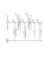
- FIG. 5 shows an operation example for UE 100 in RRC idle state or RRC inactive state to receive TRS.
- the TRS may be CSI-RS (Channel State Information-Reference Signal) used for tracking purposes. That is, in this embodiment, TRS resources may include CSI-RS resources.
- CSI-RS Channel State Information-Reference Signal
- the base station 200 transmits a specific system information block (hereinafter sometimes referred to as a specific SIB) including TRS resource settings. Specifically, the base station 200 transmits a system information block containing one or more TRS resource configuration parameters on a broadcast channel.
- the particular system information block may be an existing system information block other than system information block type 1 (SIB1) or a newly introduced type of system information block.
- UE 100 receives a specific system information block.
- the UE 100 configures the TRS resource set according to the TRS resource configuration included in a specific system information block. Specifically, the UE 100 configures a TRS resource set based on one or more TRS resource configuration parameter groups.
- the TRS resource setting for setting TRS for UE 100 in RRC idle state or RRC inactive state is CSI-ResourceConfig/NZP-CSI-RS-ResourceSet, bwp-ID, resourceType, trs-Info , repetition, powerControlOffset, powerControlOffsetSS, requencyDomainAllocation, firstOFDMSymbolInTimeDomain, Density, startingRB, nrofRBs, and subcarrierSpacing as parameters (3G PP TS38.331 reference).
- TRS resource configuration may be only part of the parameter group configured in UE 100 in the RRC connected state.
- step S22 the base station 200 transmits downlink control information (DCI) to the UE100.
- DCI downlink control information
- UE 100 receives DCI from base station 200 .
- the DCI includes an availability indicator that indicates whether TRS is transmitted based on the configured TRS resource set.
- the availability indicator may be referred to as a TRS availability indicator.
- the UE 100 determines whether TRS is transmitted based on the configured TRS resource set. UE100 performs the process of step S23, when it determines with TRS being transmitted. If the UE 100 determines that the TRS is not transmitted, the UE 100 does not have to perform the process of step S23. In this case, the UE 100 may perform processing for receiving the SSB.
- the base station 200 can flexibly control time/frequency synchronization based on the TRS by notifying the UE 100 via DCI whether or not to transmit the TRS.
- step S23 the base station 200 transmits TRS.
- UE 100 receives TRS using TRS resource configuration. By receiving the TRS, the UE 100 can achieve time/frequency synchronization without receiving the SSB.
- the UE 100 monitors and receives paging at the PO. Note that the UE 100 maintains the wake-up state from the reception of the TRS in step S21 to the PO. When the time from the TRS reception timing to the PO timing is short, the wakeup duration is short, and the power consumption of the UE 100 is reduced. In addition, the UE 100 can reduce power consumption accompanying reception of SSB by not receiving SSB.
- the availability indicator field containing the availability indicator is a variable-length field indicated by a maximum of 6 bits.
- the current 3GPP specifications do not define how the UE 100 determines the number of bits in the availability indicator field.
- the UE 100 may erroneously identify the availability indicator field and fail to correctly determine whether TRS is transmitted based on the configured TRS resource set. In one embodiment described later, an operation for making it possible to correctly determine whether TRS is transmitted based on the set TRS resource set will be described.
- the specific SIB includes a TRS resource set for general UEs performing DRX and a TRS resource set for eDRX UEs performing eDRX
- how the UE 100 determines the number of bits in the availability indicator field Unknown As a result, the UE 100 may erroneously identify the availability indicator field and fail to correctly determine whether TRS is transmitted based on the configured TRS resource set. In one embodiment described later, an operation for making it possible to correctly determine whether TRS is transmitted based on the set TRS resource set will be described.
- UE 100 includes communication unit 110 and control unit 120 .
- the communication unit 110 performs wireless communication with the base station 200 by transmitting and receiving wireless signals to and from the base station 200 .
- the communication unit 110 has at least one transmitter 111 and at least one receiver 112 .
- the transmitter 111 and receiver 112 may be configured to include multiple antennas and RF circuits.
- the antenna converts a signal into radio waves and radiates the radio waves into space. Also, the antenna receives radio waves in space and converts the radio waves into signals.
- the RF circuitry performs analog processing of signals transmitted and received through the antenna.
- the RF circuitry may include high frequency filters, amplifiers, modulators, low pass filters, and the like.
- the control unit 120 performs various controls in the UE 100.
- Control unit 120 controls communication with base station 200 via communication unit 110 .
- the operations of the UE 100 described above and below may be operations under the control of the control unit 120 .
- the control unit 120 may include at least one processor capable of executing a program and a memory that stores the program.
- the processor may execute a program to operate the control unit 120 .
- the control unit 120 may include a digital signal processor that performs digital processing of signals transmitted and received through the antenna and RF circuitry.
- the digital processing includes processing of the protocol stack of the RAN. Note that the memory stores programs executed by the processor, parameters related to the programs, and data related to the programs.
- the memory is ROM (Read Only Memory), EPROM (Erasable Programmable Read Only Memory), EEPROM (Electrically Erasable Programmable Read Only Memory), RAM (Random Access Mem ory) and flash memory. All or part of the memory may be included within the processor.
- the UE 100 configured in this way performs time/frequency synchronization in the downlink using TRS.
- the receiving unit 112 receives a specific SIB including the TRS resource setting, and a DCI including an availability indicator indicating whether TRS is transmitted based on the TRS resource set set by the TRS resource setting. Receive from base station 200 . Based on the availability indicator, the control unit 120 determines whether TRS is transmitted based on the configured TRS resource set. The control unit 120 determines the number of bits of the availability indicator field in which the availability indicator is stored based on the number of TRS resource set groups defined by the TRS resource configuration. This allows the UE 100 to identify the availability indicator field and correctly determine whether TRS is transmitted based on the configured TRS resource set.
- the configuration of the base station 200 according to the embodiment will be described with reference to FIG.
- the base station 200 has a communication section 210 , a network communication section 220 and a control section 230 .
- the communication unit 210 receives radio signals from the UE 100 and transmits radio signals to the UE 100.
- the communication unit 210 has at least one transmitter 211 and at least one receiver 212 .
- the transmitting section 211 and the receiving section 212 may be configured including an RF circuit.
- the RF circuitry performs analog processing of signals transmitted and received through the antenna.
- the RF circuitry may include high frequency filters, amplifiers, modulators, low pass filters, and the like.
- the network communication unit 220 transmits and receives signals to and from the network.
- the network communication unit 220 receives signals from adjacent base stations connected via an Xn interface, which is an interface between base stations, and transmits signals to the adjacent base stations. Also, the network communication unit 220 receives a signal from the core network device 300 connected via the NG interface, for example, and transmits the signal to the core network device 300 .
- the control unit 230 performs various controls in the base station 200.
- the control unit 230 controls communication with the UE 100 via the communication unit 210, for example.
- the control unit 230 controls communication with a node (for example, an adjacent base station, the core network device 300) via the network communication unit 220, for example.
- the operations of the base station 200 described above and below may be operations under the control of the control unit 230 .
- the control unit 230 may include at least one processor capable of executing programs and a memory storing the programs.
- the processor may execute a program to operate the controller 230 .
- Control unit 230 may include a digital signal processor that performs digital processing of signals transmitted and received through the antenna and RF circuitry.
- the digital processing includes processing of the protocol stack of the RAN.
- the memory stores programs executed by the processor, parameters related to the programs, and data related to the programs. All or part of the memory may be included within the processor.
- the base station 200 configured in this manner performs radio communication with the UE 100 that performs time/frequency synchronization in the downlink using TRS.
- the transmission unit 211 includes an SIB including TRS resource configuration, and a DCI including an availability indicator indicating whether TRS is transmitted based on the TRS resource set configured by the TRS resource configuration. , is transmitted to the UE 100 .
- the control unit 230 determines the number of bits of the availability indicator field in which the availability indicator is stored based on the number of TRS resource set groups defined by the TRS resource configuration. This allows the UE 100 to identify the availability indicator field and correctly determine whether TRS is transmitted based on the configured TRS resource set.
- the transmission unit 211 of the base station 200 transmits a specific SIB including TRS resource settings.
- Receiving section 112 of UE 100 receives the specific SIB.
- the specific SIB may include the configuration of TRS (eg, CSI-RS) for tracking that can be used by UE 100 in RRC idle state or RRC inactive state.
- TRS eg, CSI-RS
- a specific SIB may be referred to as SIBXX.
- a specific SIB includes TRS resource settings.
- the specific SIB includes, as TRS resource settings, a TRS resource set setting (trs-ResourceSetConfig-r17/TRS-ResourceSetConfig-r17) and an individual TRS setting list (nzp-CSI-RS-ResourceListForTracking-r17). and common TRS settings (nzp-CSI-RS-ResourceCommon-r17/NZP-CSI-RS-ResourceCommon-r17) (see E91 in FIG. 9).
- TRS resource set setting trs-ResourceSetConfig-r17/TRS-ResourceSetConfig-r17
- nzp-CSI-RS-ResourceListForTracking-r17 an individual TRS setting list
- common TRS settings nzp-CSI-RS-ResourceCommon-r17/NZP-CSI-RS-ResourceCommon-r17
- TRS-ResourceSetConfig-r17 may consist of one or more TRS resource set groups (TRS-ResourceSetGroup-r17) (see E92 in FIG. 9).
- the TRS resource set configuration may be configured in a list format containing TRS resource set groups.
- a TRS resource set configuration may define a TRS resource set group.
- a TRS resource set group may be a list of TRS resource sets (NZP-CSI-RS-ResourceSetSIB-r17) (see E93 in FIG. 9). Therefore, a TRS resource set group consists of grouped TRS resource sets. That is, the TRS resource set configuration may be a parameter for grouping TRS resource sets.
- a TRS resource set may be a set of a TRS resource set identifier (nzp-CSI-ResourceSetId-r17/NZP-CSI-RS-ResourceSetId) and a TRS resource (nzp-CSI-RS-Resources-r17).
- the TRS resource may be a list of TRS resource identifiers (NZP-CSI-RS-ResourceId) associated with the TRS resource.
- the individual TRS setting list is a list of individual TRS settings (NZP-CSI-RS-ResourceSIB-r17). As shown in FIG. 10, the individual TRS setting includes the identifier of the TRS resource (nzp-CSI-RS-ResourceId/NZP-CSI-RS-ResourceId), a parameter indicating the allocation of the TRS in the frequency direction (frequencyDomainAllocation), It may include a parameter (firstOFDMSymbolInTimeDomain) indicating TRS allocation in the time direction and a parameter (scramblingID/ScramblingId) indicating a scrambling identifier of TRS.
- a common TRS setting may be a set of parameters commonly applied to all individual TRS settings.
- the common TRS settings include a parameter (csi-FrequencyOccupation-r17/CSI-FrequencyOccupation) indicating the occupied range of the TRS in the frequency direction, and a parameter (powerControlOffsetSS-r17) indicating the power offset of the TRS with respect to the synchronization signal.
- a parameter indicating the periodicity and time offset of the TRS (periodicityAndOffset-r17/CSI-ResourcePeriodicityAndOffsetSIB-r17), and a parameter related to QCL of the TRS (qcl-InfoForTracking-r17).
- the control unit 120 of the UE 100 determines the number of bits in the availability indicator field. Specifically, the control unit 120 of the UE 100 determines the number of bits of the availability indicator field based on the number of TRS resource set groups. If the TRS resource set configuration is configured in a list format including TRS resource set groups, the control unit 120 of the UE 100 is based on the number of one or more TRS resource set group entries in the list format, availability indicator Determines the number of bits in the field. When the number of entries in the TRS resource set group (which may be the entry size) is N, the control unit 120 of the UE 100 determines that the number of bits of the availability indicator field is N.
- step S103 the transmission unit 211 of the base station 200 transmits DCI to the UE100.
- Receiving section 112 of UE 100 receives the DCI from base station 200 .
- the DCI may be DCI format 1_0 used for PDSCH scheduling in one downlink cell.
- DCI format 1_0 may include an availability indicator (TRS availability indication) (see E111 in FIG. 11).
- TRS availability indication may be stored in the availability indicator field within DCI format 1_0.
- the availability indicator may be sent by DCI format 1_0 CRC-scrambled with the Paging-Radio Network Temporary Identifier (P-RNTI).
- P-RNTI Paging-Radio Network Temporary Identifier
- the availability indicator is a bitmap of any number of bits from 1 to 6 when the TRS resource set configuration (TRS-ResourceSetConfig) is set. Therefore, the availability indicator field is indicated by any number of bits from 1 to 6. On the other hand, the availability indicator (ie, availability indicator field) is 0 bit if the TRS resource set configuration is not set.
- the bit positions of the bitmap that make up the availability indicator are associated with the TRS resource set group entries that are made up of the TRS resource set settings.
- the first or leftmost bit corresponds to the first entry in the TRS resource set group configured in the TRS resource set configuration
- the second bit corresponds to the TRS resource configured in the TRS resource set configuration.
- the number of bits in the availability indicator field corresponds to the number of TRS resource set groups configured by the TRS resource set configuration.
- the DCI may be DCI format 2_7 used to notify one or more UEs 100 of a paging early indicator and an availability indicator.
- DCI format 2_7 may include an availability indicator (see E112 in FIG. 11).
- the availability indicator may be stored in the availability indicator field within DCI format 2_7.
- the availability indicator may be sent by DCI format 2_7 CRC-scrambled with Paging Early Indicator-Radio Network Temporary Identifier (PEI-RNTI).
- PEI-RNTI Paging Early Indicator-Radio Network Temporary Identifier
- step S104 the control unit 120 of the UE 100 determines whether TRS is transmitted.
- the control unit 120 of the UE 100 identifies the availability indicator (or availability indicator field) based on the determined number of bits of the availability indicator. The control unit 120 determines whether or not the TRS is transmitted based on the specified availability indicator.
- the control unit 120 of the UE 100 if the value at the bit position of the bitmap that constitutes the availability indicator is a predetermined value (for example, "1"), the TRS of the TRS resource set group of the corresponding entry is Determine that it has been sent. On the other hand, when the value at the bit position is a value different from the predetermined value (for example, "0"), the control unit 120 determines that the TRS of the TRS resource set group of the corresponding entry has not been transmitted.
- a predetermined value for example, "1”
- Control unit 120 determines whether TRS is being transmitted based on the set TRS resource set based on the value of the bit position corresponding to the entry of the TRS resource set group to which the TRS resource set set in UE 100 belongs. judge. When determining that the TRS is transmitted based on the set TRS resource set, the control unit 120 executes the process of step S105. UE100 does not need to perform the process of step S105, when it determines with TRS not being transmitted. In this case, the UE 100 may perform processing for receiving the SSB.
- Steps S105 and S106 correspond to steps S23 and S24.
- the transmitting unit 211 of the base station 200 transmits the SIB including the TRS resource configuration and the availability indicator indicating whether or not the TRS is transmitted based on the TRS resource set configured by the TRS resource configuration. and the DCI containing are transmitted to the UE 100 .
- the control unit 230 of the base station 200 determines the number of bits of the availability indicator field in which the availability indicator is stored, based on the number of TRS resource set groups defined by the TRS resource configuration.
- the receiving unit 112 of the UE 100 transmits the SIB including the TRS resource configuration and the DCI including the availability indicator indicating whether or not the TRS is transmitted based on the TRS resource set configured by the TRS resource configuration to the base station 200.
- the control unit 120 determines whether TRS is transmitted based on the configured TRS resource set.
- the control unit 120 determines the number of bits of the availability indicator field in which the availability indicator is stored based on the number of TRS resource set groups defined by the TRS resource configuration. This allows the UE 100 to identify the availability indicator field and correctly determine whether TRS is transmitted based on the configured TRS resource set.
- the TRS resource settings may include TRS resource set settings configured by one or more TRS resource set groups.
- the control unit 120 may determine the number of bits of the availability indicator field based on the number of TRS resource set groups making up the TRS resource set configuration.
- the control unit 120 can determine the number of bits of the availability indicator field by setting the TRS resource set, and can correctly determine whether or not the TRS is transmitted based on the set TRS resource set.
- the TRS resource set configuration may be configured in a list format including one or more TRS resource set groups.
- the control unit 120 may determine the number of bits of the availability indicator field based on the number of entries of one or more TRS resource set groups in list format. As a result, even if the TRS resource set configuration does not include an identifier for identifying a group, the control unit 120 can determine the number of bits in the availability indicator field and reduce the amount of information in the TRS resource configuration.
- bit positions of the bitmap that constitutes the availability indicator may be associated with the entry.
- the control unit 120 may determine that the TRS of the TRS resource set group of the corresponding entry is transmitted. This allows the control unit 120 to determine whether TRS is being transmitted based on the TRS resource set included in the TRS resource set group of the corresponding entry. As a result, it is possible to prevent the UE 100 from trying to receive the TRS even though the TRS has not been transmitted.
- the UE 100 determines the number of bits of the availability indicator field based on the group identifier.
- the transmission unit 211 of the base station 200 transmits the following specific SIB.
- Receiving section 112 of UE 100 receives the specific SIB.
- the TRS resource set configuration (trs-ResourceSetConfig-r17) included in the specific SIB may be a list of TRS resource sets (NZP-CSI-RS-ResourceSetSIB-r17) (E121 in FIG. 12 reference).
- the TRS resource set identifies a TRS resource set identifier (nzp-CSI-ResourceSetId-r17/NZP-CSI-RS-ResourceSetId), a TRS resource (nzp-CSI-RS-Resources-r17), and a TRS resource set group. and a group identifier (trs-ResourceSetGroupId-r17) (see E122 in FIG. 12).
- each TRS resource set group is composed of TRS resource sets having the same corresponding group identifier value.
- the base station 200 (network 10) configures a TRS resource set group with consecutive IDs starting from 0.
- the control unit 120 of the UE 100 determines the number of bits of the availability indicator field based on the number of group identifiers. When the number of group identifiers is N, the control unit 120 determines that the number of bits of the availability indicator field is N.
- each code point of the "availability indicator" in the DCI field ie the bit position of the bitmap of the availability indicator, is associated with the TRS resource set group ID.
- the first or leftmost bit of the bitmap that constitutes the availability indicator corresponds to TRS resource set group ID 0, and the second bit corresponds to TRS resource set group ID 1 (E131 in FIG. 13). and E132).
- step S104 the control unit 120 of the UE 100 is based on the set TRS resource set based on the value of the bit position corresponding to the group identifier that identifies the TRS resource set group to which the TRS resource set set in the UE 100 belongs. Determine whether a TRS has been sent.
- the TRS resource setting may include a TRS resource set setting made up of one or more TRS resource sets associated with a group identifier.
- the control unit 120 may determine the number of bits of the availability indicator field based on the number of group identifiers. This allows the UE 100 to identify the availability indicator field and correctly determine whether TRS is transmitted based on the configured TRS resource set.
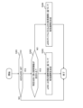
- a third operation example will be described with reference to FIGS. 8 and 14 . Descriptions similar to those of the above operation example are omitted as appropriate.
- one or more TRS resource set groups and group identifiers are associated in a format different from that of the second operation example.
- the specific SIB includes TRS resource settings, as in the first operation example.
- TRS resource set configuration trs-ResourceSetConfig-r17/TRS-ResourceSetConfig-r17
- TRS-ResourceSetGroup-r17 one or more TRS resource set groups
- trs-ResourceSetGroupId-r17 group identifier
- the TRS resource settings include TRS resource set settings associated with one or more TRS resource set groups and group identifiers.
- step S102 the control unit 120 of the UE 100 determines the number of bits of the availability indicator field based on the number of group identifiers, as in the second operation example. This allows the UE 100 to identify the availability indicator field and correctly determine whether TRS is transmitted based on the configured TRS resource set.
- the TRS resource configuration includes separate TRS resource set groups for normal UEs and eDRX UEs performing DRX.
- step S201 the transmission unit 211 of the base station 200 transmits the following specific SIB.
- the specific SIB includes a first TRS resource set group for general UEs performing DRX and a second TRS resource set group for eDRX UEs performing eDRX.
- different group identifiers are assigned to the first TRS resource set group and the second TRS resource set group.
- the first TRS resource set group includes a TRS resource set group configured by a TRS resource set associated with group identifier #0 and a TRS associated with group identifier #1. and a TRS resource set group composed of resource sets.
- the second TRS resource set includes a TRS resource set group made up of TRS resource sets associated with group identifier #2.
- Each TRS resource set associated with group identifier #0 and group identifier #1 is a normal TRS resource set for UEs.
- Each TRS resource set associated with group identifier #2 is a TRS resource set for eDRX UEs.
- a specific SIB may contain a group identifier and information indicating whether the TRS resource set associated with the group identifier is for eDRX UEs (or for normal UEs).
- each TRS resource set may be associated with information indicating whether the TRS resource set is for eDRX UEs (or for normal UEs).
- the group identifier may be associated with information indicating whether the TRS resource set associated with the group identifier is for eDRX UEs (or for normal UEs). Based on this information, the control unit 120 of the UE 100 can determine whether each TRS resource set is for normal UEs or for eDRX UEs.
- the specific SIB may contain duration information indicating the validity duration of the availability indicator indicated in the availability indicator field for each of the first TRS resource set and the second TRS resource set.
- the period information includes first period information that is the validity period of the availability indicator for the first TRS resource set and second period information that is the validity period of the availability indicator for the second TRS resource set; may contain
- the control unit 120 can determine the validity period of the availability indicator for the first TRS resource set based on the first duration information. Similarly, the control unit 120 can determine the validity period of the availability indicator for the second TRS resource set based on the second period information.
- the validity period for the first TRS resource set may be an integer multiple of the first time unit.
- the first time unit may be, for example, one default paging cycle.
- the validity period for the second TRS resource set may be an integer multiple of a second time unit longer than the first time unit.
- the first time unit may be, for example, an eDRX cycle, or an acquisition period (specifically, an eDRX acquisition period) that triggers the UE 100 in which eDRX is configured to acquire an updated SIB. good too.
- the control unit 120 of the UE 100 determines the number of bits in the availability indicator field.
- the control unit 120 determines the number of bits of the availability indicator field based on the total number of the first TRS resource set group and the second TRS resource set group.
- control unit 120 may determine the number of bits of the availability indicator field based on the total number of group identifiers of the first TRS resource set group and the second TRS resource set group. In the example of FIG. 16, the control unit 120 controls the total number of 2, which is the number of group identifiers of the first TRS resource set group, and 1, which is the number of group identifiers of the second TRS resource set group (that is, total value) of 3 may be determined as the number of bits in the availability indicator field.
- Steps S203 to S206 are the same as steps S103 to S106.
- the control unit 120 when the first TRS resource set associated with the group identifier #0 is set, the control unit 120, based on the value of the first bit position of the bitmap constituting the availability indicator, the TRS is transmitted. Similarly, the control unit 120, for example, when the second TRS resource set associated with the group identifier # 2 is set, based on the value of the third bit position of the bitmap constituting the availability indicator , TRS is transmitted.
- the control unit 120 receives TRS based on the first TRS resource set. If the UE 100 is an eDRX UE, the control unit 120 receives TRS based on the second TRS resource set. For example, when the DRX setting is set (for example, the DRX cycle is applied), the control unit 120 determines that the UE 100 is a normal UE. On the other hand, the control unit 120 determines that the UE 100 is an eDRX UE, for example, when the eDRX setting is set (for example, the eDRX cycle is applied).
- the control unit 120 may determine the number of bits of the availability indicator field based on the total number of the first TRS resource set group and the second TRS resource set group. Also, the control unit 120 may determine the number of bits of the availability indicator field based on the total number of group identifiers of the first TRS resource set group and the second TRS resource set group.
- the specific SIB includes a TRS resource set for general UEs performing DRX and a TRS resource set for eDRX UEs performing eDRX
- the UE 100 can specify the availability indicator field, It can correctly determine whether TRS is transmitted based on the configured TRS resource set.
- the base station 200 transmits based on the first TRS resource set. For each TRS and TRS transmitted based on the second set of TRS resources, it can be determined whether to transmit or not. This allows the base station 200 to flexibly control TRS transmission.
- the receiving unit 112 receives from the base station 200 a specific SIB including period information indicating the valid period of the availability indicator for each of the first TRS resource set and the second TRS resource set.
- the control unit 120 controls the It is possible to know the validity period of the availability indicator for each.
- the UE 100 can correctly determine whether TRS is transmitted based on the set TRS resource set.
- a fifth operation example will be described with reference to FIG. Descriptions similar to those of the above operation example are omitted as appropriate.
- the UE 100 determines the number of bits in the availability indicator field based on the total number of groups having the largest number of the first TRS resource set group and the second TRS resource set group.
- group identifiers are individually assigned to the first TRS resource set group and the second TRS resource set group.
- the first TRS resource set group includes a TRS resource set group configured by a TRS resource set associated with group identifier #0, and a TRS resource set associated with group identifier #1. and a TRS resource set group composed of resource sets.
- the second TRS resource set includes a TRS resource set group made up of TRS resource sets associated with group identifier #0.
- Each TRS resource set associated with group identifier #0 and group identifier #1 is a normal TRS resource set for UEs.
- Each TRS resource set associated with group identifier #0 is a TRS resource set for eDRX UEs.
- the control unit 120 of the UE 100 may determine the number of bits of the availability indicator field based on the total number of groups having the largest number of the first TRS resource set group and the second TRS resource set group.
- the control unit 120 may determine the number of bits of the availability indicator field based on the total number of group identifiers of the large number of groups.
- the control unit 120 compares 2, which is the number of group identifiers of the first TRS resource set group, with 1, which is the number of group identifiers of the second TRS resource set group, and It is determined that the number of group identifiers in one TRS resource set group is large.
- the control unit 120 may determine 2, which is the number of group identifiers of the first TRS resource set group having the largest number, as the number of bits of the availability indicator field.
- the control unit 120 may determine the number of bits of the availability indicator field based on the total number of groups having the largest number of the first TRS resource set group and the second TRS resource set group. . Also, the control unit 120 may determine the number of bits of the availability indicator field based on the total number of group identifiers with a large number. As a result, even when the specific SIB includes a TRS resource set for general UEs performing DRX and a TRS resource set for eDRX UEs performing eDRX, the UE 100 can specify the availability indicator field, It can correctly determine whether TRS is transmitted based on the configured TRS resource set.
- base station 200 determines the number of TRS resource set groups to which group identifiers are assigned. can be increased compared to the fourth operation example. This allows the base station 200 to finely configure the TRS resource settings.
- the control unit 230 of the base station 200 assigns the same group identifier (for example, group identifier #0 in FIG. 16) to the first TRS resource set group and the second TRS resource set group. If so, for TRSs transmitted based on the first TRS resource set and the second TRS resource set assigned the same group identifier, determine whether to transmit both TRSs or not to transmit both TRSs. do. That is, the control unit 230 of the base station 200 does not perform control of transmitting TRS based on one TRS resource set and not transmitting TRS based on the other TRS resource set.
- group identifier for example, group identifier #0 in FIG. 16
- the control unit 120 of the UE 100 may perform the following processing based on the reception of the specific SIB, for example.
- step S301 the control unit 120 of the UE 100 determines whether the UE 100 is an eDRX UE. If the UE 100 is an eDRX UE, the control unit 120 executes the process of step S302. On the other hand, if the UE 100 is not an eDRX UE, the control unit 120 may end the process.
- control unit 120 may determine that the UE 100 is an eDRX UE, for example, when the eDRX setting is set (for example, the eDRX cycle is applied). The control unit 120 may determine that the UE 100 is not an eDRX UE when DRX settings are configured (for example, a DRX cycle is applied).
- step S302 the control unit 120 determines whether or not the specific SIB includes second period information indicating the validity period of the availability indicator for the second TRS resource set. If the specific SIB includes the second period information, control unit 120 executes the process of step S303. If the specific SIB does not contain the second period information, control unit 120 executes the process of step S304.
- step S303 the control unit 120 determines the validity period based on the second period information.
- control unit 120 may determine the validity period based on the eDRX cycle or the eDRX acquisition cycle that triggers the eDRX UE to acquire the updated SIB.
- the control unit 120 may, for example, consider the period until the next eDRX cycle as the valid period as a default setting. Alternatively, the control unit 120 may, for example, regard the interval up to the boundary of the acquisition cycle as the effective period as a default setting.
- the control unit 120 determines the validity period based on the second period information. You can If the specific SIB does not include the second period information, the control unit 120 may determine the valid period based on the eDRX cycle or the eDRX acquisition period. Thereby, the UE 100 can appropriately determine the valid period regardless of the presence or absence of the second period information in the specific SIB. As a result, the control unit 120 can correctly determine whether the TRS is transmitted based on the set TRS resource set.
- the operation sequences (and operation flows) in the above-described embodiments do not necessarily have to be executed in chronological order according to the order described in the flow diagrams or sequence diagrams. For example, the steps in the operations may be performed out of order or in parallel with the order illustrated in the flow diagrams or sequence diagrams. Also, some steps in the operation may be omitted and additional steps may be added to the process. Further, the operation sequences (and operation flows) in the above-described embodiments may be implemented independently, or two or more operation sequences (and operation flows) may be combined and implemented. For example, some steps of one operation flow may be added to another operation flow, or some steps of one operation flow may be replaced with some steps of another operation flow.
- the mobile communication system 1 based on NR has been described as an example.
- the mobile communication system 1 is not limited to this example.
- the mobile communication system 1 may be a TS-compliant system of either LTE (Long Term Evolution) or another generation system (for example, 6th generation) of the 3GPP standards.
- Base station 200 may be an eNB that provides E-UTRA user plane and control plane protocol termination towards UE 100 in LTE.
- the mobile communication system 1 may be a system conforming to a TS of a standard other than the 3GPP standard.
- the base station 200 may be an IAB (Integrated Access and Backhaul) donor or an IAB node.
- IAB Integrated Access and Backhaul
- a program that causes a computer to execute each process performed by the UE 100 or the base station 200 may be provided.
- the program may be recorded on a computer readable medium.
- a computer readable medium allows the installation of the program on the computer.
- the computer-readable medium on which the program is recorded may be a non-transitory recording medium.
- the non-transitory recording medium is not particularly limited, but may be, for example, a recording medium such as CD-ROM (Compact Disk Read Only Memory) or DVD-ROM (Digital Versatile Disc Read Only Memory). good.
- circuits that execute each process performed by the UE 100 or the base station 200 may be integrated, and at least a part of the UE 100 or the base station 200 may be configured as a semiconductor integrated circuit (chipset, SoC (System On Chip)).
- “transmit” may mean performing at least one layer of processing in the protocol stack used for transmission, or physically transmitting the signal wirelessly or by wire. It may mean sending to Alternatively, “transmitting” may mean a combination of performing the at least one layer of processing and physically transmitting the signal wirelessly or by wire.
- “receive” may mean performing processing of at least one layer in the protocol stack used for reception, or physically receiving a signal wirelessly or by wire. may mean that Alternatively, “receiving” may mean a combination of performing the at least one layer of processing and physically receiving the signal wirelessly or by wire.
- “obtain/acquire” may mean obtaining information among stored information, and may mean obtaining information among information received from other nodes.
- references to "based on” and “depending on/in response to” are used unless otherwise specified. does not mean The phrase “based on” means both “based only on” and “based at least in part on.” Similarly, the phrase “depending on” means both “only depending on” and “at least partially depending on.” Similarly, “include” and “comprise” are not meant to include only the recited items, and may include only the recited items or in addition to the recited items. Means that it may contain further items. Similarly, in the present disclosure, “or” does not mean exclusive OR, but means logical OR. Furthermore, any references to elements using the "first,” “second,” etc.
- a receiver that receives a system information block (SIB) from a base station; a control unit that determines the number of bits in a bitmap of a tracking reference signal (TRS) availability indicator in downlink control information (DCI); The control unit If the SIB contains a TRS resource set configuration that is a list of TRS resource sets, determine the number of bits based on an identifier associated with the TRS resource set; A communications device that determines the number of bits to be 0 if the TRS resource set configuration is not included in the SIB.
- SIB system information block
- TRS tracking reference signal
- the receiving unit receives the DCI from the base station, 5.
- the communication device according to any one of appendices 1 to 4, wherein the control unit identifies the availability indicator of the received DCI based on the determined number of bits.
- SIB system information block
- TRS tracking reference signal
- a communication method performed by a communication device comprising: receiving a system information block (SIB) from a base station; determining the number of bits in a bitmap of a tracking reference signal (TRS) availability indicator in downlink control information (DCI); In the determining step, If the SIB contains a TRS resource set configuration that is a list of TRS resource sets, determine the number of bits based on an identifier associated with the TRS resource set; determining that the number of bits is 0 if the TRS resource set configuration is not included in the SIB.
- SIB system information block
- TRS tracking reference signal
Landscapes
- Engineering & Computer Science (AREA)
- Computer Networks & Wireless Communication (AREA)
- Signal Processing (AREA)
- Mobile Radio Communication Systems (AREA)
Abstract
L'invention concerne un dispositif de communication (100) qui comprend : une unité de réception qui reçoit un bloc d'informations de système (SIB) en provenance d'une station de base (200) ; et une unité de commande (120) qui détermine le nombre de bits dans un tableau de bits d'indicateur de disponibilité d'un signal de référence de suivi (TRS) dans des informations de contrôle de liaison descendante (DCI). Si une configuration d'ensemble de ressources TRS, qui est une liste d'ensembles de ressources TRS, est incluse dans le SIB, l'unité de commande (120) détermine le nombre de bits sur la base d'un identifiant correspondant à l'ensemble de ressources TRS. Si la configuration d'ensemble de ressources TRS n'est pas incluse dans le SIB, l'unité de commande (120) détermine le nombre de bits comme étant égal à zéro.
Applications Claiming Priority (2)
| Application Number | Priority Date | Filing Date | Title |
|---|---|---|---|
| JP2022001588 | 2022-01-07 | ||
| JP2022-001588 | 2022-01-07 |
Publications (1)
| Publication Number | Publication Date |
|---|---|
| WO2023132271A1 true WO2023132271A1 (fr) | 2023-07-13 |
Family
ID=87073610
Family Applications (1)
| Application Number | Title | Priority Date | Filing Date |
|---|---|---|---|
| PCT/JP2022/047578 WO2023132271A1 (fr) | 2022-01-07 | 2022-12-23 | Dispositif de communication, station de base et procédé de communication |
Country Status (1)
| Country | Link |
|---|---|
| WO (1) | WO2023132271A1 (fr) |
Citations (1)
| Publication number | Priority date | Publication date | Assignee | Title |
|---|---|---|---|---|
| WO2021199415A1 (fr) * | 2020-04-02 | 2021-10-07 | 株式会社Nttドコモ | Terminal et procédé de communication |
-
2022
- 2022-12-23 WO PCT/JP2022/047578 patent/WO2023132271A1/fr unknown
Patent Citations (1)
| Publication number | Priority date | Publication date | Assignee | Title |
|---|---|---|---|---|
| WO2021199415A1 (fr) * | 2020-04-02 | 2021-10-07 | 株式会社Nttドコモ | Terminal et procédé de communication |
Non-Patent Citations (1)
| Title |
|---|
| MODERATOR (SAMSUNG): "Moderator summary for multi-beam enhancement", 3GPP TSG RAN WG1 #107-E, R1-2112683, 11 November 2021 (2021-11-11), XP052075755 * |
Similar Documents
| Publication | Publication Date | Title |
|---|---|---|
| EP3949542A1 (fr) | Procédés de configuration de signal de réveil (wus) basée sur un canal de commande physique de liaison descendante (pdcch) | |
| CN114175558B (zh) | 用户装备、基站和方法 | |
| CN114450915A (zh) | 用户装备、基站和方法 | |
| EP4102916A1 (fr) | Procédé de déclenchement de phr prenant en charge une partie dormante de bande passante dans un système de communication mobile de prochaine génération, et procédé et dispositif de configuration de phr | |
| CN114175562B (zh) | 用户装备、基站装置和方法 | |
| WO2023132271A1 (fr) | Dispositif de communication, station de base et procédé de communication | |
| US20230023825A1 (en) | Terminal apparatus, base station apparatus, and communication method | |
| WO2023120434A1 (fr) | Station de base et procédé de communication | |
| WO2023153312A1 (fr) | Dispositif de communication et procédé de communication | |
| WO2021066199A1 (fr) | Appareil terminal, appareil de station de base, et procédé de communication | |
| WO2023008483A1 (fr) | Dispositif de communication, station de base et procédé de communication | |
| WO2023022188A1 (fr) | Dispositif de communication, station de base et procédé de communication | |
| WO2023008481A1 (fr) | Dispositif de communication, station de base et procédé de communication | |
| US20240188037A1 (en) | Communication apparatus, base station, and communication method | |
| WO2023080036A1 (fr) | Dispositif de communication, station de base, et procédé de communication | |
| WO2023080037A1 (fr) | Dispositif de communication, station de base, et procédé de communication | |
| WO2023080035A1 (fr) | Dispositif de communication, station de base et procédé de communication | |
| WO2023068350A1 (fr) | Dispositif de communication, station de base et procédé de communication | |
| WO2023080038A1 (fr) | Dispositif de communication, station de base et procédé de communication | |
| WO2023063262A1 (fr) | Dispositif de communication, station de base et procédé de communication | |
| EP4336930A1 (fr) | Dispositif de communication, station de base et procédé de communication | |
| US20240073924A1 (en) | Communication apparatus, base station, and method | |
| US20240080170A1 (en) | Communication apparatus, base station, and communication method | |
| EP4336932A1 (fr) | Équipement utilisateur, station de base et procédé de commande de communication | |
| WO2023238686A1 (fr) | Dispositif de communication, station de base et procédé de communication |
Legal Events
| Date | Code | Title | Description |
|---|---|---|---|
| 121 | Ep: the epo has been informed by wipo that ep was designated in this application |
Ref document number: 22918855 Country of ref document: EP Kind code of ref document: A1 |