WO2023127750A1 - 力覚提示装置 - Google Patents
力覚提示装置 Download PDFInfo
- Publication number
- WO2023127750A1 WO2023127750A1 PCT/JP2022/047735 JP2022047735W WO2023127750A1 WO 2023127750 A1 WO2023127750 A1 WO 2023127750A1 JP 2022047735 W JP2022047735 W JP 2022047735W WO 2023127750 A1 WO2023127750 A1 WO 2023127750A1
- Authority
- WO
- WIPO (PCT)
- Prior art keywords
- vibrating body
- vibrating
- virtual plane
- control mode
- virtual
- Prior art date
- Legal status (The legal status is an assumption and is not a legal conclusion. Google has not performed a legal analysis and makes no representation as to the accuracy of the status listed.)
- Ceased
Links
Images


Classifications
-
- B—PERFORMING OPERATIONS; TRANSPORTING
- B06—GENERATING OR TRANSMITTING MECHANICAL VIBRATIONS IN GENERAL
- B06B—METHODS OR APPARATUS FOR GENERATING OR TRANSMITTING MECHANICAL VIBRATIONS OF INFRASONIC, SONIC, OR ULTRASONIC FREQUENCY, e.g. FOR PERFORMING MECHANICAL WORK IN GENERAL
- B06B1/00—Methods or apparatus for generating mechanical vibrations of infrasonic, sonic, or ultrasonic frequency
- B06B1/02—Methods or apparatus for generating mechanical vibrations of infrasonic, sonic, or ultrasonic frequency making use of electrical energy
- B06B1/04—Methods or apparatus for generating mechanical vibrations of infrasonic, sonic, or ultrasonic frequency making use of electrical energy operating with electromagnetism
-
- G—PHYSICS
- G06—COMPUTING OR CALCULATING; COUNTING
- G06F—ELECTRIC DIGITAL DATA PROCESSING
- G06F3/00—Input arrangements for transferring data to be processed into a form capable of being handled by the computer; Output arrangements for transferring data from processing unit to output unit, e.g. interface arrangements
- G06F3/01—Input arrangements or combined input and output arrangements for interaction between user and computer
Definitions
- the present invention relates to a haptic presentation device.
- the force sense presentation device described in Patent Document 1 includes a housing, a vibrator, and a control device.
- the vibrator is located inside the housing.
- the housing is used, for example, by being held in the user's hand.
- the control device presents a force sense in a specific direction by controlling the vibration pattern of the vibrator. As a result, the user gripping the housing feels a sense of force as if the force sense device were moving in a specific direction.
- the haptic presentation device of Patent Document 1 presents a haptic sensation as if the haptic presentation device is rotating, and variously changes the virtual rotation axis of the haptic sensation generated by the haptic presentation device. You can't do it.
- the present invention provides a housing that can be gripped by a user's hand, three or more vibrating bodies positioned inside the housing, and a vibration pattern of each of the vibrating bodies. and a control device capable of presenting a force sensation from each of the vibrating bodies by controlling the arrangement of the plurality of vibrating bodies so that three or more of the vibrating bodies are not positioned on the same imaginary straight line.
- a specific one of the plurality of vibrating bodies is defined as a first vibrating body, the direction of the force sense presented by the first vibrating body is defined as a first direction, and one of the plurality of vibrating bodies is A specific one different from the first vibrating body is defined as a second vibrating body, the direction of force sensation presented by the second vibrating body is defined as a second direction, and the first vibrating body among the plurality of vibrating bodies and a specific one different from the second vibrating body is defined as a third vibrating body, the direction of the force sense presented by the third vibrating body is defined as a third direction, the first vibrating body, the second vibrating body, and the virtual plane passing through the third vibrating body is defined as a virtual plane, the control device is configured such that the first direction and the second direction intersect the virtual plane, and the first direction is A direction opposite to the second direction across the virtual plane, and the third direction is on the same side of the virtual plane as the first direction or a direction parallel to the virtual plane so that the first control mode for controlling the vibration pattern
- the control device can execute each vibrator in the first control mode and the second control mode.
- the force sense presentation device presents the user with a force sense of rotation.
- the haptic presentation device can change the virtual rotation axis of the haptic presentation device to a different axis.
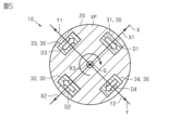
- the haptic device 10 includes a housing 20, four vibrating bodies 30, and a control device 40. As shown in FIG. The housing 20 is spherical as a whole. The diameter of the housing 20 is about 5 cm or more and 30 cm or less. That is, the housing 20 has a size that allows the user to grasp it by hand.
- the four vibrating bodies 30 are positioned inside the housing 20 . Although details are omitted, the four vibrating bodies 30 are fixed inside the housing 20 . As shown in FIG. 2, a virtual plane passing through at least three vibrating bodies 30 is assumed to be a virtual plane VP. In this embodiment, the virtual plane VP passes through four vibrating bodies 30, that is, all vibrating bodies 30. FIG. The virtual plane VP passes through the center of gravity G of the housing 20 .
- the center of gravity G of the housing 20 coincides with the geometric center of the housing 20 when the housing 20 is viewed in a direction orthogonal to the virtual plane VP. That is, the center of gravity G is the center of the spherical casing 20 .
- a first reference axis X is defined as an axis passing through the center of gravity G of the housing 20 and parallel to the virtual plane VP.
- a second reference axis Y is defined as an axis perpendicular to the first reference axis X and parallel to the virtual plane VP. Therefore, the virtual plane VP is a plane containing the first reference axis X and the second reference axis Y.
- the third reference axis Z is an axis that passes through the center of gravity G of the housing 20 and is perpendicular to the virtual plane VP.
- one of the directions along the first reference axis X is defined as a first positive direction X1
- the direction opposite to the first positive direction X1 is defined as a first negative direction X2.
- One of the directions along the second reference axis Y is defined as a second positive direction Y1, and the direction opposite to the second positive direction Y1 is defined as a second negative direction Y2.
- one of the directions along the third reference axis Z is defined as a third positive direction Z1, and the direction opposite to the third positive direction Z1 is defined as a third negative direction Z2.
- the vibrating body 30 has a substantially cubic shape.
- the vibrating body 30 is configured to vibrate in directions along two reference axes.
- the vibrating body 30 includes two voice coil motors, weights corresponding to the respective voice coil motors, and a cubic case that houses them.
- the weight vibrates due to the force generated as the current flows through the coil of the voice coil motor.
- the case vibrates due to the vibration of the weight.
- the four vibrating bodies 30 are a first vibrating body 31, a second vibrating body 32, a third vibrating body 33, and a fourth vibrating body .
- the first vibrating body 31 is positioned on the first reference axis X.
- the first vibrating body 31 is positioned on the first positive direction X1 side with respect to the center of gravity G.
- the first reference axis X is a virtual straight line passing through the first vibrating body 31 and the second vibrating body 32 .
- the second vibrating body 32 is positioned on the first reference axis X. Also, the second vibrating body 32 is located on the first negative direction X2 side with respect to the center of gravity G. As shown in FIG. The distance from the second vibrating body 32 to the center of gravity G is equal to the distance from the first vibrating body 31 to the center of gravity G. There are two directions of vibration of the second vibrating body 32: a direction along the second reference axis Y and a direction along the third reference axis Z. As shown in FIG.
- the third vibrating body 33 is positioned on the second reference axis Y. Also, the third vibrating body 33 is located on the second positive direction Y1 side with respect to the center of gravity G. As shown in FIG. The distance from the third vibrating body 33 to the center of gravity G is equal to the distance from the first vibrating body 31 to the center of gravity G. There are two directions of vibration of the third vibrating body 33, namely, a direction along the first reference axis X and a direction along the third reference axis Z. As shown in FIG.
- the fourth vibrating body 34 is positioned on the second reference axis Y. Also, the fourth vibrating body 34 is positioned on the second negative direction Y2 side with respect to the center of gravity G. As shown in FIG. The distance from the fourth vibrating body 34 to the center of gravity G is equal to the distance from the first vibrating body 31 to the center of gravity G. There are two directions of vibration of the fourth vibrating body 34, namely, a direction along the first reference axis X and a direction along the third reference axis Z. As shown in FIG.
- the third vibrating body 33 and the fourth vibrating body 34 are positioned on the second reference axis Y, while the first vibrating body 31 and the second vibrating body 32 pass along the first reference axis X. not located.
- the arrangement of the plurality of vibrating bodies 30 is such that three or more vibrating bodies 30 are not positioned on the same imaginary straight line.
- each vibrating body 30 is positioned on either the first reference axis X or the second reference axis Y. As shown in FIG. That is, the four vibrating bodies 30 are positioned on the virtual plane VP.
- the control device 40 is located inside the housing 20 . 2 to 5, illustration of the control device 40 is omitted.
- the control device 40 includes a CPU and a ROM, and executes software processing.
- the control device 40 is connected to each vibrator 30 by a signal line. By controlling the vibration pattern of each vibrating body 30, it is possible to present a force sensation in a specific direction from each vibrating body 30.
- FIG. Although illustration is omitted, the force sense presentation device 10 includes a battery.
- the battery is located inside the housing 20 .
- the battery is connected to the control device 40 and each vibrator 30 by power lines. The battery supplies power to the control device 40 and each vibrator 30 .
- control mode The control device 40 can execute three control modes. Thereby, the user who grips the housing 20 can feel three kinds of force sensations. All of the three kinds of haptic sensations are haptic sensations that cause the housing 20 to rotate, but the virtual rotation axis of the housing 20 is different. In each control mode, the combinations of the directions of the force sensation presented by the plurality of vibrating bodies 30 are different from each other. Further, in each control mode, the magnitudes of the force sensations presented by the plurality of vibrating bodies 30 are all the same.
- the three control modes are a first control mode, a second control mode and a third control mode.
- the direction of the force sense presented by the first vibrating body 31 be the first direction D1.
- the direction of the force sense presented by the second vibrating body 32 is defined as a second direction D2.
- the direction of the force sense presented by the third vibrating body 33 is defined as a third direction D3.
- the direction of force sense presented by the fourth vibrating body 34 is defined as a fourth direction D4.
- the control device 40 changes the vibration pattern of the first vibrating body 31 so that the first direction D1 is the third negative direction Z2, i.e., the depth direction in FIG. Control.
- the control device 40 controls the vibration pattern of the second vibrating body 32 so that the second direction D2 is the third positive direction Z1, that is, the front side of the drawing in FIG.
- the control device 40 controls the vibration pattern of the third vibrating body 33 so that the third direction D3 is the third negative direction Z2.
- the control device 40 controls the vibration pattern of the fourth vibrating body 34 so that the fourth direction D4 is the third positive direction Z1.
- the first direction D1 intersects the virtual plane VP.
- the second direction D2 intersects the virtual plane VP.
- the third direction D3 intersects the virtual plane VP.
- the fourth direction D4 intersects the virtual plane VP.
- the first direction D1 is opposite to the second direction D2. Therefore, the first direction D1 is the direction opposite to the second direction D2 across the virtual plane VP.
- the third direction D3 is the same direction as the first direction D1. Therefore, the third direction D3 is on the same side as the first direction D1 across the virtual plane VP. Further, the fourth direction D4 is the same direction as the second direction D2. Therefore, the fourth direction D4 is on the same side as the second direction D2 across the virtual plane VP.
- the control device 40 controls the vibration pattern of the first vibrating body 31 so that the first direction D1 is the third positive direction Z1.
- the control device 40 controls the vibration pattern of the second vibrating body 32 so that the second direction D2 is the third negative direction Z2.
- the control device 40 controls the vibration pattern of the third vibrating body 33 so that the third direction D3 is the third negative direction Z2.
- the control device 40 controls the vibration pattern of the fourth vibrating body 34 so that the fourth direction D4 is the third positive direction Z1.
- the first direction D1 intersects the virtual plane VP.
- the second direction D2 intersects the virtual plane VP.
- the third direction D3 intersects the virtual plane VP.
- the fourth direction D4 intersects the virtual plane VP.
- the first direction D1 is opposite to the third direction D3. Therefore, the first direction D1 is the direction opposite to the third direction D3 across the virtual plane VP.
- the second direction D2 is the same direction as the third direction D3. Therefore, the second direction D2 is on the same side as the third direction D3 across the virtual plane VP.
- the fourth direction D4 is the same direction as the first direction D1. Therefore, the fourth direction D4 is on the same side as the first direction D1 across the virtual plane VP.
- the control device 40 controls the third direction D3 and the fourth direction D4 in the same manner as in the first control mode.
- the control device 40 controls the vibration pattern of the first vibrating body 31 so that the first direction D1 is the second negative direction Y2.
- the control device 40 controls the vibration pattern of the second vibrating body 32 so that the second direction D2 is the second positive direction Y1.
- the control device 40 controls the vibration pattern of the third vibrating body 33 so that the third direction D3 is the first positive direction X1.
- the control device 40 controls the vibration pattern of the fourth vibrating body 34 so that the fourth direction D4 is the first negative direction X2.
- the first direction D1 to the fourth direction D4 are parallel to the virtual plane VP.
- the first direction D1 and the second direction D2 are directions orthogonal to the first reference axis X.
- the first direction D1 is opposite to the second direction D2. Therefore, the first direction D1 is the direction opposite to the second direction D2 with the first reference axis X passing through the first vibrating body 31 and the second vibrating body 32 interposed therebetween.
- the third direction D3 and the fourth direction D4 are directions perpendicular to the second reference axis Y in the third control mode. Furthermore, the third direction D3 is opposite to the fourth direction D4. Therefore, the third direction D3 is the direction opposite to the fourth direction D4 with the second reference axis Y passing through the third vibrating body 33 and the fourth vibrating body 34 interposed therebetween.
- the control device 40 controls each vibrator 30 in each of the control modes described above while the user holds the housing 20 of the force sense presentation device 10 by hand. A user's hand is given a haptic sensation from each vibrator 30 from the housing 20 .
- the first direction D1 and the third direction D3 are the third negative direction Z2.
- the second direction D2 and the fourth direction D4 are the third positive direction Z1.
- the first virtual axis R1 passes through the center of gravity G and extends on the virtual plane VP.
- a first virtual axis R1 passes between the first vibrating body 31 and the fourth vibrating body 34 .
- the first virtual axis R ⁇ b>1 passes between the second vibrating body 32 and the third vibrating body 33 .
- the acute angle formed by the first virtual axis R1 and the first reference axis X is 45 degrees.
- the acute angle formed by the first virtual axis R1 and the second reference axis Y is 45 degrees.
- the first direction D1 and the fourth direction D4 are the third positive direction Z1.
- the second direction D2 and the third direction D3 are the third negative direction Z2.
- the second virtual axis R2 passes through the center of gravity G and extends on the virtual plane VP.
- a second virtual axis R2 passes between the first vibrating body 31 and the third vibrating body 33 .
- the second virtual axis R ⁇ b>2 passes between the second vibrating body 32 and the fourth vibrating body 34 .
- the second virtual axis R2 is orthogonal to the first virtual axis R1.
- the first direction D1 is the second negative direction Y2.
- the second direction D2 is the second positive direction Y1.
- the third direction D3 is the first positive direction X1.
- the fourth direction D4 is the first negative direction X2.
- the control device 40 can execute each vibrator 30 in the first control mode and the second control mode.
- the user's hand is given a haptic sensation that the housing 20 rotates about the first virtual axis R1 as the rotation axis.
- the user's hand is given a haptic sensation that the housing 20 rotates about the second virtual axis R2 as the rotation axis.
- the first virtual axis R ⁇ b>1 extends between the first vibrating body 31 and the second vibrating body 32 and between the second vibrating body 32 and the third vibrating body 33 .
- the second virtual axis R ⁇ b>2 extends between the first vibrating body 31 and the third vibrating body 33 and between the first vibrating body 31 and the second vibrating body 32 . Therefore, the haptic presentation device 10 can change the virtual rotation axis of the haptic presentation device 10 to a different axis by switching between the first control mode and the second control mode.
- the control device 40 can further execute each vibrator 30 in the third control mode.
- the user's hand is given a haptic sensation as if the housing 20 were rotating about the third virtual axis R3.
- the third virtual axis R3 extends orthogonally to the virtual plane VP. Therefore, by switching to the third control mode, the haptic presentation device 10 further changes the virtual rotation axis of the rotating haptic in both the first control mode and the second control mode. axis can be changed.
- the haptic device 10 can provide the user with a haptic sensation that the housing 20 rotates not only about the axis extending on the virtual plane VP but also about the axis orthogonal to the virtual plane VP.
- the force sense presentation device 10 includes four vibrators 30 . Therefore, compared to the case where only three vibrators 30 are provided, it is easier to set the rotation axes in each control mode so as to be orthogonal to each other.
- the virtual plane VP passes through all vibrating bodies 30 . Therefore, the first virtual axis R1, which is the rotation axis in the first control mode, and the second virtual axis R2, which is the rotation axis in the second control mode, pass through the center of the range surrounded by the vibrating bodies 30 on the virtual plane VP. It becomes easier to set
- the distances from the respective vibrating bodies 30 to the center of gravity G are all equal on the virtual plane VP. Therefore, it becomes easy to adjust the rotation axis of each control mode so that it passes through the center of gravity G while the force sensation presented by each vibrating body 30 is the same.
- the control device 40 controls all the vibrating bodies 30 to present the same force sensation. Therefore, compared to the case where the control device 40 presents force sensations of different magnitudes from the vibrating bodies 30 so that the rotation axis of each control mode passes through the center of gravity G, simple control is sufficient.
- the shape of the housing 20 is not limited to a spherical shape.
- the housing 20 may be columnar or polygonal, for example.
- the housing 20 may be at least gripped by the user's hand.
- the housing 20 may be held by both hands of the user.
- the haptic presentation device 110 of the modified example shown in FIG. 6 is applied to a game controller.
- the housing 120 of the haptic device 110 has two grips 121 .
- One grip portion 121 is held by the user's right hand.
- the other grip 121 is held by the user's left hand.
- Two vibrating bodies 30 are positioned on each grip portion 121 .
- the control device 40 may be located outside the housing 20 .
- the control device 40 is not limited to a device that includes a CPU and a ROM and executes software processing.
- a dedicated hardware circuit for example, ASIC, etc.
- the control device 40 may have any one of the following configurations (a) to (c).
- (c) have dedicated hardware circuitry to perform all of the above processing;
- the control device 40 does not have to execute the third control mode. At least, the control device 40 should be capable of executing the first control mode and the second control mode. - The control device 40 may control the magnitude of the force sense presented from each vibrator 30 differently. For example, when the distance from each vibrating body 30 to the center of gravity G is different, the control device 40 may perform control so that the magnitude of the force sensation presented from each vibrating body 30 differs according to the distance from the center of gravity G. good.
- the control device 40 may further execute a control mode that gradually weakens the vibration pattern of some of the vibrating bodies 30 from the state of the first control mode.
- this control mode for example, the control device 40 gradually weakens the vibration modes of the first vibrating body 31 and the second vibrating body 32 from the state of the first control mode.
- the first virtual axis R1 changes so as to gradually approach the first reference axis X.
- FIG. Therefore, in this control mode, the user feels that the rotation axis in the sense of rotation changes on the virtual plane VP.
- the control device 40 may further execute a control mode in which the vibration pattern of some of the vibrating bodies 30 is gradually weakened from the state of the second control mode.
- the first direction D1 and the second direction D2 only need to be opposite to the second direction D2 across the virtual plane VP. Therefore, the first direction D1 does not have to be opposite to the second direction D2.
- the first direction D1 may be inclined with respect to the third negative direction Z2.
- the second direction D2 may be inclined with respect to the third positive direction Z1.
- the third direction D3 may be a direction on the same side of the virtual plane VP as the first direction D1 or a direction parallel to the virtual plane VP.
- the third direction D3 may not be the same direction as the first direction D1.
- the third direction D3 may be inclined with respect to the third negative direction Z2.
- the third direction D3 may be a direction parallel to the virtual plane VP.
- the first virtual axis R1 and the second virtual axis R2 are different axes, so that the haptic device 10 can switch between the first control mode and the second control mode to achieve the desired force.
- the virtual axis of rotation of the visual presentation device 10 can be changed to a different axis.
- the first direction D1 and the third direction D3 only need to be opposite to the third direction D3 across the virtual plane VP. Therefore, the first direction D1 does not have to be opposite to the third direction D3.
- the first direction D1 may be inclined with respect to the third positive direction Z1.
- the third direction D3 may be inclined with respect to the third negative direction Z2.
- the second direction D2 may be a direction on the same side of the virtual plane VP as the third direction D3 or a direction parallel to the virtual plane VP.
- the second direction D2 is on the same side of the virtual plane VP as the first direction D1
- the second direction D2 does not have to be on the same side as the third direction D3.
- the second direction D2 may be inclined with respect to the third negative direction Z2.
- the second direction D2 may be a direction parallel to the virtual plane VP.
- the first virtual axis R1 and the second virtual axis R2 are different axes, so that the haptic device 10 can switch between the first control mode and the second control mode to achieve the desired force.
- the virtual axis of rotation of the visual presentation device 10 can be changed to a different axis.
- the third direction D3 is not limited to the example of the above embodiment.
- the third direction D3 may intersect the virtual plane VP, or the third direction D3 may be absent because the force sense is not presented from the third vibrating body 33 .
- the fourth direction D4 is not limited to the example of the above embodiment.
- the fourth direction D ⁇ b>4 may be any direction, and the fourth direction D ⁇ b>4 may not exist because the force sense is not presented from the fourth vibrating body 34 .
- the control device 40 may execute control modes other than the first to third control modes.
- the force sense of rotating the housing 20 about another virtual axis different from the first virtual axis R1 to the third virtual axis R3 as the rotation axis is generated. can give. Further, depending on the combination of the directions of the force sense of each vibrating body 30, it is possible to give the sense of force as if the housing 20 were to move linearly.
- the control device 40 may control the vibration pattern of each vibrator 30 in each control mode. In this case, it does not matter whether the vibrating body 30 is actually vibrating. Controlling the vibration pattern of each vibrating body 30 also includes intentionally not vibrating some of the vibrating bodies 30 .
- the configuration of the vibrating body 30 is not limited to that of the above embodiment.
- the vibrating body 30 may use vibration by a motor, or may have a piezo element.
- the number of vibrating bodies 30 may be three, or may be five or more.
- a specific one of the plurality of vibrating bodies 30 is defined as a first vibrating body 31, a specific one other than the first vibrating body 31 is defined as a second vibrating body 32, and the first vibrating body 31 and the second vibrating body A specific one other than the body 32 may be used as the third vibrating body 33 .
- the control device 40 may control each vibrator 30 in the first control mode and the second control mode.
- the position of the vibrating body 30 is not limited to the example of the above embodiment.
- the virtual plane VP does not have to pass through the fourth vibrating body 34 . That is, the fourth vibrating body 34 may be positioned at a location through which the virtual plane VP does not pass. Even in this case, the virtual plane VP is defined as a virtual plane on which at least three vibrating bodies 30 exist.
- the second vibrating body 32 does not have to be on the first reference axis X, and the distance from the second vibrating body 32 to the center of gravity G is different from the distance from the first vibrating body 31 to the center of gravity G.
- the third vibrating body 33 does not have to be on the second reference axis Y, and the distance from the third vibrating body 33 to the center of gravity G is different from the distance from the first vibrating body 31 to the center of gravity G.
- the fourth vibrating body 34 does not have to be on the second reference axis Y, and the distance from the fourth vibrating body 34 to the center of gravity G is different from the distance from the first vibrating body 31 to the center of gravity G.
- the virtual plane VP on which the at least three vibrating bodies 30 exist does not have to pass through the center of gravity G of the housing 20 .
- the virtual plane VP may be shifted from the center of gravity G toward the third positive direction Z1 or the third negative direction Z2.
Landscapes
- Engineering & Computer Science (AREA)
- General Engineering & Computer Science (AREA)
- Physics & Mathematics (AREA)
- Theoretical Computer Science (AREA)
- Human Computer Interaction (AREA)
- General Physics & Mathematics (AREA)
- Electromagnetism (AREA)
- Mechanical Engineering (AREA)
- User Interface Of Digital Computer (AREA)
Priority Applications (1)
| Application Number | Priority Date | Filing Date | Title |
|---|---|---|---|
| JP2023570982A JP7704223B2 (ja) | 2021-12-27 | 2022-12-23 | 力覚提示装置 |
Applications Claiming Priority (2)
| Application Number | Priority Date | Filing Date | Title |
|---|---|---|---|
| JP2021-213342 | 2021-12-27 | ||
| JP2021213342 | 2021-12-27 |
Publications (1)
| Publication Number | Publication Date |
|---|---|
| WO2023127750A1 true WO2023127750A1 (ja) | 2023-07-06 |
Family
ID=86999143
Family Applications (1)
| Application Number | Title | Priority Date | Filing Date |
|---|---|---|---|
| PCT/JP2022/047735 Ceased WO2023127750A1 (ja) | 2021-12-27 | 2022-12-23 | 力覚提示装置 |
Country Status (2)
| Country | Link |
|---|---|
| JP (1) | JP7704223B2 (https=) |
| WO (1) | WO2023127750A1 (https=) |
Cited By (2)
| Publication number | Priority date | Publication date | Assignee | Title |
|---|---|---|---|---|
| JP2025037724A (ja) * | 2023-09-06 | 2025-03-18 | 株式会社豊田中央研究所 | 触覚提示装置および触覚提示装置の制御方法 |
| US12344648B2 (en) | 2019-08-23 | 2025-07-01 | Synthrox, Inc. | IL-15 conjugates and uses thereof |
Citations (4)
| Publication number | Priority date | Publication date | Assignee | Title |
|---|---|---|---|---|
| JP2004094307A (ja) * | 2002-08-29 | 2004-03-25 | Matsushita Electric Works Ltd | 触力覚呈示装置 |
| JP2011183374A (ja) * | 2010-02-10 | 2011-09-22 | Sanyo Electric Co Ltd | 電子機器 |
| WO2019038887A1 (ja) * | 2017-08-24 | 2019-02-28 | 株式会社ソニー・インタラクティブエンタテインメント | 振動制御装置 |
| JP2020062647A (ja) * | 2016-04-19 | 2020-04-23 | 日本電信電話株式会社 | 擬似力覚発生装置 |
-
2022
- 2022-12-23 WO PCT/JP2022/047735 patent/WO2023127750A1/ja not_active Ceased
- 2022-12-23 JP JP2023570982A patent/JP7704223B2/ja active Active
Patent Citations (4)
| Publication number | Priority date | Publication date | Assignee | Title |
|---|---|---|---|---|
| JP2004094307A (ja) * | 2002-08-29 | 2004-03-25 | Matsushita Electric Works Ltd | 触力覚呈示装置 |
| JP2011183374A (ja) * | 2010-02-10 | 2011-09-22 | Sanyo Electric Co Ltd | 電子機器 |
| JP2020062647A (ja) * | 2016-04-19 | 2020-04-23 | 日本電信電話株式会社 | 擬似力覚発生装置 |
| WO2019038887A1 (ja) * | 2017-08-24 | 2019-02-28 | 株式会社ソニー・インタラクティブエンタテインメント | 振動制御装置 |
Cited By (3)
| Publication number | Priority date | Publication date | Assignee | Title |
|---|---|---|---|---|
| US12344648B2 (en) | 2019-08-23 | 2025-07-01 | Synthrox, Inc. | IL-15 conjugates and uses thereof |
| JP2025037724A (ja) * | 2023-09-06 | 2025-03-18 | 株式会社豊田中央研究所 | 触覚提示装置および触覚提示装置の制御方法 |
| JP7849823B2 (ja) | 2023-09-06 | 2026-04-22 | 株式会社豊田中央研究所 | 触覚提示装置および触覚提示装置の制御方法 |
Also Published As
| Publication number | Publication date |
|---|---|
| JP7704223B2 (ja) | 2025-07-08 |
| JPWO2023127750A1 (https=) | 2023-07-06 |
Similar Documents
| Publication | Publication Date | Title |
|---|---|---|
| EP1497819B1 (en) | Haptic feedback using rotary harmonic moving mass | |
| KR101361291B1 (ko) | 촉력각 전자 디바이스 | |
| US7656388B2 (en) | Controlling vibrotactile sensations for haptic feedback devices | |
| US10226792B2 (en) | Synchronized array of vibration actuators in an integrated module | |
| US7084854B1 (en) | Actuator for providing tactile sensations and device for directional tactile sensations | |
| WO2023127750A1 (ja) | 力覚提示装置 | |
| CN108431732B (zh) | 模拟力觉发生装置 | |
| WO2011099554A1 (ja) | 電子機器 | |
| JP2013092513A (ja) | 三次元触覚感知フィードバック発生方法とポータブル電子装置 | |
| TW201005469A (en) | Device with spatially unrestricted force feedback | |
| WO2001003105A9 (en) | Controlling vibrotactile sensations for haptic feedback devices | |
| WO2001003105A1 (en) | Controlling vibrotactile sensations for haptic feedback devices | |
| WO2025118694A1 (zh) | 一种振动装置、驱动电路及电子设备 | |
| CN100468294C (zh) | 用于触觉反馈接口设备的有方向触觉反馈 | |
| WO2025118693A1 (zh) | 一种振动装置、驱动电路及电子设备 | |
| JP2021060896A (ja) | 力覚生成装置 | |
| JPWO2023127750A5 (https=) | ||
| WO2018146934A1 (ja) | 力覚発生装置 | |
| CN100541598C (zh) | 使用旋转谐振运动块的触觉反馈 | |
| US20250335037A1 (en) | Operating device | |
| WO2016020868A1 (en) | Actuator for haptic devices | |
| WO2020195813A1 (ja) | 斜め方向の牽引錯覚を発生させる電子機器 | |
| JP2020204951A (ja) | 力覚生成装置 | |
| JP7775902B2 (ja) | 電動歯ブラシ | |
| JP2025037724A (ja) | 触覚提示装置および触覚提示装置の制御方法 |
Legal Events
| Date | Code | Title | Description |
|---|---|---|---|
| 121 | Ep: the epo has been informed by wipo that ep was designated in this application |
Ref document number: 22915973 Country of ref document: EP Kind code of ref document: A1 |
|
| WWE | Wipo information: entry into national phase |
Ref document number: 2023570982 Country of ref document: JP |
|
| NENP | Non-entry into the national phase |
Ref country code: DE |
|
| 122 | Ep: pct application non-entry in european phase |
Ref document number: 22915973 Country of ref document: EP Kind code of ref document: A1 |