WO2023127750A1 - Force sense presentation device - Google Patents
Force sense presentation device Download PDFInfo
- Publication number
- WO2023127750A1 WO2023127750A1 PCT/JP2022/047735 JP2022047735W WO2023127750A1 WO 2023127750 A1 WO2023127750 A1 WO 2023127750A1 JP 2022047735 W JP2022047735 W JP 2022047735W WO 2023127750 A1 WO2023127750 A1 WO 2023127750A1
- Authority
- WO
- WIPO (PCT)
- Prior art keywords
- vibrating body
- vibrating
- virtual plane
- control mode
- virtual
- Prior art date
Links
Images


Classifications
-
- B—PERFORMING OPERATIONS; TRANSPORTING
- B06—GENERATING OR TRANSMITTING MECHANICAL VIBRATIONS IN GENERAL
- B06B—METHODS OR APPARATUS FOR GENERATING OR TRANSMITTING MECHANICAL VIBRATIONS OF INFRASONIC, SONIC, OR ULTRASONIC FREQUENCY, e.g. FOR PERFORMING MECHANICAL WORK IN GENERAL
- B06B1/00—Methods or apparatus for generating mechanical vibrations of infrasonic, sonic, or ultrasonic frequency
- B06B1/02—Methods or apparatus for generating mechanical vibrations of infrasonic, sonic, or ultrasonic frequency making use of electrical energy
- B06B1/04—Methods or apparatus for generating mechanical vibrations of infrasonic, sonic, or ultrasonic frequency making use of electrical energy operating with electromagnetism
-
- G—PHYSICS
- G06—COMPUTING; CALCULATING OR COUNTING
- G06F—ELECTRIC DIGITAL DATA PROCESSING
- G06F3/00—Input arrangements for transferring data to be processed into a form capable of being handled by the computer; Output arrangements for transferring data from processing unit to output unit, e.g. interface arrangements
- G06F3/01—Input arrangements or combined input and output arrangements for interaction between user and computer
Definitions
- the present invention relates to a haptic presentation device.
- the force sense presentation device described in Patent Document 1 includes a housing, a vibrator, and a control device.
- the vibrator is located inside the housing.
- the housing is used, for example, by being held in the user's hand.
- the control device presents a force sense in a specific direction by controlling the vibration pattern of the vibrator. As a result, the user gripping the housing feels a sense of force as if the force sense device were moving in a specific direction.
- the haptic presentation device of Patent Document 1 presents a haptic sensation as if the haptic presentation device is rotating, and variously changes the virtual rotation axis of the haptic sensation generated by the haptic presentation device. You can't do it.
- the present invention provides a housing that can be gripped by a user's hand, three or more vibrating bodies positioned inside the housing, and a vibration pattern of each of the vibrating bodies. and a control device capable of presenting a force sensation from each of the vibrating bodies by controlling the arrangement of the plurality of vibrating bodies so that three or more of the vibrating bodies are not positioned on the same imaginary straight line.
- a specific one of the plurality of vibrating bodies is defined as a first vibrating body, the direction of the force sense presented by the first vibrating body is defined as a first direction, and one of the plurality of vibrating bodies is A specific one different from the first vibrating body is defined as a second vibrating body, the direction of force sensation presented by the second vibrating body is defined as a second direction, and the first vibrating body among the plurality of vibrating bodies and a specific one different from the second vibrating body is defined as a third vibrating body, the direction of the force sense presented by the third vibrating body is defined as a third direction, the first vibrating body, the second vibrating body, and the virtual plane passing through the third vibrating body is defined as a virtual plane, the control device is configured such that the first direction and the second direction intersect the virtual plane, and the first direction is A direction opposite to the second direction across the virtual plane, and the third direction is on the same side of the virtual plane as the first direction or a direction parallel to the virtual plane so that the first control mode for controlling the vibration pattern
- the control device can execute each vibrator in the first control mode and the second control mode.
- the force sense presentation device presents the user with a force sense of rotation.
- the haptic presentation device can change the virtual rotation axis of the haptic presentation device to a different axis.
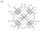
- the haptic device 10 includes a housing 20, four vibrating bodies 30, and a control device 40. As shown in FIG. The housing 20 is spherical as a whole. The diameter of the housing 20 is about 5 cm or more and 30 cm or less. That is, the housing 20 has a size that allows the user to grasp it by hand.
- the four vibrating bodies 30 are positioned inside the housing 20 . Although details are omitted, the four vibrating bodies 30 are fixed inside the housing 20 . As shown in FIG. 2, a virtual plane passing through at least three vibrating bodies 30 is assumed to be a virtual plane VP. In this embodiment, the virtual plane VP passes through four vibrating bodies 30, that is, all vibrating bodies 30. FIG. The virtual plane VP passes through the center of gravity G of the housing 20 .
- the center of gravity G of the housing 20 coincides with the geometric center of the housing 20 when the housing 20 is viewed in a direction orthogonal to the virtual plane VP. That is, the center of gravity G is the center of the spherical casing 20 .
- a first reference axis X is defined as an axis passing through the center of gravity G of the housing 20 and parallel to the virtual plane VP.
- a second reference axis Y is defined as an axis perpendicular to the first reference axis X and parallel to the virtual plane VP. Therefore, the virtual plane VP is a plane containing the first reference axis X and the second reference axis Y.
- the third reference axis Z is an axis that passes through the center of gravity G of the housing 20 and is perpendicular to the virtual plane VP.
- one of the directions along the first reference axis X is defined as a first positive direction X1
- the direction opposite to the first positive direction X1 is defined as a first negative direction X2.
- One of the directions along the second reference axis Y is defined as a second positive direction Y1, and the direction opposite to the second positive direction Y1 is defined as a second negative direction Y2.
- one of the directions along the third reference axis Z is defined as a third positive direction Z1, and the direction opposite to the third positive direction Z1 is defined as a third negative direction Z2.
- the vibrating body 30 has a substantially cubic shape.
- the vibrating body 30 is configured to vibrate in directions along two reference axes.
- the vibrating body 30 includes two voice coil motors, weights corresponding to the respective voice coil motors, and a cubic case that houses them.
- the weight vibrates due to the force generated as the current flows through the coil of the voice coil motor.
- the case vibrates due to the vibration of the weight.
- the four vibrating bodies 30 are a first vibrating body 31, a second vibrating body 32, a third vibrating body 33, and a fourth vibrating body .
- the first vibrating body 31 is positioned on the first reference axis X.
- the first vibrating body 31 is positioned on the first positive direction X1 side with respect to the center of gravity G.
- the first reference axis X is a virtual straight line passing through the first vibrating body 31 and the second vibrating body 32 .
- the second vibrating body 32 is positioned on the first reference axis X. Also, the second vibrating body 32 is located on the first negative direction X2 side with respect to the center of gravity G. As shown in FIG. The distance from the second vibrating body 32 to the center of gravity G is equal to the distance from the first vibrating body 31 to the center of gravity G. There are two directions of vibration of the second vibrating body 32: a direction along the second reference axis Y and a direction along the third reference axis Z. As shown in FIG.
- the third vibrating body 33 is positioned on the second reference axis Y. Also, the third vibrating body 33 is located on the second positive direction Y1 side with respect to the center of gravity G. As shown in FIG. The distance from the third vibrating body 33 to the center of gravity G is equal to the distance from the first vibrating body 31 to the center of gravity G. There are two directions of vibration of the third vibrating body 33, namely, a direction along the first reference axis X and a direction along the third reference axis Z. As shown in FIG.
- the fourth vibrating body 34 is positioned on the second reference axis Y. Also, the fourth vibrating body 34 is positioned on the second negative direction Y2 side with respect to the center of gravity G. As shown in FIG. The distance from the fourth vibrating body 34 to the center of gravity G is equal to the distance from the first vibrating body 31 to the center of gravity G. There are two directions of vibration of the fourth vibrating body 34, namely, a direction along the first reference axis X and a direction along the third reference axis Z. As shown in FIG.
- the third vibrating body 33 and the fourth vibrating body 34 are positioned on the second reference axis Y, while the first vibrating body 31 and the second vibrating body 32 pass along the first reference axis X. not located.
- the arrangement of the plurality of vibrating bodies 30 is such that three or more vibrating bodies 30 are not positioned on the same imaginary straight line.
- each vibrating body 30 is positioned on either the first reference axis X or the second reference axis Y. As shown in FIG. That is, the four vibrating bodies 30 are positioned on the virtual plane VP.
- the control device 40 is located inside the housing 20 . 2 to 5, illustration of the control device 40 is omitted.
- the control device 40 includes a CPU and a ROM, and executes software processing.
- the control device 40 is connected to each vibrator 30 by a signal line. By controlling the vibration pattern of each vibrating body 30, it is possible to present a force sensation in a specific direction from each vibrating body 30.
- FIG. Although illustration is omitted, the force sense presentation device 10 includes a battery.
- the battery is located inside the housing 20 .
- the battery is connected to the control device 40 and each vibrator 30 by power lines. The battery supplies power to the control device 40 and each vibrator 30 .
- control mode The control device 40 can execute three control modes. Thereby, the user who grips the housing 20 can feel three kinds of force sensations. All of the three kinds of haptic sensations are haptic sensations that cause the housing 20 to rotate, but the virtual rotation axis of the housing 20 is different. In each control mode, the combinations of the directions of the force sensation presented by the plurality of vibrating bodies 30 are different from each other. Further, in each control mode, the magnitudes of the force sensations presented by the plurality of vibrating bodies 30 are all the same.
- the three control modes are a first control mode, a second control mode and a third control mode.
- the direction of the force sense presented by the first vibrating body 31 be the first direction D1.
- the direction of the force sense presented by the second vibrating body 32 is defined as a second direction D2.
- the direction of the force sense presented by the third vibrating body 33 is defined as a third direction D3.
- the direction of force sense presented by the fourth vibrating body 34 is defined as a fourth direction D4.
- the control device 40 changes the vibration pattern of the first vibrating body 31 so that the first direction D1 is the third negative direction Z2, i.e., the depth direction in FIG. Control.
- the control device 40 controls the vibration pattern of the second vibrating body 32 so that the second direction D2 is the third positive direction Z1, that is, the front side of the drawing in FIG.
- the control device 40 controls the vibration pattern of the third vibrating body 33 so that the third direction D3 is the third negative direction Z2.
- the control device 40 controls the vibration pattern of the fourth vibrating body 34 so that the fourth direction D4 is the third positive direction Z1.
- the first direction D1 intersects the virtual plane VP.
- the second direction D2 intersects the virtual plane VP.
- the third direction D3 intersects the virtual plane VP.
- the fourth direction D4 intersects the virtual plane VP.
- the first direction D1 is opposite to the second direction D2. Therefore, the first direction D1 is the direction opposite to the second direction D2 across the virtual plane VP.
- the third direction D3 is the same direction as the first direction D1. Therefore, the third direction D3 is on the same side as the first direction D1 across the virtual plane VP. Further, the fourth direction D4 is the same direction as the second direction D2. Therefore, the fourth direction D4 is on the same side as the second direction D2 across the virtual plane VP.
- the control device 40 controls the vibration pattern of the first vibrating body 31 so that the first direction D1 is the third positive direction Z1.
- the control device 40 controls the vibration pattern of the second vibrating body 32 so that the second direction D2 is the third negative direction Z2.
- the control device 40 controls the vibration pattern of the third vibrating body 33 so that the third direction D3 is the third negative direction Z2.
- the control device 40 controls the vibration pattern of the fourth vibrating body 34 so that the fourth direction D4 is the third positive direction Z1.
- the first direction D1 intersects the virtual plane VP.
- the second direction D2 intersects the virtual plane VP.
- the third direction D3 intersects the virtual plane VP.
- the fourth direction D4 intersects the virtual plane VP.
- the first direction D1 is opposite to the third direction D3. Therefore, the first direction D1 is the direction opposite to the third direction D3 across the virtual plane VP.
- the second direction D2 is the same direction as the third direction D3. Therefore, the second direction D2 is on the same side as the third direction D3 across the virtual plane VP.
- the fourth direction D4 is the same direction as the first direction D1. Therefore, the fourth direction D4 is on the same side as the first direction D1 across the virtual plane VP.
- the control device 40 controls the third direction D3 and the fourth direction D4 in the same manner as in the first control mode.
- the control device 40 controls the vibration pattern of the first vibrating body 31 so that the first direction D1 is the second negative direction Y2.
- the control device 40 controls the vibration pattern of the second vibrating body 32 so that the second direction D2 is the second positive direction Y1.
- the control device 40 controls the vibration pattern of the third vibrating body 33 so that the third direction D3 is the first positive direction X1.
- the control device 40 controls the vibration pattern of the fourth vibrating body 34 so that the fourth direction D4 is the first negative direction X2.
- the first direction D1 to the fourth direction D4 are parallel to the virtual plane VP.
- the first direction D1 and the second direction D2 are directions orthogonal to the first reference axis X.
- the first direction D1 is opposite to the second direction D2. Therefore, the first direction D1 is the direction opposite to the second direction D2 with the first reference axis X passing through the first vibrating body 31 and the second vibrating body 32 interposed therebetween.
- the third direction D3 and the fourth direction D4 are directions perpendicular to the second reference axis Y in the third control mode. Furthermore, the third direction D3 is opposite to the fourth direction D4. Therefore, the third direction D3 is the direction opposite to the fourth direction D4 with the second reference axis Y passing through the third vibrating body 33 and the fourth vibrating body 34 interposed therebetween.
- the control device 40 controls each vibrator 30 in each of the control modes described above while the user holds the housing 20 of the force sense presentation device 10 by hand. A user's hand is given a haptic sensation from each vibrator 30 from the housing 20 .
- the first direction D1 and the third direction D3 are the third negative direction Z2.
- the second direction D2 and the fourth direction D4 are the third positive direction Z1.
- the first virtual axis R1 passes through the center of gravity G and extends on the virtual plane VP.
- a first virtual axis R1 passes between the first vibrating body 31 and the fourth vibrating body 34 .
- the first virtual axis R ⁇ b>1 passes between the second vibrating body 32 and the third vibrating body 33 .
- the acute angle formed by the first virtual axis R1 and the first reference axis X is 45 degrees.
- the acute angle formed by the first virtual axis R1 and the second reference axis Y is 45 degrees.
- the first direction D1 and the fourth direction D4 are the third positive direction Z1.
- the second direction D2 and the third direction D3 are the third negative direction Z2.
- the second virtual axis R2 passes through the center of gravity G and extends on the virtual plane VP.
- a second virtual axis R2 passes between the first vibrating body 31 and the third vibrating body 33 .
- the second virtual axis R ⁇ b>2 passes between the second vibrating body 32 and the fourth vibrating body 34 .
- the second virtual axis R2 is orthogonal to the first virtual axis R1.
- the first direction D1 is the second negative direction Y2.
- the second direction D2 is the second positive direction Y1.
- the third direction D3 is the first positive direction X1.
- the fourth direction D4 is the first negative direction X2.
- the control device 40 can execute each vibrator 30 in the first control mode and the second control mode.
- the user's hand is given a haptic sensation that the housing 20 rotates about the first virtual axis R1 as the rotation axis.
- the user's hand is given a haptic sensation that the housing 20 rotates about the second virtual axis R2 as the rotation axis.
- the first virtual axis R ⁇ b>1 extends between the first vibrating body 31 and the second vibrating body 32 and between the second vibrating body 32 and the third vibrating body 33 .
- the second virtual axis R ⁇ b>2 extends between the first vibrating body 31 and the third vibrating body 33 and between the first vibrating body 31 and the second vibrating body 32 . Therefore, the haptic presentation device 10 can change the virtual rotation axis of the haptic presentation device 10 to a different axis by switching between the first control mode and the second control mode.
- the control device 40 can further execute each vibrator 30 in the third control mode.
- the user's hand is given a haptic sensation as if the housing 20 were rotating about the third virtual axis R3.
- the third virtual axis R3 extends orthogonally to the virtual plane VP. Therefore, by switching to the third control mode, the haptic presentation device 10 further changes the virtual rotation axis of the rotating haptic in both the first control mode and the second control mode. axis can be changed.
- the haptic device 10 can provide the user with a haptic sensation that the housing 20 rotates not only about the axis extending on the virtual plane VP but also about the axis orthogonal to the virtual plane VP.
- the force sense presentation device 10 includes four vibrators 30 . Therefore, compared to the case where only three vibrators 30 are provided, it is easier to set the rotation axes in each control mode so as to be orthogonal to each other.
- the virtual plane VP passes through all vibrating bodies 30 . Therefore, the first virtual axis R1, which is the rotation axis in the first control mode, and the second virtual axis R2, which is the rotation axis in the second control mode, pass through the center of the range surrounded by the vibrating bodies 30 on the virtual plane VP. It becomes easier to set
- the distances from the respective vibrating bodies 30 to the center of gravity G are all equal on the virtual plane VP. Therefore, it becomes easy to adjust the rotation axis of each control mode so that it passes through the center of gravity G while the force sensation presented by each vibrating body 30 is the same.
- the control device 40 controls all the vibrating bodies 30 to present the same force sensation. Therefore, compared to the case where the control device 40 presents force sensations of different magnitudes from the vibrating bodies 30 so that the rotation axis of each control mode passes through the center of gravity G, simple control is sufficient.
- the shape of the housing 20 is not limited to a spherical shape.
- the housing 20 may be columnar or polygonal, for example.
- the housing 20 may be at least gripped by the user's hand.
- the housing 20 may be held by both hands of the user.
- the haptic presentation device 110 of the modified example shown in FIG. 6 is applied to a game controller.
- the housing 120 of the haptic device 110 has two grips 121 .
- One grip portion 121 is held by the user's right hand.
- the other grip 121 is held by the user's left hand.
- Two vibrating bodies 30 are positioned on each grip portion 121 .
- the control device 40 may be located outside the housing 20 .
- the control device 40 is not limited to a device that includes a CPU and a ROM and executes software processing.
- a dedicated hardware circuit for example, ASIC, etc.
- the control device 40 may have any one of the following configurations (a) to (c).
- (c) have dedicated hardware circuitry to perform all of the above processing;
- the control device 40 does not have to execute the third control mode. At least, the control device 40 should be capable of executing the first control mode and the second control mode. - The control device 40 may control the magnitude of the force sense presented from each vibrator 30 differently. For example, when the distance from each vibrating body 30 to the center of gravity G is different, the control device 40 may perform control so that the magnitude of the force sensation presented from each vibrating body 30 differs according to the distance from the center of gravity G. good.
- the control device 40 may further execute a control mode that gradually weakens the vibration pattern of some of the vibrating bodies 30 from the state of the first control mode.
- this control mode for example, the control device 40 gradually weakens the vibration modes of the first vibrating body 31 and the second vibrating body 32 from the state of the first control mode.
- the first virtual axis R1 changes so as to gradually approach the first reference axis X.
- FIG. Therefore, in this control mode, the user feels that the rotation axis in the sense of rotation changes on the virtual plane VP.
- the control device 40 may further execute a control mode in which the vibration pattern of some of the vibrating bodies 30 is gradually weakened from the state of the second control mode.
- the first direction D1 and the second direction D2 only need to be opposite to the second direction D2 across the virtual plane VP. Therefore, the first direction D1 does not have to be opposite to the second direction D2.
- the first direction D1 may be inclined with respect to the third negative direction Z2.
- the second direction D2 may be inclined with respect to the third positive direction Z1.
- the third direction D3 may be a direction on the same side of the virtual plane VP as the first direction D1 or a direction parallel to the virtual plane VP.
- the third direction D3 may not be the same direction as the first direction D1.
- the third direction D3 may be inclined with respect to the third negative direction Z2.
- the third direction D3 may be a direction parallel to the virtual plane VP.
- the first virtual axis R1 and the second virtual axis R2 are different axes, so that the haptic device 10 can switch between the first control mode and the second control mode to achieve the desired force.
- the virtual axis of rotation of the visual presentation device 10 can be changed to a different axis.
- the first direction D1 and the third direction D3 only need to be opposite to the third direction D3 across the virtual plane VP. Therefore, the first direction D1 does not have to be opposite to the third direction D3.
- the first direction D1 may be inclined with respect to the third positive direction Z1.
- the third direction D3 may be inclined with respect to the third negative direction Z2.
- the second direction D2 may be a direction on the same side of the virtual plane VP as the third direction D3 or a direction parallel to the virtual plane VP.
- the second direction D2 is on the same side of the virtual plane VP as the first direction D1
- the second direction D2 does not have to be on the same side as the third direction D3.
- the second direction D2 may be inclined with respect to the third negative direction Z2.
- the second direction D2 may be a direction parallel to the virtual plane VP.
- the first virtual axis R1 and the second virtual axis R2 are different axes, so that the haptic device 10 can switch between the first control mode and the second control mode to achieve the desired force.
- the virtual axis of rotation of the visual presentation device 10 can be changed to a different axis.
- the third direction D3 is not limited to the example of the above embodiment.
- the third direction D3 may intersect the virtual plane VP, or the third direction D3 may be absent because the force sense is not presented from the third vibrating body 33 .
- the fourth direction D4 is not limited to the example of the above embodiment.
- the fourth direction D ⁇ b>4 may be any direction, and the fourth direction D ⁇ b>4 may not exist because the force sense is not presented from the fourth vibrating body 34 .
- the control device 40 may execute control modes other than the first to third control modes.
- the force sense of rotating the housing 20 about another virtual axis different from the first virtual axis R1 to the third virtual axis R3 as the rotation axis is generated. can give. Further, depending on the combination of the directions of the force sense of each vibrating body 30, it is possible to give the sense of force as if the housing 20 were to move linearly.
- the control device 40 may control the vibration pattern of each vibrator 30 in each control mode. In this case, it does not matter whether the vibrating body 30 is actually vibrating. Controlling the vibration pattern of each vibrating body 30 also includes intentionally not vibrating some of the vibrating bodies 30 .
- the configuration of the vibrating body 30 is not limited to that of the above embodiment.
- the vibrating body 30 may use vibration by a motor, or may have a piezo element.
- the number of vibrating bodies 30 may be three, or may be five or more.
- a specific one of the plurality of vibrating bodies 30 is defined as a first vibrating body 31, a specific one other than the first vibrating body 31 is defined as a second vibrating body 32, and the first vibrating body 31 and the second vibrating body A specific one other than the body 32 may be used as the third vibrating body 33 .
- the control device 40 may control each vibrator 30 in the first control mode and the second control mode.
- the position of the vibrating body 30 is not limited to the example of the above embodiment.
- the virtual plane VP does not have to pass through the fourth vibrating body 34 . That is, the fourth vibrating body 34 may be positioned at a location through which the virtual plane VP does not pass. Even in this case, the virtual plane VP is defined as a virtual plane on which at least three vibrating bodies 30 exist.
- the second vibrating body 32 does not have to be on the first reference axis X, and the distance from the second vibrating body 32 to the center of gravity G is different from the distance from the first vibrating body 31 to the center of gravity G.
- the third vibrating body 33 does not have to be on the second reference axis Y, and the distance from the third vibrating body 33 to the center of gravity G is different from the distance from the first vibrating body 31 to the center of gravity G.
- the fourth vibrating body 34 does not have to be on the second reference axis Y, and the distance from the fourth vibrating body 34 to the center of gravity G is different from the distance from the first vibrating body 31 to the center of gravity G.
- the virtual plane VP on which the at least three vibrating bodies 30 exist does not have to pass through the center of gravity G of the housing 20 .
- the virtual plane VP may be shifted from the center of gravity G toward the third positive direction Z1 or the third negative direction Z2.
Abstract
A first direction (D1) is defined as the direction of force sense presented by a first vibrating member (31) among a plurality of vibrating members (30). A second direction (D2) is defined as the direction of force sense presented by a second vibrating member (32) among the plurality of vibrating members (30). A third direction (D2) is defined as the direction of force sense presented by a third vibrating member (33) among the plurality of vibrating members (30). A control device is capable of executing a first control pattern for controlling the vibration pattern of each of the vibrating members (30) such that both of the first direction (D1) and the third direction (D3) face the side reverse to the second direction (D2) across a virtual plane (VP). The control device is also capable of executing a second control pattern for controlling the vibration pattern of each of the vibrating members (30) such that the first direction (D1) faces the side reverse to both the second direction (D2) and the third direction (D3) across the virtual plane (VP).
Description
本発明は、力覚提示装置に関する。
The present invention relates to a haptic presentation device.
特許文献1に記載の力覚提示装置は、筐体と、振動体と、制御装置と、を備えている。振動体は、筐体の内部に位置している。筐体は、例えば使用者の手に握られて使用される。制御装置は、振動体の振動パターンを制御することにより、特定の方向に向かう力覚を提示する。これにより、筐体を握っている使用者は、力覚提示装置が特定の方向に移動しているかのような力覚を感じる。
The force sense presentation device described in Patent Document 1 includes a housing, a vibrator, and a control device. The vibrator is located inside the housing. The housing is used, for example, by being held in the user's hand. The control device presents a force sense in a specific direction by controlling the vibration pattern of the vibrator. As a result, the user gripping the housing feels a sense of force as if the force sense device were moving in a specific direction.
特許文献1に記載のような力覚提示装置において、振動体が1つのみであると、使用者に対して与えられる力覚は、特定の方向に限られる。つまり、特許文献1の力覚提示装置は、当該力覚提示装置が回転しているかのような力覚を提示したり、力覚提示装置が発生する力覚の仮想の回転軸を様々に変更したりすることはできない。
In the haptic presentation device as described in Patent Document 1, if there is only one vibrator, the haptic given to the user is limited to a specific direction. In other words, the haptic presentation device of Patent Document 1 presents a haptic sensation as if the haptic presentation device is rotating, and variously changes the virtual rotation axis of the haptic sensation generated by the haptic presentation device. You can't do it.
上記課題を解決するため、本発明は、使用者が手で掴むことが可能な筐体と、前記筐体の内部に位置している3つ以上の振動体と、前記各振動体の振動パターンを制御することにより前記各振動体から力覚を提示可能である制御装置と、を備え、複数の前記振動体の配置は、同一の仮想直線上に3つ以上の前記振動体が位置しないようになっており、複数の前記振動体のうちの特定の1つを第1振動体とし、前記第1振動体が提示する力覚の方向を第1方向とし、複数の前記振動体のうちの前記第1振動体とは異なる特定の1つを第2振動体とし、前記第2振動体が提示する力覚の方向を第2方向とし、複数の前記振動体のうちの前記第1振動体及び前記第2振動体とは異なる特定の1つを第3振動体とし、前記第3振動体が提示する力覚の方向を第3方向とし、前記第1振動体、前記第2振動体、及び前記第3振動体を通る仮想の平面を仮想平面としたとき、前記制御装置は、前記第1方向と前記第2方向とが前記仮想平面に交差しており、且つ、前記第1方向が前記仮想平面を挟んで前記第2方向と反対側の方向となるように、且つ、前記第3方向が前記仮想平面を挟んで前記第1方向と同一側の方向又は前記仮想平面に平行な方向となるように、前記各振動体の振動パターンを制御する第1制御モードと、前記第1方向と前記第3方向とが前記仮想平面に交差しており、且つ、前記第1方向が前記仮想平面を挟んで前記第3方向と反対側の方向となるように、且つ、前記第2方向が前記仮想平面を挟んで前記第3方向と同一側の方向又は前記仮想平面に平行な方向となるように、前記各振動体の振動パターンを制御する第2制御モードと、を実行可能である力覚提示装置である。
In order to solve the above problems, the present invention provides a housing that can be gripped by a user's hand, three or more vibrating bodies positioned inside the housing, and a vibration pattern of each of the vibrating bodies. and a control device capable of presenting a force sensation from each of the vibrating bodies by controlling the arrangement of the plurality of vibrating bodies so that three or more of the vibrating bodies are not positioned on the same imaginary straight line. A specific one of the plurality of vibrating bodies is defined as a first vibrating body, the direction of the force sense presented by the first vibrating body is defined as a first direction, and one of the plurality of vibrating bodies is A specific one different from the first vibrating body is defined as a second vibrating body, the direction of force sensation presented by the second vibrating body is defined as a second direction, and the first vibrating body among the plurality of vibrating bodies and a specific one different from the second vibrating body is defined as a third vibrating body, the direction of the force sense presented by the third vibrating body is defined as a third direction, the first vibrating body, the second vibrating body, and the virtual plane passing through the third vibrating body is defined as a virtual plane, the control device is configured such that the first direction and the second direction intersect the virtual plane, and the first direction is A direction opposite to the second direction across the virtual plane, and the third direction is on the same side of the virtual plane as the first direction or a direction parallel to the virtual plane so that the first control mode for controlling the vibration pattern of each vibrator, the first direction and the third direction intersect the virtual plane, and the first direction is the virtual plane A direction opposite to the third direction across a plane, and the second direction is a direction on the same side as the third direction across the virtual plane or a direction parallel to the virtual plane. and a second control mode for controlling the vibration pattern of each vibrator.
上記構成によれば、制御装置は、第1制御モードと第2制御モードとで、各振動体を実行可能である。第1制御モード及び第2制御モードのいずれの場合でも、力覚提示装置は、回転するような力覚を使用者に提示する。そして、力覚提示装置は、第1制御モードと第2制御モードとを切り替えることで、力覚提示装置の仮想の回転軸を、異なる軸に変更できる。
According to the above configuration, the control device can execute each vibrator in the first control mode and the second control mode. In both the first control mode and the second control mode, the force sense presentation device presents the user with a force sense of rotation. By switching between the first control mode and the second control mode, the haptic presentation device can change the virtual rotation axis of the haptic presentation device to a different axis.
力覚提示装置が発生する力覚の仮想の回転軸を変更できる。
You can change the virtual rotation axis of the haptic sensation generated by the haptic presentation device.
<一実施形態について>
以下、力覚提示装置の一実施形態について、図面を参照して説明する。なお、図面は、理解を容易にするために構成要素を拡大して示している場合がある。構成要素の寸法比率は、実際のものと、又は別の図面中のものと異なる場合がある。 <About one embodiment>
An embodiment of a haptic presentation device will be described below with reference to the drawings. It should be noted that the drawings may show constituent elements in an enlarged manner in order to facilitate understanding. The dimensional ratios of components may differ from those in reality or in other drawings.
(全体構成)
図1に示すように、力覚提示装置10は、筐体20と、4つの振動体30と、制御装置40と、を備えている。筐体20は、全体として球状である。筐体20の直径は、5cm以上30cm以下程度である。すなわち、筐体20は、使用者が手で掴むことが可能な大きさである。 (overall structure)
As shown in FIG. 1, thehaptic device 10 includes a housing 20, four vibrating bodies 30, and a control device 40. As shown in FIG. The housing 20 is spherical as a whole. The diameter of the housing 20 is about 5 cm or more and 30 cm or less. That is, the housing 20 has a size that allows the user to grasp it by hand.
図1に示すように、力覚提示装置10は、筐体20と、4つの振動体30と、制御装置40と、を備えている。筐体20は、全体として球状である。筐体20の直径は、5cm以上30cm以下程度である。すなわち、筐体20は、使用者が手で掴むことが可能な大きさである。 (overall structure)
As shown in FIG. 1, the
4つの振動体30は、筐体20の内部に位置している。4つの振動体30は、詳細は省略するが、筐体20の内部に固定されている。図2に示すように、少なくとも3つの振動体30を通る仮想の平面を仮想平面VPとする。本実施形態では、仮想平面VPは、4つの振動体30、つまりすべての振動体30を通過している。仮想平面VPは、筐体20の重心Gを通っている。
The four vibrating bodies 30 are positioned inside the housing 20 . Although details are omitted, the four vibrating bodies 30 are fixed inside the housing 20 . As shown in FIG. 2, a virtual plane passing through at least three vibrating bodies 30 is assumed to be a virtual plane VP. In this embodiment, the virtual plane VP passes through four vibrating bodies 30, that is, all vibrating bodies 30. FIG. The virtual plane VP passes through the center of gravity G of the housing 20 .
図3に示すように、筐体20の重心Gは、仮想平面VPに直交する方向を向いて筐体20を視たときの筐体20の幾何中心に一致する。つまり、重心Gは、球状の筐体20の中心である。筐体20の重心Gを通り、且つ仮想平面VPに平行な軸を、第1基準軸Xとする。また、第1基準軸Xに直交し、且つ仮想平面VPに平行な軸を、第2基準軸Yとする。したがって、仮想平面VPは、第1基準軸X及び第2基準軸Yを含む面である。さらに、図2に示すように、筐体20の重心Gを通り、且つ仮想平面VPに垂直な軸を、第3基準軸Zとする。そして、図3に示すように、第1基準軸Xに沿う方向の一方を第1正方向X1とし、第1正方向X1と反対方向を第1負方向X2とする。また、第2基準軸Yに沿う方向の一方を第2正方向Y1とし、第2正方向Y1と反対方向を第2負方向Y2とする。さらに、図2に示すように、第3基準軸Zに沿う方向の一方を第3正方向Z1とし、第3正方向Z1と反対方向を第3負方向Z2とする。
As shown in FIG. 3, the center of gravity G of the housing 20 coincides with the geometric center of the housing 20 when the housing 20 is viewed in a direction orthogonal to the virtual plane VP. That is, the center of gravity G is the center of the spherical casing 20 . A first reference axis X is defined as an axis passing through the center of gravity G of the housing 20 and parallel to the virtual plane VP. A second reference axis Y is defined as an axis perpendicular to the first reference axis X and parallel to the virtual plane VP. Therefore, the virtual plane VP is a plane containing the first reference axis X and the second reference axis Y. FIG. Furthermore, as shown in FIG. 2, the third reference axis Z is an axis that passes through the center of gravity G of the housing 20 and is perpendicular to the virtual plane VP. As shown in FIG. 3, one of the directions along the first reference axis X is defined as a first positive direction X1, and the direction opposite to the first positive direction X1 is defined as a first negative direction X2. One of the directions along the second reference axis Y is defined as a second positive direction Y1, and the direction opposite to the second positive direction Y1 is defined as a second negative direction Y2. Further, as shown in FIG. 2, one of the directions along the third reference axis Z is defined as a third positive direction Z1, and the direction opposite to the third positive direction Z1 is defined as a third negative direction Z2.
図3に示すように、振動体30は、略立方体状である。振動体30は、2つの基準軸に沿う方向に振動可能に構成されている。図示は省略するが、振動体30は、2つのボイスコイルモータと、各ボイスコイルモータに対応した錘と、これらを収容する立方体状のケースと、を備えている。ボイスコイルモータのコイルに電流が流れることに伴って発生する力により、錘が振動する。錘が振動すると、ケースが錘の振動によって振動する。
As shown in FIG. 3, the vibrating body 30 has a substantially cubic shape. The vibrating body 30 is configured to vibrate in directions along two reference axes. Although not shown, the vibrating body 30 includes two voice coil motors, weights corresponding to the respective voice coil motors, and a cubic case that houses them. The weight vibrates due to the force generated as the current flows through the coil of the voice coil motor. When the weight vibrates, the case vibrates due to the vibration of the weight.
4つの振動体30は、第1振動体31と、第2振動体32と、第3振動体33と、第4振動体34と、である。第1振動体31は、第1基準軸X上に位置している。また、第1振動体31は、重心Gに対して第1正方向X1側に位置している。そして、第1振動体31の振動の方向は、第2基準軸Yに沿う方向及び第3基準軸Zに沿う方向の2種類である。本実施形態では、第1基準軸Xは、第1振動体31及び第2振動体32を通る仮想直線である。
The four vibrating bodies 30 are a first vibrating body 31, a second vibrating body 32, a third vibrating body 33, and a fourth vibrating body . The first vibrating body 31 is positioned on the first reference axis X. As shown in FIG. Also, the first vibrating body 31 is positioned on the first positive direction X1 side with respect to the center of gravity G. As shown in FIG. There are two directions of vibration of the first vibrating body 31, namely, a direction along the second reference axis Y and a direction along the third reference axis Z. As shown in FIG. In this embodiment, the first reference axis X is a virtual straight line passing through the first vibrating body 31 and the second vibrating body 32 .
第2振動体32は、第1基準軸X上に位置している。また、第2振動体32は、重心Gに対して第1負方向X2側に位置している。第2振動体32から重心Gまでの距離は、第1振動体31から重心Gまでの距離に等しくなっている。第2振動体32の振動の方向は、第2基準軸Yに沿う方向及び第3基準軸Zに沿う方向の2種類である。
The second vibrating body 32 is positioned on the first reference axis X. Also, the second vibrating body 32 is located on the first negative direction X2 side with respect to the center of gravity G. As shown in FIG. The distance from the second vibrating body 32 to the center of gravity G is equal to the distance from the first vibrating body 31 to the center of gravity G. There are two directions of vibration of the second vibrating body 32: a direction along the second reference axis Y and a direction along the third reference axis Z. As shown in FIG.
第3振動体33は、第2基準軸Y上に位置している。また、第3振動体33は、重心Gに対して第2正方向Y1側に位置している。第3振動体33から重心Gまでの距離は、第1振動体31から重心Gまでの距離に等しくなっている。第3振動体33の振動の方向は、第1基準軸Xに沿う方向及び第3基準軸Zに沿う方向の2種類である。
The third vibrating body 33 is positioned on the second reference axis Y. Also, the third vibrating body 33 is located on the second positive direction Y1 side with respect to the center of gravity G. As shown in FIG. The distance from the third vibrating body 33 to the center of gravity G is equal to the distance from the first vibrating body 31 to the center of gravity G. There are two directions of vibration of the third vibrating body 33, namely, a direction along the first reference axis X and a direction along the third reference axis Z. As shown in FIG.
第4振動体34は、第2基準軸Y上に位置している。また、第4振動体34は、重心Gに対して第2負方向Y2側に位置している。第4振動体34から重心Gまでの距離は、第1振動体31から重心Gまでの距離に等しくなっている。第4振動体34の振動の方向は、第1基準軸Xに沿う方向及び第3基準軸Zに沿う方向の2種類である。
The fourth vibrating body 34 is positioned on the second reference axis Y. Also, the fourth vibrating body 34 is positioned on the second negative direction Y2 side with respect to the center of gravity G. As shown in FIG. The distance from the fourth vibrating body 34 to the center of gravity G is equal to the distance from the first vibrating body 31 to the center of gravity G. There are two directions of vibration of the fourth vibrating body 34, namely, a direction along the first reference axis X and a direction along the third reference axis Z. As shown in FIG.
以上のように、第3振動体33及び第4振動体34は第2基準軸Y上に位置している一方、第1振動体31及び第2振動体32が通る第1基準軸X上に位置していない。つまり、複数の振動体30の配置は、同一の仮想直線上に3つ以上の振動体30が位置しないようになっている。また、各振動体30は、第1基準軸X又は第2基準軸Yのいずれかの軸上に位置している。すなわち、4つの振動体30は、仮想平面VP上に位置している。
As described above, the third vibrating body 33 and the fourth vibrating body 34 are positioned on the second reference axis Y, while the first vibrating body 31 and the second vibrating body 32 pass along the first reference axis X. not located. In other words, the arrangement of the plurality of vibrating bodies 30 is such that three or more vibrating bodies 30 are not positioned on the same imaginary straight line. Also, each vibrating body 30 is positioned on either the first reference axis X or the second reference axis Y. As shown in FIG. That is, the four vibrating bodies 30 are positioned on the virtual plane VP.
制御装置40は、筐体20の内部に位置している。また、図2~図5では、制御装置40の図示を省略している。制御装置40は、CPUとROMとを備えて、ソフトウェア処理を実行する。制御装置40は、制御装置40は、各振動体30に、信号線で繋がっている。各振動体30の振動パターンを制御することにより、各振動体30から特定の方向への力覚を提示可能である。なお、図示は省略するが、力覚提示装置10は、バッテリを備えている。バッテリは筐体20の内部に位置している。バッテリは、制御装置40及び各振動体30に電力線で繋がっている。バッテリは、制御装置40及び各振動体30に電力を供給する。
The control device 40 is located inside the housing 20 . 2 to 5, illustration of the control device 40 is omitted. The control device 40 includes a CPU and a ROM, and executes software processing. The control device 40 is connected to each vibrator 30 by a signal line. By controlling the vibration pattern of each vibrating body 30, it is possible to present a force sensation in a specific direction from each vibrating body 30. FIG. Although illustration is omitted, the force sense presentation device 10 includes a battery. The battery is located inside the housing 20 . The battery is connected to the control device 40 and each vibrator 30 by power lines. The battery supplies power to the control device 40 and each vibrator 30 .
(制御モード)
制御装置40は、3つの制御モードを実行可能である。これにより、筐体20を掴む使用者は、3種類の力覚を感じることができる。3種類の力覚はいずれも筐体20が回転するような力覚であるが、それぞれ筐体20の仮想の回転軸が異なる。各制御モードでは、複数の振動体30から提示する力覚の方向の組み合わせが互いに異なっている。また、各制御モードでは、複数の振動体30から提示する力覚の大きさはすべて同じ大きさである。3つの制御モードは、第1制御モード、第2制御モード、及び第3制御モードである。 (control mode)
Thecontrol device 40 can execute three control modes. Thereby, the user who grips the housing 20 can feel three kinds of force sensations. All of the three kinds of haptic sensations are haptic sensations that cause the housing 20 to rotate, but the virtual rotation axis of the housing 20 is different. In each control mode, the combinations of the directions of the force sensation presented by the plurality of vibrating bodies 30 are different from each other. Further, in each control mode, the magnitudes of the force sensations presented by the plurality of vibrating bodies 30 are all the same. The three control modes are a first control mode, a second control mode and a third control mode.
制御装置40は、3つの制御モードを実行可能である。これにより、筐体20を掴む使用者は、3種類の力覚を感じることができる。3種類の力覚はいずれも筐体20が回転するような力覚であるが、それぞれ筐体20の仮想の回転軸が異なる。各制御モードでは、複数の振動体30から提示する力覚の方向の組み合わせが互いに異なっている。また、各制御モードでは、複数の振動体30から提示する力覚の大きさはすべて同じ大きさである。3つの制御モードは、第1制御モード、第2制御モード、及び第3制御モードである。 (control mode)
The
ここで、第1振動体31が提示する力覚の方向を第1方向D1とする。第2振動体32が提示する力覚の方向を第2方向D2とする。第3振動体33が提示する力覚の方向を第3方向D3とする。第4振動体34が提示する力覚の方向を第4方向D4とする。
Here, let the direction of the force sense presented by the first vibrating body 31 be the first direction D1. The direction of the force sense presented by the second vibrating body 32 is defined as a second direction D2. The direction of the force sense presented by the third vibrating body 33 is defined as a third direction D3. The direction of force sense presented by the fourth vibrating body 34 is defined as a fourth direction D4.
図3に示すように、第1制御モードにおいて、制御装置40は、第1方向D1を第3負方向Z2、すなわち図3において紙面奥方向とするように、第1振動体31の振動パターンを制御する。第1制御モードにおいて、制御装置40は、第2方向D2を第3正方向Z1、すなわち図3において紙面手前方向とするように、第2振動体32の振動パターンを制御する。第1制御モードにおいて、制御装置40は、第3方向D3を第3負方向Z2とするように、第3振動体33の振動パターンを制御する。第1制御モードにおいて、制御装置40は、第4方向D4を第3正方向Z1とするように、第4振動体34の振動パターンを制御する。
As shown in FIG. 3, in the first control mode, the control device 40 changes the vibration pattern of the first vibrating body 31 so that the first direction D1 is the third negative direction Z2, i.e., the depth direction in FIG. Control. In the first control mode, the control device 40 controls the vibration pattern of the second vibrating body 32 so that the second direction D2 is the third positive direction Z1, that is, the front side of the drawing in FIG. In the first control mode, the control device 40 controls the vibration pattern of the third vibrating body 33 so that the third direction D3 is the third negative direction Z2. In the first control mode, the control device 40 controls the vibration pattern of the fourth vibrating body 34 so that the fourth direction D4 is the third positive direction Z1.
つまり、第1制御モードにおいて、第1方向D1は、仮想平面VPに交差している。第2方向D2は、仮想平面VPに交差している。第3方向D3は、仮想平面VPに交差している。第4方向D4は、仮想平面VPに交差している。そして、第1方向D1は、第2方向D2と反対方向となっている。そのため、第1方向D1は、仮想平面VPを挟んで第2方向D2と反対側の方向となっている。
That is, in the first control mode, the first direction D1 intersects the virtual plane VP. The second direction D2 intersects the virtual plane VP. The third direction D3 intersects the virtual plane VP. The fourth direction D4 intersects the virtual plane VP. The first direction D1 is opposite to the second direction D2. Therefore, the first direction D1 is the direction opposite to the second direction D2 across the virtual plane VP.
一方で、第1制御モードにおいて、第3方向D3は、第1方向D1と同一方向となっている。そのため、第3方向D3は、仮想平面VPを挟んで第1方向D1と同一側の方向となっている。また、第4方向D4は、第2方向D2と同一方向となっている。そのため、第4方向D4は、仮想平面VPを挟んで第2方向D2と同一側の方向となっている。
On the other hand, in the first control mode, the third direction D3 is the same direction as the first direction D1. Therefore, the third direction D3 is on the same side as the first direction D1 across the virtual plane VP. Further, the fourth direction D4 is the same direction as the second direction D2. Therefore, the fourth direction D4 is on the same side as the second direction D2 across the virtual plane VP.
図4に示すように、第2制御モードにおいて、制御装置40は、第1方向D1を第3正方向Z1とするように、第1振動体31の振動パターンを制御する。第2制御モードにおいて、制御装置40は、第2方向D2を第3負方向Z2とするように、第2振動体32の振動パターンを制御する。第2制御モードにおいて、制御装置40は、第3方向D3を第3負方向Z2とするように、第3振動体33の振動パターンを制御する。第2制御モードにおいて、制御装置40は、第4方向D4を第3正方向Z1とするように、第4振動体34の振動パターンを制御する。
As shown in FIG. 4, in the second control mode, the control device 40 controls the vibration pattern of the first vibrating body 31 so that the first direction D1 is the third positive direction Z1. In the second control mode, the control device 40 controls the vibration pattern of the second vibrating body 32 so that the second direction D2 is the third negative direction Z2. In the second control mode, the control device 40 controls the vibration pattern of the third vibrating body 33 so that the third direction D3 is the third negative direction Z2. In the second control mode, the control device 40 controls the vibration pattern of the fourth vibrating body 34 so that the fourth direction D4 is the third positive direction Z1.
つまり、第2制御モードにおいて、第1方向D1は、仮想平面VPに交差している。第2方向D2は、仮想平面VPに交差している。第3方向D3は、仮想平面VPに交差している。第4方向D4は、仮想平面VPに交差している。そして、第1方向D1は、第3方向D3と反対方向となっている。そのため、第1方向D1は、仮想平面VPを挟んで第3方向D3と反対側の方向となっている。
That is, in the second control mode, the first direction D1 intersects the virtual plane VP. The second direction D2 intersects the virtual plane VP. The third direction D3 intersects the virtual plane VP. The fourth direction D4 intersects the virtual plane VP. The first direction D1 is opposite to the third direction D3. Therefore, the first direction D1 is the direction opposite to the third direction D3 across the virtual plane VP.
一方で、第2制御モードにおいて、第2方向D2は、第3方向D3と同一方向となっている。そのため、第2方向D2は、仮想平面VPを挟んで第3方向D3と同一側の方向となっている。また、第4方向D4は、第1方向D1と同一方向となっている。そのため、第4方向D4は、仮想平面VPを挟んで第1方向D1と同一側の方向となっている。なお、第2制御モードにおいて、制御装置40は、第3方向D3及び第4方向D4について、第1制御モードと同様に制御する。
On the other hand, in the second control mode, the second direction D2 is the same direction as the third direction D3. Therefore, the second direction D2 is on the same side as the third direction D3 across the virtual plane VP. Further, the fourth direction D4 is the same direction as the first direction D1. Therefore, the fourth direction D4 is on the same side as the first direction D1 across the virtual plane VP. In the second control mode, the control device 40 controls the third direction D3 and the fourth direction D4 in the same manner as in the first control mode.
図5に示すように、第3制御モードにおいて、制御装置40は、第1方向D1を第2負方向Y2とするように、第1振動体31の振動パターンを制御する。第3制御モードにおいて、制御装置40は、第2方向D2を第2正方向Y1とするように、第2振動体32の振動パターンを制御する。第3制御モードにおいて、制御装置40は、第3方向D3を第1正方向X1とするように、第3振動体33の振動パターンを制御する。第3制御モードにおいて、制御装置40は、第4方向D4を第1負方向X2とするように、第4振動体34の振動パターンを制御する。
As shown in FIG. 5, in the third control mode, the control device 40 controls the vibration pattern of the first vibrating body 31 so that the first direction D1 is the second negative direction Y2. In the third control mode, the control device 40 controls the vibration pattern of the second vibrating body 32 so that the second direction D2 is the second positive direction Y1. In the third control mode, the control device 40 controls the vibration pattern of the third vibrating body 33 so that the third direction D3 is the first positive direction X1. In the third control mode, the control device 40 controls the vibration pattern of the fourth vibrating body 34 so that the fourth direction D4 is the first negative direction X2.
つまり、第3制御モードにおいては、第1方向D1~第4方向D4のすべては、仮想平面VPと平行である。また、第3制御モードにおいては、第1方向D1と第2方向D2とは、第1基準軸Xに直交する方向である。さらに、第1方向D1は、第2方向D2と反対方向である。そのため、第1方向D1は、第1振動体31及び第2振動体32を通る第1基準軸Xを挟んで第2方向D2とは反対側の方向となっている。
That is, in the third control mode, all of the first direction D1 to the fourth direction D4 are parallel to the virtual plane VP. Also, in the third control mode, the first direction D1 and the second direction D2 are directions orthogonal to the first reference axis X. As shown in FIG. Furthermore, the first direction D1 is opposite to the second direction D2. Therefore, the first direction D1 is the direction opposite to the second direction D2 with the first reference axis X passing through the first vibrating body 31 and the second vibrating body 32 interposed therebetween.
第3制御モードにおいては、第3方向D3と第4方向D4とは、第2基準軸Yに直交する方向である。さらに、第3方向D3は、第4方向D4とは反対方向である。そのため、第3方向D3は、第3振動体33及び第4振動体34を通る第2基準軸Yを挟んで第4方向D4とは反対側の方向となっている。
The third direction D3 and the fourth direction D4 are directions perpendicular to the second reference axis Y in the third control mode. Furthermore, the third direction D3 is opposite to the fourth direction D4. Therefore, the third direction D3 is the direction opposite to the fourth direction D4 with the second reference axis Y passing through the third vibrating body 33 and the fourth vibrating body 34 interposed therebetween.
(実施形態の作用)
次に、上記実施形態の作用について説明する。
図1に示すように、使用者が力覚提示装置10の筐体20を手で掴んだ状態で、制御装置40は、上述した各制御モードで各振動体30を制御する。使用者の手には、筐体20から各振動体30から力覚が与えられる。 (Action of Embodiment)
Next, the operation of the above embodiment will be described.
As shown in FIG. 1, thecontrol device 40 controls each vibrator 30 in each of the control modes described above while the user holds the housing 20 of the force sense presentation device 10 by hand. A user's hand is given a haptic sensation from each vibrator 30 from the housing 20 .
次に、上記実施形態の作用について説明する。
図1に示すように、使用者が力覚提示装置10の筐体20を手で掴んだ状態で、制御装置40は、上述した各制御モードで各振動体30を制御する。使用者の手には、筐体20から各振動体30から力覚が与えられる。 (Action of Embodiment)
Next, the operation of the above embodiment will be described.
As shown in FIG. 1, the
図3に示すように、第1制御モードにおいて、第1方向D1及び第3方向D3は、第3負方向Z2となっている。また、第1制御モードにおいて、第2方向D2及び第4方向D4は、第3正方向Z1となっている。そして、使用者の手には、これらの方向となった第1力覚~第4力覚が与えられることで、第1仮想軸R1を回転軸として筐体20が回転するような力覚が与えられる。第1仮想軸R1は、重心Gを通り、仮想平面VP上を延びている。第1仮想軸R1は、第1振動体31及び第4振動体34の間を通る。また、第1仮想軸R1は、第2振動体32及び第3振動体33の間を通る。そして、第1仮想軸R1と第1基準軸Xとのなす角の鋭角は45度である。また、第1仮想軸R1と第2基準軸Yとのなす角の鋭角は45度である。
As shown in FIG. 3, in the first control mode, the first direction D1 and the third direction D3 are the third negative direction Z2. Also, in the first control mode, the second direction D2 and the fourth direction D4 are the third positive direction Z1. By giving the user's hand the first to fourth force sensations in these directions, the force sensation of rotating the housing 20 about the first virtual axis R1 as the rotation axis is felt. Given. The first virtual axis R1 passes through the center of gravity G and extends on the virtual plane VP. A first virtual axis R1 passes between the first vibrating body 31 and the fourth vibrating body 34 . Also, the first virtual axis R<b>1 passes between the second vibrating body 32 and the third vibrating body 33 . The acute angle formed by the first virtual axis R1 and the first reference axis X is 45 degrees. The acute angle formed by the first virtual axis R1 and the second reference axis Y is 45 degrees.
図4に示すように、第2制御モードにおいて、第1方向D1及び第4方向D4は、第3正方向Z1となっている。また、第2制御モードにおいて、第2方向D2及び第3方向D3は、第3負方向Z2となっている。そして、使用者の手には、これらの方向となった第1力覚~第4力覚が与えられることで、第2仮想軸R2を回転軸として筐体20が回転するような力覚が与えられる。第2仮想軸R2は、重心Gを通り、仮想平面VP上を延びている。第2仮想軸R2は、第1振動体31及び第3振動体33の間を通る。また、第2仮想軸R2は、第2振動体32及び第4振動体34の間を通る。そして、第2仮想軸R2は、第1仮想軸R1と直交する。
As shown in FIG. 4, in the second control mode, the first direction D1 and the fourth direction D4 are the third positive direction Z1. Also, in the second control mode, the second direction D2 and the third direction D3 are the third negative direction Z2. By giving the first to fourth force sensations in these directions to the user's hand, the force sensation of rotating the housing 20 about the second imaginary axis R2 as the rotation axis is felt. Given. The second virtual axis R2 passes through the center of gravity G and extends on the virtual plane VP. A second virtual axis R2 passes between the first vibrating body 31 and the third vibrating body 33 . Also, the second virtual axis R<b>2 passes between the second vibrating body 32 and the fourth vibrating body 34 . The second virtual axis R2 is orthogonal to the first virtual axis R1.
図5に示すように、第3制御モードにおいて、第1方向D1は、第2負方向Y2となっている。第3制御モードにおいて、第2方向D2は、第2正方向Y1となっている。第3制御モードにおいて、第3方向D3は、第1正方向X1となっている。第4方向D4は、第1負方向X2となっている。そして、使用者の手には、これらの方向となった第1力覚~第4力覚が与えられることで、第3仮想軸R3を回転軸として筐体20が回転するような力覚が与えられる。第3仮想軸R3は、重心Gを通り、仮想平面VPに直交する。つまり、第3仮想軸R3は、第1仮想軸R1及び第2仮想軸R2の双方に直交する。
As shown in FIG. 5, in the third control mode, the first direction D1 is the second negative direction Y2. In the third control mode, the second direction D2 is the second positive direction Y1. In the third control mode, the third direction D3 is the first positive direction X1. The fourth direction D4 is the first negative direction X2. By giving the first to fourth force sensations in these directions to the hand of the user, the force sensation of rotating the housing 20 about the third virtual axis R3 as the rotation axis is felt. Given. A third virtual axis R3 passes through the center of gravity G and is orthogonal to the virtual plane VP. That is, the third virtual axis R3 is orthogonal to both the first virtual axis R1 and the second virtual axis R2.
(実施形態の効果)
次に、上記実施形態の効果について説明する。
(1)上記実施形態によれば、制御装置40は、第1制御モードと第2制御モードとで、各振動体30を実行可能である。第1制御モードでは、使用者の手には、第1仮想軸R1を回転軸として筐体20が回転するような力覚が与えられる。また、第2制御モードでは、使用者の手には、第2仮想軸R2を回転軸として筐体20が回転するような力覚が与えられる。第1仮想軸R1は、第1振動体31及び第2振動体32の間と、第2振動体32及び第3振動体33の間とを通るように延びている。第2仮想軸R2は、第1振動体31及び第3振動体33の間と、第1振動体31及び第2振動体32の間と、を通るように延びている。そのため、力覚提示装置10は、第1制御モードと第2制御モードとを切り替えることで、力覚提示装置10の仮想の回転軸を、異なる軸に変更できる。 (Effect of Embodiment)
Next, the effects of the above embodiment will be described.
(1) According to the above embodiment, thecontrol device 40 can execute each vibrator 30 in the first control mode and the second control mode. In the first control mode, the user's hand is given a haptic sensation that the housing 20 rotates about the first virtual axis R1 as the rotation axis. Further, in the second control mode, the user's hand is given a haptic sensation that the housing 20 rotates about the second virtual axis R2 as the rotation axis. The first virtual axis R<b>1 extends between the first vibrating body 31 and the second vibrating body 32 and between the second vibrating body 32 and the third vibrating body 33 . The second virtual axis R<b>2 extends between the first vibrating body 31 and the third vibrating body 33 and between the first vibrating body 31 and the second vibrating body 32 . Therefore, the haptic presentation device 10 can change the virtual rotation axis of the haptic presentation device 10 to a different axis by switching between the first control mode and the second control mode.
次に、上記実施形態の効果について説明する。
(1)上記実施形態によれば、制御装置40は、第1制御モードと第2制御モードとで、各振動体30を実行可能である。第1制御モードでは、使用者の手には、第1仮想軸R1を回転軸として筐体20が回転するような力覚が与えられる。また、第2制御モードでは、使用者の手には、第2仮想軸R2を回転軸として筐体20が回転するような力覚が与えられる。第1仮想軸R1は、第1振動体31及び第2振動体32の間と、第2振動体32及び第3振動体33の間とを通るように延びている。第2仮想軸R2は、第1振動体31及び第3振動体33の間と、第1振動体31及び第2振動体32の間と、を通るように延びている。そのため、力覚提示装置10は、第1制御モードと第2制御モードとを切り替えることで、力覚提示装置10の仮想の回転軸を、異なる軸に変更できる。 (Effect of Embodiment)
Next, the effects of the above embodiment will be described.
(1) According to the above embodiment, the
(2)上記実施形態によれば、制御装置40は、さらに第3制御モードで各振動体30を実行可能である。第3制御モードでは、使用者の手には、第3仮想軸R3を回転軸として筐体20が回転するような力覚が与えられる。第3仮想軸R3は、仮想平面VPに直交して延びている。そのため、力覚提示装置10は、第3制御モードに切り替えることで、回転しているような力覚の仮想の回転軸を、第1制御モード及び第2制御モードの双方に対して、さらに異なる軸に変更できる。さらに、力覚提示装置10は、仮想平面VP上に延びる軸のみならず、仮想平面VPに直交する軸を回転軸として筐体20が回転するような力覚を使用者に与えることができる。
(2) According to the above embodiment, the control device 40 can further execute each vibrator 30 in the third control mode. In the third control mode, the user's hand is given a haptic sensation as if the housing 20 were rotating about the third virtual axis R3. The third virtual axis R3 extends orthogonally to the virtual plane VP. Therefore, by switching to the third control mode, the haptic presentation device 10 further changes the virtual rotation axis of the rotating haptic in both the first control mode and the second control mode. axis can be changed. Furthermore, the haptic device 10 can provide the user with a haptic sensation that the housing 20 rotates not only about the axis extending on the virtual plane VP but also about the axis orthogonal to the virtual plane VP.
(3)上記実施形態によれば、力覚提示装置10は、4つの振動体30を備えている。そのため、仮に振動体30を3つのみしか備えていない場合と比べて、各制御モードにおける回転軸を、互いに直交するように設定しやすい。
(3) According to the above embodiment, the force sense presentation device 10 includes four vibrators 30 . Therefore, compared to the case where only three vibrators 30 are provided, it is easier to set the rotation axes in each control mode so as to be orthogonal to each other.
(4)上記実施形態によれば、仮想平面VPは、すべての振動体30を通過している。そのため、第1制御モードの回転軸である第1仮想軸R1及び第2制御モードの回転軸である第2仮想軸R2が、仮想平面VPにおける各振動体30に囲まれた範囲の中央を通るように設定しやすくなる。
(4) According to the above embodiment, the virtual plane VP passes through all vibrating bodies 30 . Therefore, the first virtual axis R1, which is the rotation axis in the first control mode, and the second virtual axis R2, which is the rotation axis in the second control mode, pass through the center of the range surrounded by the vibrating bodies 30 on the virtual plane VP. It becomes easier to set
(5)上記実施形態によれば、仮想平面VP上において、各振動体30から重心Gまでの距離は、すべて等しくなっている。そのため、各振動体30から提示する力覚の大きさを同じ大きさとしたうえで、各制御モードの回転軸が、重心Gを通るように調整しやすくなる。
(5) According to the above embodiment, the distances from the respective vibrating bodies 30 to the center of gravity G are all equal on the virtual plane VP. Therefore, it becomes easy to adjust the rotation axis of each control mode so that it passes through the center of gravity G while the force sensation presented by each vibrating body 30 is the same.
(6)上記実施形態によれば、制御装置40は、すべての振動体30から同じ大きさの力覚を提示するように制御する。そのため、仮に制御装置40が各振動体30から異なる大きさの力覚を提示して、各制御モードの回転軸が重心Gを通るようにする場合と比べて、単純な制御で済む。
(6) According to the above embodiment, the control device 40 controls all the vibrating bodies 30 to present the same force sensation. Therefore, compared to the case where the control device 40 presents force sensations of different magnitudes from the vibrating bodies 30 so that the rotation axis of each control mode passes through the center of gravity G, simple control is sufficient.
<その他の実施形態について>
上記実施形態は以下のように変更して実施することができる。上記実施形態及び以下の変更例は、技術的に矛盾しない範囲で組み合わせて実施することができる。 <About other embodiments>
The above embodiment can be modified and implemented as follows. The above embodiments and the following modifications can be implemented in combination within a technically consistent range.
上記実施形態は以下のように変更して実施することができる。上記実施形態及び以下の変更例は、技術的に矛盾しない範囲で組み合わせて実施することができる。 <About other embodiments>
The above embodiment can be modified and implemented as follows. The above embodiments and the following modifications can be implemented in combination within a technically consistent range.
・上記実施形態において、筐体20の形状は、球状に限られない。筐体20は、例えば、柱状であってもよいし、多角形状であってもよい。筐体20は、少なくとも使用者の手によって掴まれるものであればよい。
· In the above embodiment, the shape of the housing 20 is not limited to a spherical shape. The housing 20 may be columnar or polygonal, for example. The housing 20 may be at least gripped by the user's hand.
・図6に示す変更例のように、筐体20は、使用者の両手に掴まれるものであってもよい。図6に示す変更例の力覚提示装置110は、ゲームコントローラに適用されている。そして、力覚提示装置110の筐体120は、2つの把持部121を有している。一方の把持部121は、使用者の右手に掴まれる。他方の把持部121は、使用者の左手に掴まれる。各振動体30は、各把持部121に、2つずつ位置している。
· As in the modification shown in FIG. 6, the housing 20 may be held by both hands of the user. The haptic presentation device 110 of the modified example shown in FIG. 6 is applied to a game controller. The housing 120 of the haptic device 110 has two grips 121 . One grip portion 121 is held by the user's right hand. The other grip 121 is held by the user's left hand. Two vibrating bodies 30 are positioned on each grip portion 121 .
・制御装置40は、筐体20の外部に位置していてもよい。
・上記実施形態において、制御装置40としては、CPUとROMとを備えて、ソフトウェア処理を実行するものに限らない。例えば、上記各実施形態においてソフトウェア処理されたものの少なくとも一部を、ハードウェア処理する専用のハードウェア回路(例えばASIC等)を備えてもよい。すなわち、制御装置40は、以下の(a)~(c)のいずれかの構成であればよい。(a)上記処理の全てを、プログラムに従って実行する処理装置と、プログラムを記憶するROM等のプログラム格納装置とを備える。(b)上記処理の一部をプログラムに従って実行する処理装置およびプログラム格納装置と、残りの処理を実行する専用のハードウェア回路とを備える。(c)上記処理の全てを実行する専用のハードウェア回路を備える。ここで、処理装置およびプログラム格納装置を備えたソフトウェア実行装置や、専用のハードウェア回路は複数であってもよい。 - Thecontrol device 40 may be located outside the housing 20 .
- In the above-described embodiment, thecontrol device 40 is not limited to a device that includes a CPU and a ROM and executes software processing. For example, a dedicated hardware circuit (for example, ASIC, etc.) that performs hardware processing at least part of what is software-processed in each of the above-described embodiments may be provided. That is, the control device 40 may have any one of the following configurations (a) to (c). (a) A processing device that executes all of the above processes according to a program, and a program storage device such as a ROM that stores the program. (b) A processing device and a program storage device for executing part of the above processing according to a program, and a dedicated hardware circuit for executing the remaining processing. (c) have dedicated hardware circuitry to perform all of the above processing; Here, there may be a plurality of software execution devices provided with a processing device and a program storage device, or a plurality of dedicated hardware circuits.
・上記実施形態において、制御装置40としては、CPUとROMとを備えて、ソフトウェア処理を実行するものに限らない。例えば、上記各実施形態においてソフトウェア処理されたものの少なくとも一部を、ハードウェア処理する専用のハードウェア回路(例えばASIC等)を備えてもよい。すなわち、制御装置40は、以下の(a)~(c)のいずれかの構成であればよい。(a)上記処理の全てを、プログラムに従って実行する処理装置と、プログラムを記憶するROM等のプログラム格納装置とを備える。(b)上記処理の一部をプログラムに従って実行する処理装置およびプログラム格納装置と、残りの処理を実行する専用のハードウェア回路とを備える。(c)上記処理の全てを実行する専用のハードウェア回路を備える。ここで、処理装置およびプログラム格納装置を備えたソフトウェア実行装置や、専用のハードウェア回路は複数であってもよい。 - The
- In the above-described embodiment, the
・制御装置40は、第3制御モードを実行しなくてもよい。少なくとも、制御装置40は、第1制御モードと第2制御モードとを実行可能であればよい。
・制御装置40は、各振動体30から提示する力覚の大きさを異なるように制御してもよい。例えば、制御装置40は、各振動体30から重心Gまでの距離が異なるとき、重心Gからの距離に併せて、各振動体30から提示する力覚の大きさが異なるように制御してもよい。 - Thecontrol device 40 does not have to execute the third control mode. At least, the control device 40 should be capable of executing the first control mode and the second control mode.
- Thecontrol device 40 may control the magnitude of the force sense presented from each vibrator 30 differently. For example, when the distance from each vibrating body 30 to the center of gravity G is different, the control device 40 may perform control so that the magnitude of the force sensation presented from each vibrating body 30 differs according to the distance from the center of gravity G. good.
・制御装置40は、各振動体30から提示する力覚の大きさを異なるように制御してもよい。例えば、制御装置40は、各振動体30から重心Gまでの距離が異なるとき、重心Gからの距離に併せて、各振動体30から提示する力覚の大きさが異なるように制御してもよい。 - The
- The
・制御装置40は、第1制御モードの状態から、一部の振動体30の振動パターンを徐々に弱くする制御モードをさらに実行してもよい。この制御モードでは、例えば、制御装置40は、第1制御モードの状態から、第1振動体31及び第2振動体32の振動モードを徐々に弱くするとする。この場合、第1仮想軸R1は、第1基準軸Xに徐々に近づくように変化する。そのため、この制御モードでは、使用者は、回転するような力覚における回転軸が、仮想平面VP上で変化するように感じる。同様に、制御装置40は、第2制御モードの状態から、一部の振動体30の振動パターンを徐々に弱くする制御モードをさらに実行してもよい。
· The control device 40 may further execute a control mode that gradually weakens the vibration pattern of some of the vibrating bodies 30 from the state of the first control mode. In this control mode, for example, the control device 40 gradually weakens the vibration modes of the first vibrating body 31 and the second vibrating body 32 from the state of the first control mode. In this case, the first virtual axis R1 changes so as to gradually approach the first reference axis X. FIG. Therefore, in this control mode, the user feels that the rotation axis in the sense of rotation changes on the virtual plane VP. Similarly, the control device 40 may further execute a control mode in which the vibration pattern of some of the vibrating bodies 30 is gradually weakened from the state of the second control mode.
・第1制御モードでは、第1方向D1及び第2方向D2について、第1方向D1が仮想平面VPを挟んで第2方向D2と反対側の方向となっていればよい。そのため、第1方向D1は、第2方向D2と反対方向でなくてもよい。例えば、第1方向D1は、第3負方向Z2に対して傾いていてもよい。さらに、第2方向D2は、第3正方向Z1に対して傾いていてもよい。
· In the first control mode, the first direction D1 and the second direction D2 only need to be opposite to the second direction D2 across the virtual plane VP. Therefore, the first direction D1 does not have to be opposite to the second direction D2. For example, the first direction D1 may be inclined with respect to the third negative direction Z2. Furthermore, the second direction D2 may be inclined with respect to the third positive direction Z1.
・第1制御モードでは、第3方向D3は、仮想平面VPを挟んで第1方向D1と同一側の方向又は仮想平面VPに平行な方向となっていればよい。第3方向D3が仮想平面VPを挟んで第1方向D1と同一側の方向となる場合、第3方向D3は第1方向D1と同一方向でなくてもよい。例えば、第3方向D3は、第3負方向Z2に対して傾いていてもよい。また、第3方向D3は、仮想平面VPに平行な方向となっていてもよい。この場合であっても、第1仮想軸R1と第2仮想軸R2とが異なる軸となることで、力覚提示装置10は、第1制御モードと第2制御モードとを切り替えることで、力覚提示装置10の仮想の回転軸を、異なる軸に変更できる。
· In the first control mode, the third direction D3 may be a direction on the same side of the virtual plane VP as the first direction D1 or a direction parallel to the virtual plane VP. When the third direction D3 is on the same side of the virtual plane VP as the first direction D1, the third direction D3 may not be the same direction as the first direction D1. For example, the third direction D3 may be inclined with respect to the third negative direction Z2. Also, the third direction D3 may be a direction parallel to the virtual plane VP. Even in this case, the first virtual axis R1 and the second virtual axis R2 are different axes, so that the haptic device 10 can switch between the first control mode and the second control mode to achieve the desired force. The virtual axis of rotation of the visual presentation device 10 can be changed to a different axis.
・第2制御モードでは、第1方向D1及び第3方向D3について、第1方向D1が仮想平面VPを挟んで第3方向D3と反対側の方向となっていればよい。そのため、第1方向D1は、第3方向D3と反対方向でなくてもよい。例えば、第1方向D1は、第3正方向Z1に対して傾いていてもよい。さらに、第3方向D3は、第3負方向Z2に対して傾いていてもよい。
· In the second control mode, the first direction D1 and the third direction D3 only need to be opposite to the third direction D3 across the virtual plane VP. Therefore, the first direction D1 does not have to be opposite to the third direction D3. For example, the first direction D1 may be inclined with respect to the third positive direction Z1. Furthermore, the third direction D3 may be inclined with respect to the third negative direction Z2.
・第2制御モードでは、第2方向D2は、仮想平面VPを挟んで第3方向D3と同一側の方向又は仮想平面VPに平行な方向となっていればよい。第2方向D2が仮想平面VPを挟んで第1方向D1と同一側の方向となる場合、第2方向D2は第3方向D3と同一方向でなくてもよい。例えば、第2方向D2は、第3負方向Z2に対して傾いていてもよい。また、第2方向D2は、仮想平面VPに平行な方向となっていてもよい。この場合であっても、第1仮想軸R1と第2仮想軸R2とが異なる軸となることで、力覚提示装置10は、第1制御モードと第2制御モードとを切り替えることで、力覚提示装置10の仮想の回転軸を、異なる軸に変更できる。
· In the second control mode, the second direction D2 may be a direction on the same side of the virtual plane VP as the third direction D3 or a direction parallel to the virtual plane VP. When the second direction D2 is on the same side of the virtual plane VP as the first direction D1, the second direction D2 does not have to be on the same side as the third direction D3. For example, the second direction D2 may be inclined with respect to the third negative direction Z2. Also, the second direction D2 may be a direction parallel to the virtual plane VP. Even in this case, the first virtual axis R1 and the second virtual axis R2 are different axes, so that the haptic device 10 can switch between the first control mode and the second control mode to achieve the desired force. The virtual axis of rotation of the visual presentation device 10 can be changed to a different axis.
・第3制御モードにおいて、第3方向D3は、上記実施形態の例に限られない。第3制御モードにおいて、第3方向D3は仮想平面VPに交差していてもよいし、第3振動体33から力覚が提示されていないことで、第3方向D3がなくてもよい。
· In the third control mode, the third direction D3 is not limited to the example of the above embodiment. In the third control mode, the third direction D3 may intersect the virtual plane VP, or the third direction D3 may be absent because the force sense is not presented from the third vibrating body 33 .
・各制御モードにおいて、第4方向D4は、上記実施形態の例に限られない。第4方向D4はどの方向であってもよいし、第4振動体34から力覚が提示されていないことで、第4方向D4がなくてもよい。
· In each control mode, the fourth direction D4 is not limited to the example of the above embodiment. The fourth direction D<b>4 may be any direction, and the fourth direction D<b>4 may not exist because the force sense is not presented from the fourth vibrating body 34 .
・制御装置40は、第1~第3制御モード以外の制御モードを実行してもよい。各振動体30の力覚の方向の組み合わせを変更することで、第1仮想軸R1~第3仮想軸R3とは異なる他の仮想軸を回転軸として筐体20が回転するような力覚を与えることができる。また、各振動体30の力覚の方向の組み合わせによっては、筐体20が直線的に移動するような力覚を与えることもできる。
· The control device 40 may execute control modes other than the first to third control modes. By changing the combination of the direction of the force sense of each vibrating body 30, the force sense of rotating the housing 20 about another virtual axis different from the first virtual axis R1 to the third virtual axis R3 as the rotation axis is generated. can give. Further, depending on the combination of the directions of the force sense of each vibrating body 30, it is possible to give the sense of force as if the housing 20 were to move linearly.
・制御装置40は、各制御モードにおいて、各振動体30の振動パターンを制御すればよい。この場合、振動体30が実際に振動しているか否かは問わない。また、各振動体30の振動パターンを制御する、とは、意図して一部の振動体30を振動させないことも含む。
· The control device 40 may control the vibration pattern of each vibrator 30 in each control mode. In this case, it does not matter whether the vibrating body 30 is actually vibrating. Controlling the vibration pattern of each vibrating body 30 also includes intentionally not vibrating some of the vibrating bodies 30 .
・上記実施形態において、振動体30の構成は、上記実施形態の構成に限られない。例えば、振動体30は、モータによる振動を用いたものであってもよいし、ピエゾ素子を有するものであってもよい。
· In the above embodiment, the configuration of the vibrating body 30 is not limited to that of the above embodiment. For example, the vibrating body 30 may use vibration by a motor, or may have a piezo element.
・振動体30の数は、3つであってもよいし、5つ以上であってもよい。この場合、複数の振動体30のうち、特定の1つを第1振動体31とし、第1振動体31でない特定の1つを第2振動体32とし、第1振動体31及び第2振動体32でない特定の1つを第3振動体33とすればよい。そして、制御装置40が第1制御モードと第2制御モードとで、各振動体30を制御すればよい。
· The number of vibrating bodies 30 may be three, or may be five or more. In this case, a specific one of the plurality of vibrating bodies 30 is defined as a first vibrating body 31, a specific one other than the first vibrating body 31 is defined as a second vibrating body 32, and the first vibrating body 31 and the second vibrating body A specific one other than the body 32 may be used as the third vibrating body 33 . Then, the control device 40 may control each vibrator 30 in the first control mode and the second control mode.
・振動体30の位置は、上記実施形態の例に限られない。例えば、仮想平面VPは、第4振動体34を通過しなくてもよい。つまり、第4振動体34は、仮想平面VPが通過しない箇所に位置していてもよい。この場合であっても、仮想平面VPは、少なくとも3つの振動体30が存在する仮想の平面として定められる。
· The position of the vibrating body 30 is not limited to the example of the above embodiment. For example, the virtual plane VP does not have to pass through the fourth vibrating body 34 . That is, the fourth vibrating body 34 may be positioned at a location through which the virtual plane VP does not pass. Even in this case, the virtual plane VP is defined as a virtual plane on which at least three vibrating bodies 30 exist.
・第2振動体32は、第1基準軸X上に存在していなくてもよいし、第2振動体32から重心Gまでの距離は、第1振動体31から重心Gまでの距離と異なっていてもよい。
・第3振動体33は、第2基準軸Y上に存在していなくてよいし、第3振動体33から重心Gまでの距離は、第1振動体31から重心Gまでの距離と異なっていてもよい。 The second vibrating body 32 does not have to be on the first reference axis X, and the distance from the second vibrating body 32 to the center of gravity G is different from the distance from the first vibrating body 31 to the center of gravity G. may be
- The third vibrating body 33 does not have to be on the second reference axis Y, and the distance from the third vibrating body 33 to the center of gravity G is different from the distance from the first vibrating body 31 to the center of gravity G. may
・第4振動体34は、第2基準軸Y上に存在していなくてもよいし、第4振動体34から重心Gまでの距離は、第1振動体31から重心Gまでの距離と異なっていてもよい。
・少なくとも3つの振動体30が存在する仮想平面VPは、筐体20の重心Gを通っていなくてもよい。上記実施形態において、仮想平面VPは、重心Gに対して第3正方向Z1側又は第3負方向Z2側にずれていてもよい。 - The fourth vibrating body 34 does not have to be on the second reference axis Y, and the distance from the fourth vibrating body 34 to the center of gravity G is different from the distance from the first vibrating body 31 to the center of gravity G. may be
- The virtual plane VP on which the at least three vibratingbodies 30 exist does not have to pass through the center of gravity G of the housing 20 . In the above embodiment, the virtual plane VP may be shifted from the center of gravity G toward the third positive direction Z1 or the third negative direction Z2.
・少なくとも3つの振動体30が存在する仮想平面VPは、筐体20の重心Gを通っていなくてもよい。上記実施形態において、仮想平面VPは、重心Gに対して第3正方向Z1側又は第3負方向Z2側にずれていてもよい。 - The fourth vibrating body 34 does not have to be on the second reference axis Y, and the distance from the fourth vibrating body 34 to the center of gravity G is different from the distance from the first vibrating body 31 to the center of gravity G. may be
- The virtual plane VP on which the at least three vibrating
10,110…力覚提示装置
20,120…筐体
30…振動体
31…第1振動体
32…第2振動体
33…第3振動体
34…第4振動体
40…制御装置
D1…第1方向
D2…第2方向
D3…第3方向
D4…第4方向
VP…仮想平面 DESCRIPTION OF SYMBOLS 10, 110... Force sense presentation apparatus 20, 120... Case 30... Vibrating body 31... First vibrating body 32... Second vibrating body 33... Third vibrating body 34... Fourth vibrating body 40... Control device D1... First first vibrator Direction D2...Second direction D3...Third direction D4...Fourth direction VP...Virtual plane
20,120…筐体
30…振動体
31…第1振動体
32…第2振動体
33…第3振動体
34…第4振動体
40…制御装置
D1…第1方向
D2…第2方向
D3…第3方向
D4…第4方向
VP…仮想平面 DESCRIPTION OF
Claims (6)
- 使用者が手で掴むことが可能な筐体と、
前記筐体の内部に位置している3つ以上の振動体と、
前記各振動体の振動パターンを制御することにより前記各振動体から力覚を提示可能である制御装置と、
を備え、
複数の前記振動体の配置は、同一の仮想直線上に3つ以上の前記振動体が位置しないようになっており、
複数の前記振動体のうちの特定の1つを第1振動体とし、前記第1振動体が提示する力覚の方向を第1方向とし、
複数の前記振動体のうちの前記第1振動体とは異なる特定の1つを第2振動体とし、前記第2振動体が提示する力覚の方向を第2方向とし、
複数の前記振動体のうちの前記第1振動体及び前記第2振動体とは異なる特定の1つを第3振動体とし、前記第3振動体が提示する力覚の方向を第3方向とし、
前記第1振動体、前記第2振動体、及び前記第3振動体を通る仮想の平面を仮想平面としたとき、
前記制御装置は、
前記第1方向と前記第2方向とが前記仮想平面に交差しており、且つ、前記第1方向が前記仮想平面を挟んで前記第2方向と反対側の方向となるように、且つ、前記第3方向が前記仮想平面を挟んで前記第1方向と同一側の方向又は前記仮想平面に平行な方向となるように、前記各振動体の振動パターンを制御する第1制御モードと、
前記第1方向と前記第3方向とが前記仮想平面に交差しており、且つ、前記第1方向が前記仮想平面を挟んで前記第3方向と反対側の方向となるように、且つ、前記第2方向が前記仮想平面を挟んで前記第3方向と同一側の方向又は前記仮想平面に平行な方向となるように、前記各振動体の振動パターンを制御する第2制御モードと、
を実行可能である
力覚提示装置。 a housing that can be grasped by a user;
three or more vibrating bodies positioned inside the housing;
a control device capable of presenting a force sensation from each of the vibrating bodies by controlling the vibration pattern of each of the vibrating bodies;
with
The arrangement of the plurality of vibrating bodies is such that three or more of the vibrating bodies are not positioned on the same imaginary straight line,
A specific one of the plurality of vibrating bodies is defined as a first vibrating body, and the direction of the force sense presented by the first vibrating body is defined as a first direction,
A specific one of the plurality of vibrating bodies that is different from the first vibrating body is defined as a second vibrating body, and the direction of the force sense presented by the second vibrating body is defined as a second direction,
A specific one of the plurality of vibrating bodies that is different from the first vibrating body and the second vibrating body is defined as a third vibrating body, and the direction of the force sense presented by the third vibrating body is defined as a third direction. ,
When a virtual plane passing through the first vibrating body, the second vibrating body, and the third vibrating body is assumed to be a virtual plane,
The control device is
The first direction and the second direction intersect the virtual plane, and the first direction is opposite to the second direction across the virtual plane, and a first control mode for controlling the vibration pattern of each of the vibrators so that the third direction is on the same side of the virtual plane as the first direction or parallel to the virtual plane;
The first direction and the third direction intersect the virtual plane, and the first direction is opposite to the third direction across the virtual plane, and a second control mode for controlling the vibration pattern of each of the vibrators so that the second direction is on the same side as the third direction across the virtual plane or parallel to the virtual plane;
A haptic presentation device capable of executing - 前記制御装置は、
前記第1方向と前記第2方向とが前記仮想平面に平行であり、且つ、前記第1方向が前記第1振動体及び前記第2振動体を通る仮想直線を挟んで前記第2方向とは反対側の方向となるように、前記各振動体の振動パターンを制御する第3制御モードを、
さらに実行可能である
請求項1に記載の力覚提示装置。 The control device is
The first direction and the second direction are parallel to the virtual plane, and the first direction is the second direction across a virtual straight line passing through the first vibrating body and the second vibrating body. a third control mode for controlling the vibration pattern of each of the vibrating bodies so as to be in the opposite direction,
2. The haptic device according to claim 1, further operable. - 4つの前記振動体を備えている
請求項1又は請求項2に記載の力覚提示装置。 The force sense presentation device according to claim 1 or 2, comprising four of the vibrating bodies. - 前記仮想平面は、すべての前記振動体を通過する
請求項3に記載の力覚提示装置。 The force sense presentation device according to claim 3, wherein the virtual plane passes through all of the vibrating bodies. - 前記仮想平面に垂直な方向を向いて前記筐体を視たときの前記筐体の幾何中心から前記各振動体までの距離は、すべて等しくなっている
請求項1~請求項4のいずれか1項に記載の力覚提示装置。 Any one of claims 1 to 4, wherein distances from the geometric center of the housing to each of the vibrating bodies when the housing is viewed in a direction perpendicular to the virtual plane are all equal. 3. The haptic presentation device according to the above item. - 前記制御装置は、すべての前記振動体から同じ大きさの力覚を提示するように制御する
請求項1~請求項5のいずれか1項に記載の力覚提示装置。 The force sense presentation device according to any one of claims 1 to 5, wherein the control device controls all the vibrating bodies to present a force sense of the same magnitude.
Applications Claiming Priority (2)
| Application Number | Priority Date | Filing Date | Title |
|---|---|---|---|
| JP2021213342 | 2021-12-27 | ||
| JP2021-213342 | 2021-12-27 |
Publications (1)
| Publication Number | Publication Date |
|---|---|
| WO2023127750A1 true WO2023127750A1 (en) | 2023-07-06 |
Family
ID=86999143
Family Applications (1)
| Application Number | Title | Priority Date | Filing Date |
|---|---|---|---|
| PCT/JP2022/047735 WO2023127750A1 (en) | 2021-12-27 | 2022-12-23 | Force sense presentation device |
Country Status (1)
| Country | Link |
|---|---|
| WO (1) | WO2023127750A1 (en) |
Citations (4)
| Publication number | Priority date | Publication date | Assignee | Title |
|---|---|---|---|---|
| JP2004094307A (en) * | 2002-08-29 | 2004-03-25 | Matsushita Electric Works Ltd | Tactile force presenting device |
| JP2011183374A (en) * | 2010-02-10 | 2011-09-22 | Sanyo Electric Co Ltd | Electronic device |
| WO2019038887A1 (en) * | 2017-08-24 | 2019-02-28 | 株式会社ソニー・インタラクティブエンタテインメント | Vibration control device |
| JP2020062647A (en) * | 2016-04-19 | 2020-04-23 | 日本電信電話株式会社 | Pseudo force sense generation device |
-
2022
- 2022-12-23 WO PCT/JP2022/047735 patent/WO2023127750A1/en unknown
Patent Citations (4)
| Publication number | Priority date | Publication date | Assignee | Title |
|---|---|---|---|---|
| JP2004094307A (en) * | 2002-08-29 | 2004-03-25 | Matsushita Electric Works Ltd | Tactile force presenting device |
| JP2011183374A (en) * | 2010-02-10 | 2011-09-22 | Sanyo Electric Co Ltd | Electronic device |
| JP2020062647A (en) * | 2016-04-19 | 2020-04-23 | 日本電信電話株式会社 | Pseudo force sense generation device |
| WO2019038887A1 (en) * | 2017-08-24 | 2019-02-28 | 株式会社ソニー・インタラクティブエンタテインメント | Vibration control device |
Similar Documents
| Publication | Publication Date | Title |
|---|---|---|
| EP1497819B1 (en) | Haptic feedback using rotary harmonic moving mass | |
| KR101361291B1 (en) | Tactile force sense electronic devise | |
| US10226792B2 (en) | Synchronized array of vibration actuators in an integrated module | |
| US7656388B2 (en) | Controlling vibrotactile sensations for haptic feedback devices | |
| US7084854B1 (en) | Actuator for providing tactile sensations and device for directional tactile sensations | |
| US7182691B1 (en) | Directional inertial tactile feedback using rotating masses | |
| JP6594448B2 (en) | Simulated force generation device | |
| WO2011099554A1 (en) | Electronic device | |
| CN103620928A (en) | Asymmetric and general vibration waveforms from a plurality of synchronized vibration actuators | |
| JP2013092513A (en) | Method of generating 3d haptic feedback and handheld electronic device | |
| US20100022300A1 (en) | Device with spatially unrestricted force feedback | |
| WO2023127750A1 (en) | Force sense presentation device | |
| US11707765B2 (en) | Game controller with vibration accuators | |
| WO2014041923A1 (en) | Haptic device | |
| WO2001013354A9 (en) | Vibrotactile haptic feedback devices | |
| WO2001003105A9 (en) | Controlling vibrotactile sensations for haptic feedback devices | |
| WO2001003105A1 (en) | Controlling vibrotactile sensations for haptic feedback devices | |
| US10554101B2 (en) | Haptic device | |
| WO2018146934A1 (en) | Haptic feedback generating device | |
| CN100541598C (en) | Use the tactile feedback of rotary harmonic moving mass | |
| JP7344742B2 (en) | Force sensation generation device | |
| WO2020195813A1 (en) | Electronic apparatus that generates illusion of diagonal traction | |
| WO2016020868A1 (en) | Actuator for haptic devices | |
| WO2018051543A1 (en) | Operating device | |
| JP2020204951A (en) | Force sense generating apparatus |
Legal Events
| Date | Code | Title | Description |
|---|---|---|---|
| 121 | Ep: the epo has been informed by wipo that ep was designated in this application |
Ref document number: 22915973 Country of ref document: EP Kind code of ref document: A1 |