WO2023127248A1 - 転がり軸受異常検出装置および転がり軸受異常検出方法 - Google Patents
転がり軸受異常検出装置および転がり軸受異常検出方法 Download PDFInfo
- Publication number
- WO2023127248A1 WO2023127248A1 PCT/JP2022/039531 JP2022039531W WO2023127248A1 WO 2023127248 A1 WO2023127248 A1 WO 2023127248A1 JP 2022039531 W JP2022039531 W JP 2022039531W WO 2023127248 A1 WO2023127248 A1 WO 2023127248A1
- Authority
- WO
- WIPO (PCT)
- Prior art keywords
- frequency
- peak
- peak frequency
- rolling bearing
- abnormality
- Prior art date
- Legal status (The legal status is an assumption and is not a legal conclusion. Google has not performed a legal analysis and makes no representation as to the accuracy of the status listed.)
- Ceased
Links
Images





Classifications
-
- G—PHYSICS
- G01—MEASURING; TESTING
- G01M—TESTING STATIC OR DYNAMIC BALANCE OF MACHINES OR STRUCTURES; TESTING OF STRUCTURES OR APPARATUS, NOT OTHERWISE PROVIDED FOR
- G01M13/00—Testing of machine parts
- G01M13/04—Bearings
- G01M13/045—Acoustic or vibration analysis
-
- G—PHYSICS
- G01—MEASURING; TESTING
- G01H—MEASUREMENT OF MECHANICAL VIBRATIONS OR ULTRASONIC, SONIC OR INFRASONIC WAVES
- G01H1/00—Measuring characteristics of vibrations in solids by using direct conduction to the detector
- G01H1/003—Measuring characteristics of vibrations in solids by using direct conduction to the detector of rotating machines
-
- G—PHYSICS
- G01—MEASURING; TESTING
- G01M—TESTING STATIC OR DYNAMIC BALANCE OF MACHINES OR STRUCTURES; TESTING OF STRUCTURES OR APPARATUS, NOT OTHERWISE PROVIDED FOR
- G01M13/00—Testing of machine parts
- G01M13/04—Bearings
Definitions
- the present invention relates to a rolling bearing abnormality detection device and a rolling bearing abnormality detection method for detecting an abnormality occurring in a rolling bearing.
- a rolling bearing is a device that supports a load by placing rolling elements such as balls and rollers between two members (a shaft and a bearing ring), and is provided in devices with rotating bodies for various purposes. . Smooth rolling of the rolling bearing is hindered due to wear (wear and scratches), fatigue due to deformation, fusion due to pressure, and the like, which may cause failure of the device. For this reason, for example, as proposed in US Pat.
- the mechanical equipment evaluation method disclosed in Patent Document 1 is a mechanical equipment evaluation method for identifying the presence or absence of an abnormality and an abnormal location in mechanical equipment in which a rotating body rotates relative to a stationary member, A detection step of detecting sound or vibration generated by mechanical equipment and outputting an electrical signal corresponding to the detected sound or vibration, an arithmetic processing step of performing frequency analysis on the electrical signal to obtain spectral data, A maximum value extraction step of extracting a maximum value from the spectrum data; a baseline calculation step of obtaining a baseline based on effective spectrum data obtained by removing the maximum value from the spectrum data; and a comparison between the maximum value and the baseline.
- a peak frequency extraction step of extracting a peak frequency whose difference is greater than a predetermined magnitude, and for each of a plurality of mechanical elements of the mechanical equipment, from the rotation information of the rotating body, a peak value is obtained on the frequency spectrum at the time of occurrence of an abnormality.
- a theoretical frequency calculation step of calculating the theoretical frequency up to a predetermined order; obtaining at least one order of a minimum frequency difference that minimizes the difference in the theoretical frequencies between the plurality of mechanical elements; and setting the detection range coefficient to 0.5 or less.
- a detection frequency range determination step of determining a detection frequency range of the minimum frequency difference of any order x the detection range coefficient, and determining whether the peak frequency is within the range of the theoretical frequency ⁇ the detection frequency range and an abnormality diagnosis step of identifying an abnormal location of the machine element based on the result of the determination step.
- the mechanical equipment evaluation method disclosed in Patent Document 1 extracts a peak frequency in which the difference between the maximum value and the baseline is larger than a predetermined magnitude, and the peak frequency is outside the range of the theoretical frequency ⁇ detection frequency range. If there is, it is determined to be normal, and if the peak frequency is within the range of the theoretical frequency ⁇ the detected frequency range, it is determined to be abnormal (see paragraph [0048] of Patent Document 1). By the way, since the magnitude of vibration caused by an abnormality in a rolling bearing varies depending on the structure of the device provided with the rolling bearing, there is a possibility that the abnormality may be overlooked depending on the setting of the threshold for extracting the peak frequency. .
- the present invention has been made in view of the circumstances described above, and its object is to provide a rolling bearing abnormality detection device and a rolling bearing abnormality detection method that can appropriately detect an abnormality in a rolling bearing.
- a bearing abnormality detection device and a rolling bearing abnormality detection method detect vibration generated in a rolling bearing as vibration data, obtain the frequency spectrum of the detected vibration data, and from the obtained frequency spectrum, calculate the frequency when an abnormality occurs.
- a frequency showing a peak within a predetermined frequency range including a theoretical frequency that causes a peak on the spectrum is detected as a peak frequency, and a difference between a reference frequency preset as a reference of the peak frequency and the detected peak frequency is calculated over time.
- the amount of change in frequency is obtained, and the presence or absence of an abnormality in the rolling bearing is determined based on the obtained amount of change in frequency over time.
- FIG. 1 is a block diagram showing the configuration of a rolling bearing abnormality detection device according to an embodiment; FIG. It is a figure for demonstrating mechanical equipment provided with a rolling bearing.
- FIG. 10 is a schematic diagram for explaining a method of specifying a peak frequency for setting;
- FIG. 10 is a schematic diagram for explaining a method of specifying a peak frequency for setting when using a plurality of vibration detection units;
- FIG. 4 is a schematic diagram for explaining a first technique for setting a monitoring peak frequency;
- FIG. 11 is a schematic diagram for explaining a second technique for setting a monitoring peak frequency; It is a figure for demonstrating the method of abnormality determination.
- 4 is a flow chart showing the operation of the rolling bearing abnormality detection device regarding a monitoring peak frequency setting mode;
- 4 is a flow chart showing the operation of the rolling bearing abnormality detection device regarding an abnormality monitoring mode;
- a rolling bearing abnormality detection device includes a vibration detection unit that detects vibration generated in a rolling bearing as vibration data, a spectrum processing unit that obtains a frequency spectrum of the vibration data detected by the vibration detection unit, and a spectrum processing unit that: A peak frequency detection unit for detecting, as a peak frequency, a frequency showing a peak within a predetermined frequency range including a theoretical frequency that causes a peak on the frequency spectrum when an abnormality occurs, from the obtained frequency spectrum, and a preset reference for the peak frequency.
- a frequency change amount processing unit that obtains a difference between the reference frequency detected by the peak frequency detection unit and the peak frequency detected by the peak frequency detection unit as an amount of frequency change with time; and an abnormality determination unit that determines whether or not there is an abnormality in the bearing. More specific description will be given below.
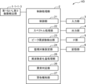
- FIG. 1 is a block diagram showing the configuration of the rolling bearing abnormality detection device according to the embodiment.
- FIG. 2 is a diagram for explaining mechanical equipment including rolling bearings.
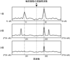
- FIG. 3 is a schematic diagram for explaining a method of specifying the setting peak frequency.
- the upper part of FIG. 3 shows the frequency spectrum in the frequency range of the theoretical frequency ft
- the upper part of FIG. 3 shows the frequency spectrum in the frequency range ft ⁇ dft to ft+dft with respect to the theoretical frequency ft
- the middle part of FIG. 3 shows the theoretical frequency ft 3 shows the frequency spectrum in the frequency range 2*ft ⁇ 2*dft to 2*ft+2*dft for twice the theoretical frequency ft
- FIG. 3 shows the frequency range 3*ft ⁇ 3*dft to 3* The frequency spectrum at ft+3*dft is shown.
- the horizontal axis of each figure is frequency, and their vertical axis is level (magnitude).
- FIG. 4 is a schematic diagram for explaining a method of specifying the setting peak frequency when using a plurality of vibration detection units.
- FIG. 4A shows a first case in which the setting peak frequency can be specified
- FIG. 4B shows a second case in which the setting peak frequency cannot be specified.
- FIG. 5A shows the frequency spectrum immediately after new installation or overhaul (frequency spectrum when the rolling bearing is healthy), and the frequency spectrum after one year from the case shown in FIG. later frequency spectrum).
- the upper, middle, and lower stages are the same as in FIG. 3, and the horizontal and vertical axes in each figure are also the same as in FIG. FIG.
- FIG. 6 is a schematic diagram for explaining the second method of setting the monitoring peak frequency.
- the horizontal axis of FIG. 6 is the elapsed time, and the vertical axis is the rate of change of the peak frequency.
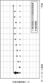
- FIG. 7 is a diagram for explaining a method of abnormality determination.
- the horizontal axis of FIG. 7 is the elapsed time, and the vertical axis is the change rate of the monitoring peak frequency.
- the rolling bearing abnormality detection device VD in the embodiment for example, as shown in FIG. , an interface unit (IF unit) 5 and a storage unit 6 .
- the vibration detection unit 1 is a device that is connected to the control processing unit 2 and detects vibrations generated in the rolling bearing as vibration data under the control of the control processing unit 2 .
- These first to third vibration detectors 1-1 to 1-3 are arranged in a device such as mechanical equipment having a rolling bearing, which is the target of abnormality detection.
- the mechanical equipment is an example of a device that has a rolling bearing, and may be any equipment that has a rolling bearing.
- the mechanical equipment M is a speed reducer M shown in FIG. , the first and second gears GA-1 and GA-2, the first to third rolling bearings BE-1 to BE-3, the first and second rotating shafts AX-1 and AX-2, and the first and a housing (not shown) that accommodates the second gears GA-1 and GA-2.
- the first rotating shaft AX-1 is fixed to the first gear GA-1, is the rotating shaft of the first gear GA-1, and is supported by the first rolling bearing BE-1.
- the second rotating shaft AX-2 is fixed to the second gear GA-2, is the rotating shaft of this second gear GA-1, and is supported by the second and third rolling bearings BE-2 and BE-3. .
- the first gear GA-1 and the second gear GA-2 mesh with each other. is transmitted to the second rotating shaft AX-2, and the second rotating shaft AX-2 rotates.
- the first to third vibration detectors 1-1 to 1-3 are arranged on the outer peripheries of the first to third rolling bearings BE-1 to BE-3, respectively. be done.
- the vibration detection unit 1 is not limited to the rolling bearing BE, and may be arranged, for example, in the housing.
- the vibration detector 1 (1-1 to 1-3) is arranged at the location where the vibration caused by the rolling bearing BE propagates.
- Such a vibration detection unit 1 (1-1 to 1-3) is, for example, an acceleration sensor, an AE (Acoustic Emission) sensor, or the like, and an appropriate sensor is used according to the frequency of the vibration to be detected.
- the vibration detection unit 1 (1-1 to 1-3) outputs the detection result to the control processing unit 2 as vibration data.
- the input unit 3 is connected to the control processing unit 2. For example, an operation mode command, a command to start specifying a monitoring peak frequency, a command to start abnormality detection (monitoring start), and various other commands are input. It is a device that inputs commands and various data necessary for operating the rolling bearing abnormality detection device VD, such as the name of mechanical equipment to be detected (monitored), to the rolling bearing abnormality detection device VD. , such as a plurality of input switches, a keyboard, a mouse, etc.
- the output unit 4 is a device that is connected to the control processing unit 2 and outputs commands and data input from the input unit 3, vibration data, etc., according to the control of the control processing unit 2. For example, a CRT display and a liquid crystal display. and a display device such as an organic EL display and a printing device such as a printer.
- a so-called touch panel may be configured from the input unit 3 and the output unit 4.
- the input unit 3 is a position input device for detecting and inputting an operation position, such as a resistive film method or a capacitive method
- the output unit 4 is a display device.
- the position input device is provided on the display surface of the display device, one or a plurality of input content candidates that can be input are displayed on the display device, and the input content that the user wants to input is displayed.
- the position is detected by the position input device, and the display content displayed at the detected position is input to the rolling bearing abnormality detection device VD as the user's operation input content.
- the IF unit 5 is a circuit that is connected to the control processing unit 2 and performs data input/output with an external device according to the control of the control processing unit 2.
- an interface circuit of RS-232C which is a serial communication method.
- an interface circuit using the Bluetooth (registered trademark) standard an interface circuit for infrared communication such as the IrDA (Infrared Data Association) standard
- an interface circuit using the USB (Universal Serial Bus) standard Universal Serial Bus
- the IF section 5 is a circuit for communicating with an external device, and may be, for example, a data communication card or a communication interface circuit conforming to the IEEE802.11 standard.
- the storage unit 6 is a circuit that is connected to the control processing unit 2 and stores various predetermined programs and various predetermined data according to the control of the control processing unit 2 .
- the various predetermined programs include, for example, a control processing program, and the control processing program controls each part 1, 3 to 6 of the rolling bearing abnormality detection device VD according to the function of each part.
- a program for obtaining the frequency spectrum of vibration data detected by the vibration detection unit 1 (1-1 to 1-3), and a frequency spectrum obtained by the spectrum processing program, a peak on the frequency spectrum when an abnormality occurs
- a peak frequency detection program that identifies as a peak frequency a frequency that exhibits a peak within a predetermined frequency range including the theoretical frequency that causes the peak detected by the reference frequency and the peak frequency detection program
- a frequency change amount processing program for obtaining the difference from the frequency as a time-dependent frequency change amount, an abnormality determination program for determining whether or not there is an abnormality in the rolling bearing based on the time-dependent frequency change amount obtained by the frequency change amount processing program,
- a warning notification program for notifying the warning to the outside by outputting a warning from the output unit 4 when the abnormality determination program determines that there is an abnormality in the rolling bearing, and in a monitoring peak frequency setting mode for setting the monitoring peak frequency and a monitoring target setting program for setting the setting peak frequency as the monitoring peak frequency when the setting peak frequency detected by the peak frequency detection program
- the various predetermined data include, for example, vibration data detected by the vibration detection unit 1 (1-1 to 1-3), theoretical frequency, peak frequency detected by the peak frequency detection program, the monitoring object Data necessary for executing each of these programs, such as the monitoring peak frequency set by the setting program, is included.
- a storage unit 6 includes, for example, a ROM (Read Only Memory) that is a non-volatile storage element and an EEPROM (Electrically Erasable Programmable Read Only Memory) that is a rewritable non-volatile storage element.
- the storage unit 6 includes a RAM (Random Access Memory) or the like that serves as a so-called working memory of the control processing unit 2 that stores data generated during execution of the predetermined program.
- the storage unit 6 may include a hard disk device capable of storing a large amount of data in order to store relatively large amount of learning data.
- the control processing unit 2 controls each unit 1, 3 to 6 of the rolling bearing abnormality detection device VD according to the function of each unit, and detects an abnormality of the rolling bearing (abnormality of the mechanical equipment equipped with the rolling bearing). circuit.
- the control processing unit 2 is configured with, for example, a CPU (Central Processing Unit) and its peripheral circuits.
- the control processing unit 2 includes a control unit 21, a spectrum processing unit 22, a peak frequency detection unit 23, a monitoring object setting unit 24, a frequency change amount processing unit 25, an abnormality determination unit 26 and a warning notification unit 27 are functionally configured.
- the control section 21 controls each section 1, 3 to 6 of the rolling bearing abnormality detection device VD according to the function of each section, and controls the entire rolling bearing abnormality detection device VD.
- the control unit 21 performs control according to the operation mode of the rolling bearing abnormality detection device VD.
- the rolling bearing abnormality detection device VD sets the monitoring peak frequency and then determines whether or not there is an abnormality in the rolling bearing.
- An abnormality monitoring mode for monitoring the rolling bearing (mechanical equipment including the rolling bearing) and a monitoring peak frequency setting mode for setting a peak frequency to be monitored in the abnormality monitoring mode as a monitoring peak frequency are provided.
- the control unit 21 stores the vibration data detected by the vibration detection unit 1 (1-1 to 1-3) in the storage unit 6 in association with the detection time.
- the control unit 21 acquires the detection result of the vibration detection unit 1 (1-1 to 1-3) at a predetermined sampling interval, and stores the acquired detection result in association with the detection time. Store in part 6. Since the detection result depends on the rotation speed of the speed reducer M, in this embodiment, an unillustrated tachometer (for example, a pulse generator (rotary encoder), etc.) for measuring the speed of the speed reducer M is used as the speed reducer. M, the control unit 21 acquires the output of the tachometer in synchronization with the detection result of the vibration detection unit 1 (1-1 to 1-3), and the acquired detection result and the output of the tachometer is stored in the storage unit 6 in association with the detection time.
- an unillustrated tachometer for example, a pulse generator (rotary encoder), etc.
- the detection result and the output of the tachometer are obtained at the sampling interval for a predetermined time (predetermined time length), at least after a predetermined period (first period). Do it twice.
- at least two detection results of the vibration detection unit 1 (1-1 to 1-3) that are associated with each detection time and are continuous in time series at sampling intervals are acquired as vibration data, and each detection is performed.
- At least two outputs of the tachometer that are associated with time and that are continuous in time series at sampling intervals are obtained as rotational speed data.
- the control unit 21 acquires the predetermined time length, the detection result of the vibration detection unit 1 (1-1 to 1-3) and the output of the tachometer at the sampling interval, and chronologically acquires the output of the tachometer at the sampling interval.
- Each continuous detection result and each output are stored in the storage unit 6 as vibration data and rotational speed data in association with the detection time.
- the first period is appropriately set to, for example, 3 months, 6 months, 12 months, or the like.
- the amount of temporal frequency change of the peak frequency with respect to the reference frequency (in this embodiment, the amount of temporal frequency change of the monitoring peak frequency with respect to the reference frequency described later in the abnormality monitoring mode) is observed.
- the detection result of the unit 1 (1-1 to 1-3) and the output of the tachometer are acquired in synchronization with each other at the sampling interval, and the obtained vibration detection unit 1 (1-1 to 1-3)
- the detection result, the output of the tachometer, and the detection time are associated with each other and stored in the storage unit 6 .
- each data stored in the storage unit 6 and stored in the storage unit 6 for a predetermined time for example, 1 day, 3 days, 1 week, etc.
- the detection result and each output are taken out as vibration data and rotation speed data, and used for abnormality determination.
- the vibration component caused by the change in the rotation speed of the speed reducer M may be extracted from the vibration data, and the rotation speed data may be generated from this extracted vibration component.
- the spectrum processing section 22 obtains the frequency spectrum of the vibration data detected by the vibration detection section 1 (1-1 to 1-3). More specifically, as preprocessing, the spectrum processing unit 22 removes (corrects) the influence of changes in the number of rotations from the vibration data based on the number of rotations data by a known conventional means, so that the speed reducer M is adjusted to a predetermined value. Vibration data when rotating at a constant number of revolutions is obtained, and the frequency spectrum of the vibration data is obtained by, for example, fast Fourier transforming the obtained vibration data. In the monitoring peak frequency setting mode, a frequency spectrum is obtained for each vibration data obtained by opening the first period. In the abnormality monitoring mode, vibration data is obtained at the timing of abnormality determination.
- the peak frequency detector 23 detects, from the frequency spectrum obtained by the spectrum processor 22, a frequency showing a peak within a predetermined frequency range including a theoretical frequency that causes a peak on the frequency spectrum when an abnormality occurs, as a peak frequency. be.
- the peak frequency detection unit 23 detects and specifies the peak frequency as a setting peak frequency in the monitoring peak frequency setting mode. That is, in the monitoring peak frequency setting mode, from the frequency spectrum obtained by the spectrum processing unit 22, a frequency showing a peak within a predetermined frequency range including a theoretical frequency that causes a peak on the frequency spectrum when an abnormality occurs is the setting peak. It is detected by the peak frequency detector 23 as a frequency.
- the peak frequency detection unit 23 further detects one or a plurality of frequencies showing a peak at a frequency that is an integral multiple of the setting peak frequency in the monitoring peak frequency setting mode. Detect and identify as peak frequency. For example, a double peak frequency showing a peak at double frequency and a triple peak frequency showing a peak at triple frequency are detected and identified.
- the integral multiple frequencies are not limited to these, and for example, 2, 3 and 4 times each frequency, 3 and 4 times each frequency, 2 and 4 times each frequency, and 3 and 4 times each frequency. It is appropriately set for each frequency of five times, and the like.
- the peak frequency detection unit 23 finally sets a frequency that can be set as the peak frequency to at least two of the plurality of vibration data detected by the plurality of vibration detection units 1 as the peak frequency. set to
- the theoretical frequency ft which causes a peak on the frequency spectrum when an abnormality occurs, is known and differs depending on the location of the rolling bearing damage (bearing damage), for example, as shown in Table 1 below.
- the bearing damage sites are, for example, the inner ring, the outer ring, the rolling elements and the cage.
- fti is the theoretical frequency when bearing damage occurs on the inner ring
- fto is the theoretical frequency when bearing damage occurs on the outer ring
- ftb is the theoretical frequency when bearing damage occurs on the rolling element.
- ftm is the theoretical frequency when bearing damage occurs in the cage.
- d is the diameter of the rolling element
- D is the pitch circle diameter of the rolling element
- Z is the number of rolling elements
- ⁇ is the contact angle.
- the frequency range for detecting the peak frequency (setting peak frequency in the monitoring peak frequency setting mode, monitoring peak frequency in the abnormality monitoring mode) with respect to the theoretical frequency ft (fti, fto, ftb, ftm) is , for example, ⁇ dft centered on the theoretical frequency ft, and are set as shown in Table 2 below for 1 to n times.
- the operator * is a multiplication operator.
- the frequency ranges for 1, 2, and 3 theoretical frequencies when bearing damage occurs at the outer ring are fto ⁇ dft to fto+dft, 2*fto ⁇ 2*dft to 2*fto+2*dft, and 3*fto-3*dft to 3*fto+3*dft.
- a peak that exists in common in the frequency spectrum in the frequency range for the theoretical frequency and the frequency spectrum in the frequency range for the integral multiple of the theoretical frequency is detected and specified by the peak frequency detector 23 as the setting peak frequency. For example, in one vibration detection unit 1, when each frequency spectrum shown in FIG.
- the peak frequency detector 23 sets the frequency f1.
- the setting peak A frequency and a peak frequency for integral multiple setting can be specified.
- the vibration generated in the rolling bearing BE is detected by the rotating shaft AX, the gear GA, and the housing. etc. are propagated and detected by the plurality of vibration detection units 1. Therefore, for at least two of the plurality of vibration data detected by the plurality of vibration detection units 1, the frequency spectrum in the frequency range with respect to the theoretical frequency and the theoretical frequency The frequency of a peak commonly present in the frequency spectrum in the frequency range corresponding to integral multiples of is detected and specified by the peak frequency detection unit 23 as the setting peak frequency. For example, when each frequency spectrum shown in FIGS.
- each frequency spectrum in the range ft ⁇ dft to ft+dft (each upper row), each frequency spectrum in each frequency range 2*ft ⁇ 2*dft to 2*ft+2*dft for twice the theoretical frequency ft (each middle row), and Since there is no peak in each frequency spectrum (each lower stage) in each frequency range 3*ft-3*dft to 3*ft+3*dft for three times each theoretical frequency ft, the peak frequency detection unit 23 detects the frequency f4 is finally detected as the setting peak frequency and not specified.
- the peak of the frequency f3 in the frequency spectrum (upper part) in the frequency range ft ⁇ dft to ft+dft with respect to the theoretical frequency ft is a frequency corresponding to twice the theoretical frequency ft.
- Each frequency spectrum in each frequency range ft-dft to ft+dft for each theoretical frequency ft (each upper row), each frequency spectrum in each frequency range 2*ft-2*dft to 2*ft+2*dft for twice each theoretical frequency ft (each middle row), and each frequency spectrum (each lower row) in each frequency range 3*ft ⁇ 3*dft to 3*ft+3*dft for three times each theoretical frequency ft.
- the detector 23 finally detects and specifies the frequency f3 as the setting peak frequency.
- the setting peak frequency is finally detected and specified, and the setting peak frequency and the integral multiple setting peak frequency can be specified.
- all three first to third vibration detection units 1-1 to 1-3 have common peaks, but as described above, at least two peaks are sufficient.
- the monitoring target setting unit 24 sets the setting peak frequency as the monitoring peak frequency to be monitored when the setting peak frequency detected and specified by the peak frequency detecting unit 23 changes with time. is to be set.
- the monitoring target setting unit 24 further determines that the one or more integral multiple setting peak frequencies detected and specified by the peak frequency detection unit 23 change with time in synchronism with the change with time of the setting peak frequency. When doing so, at least one of the one or more integral multiple setting peak frequencies is set as the monitoring peak frequency and added.
- the first setting peak frequency a [Hz] and the first integral multiple setting peak frequencies 2*a, 3*a [Hz] are detected and specified, one year later, the frequency shown in FIG.
- the peaks of the second setting peak frequency b [Hz] and the second integral multiple setting peak frequencies 2*b and 3*b [Hz] do not change over time, while the first setting peak frequency a [ Hz] and the peak frequencies 2*a and 3*a [Hz] for setting the first integer multiple are synchronized with each other and change over time by ⁇ c, 2* ⁇ c and 3* ⁇ c respectively.
- 24 sets the first setting peak frequency a [Hz] and the first integral multiple setting peak frequencies 2*a and 3*a [Hz] as monitoring peak frequencies.
- the monitoring peak frequency may be set with a single time-dependent change, but in this embodiment, the monitoring peak frequency is set with a plurality of time-dependent changes. That is, when the setting peak frequency detected and specified by the peak frequency detection unit 23 changes over time at a plurality of different points in time, the monitoring target setting unit 24 selects the setting peak frequency as the monitoring target. monitor peak frequency.
- the setting peak frequency detected and specified by the peak frequency detection unit 23 is detected for a predetermined period (second FIG. 6 shows the results of multiple observations for each period, follow-up observation period).
- second FIG. 6 shows the results of multiple observations for each period, follow-up observation period.
- the second The setting peak frequency b [Hz] ( ⁇ ) remains unchanged each time.
- the change in frequency may not only increase but also decrease or discontinuously increase and decrease.
- the monitoring target setting unit 24 sets the first setting peak frequency a [Hz], which changes over time a plurality of times and has a tendency to gradually change each time, as the monitoring peak frequency of the monitoring target,
- the monitoring target setting unit 24 does not set the second setting peak frequency b [Hz], which does not substantially change over time, as the monitoring peak frequency to be monitored.
- the peak frequency detection unit 23 detects the monitoring peak frequency set by the monitoring target setting unit 24 in the abnormality monitoring mode. That is, from the frequency spectrum obtained by the spectrum processing unit 22, the frequency that shows a peak within a predetermined frequency range including the theoretical frequency that causes a peak on the frequency spectrum when an abnormality occurs, and the frequency that is set by the monitoring target setting unit 24 is detected by the peak frequency detector 23 as the monitoring peak frequency.
- the frequency variation processing unit 25 obtains the difference between the peak frequency detected by the peak frequency detection unit 23 and a predetermined reference frequency preset as the peak frequency reference, as the frequency variation over time.
- a predetermined reference frequency preset as the peak frequency reference, as the frequency variation over time.
- the predetermined reference frequency is, for example, the monitoring peak frequency when the rolling bearing is healthy.
- the abnormality determination unit 26 determines whether there is an abnormality in the rolling bearing based on the temporal frequency change obtained by the frequency change amount processing unit 25 .
- the abnormality determination unit 26 determines whether there is an abnormality in the rolling bearing based on a predetermined threshold value based on the reference frequency (in the above example, the monitoring peak frequency when the rolling bearing is healthy). do. More specifically, the abnormality determination unit 26 obtains the rate of change in frequency with time based on the amount of change in frequency with time obtained by the frequency change amount processing unit 25, and compares the obtained rate of change in frequency with time with a predetermined threshold value. determines whether or not there is an abnormality in the rolling bearing.
- the threshold value may be appropriately set based on the reference frequency, but may be set to ⁇ 0.3 [%] or ⁇ 0.6 [%], for example, with the reference frequency f0 as the reference 0. be.
- the abnormality determining unit 26 determines that there is an abnormality when the amount of frequency change with time exceeds the threshold, and determines that there is no abnormality when the amount of frequency change with time does not exceed the threshold.
- the thresholds are a first threshold ⁇ Th1 (for example, ⁇ 0.6 [%], etc.) for determining the presence or absence of abnormality, and a second threshold ⁇ Th2 (for example, ⁇ 0.3 [%], etc.) (reference 0 ⁇
- ⁇ Th1 for example, ⁇ 0.6 [%], etc.
- ⁇ Th2 for example, ⁇ 0.3 [%], etc.
- the solid line represents the temporal frequency change rate Inn of the monitoring peak frequency applied to the inner ring
- the relatively short dashed line indicates the temporal frequency change rate Out of the monitoring peak frequency applied to the outer ring.
- the relatively long dashed line (---) is the rate of change in frequency with time Rol of the monitoring peak frequency applied to the rolling elements
- the dashed line is the rate of change in frequency with time Ret of the monitoring peak frequency applied to the cage.
- the warning notification unit 27 notifies the warning to the outside by outputting a warning from the output unit 4 when the abnormality determination unit 26 determines that there is an abnormality in the rolling bearing.
- the warning notification unit 27 since a sign of abnormality is also determined, the warning notification unit 27 not only outputs an abnormality warning from the output unit 4 when determining whether or not there is an abnormality and determines that there is an abnormality, but also outputs a sign of abnormality.
- the sign of abnormality is output from the output unit 4 .
- the rolling bearing abnormality detection device VD obtains the amount of change in frequency over time of the monitoring peak frequency with respect to the reference frequency at predetermined time intervals, such as one day or one week.
- the frequency change rate ⁇ f is compared with the first and second thresholds ⁇ Th1 and ⁇ Th2, respectively, and if abnormality is determined based on the comparison result, an abnormality warning is output from the output unit 4, and the comparison result is If it is determined that there is a sign of abnormality, the output unit 4 outputs a warning of a sign. Note that the process may be terminated without outputting no abnormality and no sign.
- the warning of the abnormality is performed, for example, by displaying a display color (for example, red display), voice output of a voice message (for example, "There is a problem with the rolling bearing"), and display of a text message (for example, "Danger").
- the warning of the sign is, for example, a display color different from that indicating an abnormality warning (e.g., yellow display), or a voice message different from an abnormality warning voice message (e.g., "There is a sign of abnormality in a rolling bearing", etc.). and display of a text message different from the text message (for example, "Warning” etc.) representing the warning of the abnormality.
- a display color different from that indicating an abnormality warning e.g., yellow display
- a voice message different from an abnormality warning voice message e.g., "There is a sign of abnormality in a rolling bearing", etc.
- display of a text message different from the text message for example, "Warning” etc.
- the control processing unit 2, the input unit 3, the output unit 4, the IF unit 5, and the storage unit 6 can be configured by, for example, a computer such as a desktop, notebook, or tablet computer.
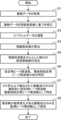
- FIG. 8 is a flow chart showing the operation of the rolling bearing abnormality detection device regarding the monitoring peak frequency setting mode.
- FIG. 9 is a flow chart showing the operation of the rolling bearing abnormality detection device regarding the abnormality monitoring mode.
- the control processing unit 2 When the rolling bearing abnormality detection device VD having such a configuration is powered on, it initializes each necessary part and starts its operation.
- the control processing unit 2 includes a control unit 21, a spectrum processing unit 22, a peak frequency detection unit 23, a monitoring target setting unit 24, a frequency change amount processing unit 25, an abnormality determination unit 26, and a warning notification unit.
- a unit 27 is functionally configured.
- the rolling bearing abnormality detection device VD in the embodiment determines whether or not there is an abnormality in the rolling bearing after setting the monitoring peak frequency. For this reason, first, the operation of the rolling bearing abnormality detection device VD regarding setting of the monitoring peak frequency in the monitoring peak frequency setting mode will be described. The operation of the rolling bearing abnormality detection device VD will be described.
- the rolling bearing abnormality detection device VD first causes the control unit 21 of the control processing unit 2 to perform detection of the vibration detection unit 1 (1-1 to 1-3) at predetermined sampling intervals for a predetermined time.
- the results and the output of the tachometer are acquired, and each detection result and each output that are continuous in time series at the sampling interval are stored in the storage unit 6 as vibration data and rotation speed data in association with the detection time (S1).
- the spectral processing unit 22 of the control processing unit 2 removes (corrects) the influence of the change in the rotation speed from the vibration data based on the rotation speed data, so that the speed reducer M Vibration data in the case of constant rotation at the number of revolutions is obtained and stored in the storage unit 6 (S2).
- the rolling bearing abnormality detection device VD uses the spectrum processing section 22 to obtain the frequency spectrum of the obtained vibration data, and stores it in the storage section 6 (S3).
- the rolling bearing abnormality detection device VD uses the peak frequency detection unit 23 of the control processing unit 2 to obtain the theoretical frequency ft that causes a peak on the frequency spectrum when an abnormality occurs, as shown in Table 1, and stores it in the storage unit 6. (S4).
- the theoretical frequency ft may be obtained in advance and stored in the storage unit 6, and used.
- the rolling bearing abnormality detection device VD uses the peak frequency detection unit 23 to determine the frequency range including the theoretical frequency ft for detecting the setting peak frequency and the integral multiple setting peak frequency, as shown in Table 2.
- a frequency range including integral multiples of the theoretical frequency ft for detection is obtained and stored in the storage unit 6 (S5). Note that each of these frequency ranges may be obtained in advance and stored in the storage unit 6, and used.
- the rolling bearing abnormality detection device VD tentatively specifies the setting peak frequency and the integral multiple setting peak frequency by the peak frequency detection unit 23 and the processing described above with reference to FIG. (S6).
- the rolling bearing abnormality detection device VD uses the peak frequency detection unit 23 to specify the final peak frequency for setting through the processing described above with reference to FIG. Store in the unit 6 (S7).
- the rolling bearing abnormality detection device VD sets the monitoring peak frequency by the monitoring target setting unit 24 of the control processing unit 2 through the processing described above with reference to FIG.
- the monitoring peak frequency set in the processing at the end of the monitoring peak frequency setting period is finally set as the monitoring peak frequency.
- the monitoring peak frequency is set and customized for the actual mechanical equipment equipped with rolling bearings.
- first and second thresholds Th1 and Th2 are set and stored by the operator (user).
- S11 to S14 shown in FIG. 9 are repeatedly executed, for example, at the start-up of 8-hour operation per day, or every half day or 1 day in continuous operation (24-hour operation).
- the machinery In the setting of the first and second thresholds Th1 and Th2, when the machinery is healthy, the machinery is rotated at a constant speed, the monitoring peak frequency is obtained, and the first and second thresholds ⁇ Th1 and ⁇ Th2 are set and stored. 6.
- the peak frequency for setting corresponding to the monitoring peak frequency set in this process S8 and the peak frequency for integral multiple setting stored in the storage unit 6 as a reference for temporal change The peak frequency in the healthy state may be set as the monitoring peak frequency f1.
- the rolling bearing abnormality detection device VD obtains the monitoring peak frequency by the control section 21, the spectrum processing section 22 and the peak frequency detection section 23 in the control processing section 2, and the frequency variation processing section 25 of the control processing section 2 (S11). More specifically, the control unit 21 obtains each vibration data based on each detection result of the first to third vibration detection units 1-1 to 1-3, and the spectrum processing unit 22 calculates each frequency of each vibration data. The spectrum is obtained, the peak frequency detection unit 23 searches each frequency spectrum for each peak corresponding to the monitoring peak frequency, and the frequency change amount processing unit 25 calculates, for example, 1 based on each frequency of these searched peaks. A time-dependent frequency change amount is obtained from the doubled monitoring peak frequency.
- the rolling bearing abnormality detection device VD causes the abnormality determination unit 26 of the control processing unit 2 to set the temporal frequency change rate ⁇ f based on the temporal frequency change obtained in the process S11 to the first or second threshold ⁇ Th1, ⁇ It is determined whether or not Th2 is exceeded.
- the rolling bearing abnormality detection device VD next executes the process S13, and terminates the present process.
- the rolling bearing abnormality detection device VD next executes the process S14 and terminates the present process.
- the rolling bearing abnormality detection device VD detects when the amount of frequency change with time exceeds the second threshold value ⁇ Th2 and does not exceed the first threshold value ⁇ Th1 (when the amount of frequency change with time exceeds the second threshold value +Th2 and does not exceed the first threshold value 1 threshold + Th1 or less, or when the amount of change in frequency over time is less than the second threshold - Th2 and is greater than or equal to the first threshold - Th1), it is determined to be a sign of abnormality, and the warning notification unit 27 of the control processing unit 2 , a warning of a sign is output from the output unit 4 and notified, and when the amount of frequency change over time exceeds the first threshold value ⁇ Th2 (when the amount of frequency change over time exceeds the first threshold value + Th2, or If the frequency change amount is less than the first threshold value -Th1), it is determined that there is an abnormality, and the warning notification unit 27 of the control processing unit 2 outputs an abnormality warning from the output unit 4 to notify.
- the rolling bearing abnormality detection device VD causes the warning notification section 27 to output from the output section 4 that there is no abnormality and no sign (within the allowable range).
- the rolling bearing (mechanical equipment having the rolling bearing) is monitored, the presence or absence of an abnormality sign and the presence or absence of the abnormality are determined, and the determination result is output.
- the rolling bearing abnormality detection device VD and the rolling bearing abnormality detection method mounted thereon determine the presence or absence of an abnormality in the rolling bearing based on the amount of change in frequency over time with respect to the peak frequency ( In the above-described embodiment, the presence or absence of an abnormality in the rolling bearing is determined based on the rate of change in frequency with time based on the amount of change in frequency with time with respect to the peak frequency). is not used, the abnormality of the rolling bearing can be properly detected. Then, the theoretical frequency that causes a peak on the frequency spectrum when an abnormality occurs can be logically calculated from a formula. Since the rolling bearing abnormality detection device VD and the rolling bearing abnormality detection method set the predetermined frequency range for detecting the peak frequency based on this logically calculable theoretical frequency, the predetermined frequency range is more appropriately determined. Frequency range can be set.
- the rolling bearing abnormality detection device VD and the rolling bearing abnormality detection method further include a warning notification unit 27, a warning regarding the presence of abnormality in the rolling bearing can be notified to the outside. By recognizing this externally notified warning, the user can recognize that there is an abnormality in the rolling bearing.
- the vibration of the rolling bearing there are actually multiple vibrations in the rolling bearing, such as gear engagement, its side bands, and multiple components (harmonic components) of shaft rotation.
- the frequency of vibration in rolling bearings changes over time due to wear and the like.
- the setting peak frequency when the setting peak frequency changes with time, the setting peak frequency is set as the monitoring peak frequency, so that the vibration of the rolling bearing can be detected appropriately.
- the rolling bearing abnormality detection device VD and the rolling bearing abnormality detection method at least one of one or a plurality of integral multiple setting peak frequencies showing a peak at a frequency that is an integral multiple of the setting peak frequency is set to the monitoring peak frequency. Since it is set and added, the vibration of rolling bearings can be detected more appropriately. Therefore, the rolling bearing abnormality detection device VD and the rolling bearing abnormality detection method can more appropriately determine the presence or absence of abnormality in the rolling bearing.
- the peak frequency that can be detected by at least two vibration detection units 1 is set as the monitoring peak frequency. It becomes easy to distinguish between the peak of the peak frequency and the noise, and the vibration of the rolling bearing can be detected appropriately.
- the rolling bearing abnormality detection device VD and the rolling bearing abnormality detection method set the peak frequency for setting as the monitoring peak frequency when the rolling bearing abnormality detection device VD and the rolling bearing abnormality detection method change over time at a plurality of different points in time. Since the case can be eliminated, the monitoring peak frequency of the monitoring target can be set more appropriately.
- a rolling bearing abnormality detection device includes a vibration detection unit that detects vibration generated in a rolling bearing as vibration data, a spectrum processing unit that obtains a frequency spectrum of the vibration data detected by the vibration detection unit, and the spectrum processing unit.
- a peak frequency detection unit that detects, as a peak frequency, a frequency that exhibits a peak within a predetermined frequency range including a theoretical frequency that causes a peak on the frequency spectrum when an abnormality occurs, from the frequency spectrum obtained in A, and a reference for the peak frequency in advance.
- a frequency change amount processing unit that obtains a difference between the set reference frequency and the peak frequency detected by the peak frequency detection unit as a frequency change amount with time; and an abnormality determination unit that determines whether or not there is an abnormality in the rolling bearing.
- the reference frequency is the peak frequency when the rolling bearing is healthy.
- Such a rolling bearing abnormality detection device determines whether or not there is an abnormality in the rolling bearing based on the amount of change in frequency with respect to the peak frequency over time, it uses various magnitudes of vibration depending on the structure of the device provided with the rolling bearing. Therefore, it is possible to properly detect the abnormality of the rolling bearing. Then, the theoretical frequency that causes a peak on the frequency spectrum when an abnormality occurs can be logically calculated from a formula. Since the rolling bearing abnormality detection device sets the predetermined frequency range for detecting the peak frequency based on this logically computable theoretical frequency, the predetermined frequency range can be set more appropriately.
- the above-described rolling bearing abnormality detection device further includes a warning notification section that notifies an external warning when the abnormality determination section determines that there is an abnormality in the rolling bearing.
- Such a bearing abnormality detection device further includes a warning notification unit, it is possible to externally notify a warning regarding the presence of abnormality in the rolling bearing. By recognizing this externally notified warning, the user can recognize that there is an abnormality in the rolling bearing.
- an abnormality monitoring mode for monitoring the rolling bearing by determining whether or not there is an abnormality in the rolling bearing; as a monitoring peak frequency, wherein the peak frequency detection unit detects the peak frequency as a setting peak frequency in the monitoring peak frequency setting mode, and detects the peak frequency as a setting peak frequency in the monitoring peak frequency setting mode.
- a monitoring target setting unit configured to set the setting peak frequency as the monitoring peak frequency when the setting peak frequency detected by the peak frequency detection unit changes over time; In the monitoring mode, the monitoring peak frequency set by the monitoring target setting unit is detected.
- the rolling bearing abnormality detection device sets the setting peak frequency as the monitoring peak frequency when the setting peak frequency changes with time, it is possible to appropriately detect the vibration of the rolling bearing.
- the peak frequency detection unit further includes one or more peaks showing peaks at frequencies that are integral multiples of the setting peak frequency in the monitoring peak frequency setting mode.
- the frequency is detected as one or a plurality of integral multiple setting peak frequencies
- the monitoring target setting unit further detects that the one or a plurality of integral multiple setting peak frequencies detected by the peak frequency detection unit is the setting peak frequency.
- At least one of the one or more integral multiple setting peak frequencies is set and added as the monitoring peak frequency when the frequency changes with time in synchronism with the change with time.
- At least one of one or a plurality of integral multiple setting peak frequencies showing a peak at a frequency that is an integral multiple of the setting peak frequency is set as the monitoring peak frequency. Therefore, the vibration of the rolling bearing can be detected more appropriately.
- the peak frequency detection unit detects at least two of the plurality of vibration data detected by the plurality of vibration detection units.
- a frequency that can be detected as the setting peak frequency is set as the monitoring peak frequency.
- the peak frequency that can be detected by at least two vibration detection units is set as the monitoring peak frequency. and can be easily distinguished, and the vibration of the rolling bearing can be detected appropriately.
- the monitoring target setting unit may change the peak frequency detected by the peak frequency detection unit a plurality of times at a plurality of different points in time.
- the setting peak frequency is set as the monitoring peak frequency.
- Such a rolling bearing abnormality detection device sets the peak frequency for setting as the monitoring peak frequency when there is a plurality of time-dependent changes at a plurality of different points in time. Therefore, the monitoring peak frequency of the monitoring target can be set more appropriately.
- a rolling bearing abnormality detection method includes a vibration detection step of detecting vibration generated in a rolling bearing as vibration data; a spectrum processing step of obtaining a frequency spectrum of the vibration data detected in the vibration detection step; A peak frequency detection step of detecting, as a peak frequency, a frequency showing a peak within a predetermined frequency range including a theoretical frequency that causes a peak on the frequency spectrum when an abnormality occurs, from the frequency spectrum obtained in the processing step, and a reference for the peak frequency.
- a frequency change amount processing step of obtaining the difference between a preset reference frequency and the peak frequency detected in the peak frequency detection step as the amount of change in frequency over time; and based on the amount of change in frequency over time obtained in the frequency change amount processing step and an abnormality determination step of determining whether or not there is an abnormality in the rolling bearing.
- the rolling bearing abnormality detection method determines whether or not there is an abnormality in the rolling bearing based on the amount of change in frequency with respect to the peak frequency over time, it uses various magnitudes of vibration depending on the structure of the device provided with the rolling bearing. Therefore, it is possible to properly detect the abnormality of the rolling bearing. Further, in the rolling bearing abnormality detection method, the predetermined frequency range for detecting the peak frequency is set based on the logically calculable theoretical frequency, so that the predetermined frequency range can be set more appropriately. .
- the present invention it is possible to provide a rolling bearing abnormality detection device and a rolling bearing abnormality detection method for detecting an abnormality occurring in a rolling bearing.
Landscapes
- Physics & Mathematics (AREA)
- General Physics & Mathematics (AREA)
- Acoustics & Sound (AREA)
- Testing Of Devices, Machine Parts, Or Other Structures Thereof (AREA)
- Measurement Of Mechanical Vibrations Or Ultrasonic Waves (AREA)
Abstract
Description


Claims (7)
- 転がり軸受で生じる振動を振動データとして検出する振動検出部と、
前記振動検出部で検出した振動データの周波数スペクトルを求めるスペクトル処理部と、
前記スペクトル処理部で求めた周波数スペクトルから、異常発生時に周波数スペクトル上にピークをもたらす理論周波数を含む所定の周波数範囲内でピークを示す周波数をピーク周波数として検出するピーク周波数検出部と、
前記ピーク周波数の基準として予め設定された基準周波数と前記ピーク周波数検出部で検出したピーク周波数との差分を経時周波数変化量として求める周波数変化量処理部と、
前記周波数変化量処理部で求めた経時周波数変化量に基づいて前記転がり軸受における異常の有無を判定する異常判定部とを備える、
転がり軸受異常検出装置。 - 前記異常判定部で前記転がり軸受の異常有りと判定した場合に、警告を外部に報知する警告報知部をさらに備える、
請求項1に記載の転がり軸受異常検出装置。 - 前記転がり軸受における異常の有無を判定することによって前記転がり軸受を監視する異常監視モードと、前記異常監視モードで監視する対象のピーク周波数を監視ピーク周波数として設定する監視ピーク周波数設定モードとを備え、
前記ピーク周波数検出部は、前記監視ピーク周波数設定モードにおいて、前記ピーク周波数を設定用ピーク周波数として検出し、
前記監視ピーク周波数設定モードにおいて、前記ピーク周波数検出部で検出した設定用ピーク周波数が経時変化した場合に、前記設定用ピーク周波数を前記監視ピーク周波数として設定する監視対象設定部をさらに備え、
前記ピーク周波数検出部は、前記異常監視モードにおいて、前記監視対象設定部で設定された監視ピーク周波数を検出する、
請求項1に記載の転がり軸受異常検出装置。 - 前記ピーク周波数検出部は、さらに、前記監視ピーク周波数設定モードにおいて、前記設定用ピーク周波数に対する整数倍の周波数でピークを示す1または複数の周波数を1または複数の整数倍設定用ピーク周波数として検出し、
前記監視対象設定部は、さらに、前記ピーク周波数検出部で検出した1または複数の整数倍設定用ピーク周波数が前記設定用ピーク周波数の経時変化と同期して経時変化する場合に、前記1または複数の整数倍設定用ピーク周波数のうちの少なくとも1つを前記監視ピーク周波数に設定して追加する、
請求項3に記載の転がり軸受異常検出装置。 - 前記振動検出部は、複数であり、
前記ピーク周波数検出部は、前記複数の振動検出部で検出した複数の振動データうちの少なくとも2個に対し、前記設定用ピーク周波数として検出できる周波数を前記監視ピーク周波数として最終的に設定する、
請求項3に記載の転がり軸受異常検出装置。 - 前記監視対象設定部は、前記ピーク周波数検出部で検出したピーク周波数が互いに異なる複数の時点で、複数回、経時変化した場合に、前記設定用ピーク周波数を前記監視ピーク周波数として設定する、
請求項3に記載の転がり軸受異常検出装置。 - 転がり軸受で生じる振動を振動データとして検出する振動検出工程と、
前記振動検出工程で検出した振動データの周波数スペクトルを求めるスペクトル処理工程と、
前記スペクトル処理工程で求めた周波数スペクトルから、異常発生時に周波数スペクトル上にピークをもたらす理論周波数を含む所定の周波数範囲内でピークを示す周波数をピーク周波数として検出するピーク周波数検出工程と、
前記ピーク周波数の基準として予め設定された基準周波数と前記ピーク周波数検出工程で検出したピーク周波数との差分を経時周波数変化量として求める周波数変化量処理工程と、
前記周波数変化量処理工程で求めた経時周波数変化量に基づいて前記転がり軸受における異常の有無を判定する異常判定工程とを備える、
転がり軸受異常検出方法。
Priority Applications (3)
| Application Number | Priority Date | Filing Date | Title |
|---|---|---|---|
| DE112022006262.2T DE112022006262T5 (de) | 2021-12-27 | 2022-10-24 | Wälzlagerabnormitätserfassungsvorrichtung und Wälzlagerabnormitätserfassungsverfahren |
| CN202280085272.9A CN118435034A (zh) | 2021-12-27 | 2022-10-24 | 滚动轴承异常检测装置以及滚动轴承异常检测方法 |
| US18/721,411 US20250060279A1 (en) | 2021-12-27 | 2022-10-24 | Rolling bearing abnormality detection device and rolling bearing abnormality detection method |
Applications Claiming Priority (2)
| Application Number | Priority Date | Filing Date | Title |
|---|---|---|---|
| JP2021212423A JP7592577B2 (ja) | 2021-12-27 | 2021-12-27 | 転がり軸受異常検出装置および転がり軸受異常検出方法 |
| JP2021-212423 | 2021-12-27 |
Publications (1)
| Publication Number | Publication Date |
|---|---|
| WO2023127248A1 true WO2023127248A1 (ja) | 2023-07-06 |
Family
ID=86998607
Family Applications (1)
| Application Number | Title | Priority Date | Filing Date |
|---|---|---|---|
| PCT/JP2022/039531 Ceased WO2023127248A1 (ja) | 2021-12-27 | 2022-10-24 | 転がり軸受異常検出装置および転がり軸受異常検出方法 |
Country Status (6)
| Country | Link |
|---|---|
| US (1) | US20250060279A1 (ja) |
| JP (1) | JP7592577B2 (ja) |
| CN (1) | CN118435034A (ja) |
| DE (1) | DE112022006262T5 (ja) |
| TW (1) | TWI842164B (ja) |
| WO (1) | WO2023127248A1 (ja) |
Citations (5)
| Publication number | Priority date | Publication date | Assignee | Title |
|---|---|---|---|---|
| JP2012026481A (ja) * | 2010-07-21 | 2012-02-09 | Hitachi Constr Mach Co Ltd | 軸受の損傷検出方法 |
| WO2016092845A1 (ja) * | 2014-12-10 | 2016-06-16 | 日本精工株式会社 | 異常診断装置、軸受、回転装置、産業機械及び車両 |
| JP2017101954A (ja) * | 2015-11-30 | 2017-06-08 | 日本精工株式会社 | 機械設備の評価方法 |
| WO2019171630A1 (ja) * | 2018-03-05 | 2019-09-12 | 日本電気株式会社 | 診断装置、システム、診断方法及びプログラム |
| JP2020159945A (ja) * | 2019-03-27 | 2020-10-01 | オークマ株式会社 | 転がり軸受の異常診断方法及び異常診断装置、異常診断プログラム |
Family Cites Families (3)
| Publication number | Priority date | Publication date | Assignee | Title |
|---|---|---|---|---|
| JP6536804B2 (ja) * | 2015-06-19 | 2019-07-03 | 日本電気株式会社 | 情報処理システム |
| WO2018158910A1 (ja) * | 2017-03-02 | 2018-09-07 | 株式会社日立製作所 | 診断装置および診断方法 |
| JP6918893B2 (ja) * | 2019-10-29 | 2021-08-11 | 株式会社川本製作所 | 異常検出装置 |
-
2021
- 2021-12-27 JP JP2021212423A patent/JP7592577B2/ja active Active
-
2022
- 2022-10-24 CN CN202280085272.9A patent/CN118435034A/zh active Pending
- 2022-10-24 WO PCT/JP2022/039531 patent/WO2023127248A1/ja not_active Ceased
- 2022-10-24 US US18/721,411 patent/US20250060279A1/en active Pending
- 2022-10-24 DE DE112022006262.2T patent/DE112022006262T5/de active Pending
- 2022-10-28 TW TW111141140A patent/TWI842164B/zh active
Patent Citations (5)
| Publication number | Priority date | Publication date | Assignee | Title |
|---|---|---|---|---|
| JP2012026481A (ja) * | 2010-07-21 | 2012-02-09 | Hitachi Constr Mach Co Ltd | 軸受の損傷検出方法 |
| WO2016092845A1 (ja) * | 2014-12-10 | 2016-06-16 | 日本精工株式会社 | 異常診断装置、軸受、回転装置、産業機械及び車両 |
| JP2017101954A (ja) * | 2015-11-30 | 2017-06-08 | 日本精工株式会社 | 機械設備の評価方法 |
| WO2019171630A1 (ja) * | 2018-03-05 | 2019-09-12 | 日本電気株式会社 | 診断装置、システム、診断方法及びプログラム |
| JP2020159945A (ja) * | 2019-03-27 | 2020-10-01 | オークマ株式会社 | 転がり軸受の異常診断方法及び異常診断装置、異常診断プログラム |
Also Published As
| Publication number | Publication date |
|---|---|
| JP2023096572A (ja) | 2023-07-07 |
| JP7592577B2 (ja) | 2024-12-02 |
| CN118435034A (zh) | 2024-08-02 |
| DE112022006262T5 (de) | 2024-10-10 |
| TWI842164B (zh) | 2024-05-11 |
| US20250060279A1 (en) | 2025-02-20 |
| TW202338315A (zh) | 2023-10-01 |
Similar Documents
| Publication | Publication Date | Title |
|---|---|---|
| EP3193155B1 (en) | Rotating machine abnormality detection device and method and rotating machine | |
| JP4874406B2 (ja) | 軸受の診断システム | |
| EP3842780A1 (en) | Method and device for diagnosing abnormality in rolling bearing | |
| US10739317B2 (en) | Method for monitoring and detecting the formation of degradation in at least one moving part of a rotating mechanism and associated system | |
| EP3929460B1 (en) | Anomaly detection system and anomaly detection method | |
| JPWO2020157818A1 (ja) | 診断装置及びこれを備えた設備並びに診断方法 | |
| JP6601376B2 (ja) | 回転体の検査装置、および、回転体の検査方法 | |
| EP3260838B1 (en) | Abnormality diagnosis system | |
| WO2023286414A1 (ja) | 転がり軸受異常検出装置および転がり軸受異常検出方法 | |
| JP7592577B2 (ja) | 転がり軸受異常検出装置および転がり軸受異常検出方法 | |
| JP2016170085A (ja) | 異常診断装置及び異常診断方法 | |
| JP6995969B1 (ja) | 回転機器の診断装置 | |
| CN117642617B (zh) | 滚动轴承异常检测装置以及滚动轴承异常检测方法 | |
| JP7518808B2 (ja) | 診断方法、診断プログラム、および診断装置 | |
| JP2018040594A (ja) | 回転軸装置及び回転軸装置における軸受の異常判定方法 | |
| US20260029026A1 (en) | Rolling-bearing monitoring method and device | |
| US20260029307A1 (en) | Rolling-bearing replacement-timing prediction method and rolling-bearing replacement-timing prediction device | |
| JP7476440B2 (ja) | 回転機械の衝撃系異常の診断方法 | |
| JP6946409B2 (ja) | 水処理設備の監視システム | |
| JP2024031072A (ja) | 監視装置、監視方法、及び監視プログラム | |
| JP2024039169A (ja) | 接触検出装置、接触検出方法及び回転機械の改修方法 |
Legal Events
| Date | Code | Title | Description |
|---|---|---|---|
| 121 | Ep: the epo has been informed by wipo that ep was designated in this application |
Ref document number: 22912796 Country of ref document: EP Kind code of ref document: A1 |
|
| WWE | Wipo information: entry into national phase |
Ref document number: 18721411 Country of ref document: US |
|
| WWE | Wipo information: entry into national phase |
Ref document number: 202280085272.9 Country of ref document: CN |
|
| WWE | Wipo information: entry into national phase |
Ref document number: 112022006262 Country of ref document: DE |
|
| 122 | Ep: pct application non-entry in european phase |
Ref document number: 22912796 Country of ref document: EP Kind code of ref document: A1 |