WO2023127078A1 - 操作装置及び操作システム - Google Patents
操作装置及び操作システム Download PDFInfo
- Publication number
- WO2023127078A1 WO2023127078A1 PCT/JP2021/048754 JP2021048754W WO2023127078A1 WO 2023127078 A1 WO2023127078 A1 WO 2023127078A1 JP 2021048754 W JP2021048754 W JP 2021048754W WO 2023127078 A1 WO2023127078 A1 WO 2023127078A1
- Authority
- WO
- WIPO (PCT)
- Prior art keywords
- section
- user
- finger
- operating device
- unit
- Prior art date
- Legal status (The legal status is an assumption and is not a legal conclusion. Google has not performed a legal analysis and makes no representation as to the accuracy of the status listed.)
- Ceased
Links
Images



Classifications
-
- G—PHYSICS
- G06—COMPUTING OR CALCULATING; COUNTING
- G06F—ELECTRIC DIGITAL DATA PROCESSING
- G06F3/00—Input arrangements for transferring data to be processed into a form capable of being handled by the computer; Output arrangements for transferring data from processing unit to output unit, e.g. interface arrangements
- G06F3/01—Input arrangements or combined input and output arrangements for interaction between user and computer
- G06F3/016—Input arrangements with force or tactile feedback as computer generated output to the user
-
- G—PHYSICS
- G06—COMPUTING OR CALCULATING; COUNTING
- G06F—ELECTRIC DIGITAL DATA PROCESSING
- G06F3/00—Input arrangements for transferring data to be processed into a form capable of being handled by the computer; Output arrangements for transferring data from processing unit to output unit, e.g. interface arrangements
- G06F3/01—Input arrangements or combined input and output arrangements for interaction between user and computer
- G06F3/011—Arrangements for interaction with the human body, e.g. for user immersion in virtual reality
- G06F3/014—Hand-worn input/output arrangements, e.g. data gloves
-
- G—PHYSICS
- G06—COMPUTING OR CALCULATING; COUNTING
- G06F—ELECTRIC DIGITAL DATA PROCESSING
- G06F3/00—Input arrangements for transferring data to be processed into a form capable of being handled by the computer; Output arrangements for transferring data from processing unit to output unit, e.g. interface arrangements
- G06F3/01—Input arrangements or combined input and output arrangements for interaction between user and computer
- G06F3/011—Arrangements for interaction with the human body, e.g. for user immersion in virtual reality
Definitions
- the present invention relates to an operating device and an operating system.
- a hand puppet manipulation system that includes a puppet manipulation device that is mounted in a hand puppet to operate the hand puppet and a control module that remotely controls the puppet manipulation device (see, for example, Patent Document 1).
- the control module includes a data glove that is used by being fitted to the user's hand to detect the movement of the user's hand.
- the data glove is equipped with multiple types of sensors that measure physical quantities that change according to the user's hand movements.
- the physical quantity data measured by the data glove is sent to the conversion module and converted into various control signals by the conversion module.
- the converted control signal is transmitted to the puppet manipulation device, and the puppet manipulation device operates the hand puppet based on the control signal.
- An operating device includes a mounting section that is mounted on a finger of a user, a first position detection section that is provided in the mounting section and detects the position of the finger, and a stimulus generator provided at a position corresponding to the finger of the user to apply an external stimulus to the user.
- An operation system includes the operation device according to the first aspect, and an operation target that operates based on operation information based on the detection result of the first position detection section.
- FIG. 1 is a schematic diagram showing a schematic configuration of an operation system according to a first embodiment
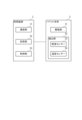
- FIG. FIG. 2 is a block diagram showing configurations of a puppet body and a control device according to the first embodiment
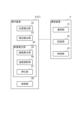
- FIG. 2 is a block diagram showing configurations of a communication device and an operation device according to the first embodiment
- FIG. 3 is a schematic diagram showing the positional relationship between a user's hand, a position/orientation detection unit, and a vibration generation unit according to the first embodiment
- the perspective view which shows typically the operating device with which the operating system which concerns on 2nd Embodiment is provided.
- FIG. 1 is a schematic diagram showing a schematic configuration of an operation system 1 according to this embodiment.
- An operation system 1 according to this embodiment includes a puppet body 2, a control device 3, a communication device 4, a magnetic field generator 5, and an operation device 6, as shown in FIG.
- the operation device 6 remotely operates the puppet body 2 attached to the puppet PP via the control device 3 and the communication device 4, and the stimulation detected by the puppet body 2 is detected by the operation device 6. It is what the user perceives.
- the puppet PP is a hollow puppet having a body PP1, a head PP2, a right arm PP3 and a left arm PP4, and is made of cloth, for example.
- the magnetic field generator 5 also generates a magnetic field detected by a position/orientation detector 62 of the operation device 6, which will be described later.
- the puppet body 2 is an operation target operated by the operation device 6 .
- the puppet body 2 is inserted inside the puppet PP to operate the puppet PP.
- the puppet body 2 can also be said to be an operation device that is operated by a user other than the user who uses the operation device 6 and that gives external stimulation to the user through the operation device 6 .
- the puppet body 2 includes a driving section 21 as shown in FIG.
- the drive unit 21 operates according to control signals input from the control device 3 .
- the drive unit 21 operates the head PP2, the right arm PP3, and the left arm PP4.
- the drive section 21 has a support section 211 , a head drive section 212 , a right arm drive section 213 and a left arm drive section 214 .
- the support portion 211 is provided corresponding to the trunk portion PP1, and supports the head driving portion 212, the right arm driving portion 213, and the left arm driving portion 214.
- the head driving section 212 bends or extends the head PP2.
- the right arm drive section 213 bends or extends the right arm section PP3.
- the left arm drive section 214 bends or extends the left arm section PP4.
- the driving units 212 to 214 can be exemplified by a configuration having a plurality of links configured to be mutually bendable and a motor for operating the plurality of links.
- FIG. 2 is a block diagram showing the configuration of the puppet body 2 and the control device 3.
- the puppet body 2 has a detection section 22 as shown in FIG.
- the detection unit 22 detects a stimulus acting on the puppet body 2 and outputs the detection result to the control device 3 .
- the detection unit 22 includes a tactile sensor 23 and a temperature sensor 24 .
- the tactile sensor 23 detects the approach of an object without contact. Also, the tactile sensor 23 detects the pressure applied to the contacting object. In other words, the tactile sensor 23 detects the pressure acting from the contacting object.
- the tactile sensors 23 are provided, for example, in the puppet body 2 at positions corresponding to the body PP1, the head PP2, the tip of the right arm PP3, and the tip of the left arm PP4.
- the tactile sensor 23 transmits the detection result to the control device 3 .
- the tactile sensor 23 has a function as a proximity sensor that detects the approach of an object and a function as a pressure sensor that detects pressure.
- the present invention is not limited to this, and the tactile sensor 23 may have one of a function as a proximity sensor and a function as a pressure sensor. At least one of a proximity sensor and a pressure sensor may be provided instead of the tactile sensor 23 .
- a temperature sensor 24 detects temperature.
- the temperature sensors 24 are provided, for example, at positions corresponding to the body PP1, head PP2, right arm PP3, and left arm PP4 in the puppet body 2, and transmit the detected temperatures to the control device 3.
- the control device 3 controls the operation of the puppet body 2 . Specifically, the control device 3 drives the drive unit 21 according to the operation information received from the communication device 4 to operate the puppet main body 2 and thus the puppet PP.
- the control device 3 includes a communication section 31, a storage section 32 and a control section 33, as shown in FIG.
- the communication unit 31 communicates with the puppet main body 2 and also communicates with the communication device 4 via the network NT. Under the control of the control unit 33 , the communication unit 31 outputs operation information received from the communication device 4 to the control unit 33 , and also outputs detection information indicating detection results by the detection unit 22 of the puppet body 2 to the communication device 4 .
- the communication unit 31 may be connected to the puppet main body 2 by wire, or may be connected by a communication method conforming to wireless communication standards such as Bluetooth (registered trademark) and IEEE 802.11.
- the storage unit 32 stores programs and data necessary for the operation of the control device 3.
- the storage unit 32 includes information on connection with the communication device 4, the type of the puppet body 2, and an operation program for operating the puppet body 2 based on the received operation information.
- the control unit 33 includes an arithmetic processing circuit such as a CPU (Central Processing Unit), and controls the operation of the puppet main body 2 according to a program stored in the storage unit 32. Specifically, the control unit 33 transmits a control signal for operating the drive unit 21 of the puppet body 2 based on the operation information received from the communication device 4 to the puppet body 2 via the communication unit 31 . Further, the control unit 33 transmits detection information indicating the detection result by the detection unit 22 of the puppet body 2 to the communication device 4 through the communication unit 31 .
- arithmetic processing circuit such as a CPU (Central Processing Unit)
- FIG. 3 is a block diagram showing the configuration of the communication device 4 and the operation device 6.
- the communication device 4 transmits to the control device 3 operation information corresponding to an operation signal input from the operation device 6 , and also based on detection information received from the control device 3 . to operate. That is, the communication device 4 is an operating device-side control device that controls part of the configuration of the operating device 6 .
- the communication device 4 has a communication section 41, a storage section 42, and a control section 43, as shown in FIG.
- the communication unit 41 not only communicates with the operation device 6, but also communicates with the control device 3 via the network NT. Under the control of the control unit 43, the communication unit 41 outputs detection information received from the control device 3 to the control unit 43, and also transmits operation information based on operation signals received from the operation device 6 to the control unit 3. .
- the communication unit 41 may be connected to the operation device 6 by wire, or may be connected by a communication method conforming to wireless communication standards such as Bluetooth (registered trademark) and IEEE 802.11.
- the storage unit 42 stores programs and data necessary for the operation of the communication device 4 .
- the storage unit 42 stores a conversion program for converting an operation signal received from the operation device 6 into operation information suitable for the control device 3 to operate the puppet body 2 .
- the storage unit 42 stores connection information for connecting with the control device 3 that controls the puppet body 2 that is the operation target of the operation device 6 . Therefore, when there are multiple sets of the control device 3 and the puppet main body 2 connected to the network NT, the storage unit 42 stores connection information for each control device 3 .
- the control unit 43 converts the operation signal received from the operation device 6 into the operation information based on the conversion program, and transmits the operation information to the control device 3 via the communication unit 41 . Further, the control unit 43 generates a control signal for operating the operation device 6 based on the detection information received from the control device 3 by the communication unit 41, transmits the generated control signal to the operation device 6, and controls the operation device. 6 controls part of the configuration.
- the operating device 6 remotely operates the puppet body 2 . Specifically, the operation device 6 detects the movement of the user, transmits an operation signal corresponding to the detected movement of the user to the communication device 4, and operates the puppet body 2 via the communication device 4 and the control device 3. Let In this embodiment, the operation device 6 detects the movement of the user's fingers (hand and fingers). In addition, the operation device 6 gives the user an external stimulus according to the control signal received from the communication device 4 based on the detection result of the detection unit 22 of the puppet body 2 .
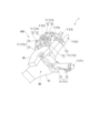
- FIG. 4 is a perspective view schematically showing the operating device 6.
- the operating device 6 includes a mounting portion 61 that is worn on one hand of the user.
- the wearing part 61 has a glove shape and is worn on one hand of the user. Therefore, the user can also wear a puppet similar to the puppet PP while wearing the operation device 6 on the hand so as to cover the outside of the operation device 6 .
- the mounting portion 61 be made of a stretchable material that can be brought into close contact with the user's hand.
- FIG. 5 is a schematic diagram showing the positional relationship between the user's hand, the position/orientation detection unit 62, and the vibration generation unit 65.
- the operating device 6 includes a position/orientation detection section 62, an approach detection section 63, a stimulus generation section 64, and a control section 68 as shown in FIG.
- the position/posture detection unit 62 is provided in the mounting unit 61 and detects the movement of the user's fingers. 4 and 5, the position/posture detection unit 62 includes a plurality of first position detection units 621 provided corresponding to each finger F, and a plurality of first position detection units 621 provided corresponding to positions other than the finger F on the user's hand. and a two-position detector 622 .
- the plurality of first position detectors 621 are provided on the mounting portion 61 at positions corresponding to the fingertips of each finger F and at positions on the nail side of each finger F. As shown in FIG. Specifically, as shown in FIG. 5, the first position detection unit 621 is provided for each finger F, and detects the position of the first position detection unit 621 as the position of the tip of the finger F to be detected. do.
- the plurality of first position detectors 621 includes first position detectors 6211-6215.
- the first position detection unit 6211 is provided for the first finger F1 (thumb)
- the first position detection unit 6212 is provided for the second finger F2 (index finger)
- the first position detection unit 6213 is provided for the third finger F3.
- the second position detection portion 622 is provided at a position corresponding to the back BH of the hand on the mounting portion 61, and detects the position of the second position detection portion 622 as the position of the back BH of the hand.
- each of the first position detection section 621 and the second position detection section 622 changes its resistance value depending on the strength and direction of the magnetic field generated outside the operation device 6 by the magnetic field generation device 5, which is a transmitter. It has a magnetic sensor. Then, each of the position detection units 621 and 622 calculates the position and orientation calculated based on the detection result of the magnetic sensor as the position and orientation of the corresponding finger and, by extension, the position and orientation of the finger.
- FIG. 6 is a schematic diagram showing the positional relationship between the user's hand and the proximity detector 63.
- the approach detection unit 63 is provided in the mounting unit 61 and detects the approach of an object to the user's fingers.
- the proximity detection unit 63 is configured by a proximity sensor provided on the outer surface of the mounting unit 61 at a position on the ventral side of the fingertip of each finger F, as shown in FIGS. 4 and 6 .
- the proximity detection unit 63 is provided in the mounting unit 61 at a position corresponding to the ventral portion of the fingertip of each finger F to be detected.
- the proximity detection unit 63 determines whether or not the object touches the finger when the user tries to grasp the object with the finger F of the hand wearing the operation device 6, that is, whether the hand wearing the operation device 6 has touched the object. Detect whether or not it is grabbed.
- the proximity sensors constituting the proximity detection unit 63 are provided for each of the fingers F1 to F5 of the user. It may also be provided on the palm PL and the back of the hand BH. Also, the above-described tactile sensor may be provided instead of the proximity sensor.
- the stimulus generating section 64 shown in FIG. 3 is provided in the mounting section 61 and operates based on a control signal received from the communication device 4 to apply an external stimulus to the user. That is, the stimulus generator 64 simulates the stimulus to the puppet PP based on the control signal based on the detection result of the detector 22 that detects the stimulus to the puppet body 2 .
- the stimulus generator 64 includes a vibration generator 65 , a temperature controller 66 and a presser 67 .
- the vibration generator 65 gives the user the illusion that an object is in contact with the user's fingers by applying vibration to the user.
- Each of the plurality of vibration generators 65 can employ a configuration including, for example, a voice coil motor.
- the vibration generating section 65 includes vibration generating sections 651 to 655 provided at positions corresponding to the respective fingers on the mounting section 61, as shown in FIGS.
- the vibration generating portion 651 is arranged at a position between the first joint of the first finger F1 and the joint at the base of the first finger F1 on the mounting portion 61 .
- the vibration generators 652 to 655 are provided at positions corresponding to the second finger F2, the third finger F3, the fourth finger F4 and the fifth finger F5 on the wearing part 61.
- FIG. More specifically, the vibration generators 652 to 655 are provided on the mounting portion 61 at corresponding positions between the first and second joints of the fingers F2 to F5.
- the user when vibration is applied directly to the fingertip, the user tends to have the illusion that an object touches the fingertip to which the vibration is applied.
- it is difficult to dispose the relatively large vibration generator 65 on the fingertip, and the operability of the operation device 6 deteriorates.
- the proximity detection section 63 and the temperature control section 66 are provided at the fingertip, it is difficult to secure a space for arranging the vibration generation section 65 at the fingertip.
- the vibration generator 651 is provided at a position between the first joint of the first finger F1 and the joint at the base of the first finger, and the vibration generators 652 to 655 are It is provided at a corresponding position between the first joint and the second joint of each of the second finger F2, the third finger F3, the fourth finger F4 and the fifth finger F5.
- the vibration generator 652 when vibration is generated by the vibration generator 652, the vibration is transmitted to the tip of the second finger F2, giving the user the illusion that vibration is directly applied to the tip of the second finger F2.
- the vibration generators 651 to 655 can be arranged at positions other than the fingertips, and the fingertips of the fingers F can be vibrated.
- the temperature control section 66 shown in FIG. 3 is provided at a position corresponding to the fingers of the wearing section 61, and gives the user a warm feeling and a cold feeling. Although detailed illustration is omitted, the temperature control units 66 are provided, for example, at the positions corresponding to the fingertips of the fingers F, the palm PL, and the back of the hand BH in the wearing unit 61, respectively. there is The temperature control section 66 is provided inside the mounting section 61 .
- the temperature control unit 66 can be composed of a thermoelectric conversion element such as a Peltier element, for example.
- the pressing portion 67 is provided at a position corresponding to the finger of the mounting portion 61 and presses the user's finger. Although illustration is omitted, the pressing portion 67 is provided at a position corresponding to each finger F, a position corresponding to the palm PL, and a position corresponding to the back of the hand BH on the mounting portion 61 . Specifically, among the plurality of pressing portions 67, five pressing portions 67 provided corresponding to each finger F are provided at positions corresponding to the tip of the finger F to be pressed, and press the tip of the finger F. . A plurality of pressing portions 67 may be provided at a position corresponding to the palm PL and a position corresponding to the back of the hand BH on the mounting portion 61 . As the pressing portion 67, a combination of an air pump and a silicon air chamber that expands or contracts by gas supplied from the air pump can be exemplified. Combinations can be exemplified.
- the control section 68 controls the operation of the operating device 6 .
- the control unit 68 is electrically connected to the position/orientation detection unit 62 , the proximity detection unit 63 and the stimulus generation unit 64 .
- the control unit 68 transmits to the communication device 4 an operation signal indicating the position and posture of the finger detected by the position/orientation detection unit 62 , and also transmits a detection signal indicating the result of detection by the proximity detection unit 63 to the communication device 4 .
- the control unit 68 operates the vibration generating unit 65 , the temperature adjusting unit 66 and the pressing unit 67 of the stimulation generating unit 64 based on the control signal received from the communication device 4 .
- the control section 68 is provided in the mounting section 61 at a position corresponding to the user's wrist.
- the operation system 1 includes an operation device 6 and a puppet body 2 that operates based on operation information based on the detection result of the first position detection section 621 of the operation device 6 .
- the puppet body 2 corresponds to an operation target.
- the operating device 6 includes a mounting section 61 , a first position detection section 621 and a stimulus generation section 64 .
- the wearing part 61 is worn on a user's finger.
- the first position detection section 621 is provided in the mounting section 61 and detects the position of the corresponding finger F.
- the stimulus generating section 64 is provided at a position corresponding to the user's finger F on the mounting section 61, and applies an external stimulus to the user.
- the position of the finger F of the user wearing the operating device 6 and the posture of the finger F can be detected by the first position detection section 621 .
- the stimulus generator 64 can apply an external stimulus to the finger F of the user. Therefore, according to the position and posture of the finger F detected by the first position detection unit 621, the finger F to be detected by the first position detection unit 621 or another finger F can be given an external stimulus. Therefore, the versatility of the operating device 6 can be enhanced.
- the operation system 1 that can operate an operation target (for example, the puppet main body 2) using the operation device 6 and provide feedback to the user of stimuli given to the operation target from the outside.
- the first position detection section 621 is provided on the user's fingernail side of the mounting section 61 . According to such a configuration, it is not necessary to provide the first position detection section 621 at the tip of the finger F, which is the detection target of the first position detection section 621 . Therefore, compared to the case where the first position detection unit 621 is provided according to the fingertip of the finger F that is the target of position detection, the degree of freedom of the fingertip that is the target of position detection can be increased.
- the stimulus generator 64 includes a vibration generator 65 .
- Vibration generators 652 to 655 of the vibration generators 65 are provided between the first and second joints of the corresponding fingers on the mounting part 61 and generate vibrations. According to such a configuration, when vibration is generated by the vibration generating units 652 to 655 arranged at the above positions, the vibration can be transmitted to the fingertip of the corresponding finger F, and when the fingertip is directly vibrated, It can give users the same illusion as Accordingly, since it is not necessary to provide the vibration generating section 65 on the fingertip, the degree of freedom of the fingertip can be increased compared to the case where the vibration generating section 65 is provided on the fingertip.
- the operating device 6 includes an approach detection section 63 that is provided on the pad side of the user's fingertip in the mounting section 61 and detects the approach of an object.
- the approach detection unit 63 can accurately detect the approach of an object to the user's fingertip.
- the stimulus generator 64 includes a temperature controller 66 capable of adjusting temperature. According to such a configuration, it is possible to give the user a cool feeling and a warm feeling. Therefore, the versatility of the operation device 6 can be enhanced, and the contact of another user or an object with respect to the operation target can be perceived by the user operating the operation device 6 by the temperature.
- the stimulation generating section 64 includes a pressing section 67 that presses fingers.
- the pressing portion 67 can give a reaction force when the user grips an object, or a tactile sensation as if another person touched the user's hand. Therefore, the versatility of the operating device 6 can be enhanced.
- the operating device 6 includes a second position detection section 622 provided at a position corresponding to the back BH of the user's hand in the mounting section 61 and detecting the position of the back BH of the hand. According to such a configuration, the motion of turning the user's wrist can be detected by the second position detection section 622 . Therefore, the movement of the user's hand can be detected in detail.
- the mounting portion 61 is shaped like a glove that covers the fingers of the user. According to such a configuration, it is possible to make it easier for the user to wear the operating device 6 on the hand.
- the first position detection section 621 has a magnetic sensor that detects an externally generated magnetic field.
- the second position detector 622 is also the same. According to such a configuration, for example, compared to a configuration in which the first position detection unit 621 includes an exoskeleton attached to the finger F and a movement amount detection device that detects the movement amount of the exoskeleton, The position of the finger F can be detected without disturbing the movement of the finger F.
- the operation device 6 is provided at a position corresponding to the user's wrist on the mounting section 61 and includes a control section 68 that controls the stimulus generation section 64 .
- the control section 68 can be arranged at a position where the movement of the hand is less likely to be hindered. Therefore, it is possible to suppress a decrease in the degree of freedom of the user's fingers.
- the operating system according to this embodiment has the same configuration as the operating system 1 according to the first embodiment, but differs in the configuration of the operating device.
- parts that are the same as or substantially the same as those already described are denoted by the same reference numerals, and descriptions thereof are omitted.
- FIG. 7 is a schematic diagram showing the operating device 7 included in the operating system according to this embodiment.
- the operation system according to the present embodiment has the same configuration and functions as the operation system 1 according to the first embodiment, except that it includes an operation device 7 shown in FIG. 7 instead of the operation device 6 according to the first embodiment.
- the operation system according to the present embodiment includes a puppet body 2 arranged inside the puppet PP, a control device 3, a communication device 4, and an operation device 7.
- the operating device 7 communicates with the communication device 4 to remotely operate the puppet main body 2 shown in the first embodiment.
- the operation device 7 detects the movement of the user's fingers, transmits an operation signal corresponding to the detected movement of the fingers to the communication device 4, and also provides an external stimulus to the user according to the control signal received from the communication device 4.
- the operation device 7 has the same configuration and functions as the operation device 6 except that a stimulus generator 64A is provided instead of the stimulus generator 64 . That is, the operating device 7 includes a mounting section 61 , a position/orientation detection section 62 , an approach detection section 63 , a stimulus generation section 64A, and a control section 68 .
- a stimulus generator 64A is provided instead of the stimulus generator 64 .
- control unit 68 is provided at a position corresponding to the back of the hand BH on the mounting unit 61 .
- the control section 68 may be provided at a position corresponding to the user's wrist, like the control section 68 in the operating device 6 according to the first embodiment.
- the stimulus generator 64A includes a vibration generator 65, a temperature controller 66, and a presser 67, as well as a reaction force generator 71, like the stimulus generator 64 according to the first embodiment.
- the reaction force generator 71 generates a reaction force against the movement of the user's fingers, and gives the user the feeling that the fingers are touching an object.
- the reaction force generation unit 71 generates a reaction force that restricts the movement of the user's finger F, and gives the user the feeling that the finger F is touching an object.
- the reaction force generator 71 includes a reaction force generator 711 that applies a reaction force to the first finger F1, a reaction force generator 712 that applies a reaction force to the second finger F2, and a reaction force generator that applies a reaction force to the third finger F3. It includes a force generator 713, a reaction force generator 714 that applies a reaction force to the fourth finger F4, and a reaction force generator 715 that applies a reaction force to the fifth finger F5.
- Each of the reaction force generators 711 to 715 has a link mechanism 72 and a resistance section 73 .
- the link mechanism 72 connects the finger F to which the reaction force is applied and the resistance portion 73 .
- the link mechanism 72 is configured with a plurality of links that are bendably connected to each other, and is displaced according to the movement of the connected finger F. As shown in FIG. One end of the link mechanism 72 is connected to the tip of the finger F on which the reaction force is applied, and the other end of the link mechanism 72 is connected to the resistance section 73 .
- the operating device 7 is a so-called exoskeleton controller.
- the resistance unit 73 changes the resistance against the displacement of the link mechanism 72, which is displaced according to the movement of the finger F to which the reaction force is applied, so that the reaction force against the movement of the finger F is applied to the finger F.
- the resistance portion 73 of the reaction force generating portion 712 increases resistance to displacement of the link mechanism 72 that is displaced according to the bending motion of the second finger F2 when the second finger F2 bends. It is made difficult to bend the finger F2. As a result, since a reaction force to the bending motion of the second finger F2 acts on the second finger F2, the user can perceive the illusion that an object is in contact with the second finger F2.
- a displacement detector such as a potentiometer for detecting the displacement of the link mechanism 72 is provided. It may be configured as a first position detection section that detects the position of F.
- the present invention is not limited to the above-described embodiments, and includes modifications, improvements, and the like within the scope of achieving the object of the present invention.
- the position/orientation detection section 62 including the first position detection section 621 and the second position detection section 622 has a magnetic sensor that detects magnetism.
- the detection method for detecting the position and orientation of the finger by the position/orientation detection unit is not limited to this, and may be another method.
- the position/orientation detection section 62 includes the first position detection section 621 (6211 to 6215) provided in the mounting section 61 at a position corresponding to the fingertip of the finger F to be detected, and the position detection section 621 corresponding to the back of the hand BH. and a second position detector 622 provided at a position.
- the present invention is not limited to this, and the position/orientation detection section 62 may include at least one first position detection section among the first position detection sections 6211 to 6215.
- the second position detection section 622 may It can be omitted.
- the first position detection unit 621 is provided in the mounting unit 61 so as to correspond to the position on the nail side of the fingertip of the finger F that is the object of detection.
- the first position detection section may be provided anywhere.
- the vibration generators 652 to 655 provided for the second finger F2, the third finger F3, the fourth finger F4, and the fifth finger F5 correspond to the first joint of each finger F in the mounting portion 61. It is assumed that it is provided between the second joint.
- the present invention is not limited to this, and the positions where the vibration generators 652 to 655 are provided may be other positions, and the vibration generator 65 may be omitted.
- the operating devices 6 and 7 are provided with the proximity detection section 63 provided in the mounting section 61 on the abdomen side of the user's fingertip.
- the present invention is not limited to this, and the approach detection unit 63 may be omitted.
- the position of the proximity detection part 63 does not have to be the position on the pad side of the fingertip in the mounting part 61, and can be changed as appropriate.
- the stimulus generator 64 includes the temperature controller 66 . That is, the operating devices 6 and 7 are provided with a temperature control section 66 capable of controlling the temperature.
- the present invention is not limited to this, and the temperature control section 66 may be omitted.
- the position of the temperature control unit 66 is not limited to the above, and may be other positions.
- the stimulus generating section 64 includes the pressing section 67 .
- the operating devices 6 and 7 are provided with a pressing portion 67 for pressing the fingers of the user.
- the present invention is not limited to this, and the pressing portion 67 may be omitted.
- the position of the pressing portion 67 is not limited to the above, and may be another position.
- the operating devices 6 and 7 are provided in the mounting section 61 at a position corresponding to the back BH of the user's hand, and include the second position detection section 622 that detects the position of the back BH of the hand.
- the present invention is not limited to this, and the second position detection section 622 may be omitted.
- the wearing part 61 is shaped like a glove that covers the user's fingers.
- the shape of the mounting portion 61 is not limited to this, and can be changed as appropriate as long as each component of the operating devices 6 and 7 can be arranged.
- the mounting portion 61 may be band-shaped, or may have the same shape as the puppet PP.
- the operating device 6 is provided at a position corresponding to the user's wrist on the wearing section 61 and includes the control section 68 that controls the stimulus generating section 64 .
- the control unit 68 may be omitted if, for example, the configuration of the operation devices 6 and 7 such as the position/orientation detection unit 62 and the stimulus generation unit 64 are directly connected to the communication device 4 .
- the control unit 68 may be provided at a position corresponding to the back of the hand on the mounting part 61, or may be provided at another position. good too. That is, the position of the control unit 68 can be changed as appropriate, and may be a position other than the finger of the user.
- the operation devices 6 and 7 configure an operation system together with an operation target (for example, the puppet main body 2) that operates based on operation information based on the detection result of the position/orientation detection unit 62.
- the operation target of the operation devices 6 and 7 may not be the puppet main body 2, and may be another configuration.
- Such manipulation targets may be, for example, robot hands and manipulators.
- the operation devices 6 and 7 operate the puppet main body 2 via the control device 3 and the communication device 4 communicating via the network NT.
- the operation devices 6 and 7 are not limited to this, and may directly operate the puppet body 2 that is the operation target.
- the operation device includes a mounting section that is mounted on a user's finger, a first position detection section that is provided in the mounting section and detects the position of the finger, and a a stimulus generator provided at a location for applying an external stimulus to the user.
- the position of the finger of the user wearing the operating device and the posture of the finger can be detected by the first position detection section.
- the stimulus generator can apply an external stimulus to the user's finger. Therefore, an external stimulus can be applied to the finger whose position is to be detected by the first position detection unit or to another finger according to the position and orientation of the finger detected by the first position detection unit. Therefore, the versatility of the operating device can be enhanced.
- the first position detection section may be provided on the user's fingernail side of the mounting section. According to such a configuration, it is not necessary to provide the first position detection section at the fingertip of the finger whose position is to be detected by the first position detection section. Therefore, compared with the case where the first position detection unit is provided according to the fingertip of the finger that is the target of position detection, the degree of freedom of the fingertip that is the target of position detection can be increased.
- the stimulus generator is provided between the user's first and second finger joints in the attachment section, and generates vibration.
- a vibration generator may be included. According to such a configuration, when vibration is generated by the vibration generating section arranged at the above position, the vibration can be transmitted to the fingertip, giving the user the same illusion as when the fingertip is directly vibrated. can. Accordingly, since it is not necessary to provide the vibration generating section at the fingertip, the degree of freedom of the fingertip can be increased compared to the case where the vibration generating section is provided at the fingertip.
- the operating device according to any one of [1] to [3], further comprising an approach detection section provided on the pad side of the fingertip of the user in the attachment section and detecting approach of an object. good too.
- the proximity detection section since the proximity detection section that detects the proximity of an object is provided on the ventral side of the fingertip, the proximity detection section can accurately detect the proximity of the object to the user's fingertip.
- the stimulation generating section may include a temperature control section capable of controlling temperature. According to such a configuration, it is possible to give the user a cool feeling and a warm feeling. Therefore, the versatility of the operating device can be enhanced, and the contact of another user or an object to the operation target operated by the operating device can be perceived by the user operating the operating device by the temperature.
- the stimulus generating section may include a pressing section that presses the fingers.
- the pressing portion can impart a reaction force when the user grips an object, or a tactile sensation as if another person touched the user's hand. Therefore, the versatility of the operating device can be enhanced.
- a second position detection section provided at a position corresponding to the back of the hand of the user in the mounting section and detecting the position of the back of the hand.
- the motion of turning the user's wrist can be detected by the second position detection section. Therefore, the movement of the user's hand can be detected in detail.
- the attachment section may be shaped like a glove that covers the fingers of the user. According to such a configuration, it is possible to make it easier for the user to wear the operating device on the hand.
- the first position detection section may have a magnetic sensor that detects an externally generated magnetic field.
- the first position detection unit includes an exoskeleton attached to the finger and a movement amount detection device that detects the movement amount of the exoskeleton, the position of the finger is reduced. Finger position can be detected without hindering movement.
- the operation device according to any one of [1] to [9], further comprising a control unit provided at a position corresponding to the wrist of the user in the wearing unit and controlling the stimulus generation unit.
- the control section can be arranged at a position where the movement of the hand is less likely to be hindered. Therefore, it is possible to suppress a decrease in the degree of freedom of the user's fingers.
- An operation system includes the operation device according to any one of [1] to [10], and an operation target that operates based on operation information based on the detection result of the first position detection unit. . According to such a configuration, it is possible to obtain the same effects as those of the operating device described above. Accordingly, it is possible to configure an operation system capable of performing the operation of the operation target by the operation device and the feedback to the user of the stimulus given to the operation target from the outside.
Landscapes
- Engineering & Computer Science (AREA)
- General Engineering & Computer Science (AREA)
- Theoretical Computer Science (AREA)
- Human Computer Interaction (AREA)
- Physics & Mathematics (AREA)
- General Physics & Mathematics (AREA)
- User Interface Of Digital Computer (AREA)
- Mechanical Control Devices (AREA)
- Position Input By Displaying (AREA)
Priority Applications (4)
| Application Number | Priority Date | Filing Date | Title |
|---|---|---|---|
| PCT/JP2021/048754 WO2023127078A1 (ja) | 2021-12-28 | 2021-12-28 | 操作装置及び操作システム |
| JP2023570560A JPWO2023127078A1 (https=) | 2021-12-28 | 2021-12-28 | |
| EP21969960.0A EP4459425A4 (en) | 2021-12-28 | 2021-12-28 | ACTUATING DEVICE AND ACTUATING SYSTEM |
| US18/718,638 US20250044872A1 (en) | 2021-12-28 | 2021-12-28 | Operation device and operation system |
Applications Claiming Priority (1)
| Application Number | Priority Date | Filing Date | Title |
|---|---|---|---|
| PCT/JP2021/048754 WO2023127078A1 (ja) | 2021-12-28 | 2021-12-28 | 操作装置及び操作システム |
Publications (1)
| Publication Number | Publication Date |
|---|---|
| WO2023127078A1 true WO2023127078A1 (ja) | 2023-07-06 |
Family
ID=86998386
Family Applications (1)
| Application Number | Title | Priority Date | Filing Date |
|---|---|---|---|
| PCT/JP2021/048754 Ceased WO2023127078A1 (ja) | 2021-12-28 | 2021-12-28 | 操作装置及び操作システム |
Country Status (4)
| Country | Link |
|---|---|
| US (1) | US20250044872A1 (https=) |
| EP (1) | EP4459425A4 (https=) |
| JP (1) | JPWO2023127078A1 (https=) |
| WO (1) | WO2023127078A1 (https=) |
Cited By (1)
| Publication number | Priority date | Publication date | Assignee | Title |
|---|---|---|---|---|
| JP7855295B1 (ja) | 2026-03-19 | 2026-05-08 | Diver-X株式会社 | グローブ型デバイス |
Families Citing this family (1)
| Publication number | Priority date | Publication date | Assignee | Title |
|---|---|---|---|---|
| EP4535334A4 (en) * | 2022-06-02 | 2025-04-23 | Sony Group Corporation | INFORMATION PROCESSING DEVICE, INFORMATION PROCESSING METHOD AND INFORMATION PROCESSING PROGRAM |
Citations (6)
| Publication number | Priority date | Publication date | Assignee | Title |
|---|---|---|---|---|
| JP2000338858A (ja) * | 1999-05-28 | 2000-12-08 | Toshiba Corp | 仮想空間体感装置 |
| JP2003337962A (ja) * | 2002-05-17 | 2003-11-28 | Seiko Epson Corp | 画像処理装置および画像処理方法、ならびに、画像処理プログラムおよびその記録媒体 |
| JP2004029999A (ja) * | 2002-06-24 | 2004-01-29 | Matsushita Electric Ind Co Ltd | 力触覚ディスプレイハンドおよびその製造方法 |
| JP2010089248A (ja) | 2008-10-09 | 2010-04-22 | National Chiao Tung Univ | ハンドパペットマニピュレーションシステム |
| JP2018512643A (ja) * | 2015-02-20 | 2018-05-17 | 株式会社ソニー・インタラクティブエンタテインメント | 周辺デバイスを伴うグローブの指先の磁気追跡 |
| JP2021149890A (ja) * | 2020-03-24 | 2021-09-27 | 株式会社エヌアンドエヌ | 情報伝達装置及び情報伝達システム |
Family Cites Families (7)
| Publication number | Priority date | Publication date | Assignee | Title |
|---|---|---|---|---|
| JP2000501033A (ja) * | 1995-11-30 | 2000-02-02 | ヴァーチャル テクノロジーズ インコーポレイテッド | 触覚をフィードバックする人間/機械インターフェース |
| JP2004213350A (ja) * | 2002-12-27 | 2004-07-29 | Seiko Epson Corp | 力覚提示装置及び画像補正方法 |
| US20170119553A1 (en) * | 2014-06-20 | 2017-05-04 | Scuola Superiore S.Anna | A haptic feedback device |
| CN204044747U (zh) * | 2014-08-20 | 2014-12-24 | 博世(中国)投资有限公司 | 用于采集手语识别用数据的手套 |
| US11474605B2 (en) * | 2016-11-17 | 2022-10-18 | Sony Corporation | Vibration presentation device and vibration presentation method |
| US20180335842A1 (en) * | 2017-05-19 | 2018-11-22 | Axonvr Corporation | Haptic feedback glove |
| KR102414497B1 (ko) * | 2017-09-29 | 2022-06-29 | 애플 인크. | Imu 기반 장갑 |
-
2021
- 2021-12-28 JP JP2023570560A patent/JPWO2023127078A1/ja active Pending
- 2021-12-28 US US18/718,638 patent/US20250044872A1/en active Pending
- 2021-12-28 EP EP21969960.0A patent/EP4459425A4/en active Pending
- 2021-12-28 WO PCT/JP2021/048754 patent/WO2023127078A1/ja not_active Ceased
Patent Citations (6)
| Publication number | Priority date | Publication date | Assignee | Title |
|---|---|---|---|---|
| JP2000338858A (ja) * | 1999-05-28 | 2000-12-08 | Toshiba Corp | 仮想空間体感装置 |
| JP2003337962A (ja) * | 2002-05-17 | 2003-11-28 | Seiko Epson Corp | 画像処理装置および画像処理方法、ならびに、画像処理プログラムおよびその記録媒体 |
| JP2004029999A (ja) * | 2002-06-24 | 2004-01-29 | Matsushita Electric Ind Co Ltd | 力触覚ディスプレイハンドおよびその製造方法 |
| JP2010089248A (ja) | 2008-10-09 | 2010-04-22 | National Chiao Tung Univ | ハンドパペットマニピュレーションシステム |
| JP2018512643A (ja) * | 2015-02-20 | 2018-05-17 | 株式会社ソニー・インタラクティブエンタテインメント | 周辺デバイスを伴うグローブの指先の磁気追跡 |
| JP2021149890A (ja) * | 2020-03-24 | 2021-09-27 | 株式会社エヌアンドエヌ | 情報伝達装置及び情報伝達システム |
Non-Patent Citations (1)
| Title |
|---|
| See also references of EP4459425A4 |
Cited By (1)
| Publication number | Priority date | Publication date | Assignee | Title |
|---|---|---|---|---|
| JP7855295B1 (ja) | 2026-03-19 | 2026-05-08 | Diver-X株式会社 | グローブ型デバイス |
Also Published As
| Publication number | Publication date |
|---|---|
| EP4459425A1 (en) | 2024-11-06 |
| US20250044872A1 (en) | 2025-02-06 |
| EP4459425A4 (en) | 2025-09-03 |
| JPWO2023127078A1 (https=) | 2023-07-06 |
Similar Documents
| Publication | Publication Date | Title |
|---|---|---|
| US5184319A (en) | Force feedback and textures simulating interface device | |
| JP6111344B2 (ja) | 力フィードバック・コントローラ及び力フィードバック・コントローラ外骨格 | |
| US6059506A (en) | Force feedback and texture simulating interface device | |
| KR102225783B1 (ko) | 햅틱 컨트롤러 및 이를 이용한 햅틱 피드백 제공 시스템 및 방법 | |
| JP7485756B2 (ja) | コントローラ | |
| WO2016044251A1 (en) | Method and System for Joint Position Measurement | |
| WO2019063815A1 (en) | GLOVE, FEEDBACK DEVICE AND METHOD, REMOTE CONTROL SYSTEM, METHOD AND DEVICE, AND SUPPORT | |
| CN107921621A (zh) | 机器人系统 | |
| JP2004029999A (ja) | 力触覚ディスプレイハンドおよびその製造方法 | |
| US12130630B2 (en) | Motion detecting device | |
| US20250238083A1 (en) | Device for intuitive dexterous touch and feel interaction in virtual worlds | |
| WO2005103869A3 (en) | Controller | |
| WO2023127078A1 (ja) | 操作装置及び操作システム | |
| JP2019198939A (ja) | 触覚センサ | |
| US20150009145A1 (en) | Interaction peripheral device capable of controlling an element for touching and grasping multidimensional virtual objects | |
| US10247628B2 (en) | Force measurement mechanism | |
| JP6709006B2 (ja) | ロボットシステム及び感覚提示装置 | |
| US20210141452A1 (en) | Virtual and augmented reality glove and method | |
| JP2008276664A (ja) | 検出装置 | |
| CN116736981A (zh) | 沉浸式交互触觉再现手套 | |
| JP7747598B2 (ja) | 触覚デバイス | |
| KR20210051277A (ko) | 모션 측정을 수행하는 웨어러블 장치 및 그 제조 방법 | |
| KR20140002100A (ko) | 로봇의 원격조작시 발생하는 물리적 상호작용 전달을 위한 감각 재현 시스템 | |
| US20250190052A1 (en) | Pressure sense device and operating device | |
| KR20210029550A (ko) | 글러브형 모션인식 장치를 이용한 사용자-제어 소프트웨어 제어방법 및 그 모션인식장치 |
Legal Events
| Date | Code | Title | Description |
|---|---|---|---|
| 121 | Ep: the epo has been informed by wipo that ep was designated in this application |
Ref document number: 21969960 Country of ref document: EP Kind code of ref document: A1 |
|
| WWE | Wipo information: entry into national phase |
Ref document number: 18718638 Country of ref document: US |
|
| WWE | Wipo information: entry into national phase |
Ref document number: 2023570560 Country of ref document: JP |
|
| NENP | Non-entry into the national phase |
Ref country code: DE |
|
| ENP | Entry into the national phase |
Ref document number: 2021969960 Country of ref document: EP Effective date: 20240729 |