WO2023127078A1 - 操作装置及び操作システム - Google Patents
操作装置及び操作システム Download PDFInfo
- Publication number
- WO2023127078A1 WO2023127078A1 PCT/JP2021/048754 JP2021048754W WO2023127078A1 WO 2023127078 A1 WO2023127078 A1 WO 2023127078A1 JP 2021048754 W JP2021048754 W JP 2021048754W WO 2023127078 A1 WO2023127078 A1 WO 2023127078A1
- Authority
- WO
- WIPO (PCT)
- Prior art keywords
- section
- user
- finger
- operating device
- unit
- Prior art date
Links
- 238000001514 detection method Methods 0.000 claims abstract description 130
- 238000013459 approach Methods 0.000 claims description 17
- 210000000707 wrist Anatomy 0.000 claims description 8
- 210000004905 finger nail Anatomy 0.000 claims description 3
- 210000003811 finger Anatomy 0.000 description 128
- 238000004891 communication Methods 0.000 description 46
- 238000006243 chemical reaction Methods 0.000 description 34
- 238000010586 diagram Methods 0.000 description 11
- 230000007246 mechanism Effects 0.000 description 11
- 230000006870 function Effects 0.000 description 6
- 230000000638 stimulation Effects 0.000 description 6
- 238000006073 displacement reaction Methods 0.000 description 4
- 230000000694 effects Effects 0.000 description 4
- 238000000034 method Methods 0.000 description 3
- 238000005452 bending Methods 0.000 description 2
- 230000004048 modification Effects 0.000 description 2
- 238000012986 modification Methods 0.000 description 2
- 210000000282 nail Anatomy 0.000 description 2
- 238000012545 processing Methods 0.000 description 2
- 230000035807 sensation Effects 0.000 description 2
- XUIMIQQOPSSXEZ-UHFFFAOYSA-N Silicon Chemical compound [Si] XUIMIQQOPSSXEZ-UHFFFAOYSA-N 0.000 description 1
- 210000001015 abdomen Anatomy 0.000 description 1
- 230000008859 change Effects 0.000 description 1
- 239000004744 fabric Substances 0.000 description 1
- 210000001145 finger joint Anatomy 0.000 description 1
- 210000004247 hand Anatomy 0.000 description 1
- 210000004932 little finger Anatomy 0.000 description 1
- 230000005389 magnetism Effects 0.000 description 1
- 239000000463 material Substances 0.000 description 1
- 229910052710 silicon Inorganic materials 0.000 description 1
- 239000010703 silicon Substances 0.000 description 1
- 210000003813 thumb Anatomy 0.000 description 1
Images


Classifications
-
- G—PHYSICS
- G06—COMPUTING; CALCULATING OR COUNTING
- G06F—ELECTRIC DIGITAL DATA PROCESSING
- G06F3/00—Input arrangements for transferring data to be processed into a form capable of being handled by the computer; Output arrangements for transferring data from processing unit to output unit, e.g. interface arrangements
- G06F3/01—Input arrangements or combined input and output arrangements for interaction between user and computer
Definitions
- the present invention relates to an operating device and an operating system.
- a hand puppet manipulation system that includes a puppet manipulation device that is mounted in a hand puppet to operate the hand puppet and a control module that remotely controls the puppet manipulation device (see, for example, Patent Document 1).
- the control module includes a data glove that is used by being fitted to the user's hand to detect the movement of the user's hand.
- the data glove is equipped with multiple types of sensors that measure physical quantities that change according to the user's hand movements.
- the physical quantity data measured by the data glove is sent to the conversion module and converted into various control signals by the conversion module.
- the converted control signal is transmitted to the puppet manipulation device, and the puppet manipulation device operates the hand puppet based on the control signal.
- An operating device includes a mounting section that is mounted on a finger of a user, a first position detection section that is provided in the mounting section and detects the position of the finger, and a stimulus generator provided at a position corresponding to the finger of the user to apply an external stimulus to the user.
- An operation system includes the operation device according to the first aspect, and an operation target that operates based on operation information based on the detection result of the first position detection section.
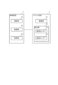
- FIG. 1 is a schematic diagram showing a schematic configuration of an operation system according to a first embodiment
- FIG. FIG. 2 is a block diagram showing configurations of a puppet body and a control device according to the first embodiment
- FIG. 2 is a block diagram showing configurations of a communication device and an operation device according to the first embodiment
- FIG. 3 is a schematic diagram showing the positional relationship between a user's hand, a position/orientation detection unit, and a vibration generation unit according to the first embodiment
- the perspective view which shows typically the operating device with which the operating system which concerns on 2nd Embodiment is provided.
- FIG. 1 is a schematic diagram showing a schematic configuration of an operation system 1 according to this embodiment.
- An operation system 1 according to this embodiment includes a puppet body 2, a control device 3, a communication device 4, a magnetic field generator 5, and an operation device 6, as shown in FIG.
- the operation device 6 remotely operates the puppet body 2 attached to the puppet PP via the control device 3 and the communication device 4, and the stimulation detected by the puppet body 2 is detected by the operation device 6. It is what the user perceives.
- the puppet PP is a hollow puppet having a body PP1, a head PP2, a right arm PP3 and a left arm PP4, and is made of cloth, for example.
- the magnetic field generator 5 also generates a magnetic field detected by a position/orientation detector 62 of the operation device 6, which will be described later.
- the puppet body 2 is an operation target operated by the operation device 6 .
- the puppet body 2 is inserted inside the puppet PP to operate the puppet PP.
- the puppet body 2 can also be said to be an operation device that is operated by a user other than the user who uses the operation device 6 and that gives external stimulation to the user through the operation device 6 .
- the puppet body 2 includes a driving section 21 as shown in FIG.
- the drive unit 21 operates according to control signals input from the control device 3 .
- the drive unit 21 operates the head PP2, the right arm PP3, and the left arm PP4.
- the drive section 21 has a support section 211 , a head drive section 212 , a right arm drive section 213 and a left arm drive section 214 .
- the support portion 211 is provided corresponding to the trunk portion PP1, and supports the head driving portion 212, the right arm driving portion 213, and the left arm driving portion 214.
- the head driving section 212 bends or extends the head PP2.
- the right arm drive section 213 bends or extends the right arm section PP3.
- the left arm drive section 214 bends or extends the left arm section PP4.
- the driving units 212 to 214 can be exemplified by a configuration having a plurality of links configured to be mutually bendable and a motor for operating the plurality of links.
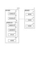
- FIG. 2 is a block diagram showing the configuration of the puppet body 2 and the control device 3.
- the puppet body 2 has a detection section 22 as shown in FIG.
- the detection unit 22 detects a stimulus acting on the puppet body 2 and outputs the detection result to the control device 3 .
- the detection unit 22 includes a tactile sensor 23 and a temperature sensor 24 .
- the tactile sensor 23 detects the approach of an object without contact. Also, the tactile sensor 23 detects the pressure applied to the contacting object. In other words, the tactile sensor 23 detects the pressure acting from the contacting object.
- the tactile sensors 23 are provided, for example, in the puppet body 2 at positions corresponding to the body PP1, the head PP2, the tip of the right arm PP3, and the tip of the left arm PP4.
- the tactile sensor 23 transmits the detection result to the control device 3 .
- the tactile sensor 23 has a function as a proximity sensor that detects the approach of an object and a function as a pressure sensor that detects pressure.
- the present invention is not limited to this, and the tactile sensor 23 may have one of a function as a proximity sensor and a function as a pressure sensor. At least one of a proximity sensor and a pressure sensor may be provided instead of the tactile sensor 23 .
- a temperature sensor 24 detects temperature.
- the temperature sensors 24 are provided, for example, at positions corresponding to the body PP1, head PP2, right arm PP3, and left arm PP4 in the puppet body 2, and transmit the detected temperatures to the control device 3.
- the control device 3 controls the operation of the puppet body 2 . Specifically, the control device 3 drives the drive unit 21 according to the operation information received from the communication device 4 to operate the puppet main body 2 and thus the puppet PP.
- the control device 3 includes a communication section 31, a storage section 32 and a control section 33, as shown in FIG.
- the communication unit 31 communicates with the puppet main body 2 and also communicates with the communication device 4 via the network NT. Under the control of the control unit 33 , the communication unit 31 outputs operation information received from the communication device 4 to the control unit 33 , and also outputs detection information indicating detection results by the detection unit 22 of the puppet body 2 to the communication device 4 .
- the communication unit 31 may be connected to the puppet main body 2 by wire, or may be connected by a communication method conforming to wireless communication standards such as Bluetooth (registered trademark) and IEEE 802.11.
- the storage unit 32 stores programs and data necessary for the operation of the control device 3.
- the storage unit 32 includes information on connection with the communication device 4, the type of the puppet body 2, and an operation program for operating the puppet body 2 based on the received operation information.
- the control unit 33 includes an arithmetic processing circuit such as a CPU (Central Processing Unit), and controls the operation of the puppet main body 2 according to a program stored in the storage unit 32. Specifically, the control unit 33 transmits a control signal for operating the drive unit 21 of the puppet body 2 based on the operation information received from the communication device 4 to the puppet body 2 via the communication unit 31 . Further, the control unit 33 transmits detection information indicating the detection result by the detection unit 22 of the puppet body 2 to the communication device 4 through the communication unit 31 .
- arithmetic processing circuit such as a CPU (Central Processing Unit)
- FIG. 3 is a block diagram showing the configuration of the communication device 4 and the operation device 6.
- the communication device 4 transmits to the control device 3 operation information corresponding to an operation signal input from the operation device 6 , and also based on detection information received from the control device 3 . to operate. That is, the communication device 4 is an operating device-side control device that controls part of the configuration of the operating device 6 .
- the communication device 4 has a communication section 41, a storage section 42, and a control section 43, as shown in FIG.
- the communication unit 41 not only communicates with the operation device 6, but also communicates with the control device 3 via the network NT. Under the control of the control unit 43, the communication unit 41 outputs detection information received from the control device 3 to the control unit 43, and also transmits operation information based on operation signals received from the operation device 6 to the control unit 3. .
- the communication unit 41 may be connected to the operation device 6 by wire, or may be connected by a communication method conforming to wireless communication standards such as Bluetooth (registered trademark) and IEEE 802.11.
- the storage unit 42 stores programs and data necessary for the operation of the communication device 4 .
- the storage unit 42 stores a conversion program for converting an operation signal received from the operation device 6 into operation information suitable for the control device 3 to operate the puppet body 2 .
- the storage unit 42 stores connection information for connecting with the control device 3 that controls the puppet body 2 that is the operation target of the operation device 6 . Therefore, when there are multiple sets of the control device 3 and the puppet main body 2 connected to the network NT, the storage unit 42 stores connection information for each control device 3 .
- the control unit 43 converts the operation signal received from the operation device 6 into the operation information based on the conversion program, and transmits the operation information to the control device 3 via the communication unit 41 . Further, the control unit 43 generates a control signal for operating the operation device 6 based on the detection information received from the control device 3 by the communication unit 41, transmits the generated control signal to the operation device 6, and controls the operation device. 6 controls part of the configuration.
- the operating device 6 remotely operates the puppet body 2 . Specifically, the operation device 6 detects the movement of the user, transmits an operation signal corresponding to the detected movement of the user to the communication device 4, and operates the puppet body 2 via the communication device 4 and the control device 3. Let In this embodiment, the operation device 6 detects the movement of the user's fingers (hand and fingers). In addition, the operation device 6 gives the user an external stimulus according to the control signal received from the communication device 4 based on the detection result of the detection unit 22 of the puppet body 2 .
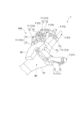
- FIG. 4 is a perspective view schematically showing the operating device 6.
- the operating device 6 includes a mounting portion 61 that is worn on one hand of the user.
- the wearing part 61 has a glove shape and is worn on one hand of the user. Therefore, the user can also wear a puppet similar to the puppet PP while wearing the operation device 6 on the hand so as to cover the outside of the operation device 6 .
- the mounting portion 61 be made of a stretchable material that can be brought into close contact with the user's hand.
- FIG. 5 is a schematic diagram showing the positional relationship between the user's hand, the position/orientation detection unit 62, and the vibration generation unit 65.
- the operating device 6 includes a position/orientation detection section 62, an approach detection section 63, a stimulus generation section 64, and a control section 68 as shown in FIG.
- the position/posture detection unit 62 is provided in the mounting unit 61 and detects the movement of the user's fingers. 4 and 5, the position/posture detection unit 62 includes a plurality of first position detection units 621 provided corresponding to each finger F, and a plurality of first position detection units 621 provided corresponding to positions other than the finger F on the user's hand. and a two-position detector 622 .
- the plurality of first position detectors 621 are provided on the mounting portion 61 at positions corresponding to the fingertips of each finger F and at positions on the nail side of each finger F. As shown in FIG. Specifically, as shown in FIG. 5, the first position detection unit 621 is provided for each finger F, and detects the position of the first position detection unit 621 as the position of the tip of the finger F to be detected. do.
- the plurality of first position detectors 621 includes first position detectors 6211-6215.
- the first position detection unit 6211 is provided for the first finger F1 (thumb)
- the first position detection unit 6212 is provided for the second finger F2 (index finger)
- the first position detection unit 6213 is provided for the third finger F3.
- the second position detection portion 622 is provided at a position corresponding to the back BH of the hand on the mounting portion 61, and detects the position of the second position detection portion 622 as the position of the back BH of the hand.
- each of the first position detection section 621 and the second position detection section 622 changes its resistance value depending on the strength and direction of the magnetic field generated outside the operation device 6 by the magnetic field generation device 5, which is a transmitter. It has a magnetic sensor. Then, each of the position detection units 621 and 622 calculates the position and orientation calculated based on the detection result of the magnetic sensor as the position and orientation of the corresponding finger and, by extension, the position and orientation of the finger.
- FIG. 6 is a schematic diagram showing the positional relationship between the user's hand and the proximity detector 63.
- the approach detection unit 63 is provided in the mounting unit 61 and detects the approach of an object to the user's fingers.
- the proximity detection unit 63 is configured by a proximity sensor provided on the outer surface of the mounting unit 61 at a position on the ventral side of the fingertip of each finger F, as shown in FIGS. 4 and 6 .
- the proximity detection unit 63 is provided in the mounting unit 61 at a position corresponding to the ventral portion of the fingertip of each finger F to be detected.
- the proximity detection unit 63 determines whether or not the object touches the finger when the user tries to grasp the object with the finger F of the hand wearing the operation device 6, that is, whether the hand wearing the operation device 6 has touched the object. Detect whether or not it is grabbed.
- the proximity sensors constituting the proximity detection unit 63 are provided for each of the fingers F1 to F5 of the user. It may also be provided on the palm PL and the back of the hand BH. Also, the above-described tactile sensor may be provided instead of the proximity sensor.
- the stimulus generating section 64 shown in FIG. 3 is provided in the mounting section 61 and operates based on a control signal received from the communication device 4 to apply an external stimulus to the user. That is, the stimulus generator 64 simulates the stimulus to the puppet PP based on the control signal based on the detection result of the detector 22 that detects the stimulus to the puppet body 2 .
- the stimulus generator 64 includes a vibration generator 65 , a temperature controller 66 and a presser 67 .
- the vibration generator 65 gives the user the illusion that an object is in contact with the user's fingers by applying vibration to the user.
- Each of the plurality of vibration generators 65 can employ a configuration including, for example, a voice coil motor.
- the vibration generating section 65 includes vibration generating sections 651 to 655 provided at positions corresponding to the respective fingers on the mounting section 61, as shown in FIGS.
- the vibration generating portion 651 is arranged at a position between the first joint of the first finger F1 and the joint at the base of the first finger F1 on the mounting portion 61 .
- the vibration generators 652 to 655 are provided at positions corresponding to the second finger F2, the third finger F3, the fourth finger F4 and the fifth finger F5 on the wearing part 61.
- FIG. More specifically, the vibration generators 652 to 655 are provided on the mounting portion 61 at corresponding positions between the first and second joints of the fingers F2 to F5.
- the user when vibration is applied directly to the fingertip, the user tends to have the illusion that an object touches the fingertip to which the vibration is applied.
- it is difficult to dispose the relatively large vibration generator 65 on the fingertip, and the operability of the operation device 6 deteriorates.
- the proximity detection section 63 and the temperature control section 66 are provided at the fingertip, it is difficult to secure a space for arranging the vibration generation section 65 at the fingertip.
- the vibration generator 651 is provided at a position between the first joint of the first finger F1 and the joint at the base of the first finger, and the vibration generators 652 to 655 are It is provided at a corresponding position between the first joint and the second joint of each of the second finger F2, the third finger F3, the fourth finger F4 and the fifth finger F5.
- the vibration generator 652 when vibration is generated by the vibration generator 652, the vibration is transmitted to the tip of the second finger F2, giving the user the illusion that vibration is directly applied to the tip of the second finger F2.
- the vibration generators 651 to 655 can be arranged at positions other than the fingertips, and the fingertips of the fingers F can be vibrated.
- the temperature control section 66 shown in FIG. 3 is provided at a position corresponding to the fingers of the wearing section 61, and gives the user a warm feeling and a cold feeling. Although detailed illustration is omitted, the temperature control units 66 are provided, for example, at the positions corresponding to the fingertips of the fingers F, the palm PL, and the back of the hand BH in the wearing unit 61, respectively. there is The temperature control section 66 is provided inside the mounting section 61 .
- the temperature control unit 66 can be composed of a thermoelectric conversion element such as a Peltier element, for example.
- the pressing portion 67 is provided at a position corresponding to the finger of the mounting portion 61 and presses the user's finger. Although illustration is omitted, the pressing portion 67 is provided at a position corresponding to each finger F, a position corresponding to the palm PL, and a position corresponding to the back of the hand BH on the mounting portion 61 . Specifically, among the plurality of pressing portions 67, five pressing portions 67 provided corresponding to each finger F are provided at positions corresponding to the tip of the finger F to be pressed, and press the tip of the finger F. . A plurality of pressing portions 67 may be provided at a position corresponding to the palm PL and a position corresponding to the back of the hand BH on the mounting portion 61 . As the pressing portion 67, a combination of an air pump and a silicon air chamber that expands or contracts by gas supplied from the air pump can be exemplified. Combinations can be exemplified.
- the control section 68 controls the operation of the operating device 6 .
- the control unit 68 is electrically connected to the position/orientation detection unit 62 , the proximity detection unit 63 and the stimulus generation unit 64 .
- the control unit 68 transmits to the communication device 4 an operation signal indicating the position and posture of the finger detected by the position/orientation detection unit 62 , and also transmits a detection signal indicating the result of detection by the proximity detection unit 63 to the communication device 4 .
- the control unit 68 operates the vibration generating unit 65 , the temperature adjusting unit 66 and the pressing unit 67 of the stimulation generating unit 64 based on the control signal received from the communication device 4 .
- the control section 68 is provided in the mounting section 61 at a position corresponding to the user's wrist.
- the operation system 1 includes an operation device 6 and a puppet body 2 that operates based on operation information based on the detection result of the first position detection section 621 of the operation device 6 .
- the puppet body 2 corresponds to an operation target.
- the operating device 6 includes a mounting section 61 , a first position detection section 621 and a stimulus generation section 64 .
- the wearing part 61 is worn on a user's finger.
- the first position detection section 621 is provided in the mounting section 61 and detects the position of the corresponding finger F.
- the stimulus generating section 64 is provided at a position corresponding to the user's finger F on the mounting section 61, and applies an external stimulus to the user.
- the position of the finger F of the user wearing the operating device 6 and the posture of the finger F can be detected by the first position detection section 621 .
- the stimulus generator 64 can apply an external stimulus to the finger F of the user. Therefore, according to the position and posture of the finger F detected by the first position detection unit 621, the finger F to be detected by the first position detection unit 621 or another finger F can be given an external stimulus. Therefore, the versatility of the operating device 6 can be enhanced.
- the operation system 1 that can operate an operation target (for example, the puppet main body 2) using the operation device 6 and provide feedback to the user of stimuli given to the operation target from the outside.
- the first position detection section 621 is provided on the user's fingernail side of the mounting section 61 . According to such a configuration, it is not necessary to provide the first position detection section 621 at the tip of the finger F, which is the detection target of the first position detection section 621 . Therefore, compared to the case where the first position detection unit 621 is provided according to the fingertip of the finger F that is the target of position detection, the degree of freedom of the fingertip that is the target of position detection can be increased.
- the stimulus generator 64 includes a vibration generator 65 .
- Vibration generators 652 to 655 of the vibration generators 65 are provided between the first and second joints of the corresponding fingers on the mounting part 61 and generate vibrations. According to such a configuration, when vibration is generated by the vibration generating units 652 to 655 arranged at the above positions, the vibration can be transmitted to the fingertip of the corresponding finger F, and when the fingertip is directly vibrated, It can give users the same illusion as Accordingly, since it is not necessary to provide the vibration generating section 65 on the fingertip, the degree of freedom of the fingertip can be increased compared to the case where the vibration generating section 65 is provided on the fingertip.
- the operating device 6 includes an approach detection section 63 that is provided on the pad side of the user's fingertip in the mounting section 61 and detects the approach of an object.
- the approach detection unit 63 can accurately detect the approach of an object to the user's fingertip.
- the stimulus generator 64 includes a temperature controller 66 capable of adjusting temperature. According to such a configuration, it is possible to give the user a cool feeling and a warm feeling. Therefore, the versatility of the operation device 6 can be enhanced, and the contact of another user or an object with respect to the operation target can be perceived by the user operating the operation device 6 by the temperature.
- the stimulation generating section 64 includes a pressing section 67 that presses fingers.
- the pressing portion 67 can give a reaction force when the user grips an object, or a tactile sensation as if another person touched the user's hand. Therefore, the versatility of the operating device 6 can be enhanced.
- the operating device 6 includes a second position detection section 622 provided at a position corresponding to the back BH of the user's hand in the mounting section 61 and detecting the position of the back BH of the hand. According to such a configuration, the motion of turning the user's wrist can be detected by the second position detection section 622 . Therefore, the movement of the user's hand can be detected in detail.
- the mounting portion 61 is shaped like a glove that covers the fingers of the user. According to such a configuration, it is possible to make it easier for the user to wear the operating device 6 on the hand.
- the first position detection section 621 has a magnetic sensor that detects an externally generated magnetic field.
- the second position detector 622 is also the same. According to such a configuration, for example, compared to a configuration in which the first position detection unit 621 includes an exoskeleton attached to the finger F and a movement amount detection device that detects the movement amount of the exoskeleton, The position of the finger F can be detected without disturbing the movement of the finger F.
- the operation device 6 is provided at a position corresponding to the user's wrist on the mounting section 61 and includes a control section 68 that controls the stimulus generation section 64 .
- the control section 68 can be arranged at a position where the movement of the hand is less likely to be hindered. Therefore, it is possible to suppress a decrease in the degree of freedom of the user's fingers.
- the operating system according to this embodiment has the same configuration as the operating system 1 according to the first embodiment, but differs in the configuration of the operating device.
- parts that are the same as or substantially the same as those already described are denoted by the same reference numerals, and descriptions thereof are omitted.
- FIG. 7 is a schematic diagram showing the operating device 7 included in the operating system according to this embodiment.
- the operation system according to the present embodiment has the same configuration and functions as the operation system 1 according to the first embodiment, except that it includes an operation device 7 shown in FIG. 7 instead of the operation device 6 according to the first embodiment.
- the operation system according to the present embodiment includes a puppet body 2 arranged inside the puppet PP, a control device 3, a communication device 4, and an operation device 7.
- the operating device 7 communicates with the communication device 4 to remotely operate the puppet main body 2 shown in the first embodiment.
- the operation device 7 detects the movement of the user's fingers, transmits an operation signal corresponding to the detected movement of the fingers to the communication device 4, and also provides an external stimulus to the user according to the control signal received from the communication device 4.
- the operation device 7 has the same configuration and functions as the operation device 6 except that a stimulus generator 64A is provided instead of the stimulus generator 64 . That is, the operating device 7 includes a mounting section 61 , a position/orientation detection section 62 , an approach detection section 63 , a stimulus generation section 64A, and a control section 68 .
- a stimulus generator 64A is provided instead of the stimulus generator 64 .
- control unit 68 is provided at a position corresponding to the back of the hand BH on the mounting unit 61 .
- the control section 68 may be provided at a position corresponding to the user's wrist, like the control section 68 in the operating device 6 according to the first embodiment.
- the stimulus generator 64A includes a vibration generator 65, a temperature controller 66, and a presser 67, as well as a reaction force generator 71, like the stimulus generator 64 according to the first embodiment.
- the reaction force generator 71 generates a reaction force against the movement of the user's fingers, and gives the user the feeling that the fingers are touching an object.
- the reaction force generation unit 71 generates a reaction force that restricts the movement of the user's finger F, and gives the user the feeling that the finger F is touching an object.
- the reaction force generator 71 includes a reaction force generator 711 that applies a reaction force to the first finger F1, a reaction force generator 712 that applies a reaction force to the second finger F2, and a reaction force generator that applies a reaction force to the third finger F3. It includes a force generator 713, a reaction force generator 714 that applies a reaction force to the fourth finger F4, and a reaction force generator 715 that applies a reaction force to the fifth finger F5.
- Each of the reaction force generators 711 to 715 has a link mechanism 72 and a resistance section 73 .
- the link mechanism 72 connects the finger F to which the reaction force is applied and the resistance portion 73 .
- the link mechanism 72 is configured with a plurality of links that are bendably connected to each other, and is displaced according to the movement of the connected finger F. As shown in FIG. One end of the link mechanism 72 is connected to the tip of the finger F on which the reaction force is applied, and the other end of the link mechanism 72 is connected to the resistance section 73 .
- the operating device 7 is a so-called exoskeleton controller.
- the resistance unit 73 changes the resistance against the displacement of the link mechanism 72, which is displaced according to the movement of the finger F to which the reaction force is applied, so that the reaction force against the movement of the finger F is applied to the finger F.
- the resistance portion 73 of the reaction force generating portion 712 increases resistance to displacement of the link mechanism 72 that is displaced according to the bending motion of the second finger F2 when the second finger F2 bends. It is made difficult to bend the finger F2. As a result, since a reaction force to the bending motion of the second finger F2 acts on the second finger F2, the user can perceive the illusion that an object is in contact with the second finger F2.
- a displacement detector such as a potentiometer for detecting the displacement of the link mechanism 72 is provided. It may be configured as a first position detection section that detects the position of F.
- the present invention is not limited to the above-described embodiments, and includes modifications, improvements, and the like within the scope of achieving the object of the present invention.
- the position/orientation detection section 62 including the first position detection section 621 and the second position detection section 622 has a magnetic sensor that detects magnetism.
- the detection method for detecting the position and orientation of the finger by the position/orientation detection unit is not limited to this, and may be another method.
- the position/orientation detection section 62 includes the first position detection section 621 (6211 to 6215) provided in the mounting section 61 at a position corresponding to the fingertip of the finger F to be detected, and the position detection section 621 corresponding to the back of the hand BH. and a second position detector 622 provided at a position.
- the present invention is not limited to this, and the position/orientation detection section 62 may include at least one first position detection section among the first position detection sections 6211 to 6215.
- the second position detection section 622 may It can be omitted.
- the first position detection unit 621 is provided in the mounting unit 61 so as to correspond to the position on the nail side of the fingertip of the finger F that is the object of detection.
- the first position detection section may be provided anywhere.
- the vibration generators 652 to 655 provided for the second finger F2, the third finger F3, the fourth finger F4, and the fifth finger F5 correspond to the first joint of each finger F in the mounting portion 61. It is assumed that it is provided between the second joint.
- the present invention is not limited to this, and the positions where the vibration generators 652 to 655 are provided may be other positions, and the vibration generator 65 may be omitted.
- the operating devices 6 and 7 are provided with the proximity detection section 63 provided in the mounting section 61 on the abdomen side of the user's fingertip.
- the present invention is not limited to this, and the approach detection unit 63 may be omitted.
- the position of the proximity detection part 63 does not have to be the position on the pad side of the fingertip in the mounting part 61, and can be changed as appropriate.
- the stimulus generator 64 includes the temperature controller 66 . That is, the operating devices 6 and 7 are provided with a temperature control section 66 capable of controlling the temperature.
- the present invention is not limited to this, and the temperature control section 66 may be omitted.
- the position of the temperature control unit 66 is not limited to the above, and may be other positions.
- the stimulus generating section 64 includes the pressing section 67 .
- the operating devices 6 and 7 are provided with a pressing portion 67 for pressing the fingers of the user.
- the present invention is not limited to this, and the pressing portion 67 may be omitted.
- the position of the pressing portion 67 is not limited to the above, and may be another position.
- the operating devices 6 and 7 are provided in the mounting section 61 at a position corresponding to the back BH of the user's hand, and include the second position detection section 622 that detects the position of the back BH of the hand.
- the present invention is not limited to this, and the second position detection section 622 may be omitted.
- the wearing part 61 is shaped like a glove that covers the user's fingers.
- the shape of the mounting portion 61 is not limited to this, and can be changed as appropriate as long as each component of the operating devices 6 and 7 can be arranged.
- the mounting portion 61 may be band-shaped, or may have the same shape as the puppet PP.
- the operating device 6 is provided at a position corresponding to the user's wrist on the wearing section 61 and includes the control section 68 that controls the stimulus generating section 64 .
- the control unit 68 may be omitted if, for example, the configuration of the operation devices 6 and 7 such as the position/orientation detection unit 62 and the stimulus generation unit 64 are directly connected to the communication device 4 .
- the control unit 68 may be provided at a position corresponding to the back of the hand on the mounting part 61, or may be provided at another position. good too. That is, the position of the control unit 68 can be changed as appropriate, and may be a position other than the finger of the user.
- the operation devices 6 and 7 configure an operation system together with an operation target (for example, the puppet main body 2) that operates based on operation information based on the detection result of the position/orientation detection unit 62.
- the operation target of the operation devices 6 and 7 may not be the puppet main body 2, and may be another configuration.
- Such manipulation targets may be, for example, robot hands and manipulators.
- the operation devices 6 and 7 operate the puppet main body 2 via the control device 3 and the communication device 4 communicating via the network NT.
- the operation devices 6 and 7 are not limited to this, and may directly operate the puppet body 2 that is the operation target.
- the operation device includes a mounting section that is mounted on a user's finger, a first position detection section that is provided in the mounting section and detects the position of the finger, and a a stimulus generator provided at a location for applying an external stimulus to the user.
- the position of the finger of the user wearing the operating device and the posture of the finger can be detected by the first position detection section.
- the stimulus generator can apply an external stimulus to the user's finger. Therefore, an external stimulus can be applied to the finger whose position is to be detected by the first position detection unit or to another finger according to the position and orientation of the finger detected by the first position detection unit. Therefore, the versatility of the operating device can be enhanced.
- the first position detection section may be provided on the user's fingernail side of the mounting section. According to such a configuration, it is not necessary to provide the first position detection section at the fingertip of the finger whose position is to be detected by the first position detection section. Therefore, compared with the case where the first position detection unit is provided according to the fingertip of the finger that is the target of position detection, the degree of freedom of the fingertip that is the target of position detection can be increased.
- the stimulus generator is provided between the user's first and second finger joints in the attachment section, and generates vibration.
- a vibration generator may be included. According to such a configuration, when vibration is generated by the vibration generating section arranged at the above position, the vibration can be transmitted to the fingertip, giving the user the same illusion as when the fingertip is directly vibrated. can. Accordingly, since it is not necessary to provide the vibration generating section at the fingertip, the degree of freedom of the fingertip can be increased compared to the case where the vibration generating section is provided at the fingertip.
- the operating device according to any one of [1] to [3], further comprising an approach detection section provided on the pad side of the fingertip of the user in the attachment section and detecting approach of an object. good too.
- the proximity detection section since the proximity detection section that detects the proximity of an object is provided on the ventral side of the fingertip, the proximity detection section can accurately detect the proximity of the object to the user's fingertip.
- the stimulation generating section may include a temperature control section capable of controlling temperature. According to such a configuration, it is possible to give the user a cool feeling and a warm feeling. Therefore, the versatility of the operating device can be enhanced, and the contact of another user or an object to the operation target operated by the operating device can be perceived by the user operating the operating device by the temperature.
- the stimulus generating section may include a pressing section that presses the fingers.
- the pressing portion can impart a reaction force when the user grips an object, or a tactile sensation as if another person touched the user's hand. Therefore, the versatility of the operating device can be enhanced.
- a second position detection section provided at a position corresponding to the back of the hand of the user in the mounting section and detecting the position of the back of the hand.
- the motion of turning the user's wrist can be detected by the second position detection section. Therefore, the movement of the user's hand can be detected in detail.
- the attachment section may be shaped like a glove that covers the fingers of the user. According to such a configuration, it is possible to make it easier for the user to wear the operating device on the hand.
- the first position detection section may have a magnetic sensor that detects an externally generated magnetic field.
- the first position detection unit includes an exoskeleton attached to the finger and a movement amount detection device that detects the movement amount of the exoskeleton, the position of the finger is reduced. Finger position can be detected without hindering movement.
- the operation device according to any one of [1] to [9], further comprising a control unit provided at a position corresponding to the wrist of the user in the wearing unit and controlling the stimulus generation unit.
- the control section can be arranged at a position where the movement of the hand is less likely to be hindered. Therefore, it is possible to suppress a decrease in the degree of freedom of the user's fingers.
- An operation system includes the operation device according to any one of [1] to [10], and an operation target that operates based on operation information based on the detection result of the first position detection unit. . According to such a configuration, it is possible to obtain the same effects as those of the operating device described above. Accordingly, it is possible to configure an operation system capable of performing the operation of the operation target by the operation device and the feedback to the user of the stimulus given to the operation target from the outside.
Landscapes
- Engineering & Computer Science (AREA)
- General Engineering & Computer Science (AREA)
- Theoretical Computer Science (AREA)
- Human Computer Interaction (AREA)
- Physics & Mathematics (AREA)
- General Physics & Mathematics (AREA)
- Position Input By Displaying (AREA)
- Mechanical Control Devices (AREA)
Abstract
操作装置(6,7)は、ユーザーの手指に装着される装着部(61)と、前記装着部に設けられ、前記指の位置を検出する第1位置検出部(621)と、前記装着部において前記ユーザーの指に応じた位置に設けられ、前記ユーザーに外的刺激を付与する刺激発生部(64,64A)と、を備える。
Description
本発明は、操作装置及び操作システムに関する。
従来、ハンドパペットの中に装着されて、ハンドパペットを動作させるパペット操作装置と、パペット操作装置を遠隔操作する制御モジュールと、を備えるハンドパペットマニピュレーションシステムが知られている(例えば特許文献1参照)。
特許文献1に記載のハンドパペットマニピュレーションシステムでは、制御モジュールは、ユーザーの手に嵌められて利用され、ユーザーの手の動きを検出するデータグローブを備える。データグローブは、ユーザーの手の動きにより変化する物理量を測定する複数種類のセンサーを備える。データグローブによって測定された物理量のデータは、変換モジュールに送信され、変換モジュールによって様々な制御信号に変換される。変換された制御信号は、パペット操作装置に送信され、パペット操作装置は、制御信号に基づいて、ハンドパペットを動作させる。
特許文献1に記載のハンドパペットマニピュレーションシステムでは、制御モジュールは、ユーザーの手に嵌められて利用され、ユーザーの手の動きを検出するデータグローブを備える。データグローブは、ユーザーの手の動きにより変化する物理量を測定する複数種類のセンサーを備える。データグローブによって測定された物理量のデータは、変換モジュールに送信され、変換モジュールによって様々な制御信号に変換される。変換された制御信号は、パペット操作装置に送信され、パペット操作装置は、制御信号に基づいて、ハンドパペットを動作させる。
近年、よりリアルな操作感が要望されている。
しかしながら、特許文献1に記載のハンドパペットマニピュレーションシステムでは、パペット操作装置に加わった刺激を、制御モジュールを操作するユーザーが感知できないという問題がある。
しかしながら、特許文献1に記載のハンドパペットマニピュレーションシステムでは、パペット操作装置に加わった刺激を、制御モジュールを操作するユーザーが感知できないという問題がある。
本発明の第1態様に係る操作装置は、ユーザーの手指に装着される装着部と、前記装着部に設けられ、前記指の位置を検出する第1位置検出部と、前記装着部において前記ユーザーの指に応じた位置に設けられ、前記ユーザーに外的刺激を付与する刺激発生部と、を備える。
本発明の第2態様に係る操作システムは、上記第1態様に係る操作装置と、前記第1位置検出部による検出結果に基づく操作情報に基づいて動作する操作対象と、を備える。
[第1実施形態]
以下、本発明の第1実施形態について、図面に基づいて説明する。
[操作システムの概略構成]
図1は、本実施形態に係る操作システム1の概略構成を示す模式図である。
本実施形態に係る操作システム1は、図1に示すように、パペット本体2、制御装置3、通信装置4、磁場発生装置5及び操作装置6を備える。操作システム1では、操作装置6が、制御装置3及び通信装置4を介して、パペットPPに装着されるパペット本体2を遠隔操作するとともに、パペット本体2にて検出された刺激を操作装置6がユーザーに知覚させるものである。
なお、パペットPPは、胴部PP1、頭部PP2、右腕部PP3及び左腕部PP4を有する中空の人形であり、例えば布によって形成されている。
また、磁場発生装置5は、操作装置6の後述する位置姿勢検出部62によって検出される磁場を発生させる。
[パペット本体の構成]
パペット本体2は、操作装置6によって操作される操作対象である。パペット本体2は、パペットPPの内部に挿入されて、パペットPPを動作させる。また、パペット本体2は、操作装置6を利用するユーザーとは異なる他のユーザーによって操作され、操作装置6によってユーザーに外的刺激を付与する操作装置とも言える。
パペット本体2は、操作装置6によって操作される操作対象である。パペット本体2は、パペットPPの内部に挿入されて、パペットPPを動作させる。また、パペット本体2は、操作装置6を利用するユーザーとは異なる他のユーザーによって操作され、操作装置6によってユーザーに外的刺激を付与する操作装置とも言える。
パペット本体2は、図1に示すように、駆動部21を備える。
駆動部21は、制御装置3から入力する制御信号に応じて動作する。駆動部21は、頭部PP2、右腕部PP3及び左腕部PP4を動作させる。駆動部21は、支持部211、頭部駆動部212、右腕駆動部213及び左腕駆動部214を有する。
支持部211は、胴部PP1に対応して設けられ、頭部駆動部212、右腕駆動部213及び左腕駆動部214を支持する。
頭部駆動部212は、頭部PP2を屈曲又は伸長させる。右腕駆動部213は、右腕部PP3を屈曲又は伸長させる。左腕駆動部214は、左腕部PP4を屈曲又は伸長させる。駆動部212~214は、互いに屈曲可能に構成された複数のリンクと、複数のリンクを動作させるモーターとを有する構成を例示できる。
図2は、パペット本体2及び制御装置3の構成を示すブロック図である。
パペット本体2は、図2に示すように、検出部22を有する。
検出部22は、パペット本体2に作用する刺激を検出し、検出結果を制御装置3に出力する。検出部22は、触覚センサー23及び温度センサー24を備える。
触覚センサー23は、非接触にて物体の接近を検出する。また、触覚センサー23は、接触した物体に加えている圧力を検出する。換言すると、触覚センサー23は、接触した物体から作用する圧力を検出する。触覚センサー23は、例えばパペット本体2において胴部PP1と、頭部PP2と、右腕部PP3の先端部と、左腕部PP4の先端部とのそれぞれに対応する位置に設けられる。触覚センサー23は、検出結果を制御装置3に送信する。なお、触覚センサー23は、物体の接近を検出する近接センサーとしての機能と、圧力を検出する圧力センサーとしての機能と、を有する。しかしながら、これに限らず、触覚センサー23は、近接センサーとしての機能と、圧力センサーとしての機能とのうち、一方の機能を有するものでもよい。また、触覚センサー23に代えて、近接センサー及び圧力センサーのうち少なくとも一方のセンサーを設けてもよい。
温度センサー24は、温度を検出する。温度センサー24は、例えばパペット本体2において胴部PP1、頭部PP2、右腕部PP3及び左腕部PP4のそれぞれに対応する位置に設けられ、検出した温度を制御装置3に送信する。
[制御装置の構成]
制御装置3は、パペット本体2の動作を制御する。具体的に、制御装置3は、通信装置4から受信される操作情報に応じて駆動部21を駆動させて、パペット本体2ひいてはパペットPPを動作させる。制御装置3は、図2に示すように、通信部31、記憶部32及び制御部33を備える。
通信部31は、パペット本体2と通信する他、ネットワークNTを介して通信装置4と通信する。通信部31は、制御部33による制御の下、通信装置4から受信される操作情報を制御部33に出力する他、パペット本体2の検出部22による検出結果を示す検出情報を通信装置4に送信する。なお、通信部31は、パペット本体2と有線にて接続されてもよく、Bluetooth(登録商標)及びIEEE 802.11等の無線通信規格に準拠した通信方式にて接続されてもよい。
記憶部32は、制御装置3の動作に必要なプログラム及びデータを記憶している。例えば記憶部32は、通信装置4との接続情報、パペット本体2の種別、及び、受信された操作情報に基づいてパペット本体2を動作させる動作プログラム等が挙げられる。
制御部33は、CPU(Central Processing Unit)等の演算処理回路を備え、記憶部32に記憶されたプログラムに則って、パペット本体2の動作を制御する。具体的に、制御部33は、通信装置4から受信した操作情報に基づいてパペット本体2の駆動部21を動作させる制御信号を、通信部31を介してパペット本体2に送信する。また、制御部33は、パペット本体2の検出部22による検出結果を示す検出情報を通信部31によって通信装置4に送信する。
[通信装置の構成]
図3は、通信装置4及び操作装置6の構成を示すブロック図である。
通信装置4は、図1に示すように、操作装置6から入力する操作信号に応じた操作情報を制御装置3に送信する他、制御装置3から受信された検出情報に基づいて、操作装置6を動作させる。すなわち、通信装置4は、操作装置6が有する構成の一部を制御する操作装置側制御装置である。通信装置4は、図3に示すように、通信部41、記憶部42及び制御部43を有する。
図3は、通信装置4及び操作装置6の構成を示すブロック図である。
通信装置4は、図1に示すように、操作装置6から入力する操作信号に応じた操作情報を制御装置3に送信する他、制御装置3から受信された検出情報に基づいて、操作装置6を動作させる。すなわち、通信装置4は、操作装置6が有する構成の一部を制御する操作装置側制御装置である。通信装置4は、図3に示すように、通信部41、記憶部42及び制御部43を有する。
通信部41は、操作装置6と通信する他、ネットワークNTを介して制御装置3と通信する。通信部41は、制御部43による制御の下、制御装置3から受信された検出情報を制御部43に出力する他、操作装置6から受信する操作信号に基づく操作情報を制御装置3に送信する。なお、通信部41は、操作装置6と有線にて接続されてもよく、Bluetooth(登録商標)及びIEEE 802.11等の無線通信規格に準拠した通信方式にて接続されてもよい。
記憶部42は、通信装置4の動作に必要なプログラム及びデータを記憶している。例えば、記憶部42は、操作装置6から受信された操作信号を、制御装置3がパペット本体2を動作させるのに適した操作情報に変換する変換プログラムを記憶している。また例えば、記憶部42は、操作装置6の操作対象であるパペット本体2を制御する制御装置3と接続するための接続情報を記憶している。このため、ネットワークNTに接続された制御装置3及びパペット本体2の組が複数存在する場合には、記憶部42は、制御装置3毎に接続情報を記憶している。
制御部43は、変換プログラムに基づいて、操作装置6から受信された操作信号を上記操作情報に変換し、操作情報を通信部41によって制御装置3に送信する。また、制御部43は、通信部41によって制御装置3から受信された検出情報に基づいて操作装置6を動作させる制御信号を生成し、生成した制御信号を操作装置6に送信して、操作装置6が有する構成の一部を制御する。
[操作装置の構成]
操作装置6は、パペット本体2を遠隔操作する。具体的に、操作装置6は、ユーザーの動きを検出し、検出したユーザーの動きに応じた操作信号を通信装置4に送信して、通信装置4及び制御装置3を介してパペット本体2を動作させる。本実施形態では、操作装置6は、ユーザーの手指(手及び指)の動きを検出する。この他、操作装置6は、パペット本体2の検出部22による検出結果に基づいて通信装置4から受信する制御信号に応じてユーザーに外的刺激を付与する。
操作装置6は、パペット本体2を遠隔操作する。具体的に、操作装置6は、ユーザーの動きを検出し、検出したユーザーの動きに応じた操作信号を通信装置4に送信して、通信装置4及び制御装置3を介してパペット本体2を動作させる。本実施形態では、操作装置6は、ユーザーの手指(手及び指)の動きを検出する。この他、操作装置6は、パペット本体2の検出部22による検出結果に基づいて通信装置4から受信する制御信号に応じてユーザーに外的刺激を付与する。
図4は、操作装置6を模式的に示す斜視図である。
操作装置6は、図4に示すように、ユーザーの片手に装着される装着部61を備える。
装着部61は、グローブ状をなし、ユーザーの片手の手指に装着される。このため、ユーザーは、操作装置6を手に装着しながらパペットPPと同様のパペットを、操作装置6の外側に被せるように手に装着することも可能である。装着部61は、ユーザーの手に密着可能で、かつ、伸縮可能な材料によって形成されていることが好ましい。
操作装置6は、図4に示すように、ユーザーの片手に装着される装着部61を備える。
装着部61は、グローブ状をなし、ユーザーの片手の手指に装着される。このため、ユーザーは、操作装置6を手に装着しながらパペットPPと同様のパペットを、操作装置6の外側に被せるように手に装着することも可能である。装着部61は、ユーザーの手に密着可能で、かつ、伸縮可能な材料によって形成されていることが好ましい。
図5は、ユーザーの手と位置姿勢検出部62及び振動発生部65との位置関係を示す模式図である。
操作装置6は、装着部61の他、図3に示すように、位置姿勢検出部62、接近検出部63、刺激発生部64及び制御部68を備える。
位置姿勢検出部62は、装着部61に設けられてユーザーの手指の動きを検出する。位置姿勢検出部62は、図4及び図5に示すように、各指Fに応じて設けられる複数の第1位置検出部621と、ユーザーの手において指F以外の位置に応じて設けられる第2位置検出部622と、を含む。
操作装置6は、装着部61の他、図3に示すように、位置姿勢検出部62、接近検出部63、刺激発生部64及び制御部68を備える。
位置姿勢検出部62は、装着部61に設けられてユーザーの手指の動きを検出する。位置姿勢検出部62は、図4及び図5に示すように、各指Fに応じて設けられる複数の第1位置検出部621と、ユーザーの手において指F以外の位置に応じて設けられる第2位置検出部622と、を含む。
複数の第1位置検出部621は、装着部61において各指Fの指先に応じた位置で、かつ、各指Fの爪側の位置に設けられる。詳述すると、第1位置検出部621は、図5に示すように、各指Fに応じて設けられ、第1位置検出部621の位置を、検出対象である指Fの指先の位置として検出する。複数の第1位置検出部621は、第1位置検出部6211~6215を含む。
第1位置検出部6211は、第1指F1(親指)に設けられ、第1位置検出部6212は、第2指F2(人差し指)に設けられ、第1位置検出部6213は、第3指F3(中指)に設けられ、第1位置検出部6214は、第4指F4(薬指)に設けられ、第1位置検出部6215は、第5指F5(小指)に設けられる。
第2位置検出部622は、装着部61において手の甲BHに応じた位置に設けられ、第2位置検出部622の位置を手の甲BHの位置として検出する。
本実施形態では、第1位置検出部621及び第2位置検出部622のそれぞれは、トランスミッターである磁場発生装置5によって操作装置6の外部に発生した磁界の強さ及び向きによって抵抗値が変化する磁気センサーを有する。そして、各位置検出部621,622は、磁気センサーの検出結果に基づいて算出される位置及び姿勢を、対応する指の位置及び姿勢、ひいては、手指の位置及び姿勢として算出する。
図6は、ユーザーの手と接近検出部63との位置関係を示す模式図である。
接近検出部63は、装着部61に設けられ、ユーザーの手指に対する物体の接近を検出する。具体的に、接近検出部63は、図4及び図6に示すように、装着部61の外面において各指Fの指先の腹側の位置に設けられた近接センサーによって構成されている。すなわち、接近検出部63は、装着部61において、検出対象である各指Fの指先の腹側の部分に応じた位置に設けられている。接近検出部63は、ユーザーが操作装置6を装着した手の指Fによって物体を掴もうとした場合に、物体が指に接触したか否か、すなわち、操作装置6を装着した手が物体を掴んだか否かを検出する。
本実施形態では、接近検出部63を構成する近接センサーは、ユーザーの各指F1~F5に応じて設けられているが、例えば指F1~F5に代えて、或いは、各指F1~F5に加えて手のひらPL及び手の甲BHにも設けられていてもよい。また、近接センサーに代えて、上記した触覚センサーを設けてもよい。
図3に示す刺激発生部64は、装着部61に設けられ、通信装置4から受信する制御信号に基づいて動作して、ユーザーに外的刺激を作用させるものである。すなわち、刺激発生部64は、パペット本体2に対する刺激を検出する検出部22の検出結果に基づく制御信号に基づいて、パペットPPに対する刺激を疑似的に再現する。
刺激発生部64は、振動発生部65、温度調節部66及び押圧部67を含む。
刺激発生部64は、振動発生部65、温度調節部66及び押圧部67を含む。
振動発生部65は、ユーザーに振動を付与することによって、ユーザーの手指に物体が接触したような錯覚を生じさせる。複数の振動発生部65のそれぞれは、例えばボイスコイルモーターを有する構成を採用できる。
本実施形態では、振動発生部65は、図4及び図5に示すように、装着部61において各指に応じた位置に設けられる振動発生部651~655を含む。
本実施形態では、振動発生部65は、図4及び図5に示すように、装着部61において各指に応じた位置に設けられる振動発生部651~655を含む。
振動発生部651は、装着部61において第1指F1の第1関節と第1指の付け根の関節との間に応じた位置に配置されている。
振動発生部652~655は、装着部61において第2指F2、第3指F3、第4指F4及び第5指F5に応じた位置に設けられる。詳述すると、振動発生部652~655は、装着部61において各指F2~F5の第1関節と第2関節との間に応じた位置に設けられている。
振動発生部652~655は、装着部61において第2指F2、第3指F3、第4指F4及び第5指F5に応じた位置に設けられる。詳述すると、振動発生部652~655は、装着部61において各指F2~F5の第1関節と第2関節との間に応じた位置に設けられている。
ここで、指先に振動が直接付与されると、ユーザーは、振動が付与された指先に物が接触したと錯覚しやすい。しかしながら、サイズが比較的大きい振動発生部65を指先に配置することは難しい他、操作装置6の操作性が低下する。本実施形態に係る操作装置6では、接近検出部63及び温度調節部66が指先に設けられることから、振動発生部65を配置するスペースを指先に確保することは難しい。
これに対し、本実施形態では、振動発生部651は、第1指F1の第1関節と第1指の付け根の関節との間に応じた位置に設けられ、振動発生部652~655は、第2指F2、第3指F3、第4指F4及び第5指F5のそれぞれの第1関節と第2関節との間に応じた位置に設けられている。
これにより、例えば振動発生部652にて振動を発生させると、第2指F2の指先に振動が伝わり、第2指F2の指先に振動が直接付与されているような錯覚をユーザーに付与できる。このように、振動発生部651~655を指先以外の位置に配置でき、各指Fの指先に振動を付与できる。
これにより、例えば振動発生部652にて振動を発生させると、第2指F2の指先に振動が伝わり、第2指F2の指先に振動が直接付与されているような錯覚をユーザーに付与できる。このように、振動発生部651~655を指先以外の位置に配置でき、各指Fの指先に振動を付与できる。
図3に示す温度調節部66は、装着部61の手指に応じた位置に設けられ、ユーザーに温感及び冷感を付与する。温度調節部66は、詳しい図示を省略するが、例えば装着部61において各指Fの指先に対応する位置と、手のひらPLに対応する位置と、手の甲BHに対応する位置とのそれぞれに設けられている。温度調節部66は、装着部61の内側に設けられている。温度調節部66は、例えばペルチェ素子等の熱電変換素子によって構成できる。
押圧部67は、装着部61の手指に応じた位置に設けられ、ユーザーの手指を押圧する。図示を省略するが、押圧部67は、装着部61において各指Fに応じた位置と、手のひらPLに応じた位置と、手の甲BHに応じた位置とに設けられている。詳述すると、複数の押圧部67のうち、各指Fに応じて設けられる5つの押圧部67は、押圧対象である指Fの指先に応じた位置に設けられ、指Fの指先を押圧する。なお、装着部61において手のひらPLに応じた位置、及び、手の甲BHに応じた位置には、押圧部67は、複数設けられていてもよい。押圧部67としては、エアポンプと、エアポンプから供給される気体によって拡大又は縮小するシリコン製気室との組合せを例示できる他、圧電素子と、圧電素子によって移動して手指を押圧する押圧片との組合せを例示できる。
制御部68は、操作装置6の動作を制御する。制御部68は、位置姿勢検出部62、接近検出部63及び刺激発生部64と電気的に接続されている。制御部68は、位置姿勢検出部62によって検出された手指の位置及び姿勢を示す操作信号を通信装置4に送信する他、接近検出部63による検出結果を示す検出信号を通信装置4に送信する。また、制御部68は、通信装置4から受信した制御信号に基づいて、刺激発生部64の振動発生部65、温度調節部66及び押圧部67を動作させる。
本実施形態では、制御部68は、図5に示すように、装着部61においてユーザーの手首に応じた位置に設けられている。
本実施形態では、制御部68は、図5に示すように、装着部61においてユーザーの手首に応じた位置に設けられている。
[第1実施形態の効果]
以上説明した本実施形態に係る操作システム1は、以下の効果を奏する。
操作システム1は、操作装置6と、操作装置6の第1位置検出部621による検出結果に基づく操作情報に基づいて動作するパペット本体2と、を備える。パペット本体2は、操作対象に相当する。
操作装置6は、装着部61と、第1位置検出部621と、刺激発生部64と、を備える。装着部61は、ユーザーの手指に装着される。第1位置検出部621は、装着部61に設けられ、対応する指Fの位置を検出する。刺激発生部64は、装着部61においてユーザーの指Fに応じた位置に設けられ、ユーザーに外的刺激を付与する。
以上説明した本実施形態に係る操作システム1は、以下の効果を奏する。
操作システム1は、操作装置6と、操作装置6の第1位置検出部621による検出結果に基づく操作情報に基づいて動作するパペット本体2と、を備える。パペット本体2は、操作対象に相当する。
操作装置6は、装着部61と、第1位置検出部621と、刺激発生部64と、を備える。装着部61は、ユーザーの手指に装着される。第1位置検出部621は、装着部61に設けられ、対応する指Fの位置を検出する。刺激発生部64は、装着部61においてユーザーの指Fに応じた位置に設けられ、ユーザーに外的刺激を付与する。
このような構成によれば、第1位置検出部621によって、操作装置6を装着したユーザーの指Fの位置、更に指Fの姿勢を検出できる。また、刺激発生部64によって、ユーザーの指Fに外的刺激を付与できる。このため、第1位置検出部621によって検出された指Fの位置及び姿勢に応じて、第1位置検出部621の検出対象の指F、又は、他の指Fに外的刺激を付与できる。従って、操作装置6の汎用性を高めることができる。
また、操作装置6による操作対象(例えばパペット本体2)の操作と、操作対象に外部から付与された刺激のユーザーに対するフィードバックを実施できる操作システム1を構成できる。
また、操作装置6による操作対象(例えばパペット本体2)の操作と、操作対象に外部から付与された刺激のユーザーに対するフィードバックを実施できる操作システム1を構成できる。
操作装置6では、第1位置検出部621は、装着部61においてユーザーの指先の爪側に設けられている。
このような構成によれば、第1位置検出部621の検出対象である指Fの指先に第1位置検出部621を設ける必要がない。このため、位置検出対象である指Fの指先に応じて第1位置検出部621が設けられる場合に比べて、位置検出対象の指先の自由度を高めることができる。
このような構成によれば、第1位置検出部621の検出対象である指Fの指先に第1位置検出部621を設ける必要がない。このため、位置検出対象である指Fの指先に応じて第1位置検出部621が設けられる場合に比べて、位置検出対象の指先の自由度を高めることができる。
操作装置6では、刺激発生部64は、振動発生部65を含む。振動発生部65のうち、振動発生部652~655は、装着部61において対応する指の第1関節と第2関節との間に設けられ、振動を発生する。
このような構成によれば、上記位置に配置された振動発生部652~655にて振動を発生させた場合、対応する指Fの指先に振動を伝えることができ、指先を直接振動させた場合と同様の錯覚をユーザーに付与できる。これにより、振動発生部65を指先に設ける必要がないので、振動発生部65が指先に設けられている場合に比べて、指先の自由度を高めることができる。
このような構成によれば、上記位置に配置された振動発生部652~655にて振動を発生させた場合、対応する指Fの指先に振動を伝えることができ、指先を直接振動させた場合と同様の錯覚をユーザーに付与できる。これにより、振動発生部65を指先に設ける必要がないので、振動発生部65が指先に設けられている場合に比べて、指先の自由度を高めることができる。
操作装置6は、装着部61においてユーザーの指先の腹側に設けられ、物体の接近を検出する接近検出部63を備える。
このような構成によれば、接近検出部63が、ユーザーの指先に対する物体の接近を精度よく検出できる。
このような構成によれば、接近検出部63が、ユーザーの指先に対する物体の接近を精度よく検出できる。
操作装置6では、刺激発生部64は、温度を調節可能な温度調節部66を含む。
このような構成によれば、ユーザーに冷感及び温感を付与できる。従って、操作装置6の汎用性を高めることができ、操作対象に対する他のユーザーや物体の接触を、操作装置6を操作するユーザーに温度で知覚させることができる。
このような構成によれば、ユーザーに冷感及び温感を付与できる。従って、操作装置6の汎用性を高めることができ、操作対象に対する他のユーザーや物体の接触を、操作装置6を操作するユーザーに温度で知覚させることができる。
操作装置6では、刺激発生部64は、手指を押圧する押圧部67を含む。
このような構成によれば、押圧部67によって、例えばユーザーが物体を握った場合の反力や、他者がユーザーの手に触れたような触覚を付与できる。従って、操作装置6の汎用性を高めることができる。
このような構成によれば、押圧部67によって、例えばユーザーが物体を握った場合の反力や、他者がユーザーの手に触れたような触覚を付与できる。従って、操作装置6の汎用性を高めることができる。
操作装置6では、装着部61においてユーザーの手の甲BHに応じた位置に設けられ、手の甲BHの位置を検出する第2位置検出部622を備える。
このような構成によれば、第2位置検出部622によって、ユーザーの手首を返す動きを検出できる。従って、ユーザーの手の動きを詳細に検出できる。
このような構成によれば、第2位置検出部622によって、ユーザーの手首を返す動きを検出できる。従って、ユーザーの手の動きを詳細に検出できる。
操作装置6では、装着部61は、ユーザーの手指を覆うグローブ状をなしている。
このような構成によれば、ユーザーの手に操作装置6を装着しやすくすることができる。
このような構成によれば、ユーザーの手に操作装置6を装着しやすくすることができる。
操作装置6では、第1位置検出部621は、外部に発生した磁場を検出する磁気センサーを有する。第2位置検出部622も同様である。
このような構成によれば、例えば第1位置検出部621が、指Fに装着される外骨格と、外骨格の移動量を検出する移動量検出装置とを備える構成である場合に比べて、指Fの動きを妨げることなく、指Fの位置を検出できる。
このような構成によれば、例えば第1位置検出部621が、指Fに装着される外骨格と、外骨格の移動量を検出する移動量検出装置とを備える構成である場合に比べて、指Fの動きを妨げることなく、指Fの位置を検出できる。
操作装置6は、装着部61においてユーザーの手首に応じた位置に設けられ、刺激発生部64を制御する制御部68を備える。
このような構成によれば、手の動きを妨げづらい位置に制御部68を配置できる。従って、ユーザーの手指の自由度の低下を抑制できる。
このような構成によれば、手の動きを妨げづらい位置に制御部68を配置できる。従って、ユーザーの手指の自由度の低下を抑制できる。
[第2実施形態]
次に、本発明の第2実施形態について説明する。
本実施形態に係る操作システムは、第1実施形態に係る操作システム1と同様の構成を備えるが、操作装置の構成が異なる。なお、以下の説明では、既に説明した部分と同一又は略同一である部分については、同一の符号を付して説明を省略する。
次に、本発明の第2実施形態について説明する。
本実施形態に係る操作システムは、第1実施形態に係る操作システム1と同様の構成を備えるが、操作装置の構成が異なる。なお、以下の説明では、既に説明した部分と同一又は略同一である部分については、同一の符号を付して説明を省略する。
図7は、本実施形態に係る操作システムが備える操作装置7を示す模式図である。
本実施形態に係る操作システムは、第1実施形態に係る操作装置6に代えて、図7に示す操作装置7を備える他は、第1実施形態に係る操作システム1と同様の構成及び機能を備える。本実施形態に係る操作システムは、パペットPPの内部に配置されるパペット本体2と、制御装置3と、通信装置4と、操作装置7と、を備える。
本実施形態に係る操作システムは、第1実施形態に係る操作装置6に代えて、図7に示す操作装置7を備える他は、第1実施形態に係る操作システム1と同様の構成及び機能を備える。本実施形態に係る操作システムは、パペットPPの内部に配置されるパペット本体2と、制御装置3と、通信装置4と、操作装置7と、を備える。
操作装置7は、操作装置6と同様に、通信装置4と通信して、第1実施形態にて示したパペット本体2を遠隔操作する。操作装置7は、ユーザーの手指の動きを検出し、検出した手指の動きに応じた操作信号を通信装置4に送信する他、通信装置4から受信した制御信号に応じてユーザーに外的刺激を付与する。
操作装置7は、刺激発生部64に代えて、刺激発生部64Aを備える他は、操作装置6と同様の構成及び機能を備える。すなわち、操作装置7は、装着部61、位置姿勢検出部62、接近検出部63、刺激発生部64A及び制御部68を備える。
なお、図7の例では、制御部68は、装着部61において手の甲BHに応じた位置に設けられている。しかしながら、制御部68は、第1実施形態に係る操作装置6における制御部68と同様に、ユーザーの手首に応じた位置に設けられていてもよい。
操作装置7は、刺激発生部64に代えて、刺激発生部64Aを備える他は、操作装置6と同様の構成及び機能を備える。すなわち、操作装置7は、装着部61、位置姿勢検出部62、接近検出部63、刺激発生部64A及び制御部68を備える。
なお、図7の例では、制御部68は、装着部61において手の甲BHに応じた位置に設けられている。しかしながら、制御部68は、第1実施形態に係る操作装置6における制御部68と同様に、ユーザーの手首に応じた位置に設けられていてもよい。
刺激発生部64Aは、第1実施形態に係る刺激発生部64と同様に、振動発生部65、温度調節部66及び押圧部67を含む他、反力発生部71を含む。
反力発生部71は、ユーザーの手指の動きに対する反力を発生させて、手指が物体に触れているような感触をユーザーに付与する。具体的に、反力発生部71は、ユーザーの指Fの動きを制限する反力を発生させて、指Fが物体に触れているような感触をユーザーに付与する。反力発生部71は、第1指F1に反力を作用させる反力発生部711、第2指F2に反力を作用させる反力発生部712、第3指F3に反力を作用させる反力発生部713、第4指F4に反力を作用させる反力発生部714、及び、第5指F5に反力を作用させる反力発生部715を含む。
反力発生部71は、ユーザーの手指の動きに対する反力を発生させて、手指が物体に触れているような感触をユーザーに付与する。具体的に、反力発生部71は、ユーザーの指Fの動きを制限する反力を発生させて、指Fが物体に触れているような感触をユーザーに付与する。反力発生部71は、第1指F1に反力を作用させる反力発生部711、第2指F2に反力を作用させる反力発生部712、第3指F3に反力を作用させる反力発生部713、第4指F4に反力を作用させる反力発生部714、及び、第5指F5に反力を作用させる反力発生部715を含む。
反力発生部711~715のそれぞれは、リンク機構72及び抵抗部73を備える。
リンク機構72は、反力の作用対象の指Fと抵抗部73とを接続する。リンク機構72は、互いに屈曲可能に接続された複数のリンクを備えて構成され、接続された指Fの動きに応じて変位する。リンク機構72の一端は、反力の作用対象の指Fの指先に接続され、リンク機構72の他端は、抵抗部73に接続されている。例えば、第2指F2に反力を作用させる反力発生部712のリンク機構72の一端は、第2指F2の指先に接続され、反力発生部712のリンク機構72の他端は、反力発生部712の抵抗部73に接続されている。このように、操作装置7は、いわゆる外骨格コントローラーである。
リンク機構72は、反力の作用対象の指Fと抵抗部73とを接続する。リンク機構72は、互いに屈曲可能に接続された複数のリンクを備えて構成され、接続された指Fの動きに応じて変位する。リンク機構72の一端は、反力の作用対象の指Fの指先に接続され、リンク機構72の他端は、抵抗部73に接続されている。例えば、第2指F2に反力を作用させる反力発生部712のリンク機構72の一端は、第2指F2の指先に接続され、反力発生部712のリンク機構72の他端は、反力発生部712の抵抗部73に接続されている。このように、操作装置7は、いわゆる外骨格コントローラーである。
抵抗部73は、制御部68による制御の下、反力の作用対象の指Fの動きに応じて変位するリンク機構72の変位に対する抵抗を変化させて、指Fの動きに対する反力を指Fに作用させる。例えば、反力発生部712の抵抗部73は、第2指F2が屈曲するときに、第2指F2の屈曲動作に応じて変位するリンク機構72の変位に対する抵抗を大きくすることによって、第2指F2を屈曲させづらくする。これにより、第2指F2の屈曲動作に対する反力が第2指F2に作用するため、ユーザーは、第2指F2に物体が接触しているような錯覚を認識できる。
以上説明した本実施形態に係る操作システムは、第1実施形態に係る操作システム1と同様の効果を奏することができる。
なお、抵抗部73に代えて、リンク機構72の変位量を検出するポテンショメーター等の変位量検出部を設け、反力発生部71を、位置検出対象の指Fの動きを検出し、ひいては、指Fの位置を検出する第1位置検出部として構成してもよい。
以上説明した本実施形態に係る操作システムは、第1実施形態に係る操作システム1と同様の効果を奏することができる。
なお、抵抗部73に代えて、リンク機構72の変位量を検出するポテンショメーター等の変位量検出部を設け、反力発生部71を、位置検出対象の指Fの動きを検出し、ひいては、指Fの位置を検出する第1位置検出部として構成してもよい。
[実施形態の変形]
本発明は、上記各実施形態に限定されるものではなく、本発明の目的を達成できる範囲での変形及び改良等は、本発明に含まれるものである。
上記各実施形態では、第1位置検出部621及び第2位置検出部622を含む位置姿勢検出部62は、磁気を検出する磁気センサーを有するとした。しかしながら、これに限らず、位置姿勢検出部が手指の位置及び姿勢を検出する検出方法は、他の方法でもよい。
本発明は、上記各実施形態に限定されるものではなく、本発明の目的を達成できる範囲での変形及び改良等は、本発明に含まれるものである。
上記各実施形態では、第1位置検出部621及び第2位置検出部622を含む位置姿勢検出部62は、磁気を検出する磁気センサーを有するとした。しかしながら、これに限らず、位置姿勢検出部が手指の位置及び姿勢を検出する検出方法は、他の方法でもよい。
上記各実施形態では、位置姿勢検出部62は、装着部61において検出対象である指Fの指先に対応した位置に設けられる第1位置検出部621(6211~6215)と、手の甲BHに対応した位置に設けられる第2位置検出部622と、を含むとした。しかしながら、これに限らず、位置姿勢検出部62は、第1位置検出部6211~6215のうち、少なくとも1つの第1位置検出部を備えるものであってもよく、第2位置検出部622は、無くてもよい。更に、第1位置検出部621は、装着部61において検出対象である指Fの指先の爪側の位置に対応して設けられるとした。しかしながら、これに限らず、第1位置検出部が指Fの位置を検出可能であれば、第1位置検出部が設けられる位置はどこでもよい。
上記各実施形態では、第2指F2、第3指F3、第4指F4及び第5指F5に応じて設けられる振動発生部652~655は、装着部61において各指Fの第1関節と第2関節との間に設けられているとした。しかしながら、これに限らず、振動発生部652~655が設けられる位置は、他の位置でもよく、振動発生部65は無くてもよい。
上記各実施形態では、操作装置6,7は、装着部61においてユーザーの指先の腹側の位置に設けられる接近検出部63を備えるとした。しかしながら、これに限らず、接近検出部63は無くてもよい。また、接近検出部63の位置は、装着部61において指先の腹側の位置でなくてもよく、適宜変更可能である。
上記各実施形態では、刺激発生部64は、温度調節部66を含むとした。すなわち、操作装置6,7は、温度を調節可能な温度調節部66を備えるとした。しかしながら、これに限らず、温度調節部66は無くてもよい。また、温度調節部66の位置も、上記に限らず、他の位置でもよい。
上記各実施形態では、刺激発生部64は、押圧部67を含むとした。すなわち、操作装置6,7は、ユーザーの手指を押圧する押圧部67を備えるとした。しかしながら、これに限らず、押圧部67は無くてもよい。また、押圧部67の位置も、上記に限らず、他の位置でもよい。
上記各実施形態では、操作装置6,7は、装着部61においてユーザーの手の甲BHに応じた位置に設けられ、手の甲BHの位置を検出する第2位置検出部622を備えるとした。しかしながら、これに限らず、第2位置検出部622は無くてもよい。
上記各実施形態では、装着部61は、ユーザーの手指を覆うグローブ状をなすとした。しかしながら、これに限らず、装着部61の形状は、操作装置6,7の各構成を配置可能であれば、適宜変更可能である。例えば、装着部61は、バンド状であってもよく、パペットPPと同様の形状をなしていてもよい。
上記第1実施形態では、操作装置6は、装着部61においてユーザーの手首に応じた位置に設けられ、刺激発生部64を制御する制御部68を備えるとした。しかしながら、これに限らず、例えば位置姿勢検出部62及び刺激発生部64等の操作装置6,7の構成が通信装置4に直接接続されている場合には、制御部68は無くてもよい。また、例えば第2実施形態に係る操作装置7における制御部68と同様に、制御部68は、装着部61において手の甲に応じた位置に設けられていてもよく、他の位置に設けられていてもよい。すなわち、制御部68の位置は、適宜変更可能であり、ユーザーの手指以外の位置であってもよい。
上記各実施形態では、操作装置6,7は、位置姿勢検出部62による検出結果に基づく操作情報に基づいて動作する操作対象(例えばパペット本体2)とともに、操作システムを構成するとした。しかしながら、これに限らず、操作装置6,7の操作対象は、パペット本体2でなくてもよく、他の構成であってもよい。このような操作対象としては、例えばロボットハンド及びマニピュレーターであってもよい。
上記各実施形態に係る操作システムでは、操作装置6,7は、ネットワークNTを介して通信する制御装置3及び通信装置4を介してパペット本体2を操作するとした。しかしながら、これに限らず、操作装置6,7は、操作対象であるパペット本体2を直接操作してもよい。
上記各実施形態に係る操作システムでは、操作装置6,7は、ネットワークNTを介して通信する制御装置3及び通信装置4を介してパペット本体2を操作するとした。しかしながら、これに限らず、操作装置6,7は、操作対象であるパペット本体2を直接操作してもよい。
[本発明のまとめ]
以下、本発明のまとめを付記する。
[1]操作装置は、ユーザーの手指に装着される装着部と、前記装着部に設けられ、前記指の位置を検出する第1位置検出部と、前記装着部において前記ユーザーの指に応じた位置に設けられ、前記ユーザーに外的刺激を付与する刺激発生部と、を備える。
以下、本発明のまとめを付記する。
[1]操作装置は、ユーザーの手指に装着される装着部と、前記装着部に設けられ、前記指の位置を検出する第1位置検出部と、前記装着部において前記ユーザーの指に応じた位置に設けられ、前記ユーザーに外的刺激を付与する刺激発生部と、を備える。
このような構成によれば、第1位置検出部によって、操作装置を装着したユーザーの指の位置、更に指の姿勢を検出できる。また、刺激発生部によって、ユーザーの指に外的刺激を付与できる。このため、第1位置検出部によって検出された指の位置及び姿勢に応じて、第1位置検出部の位置検出対象の指、又は、他の指に外的刺激を付与できる。従って、操作装置の汎用性を高めることができる。
[2][1]に記載の操作装置において、前記第1位置検出部は、前記装着部において前記ユーザーの指先の爪側に設けられていてもよい。
このような構成によれば、第1位置検出部の位置検出対象である指の指先に第1位置検出部を設ける必要がない。このため、位置検出対象である指の指先に応じて第1位置検出部が設けられる場合に比べて、位置検出対象の指先の自由度を高めることができる。
このような構成によれば、第1位置検出部の位置検出対象である指の指先に第1位置検出部を設ける必要がない。このため、位置検出対象である指の指先に応じて第1位置検出部が設けられる場合に比べて、位置検出対象の指先の自由度を高めることができる。
[3][1]又は[2]に記載の操作装置において、前記刺激発生部は、前記装着部において前記ユーザーの指の第1関節と第2関節との間に設けられ、振動を発生する振動発生部を含んでいてもよい。
このような構成によれば、上記位置に配置された振動発生部にて振動を発生させた場合、振動を指先に伝えることができ、指先を直接振動させた場合と同様の錯覚をユーザーに付与できる。これにより、振動発生部を指先に設ける必要がないので、振動発生部が指先に設けられている場合に比べて、指先の自由度を高めることができる。
このような構成によれば、上記位置に配置された振動発生部にて振動を発生させた場合、振動を指先に伝えることができ、指先を直接振動させた場合と同様の錯覚をユーザーに付与できる。これにより、振動発生部を指先に設ける必要がないので、振動発生部が指先に設けられている場合に比べて、指先の自由度を高めることができる。
[4][1]から[3]のいずれか1つに記載の操作装置において、前記装着部において前記ユーザーの指先の腹側に設けられ、物体の接近を検出する接近検出部を備えていてもよい。
このような構成によれば、物体の接近を検出する接近検出部が指先の腹側の部分に設けられていることにより、接近検出部が、ユーザーの指先に対する物体の接近を精度よく検出できる。
このような構成によれば、物体の接近を検出する接近検出部が指先の腹側の部分に設けられていることにより、接近検出部が、ユーザーの指先に対する物体の接近を精度よく検出できる。
[5][1]から[4]のいずれか1つに記載の操作装置において、前記刺激発生部は、温度を調節可能な温度調節部を含んでいてもよい。
このような構成によれば、ユーザーに冷感及び温感を付与できる。従って、操作装置の汎用性を高めることができ、操作装置によって操作される操作対象に対する他のユーザーや物体の接触を、操作装置を操作するユーザーに温度で知覚させることができる。
このような構成によれば、ユーザーに冷感及び温感を付与できる。従って、操作装置の汎用性を高めることができ、操作装置によって操作される操作対象に対する他のユーザーや物体の接触を、操作装置を操作するユーザーに温度で知覚させることができる。
[6][1]から[5]のいずれか1つに記載の操作装置において、前記刺激発生部は、前記手指を押圧する押圧部を含んでいてもよい。
このような構成によれば、押圧部によって、例えばユーザーが物体を握った場合の反力や、他者がユーザーの手に触れたような触覚を付与できる。従って、操作装置の汎用性を高めることができる。
このような構成によれば、押圧部によって、例えばユーザーが物体を握った場合の反力や、他者がユーザーの手に触れたような触覚を付与できる。従って、操作装置の汎用性を高めることができる。
[7][1]から[6]のいずれか1つに記載の操作装置において、前記装着部において前記ユーザーの手の甲に応じた位置に設けられ、前記手の甲の位置を検出する第2位置検出部を備えていてもよい。
このような構成によれば、第2位置検出部によって、ユーザーの手首を返す動きを検出できる。従って、ユーザーの手の動きを詳細に検出できる。
このような構成によれば、第2位置検出部によって、ユーザーの手首を返す動きを検出できる。従って、ユーザーの手の動きを詳細に検出できる。
[8][1]から[7]のいずれか1つに記載の操作装置において、前記装着部は、前記ユーザーの手指を覆うグローブ状をなしていてもよい。
このような構成によれば、ユーザーの手に操作装置を装着しやすくすることができる。
このような構成によれば、ユーザーの手に操作装置を装着しやすくすることができる。
[9][1]から[8]のいずれか1つに記載の操作装置において、前記第1位置検出部は、外部に発生した磁場を検出する磁気センサーを有するものであってもよい。
このような構成によれば、例えば第1位置検出部が、指に装着される外骨格と、外骨格の移動量を検出する移動量検出装置とを備える構成である場合に比べて、指の動きを妨げることなく、指の位置を検出できる。
このような構成によれば、例えば第1位置検出部が、指に装着される外骨格と、外骨格の移動量を検出する移動量検出装置とを備える構成である場合に比べて、指の動きを妨げることなく、指の位置を検出できる。
[10][1]から[9]のいずれか1つに記載の操作装置において、前記装着部において前記ユーザーの手首に応じた位置に設けられ、前記刺激発生部を制御する制御部を備えていてもよい。
このような構成によれば、手の動きを妨げづらい位置に制御部を配置できる。従って、ユーザーの手指の自由度の低下を抑制できる。
このような構成によれば、手の動きを妨げづらい位置に制御部を配置できる。従って、ユーザーの手指の自由度の低下を抑制できる。
[11]操作システムは、[1]から[10]のいずれか1つに記載の操作装置と、前記第1位置検出部による検出結果に基づく操作情報に基づいて動作する操作対象と、を備える。
このような構成によれば、上記した操作装置と同様の効果を奏することができる。そして、これにより、操作装置による操作対象の操作と、操作対象に外部から付与された刺激のユーザーに対するフィードバックを実施できる操作システムを構成できる。
このような構成によれば、上記した操作装置と同様の効果を奏することができる。そして、これにより、操作装置による操作対象の操作と、操作対象に外部から付与された刺激のユーザーに対するフィードバックを実施できる操作システムを構成できる。
1…操作システム、2…パペット本体(操作対象)、3…制御装置、4…通信装置、5…磁場発生装置、6,7…操作装置、61…装着部、62…位置姿勢検出部、621…第1位置検出部、6211~6215…第1位置検出部、622…第2位置検出部、63…接近検出部、64,64A…刺激発生部、65…振動発生部、651~655…振動発生部、66…温度調節部、67…押圧部、68…制御部、71…反力発生部、711~715…反力発生部、72…リンク機構、73…抵抗部、BH…手の甲、F…指、PP…パペット。
Claims (11)
- ユーザーの手指に装着される装着部と、
前記装着部に設けられ、前記指の位置を検出する第1位置検出部と、
前記装着部において前記ユーザーの指に応じた位置に設けられ、前記ユーザーに外的刺激を付与する刺激発生部と、を備える、ことを特徴とする操作装置。 - 請求項1に記載の操作装置において、
前記第1位置検出部は、前記装着部において前記ユーザーの指先の爪側に設けられる、ことを特徴とする操作装置。 - 請求項1又は請求項2に記載の操作装置において、
前記刺激発生部は、前記装着部において前記ユーザーの指の第1関節と第2関節との間に設けられ、振動を発生する振動発生部を含む、ことを特徴とする操作装置。 - 請求項1から請求項3のいずれか一項に記載の操作装置において、
前記装着部において前記ユーザーの指先の腹側に設けられ、物体の接近を検出する接近検出部を備える、ことを特徴とする操作装置。 - 請求項1から請求項4のいずれか一項に記載の操作装置において、
前記刺激発生部は、温度を調節可能な温度調節部を含む、ことを特徴とする操作装置。 - 請求項1から請求項5のいずれか一項に記載の操作装置において、
前記刺激発生部は、前記手指を押圧する押圧部を含む、ことを特徴とする操作装置。 - 請求項1から請求項6のいずれか一項に記載の操作装置において、
前記装着部において前記ユーザーの手の甲に応じた位置に設けられ、前記手の甲の位置を検出する第2位置検出部を備える、ことを特徴とする操作装置。 - 請求項1から請求項7のいずれか一項に記載の操作装置において、
前記装着部は、前記ユーザーの手指を覆うグローブ状をなす、ことを特徴とする操作装置。 - 請求項1から請求項8のいずれか一項に記載の操作装置において、
前記第1位置検出部は、外部に発生した磁場を検出する磁気センサーを有する、ことを特徴とする操作装置。 - 請求項1から請求項9のいずれか一項に記載の操作装置において、
前記装着部において前記ユーザーの手首に応じた位置に設けられ、前記刺激発生部を制御する制御部を備える、ことを特徴とする操作装置。 - 請求項1から請求項10のいずれか一項に記載の操作装置と、
前記第1位置検出部による検出結果に基づく操作情報に基づいて動作する操作対象と、を備える、ことを特徴とする操作システム。
Priority Applications (2)
| Application Number | Priority Date | Filing Date | Title |
|---|---|---|---|
| PCT/JP2021/048754 WO2023127078A1 (ja) | 2021-12-28 | 2021-12-28 | 操作装置及び操作システム |
| JP2023570560A JPWO2023127078A1 (ja) | 2021-12-28 | 2021-12-28 |
Applications Claiming Priority (1)
| Application Number | Priority Date | Filing Date | Title |
|---|---|---|---|
| PCT/JP2021/048754 WO2023127078A1 (ja) | 2021-12-28 | 2021-12-28 | 操作装置及び操作システム |
Publications (1)
| Publication Number | Publication Date |
|---|---|
| WO2023127078A1 true WO2023127078A1 (ja) | 2023-07-06 |
Family
ID=86998386
Family Applications (1)
| Application Number | Title | Priority Date | Filing Date |
|---|---|---|---|
| PCT/JP2021/048754 WO2023127078A1 (ja) | 2021-12-28 | 2021-12-28 | 操作装置及び操作システム |
Country Status (2)
| Country | Link |
|---|---|
| JP (1) | JPWO2023127078A1 (ja) |
| WO (1) | WO2023127078A1 (ja) |
Citations (6)
| Publication number | Priority date | Publication date | Assignee | Title |
|---|---|---|---|---|
| JP2000338858A (ja) * | 1999-05-28 | 2000-12-08 | Toshiba Corp | 仮想空間体感装置 |
| JP2003337962A (ja) * | 2002-05-17 | 2003-11-28 | Seiko Epson Corp | 画像処理装置および画像処理方法、ならびに、画像処理プログラムおよびその記録媒体 |
| JP2004029999A (ja) * | 2002-06-24 | 2004-01-29 | Matsushita Electric Ind Co Ltd | 力触覚ディスプレイハンドおよびその製造方法 |
| JP2010089248A (ja) | 2008-10-09 | 2010-04-22 | National Chiao Tung Univ | ハンドパペットマニピュレーションシステム |
| JP2018512643A (ja) * | 2015-02-20 | 2018-05-17 | 株式会社ソニー・インタラクティブエンタテインメント | 周辺デバイスを伴うグローブの指先の磁気追跡 |
| JP2021149890A (ja) * | 2020-03-24 | 2021-09-27 | 株式会社エヌアンドエヌ | 情報伝達装置及び情報伝達システム |
-
2021
- 2021-12-28 JP JP2023570560A patent/JPWO2023127078A1/ja active Pending
- 2021-12-28 WO PCT/JP2021/048754 patent/WO2023127078A1/ja active Application Filing
Patent Citations (6)
| Publication number | Priority date | Publication date | Assignee | Title |
|---|---|---|---|---|
| JP2000338858A (ja) * | 1999-05-28 | 2000-12-08 | Toshiba Corp | 仮想空間体感装置 |
| JP2003337962A (ja) * | 2002-05-17 | 2003-11-28 | Seiko Epson Corp | 画像処理装置および画像処理方法、ならびに、画像処理プログラムおよびその記録媒体 |
| JP2004029999A (ja) * | 2002-06-24 | 2004-01-29 | Matsushita Electric Ind Co Ltd | 力触覚ディスプレイハンドおよびその製造方法 |
| JP2010089248A (ja) | 2008-10-09 | 2010-04-22 | National Chiao Tung Univ | ハンドパペットマニピュレーションシステム |
| JP2018512643A (ja) * | 2015-02-20 | 2018-05-17 | 株式会社ソニー・インタラクティブエンタテインメント | 周辺デバイスを伴うグローブの指先の磁気追跡 |
| JP2021149890A (ja) * | 2020-03-24 | 2021-09-27 | 株式会社エヌアンドエヌ | 情報伝達装置及び情報伝達システム |
Also Published As
| Publication number | Publication date |
|---|---|
| JPWO2023127078A1 (ja) | 2023-07-06 |
Similar Documents
| Publication | Publication Date | Title |
|---|---|---|
| JP6111344B2 (ja) | 力フィードバック・コントローラ及び力フィードバック・コントローラ外骨格 | |
| US7390157B2 (en) | Force feedback and texture simulating interface device | |
| US5184319A (en) | Force feedback and textures simulating interface device | |
| US7379052B1 (en) | Hand-held computer control device | |
| US6126373A (en) | Method and apparatus for realtime remote robotics command | |
| KR101548156B1 (ko) | 촉감과 관절 저항감을 동시에 전달하는 무선 외골격 햅틱 인터페이스 장치 및 그 구성 방법 | |
| WO2016044251A1 (en) | Method and System for Joint Position Measurement | |
| KR102225783B1 (ko) | 햅틱 컨트롤러 및 이를 이용한 햅틱 피드백 제공 시스템 및 방법 | |
| WO2002088918A2 (en) | Multi-functional ergonomic interface | |
| KR100639066B1 (ko) | 열전달이 가능한 컴퓨터용 마우스 시스템 | |
| JP2004029999A (ja) | 力触覚ディスプレイハンドおよびその製造方法 | |
| WO2005103869A3 (en) | Controller | |
| JP7485756B2 (ja) | コントローラ | |
| US20230142242A1 (en) | Device for Intuitive Dexterous Touch and Feel Interaction in Virtual Worlds | |
| WO2023127078A1 (ja) | 操作装置及び操作システム | |
| US20210072762A1 (en) | Motion detecting device | |
| AU2016210013B2 (en) | A force measurement mechanism | |
| JP6709006B2 (ja) | ロボットシステム及び感覚提示装置 | |
| KR20210051277A (ko) | 모션 측정을 수행하는 웨어러블 장치 및 그 제조 방법 | |
| CN111367416A (zh) | 一种虚拟现实手套及虚拟现实交互系统 | |
| KR20140002100A (ko) | 로봇의 원격조작시 발생하는 물리적 상호작용 전달을 위한 감각 재현 시스템 | |
| US20210141452A1 (en) | Virtual and augmented reality glove and method | |
| WO2023188388A1 (ja) | 圧覚装置及び操作装置 | |
| JP2024040763A (ja) | 触覚デバイス | |
| CN116540864A (zh) | 传感反馈融合器件及其制备方法、工作方法 |
Legal Events
| Date | Code | Title | Description |
|---|---|---|---|
| 121 | Ep: the epo has been informed by wipo that ep was designated in this application |
Ref document number: 21969960 Country of ref document: EP Kind code of ref document: A1 |
|
| WWE | Wipo information: entry into national phase |
Ref document number: 2023570560 Country of ref document: JP |
|
| NENP | Non-entry into the national phase |
Ref country code: DE |
|
| ENP | Entry into the national phase |
Ref document number: 2021969960 Country of ref document: EP Effective date: 20240729 |