WO2023120576A1 - 減衰力発生装置 - Google Patents
減衰力発生装置 Download PDFInfo
- Publication number
- WO2023120576A1 WO2023120576A1 PCT/JP2022/047112 JP2022047112W WO2023120576A1 WO 2023120576 A1 WO2023120576 A1 WO 2023120576A1 JP 2022047112 W JP2022047112 W JP 2022047112W WO 2023120576 A1 WO2023120576 A1 WO 2023120576A1
- Authority
- WO
- WIPO (PCT)
- Prior art keywords
- chamber
- passage
- damping force
- valve seat
- pressure accumulation
- Prior art date
- Legal status (The legal status is an assumption and is not a legal conclusion. Google has not performed a legal analysis and makes no representation as to the accuracy of the status listed.)
- Ceased
Links
Images






Classifications
-
- F—MECHANICAL ENGINEERING; LIGHTING; HEATING; WEAPONS; BLASTING
- F16—ENGINEERING ELEMENTS AND UNITS; GENERAL MEASURES FOR PRODUCING AND MAINTAINING EFFECTIVE FUNCTIONING OF MACHINES OR INSTALLATIONS; THERMAL INSULATION IN GENERAL
- F16F—SPRINGS; SHOCK-ABSORBERS; MEANS FOR DAMPING VIBRATION
- F16F9/00—Springs, vibration-dampers, shock-absorbers, or similarly-constructed movement-dampers using a fluid or the equivalent as damping medium
- F16F9/32—Details
-
- F—MECHANICAL ENGINEERING; LIGHTING; HEATING; WEAPONS; BLASTING
- F16—ENGINEERING ELEMENTS AND UNITS; GENERAL MEASURES FOR PRODUCING AND MAINTAINING EFFECTIVE FUNCTIONING OF MACHINES OR INSTALLATIONS; THERMAL INSULATION IN GENERAL
- F16F—SPRINGS; SHOCK-ABSORBERS; MEANS FOR DAMPING VIBRATION
- F16F9/00—Springs, vibration-dampers, shock-absorbers, or similarly-constructed movement-dampers using a fluid or the equivalent as damping medium
- F16F9/32—Details
- F16F9/3207—Constructional features
- F16F9/3214—Constructional features of pistons
-
- F—MECHANICAL ENGINEERING; LIGHTING; HEATING; WEAPONS; BLASTING
- F16—ENGINEERING ELEMENTS AND UNITS; GENERAL MEASURES FOR PRODUCING AND MAINTAINING EFFECTIVE FUNCTIONING OF MACHINES OR INSTALLATIONS; THERMAL INSULATION IN GENERAL
- F16F—SPRINGS; SHOCK-ABSORBERS; MEANS FOR DAMPING VIBRATION
- F16F9/00—Springs, vibration-dampers, shock-absorbers, or similarly-constructed movement-dampers using a fluid or the equivalent as damping medium
- F16F9/32—Details
- F16F9/34—Special valve constructions; Shape or construction of throttling passages
-
- F—MECHANICAL ENGINEERING; LIGHTING; HEATING; WEAPONS; BLASTING
- F16—ENGINEERING ELEMENTS AND UNITS; GENERAL MEASURES FOR PRODUCING AND MAINTAINING EFFECTIVE FUNCTIONING OF MACHINES OR INSTALLATIONS; THERMAL INSULATION IN GENERAL
- F16F—SPRINGS; SHOCK-ABSORBERS; MEANS FOR DAMPING VIBRATION
- F16F9/00—Springs, vibration-dampers, shock-absorbers, or similarly-constructed movement-dampers using a fluid or the equivalent as damping medium
- F16F9/32—Details
- F16F9/34—Special valve constructions; Shape or construction of throttling passages
- F16F9/348—Throttling passages in the form of annular discs or other plate-like elements which may or may not have a spring action, operating in opposite directions or singly, e.g. annular discs positioned on top of the valve or piston body
-
- F—MECHANICAL ENGINEERING; LIGHTING; HEATING; WEAPONS; BLASTING
- F16—ENGINEERING ELEMENTS AND UNITS; GENERAL MEASURES FOR PRODUCING AND MAINTAINING EFFECTIVE FUNCTIONING OF MACHINES OR INSTALLATIONS; THERMAL INSULATION IN GENERAL
- F16F—SPRINGS; SHOCK-ABSORBERS; MEANS FOR DAMPING VIBRATION
- F16F9/00—Springs, vibration-dampers, shock-absorbers, or similarly-constructed movement-dampers using a fluid or the equivalent as damping medium
- F16F9/32—Details
- F16F9/36—Special sealings, including sealings or guides for piston-rods
- F16F9/369—Sealings for elements other than pistons or piston rods, e.g. valves
-
- F—MECHANICAL ENGINEERING; LIGHTING; HEATING; WEAPONS; BLASTING
- F16—ENGINEERING ELEMENTS AND UNITS; GENERAL MEASURES FOR PRODUCING AND MAINTAINING EFFECTIVE FUNCTIONING OF MACHINES OR INSTALLATIONS; THERMAL INSULATION IN GENERAL
- F16F—SPRINGS; SHOCK-ABSORBERS; MEANS FOR DAMPING VIBRATION
- F16F9/00—Springs, vibration-dampers, shock-absorbers, or similarly-constructed movement-dampers using a fluid or the equivalent as damping medium
- F16F9/32—Details
- F16F9/50—Special means providing automatic damping adjustment, i.e. self-adjustment of damping by particular sliding movements of a valve element, other than flexions or displacement of valve discs; Special means providing self-adjustment of spring characteristics
- F16F9/512—Means responsive to load action, i.e. static load on the damper or dynamic fluid pressure changes in the damper, e.g. due to changes in velocity
-
- F—MECHANICAL ENGINEERING; LIGHTING; HEATING; WEAPONS; BLASTING
- F16—ENGINEERING ELEMENTS AND UNITS; GENERAL MEASURES FOR PRODUCING AND MAINTAINING EFFECTIVE FUNCTIONING OF MACHINES OR INSTALLATIONS; THERMAL INSULATION IN GENERAL
- F16F—SPRINGS; SHOCK-ABSORBERS; MEANS FOR DAMPING VIBRATION
- F16F2222/00—Special physical effects, e.g. nature of damping effects
- F16F2222/12—Fluid damping
-
- F—MECHANICAL ENGINEERING; LIGHTING; HEATING; WEAPONS; BLASTING
- F16—ENGINEERING ELEMENTS AND UNITS; GENERAL MEASURES FOR PRODUCING AND MAINTAINING EFFECTIVE FUNCTIONING OF MACHINES OR INSTALLATIONS; THERMAL INSULATION IN GENERAL
- F16F—SPRINGS; SHOCK-ABSORBERS; MEANS FOR DAMPING VIBRATION
- F16F2228/00—Functional characteristics, e.g. variability, frequency-dependence
- F16F2228/06—Stiffness
- F16F2228/066—Variable stiffness
-
- F—MECHANICAL ENGINEERING; LIGHTING; HEATING; WEAPONS; BLASTING
- F16—ENGINEERING ELEMENTS AND UNITS; GENERAL MEASURES FOR PRODUCING AND MAINTAINING EFFECTIVE FUNCTIONING OF MACHINES OR INSTALLATIONS; THERMAL INSULATION IN GENERAL
- F16F—SPRINGS; SHOCK-ABSORBERS; MEANS FOR DAMPING VIBRATION
- F16F2230/00—Purpose; Design features
- F16F2230/30—Sealing arrangements
-
- F—MECHANICAL ENGINEERING; LIGHTING; HEATING; WEAPONS; BLASTING
- F16—ENGINEERING ELEMENTS AND UNITS; GENERAL MEASURES FOR PRODUCING AND MAINTAINING EFFECTIVE FUNCTIONING OF MACHINES OR INSTALLATIONS; THERMAL INSULATION IN GENERAL
- F16F—SPRINGS; SHOCK-ABSORBERS; MEANS FOR DAMPING VIBRATION
- F16F9/00—Springs, vibration-dampers, shock-absorbers, or similarly-constructed movement-dampers using a fluid or the equivalent as damping medium
- F16F9/06—Springs, vibration-dampers, shock-absorbers, or similarly-constructed movement-dampers using a fluid or the equivalent as damping medium using both gas and liquid
- F16F9/064—Units characterised by the location or shape of the expansion chamber
- F16F9/065—Expansion chamber provided on the upper or lower end of a damper, separately there from or laterally on the damper
Definitions
- the present invention relates to a damping force generator.
- This application claims priority based on Japanese Patent Application No. 2021-210462 filed in Japan on December 24, 2021, the contents of which are incorporated herein.
- Some shock absorbers have two valves that open in the same stroke (see Patent Document 1, for example). By having two valves that open in the same stroke, one valve can be opened in a region where the piston speed is lower than the other valve, and both valves can be opened in a region where the piston speed is higher than this. It becomes possible.
- An object of the present invention is to provide a damping force generator capable of suppressing the generation of abnormal noise.
- a damping force generating device defines a cylindrical member into a first chamber and a second chamber, and a first defining member having a first flow path that communicates with a second chamber; A second flow path that communicates with the second chamber, and a third flow path that branches from the second flow path and communicates with a pressure accumulator provided with a variable volume. and a defining member.
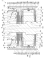
- FIG. 2 is a partial cross-sectional view showing the vicinity of the damping force generator of the shock absorber including the damping force generator of the first embodiment according to the present invention
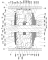
- 1 is a partial cross-sectional view showing the periphery of a main part of a damping force generator of a shock absorber including a damping force generator of a first embodiment according to the present invention
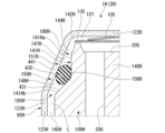
- FIG. FIG. 1 is a partial cross-sectional view showing the periphery of a main part of a damping force generator of a shock absorber including a damping force generator of a first embodiment according to the present invention
- FIG. 5 is a partial cross-sectional view showing the periphery of a main part of a damping force generator of a shock absorber including a damping force generator of a second embodiment according to the present invention
- FIG. 11 is a partial cross-sectional view showing the periphery of a main part of a damping force generator of a shock absorber including a damping force generator of a third embodiment according to the present invention
- FIG. 11 is a partial cross-sectional view showing the periphery of a main part of a damping force generating device for a shock absorber including a damping force generating device of a fourth embodiment according to the present invention
- FIG. 11 is a partial cross-sectional view showing the vicinity of a damping force generator of a shock absorber including a damping force generator of a fifth embodiment according to the present invention
- FIG. 11 is a partial cross-sectional view showing the vicinity of a damping force generator of a shock absorber including a damping force generator of a fifth embodiment according to the present invention
- FIG. 11 is a partial cross-sectional view showing a main part of a damping force generator for a shock absorber including a damping force generator of a sixth embodiment according to the present invention
- FIG. 11 is a partial cross-sectional view showing a main part of a damping force generating device for a shock absorber including a damping force generating device of a seventh embodiment according to the present invention
- FIG. 11 is a partial cross-sectional view showing the vicinity of a damping force generator of a shock absorber including a damping force generator of a fifth embodiment according to the present invention
- FIG. 11 is a partial cross-sectional
- FIG. 12 is a partial cross-sectional view showing a main part of a damping force generating device for a shock absorber including a damping force generating device of an eighth embodiment according to the present invention
- FIG. 20 is a partial cross-sectional view showing the main part of a damping force generator for a shock absorber including a damping force generator of a ninth embodiment according to the present invention
- FIG. 1 to 3 indicates the central axis of the damping force generator 1. As shown in FIG.
- a damping force generator 1 of the first embodiment is provided in a shock absorber 2.
- This shock absorber 2 is a shock absorber used for a suspension system of a railway vehicle, a two-wheeled vehicle, a four-wheeled vehicle, or the like.
- the shock absorber 2 is specifically a shock absorber used for a suspension system of a four-wheeled vehicle.
- the shock absorber 2 is a twin-tube shock absorber provided with a cylinder 5 having an inner cylinder 3 and an outer cylinder 4 .
- the inner cylinder 3 is a cylindrical member, specifically a cylindrical member.
- the outer cylinder 4 is a bottomed tubular member having a larger diameter than the inner cylinder 3 .
- the outer cylinder 4 is provided radially outwardly of the inner cylinder 3 and coaxially with the inner cylinder 3 .
- a reservoir chamber 6 is provided between the outer cylinder 4 and the inner cylinder 3 .
- the outer cylinder 4 has a body member 8 and a bottom member 9 .
- the body member 8 has a stepped cylindrical shape with both axial end sides having a smaller diameter than the axial intermediate portion.
- the bottom member 9 closes one axial end of the body member 8 .
- the side of the body member 8 opposite to the bottom member 9 is an opening.
- the shock absorber 2 includes a valve body 12 and a rod guide 13.
- the valve body 12 has an annular shape and is provided at one axial end of the inner cylinder 3 .
- the rod guide 13 has an annular shape and is provided at the other axial ends of the inner cylinder 3 and the outer cylinder 4 .
- the valve body 12 constitutes the base valve 15 and has a stepped outer peripheral portion. The large diameter portion of the valve body 12 is positioned on the bottom member 9 in the radial direction.
- the rod guide 13 also has a stepped outer peripheral portion.
- One axial end of the inner cylinder 3 is fitted to a small-diameter portion of the outer peripheral portion of the valve body 12 .
- One axial end of the inner cylinder 3 is placed on the bottom member 9 of the outer cylinder 4 via the valve body 12 .
- the other axial end of the inner cylinder 3 is fitted to the small-diameter portion of the outer circumference of the rod guide 13 .
- the other axial end of the inner cylinder 3 is fitted to the body member 8 of the outer cylinder 4 via the rod guide 13 .
- the inner cylinder 3 is radially positioned with respect to the outer cylinder 4 .
- the valve body 12 and the bottom member 9 communicate with the inner cylinder 3 and the outer cylinder 4 via a passage groove 16 formed in the valve body 12 .
- a reservoir chamber 6 is formed between the valve body 12 and the bottom member 9 in the same way as between the inner cylinder 3 and the outer cylinder 4 .
- the shock absorber 2 is provided with a sealing member 18.
- the sealing member 18 is provided on the opposite side of the rod guide 13 from the bottom member 9 .
- This seal member 18 is also fitted to the inner peripheral portion of the body member 8 in the same manner as the rod guide 13 .
- a locking portion 19 is formed at the end of the body member 8 opposite to the bottom member 9 .
- the locking portion 19 is formed by plastically deforming the body member 8 radially inward by crimping such as curling.
- the seal member 18 is sandwiched between the locking portion 19 and the rod guide 13 .
- the seal member 18 closes the opening of the outer cylinder 4, and is specifically an oil seal.
- the damping force generator 1 has a piston 21 (first regulating member).
- the piston 21 is slidably provided within the cylinder 5 .
- the piston 21 is slidably fitted in the inner cylinder 3 of the cylinder 5 .
- the piston 21 defines the interior of the inner cylinder 3 into an upper chamber 22 (first chamber) and a lower chamber 23 (second chamber).
- the upper chamber 22 is provided between the piston 21 and the rod guide 13 inside the inner cylinder 3 .
- the lower chamber 23 is provided between the piston 21 and the valve body 12 inside the inner cylinder 3 .
- the lower chamber 23 is defined as the reservoir chamber 6 by the valve body 12 .
- an upper chamber 22 and a lower chamber 23 are filled with an oil L as a working fluid.
- a reservoir chamber 6 in the cylinder 5 contains a gas G and an oil L as working fluids.
- the damping force generator 1 includes a piston rod 25 (shaft member). One axial end portion of the piston rod 25 is arranged inside the cylinder 5 and connected to the piston 21 . The other axial end portion of the piston rod 25 extends outside the cylinder 5 .
- the piston rod 25 is made of metal and extends through the upper chamber 22 .
- the piston rod 25 does not pass through the lower chamber 23. Therefore, the upper chamber 22 is a rod-side chamber through which the piston rod 25 passes.
- the lower chamber 23 is a bottom side chamber of the cylinder 5 on the side of the bottom member 9 .
- the piston 21 is fixed to a piston rod 25 and moves together with the piston rod 25 .
- Both the rod guide 13 and the seal member 18 are annular.
- the piston rod 25 is slidably inserted inside each of the rod guide 13 and the seal member 18 .
- the piston rod 25 extends from the inside of the cylinder 5 to the outside through the rod guide 13 and the seal member 18 .
- One axial end portion of the piston rod 25 is fixed to the piston 21 inside the cylinder 5 .
- the other axial end portion of the piston rod 25 extends outside the cylinder 5 via the rod guide 13 and the seal member 18 .
- the rod guide 13 supports the piston rod 25 with respect to the cylinder 5 so as to be axially movable while restricting its radial movement.
- the rod guide 13 guides the axial movement of the piston rod 25 .
- the outer circumference of the seal member 18 is in close contact with the inner circumference of the outer cylinder 4 of the cylinder 5 on the side of the opening of the body member 8 .
- the inner peripheral portion of the seal member 18 is in sliding contact with the outer peripheral portion of the piston rod 25 that moves in the axial direction. Thereby, the seal member 18 prevents the oil liquid L and the gas G in the cylinder 5 from leaking to the outside.
- the piston rod 25 has a main shaft portion 27 and a mounting shaft portion 28 .
- the mounting shaft portion 28 has an outer diameter smaller than that of the main shaft portion 27 .
- the main shaft portion 27 of the piston rod 25 is slidably fitted to the rod guide 13 and the seal member 18 .
- the piston rod 25 is connected to the piston 21 with a mounting shaft portion 28 disposed inside the cylinder 5 .
- An end portion of the main shaft portion 27 on the mounting shaft portion 28 side forms a shaft stepped portion 29 extending in the direction perpendicular to the axis.
- a passage cutout portion 30 is formed in the outer peripheral portion of the mounting shaft portion 28 .
- the passage cutout portion 30 is formed at an axially intermediate position of the mounting shaft portion 28 and extends in the axial direction of the mounting shaft portion 28 .
- the passage cutout portion 30 is formed, for example, by notching the outer peripheral portion of the attachment shaft portion 28 in a plane parallel to the center axis of the attachment shaft portion 28 .
- the passage cutouts 30 are formed at two locations that are 180 degrees apart in the circumferential direction of the attachment shaft 28 .
- a male thread 31 is formed on the outer peripheral portion of the mounting shaft portion 28 at a tip position on the side opposite to the main shaft portion 27 with respect to the passage cutout portion 30 in the axial direction.
- the mounting shaft portion 28 has a fitting shaft portion 32 except for the male thread 31 .
- the fitting shaft portion 32 has a columnar shape with a cylindrical outer peripheral surface.
- the passage cutout portion 30 is formed in an intermediate portion of the fitting shaft portion 32 in the axial direction.
- the twin-tube shock absorber 2 is supported by the vehicle body with the portion of the piston rod 25 protruding from the cylinder 5 arranged at the top in the vertical direction. At that time, the shock absorber 2 is connected to the wheel side with the bottom member 9 of the cylinder 5 arranged at the bottom in the vertical direction. In the case of a monotube shock absorber, on the contrary, it is also possible to have the cylinder 5 side supported by the vehicle body and the piston rod 25 connected to the wheel side.
- the piston 21 has a metal piston body 36 and a synthetic resin sliding member 37 .
- the piston body 36 is connected in contact with the piston rod 25 .
- the sliding member 37 is integrally attached to the outer peripheral surface of the piston body 36 .
- the piston 21 slides inside the inner tube 3 of the cylinder 5 with the sliding member 37 in contact with the inner tube 3 .
- the piston body 36 is provided with a plurality of passage holes 38 (only one location is shown because it is a cross section in FIG. 2) and a plurality of passage holes 39 (only one location is shown because it is a cross section in FIG. 2). there is Both the plurality of passage holes 38 and the plurality of passage holes 39 can communicate the upper chamber 22 and the lower chamber 23 .
- a plurality of passage holes 38 are arranged at equal pitches in the circumferential direction of the piston body 36 .
- the plurality of passage holes 38 are arranged in the circumferential direction of the piston body 36 with one passage hole 39 sandwiched therebetween.
- a plurality of passage holes 38 constitute half of the total number of passage holes 38 and 39 .
- the axial end of the piston 21 on the lower chamber 23 side opens radially inward of the piston 21 from the end on the upper chamber 22 side.
- An annular groove 55 is formed in the piston body 36 on the lower chamber 23 side in the axial direction. The annular groove 55 communicates with the passage holes 38 .
- the damping force generator 1 has a first damping force generating mechanism 41 on the lower chamber 23 side of the annular groove 55 .
- the first damping force generating mechanism 41 opens and closes passages in the plurality of passage holes 38 and the annular groove 55 to generate damping force.
- the passages in the plurality of passage holes 38 and the annular groove 55 move upstream in the movement of the piston 21 toward the upper chamber 22 side, that is, in the extension stroke.
- This is an extension-side passage through which the oil L flows from the upper chamber 22 on the side toward the lower chamber 23 on the downstream side.
- the first damping force generating mechanism 41 is provided for passages in the plurality of passage holes 38 on the extension side and in the annular groove 55 .
- the first damping force generating mechanism 41 generates a damping force by suppressing the flow of the oil L from the passages in the plurality of passage holes 38 and the annular groove 55 to the lower chamber 23 on the extension side. This is the generation mechanism.
- the plurality of passage holes 39 which constitute the remaining half of the total number of passage holes 38, 39, are arranged at equal pitches in the circumferential direction of the piston body 36.
- a plurality of passage holes 39 are arranged with one passage hole 38 therebetween.
- the end portion on the upper chamber 22 side in the axial direction of the piston 21 opens further inward in the radial direction of the piston 21 than the end portion on the lower chamber 23 side.
- An annular groove 56 is formed in the piston body 36 on the upper chamber 22 side in the axial direction. The annular groove 56 communicates the plurality of passage holes 39 .
- the damping force generator 1 has a first damping force generating mechanism 42 on the upper chamber 22 side of the annular groove 56 .
- the first damping force generating mechanism 42 opens and closes passages in the plurality of passage holes 39 and the annular groove 56 to generate damping force.
- the passages in the plurality of passage holes 39 and in the annular groove 56 move upstream in the movement of the piston 21 toward the lower chamber 23 side, that is, in the compression stroke. This is a contraction-side passage through which the oil L flows from the lower chamber 23 on the side toward the upper chamber 22 on the downstream side.
- the first damping force generating mechanism 42 is provided for passages in the plurality of passage holes 39 and the annular groove 56 on the compression side.
- the first damping force generating mechanism 42 suppresses the flow of the oil L from the passages in the plurality of passage holes 39 and the annular groove 56 on the compression side to the upper chamber 22 to generate a damping force on the compression side. This is the generation mechanism.
- the piston body 36 has a substantially disk shape, and an insertion hole 44 is formed in the center in the radial direction.
- the insertion hole 44 penetrates the piston body 36 in its axial direction.
- the mounting shaft portion 28 of the piston rod 25 is inserted into the insertion hole 44 .
- the insertion hole 44 has a small diameter hole portion 45 and a large diameter hole portion 46 .
- the small-diameter hole portion 45 is arranged on one side from the axial center of the insertion hole 44 .
- the large-diameter hole portion 46 is arranged on the other side of the insertion hole 44 from the center in the axial direction of the insertion hole 44 .
- the large-diameter hole portion 46 has an inner diameter larger than that of the small-diameter hole portion 45 .
- the piston body 36 has a small diameter hole portion 45 provided on the upper chamber 22 side in the axial direction, and a large diameter hole portion 46 provided on the lower chamber 23 side in the axial direction.
- the fitting shaft portion 32 of the piston rod 25 is fitted in the small diameter hole portion 45 of the piston 21 . Thereby, the piston 21 is radially positioned with respect to the piston rod 25 .
- An inner seat portion 47 and a valve seat portion 48 are formed at the axial end of the piston body 36 on the lower chamber 23 side.
- the inner seat portion 47 is arranged radially inward of the piston body 36 from the opening of the annular groove 55 on the lower chamber 23 side.
- the inner seat portion 47 is annular.
- the valve seat portion 48 is arranged radially outward of the piston body 36 from the opening of the annular groove 55 on the lower chamber 23 side.
- the valve seat portion 48 is annular.
- the valve seat portion 48 forms part of the first damping force generating mechanism 41 .
- An inner seat portion 49 and a valve seat portion 50 are formed at the axial end of the piston body 36 on the side of the upper chamber 22 .
- the inner seat portion 49 is arranged radially inward of the piston body 36 from the opening of the annular groove 56 on the side of the upper chamber 22 .
- the inner seat portion 49 has an annular shape.
- the valve seat portion 50 is arranged radially outward of the piston body 36 from the opening of the annular groove 56 on the side of the upper chamber 22 .
- the valve seat portion 50 has an annular shape.
- the valve seat portion 50 forms part of the first damping force generating mechanism 42 .
- the large-diameter hole portion 46 is provided closer to the inner seat portion 47 in the axial direction than the small-diameter hole portion 45 .
- the passage in the large-diameter hole portion 46 of the piston body 36 overlaps with the piston rod passage portion 51 in the passage notch portion 30 of the piston rod 25 in the axial direction.
- a passage in the large-diameter hole portion 46 always communicates with the piston rod passage portion 51 .
- the opening of the passage hole 39 on the contraction side on the lower chamber 23 side is arranged radially outward of the valve seat portion 48 .
- an opening on the upper chamber 22 side of the passage hole 38 extending radially outward of the valve seat portion 50 is arranged.
- the compression side first damping force generating mechanism 42 includes the valve seat portion 50 of the piston 21 .
- the first damping force generating mechanism 42 includes one disc 63, a plurality of (specifically two) discs 64, and a plurality of (specifically three) discs 64 in order from the piston 21 side in the axial direction.
- disk 65 a plurality of (specifically two) disks 66 , one disk 67 , one disk 68 , and one annular member 69 .
- the plurality of discs 64 have the same outer diameter.
- the plurality of discs 65 have the same outer diameter.
- the plurality of discs 66 have the same outer diameter.
- Each of the disks 63 to 68 and the annular member 69 is made of metal, and each has a perforated circular flat plate shape with a constant thickness and a constant radial width over the entire circumference.
- the discs 63 to 68 and the annular member 69 are radially positioned with respect to the piston rod 25 by fitting the fitting shaft portion 32 inside. All of the disks 63-68 are plain disks.
- a plain disk is a flat disk without axially projecting protrusions.
- the disc 63 has an outer diameter that is larger than the outer diameter of the inner seat portion 49 of the piston 21 and smaller than the inner diameter of the valve seat portion 50 .
- the disk 63 abuts the inner seat portion 49 .
- the plurality of discs 64 have the same outer diameter as the valve seat portion 50 of the piston 21 . Of the plurality of discs 64 , the disc 64 closest to the disc 63 can be seated on the valve seat portion 50 .
- the plurality of discs 65 have outer diameters smaller than the outer diameter of the discs 64 .
- the plurality of discs 66 has an outer diameter smaller than the outer diameter of the disc 65 .
- the disc 67 has an outer diameter smaller than the outer diameter of the disc 66 and slightly smaller than the outer diameter of the inner seat portion 49 of the piston 21 .
- the disc 68 has an outer diameter equal to that of the disc 65 .
- the annular member 69 has an outer diameter that is smaller than the outer diameter of the disk 68 and larger than the outer diameter of the shaft step portion 29 of the piston rod 25 .
- the annular member 69 is thicker and more rigid than the discs 63 to 68 and is in contact with the shaft stepped portion 29 .
- a plurality of discs 64 , a plurality of discs 65 and a plurality of discs 66 constitute a main valve 71 on the contraction side that can be seated and removed from the valve seat portion 50 .
- the main valve 71 allows passages in the plurality of passage holes 39 and in the annular groove 56 to communicate with the upper chamber 22 .
- the main valve 71 suppresses the flow of the oil L between the valve seat portion 50 and generates a damping force.
- the annular member 69 and the disk 68 abut against the main valve 71 to restrict the deformation of the main valve 71 in the opening direction beyond a specified limit.
- the passages in the plurality of passage holes 39 and the annular groove 56 and the passage between the main valve 71 and the valve seat portion 50 that appear when the valve is opened constitute a first passage 72 .
- the first passage 72 communicates the lower chamber 23 and the upper chamber 22 .
- the piston 21 has a first passage 72 that communicates the lower chamber 23 and the upper chamber 22 .
- Piston 21 defines this first passage 72 .
- the compression-side first damping force generating mechanism 42 that generates damping force includes a main valve 71 and a valve seat portion 50 . Therefore, the first damping force generating mechanism 42 is provided in this first passage 72 .
- the first passage 72 is provided in the piston 21 including the valve seat portion 50, and allows the oil L to pass therethrough when the piston rod 25 and the piston 21 move toward the contraction side.
- the first damping force generating mechanism 42 on the compression side no fixed orifice is formed in either the valve seat portion 50 or the main valve 71 that abuts thereon.
- the fixed orifice allows communication between the upper chamber 22 and the lower chamber 23 even when the valve seat portion 50 and the main valve 71 are in contact with each other. That is, the compression side first damping force generating mechanism 42 does not allow the upper chamber 22 and the lower chamber 23 to communicate with each other when the valve seat portion 50 and the main valve 71 are in contact with each other over the entire circumference.
- the first passage 72 is not provided with a fixed orifice that constantly communicates the upper chamber 22 and the lower chamber 23 .
- the first passage 72 is not a passage that always communicates between the upper chamber 22 and the lower chamber 23 .
- the extension-side first damping force generating mechanism 41 includes the valve seat portion 48 of the piston 21 .
- the first damping force generating mechanism 41 includes, in order from the piston 21 side in the axial direction, one disk 82, one disk 83, a plurality of (specifically three) disks 84, and one disk. It has a disk 85 , one disk 86 , one disk 87 , a plurality of (specifically three) disks 88 , and one disk 89 .
- the plurality of discs 84 have the same outer diameter.
- the plurality of discs 88 have the same outer diameter.
- the discs 82-89 are made of metal and have an annular shape.
- Each of the disks 83 to 89 is a perforated circular plate-shaped plain disk having a constant thickness and a constant radial width over the entire circumference.
- the discs 82 to 89 are radially positioned with respect to the piston rod 25 by fitting the fitting shaft portion 32 inside.
- the disc 82 has an outer diameter that is larger than the inner diameter of the inner seat portion 47 of the piston 21 and smaller than the inner diameter of the valve seat portion 48 .
- the disk 82 is in contact with the inner seat portion 47 .
- a notch portion 90 is formed in the disk 82 from an intermediate position outside the inner seat portion 47 in the radial direction to the inner peripheral edge portion.
- the notch 90 always communicates the passages in the annular groove 55 and the plurality of passage holes 38 with the passages in the large diameter hole portion 46 of the piston 21 and the piston rod passage portion 51 of the piston rod 25 .
- the notch 90 is formed when the disk 82 is press-molded.
- the disk 83 has the same outer diameter as the disk 82 and does not have a notch like the disk 82 does.
- the plurality of discs 84 have the same outer diameter as the valve seat portion 48 of the piston 21 .
- the disk 84 closest to the disk 83 among the plurality of disks 84 can be seated on the valve seat portion 48 .
- the disc 85 has an outer diameter smaller than that of the disc 84 .
- the disk 86 has an outer diameter similar to that of the disk 84 .
- the disc 87 has an outer diameter smaller than that of the disc 86 .
- the plurality of discs 88 have outer diameters smaller than the outer diameter of the disc 87 .
- the disc 89 has an outer diameter smaller than the outer diameter of the disc 88 and slightly larger than the outer diameter of the inner seat portion 47 of the piston 21 .
- a plurality of discs 84, a single disc 85, a single disc 86, a single disc 87, and a plurality of discs 88 constitute an extension-side main valve 91 that can be seated and removed from the valve seat portion 48.
- the main valve 91 allows passages in the annular groove 55 and in the plurality of passage holes 38 to communicate with the lower chamber 23 .
- the main valve 91 suppresses the flow of the oil L between the valve seat portion 48 and generates a damping force.
- the passages in the plurality of passage holes 38 and the annular groove 55, and the passage between the main valve 91 and the valve seat portion 48 appearing when the valve is opened constitute a first passage 92 (first flow passage).
- a first passage 92 is formed in the piston 21 .
- the first passage 92 communicates the upper chamber 22 and the lower chamber 23 .
- the piston 21 has a first passage 92 that communicates the upper chamber 22 and the lower chamber 23 .
- Piston 21 defines this first passage 92 .
- the first passage 92 is an extension side passage.
- the extension-side first damping force generating mechanism 41 that generates damping force includes a main valve 91 and a valve seat portion 48 . Therefore, the first damping force generating mechanism 41 is provided in this first passage 92 .
- the first passage 92 is provided in the piston 21 including the valve seat portion 48, and the oil L passes through it when the piston rod 25 and the piston 21 move to the extension side.
- neither the valve seat portion 48 nor the main valve 91 abutting thereon has a fixed orifice.
- the fixed orifice allows the upper chamber 22 and the lower chamber 23 to communicate with each other even when the valve seat portion 48 and the main valve 91 are in contact with each other. That is, the extension-side first damping force generating mechanism 41 does not allow the upper chamber 22 and the lower chamber 23 to communicate with each other when the valve seat portion 48 and the main valve 91 are in contact with each other over the entire circumference.
- the first passage 92 is not provided with a fixed orifice that constantly communicates the upper chamber 22 and the lower chamber 23 .
- the first passage 92 is not a passage that always communicates between the upper chamber 22 and the lower chamber 23 .
- the damping force generator 1 includes one case member 95, one spring member 105, and one spring member 105 in order from the disk 89 side on the side opposite to the piston 21 in the axial direction of the disk 89. It has one disk 106, one sub-valve 107, and one valve seat member 109 (second regulation member). The damping force generator 1 also has one O-ring 108 (elastic member) provided on the outer peripheral side of the valve seat member 109 .
- the damping force generator 1 includes one sub-valve 110, one disc 111, and one sub-valve 110, one disk 111, and one sub-valve 110, one disc 111, and one sub-valve 110, one disk 111, and one sub-valve 110, which is located on the side opposite to the sub-valve 107 in the axial direction of the valve seat member 109, in this order from the valve seat member 109 side. It has a spring member 112 , one disk 113 and one annular member 114 . Case member 95, spring members 105, 112, discs 106, 111, 113, sub-valves 107, 110 and valve seat member 109 have fitting shaft portion 32 of mounting shaft portion 28 of piston rod 25 fitted therein. ing.
- the annular member 114 has the male thread 31 of the mounting shaft portion 28 fitted therein. With these, the case member 95 , the spring members 105 and 112 , the discs 106 , 111 and 113 , the sub-valves 107 and 110 , the valve seat member 109 and the annular member 114 are radially positioned with respect to the piston rod 25 .
- the mounting shaft portion 28 of the piston rod 25 is formed with a male thread 31 at a portion that protrudes on the opposite side of the disk 113 from the annular member 114 in the axial direction.
- a nut 119 is screwed onto the male screw 31 .
- Nut 119 abuts annular member 114 .
- Annular members 69, 114, discs 63-68, 82-89, 106, 111, 113, piston 21, case member 95, spring members 105, 112, sub-valves 107, 110 and valve seat member 109 are each at least radially The inner peripheral side is axially clamped by the shaft step portion 29 of the piston rod 25 and the nut 119 . Therefore, the annular members 69, 114, the discs 63-68, 82-89, 106, 111, 113, the piston 21, the case member 95, the spring members 105, 112, the sub-valves 107, 110 and the valve seat member 109 are each at least The radially inner peripheral side is fixed to the piston rod 25 .
- case member 95 covers spring member 105 , disc 106 , sub-valve 107 , O-ring 108 and valve seat member 109 .
- Case member 95, spring members 105, 112, discs 106, 111, 113, sub-valves 107, 110, valve seat member 109 and annular member 114 are all made of metal.
- Each of the disks 106, 111, 113, the sub-valves 107, 110, and the annular member 114 is a perforated circular flat disk having a constant thickness and a constant radial width over the entire circumference.
- Both the case member 95 and the valve seat member 109 are annular with a constant radial width over the entire circumference.
- the spring members 105, 112 are annular.
- the case member 95 is an integrally molded product having a bottomed cylindrical shape, and is formed by, for example, plastic working or cutting of a metal plate.
- the case member 95 has a bottom portion 122 and a tubular portion 123 .
- the bottom portion 122 is in the form of a perforated disk of constant thickness.
- the tubular portion 123 extends from the outer peripheral edge of the bottom portion 122 along the axial direction of the bottom portion 122 .
- the tubular portion 123 is cylindrical.
- the bottom portion 122 has a perforated circular plate shape with a constant radial width over the entire circumference.
- the bottom portion 122 has an inner peripheral portion to which the fitting shaft portion 32 of the piston rod 25 is fitted.
- case member 95 is radially positioned and coaxially arranged with respect to the piston rod 25 .
- the case member 95 abuts the disk 89 with the bottom portion 122 located closer to the piston 21 than the cylindrical portion 123 in the axial direction.
- the case member 95 is thicker than one of the discs 84 to 88 and has a higher rigidity than the discs 84 to 88 in combination with its cylindrical shape with a bottom. Therefore, the case member 95 abuts on the main valve 91 and restricts deformation in the opening direction of the main valve 91 composed of the plurality of discs 84 to 88 beyond a specified limit.
- the spring member 105 has a substrate portion 127 and a plurality of spring plate portions 128 .
- the substrate portion 127 has a perforated circular plate shape with a constant radial width over the entire circumference.
- the substrate portion 127 has the fitting shaft portion 32 fitted to its inner peripheral portion. As a result, the substrate portion 127 is radially positioned and coaxially arranged with respect to the piston rod 25 .
- the plurality of spring plate portions 128 extend outward in the radial direction of the substrate portion 127 from equally spaced positions in the circumferential direction of the substrate portion 127 .
- the spring plate portion 128 is inclined with respect to the substrate portion 127 so as to separate from the substrate portion 127 in the axial direction of the substrate portion 127 toward the extension tip side.
- the base portion 127 of the spring member 105 contacts the bottom portion 122 of the case member 95 .
- the spring member 105 is attached to the attachment shaft portion 28 so that the spring plate portion 128 extends from the substrate portion 127 toward the sub-valve 107 in the axial direction of the substrate portion 127 .
- a plurality of spring plate portions 128 of the spring member 105 abut against the sub-valve 107 .
- the disc 106 has an outer diameter smaller than the outer diameter of the base portion 127 of the spring member 105 .
- a base portion 127 of the spring member 105 abuts against the disc 106 , and a plurality of spring plate portions 128 abut against the sub-valve 107 .
- the valve seat member 109 is in the shape of a perforated disc.
- a through hole 131 is formed in the radial center of the valve seat member 109 .
- the through hole 131 extends in the axial direction of the valve seat member 109 and penetrates the valve seat member 109 in the axial direction.
- the mounting shaft portion 28 of the piston rod 25 is inserted into the through hole 131 .
- the through hole 131 has a first hole portion 132 and a second hole portion 133 .
- the inner diameter of the second hole portion 133 is larger than the inner diameter of the first hole portion 132 .
- the first hole portion 132 is provided on one side of the through hole 131 in the axial direction of the through hole 131 .
- the second hole portion 133 is provided in the through hole 131 on the other side from the center in the axial direction of the through hole 131 .
- the fitting shaft portion 32 of the piston rod 25 is fitted into the first hole portion 132 .
- the valve seat member 109 is radially positioned and coaxially arranged with respect to the piston rod 25 .
- the valve seat member 109 has an inner seat portion 134 and a valve seat portion 135 at the axial end on the second hole portion 133 side.
- the inner seat portion 134 has an annular shape so as to surround the second hole portion 133 .
- the valve seat portion 135 extends radially outward from the inner seat portion 134 .
- the valve seat member 109 has an inner seat portion 138 and a valve seat portion 139 at the axially opposite end portion on the first hole portion 132 side.
- the inner seat portion 138 has an annular shape surrounding the first hole portion 132 .
- a valve seat portion 139 extends radially outward from this inner seat portion 138 .
- the valve seat member 109 has a body portion 140 between the inner seat portion 134 and the valve seat portion 135 and the inner seat portion 138 and the valve seat portion 139 in the axial direction.
- the body portion 140 is in the shape of a perforated disc.
- the inner sheet portion 134 protrudes to one side along the axial direction of the main body portion 140 from the inner peripheral edge portion of the end portion of the main body portion 140 on the second hole portion 133 side in the axial direction.
- the valve seat portion 135 protrudes from the body portion 140 to the same side as the inner seat portion 134 along the axial direction of the body portion 140 on the radially outer side of the inner seat portion 134 .
- the inner sheet portion 134 has a flat surface on the tip surface on the protruding side, ie, the tip surface on the side opposite to the main body portion 140 .
- the tip surface of the valve seat portion 135 on the projecting side that is, the tip surface on the side opposite to the body portion 140 is a flat surface.
- the tip surface of the inner seat portion 134 on the projecting side and the tip surface of the valve seat portion 135 on the projecting side spread in the direction orthogonal to the axis of the valve seat member 109 and are arranged on the same plane.
- the inner sheet portion 138 protrudes from the inner peripheral edge portion of the axial end of the main body portion 140 on the side of the first hole portion 132 along the axial direction of the main body portion 140 to the side opposite to the inner seat portion 134 .
- the valve seat portion 139 protrudes from the body portion 140 to the same side as the inner seat portion 138 along the axial direction of the body portion 140 on the radially outer side of the inner seat portion 138 .
- the inner sheet portion 138 has a flat surface on the tip surface on the protruding side, that is, the tip surface on the side opposite to the main body portion 140 .
- the tip surface of the valve seat portion 139 on the projecting side that is, the tip surface on the side opposite to the body portion 140 is a flat surface.
- the tip surface of the inner seat portion 138 on the projecting side and the tip surface of the valve seat portion 139 on the projecting side spread in the direction orthogonal to the axis of the valve seat member 109 and are arranged on the same plane
- the valve seat portion 135 is a deformed petal-shaped seat that is not circular.
- the valve seat portion 135 has a plurality of valve seat forming portions 201 .
- These valve seat components 201 have the same shape and are arranged at equal intervals in the circumferential direction of the valve seat member 109 .
- the inner seat portion 134 has an annular shape centered on the central axis of the valve seat member 109 .
- a plurality of valve seat forming portions 201 radially extend from the inner seat portion 134 .
- a passage concave portion 205 is formed inside each valve seat forming portion 201 .
- the passage recess 205 is formed by being surrounded by a portion of the inner seat portion 134 and the valve seat forming portion 201 .
- the passage recess 205 is recessed along the axial direction of the valve seat member 109 from the tip surface of the inner seat portion 134 on the protruding side and the tip surface of the valve seat forming portion 201 on the protruding side.
- a bottom surface of the passage concave portion 205 is formed by the main body portion 140 .
- a passage concave portion 205 is formed inside all the valve seat forming portions 201 .
- a passage hole 206 is formed at the central position of the passage concave portion 205 in the circumferential direction of the valve seat member 109 .
- the passage hole 206 axially penetrates the valve seat member 109 by axially penetrating the body portion 140 .
- the passage hole 206 is a straight hole parallel to the central axis of the valve seat member 109 .
- a passage hole 206 is formed in the bottom surface of all the passage recesses 205 .
- the valve seat portion 139 is also a non-circular petal-shaped deformed seat.
- the valve seat portion 139 has a plurality of valve seat forming portions 211 . These valve seat forming portions 211 have the same shape and are arranged at regular intervals in the circumferential direction of the valve seat member 109 .
- the inner seat portion 138 has an annular shape centered on the central axis of the valve seat member 109 .
- a plurality of valve seat forming portions 201 radially extend from the inner seat portion 138 .
- the valve seat forming portion 211 has the same shape as the valve seat forming portion 201 .
- a passage concave portion 215 is formed inside each valve seat forming portion 211 .
- the passage recess 215 is formed by being surrounded by a portion of the inner seat portion 138 and the valve seat forming portion 211 .
- the passage recess 215 is recessed along the axial direction of the valve seat member 109 from the tip surface of the inner seat portion 138 on the protruding side and the tip surface of the valve seat forming portion 211 on the protruding side.
- the bottom surface of passage recess 215 is formed by body portion 140 .
- a passage concave portion 215 is formed inside all the valve seat forming portions 211 .
- a passage hole 216 is formed at the central position of the passage concave portion 215 in the circumferential direction of the valve seat member 109 .
- the passage hole 216 axially penetrates the valve seat member 109 by axially penetrating the body portion 140 .
- the passage hole 216 is a straight hole parallel to the central axis of the valve seat member 109 .
- a passage hole 216 is formed in the bottom surface of all the passage recesses 215 .
- the circumferential arrangement pitch of the valve seat members 109 of the plurality of valve seat constituent portions 201 and the circumferential arrangement pitch of the valve seat members 109 of the plurality of valve seat constituent portions 211 are the same.
- the valve seat forming portion 201 and the valve seat forming portion 211 are displaced from each other by half the arrangement pitch in the circumferential direction of the valve seat member 109 .
- the passage hole 206 is arranged between the valve seat forming portions 211 adjacent to each other in the circumferential direction of the valve seat member 109 . Therefore, the passage hole 206 is arranged outside the range of the valve seat portion 139 .
- the passage hole 216 is arranged between the valve seat forming portions 201 adjacent to each other in the circumferential direction of the valve seat member 109 . Therefore, the passage hole 216 is arranged outside the range of the valve seat portion 135 .
- the valve seat member 109 has a passage groove 221 on the second hole portion 133 side in the axial direction.
- the passage groove 221 is formed in the inner seat portion 134 so as to cross the inner seat portion 134 in its radial direction.
- the passage groove 221 is recessed along the axial direction of the valve seat member 109 from the tip surface of the inner seat portion 134 opposite to the main body portion 140 .
- the passage groove 221 also includes a space between adjacent valve seat forming portions 201 in the circumferential direction of the valve seat member 109 .
- the passage hole 216 opens to the bottom surface of the passage groove 221 .
- a radial passage 222 in the passage groove 221 extends in the radial direction of the valve seat member 109 and allows the passage in the passage hole 216 and the passage in the second hole portion 133 to communicate with each other.
- a plurality of radial passages 222 are provided in the valve seat member 109 at equal intervals in the circumferential direction of the valve seat member 109 .
- a passage in the passage hole 216 and a passage in the passage concave portion 215 to which the passage hole 216 opens constitute a passage portion 161 provided in the valve seat member 109 .
- a plurality of passage portions 161 are provided in the valve seat member 109 at equal intervals in the circumferential direction of the valve seat member 109 .
- the passage portion 161 and the radial passage 222 communicate with each other.
- the valve seat member 109 has passage grooves 225 between adjacent valve seat forming portions 211 in the circumferential direction of the valve seat member 109 .
- the passage hole 206 opens to the bottom surface of the passage groove 225 . Therefore, the passage in passage groove 225 communicates with the passage in passage hole 206 .
- the passage hole 206 and the passage concave portion 205 to which the passage hole 206 opens form a passage portion 162 provided in the valve seat member 109 .
- a plurality of passage portions 162 are provided in the valve seat member 109 at regular intervals in the circumferential direction of the valve seat member 109 .
- the passage portion 162 communicates with the passage inside the passage groove 225 .
- a seal groove 141 is formed in the valve seat member 109 at the central position in the axial direction of the outer peripheral portion of the body portion 140 .
- the seal groove 141 has an annular shape and is recessed radially inward from the outer peripheral surface of the body portion 140 .
- the seal groove 141 has a bottom portion 141a arranged inside the valve seat member 109 in the radial direction, and a pair of side wall portions 141b arranged on both sides of the valve seat member 109 in the axial direction.
- the bottom portion 141 a has a groove bottom surface that faces outward in the radial direction of the valve seat member 109 and has a cylindrical surface along the axial direction of the valve seat member 109 .
- Wall surfaces of the pair of side wall portions 141b facing each other in the axial direction of the valve seat member 109 are flat and extend perpendicularly to the axial direction of the valve seat member 109 .
- An O-ring 108 is arranged in this seal groove 141 .
- the O-ring 108 is an elastic annular component made of rubber or the like.
- the O-ring 108 has an annular shape as a whole before being assembled to the valve seat member 109, and when the cross-section is taken along a plane including the central axis of the annular ring, the cross-section is circular.
- the valve seat member 109 is fitted to the tubular portion 123 of the case member 95 at the outer peripheral portion of the main body portion 140 with the inner seat portion 138 and the valve seat portion 139 facing away from the bottom portion 122 of the case member 95 . are combined.
- the O-ring 108 abuts against the inner peripheral surface of the cylindrical portion 123 of the case member 95 and the bottom surface of the bottom portion 141a at the deep end of the seal groove 141 of the valve seat member 109 in the recess direction, thereby closing the gap between them. is always sealed.
- the case member 95 and the valve seat member 109 have a case chamber 142 inside.
- the case chamber 142 is provided between the bottom portion 122 of the case member 95 and the valve seat member 109 .
- Spring member 105 , disc 106 and sub-valve 107 are provided within this case chamber 142 .
- the outer diameter of the portion of the body portion 140 of the valve seat member 109 excluding the seal groove 141 is smaller than the inner diameter of the cylindrical portion 123 of the case member 95 by a predetermined value.
- the valve seat member 109 is fitted to the fitting shaft portion 32 of the piston rod 25 so as to be radially positioned with respect to the mounting shaft portion 28 .
- the case member 95 is also fitted to the fitting shaft portion 32 of the piston rod 25 so as to be radially positioned with respect to the mounting shaft portion 28 . In this state, a gap is formed over the entire circumference between the outer peripheral surface of the body portion 140 excluding the seal groove 141 and the inner peripheral surface of the cylindrical portion 123 of the case member 95 .
- a passage portion 144 (third flow passage) is formed at a portion closer to the bottom portion 122 than the seal groove 141 in the axial direction of the valve seat member 109 .
- the passage portion 144 always communicates with the case chamber 142 .
- the portion of this gap on the opposite side of the bottom portion 122 from the seal groove 141 in the axial direction of the valve seat member 109 serves as a passage portion 145 (fourth flow passage).
- the passage portion 145 always communicates with the lower chamber 23 .
- the valve seat member 109 has a passage portion 144 and a passage portion 145 between itself and the case member 95 .
- the valve seat member 109 defines a passage portion 144 and a passage portion 145 together with the case member 95 .
- the width of the seal groove 141 in the axial direction that is, the distance between the wall surfaces of the pair of side wall portions 141b on both ends in the axial direction of the seal groove 141 is the same as the groove bottom surface of the bottom portion 141a of the seal groove 141 and the cylindrical shape. It is longer than the axial length of the O-ring 108 in contact with the inner peripheral surface of the portion 123 . Therefore, the O-ring 108 can move in the axial direction of the seal groove 141 within the seal groove 141 . During this movement, the O-ring 108 slides between the groove bottom surface of the bottom portion 141 a of the seal groove 141 and the inner peripheral surface of the cylindrical portion 123 .
- the inside of the seal groove 141 is divided by an O-ring 108 into a pressure accumulation chamber 147 (third chamber) and a pressure accumulation chamber 148 (fourth chamber).
- the pressure accumulating chamber 147 is provided closer to the bottom portion 122 than the O-ring 108 of the seal groove 141 in the axial direction of the valve seat member 109 .
- the pressure accumulation chamber 147 always communicates with the passage portion 144 .
- the pressure accumulation chamber 148 is provided on the opposite side of the O-ring 108 of the seal groove 141 from the bottom portion 122 in the axial direction of the valve seat member 109 .
- the pressure accumulation chamber 148 always communicates with the passage portion 145 . Communication between the pressure accumulation chambers 147 and 148 is always blocked by the O-ring 108 .
- the passage portion 144 communicates with the pressure accumulation chamber 147 which is either one of the pressure accumulation chamber 147 and the pressure accumulation chamber 148 .
- Passage portion 145 communicates with pressure accumulation chamber 148 , which is the other of pressure accumulation chamber 147 and pressure accumulation chamber 148 .
- the case member 95 and the valve seat member 109 have a passage portion 144 that communicates the case chamber 142 with the pressure accumulation chamber 147 .
- the case member 95 and the valve seat member 109 have a passage portion 145 that communicates the lower chamber 23 with the pressure accumulation chamber 148 .
- the inner peripheral portion of the cylindrical portion 123 of the case member 95 and the outer peripheral portion including the seal groove 141 of the body portion 140 of the valve seat member 109 constitute an outer shell portion 150 .
- the outer shell portion 150 is formed by the outer peripheral portion opposite to the piston rod 25 in the radial direction of the valve seat member 109 and the inner peripheral portion of the cylindrical portion 123 of the case member 95 .
- Outer shell portion 150 constitutes outer shells of pressure accumulation chamber 147 and pressure accumulation chamber 148 .
- Outer shell 150 houses O-ring 108 .
- the outer shell portion 150 is divided inside into a pressure accumulation chamber 147 and a pressure accumulation chamber 148 by an O-ring 108 .
- the annular valve seat member 109 and the bottomed cylindrical case member 95 are arranged in the lower chamber 23 which is one of the upper chamber 22 and the lower chamber 23 .
- the valve seat portion 139 of the valve seat member 109 is arranged on the lower chamber 23 side.
- the accumulator chamber 147 includes the passage portion 144 , the case chamber 142 , the radial passage 222 in the passage groove 221 of the valve seat member 109 , and the second hole portion 133 of the valve seat member 109 .
- the volumes of the pressure accumulation chambers 147 and 148 change.
- the O-ring 108, the pressure accumulation chamber 147, the pressure accumulation chamber 148, and the outer shell portion 150 constitute a pressure accumulation portion 151 provided with a variable volume.
- the accumulator chamber 147 increases in volume to allow the oil L to flow in from the upper chamber 22 .
- the volume of the pressure accumulating chamber 148 is reduced and the oil L is discharged to the lower chamber 23 side.
- the accumulator chamber 148 increases in volume to allow the oil L to flow in from the lower chamber 23 .
- the volume of the pressure accumulation chamber 147 is reduced and the oil L is discharged to the upper chamber 22 side.
- the pressure accumulating portion 151 prevents the sliding and deformation of the O-ring 108 from being hindered by the fluid L in the pressure accumulating chambers 147 and 148 .
- a plurality of passage grooves 225 of the valve seat member 109 are provided facing the lower chamber 23 .
- the plurality of passage portions 162 always communicate with the lower chamber 23 via passages in the plurality of passage grooves 225 .
- the sub-valve 107 is disc-shaped and has an outer diameter equal to the outer diameter of the tip surface of the valve seat portion 135 of the valve seat member 109 .
- the sub-valve 107 is always in contact with the inner seat portion 134 and can be seated and removed from the valve seat portion 135 .
- the sub-valve 107 closes all passages 162 by being seated on the entire valve seat portion 135 .
- the sub-valve 107 is seated on the entire valve seat forming portion 201 of the valve seat portion 135 to close the passage portion 162 inside the valve seat forming portion 201 .
- the spring member 105 urges the sub-valve 107 to contact the valve seat portion 135 of the valve seat member 109 .
- the sub-valve 107 is seated on the valve seat portion 135 by the biasing force of the spring member 105 to close the passage portion 162 .
- the sub-valve 107 that can be seated and removed from the valve seat portion 135 is provided inside the case chamber 142 .
- the sub-valve 107 is separated from the valve seat portion 135 within the case chamber 142 .
- the sub-valve 107 allows the plurality of passages 162 and the case chamber 142 to communicate with each other.
- the lower chamber 23 communicates with the upper chamber 22 .
- the sub-valve 107 suppresses the flow of the oil L between itself and the valve seat portion 135 to generate a damping force.
- the sub-valve 107 is an inflow valve that opens when the oil L flows from the lower chamber 23 to the upper chamber 22 side through the plurality of passages 162 .
- the sub-valve 107 is a check valve that regulates the outflow of the oil L from the upper chamber 22 to the lower chamber 23 through the passage portion 162 .
- the passage hole 216 forming the passage portion 161 opens outside the range of the valve seat portion 135 of the valve seat member 109 . Therefore, the passage hole 216 always communicates with the upper chamber 22 regardless of the sub-valve 107 seated on the valve seat portion 135 .
- the passages in the plurality of passage grooves 225 of the valve seat member 109 and the plurality of passage portions 162, the passages between the sub-valve 107 and the valve seat portion 135 appearing when the valve is opened, the case chamber 142, and the diameter of the valve seat member 109 The direction passage 222, the passage in the second hole portion 133 of the valve seat member 109, the piston rod passage portion 51 of the piston rod 25, the passage in the large diameter hole portion 46 of the piston 21, and the notch portion 90 of the disc 82.
- the inner passage and the passages in the annular groove 55 of the piston 21 and the plurality of passage holes 38 constitute the second passage 172 .
- the second passage 172 when the piston 21 moves toward the lower chamber 23, the oil L flows from the lower chamber 23 on the upstream side in the cylinder 5 to the upper chamber 22 on the downstream side. In the second passage 172, the oil L flows from the lower chamber 23 on the upstream side toward the upper chamber 22 on the downstream side during the movement of the piston 21 toward the lower chamber 23 side, that is, the compression stroke.
- the second passage 172 serves as a contraction-side passage.
- the second passage 172 on the contraction side is provided separately from the first passage 72 shown in FIG. 2 on the contraction side.
- the second passage 172 is provided entirely parallel to the first passage 72 .
- the bottom part 122 of the case member 95 is thicker than the sub-valve 107 and has high rigidity.
- the bottom portion 122 of the case member 95 abuts on the sub-valve 107 when the sub-valve 107 is deformed, thereby suppressing further deformation of the sub-valve 107 .
- the sub-valve 107 , the valve seat member 109 including the valve seat portion 135 , the disk 106 and the spring member 105 constitute a second damping force generating mechanism 173 .
- the second damping force generating mechanism 173 is provided on the piston rod 25 .
- the second damping force generating mechanism 173 is provided in the second passage 172 on the compression side.
- the second damping force generating mechanism 173 opens and closes the second passage 172 to suppress the flow of the oil L from the lower chamber 23 to the upper chamber 22 via the second passage 172 to generate a damping force.
- the second damping force generating mechanism 173 is a compression-side second damping force generating mechanism.
- the passage portion 145 is provided in parallel with the second damping force generating mechanism 173 on the compression side.
- the valve seat portion 135 of the second damping force generating mechanism 173 is provided on the valve seat member 109 .
- the second damping force generating mechanism 173 is arranged separately from the first damping force generating mechanism 42 that generates damping force in the same contraction stroke.
- the sub-valve 107 constituting the compression-side second damping force generating mechanism 173 is a compression-side sub-valve.
- the passage in the notch 90 of the disk 82 becomes the orifice 175 .
- the orifice 175 is arranged downstream of the sub-valve 107 in the flow of the oil L when the sub-valve 107 is opened and the oil L flows through the second passage 172 .
- the orifice 175 may be arranged upstream of the sub-valve 107 in the flow of the oil L when the sub-valve 107 is opened and the oil L flows through the second passage 172 .
- the orifice 175 is formed by notching the disk 82 of the first damping force generating mechanism 41 that contacts the piston 21 .
- neither the valve seat portion 135 nor the sub-valve 107 abutting thereon has a fixed orifice.
- the fixed orifice allows communication between the upper chamber 22 and the lower chamber 23 shown in FIG. 2 even when the valve seat portion 135 and the sub-valve 107 are in contact with each other. That is, the compression-side second damping force generating mechanism 173 does not allow the upper chamber 22 and the lower chamber 23 to communicate with each other when the valve seat portion 135 and the sub-valve 107 are in contact with each other.
- the second passage 172 does not have a fixed orifice that allows the upper chamber 22 and the lower chamber 23 to always communicate with each other.
- the second passage 172 is not a passage that always communicates between the upper chamber 22 and the lower chamber 23 .
- the second passage 172 on the contraction side that allows communication between the upper chamber 22 and the lower chamber 23 is arranged in parallel with the first passage 72 that is also on the contraction side and allows communication between the upper chamber 22 and the lower chamber 23. are doing.
- a first damping force generating mechanism 42 is provided in the first passage 72 .
- a second damping force generating mechanism 173 is provided in the second passage 172 . Therefore, both the first damping force generating mechanism 42 and the second damping force generating mechanism 173 on the compression side are arranged in parallel.
- the sub-valve 110 is disc-shaped and has an outer diameter equivalent to the outer diameter of the tip surface of the valve seat portion 139 of the valve seat member 109 .
- the sub-valve 110 is always in contact with the inner seat portion 138 and can be seated and removed from the valve seat portion 139 .
- the sub-valve 110 is seated on the entire valve seat portion 139 .
- the sub-valve 110 closes all the passages 161 .
- the sub-valve 110 is seated entirely on one of the valve seat forming portions 211 of the valve seat portion 139 .
- the sub-valve 110 closes the passage portion 161 inside the valve seat forming portion 211 .
- the sub-valve 110 can be a common component with the same shape as the sub-valve 107 .
- the disc 111 is a common component having the same shape as the disc 106.
- the outer diameter of the disk 111 is smaller than the outer diameter of the sub-valve 110 and smaller than the outer diameter of the inner seat portion 138 .
- the spring member 112 has a substrate portion 177 and a plurality of spring plate portions 178 .
- the substrate portion 177 has a perforated circular plate shape with a constant radial width over the entire circumference.
- the substrate portion 177 has the fitting shaft portion 32 fitted to its inner peripheral portion. As a result, the substrate portion 177 is radially positioned and coaxially arranged with respect to the piston rod 25 .
- the plurality of spring plate portions 178 extend outward in the radial direction of the substrate portion 177 from equally spaced positions in the circumferential direction of the substrate portion 177 .
- the spring plate portion 178 is inclined with respect to the substrate portion 177 so as to separate from the substrate portion 177 in the axial direction of the substrate portion 177 toward the extension tip side.
- Spring member 112 contacts disk 111 at substrate portion 177 .
- the spring member 112 is attached to the attachment shaft portion 28 so that the spring plate portion 178 extends from the substrate portion 177 toward the sub-valve 110 in the axial direction of the substrate portion 177 .
- a plurality of spring plate portions 178 of the spring member 112 abut against the sub-valve 110 .
- the spring member 112 urges the sub-valve 110 to contact the valve seat portion 139 of the valve seat member 109 .
- the sub-valve 110 is seated on the valve seat portion 139 by the biasing force of the spring member 112 to close the passage portion 161 .
- the sub-valve 110 is provided inside the lower chamber 23 .
- the sub-valve 110 allows communication between the upper chamber 22 and the pressure accumulation chamber 147 and the lower chamber 23 by being separated from the valve seat portion 139 .
- the sub-valve 110 suppresses the flow of the oil L between itself and the valve seat portion 139 to generate a damping force.
- the sub-valve 110 is a discharge valve that opens when the oil L is discharged from the upper chamber 22 and the pressure accumulation chamber 147 to the lower chamber 23 through the plurality of passages 161 of the valve seat member 109 .
- the sub-valve 110 is a check valve that regulates the inflow of the oil L from the lower chamber 23 into the upper chamber 22 and the pressure accumulation chamber 147 via the passage portion 161 .
- the passage hole 206 forming the passage portion 162 opens outside the range of the valve seat portion 139 in the valve seat member 109 . Therefore, the passage hole 206 always communicates with the lower chamber 23 regardless of the sub-valve 110 seated on the valve seat portion 139 .
- portion 51, a passage in the second hole portion 133 of the valve seat member 109, a radial passage 222 of the valve seat member 109, a case chamber 142, a plurality of passage portions 161 of the valve seat member 109, and when the valve is opened The appearing sub-valve 110 and the passage between the valve seat portion 139 constitute a second passage 182 (second flow path).
- the second passage 182 communicates the upper chamber 22 and the lower chamber 23 .
- the valve seat member 109 has a second passage 182 that communicates the upper chamber 22 and the lower chamber 23 .
- the valve seat member 109 defines this second passage 182 .
- the second passage 182 serves as an elongation-side passage through which the oil L flows from the upper chamber 22 on the upstream side toward the lower chamber 23 on the downstream side during the movement of the piston 21 toward the upper chamber 22 side, that is, the extension stroke. .
- the extension-side second passage 182 that allows communication between the upper chamber 22 and the lower chamber 23 is likewise an extension-side passage that allows communication between the upper chamber 22 and the lower chamber 23.
- 92 are parallel to each other except for passages in the annular groove 55 on the side of the upper chamber 22 and in the plurality of passage holes 38 .
- the second passageway 182 may be entirely parallel to the first passageway 92 . That is, at least a portion of the second passage 182 should be parallel to the first passage 92 .
- the passage portion 144 branches off from the second passage 182 and communicates with the pressure accumulation portion 151 .
- the disk 113 has an outer diameter equivalent to that of the sub-valve 110 .
- Disk 113 is thicker and stiffer than sub-valve 110 .
- the disk 113 abuts on the sub-valve 110 when the sub-valve 110 is deformed, and suppresses further deformation of the sub-valve 110 .
- the annular member 114 has an outer diameter smaller than the outer diameter of the disk 113 .
- the annular member 114 is a common component having the same shape as the annular member 69 .
- the sub valve 110 , the valve seat member 109 including the valve seat portion 139 , the discs 111 and 113 and the spring member 112 constitute a second damping force generating mechanism 183 .
- the second damping force generating mechanism 183 is provided in the extension side second passage 182 and opens and closes the second passage 182 .
- the second damping force generating mechanism 183 suppresses the flow of the oil L from the second passage 182 to the lower chamber 23 to generate damping force.
- the second damping force generating mechanism 183 is a rebound-side second damping force generating mechanism.
- the second damping force generating mechanism 183 is provided on the piston rod 25 and its valve seat portion 139 is provided on the valve seat member 109 .
- the second damping force generating mechanism 183 is arranged separately from the first damping force generating mechanism 41 that generates damping force in the same extension stroke.
- the sub-valve 110 that constitutes the extension-side second damping force generating mechanism 183 is an extension-side sub-valve.
- the passage portion 144 is provided in parallel with the extension-side second damping force generating mechanism 183 .
- the valve seat member 109 has a second passage 182 , passage portions 144 and 145 , and pressure accumulation chambers 147 and 148 .
- the O-ring 108 and the pressure accumulation chamber 148 constitute a lower chamber side volume variable mechanism 185 that changes the volume of the lower chamber 23 side by changing the volume of the pressure accumulation chamber 148 .
- the lower chamber-side variable volume mechanism 185 communicates with the contraction-side passage portion 145 .
- the O-ring 108 moves toward the bottom portion 122 in the axial direction of the valve seat member 109 or hits the wall surface of the side wall portion 141b on the side of the bottom portion 122 in the axial direction of the seal groove 141. When it contacts and is crushed, it changes so that the volume of the pressure accumulation chamber 148 may be increased.
- the O-ring 108 keeps the pressure accumulation chamber 148 and the pressure accumulation chamber 147 cut off.
- the lower chamber side volume varying mechanism 185 moves the O-ring 108 away from the bottom portion 122 in the axial direction of the valve seat member 109 or moves the side wall portion of the seal groove 141 on the opposite side to the bottom portion 122 in the axial direction.
- the volume of the pressure accumulation chamber 148 is changed so as to be reduced. Even in this case, the O-ring 108 keeps the pressure accumulation chamber 148 and the pressure accumulation chamber 147 cut off.
- the O-ring 108 and the accumulator chamber 147 constitute an upper chamber-side variable volume mechanism 186 .
- the upper chamber side volume variable mechanism 186 changes the volume of the upper chamber 22 side by changing the volume of the pressure accumulation chamber 147 .
- the upper chamber-side variable volume mechanism 186 communicates with the extension-side passage portion 144 .
- the upper chamber side volume varying mechanism 186 moves the O-ring 108 away from the bottom portion 122 in the axial direction of the valve seat member 109 or moves the side wall portion 141b on the side opposite to the bottom portion 122 in the axial direction of the seal groove 141. When it comes into contact with the wall surface and is crushed, the volume of the pressure accumulation chamber 147 is changed to increase.
- the O-ring 108 maintains the isolation state between the pressure accumulation chambers 147 and 148 .
- the upper chamber side volume varying mechanism 186 moves the O-ring 108 toward the bottom portion 122 in the axial direction of the valve seat member 109, or moves the wall surface of the side wall portion 141b on the side of the bottom portion 122 in the axial direction of the seal groove 141. , the volume of the pressure accumulation chamber 147 is reduced. Even in this case, the O-ring 108 maintains the isolation state between the pressure accumulation chambers 147 and 148 .
- the O-ring 108 is shared by the lower chamber side volume varying mechanism 185 and the upper chamber side volume varying mechanism 186 .
- a lower chamber-side variable volume mechanism 185 including the pressure accumulator 148 and an upper chamber-side variable volume mechanism 186 including the pressure accumulator 147 are provided in a pressure accumulator 151 that stores oil as a working fluid.
- the passage in the notch 90 of the disk 82 becomes the orifice 175 .
- the orifice 175 is common to the second passages 172,182.
- the orifice 175 is arranged upstream of the sub-valve 110 in the flow of the oil L when the sub-valve 110 opens and the oil L flows through the second passage 182 .
- the orifice 175 may be arranged downstream of the sub-valve 110 in the flow of the oil L when the sub-valve 110 opens and the oil L flows through the second passage 182 .
- the sub-valve 110 and the above-described sub-valve 107 are opened and closed independently.
- the extension-side second damping force generating mechanism 183 has no fixed orifice formed in either the valve seat portion 139 or the sub-valve 110 that abuts thereon.
- the fixed orifice allows communication between the upper chamber 22 and the lower chamber 23 even when the valve seat portion 139 and the sub-valve 110 are in contact with each other. That is, the extension-side second damping force generating mechanism 183 does not allow communication between the upper chamber 22 and the lower chamber 23 when the valve seat portion 139 and the sub-valve 110 are in contact with each other.
- the second passage 182 does not have a fixed orifice that allows the upper chamber 22 and the lower chamber 23 to always communicate with each other.
- the second passage 182 is not a passage that always communicates between the upper chamber 22 and the lower chamber 23 .
- the annular member 114 restricts the deformation of the sub-valve 110 in the opening direction beyond a specified limit by means of the disk 113 .
- the upper chamber 22 and the lower chamber 23 form the first damping force generating mechanisms 41 and 42 and the second damping force generating mechanism for the flow of the oil L in the axial direction within the range of the piston 21. Communication is only possible via 173,183.
- the shock absorber 2 is not provided with a fixed orifice that always communicates between the upper chamber 22 and the lower chamber 23 on the passage through which the oil L flows in the axial direction within the range of the piston 21 .
- the second passage 182 and the first passage 92 are arranged in parallel except for passages within the annular groove 55 and the plurality of passage holes 38 .
- the first damping force generating mechanism 41 and the second damping force generating mechanism 183 are provided in the first passage 92 and the second passage 182, respectively. Therefore, both the first damping force generating mechanism 41 and the second damping force generating mechanism 183 on the extension side are arranged in parallel.
- the case member 95 has a cylindrical shape with a bottom and is provided between the piston 21 and the valve seat member 109 in the second passages 172 and 182 .
- the valve seat member 109 is provided inside the case member 95 .
- the sub-valve 110 is provided on the lower chamber 23 side of the valve seat member 109 .
- the sub-valve 107 is provided within a case chamber 142 between the bottom portion 122 of the case member 95 and the valve seat member 109 .
- the inner peripheral side of the main valve 71 is clamped between the discs 63 and 67 while being assembled to the piston rod 25 .
- the main valve 71 abuts on the valve seat portion 50 of the piston 21 over the entire circumference.
- the inner peripheral side of the main valve 91 is clamped between the discs 83 and 89 .
- the main valve 91 abuts on the valve seat portion 48 of the piston 21 over the entire circumference.
- the sub-valve 107 is clamped on the inner peripheral side between the inner seat portion 134 of the valve seat member 109 and the disk 106 .
- the sub-valve 107 contacts the valve seat portion 135 of the valve seat member 109 over the entire circumference.
- the sub-valve 110 is clamped on the inner peripheral side between the inner seat portion 138 of the valve seat member 109 and the disc 111 .
- the sub-valve 110 contacts the valve seat portion 139 of the valve seat member 109 over the entire circumference.
- a liquid passage 251 and a liquid passage 252 are formed through the valve body 12 in the axial direction.
- the liquid passages 251 and 252 can communicate between the lower chamber 23 and the reservoir chamber 6 .
- the base valve 15 has a damping force generating mechanism 255 on the bottom member 9 side in the axial direction of the valve body 12 .
- the damping force generating mechanism 255 can open and close the liquid passage 251 .
- the damping force generation mechanism 255 is a compression side damping force generation mechanism.
- the base valve 15 also has a damping force generating mechanism 256 on the opposite side of the valve body 12 from the bottom member 9 in the axial direction.
- the damping force generating mechanism 256 can open and close the liquid passage 252 .
- the damping force generation mechanism 256 is a rebound damping force generation mechanism.
- the piston rod 25 moves to the compression side, and the piston 21 moves in the direction to narrow the lower chamber 23 .
- the base valve 15 causes the damping force generating mechanism 255 to open the liquid passage 251 and the oil L in the lower chamber 23 to the reservoir chamber. It will flow to 6.
- the damping force generating mechanism 255 generates a damping force at that time.
- the damping force generation mechanism 255 is a compression side damping force generation mechanism. The damping force generating mechanism 255 does not block the flow of the oil L in the liquid passage 252 .
- the piston rod 25 moves to the extension side, and the piston 21 moves in the direction to expand the lower chamber 23 .
- the base valve 15 causes the damping force generating mechanism 256 to open the fluid passage 252 to allow the oil L in the reservoir chamber 6 to flow into the lower chamber 23 .
- the damping force generating mechanism 256 generates a damping force.
- the damping force generation mechanism 256 is a rebound damping force generation mechanism.
- the damping force generating mechanism 256 does not block the flow of the oil L in the liquid passage 251 .
- the damping force generating mechanism 256 may be a suction valve that allows the oil L to flow from the reservoir chamber 6 into the lower chamber 23 without substantially generating a damping force.
- the rigidity is higher than that of 110 and the valve opening pressure is higher than that of sub-valve 110 . Therefore, in the extension stroke, the second damping force generating mechanism 183 is opened while the first damping force generating mechanism 41 is closed in an extremely low speed region in which the piston speed is lower than a predetermined value. In other words, the second damping force generating mechanism 183 opens to generate damping force when the piston speed is lower than that of the first damping force generating mechanism 41 . In the normal speed range where the piston speed is equal to or higher than this predetermined value, both the first damping force generating mechanism 41 and the second damping force generating mechanism 183 are opened.
- the sub-valve 110 is a very low speed valve that opens in a region where the piston speed is very low to generate a damping force.
- the pressure in the upper chamber 22 increases and the pressure in the lower chamber 23 decreases as the piston 21 moves toward the upper chamber 22 side.
- none of the first damping force generating mechanisms 41 and 42 and the second damping force generating mechanisms 173 and 183 has a fixed orifice that allows the upper chamber 22 and the lower chamber 23 to always communicate with each other. Therefore, the oil L in the upper chamber 22 flows through passages in the plurality of passage holes 38 of the piston 21 and the annular groove 55, passages in the orifice 175, passages in the large diameter hole portion 46 of the piston 21, and through the piston rod 25.
- the O-ring 108 increases the capacity of the pressure accumulation chamber 147 .
- the upper chamber-side variable volume mechanism 186 suppresses an increase in pressure in the accumulator chamber 147 .
- the lower chamber side volume varying mechanism 185 including the O-ring 108 reduces the volume of the pressure accumulation chamber 148 .
- the damping force generating mechanisms 41, 42 and the second damping force generating mechanisms 173, 183 has a fixed orifice that allows the upper chamber 22 and the lower chamber 23 to always communicate with each other. Therefore, the damping force rises sharply in the extension stroke when the piston speed is less than the first predetermined value at which the second damping force generating mechanism 183 opens.
- the first damping force generating mechanism 41 is closed when the piston speed is in a high speed region from the first predetermined value and in a very low speed region which is higher than the first predetermined value and lower than the second predetermined value.
- the second damping force generating mechanism 183 opens in this state.
- the sub-valve 110 is separated from the valve seat portion 139 to allow the upper chamber 22 and the lower chamber 23 to communicate with each other through the second passage 182 on the expansion side. Therefore, the oil L in the upper chamber 22 flows through passages in the plurality of passage holes 38 of the piston 21 and the annular groove 55, passages in the orifice 175, passages in the large diameter hole portion 46 of the piston 21, and through the piston rod 25.
- the first damping force generating mechanism 183 remains open while the second damping force generating mechanism 183 remains open. 41 opens. That is, the sub-valve 110 is separated from the valve seat portion 139 as described above, and the second passage 182 maintains the state in which the oil L flows from the upper chamber 22 to the lower chamber 23 through the second passage 182 on the extension side.
- An orifice 175 provided downstream of the valve 91 throttles the flow of the oil L.
- the pressure applied to the main valve 91 increases, the pressure difference increases, the main valve 91 is separated from the valve seat portion 48, and the oil flows from the upper chamber 22 to the lower chamber 23 through the first passage 92 on the extension side. Run the L. Therefore, the oil L in the upper chamber 22 flows into the lower chamber 23 through passages in the plurality of passage holes 38 and the annular groove 55 and passages between the main valve 91 and the valve seat portion 48 . That is, the oil L in the upper chamber 22 flows to the lower chamber 23 via the first passage 92 . As a result, even in the normal speed region where the piston speed is equal to or higher than the second predetermined value, a damping force with valve characteristics (the damping force is approximately proportional to the piston speed) can be obtained.
- the increase rate of the rebound damping force with respect to the increase in piston speed in the normal speed region is lower than the increase rate of the rebound damping force with respect to the increase in piston speed in the extremely low speed region.
- the slope of the increase rate of the damping force on the extension side with respect to the increase in the piston speed in the normal speed region can be flatter than in the extremely low speed region.
- the amount of oil L flowing from the upper chamber 22 to the accumulator chamber 147 is small. . Therefore, sliding and deformation of the O-ring 108 are small.
- the upper chamber side variable volume mechanism 186 can absorb the volume of the oil L flowing into the pressure accumulation chamber 147 due to the sliding and deformation of the O-ring 108 . Therefore, the pressure in the pressure accumulation chamber 147 is reduced. Therefore, when the extremely low-speed damping force rises, the state is as if the O-ring 108 were not present.
- the pressure accumulating chamber 147 can be in constant communication with the lower chamber 23, ie, the same state as when the second damping force generating mechanism 183 is absent. Therefore, in the elongation stroke at the time of high frequency input, the rise of the extremely low-speed damping force becomes gentler than at the time of low frequency input or in comparison with the conventional damping force characteristic.
- the damping force characteristics of the damping force generating mechanism 256 are also combined.
- the main valve 71 of the first damping force generating mechanism 42 has higher rigidity than the sub valve 107 of the second damping force generating mechanism 173.
- the valve opening pressure is higher than that of the sub-valve 107 . Therefore, in the compression stroke, the second damping force generating mechanism 173 is opened while the first damping force generating mechanism 42 is closed in a very low speed region in which the piston speed is lower than a predetermined value. In other words, the second damping force generating mechanism 173 opens to generate damping force when the piston speed is lower than that of the first damping force generating mechanism 42 .
- both the first damping force generating mechanism 42 and the second damping force generating mechanism 173 are opened.
- the sub-valve 107 is a very low speed valve that opens in a region where the piston speed is very low to generate a damping force.
- the pressure in the lower chamber 23 increases and the pressure in the upper chamber 22 decreases as the piston 21 moves toward the lower chamber 23 side.
- none of the first damping force generating mechanisms 41, 42 and the second damping force generating mechanisms 173, 183 has a fixed orifice that always communicates the lower chamber 23 and the upper chamber 22 with each other. Therefore, the oil L in the lower chamber 23 flows into the pressure accumulation chamber 148 through the passage portion 145 between the case member 95 and the valve seat member 109 . As a result, the pressure in the pressure accumulation chamber 148 is increased.
- the O-ring 108 moves to the bottom 122 side, or the side wall 141b of the seal groove 141 on the bottom 122 side is damaged. It hits the wall and collapses. As a result, the O-ring 108 increases the capacity of the pressure accumulation chamber 148 . As a result, the lower chamber-side variable volume mechanism 185 suppresses an increase in pressure in the accumulator chamber 148 . At this time, the upper chamber side volume variable mechanism 186 including the O-ring 108 reduces the volume of the pressure accumulation chamber 147 .
- the amount of inflow of the oil L from the lower chamber 23 to the accumulator chamber 148 as described above becomes large. Therefore, at the beginning of the contraction stroke, the O-ring 108 moves to its limit and collapses to its limit. After that, the O-ring 108 will not move or deform. As a result, the capacity of the pressure accumulation chamber 148 does not increase. As a result, the pressure in the second passage 172 increases to the point where the second damping force generating mechanism 173 opens.
- the damping force generating mechanisms 41, 42 and the second damping force generating mechanisms 173, 183 has a fixed orifice that always communicates the lower chamber 23 and the upper chamber 22 with each other. Therefore, the damping force rises sharply in the compression stroke when the piston speed is less than the third predetermined value at which the second damping force generating mechanism 173 opens.
- the first damping force generating mechanism 42 is closed when the piston speed is in a high speed region from the third predetermined value and in a very low speed region which is higher than the third predetermined value and lower than the fourth predetermined value.
- the second damping force generating mechanism 173 opens in this state.
- the sub-valve 107 is separated from the valve seat portion 135 to allow communication between the lower chamber 23 and the upper chamber 22 through the second passage 172 on the contraction side. Therefore, the oil L in the lower chamber 23 flows through the passage portion 162 in the valve seat member 109, the passage between the sub-valve 107 and the valve seat portion 135, the case chamber 142, and the radial direction passage 222 of the valve seat member 109. , the passage in the second hole portion 133 of the valve seat member 109, the piston rod passage portion 51 of the piston rod 25, the passage in the large diameter hole portion 46 of the piston 21, the orifice 175, and the annular groove 55 of the piston 21. and passages in the plurality of passage holes 38 into the upper chamber 22 .
- the first damping force generating mechanism 173 remains open while the second damping force generating mechanism 173 remains open. 42 is opened. That is, the sub-valve 107 is separated from the valve seat portion 135 as described above, and the sub-valve 107 in the second passage 172 remains in a state in which the oil L flows from the lower chamber 23 to the upper chamber 22 in the second passage 172 on the contraction side. An orifice 175 provided downstream of 107 throttles the flow of oil L.
- the pressure applied to the main valve 71 increases, the differential pressure increases, the main valve 71 is separated from the valve seat portion 50, and the oil flows from the lower chamber 23 to the upper chamber 22 through the first passage 72 on the contraction side. Run the L. Therefore, the oil L in the lower chamber 23 flows into the upper chamber 22 through passages in the plurality of passage holes 39 and the annular groove 56 and passages between the main valve 71 and the valve seat portion 50 . That is, the oil L in the lower chamber 23 flows into the upper chamber 22 via the first passage 72 . As a result, even in the normal speed region where the piston speed is equal to or higher than the fourth predetermined value, a damping force with valve characteristics (the damping force is approximately proportional to the piston speed) can be obtained.
- the increase rate of the compression damping force with respect to the increase in piston speed in the normal speed region is lower than the increase rate of the compression damping force with respect to the increase in piston speed in the extremely low speed region.
- the slope of the increase rate of the damping force on the extension side with respect to the increase in the piston speed in the normal speed region can be flatter than in the extremely low speed region.
- the accumulator chamber 148 is always in communication with the accumulator chamber 147, that is, the same state as the structure without the second damping force generating mechanism 173 can be achieved. Therefore, in the compression stroke at the time of high frequency input, the rise of the extremely low-speed damping force becomes gentler than at the time of low frequency input or in comparison with the conventional damping force characteristic.
- the contraction stroke of the shock absorber 2 the characteristics of the damping force generated by the damping force generating mechanism 255 are also combined.
- Patent Literature 1 described above describes a shock absorber having two valves that open in the same stroke.
- one valve is opened in a region where the piston speed is lower than the other valve, and both valves are opened in a region where the piston speed is higher than this.
- a valve can be opened.
- the damping force generator 1 of the first embodiment has a piston 21 that defines the interior of the cylinder 5 into an upper chamber 22 and a lower chamber 23, and has a first passage 92 that communicates the upper chamber 22 and the lower chamber 23. , and a valve seat member 109 having a second passage 182 which is provided so as to be at least partially parallel to the first passage 92 and communicates the upper chamber 22 and the lower chamber 23 .
- the valve seat member 109 is provided with a passage portion 144 that branches from the second passage 182 leading from the upper chamber 22 to the second damping force generating mechanism 183 and communicates with the pressure accumulation portion 151 .
- the pressure accumulator 151 makes the damping coefficient at stroke reversal dependent on the frequency, thereby significantly reducing the acceleration that occurs in the piston rod 25 at the time of stroke reversal, thereby suppressing the generation of abnormal noise that occurs at the time of stroke reversal. It becomes possible to
- the pressure accumulating portion 151 has an O-ring 108 which is an elastic member, and an outer shell portion 150 whose interior is defined by the O-ring 108 into pressure accumulating chambers 147 and 148. ing. Passage portion 144 communicates with pressure accumulation chamber 147 , which is one of pressure accumulation chamber 147 and pressure accumulation chamber 148 .
- the damping force generator 1 can improve the sealing performance between the pressure accumulation chambers 147 and 148 by using the O-ring 108 .
- the O-ring 108 forming the pressure accumulator 151 seals the gap between the case member 95 and the valve seat member 109, so that only one O-ring is required. Therefore, the number of parts can be reduced.
- the damping force generating device 1 also has a passage portion 145 through which the valve seat member 109 communicates the lower chamber 23 with the pressure accumulation chamber 148 which is the other of the pressure accumulation chambers 147 and 148 .
- the damping force generating device 1 can discharge the hydraulic fluid L from the pressure accumulation chamber 148 to the lower chamber 23 through the passage portion 145, the O-ring 108 slides when the hydraulic fluid L is introduced into the pressure accumulation chamber 147. The deformation becomes smoother, and the introduction of the oil L into the pressure accumulation chamber 147 becomes even smoother.
- the damping force generating device 1 can discharge the oil L from the pressure accumulation chamber 147 to the upper chamber 22 through the passage portion 144, when the oil L is introduced into the pressure accumulation chamber 148, the O-ring 108 slides and The deformation becomes smoother, and the introduction of the oil L into the pressure accumulation chamber 148 becomes even smoother. Further, the damping force generator 1 can immediately introduce the oil L in the lower chamber 23 into the pressure accumulating chamber 148 through the passage portion 145 when the stroke is reversed from the extension stroke to the compression stroke, and the O-ring 108 can be quickly removed. It can be restored to its original state.
- the damping force generator 1A of the second embodiment is partially different from the damping force generator 1.
- the shock absorber 2A differs from the shock absorber 2 in that the damping force generator 1 is replaced with a damping force generator 1A.
- the damping force generator 1A has a valve seat member 109A partially different from the valve seat member 109 instead of the valve seat member 109. As shown in FIG.
- a through hole 131A is formed in place of the through hole 131 in the valve seat member 109A.
- the through hole 131A is formed in the radial center of the valve seat member 109A.
- the through hole 131A extends in the axial direction of the valve seat member 109A and penetrates the valve seat member 109A in the axial direction.
- the mounting shaft portion 28 of the piston rod 25 is inserted into the through hole 131A.
- the through hole 131A has a first hole portion 132A, a second hole portion 133 similar to the through hole 131, and a seal groove 141A.
- the first hole portion 132A is arranged at the end of the through hole 131A opposite to the inner sheet portion 134 in the axial direction of the through hole 131A.
- the inner diameter of the first hole portion 132 ⁇ /b>A is the same as the inner diameter of the second hole portion 133 .
- the seal groove 141A is arranged between the second hole portion 133 and the first hole portion 132A in the axial direction of the through hole 131A.
- the seal groove 141A has an annular shape and is recessed radially outward of the valve seat member 109A from the first hole portion 132A and the second hole portion 133 .
- the seal groove 141A has a bottom portion 141Aa arranged radially outwardly of the valve seat member 109A, and a pair of side wall portions 141Ab arranged on both sides of the valve seat member 109A in the axial direction.
- the bottom portion 141Aa has a groove bottom surface that faces inward in the radial direction of the valve seat member 109A and has a cylindrical surface along the axial direction of the valve seat member 109A.
- the pair of side wall portions 141Ab have planar wall surfaces that face each other in the axial direction of the valve seat member 109A and extend perpendicularly to the axial direction of the valve seat member 109A.
- the through hole 131A has an inner diameter larger than the outer diameter of the fitting shaft portion 32 over the entire length.
- the valve seat member 109A has an inner seat portion 138A, which is partially different from the inner seat portion 138, instead of the inner seat portion 138.
- the inner seat portion 138A differs from the inner seat portion 138 in that a first hole portion 132A having an inner diameter larger than that of the first hole portion 132 is provided.
- a passage groove 281A is formed in the inner seat portion 138A.
- the passage groove 281A is recessed in the direction of the inner seat portion 134 from the tip surface of the inner seat portion 138A on the side opposite to the inner seat portion 134 in the axial direction of the valve seat member 109A.
- the passage groove 281A crosses the inner seat portion 138A in the radial direction of the inner seat portion 138A.
- the passage in passage groove 281A communicates with the passage in passage groove 225 .
- the valve seat member 109A has a body portion 140A that is partially different from the body portion 140 instead of the body portion 140. As shown in FIG.
- the body portion 140A has an outer diameter larger than that of the body portion 140 .
- the body portion 140 ⁇ /b>A is radially positioned with respect to the case member 95 by fitting into the cylindrical portion 123 of the case member 95 .
- a portion of the first hole portion 132A, a portion of the second hole portion 133, and the entire seal groove 141A are formed in the body portion 140A.
- the body portion 140A has a seal groove 282A that is axially longer than the seal groove 141 instead of the seal groove 141.
- the damping force generator 1A has an O-ring 285A instead of the O-ring 108.
- the O-ring 285A is arranged in this seal groove 282A.
- the O-ring 285A is also an elastic annular component such as rubber.
- the O-ring 285A has an annular shape as a whole before being assembled to the valve seat member 109A, and the cross-section of the O-ring 285A along a plane including the central axis of the annular ring has an elliptical shape.
- the valve seat member 109A is fitted to the cylindrical portion 123 of the case member 95 at the outer peripheral portion of the main body portion 140A with the inner seat portion 138A and the valve seat portion 139 facing the opposite side of the bottom portion 122 of the case member 95. are combined.
- the O-ring 285A abuts against the inner peripheral surface of the cylindrical portion 123 of the case member 95 and the bottom surface of the seal groove 282A of the valve seat member 109A at the deep end in the concave direction, thereby always sealing the gap between them. do.
- the O-ring 285A also abuts on the wall surfaces at both axial ends of the seal groove 282A.
- the damping force generator 1A has an O-ring 108A.
- the O-ring 108A is arranged in the seal groove 141A of the valve seat member 109A.
- the O-ring 108A is an elastic annular component made of rubber or the like.
- the O-ring 108A has an annular shape as a whole before being assembled to the valve seat member 109A, and when the cross-section of the O-ring 108A is taken along a plane including the central axis of the annular ring, the cross-section is circular.
- the O-ring 108A is in contact with the outer peripheral surface of the fitting shaft portion 32 of the piston rod 25 and the groove bottom surface of the bottom portion 141Aa at the deep end of the seal groove 141A of the valve seat member 109A in the recess direction, thereby always sealing the gap between them. .
- the inner diameters of the first hole portion 132A and the second hole portion 133 of the through hole 131A of the valve seat member 109A are larger than the outer diameter of the fitting shaft portion 32 of the piston rod 25 by a predetermined value.
- the valve seat member 109A is fitted to the tubular portion 123 of the case member 95 so as to be radially positioned with respect to the case member 95 .
- the case member 95 is radially positioned with respect to the piston rod 25 by being fitted to the fitting shaft portion 32 of the piston rod 25 . With these, the valve seat member 109A is radially positioned with respect to the piston rod 25. As shown in FIG.
- a gap is formed over the entire circumference between the inner peripheral surface of the first hole portion 132 ⁇ /b>A and the inner peripheral surface of the second hole portion 133 and the outer peripheral surface of the fitting shaft portion 32 .
- the portion on the bottom 122 side of the seal groove 141A in the axial direction of the valve seat member 109A, that is, the portion inside the second hole portion 133 serves as a passage portion 144A (third flow path).
- the passage portion 144A always communicates with the piston rod passage portion 51 .
- the portion opposite to the bottom portion 122 from the seal groove 141A in the axial direction of the valve seat member 109A, that is, the portion inside the first hole portion 132A serves as a passage portion 145A (fourth flow path).
- the passage portion 145A always communicates with the lower chamber 23 through the passage in the passage groove 281A and the passage in the passage groove 225.
- the valve seat member 109A has a passage portion 144A and a passage portion 145A between the piston rod 25 and the valve seat member 109A.
- the valve seat member 109A and the piston rod 25 define a passage portion 144A and a passage portion 145A.
- the width of the seal groove 141A in the axial direction is the same as the groove bottom surface of the bottom portion 141Aa of the seal groove 141A and the fitting shaft portion. 32 is longer than the axial length of the O-ring 108A in contact with the outer peripheral surface of the O-ring 108A. Therefore, the O-ring 108A can move in the axial direction of the seal groove 141A within the seal groove 141A. During this movement, the O-ring 108A slides between the groove bottom surface of the bottom portion 141Aa of the seal groove 141A and the outer peripheral surface of the fitting shaft portion 32. As shown in FIG.
- the seal groove 141A is partitioned into a pressure accumulation chamber 147A (third chamber) and a pressure accumulation chamber 148A (fourth chamber) by an O-ring 108A.
- the pressure accumulating chamber 147A is provided closer to the bottom portion 122 than the O-ring 108A of the seal groove 141A in the axial direction of the valve seat member 109A.
- the pressure accumulation chamber 147A always communicates with the passage portion 144A.
- the pressure accumulation chamber 148A is provided on the opposite side of the bottom portion 122 from the O-ring 108A of the seal groove 141A in the axial direction of the valve seat member 109A.
- the pressure accumulation chamber 148A always communicates with the passage portion 145A. Communication between the pressure accumulation chamber 147A and the pressure accumulation chamber 148A is always blocked by an O-ring 108A.
- the passage portion 144A communicates with the pressure accumulation chamber 147A, which is either one of the pressure accumulation chamber 147A and the pressure accumulation chamber 148A.
- the passage portion 145A communicates with the pressure accumulation chamber 148A, which is the other of the pressure accumulation chamber 147A and the pressure accumulation chamber 148A.
- the valve seat member 109A and the piston rod 25 have a passage portion 144A that communicates the upper chamber 22 (see FIG. 2) with the pressure accumulation chamber 147A.
- the valve seat member 109A and the piston rod 25 have a passage portion 145A that communicates the lower chamber 23 with the pressure accumulation chamber 148A.
- the outer peripheral portion of the fitting shaft portion 32 of the piston rod 25 and the inner peripheral portion including the seal groove 141A of the body portion 140A of the valve seat member 109A constitute the outer shell portion 150A.
- the outer shell portion 150A is formed by the inner peripheral portion on the piston rod 25 side in the radial direction of the valve seat member 109A and the outer peripheral portion of the fitting shaft portion 32 of the piston rod 25 .
- the outer shell portion 150A is provided between the valve seat member 109A and the fitting shaft portion 32 of the piston rod 25 inserted through the valve seat member 109A.
- the outer shell portion 150A constitutes outer shells of the pressure accumulation chamber 147A and the pressure accumulation chamber 148A. Outer shell 150A accommodates O-ring 108A.
- the outer shell portion 150A is divided inside into a pressure accumulation chamber 147A and a pressure accumulation chamber 148A by an O-ring 108A.
- the pressure accumulation chamber 147A is always in communication with the upper chamber 22 (see FIG. 2) via the passage portion 144A and the second passage 182. As shown in FIG. In other words, the passage portion 144A branches off from the second passage 182 and communicates with the pressure accumulation portion 151A.
- the volumes of the pressure accumulation chambers 147A and 148A change as the O-ring 108A moves or deforms in the axial direction within the seal groove 141A. That is, the O-ring 108A, the pressure accumulation chamber 147A, the pressure accumulation chamber 148A, and the outer shell portion 150A constitute a pressure accumulation portion 151A provided with a variable volume.
- the pressure accumulation chamber 147 ⁇ /b>A increases in volume to allow the oil L to flow from the upper chamber 22 . At this time, the volume of the pressure accumulation chamber 148A is reduced and the oil L is discharged to the lower chamber 23 side.
- the pressure accumulation chamber 148 ⁇ /b>A increases in volume to allow the oil L to flow in from the lower chamber 23 .
- the valve seat member 109A has a second passage 182, passage portions 144A and 145A, and pressure accumulation chambers 147A and 148A.
- the O-ring 108A and the pressure accumulation chamber 148A constitute a lower chamber side volume variable mechanism 185A that changes the volume of the lower chamber 23 side by changing the volume of the pressure accumulation chamber 148A.
- the lower chamber-side variable volume mechanism 185A communicates with the contraction-side passage portion 145A.
- the O-ring 108A moves toward the bottom portion 122 in the axial direction of the valve seat member 109A or hits the wall surface of the side wall portion 141Ab on the side of the bottom portion 122 in the axial direction of the seal groove 141A. When it contacts and is crushed, it changes so that the volume of 148 A of pressure accumulation chambers may be increased.
- the O-ring 108A maintains the state of disconnection between the pressure accumulation chamber 148A and the pressure accumulation chamber 147A.
- the lower chamber side volume varying mechanism 185A moves the O-ring 108A away from the bottom portion 122 in the axial direction of the valve seat member 109A, or the side wall portion of the seal groove 141A on the opposite side to the bottom portion 122 in the axial direction. If it abuts on the wall surface of 141Ab and is crushed, it changes so that the volume of 148 A of pressure accumulation chambers may be reduced. Even in this case, the O-ring 108A maintains the isolation state between the accumulator chamber 148A and the accumulator chamber 147A.
- the O-ring 108A and the accumulator chamber 147A constitute an upper chamber-side variable volume mechanism 186A.
- the upper chamber side volume variable mechanism 186A changes the volume of the upper chamber 22 (see FIG. 2) side by changing the volume of the pressure accumulation chamber 147A.
- the upper chamber-side variable volume mechanism 186A communicates with the extension-side passage portion 144A.
- the upper chamber side variable volume mechanism 186A moves the O-ring 108A away from the bottom portion 122 in the axial direction of the valve seat member 109A, or moves the side wall portion 141Ab on the side opposite to the bottom portion 122 in the axial direction of the seal groove 141A. When it comes into contact with the wall surface and is crushed, it changes so as to increase the volume of the pressure accumulation chamber 147A.
- the O-ring 108A maintains the state of disconnection between the accumulator chamber 147A and the accumulator chamber 148A.
- the upper chamber side volume varying mechanism 186A moves the O-ring 108A toward the bottom portion 122 in the axial direction of the valve seat member 109A, or moves the wall surface of the side wall portion 141Ab on the bottom portion 122 side in the axial direction of the seal groove 141A.
- the volume of the pressure accumulation chamber 147A is changed to be reduced. Even in this case, the O-ring 108A maintains the isolation state between the accumulator chamber 147A and the accumulator chamber 148A.
- the O-ring 108A is shared by the lower chamber side volume variation mechanism 185A and the upper chamber side volume variation mechanism 186A.
- a lower chamber side variable volume mechanism 185A including an accumulator chamber 148A and an upper chamber side volume varying mechanism 186A including a pressure accumulator chamber 147A are provided in a pressure accumulator portion 151A that stores hydraulic fluid as a working fluid.
- the pressure in the pressure accumulation chamber 147A is increased. Therefore, in the upper chamber side variable volume mechanism 186A, before the second damping force generating mechanism 183 is opened, the O-ring 108A moves to the opposite side of the bottom 122 or moves away from the bottom 122 of the seal groove 141A. It abuts against the wall surface of the side wall portion 141Ab on the opposite side and is crushed. Then, the O-ring 108A increases the capacity of the pressure accumulation chamber 147A. As a result, the upper chamber side variable volume mechanism 186A suppresses an increase in pressure in the pressure accumulation chamber 147A. At this time, the lower chamber side volume varying mechanism 185A including the O-ring 108A reduces the volume of the pressure accumulation chamber 148A.
- the amount of oil L flowing from the upper chamber 22 (see FIG. 2) to the pressure accumulation chamber 147A is large. Become. Therefore, at the beginning of the elongation process, the O-ring 108A moves to the limit and is crushed to the limit. Then, after that, the O-ring 108A neither moves nor deforms. As a result, the capacity of the pressure accumulation chamber 147A does not increase. As a result, the pressure in the second passage 182 rises to the point where the second damping force generating mechanism 183 opens.
- each of the first damping force generating mechanism 41, the first damping force generating mechanism 42 (see FIG. 2) and the second damping force generating mechanisms 173, 183 has an upper chamber 22 (see FIG. 2) and a lower chamber 23.
- the damping force rises sharply in the extension stroke when the piston speed is less than the first predetermined value at which the second damping force generating mechanism 183 opens.
- the first damping force generating mechanism 41 is closed when the piston speed is in a high speed region from the first predetermined value and in a very low speed region which is higher than the first predetermined value and lower than the second predetermined value.
- the second damping force generating mechanism 183 opens in this state.
- the sub-valve 110 is separated from the valve seat portion 139 to allow the upper chamber 22 (see FIG. 2) and the lower chamber 23 to communicate with each other through the second passage 182 on the extension side. Therefore, the oil L in the upper chamber 22 (see FIG. 2) flows to the lower chamber 23 via the second passage 182 .
- a damping force with valve characteristics (a characteristic in which the damping force is substantially proportional to the piston speed) can be obtained even in an extremely low speed range in which the piston speed is lower than the second predetermined value.
- the first damping force generating mechanism 183 remains open while the second damping force generating mechanism 183 remains open. 41 opens. That is, the sub-valve 110 is separated from the valve seat portion 139 as described above, and the oil L is allowed to flow from the upper chamber 22 (see FIG. 2) to the lower chamber 23 through the second passage 182 on the extension side.
- the valve 91 is separated from the valve seat portion 48, and the oil L flows from the upper chamber 22 (see FIG. 2) to the lower chamber 23 through the first passage 92 on the expansion side. Therefore, the oil L in the upper chamber 22 (see FIG.
- each of the first damping force generating mechanism 41, the first damping force generating mechanism 42 (see FIG. 2) and the second damping force generating mechanisms 173, 183 has a lower chamber 23 and an upper chamber 22 (see FIG. 2).
- the lower chamber side variable volume mechanism 185A causes the O-ring 108A to move to the bottom portion 122 side, or the side wall portion 141Ab of the seal groove 141A on the bottom portion 122 side to move. It hits the wall and collapses. Then, the O-ring 108A increases the capacity of the pressure accumulation chamber 148A. As a result, the lower chamber-side variable volume mechanism 185A suppresses an increase in pressure in the accumulator chamber 148A. At this time, the upper chamber side variable volume mechanism 186A including the O-ring 108A reduces the volume of the pressure accumulation chamber 147A.
- each of the first damping force generating mechanism 41, the first damping force generating mechanism 42 (see FIG. 2) and the second damping force generating mechanisms 173, 183 has a lower chamber 23 and an upper chamber 22 (see FIG. 2).
- the damping force rises sharply in the compression stroke when the piston speed is less than the third predetermined value at which the second damping force generating mechanism 173 opens.
- the first damping force generating mechanism 42 in the extremely low speed region where the piston speed is higher than the third predetermined value and lower than the fourth predetermined value that is higher than the third predetermined value, the first damping force generating mechanism 42 (see FIG. 2 ) is closed, the second damping force generating mechanism 173 is opened.
- the sub-valve 107 is separated from the valve seat portion 135 to allow communication between the lower chamber 23 and the upper chamber 22 (see FIG. 2) through the second passage 172 on the contraction side. Therefore, the oil L in the lower chamber 23 flows through the second passage 172 to the upper chamber 22 (see FIG. 2).
- a damping force with a valve characteristic (a characteristic in which the damping force is approximately proportional to the piston speed) can be obtained.
- the first damping force generating mechanism 173 remains open while the second damping force generating mechanism 173 remains open.
- 42 (see FIG. 2) is opened. That is, the sub-valve 107 is separated from the valve seat portion 135 as described above, and the main valve 107 is kept in a state in which the oil L flows from the lower chamber 23 to the upper chamber 22 (see FIG. 2) through the second passage 172 on the contraction side.
- the valve 71 (see FIG. 2) is separated from the valve seat portion 50 (see FIG. 2), and the oil L flows from the lower chamber 23 to the upper chamber 22 (see FIG.
- the damping force generator 1A of the second embodiment includes a second passage 182 which is provided so as to be at least partially parallel to the first passage 92 and which communicates between the upper chamber 22 (see FIG. 2) and the lower chamber 23. It has a valve seat member 109A.
- the valve seat member 109A is provided with a passage portion 144A branched from the second passage 182 leading from the upper chamber 22 to the second damping force generating mechanism 183 and communicated with the pressure accumulation portion 151A. Since the pressure accumulator 151A functions in the same manner as the pressure accumulator 151, the damping force generator 1A has the same effect as the damping force generator 1 does.
- the outer shell portion 150A is provided between the valve seat member 109A and the fitting shaft portion 32 of the piston rod 25 inserted through the valve seat member 109A.
- a dedicated part for forming 150A becomes unnecessary, and the number of parts can be reduced.
- the damping force generator 1B of the third embodiment is partially different from the damping force generator 1.
- the damper 2B differs from the damper 2 in that it has a damping force generator 1B instead of the damping force generator 1.
- FIG. The damping force generator 1B has a piston rod 25B, which is partially different from the piston rod 25, instead of the piston rod 25.
- the piston rod 25B has a mounting shaft portion 28B having a longer axial length than the mounting shaft portion 28 instead of the mounting shaft portion 28.
- the mounting shaft portion 28B has a fitting shaft portion 32B that is longer than the fitting shaft portion 32 in the axial direction. In place of the passage notch 30, the fitting shaft 32B has a passage notch 30B longer than the passage notch 30 in the axial direction of the fitting shaft 32B.
- the damping force generator 1B has a case member 95B that is partially different from the case member 95 instead of the case member 95.
- the case member 95B has a tubular portion 123B having a longer axial length than the tubular portion 123 instead of the tubular portion 123.
- the case member 95B has a bottom portion 122B that is partially different from the bottom portion 122 instead of the bottom portion 122.
- the bottom portion 122B differs from the bottom portion 122 in that a passage hole 291B is formed through the bottom portion 122B in the axial direction.
- a plurality of passage holes 291B are provided in the bottom portion 122B at equal intervals in the circumferential direction of the bottom portion 122B.
- the passage hole 291B is arranged outside the outer end of the disk 89 in the radial direction of the bottom portion 122B.
- the damping force generator 1B has a valve seat member 109B, which is partially different from the valve seat member 109, instead of the valve seat member 109.
- the valve seat member 109B has a body portion 140B that is partially different from the body portion 140 instead of the body portion 140.
- the main body portion 140B has an outer diameter larger than that of the main body portion 140 .
- the body portion 140B has a seal groove 282A similar to that of the second embodiment.
- the damping force generator 1B has an O-ring 285A similar to that of the second embodiment.
- the valve seat member 109B is fitted to the cylindrical portion 123B of the case member 95B at the outer peripheral portion of the main body portion 140B with the inner seat portion 138 and the valve seat portion 139 facing away from the bottom portion 122B of the case member 95B. are combined.
- the O-ring 285A abuts against the inner peripheral surface of the cylindrical portion 123B of the case member 95B, the groove bottom surface of the seal groove 282A of the valve seat member 109B, and the wall surfaces at both axial ends of the seal groove 282A.
- the damping force generator 1B is provided with a chamber forming member 295B (second defining member) between the bottom portion 122B of the case member 95B and the spring member 105 in the axial direction of the piston rod 25B.
- the chamber forming member 295B is made of metal and has a perforated disc shape with a constant radial width over the entire circumference.
- the chamber forming member 295B has an outer diameter smaller than the inner diameter of the tubular portion 123B of the case member 95B.
- the chamber forming member 295B is radially positioned with respect to the piston rod 25B by fitting the fitting shaft portion 32B inside.
- the chamber forming member 295B is clamped to the bottom portion 122B of the case member 95B and the base portion 127 of the spring member 105 in the axial direction of the piston rod 25B.
- the chamber forming member 295B has a stepped portion 296B on its outer peripheral side.
- the stepped portion 296B has an annular shape and is recessed in the axial direction of the chamber forming member 295B from the end face on one axial side of the chamber forming member 295B.
- the stepped portion 296B extends to the radially outer end surface of the chamber forming member 295B.
- the chamber forming member 295B has a smaller thickness in the axial direction at the portion where the stepped portion 296B is formed than at the portion inside the stepped portion 296B in the radial direction. In the radial direction of the chamber forming member 295B, the stepped portion 296B is aligned with the passage hole 291B of the case member 95B.
- a seal groove 141B is formed in the chamber forming member 295B within the range of the stepped portion 296B in the radial direction thereof.
- the seal groove 141B has an annular shape and is recessed in the axial direction of the chamber forming member 295B from one axial end surface of the stepped portion 296B. In the radial direction of the chamber forming member 295B, the entire seal groove 141B is arranged outside the passage hole 291B of the case member 95B.
- the O-ring 108B is arranged in this seal groove 141B.
- the O-ring 108B is an elastic annular component made of rubber or the like.
- the O-ring 108B has an annular shape as a whole before being assembled to the chamber forming member 295B, and when the cross-section of the O-ring 108B is taken along a plane including the central axis of the annular ring, the cross-section is circular.
- the chamber forming member 295B is fitted to the fitting shaft portion 32B with the stepped portion 296B directed toward the bottom portion 122 of the case member 95B.
- the chamber forming member 295B contacts the bottom portion 122B at the inner end surface of the stepped portion 296B in the radial direction.
- the O-ring 108B provided in the seal groove 141B is located between the inner end surface of the bottom portion 122B of the case member 95B in the axial direction on the side of the cylindrical portion 123B and the inner end of the chamber forming member 295B in the recess direction of the seal groove 141B. These gaps are always sealed by coming into contact with the bottom surface of the groove.
- the chamber forming member 295B abuts on the base portion 127 of the spring member 105 at its axial end face opposite to the bottom portion 122B.
- the chamber forming member 295B forms a case chamber 142 between itself and the valve seat member 109B in the axial direction.
- a gap is formed over the entire circumference between the stepped portion 296B and the inner end face of the bottom portion 122B of the case member 95B.
- a passage portion 144B (third flow path) is formed outside the seal groove 141B in the radial direction of the chamber forming member 295B.
- the passage portion 144B always communicates with the case chamber 142 .
- a portion inside the seal groove 141B in the radial direction of the chamber forming member 295B serves as a passage portion 145B (fourth flow path).
- the passage portion 145B always communicates with the lower chamber 23 through the passage in the passage hole 291B of the case member 95B.
- the chamber forming member 295B has a passage portion 144B and a passage portion 145B between it and the case member 95B.
- the chamber forming member 295B defines the passage portion 144B and the passage portion 145B together with the case member 95B.
- the radial width of the seal groove 141B that is, the distance between the wall surfaces at both radial ends of the seal groove 141B is the distance between the wall surfaces of the seal groove 141B and the groove bottom surface of the seal groove 141B and the inner end surface of the bottom portion 122B. It is longer than half the difference between the outer diameter and the inner diameter of O-ring 108B. Therefore, the O-ring 108B can move in the radial direction of the seal groove 141B within the seal groove 141B. During this movement, the O-ring 108B slides between the groove bottom surface of the seal groove 141B and the inner end surface of the bottom portion 122B.
- the inside of the seal groove 141B is partitioned into a pressure accumulation chamber 147B (third chamber) and a pressure accumulation chamber 148B (fourth chamber) by an O-ring 108B.
- the pressure accumulation chamber 147B is provided outside the O-ring 108B of the seal groove 141B in the radial direction of the chamber forming member 295B.
- the pressure accumulation chamber 147B always communicates with the passage portion 144B.
- the pressure accumulation chamber 148B is provided inside the O-ring 108B of the seal groove 141B in the radial direction of the chamber forming member 295B.
- the pressure accumulation chamber 148B always communicates with the passage portion 145B. Communication between the pressure accumulation chamber 147B and the pressure accumulation chamber 148B is always blocked by the O-ring 108B.
- the passage portion 144B communicates with the pressure accumulation chamber 147B, which is either one of the pressure accumulation chamber 147B and the pressure accumulation chamber 148B.
- Passage portion 145B communicates with pressure accumulation chamber 148B, which is the other of pressure accumulation chamber 147B and pressure accumulation chamber 148B.
- the case member 95B and the chamber forming member 295B have a passage portion 144B communicating with the upper chamber 22 (see FIG. 2).
- the case member 95B and the chamber forming member 295B have a passage portion 145B that communicates the lower chamber 23 with the pressure accumulation chamber 148B.
- the inner end surface side portion of the bottom portion 122B of the case member 95B and the stepped portion 296B including the seal groove 141B of the chamber forming member 295B constitute the outer shell portion 150B.
- the outer shell portion 150B constitutes outer shells of the pressure accumulation chamber 147B and the pressure accumulation chamber 148B. Outer shell 150B accommodates O-ring 108B.
- the outer shell portion 150B is divided inside into a pressure accumulation chamber 147B and a pressure accumulation chamber 148B by an O-ring 108B.
- the pressure accumulation chamber 147B is always in communication with the upper chamber 22 (see FIG. 2) via the passage portion 144B and the second passage 182. As shown in FIG.
- the volumes of the pressure accumulation chambers 147B and 148B change. That is, the O-ring 108B, the pressure accumulation chamber 147B, the pressure accumulation chamber 148B, and the outer shell portion 150B constitute a pressure accumulation portion 151B provided with a variable volume.
- the pressure accumulation chamber 147B increases in volume to allow the oil L to flow from the upper chamber 22 (see FIG. 2). At this time, the volume of the pressure accumulation chamber 148B is reduced and the oil L is discharged to the lower chamber 23 side.
- the accumulator chamber 148 ⁇ /b>B increases in volume to allow the oil L to flow from the lower chamber 23 .
- the chamber forming member 295B has a second passage 182, passage portions 144B and 145B, and pressure accumulation chambers 147B and 148B between itself and the case member 95B.
- the passage portion 144B branches from the second passage 182 and communicates with the pressure accumulation portion 151B.
- the O-ring 108B and the pressure accumulation chamber 148B constitute a lower chamber side volume variable mechanism 185B that changes the volume of the lower chamber 23 side by changing the volume of the pressure accumulation chamber 148B.
- the lower chamber-side variable volume mechanism 185B communicates with the contraction-side passage portion 145B.
- the lower chamber-side variable volume mechanism 185B changes the pressure in the accumulator chamber 148B. change to increase the volume of At this time, the O-ring 108B maintains the isolation state between the pressure accumulation chamber 148B and the pressure accumulation chamber 147B.
- the lower chamber-side volume varying mechanism 185B will move to the accumulator. Change to reduce the volume of 148B. Even in this case, the O-ring 108B maintains the blocked state between the pressure accumulation chamber 148B and the pressure accumulation chamber 147B.
- the O-ring 108B and the accumulator chamber 147B constitute an upper chamber-side variable volume mechanism 186B.
- the upper chamber side volume variable mechanism 186B changes the volume of the upper chamber 22 (see FIG. 2) side by changing the volume of the pressure accumulation chamber 147B.
- the upper chamber-side variable volume mechanism 186B communicates with the extension-side passage portion 144B.
- the O-ring 108B maintains the isolation state between the pressure accumulation chambers 147B and 148B.
- the upper chamber-side variable volume mechanism 186B will be deformed. Change to reduce the volume of 147B. Even in this case, the O-ring 108B maintains the blocked state between the pressure accumulation chambers 147B and 148B.
- the O-ring 108B is shared by the lower chamber side volume variation mechanism 185B and the upper chamber side volume variation mechanism 186B.
- a lower chamber-side variable volume mechanism 185B including a pressure accumulator 148B and an upper chamber-side variable volume mechanism 186B including a pressure accumulator 147B are provided in a pressure accumulator 151B that stores oil L as working fluid.
- the pressure in the pressure accumulation chamber 147B is increased. Therefore, in the upper chamber side variable volume mechanism 186B, before the second damping force generating mechanism 183 is opened, the O-ring 108B is deformed while moving radially inward, or the seal groove 141B is deformed radially inward. It hits the wall and collapses. Then, the O-ring 108B increases the capacity of the pressure accumulation chamber 147B. As a result, the upper chamber-side variable volume mechanism 186B suppresses an increase in pressure in the pressure accumulation chamber 147B. At this time, the lower chamber side volume varying mechanism 185B including the O-ring 108B reduces the volume of the pressure accumulation chamber 148B.
- the amount of oil L flowing from the upper chamber 22 (see FIG. 2) to the pressure accumulation chamber 147B is large. Become. For this reason, the O-ring 108B is deformed and crushed to near the limit in the initial stage of the elongation process. After that, the O-ring 108B is no longer deformed. As a result, the capacity of the pressure accumulation chamber 147B does not increase. As a result, the pressure in the second passage 182 rises to the point where the second damping force generating mechanism 183 opens.
- each of the first damping force generating mechanism 41, the first damping force generating mechanism 42 (see FIG. 2) and the second damping force generating mechanisms 173, 183 has an upper chamber 22 (see FIG. 2) and a lower chamber 23.
- the damping force rises sharply in the extension stroke when the piston speed is less than the first predetermined value at which the second damping force generating mechanism 183 opens.
- the first damping force generating mechanism 41 is closed when the piston speed is in a high speed region from the first predetermined value and in a very low speed region which is higher than the first predetermined value and lower than the second predetermined value.
- the second damping force generating mechanism 183 opens in this state.
- the sub-valve 110 is separated from the valve seat portion 139 to allow the upper chamber 22 (see FIG. 2) and the lower chamber 23 to communicate with each other through the second passage 182 on the extension side. Therefore, the oil L in the upper chamber 22 (see FIG. 2) flows to the lower chamber 23 via the second passage 182 .
- a damping force with valve characteristics (a characteristic in which the damping force is substantially proportional to the piston speed) can be obtained even in an extremely low speed range in which the piston speed is lower than the second predetermined value.
- the first damping force generating mechanism 183 remains open while the second damping force generating mechanism 183 remains open. 41 opens. That is, the sub-valve 110 is separated from the valve seat portion 139 as described above, and the oil L is allowed to flow from the upper chamber 22 (see FIG. 2) to the lower chamber 23 through the second passage 182 on the extension side.
- the valve 91 is separated from the valve seat portion 48, and the oil L flows from the upper chamber 22 (see FIG. 2) to the lower chamber 23 through the first passage 92 on the expansion side. Therefore, the oil L in the upper chamber 22 (see FIG.
- each of the first damping force generating mechanism 41, the first damping force generating mechanism 42 (see FIG. 2) and the second damping force generating mechanisms 173, 183 has a lower chamber 23 and an upper chamber 22 (see FIG. 2).
- the lower chamber side variable volume mechanism 185B deforms while the O-ring 108B moves radially outward, or the radially outer wall surface of the seal groove 141B is deformed. or crushed by coming into contact with Then, the O-ring 108B increases the capacity of the pressure accumulation chamber 148B. As a result, the lower chamber-side variable volume mechanism 185B suppresses an increase in pressure in the pressure accumulation chamber 148B. At this time, the upper chamber side variable volume mechanism 186B including the O-ring 108B reduces the volume of the pressure accumulation chamber 147B.
- the amount of the oil L flowing from the lower chamber 23 to the pressure accumulation chamber 148B as described above becomes large. Therefore, the O-ring 108B is deformed and crushed to near the limit at the beginning of the contraction stroke. After that, the O-ring 108B is no longer deformed. As a result, the capacity of the pressure accumulation chamber 148B does not increase. As a result, the pressure in the second passage 172 increases until the second damping force generating mechanism 173 opens.
- each of the first damping force generating mechanism 41, the first damping force generating mechanism 42 (see FIG. 2) and the second damping force generating mechanisms 173, 183 has a lower chamber 23 and an upper chamber 22 (see FIG. 2).
- the damping force rises sharply in the compression stroke when the piston speed is less than the third predetermined value at which the second damping force generating mechanism 173 opens.
- the first damping force generating mechanism 42 opens the second damping force generating mechanism 173 while the valve is closed.
- the sub-valve 107 is separated from the valve seat portion 135 to allow communication between the lower chamber 23 and the upper chamber 22 (see FIG. 2) through the second passage 172 on the contraction side. Therefore, the oil L in the lower chamber 23 flows through the second passage 172 to the upper chamber 22 (see FIG. 2).
- a damping force with a valve characteristic (a characteristic in which the damping force is approximately proportional to the piston speed) can be obtained.
- the first damping force generating mechanism 173 remains open while the second damping force generating mechanism 173 remains open.
- 42 (see FIG. 2) is opened. That is, the sub-valve 107 is separated from the valve seat portion 135 as described above, and the main valve 107 is kept in a state in which the oil L flows from the lower chamber 23 to the upper chamber 22 (see FIG. 2) through the second passage 172 on the contraction side.
- the valve 71 (see FIG. 2) is separated from the valve seat portion 50 (see FIG. 2), and the oil L flows from the lower chamber 23 to the upper chamber 22 (see FIG.
- the damping force generator 1B of the third embodiment includes a second passage 182 which is provided so as to be at least partially parallel to the first passage 92 and which communicates between the upper chamber 22 (see FIG. 2) and the lower chamber 23. It has a chamber forming member 295B. Further, the chamber forming member 295B is provided with a passage portion 144B that branches from the second passage 182 leading from the upper chamber 22 to the second damping force generating mechanism 183 and communicates with the pressure accumulation portion 151B. Since the pressure accumulator 151B functions in the same manner as the pressure accumulator 151, the damping force generator 1B has the same effects as the damping force generator 1.
- the damping force generator 1C of the fourth embodiment is partially different from the damping force generator 1B.
- the shock absorber 2C differs from the shock absorber 2B in that it has a damping force generator 1C instead of the damping force generator 1B.
- the damping force generator 1C has a piston rod 25C partially different from the piston rod 25B instead of the piston rod 25B.
- the piston rod 25C has an attachment shaft portion 28C having a longer axial length than the attachment shaft portion 28B instead of the attachment shaft portion 28B.
- the mounting shaft portion 28C has a fitting shaft portion 32C having a longer axial length than the fitting shaft portion 32B instead of the fitting shaft portion 32B.
- the fitting shaft portion 32C has a passage cutout portion 30C having a length in the axial direction of the fitting shaft portion 32C that is longer than the passage cutout portion 30B instead of the passage cutout portion 30B.
- the damping force generator 1C has a case member 95C (second defining member) that is partially different from the case member 95B instead of the case member 95B.
- the case member 95C has a tubular portion 123C having a longer axial length than the tubular portion 123B instead of the tubular portion 123B.
- the case member 95C has a bottom portion 122C that is partially different from the bottom portion 122B instead of the bottom portion 122B.
- the bottom portion 122C has a passage hole 291C having a different position from the passage hole 291B instead of the passage hole 291B.
- a plurality of passage holes 291C are provided in the bottom portion 122C at equal intervals in the circumferential direction of the bottom portion 122C.
- the passage hole 291C is arranged outside the outer end of the disc 89 in the radial direction of the bottom portion 122C.
- a passage portion 145 ⁇ /b>C (fourth flow path) in the passage hole 291 ⁇ /b>C always communicates with the lower chamber 23 .
- the damping force generator 1C includes one disc 301C and one disc 302C in order from the bottom 122C side between the bottom 122C of the case member 95C and the spring member 105 in the axial direction of the piston rod 25C.
- the disks 301C to 303C, 305C to 307C, the elastic disk 304C, and the passage disk 308C are all made of metal, and all have a perforated circular flat plate shape with a constant thickness and a constant radial width over the entire circumference. ing.
- the discs 301C-303C, 305C-307C, the elastic disc 304C and the passage disc 308C are all radially positioned with respect to the piston rod 25C by fitting the fitting shaft portion 32C inside.
- Disks 301C-303C, 305C-307C, elastic disk 304C and passage disk 308C are all plain disks.
- Disks 301C-303C, 305C-307C, elastic disk 304C and passage disk 308C are clamped to bottom portion 122C and base portion 127 of spring member 105 in the axial direction of piston rod 25C.
- the disk 301C has an outer diameter smaller than twice the minimum distance from the center of the case member 95C to the passage hole 291C.
- the disc 301C is in contact with the bottom portion 122C of the case member 95C.
- the disk 302C has an outer diameter larger than that of the disk 301C.
- Disk 303C has an outer diameter smaller than that of disk 301C.
- the elastic disc 304C has an outer diameter that is larger than the outer diameter of the disc 302C and slightly smaller than the inner diameter of the tubular portion 123C.
- the elastic disk 304C is formed in a plate shape and is flexible.
- the disc 305C is a common component having the same shape as the disc 303C.
- the disc 306C is a common part having the same shape as the disc 302C.
- the disc 307C is a common component having the same shape as the disc 301C.
- Each of disks 301C and 307C is thicker than each of disks 302C, 303C
- the outer diameter of the passage disc 308C is the same as the outer diameter of the elastic disc 304C and slightly smaller than the inner diameter of the cylindrical portion 123C.
- Passage disc 308C is thicker than each of discs 303C, 303C, 305C, 306C and resilient disc 304C.
- a passage hole 311C is formed in the passage disk 308C so as to pass through the passage disk 308C in its axial direction.
- a plurality of passage holes 311C are provided in the passage disk 308C at regular intervals in the circumferential direction of the passage disk 308C.
- the passage hole 311C is arranged outside the outer end of the disc 307C in the radial direction of the passage disc 308C.
- the passage disk 308C forms a case chamber 142 of the second passage 182 between itself and the valve seat member 109B in its axial direction.
- the passage disc 308C has a second passage 182 between it and the valve seat member 109B.
- a passage portion 144 ⁇ /b>C (third flow path) inside the passage hole 311 ⁇ /b>C always communicates with the case chamber 142 .
- a passageway disc 308C defines a passageway portion 144C.
- the damping force generator 1C has a disc spring 321C (first disc spring) between the bottom portion 122C and the elastic disc 304C in the axial direction of the piston rod 25C.
- Discs 301C to 303C are arranged radially inward of disc spring 321C.
- the disc spring 321C has an annular shape and includes a substrate portion 322C and a plate spring portion 323C.
- the substrate portion 322C has a perforated circular plate shape.
- the leaf spring portion 323C has an annular shape and spreads outward from the outer peripheral edge portion of the substrate portion 322C in the radial direction of the substrate portion 322C.
- the plate spring portion 323C has a tapered shape that separates from the substrate portion 322C in the axial direction of the substrate portion 322C toward the outer side in the radial direction.
- the inner diameter of the disc spring 321C is larger than twice the maximum distance from the center of the case member 95C to the passage hole 291C.
- the outer diameter of the disc spring 321C is larger than the outer diameter of the disk 302C and slightly smaller than the outer diameter of the elastic disk 304C.
- the plate spring 321C abuts on the bottom portion 122C over the entire circumference of the substrate portion 322C due to its own spring force.
- the disc spring 321C abuts on the elastic disk 304C over the entire circumference of the large-diameter side edge of the plate spring portion 323C by its own spring force.
- the disc spring 321C is radially positioned with respect to the case member 95C on the inner peripheral surface of the tubular portion 123C.
- the damping force generator 1C also has a disc spring 331C (second disc spring) between the elastic disc 304C and the passage disc 308C in the axial direction of the piston rod 25C.
- Discs 305C to 307C are arranged radially inwardly of disc spring 331C.
- the disc spring 331C is a common component having the same shape as the disc spring 321C.
- the inner diameter of the disc spring 331C, ie, the inner diameter of the base portion 322C, is larger than twice the maximum distance from the center of the passage disc 308C to the passage hole 311C.
- the outer diameter of the disc spring 331C is larger than the outer diameter of the disk 306C and slightly smaller than the outer diameter of the elastic disk 304C.
- the plate spring 331C contacts the passage disk 308C over the entire circumference of the base portion 322C by its own spring force.
- the disc spring 331C abuts against the elastic disc 304C over the entire circumference of the large-diameter side edge of the plate spring portion 323C by its own spring force.
- the disc spring 331C is radially positioned with respect to the case member 95C on the inner peripheral surface of the cylindrical portion 123C.
- Each of the disk springs 321C and 331C has an annular leaf spring portion 323C that is convex in a direction away from the elastic disk 304C.
- the elastic disc 304C is clamped by the spring forces of the disc springs 321C and 331C.
- the disc springs 321C and 331C urge the outer peripheral portion of the elastic disc 304C to maintain a predetermined position in the axial direction.
- the elastic disc 304C basically has a concave or convex shape in the axial direction between the inner peripheral side portion clamped by the discs 303C and 305C and the outer peripheral side portion sandwiched between the disk springs 321C and 331C. It deforms elastically.
- a portion surrounded by the elastic disc 304C, the discs 305C to 307C, the passage disc 308C, and the disc spring 331C constitutes a pressure accumulation chamber 147C (third chamber).
- the pressure accumulation chamber 147C is always in communication with the passage portion 144C. That is, the pressure accumulation chamber 147C always communicates with the upper chamber 22 via the passage portion 144C.
- a portion surrounded by the bottom portion 122C, the discs 301C to 303C, the elastic disc 304C, and the disc spring 321C constitutes a pressure accumulation chamber 148C (fourth chamber).
- the pressure accumulation chamber 148C is always in communication with the passage portion 145C. That is, the pressure accumulation chamber 148C always communicates with the lower chamber 23 via the passage portion 145C.
- the bottom portion 122C, the discs 301C to 303C, 305C to 307C, the disc springs 321C, 331C, and the passage disc 308C constitute the outer shell portion 150C. Therefore, the outer shell portion 150C is formed by the disc springs 321C and 331C.
- the outer shell portion 150C is divided inside into a pressure accumulation chamber 147C and a pressure accumulation chamber 148C by the elastic disk 304C.
- the outer shell portion 150C constitutes outer shells of the pressure accumulation chamber 147C and the pressure accumulation chamber 148C.
- the passage portion 144C communicates with the pressure accumulation chamber 147C, which is either one of the pressure accumulation chamber 147C and the pressure accumulation chamber 148C.
- the passage portion 145C communicates with the pressure accumulation chamber 148C, which is the other of the pressure accumulation chamber 147C and the pressure accumulation chamber 148C.
- the passage disk 308C has a passage portion 144C communicating with the upper chamber 22 (see FIG. 2).
- the case member 95C has a passage portion 145C that communicates the lower chamber 23 with the pressure accumulation chamber 148C.
- the pressure accumulation chamber 147C is always in communication with the upper chamber 22 (see FIG. 2) via the passage portion 144C and the second passage 182. As shown in FIG.
- the volumes of the pressure accumulation chambers 147C and 148C change due to the elastic deformation of the elastic disk 304C in a concave or convex shape in the axial direction. That is, the elastic disk 304C, the pressure accumulation chamber 147C, the pressure accumulation chamber 148C, and the outer shell portion 150C constitute a pressure accumulation portion 151C provided with a variable volume.
- the pressure accumulation chamber 147C increases in volume to allow the oil L to flow in from the upper chamber 22 (see FIG. 2). At this time, the volume of the pressure accumulation chamber 148C is reduced and the oil L is discharged to the lower chamber 23 side.
- the pressure accumulation chamber 148 ⁇ /b>C increases in volume to allow the oil L to flow from the lower chamber 23 . At this time, the volume of the pressure accumulation chamber 147C is reduced and the oil L is discharged toward the upper chamber 22 (see FIG. 2).
- the passage portion 144C branches from the second passage 182 and communicates with the pressure accumulation portion 151C.
- the elastic disk 304C, the pressure accumulation chamber 148C, and the disc spring 321C constitute a lower chamber side volume variable mechanism 185C that changes the volume of the lower chamber 23 side by changing the volume of the pressure accumulation chamber 148C.
- the lower chamber-side variable volume mechanism 185C communicates with the contraction-side passage portion 145C.
- the lower chamber side volume varying mechanism 185C increases the volume of the pressure accumulation chamber 148C.
- the lower chamber side volume varying mechanism 185C changes the volume of the pressure accumulation chamber 148C so as to decrease when the elastic disk 304C deforms in a convex shape in a direction approaching the bottom portion 122C.
- the elastic disk 304C, the pressure accumulation chamber 147C, and the disc spring 331C constitute an upper chamber side volume variable mechanism 186C that changes the volume of the upper chamber 22 side by changing the volume of the pressure accumulation chamber 147C.
- the upper chamber-side variable volume mechanism 186C communicates with the extension-side passage portion 144C.
- the upper chamber side volume varying mechanism 186C increases the volume of the accumulator chamber 147C when the elastic disc 304C deforms concavely away from the passage disc 308C. Further, when the elastic disc 304C deforms in a convex shape in a direction approaching the passage disc 308C, the upper chamber side volume varying mechanism 186C changes so as to reduce the volume of the pressure accumulation chamber 147C.
- the elastic disk 304C is shared by the lower chamber side volume variation mechanism 185C and the upper chamber side volume variation mechanism 186C.
- a lower chamber-side variable volume mechanism 185C including a pressure accumulator 148C and an upper chamber-side variable volume mechanism 186C including a pressure accumulator 147C are provided in a pressure accumulator 151C that stores oil L as a working fluid.
- the elastic disc 304C elastically deforms so as to expand the volume of the accumulator chamber 147C before the second damping force generating mechanism 183 opens.
- the upper chamber side variable volume mechanism 186C suppresses an increase in pressure in the pressure accumulation chamber 147C.
- the lower chamber side volume varying mechanism 185C including the elastic disk 304C reduces the volume of the pressure accumulation chamber 148C.
- the elastic disk 304C deforms the disc springs 321C and 331C to the limit toward the bottom portion 122C. After that, the elastic disk 304C is no longer deformed. As a result, the capacity of the pressure accumulation chamber 147C does not increase. As a result, the pressure in the second passage 182 rises to the point where the second damping force generating mechanism 183 opens.
- each of the first damping force generating mechanism 41, the first damping force generating mechanism 42 (see FIG. 2) and the second damping force generating mechanisms 173, 183 has an upper chamber 22 (see FIG. 2) and a lower chamber 23.
- the damping force rises sharply in the extension stroke when the piston speed is less than the first predetermined value at which the second damping force generating mechanism 183 opens.
- the first damping force generating mechanism 41 is closed when the piston speed is in a high speed region from the first predetermined value and in a very low speed region which is higher than the first predetermined value and lower than the second predetermined value.
- the second damping force generating mechanism 183 opens in this state.
- the sub-valve 110 is separated from the valve seat portion 139 to allow the upper chamber 22 (see FIG. 2) and the lower chamber 23 to communicate with each other through the second passage 182 on the extension side. Therefore, the oil L in the upper chamber 22 (see FIG. 2) flows to the lower chamber 23 via the second passage 182 .
- a damping force with valve characteristics (a characteristic in which the damping force is substantially proportional to the piston speed) can be obtained even in an extremely low speed range in which the piston speed is lower than the second predetermined value.
- the first damping force generating mechanism 183 remains open while the second damping force generating mechanism 183 remains open. 41 opens. That is, the sub-valve 110 is separated from the valve seat portion 139 as described above, and the oil L is allowed to flow from the upper chamber 22 (see FIG. 2) to the lower chamber 23 through the second passage 182 on the extension side.
- the valve 91 is separated from the valve seat portion 48, and the oil L flows from the upper chamber 22 (see FIG. 2) to the lower chamber 23 through the first passage 92 on the expansion side. Therefore, the oil L in the upper chamber 22 (see FIG.
- each of the first damping force generating mechanism 41, the first damping force generating mechanism 42 (see FIG. 2) and the second damping force generating mechanisms 173, 183 has a lower chamber 23 and an upper chamber 22 (see FIG. 2).
- the elastic disc 304C deforms before the second damping force generating mechanism 173 opens. Then, the elastic disk 304C increases the capacity of the pressure accumulation chamber 148C. As a result, the lower chamber side variable volume mechanism 185C suppresses an increase in pressure in the pressure accumulation chamber 148C. At this time, the upper chamber side volume varying mechanism 186C including the elastic disk 304C reduces the volume of the pressure accumulation chamber 147C.
- the elastic disk 304C deforms the disc springs 321C and 331C to the limit toward the passage disk 308C. After that, the elastic disk 304C is no longer deformed. As a result, the capacity of the pressure accumulation chamber 148C does not increase. As a result, the pressure in the second passage 172 increases to the point where the second damping force generating mechanism 173 opens.
- each of the first damping force generating mechanism 41, the first damping force generating mechanism 42 (see FIG. 2) and the second damping force generating mechanisms 173, 183 has a lower chamber 23 and an upper chamber 22 (see FIG. 2).
- the damping force rises sharply in the compression stroke when the piston speed is less than the third predetermined value at which the second damping force generating mechanism 173 opens.
- the first damping force generating mechanism 42 opens the second damping force generating mechanism 173 while the valve is closed.
- the sub-valve 107 is separated from the valve seat portion 135 to allow communication between the lower chamber 23 and the upper chamber 22 (see FIG. 2) through the second passage 172 on the contraction side. Therefore, the oil L in the lower chamber 23 flows through the second passage 172 to the upper chamber 22 (see FIG. 2).
- a damping force with a valve characteristic (a characteristic in which the damping force is approximately proportional to the piston speed) can be obtained.
- the first damping force generating mechanism 173 remains open while the second damping force generating mechanism 173 remains open.
- 42 (see FIG. 2) is opened. That is, the sub-valve 107 is separated from the valve seat portion 135 as described above, and the main valve 107 is kept in a state in which the oil L flows from the lower chamber 23 to the upper chamber 22 (see FIG. 2) through the second passage 172 on the contraction side.
- the valve 71 (see FIG. 2) is separated from the valve seat portion 50 (see FIG. 2), and the oil L flows from the lower chamber 23 to the upper chamber 22 (see FIG.
- the damping force generator 1C of the third embodiment includes a second passage 182 which is provided so as to be at least partially parallel to the first passage 92 and which communicates between the upper chamber 22 (see FIG. 2) and the lower chamber 23.
- a passage disc 308C having a The passage disc 308C is provided with a passage portion 144C that branches from the second passage 182 leading from the upper chamber 22 to the second damping force generating mechanism 183 and communicates with the pressure accumulation portion 151C. Since the pressure accumulator 151C functions in the same manner as the pressure accumulator 151, the damping force generator 1C achieves the same effects as the damping force generator 1 does.
- the damping force generator 1C also has a plate-shaped elastic disk 304C. Further, the outer shell portion 150C is formed of a coned disc spring 321C and a coned disc spring 331C each having a convex annular plate spring portion 323C in a direction away from the elastic disc 304C.
- the elastic disc 304C is held by the spring forces of the disc springs 321C and 331C. Therefore, durability can be improved.
- the damping force generator 1D of the fifth embodiment is provided in the shock absorber 2D.
- the damper 2D is a monotube damper with a cylinder 5D.
- the cylinder 5D is a tubular member, specifically a bottomed cylindrical member.
- the cylinder 5D has a cylindrical body portion 8D and a bottom portion (not shown) that closes one axial end of the body portion 8D. It has become.
- the shock absorber 2D has a rod guide (not shown) and a seal member (not shown) on the opening side of the body portion 8D.
- the damping force generator 1D has a piston 21D (first regulating member, second regulating member), which is partially different from the piston 21, instead of the piston 21.
- the piston 21D is slidably provided within the body portion 8D of the cylinder 5D.
- the buffer 2D has a free piston 351D.
- the free piston 351D is provided closer to the bottom (not shown) than the piston 21D in the axial direction of the cylinder 5D.
- the free piston 351D is slidably provided within the body portion 8D of the cylinder 5D.
- the piston 21D defines an upper chamber 22 and a lower chamber 23 inside the cylinder 5D.
- the free piston 351D defines the inside of the cylinder 5D into the lower chamber 23 and the gas chamber 352D.
- the upper chamber 22 is provided between a piston 21D in the cylinder 5D and a rod guide (not shown).
- the lower chamber 23 is provided between the piston 21D and the free piston 351D inside the cylinder 5D.
- the gas chamber 352D is provided between the free piston 351D in the cylinder 5D and the bottom (not shown) of the cylinder 5D.
- An upper chamber 22 and a lower chamber 23 in the cylinder 5D contain an oil L as a working fluid.
- a gas G is sealed in a gas chamber 352D in the cylinder 5D.
- the damping force generator 1D has a piston rod 25D (shaft member) different from the piston rod 25 instead of the piston rod 25.
- the piston rod 25D has a main shaft portion 27D and a mounting shaft portion 28D.
- the mounting shaft portion 28D has an outer diameter smaller than that of the main shaft portion 27D.
- the main shaft portion 27D of the piston rod 25D is slidably fitted to a rod guide (not shown) and a seal member (not shown).
- the piston rod 25D is connected to the piston 21D with the mounting shaft portion 28D disposed inside the cylinder 5D.
- An end portion of the main shaft portion 27D on the mounting shaft portion 28D side forms a shaft step portion 29D that extends in the direction perpendicular to the axis.
- a male screw 31D is formed on the outer peripheral portion of the mounting shaft portion 28D at the tip position on the side opposite to the main shaft portion 27D in the axial direction.
- the attachment shaft portion 28D has a fitting shaft portion 32D except for the male screw 31D.
- the fitting shaft portion 32D has a columnar shape with a cylindrical outer peripheral surface.
- a piston 21D is fitted to the fitting shaft portion 32D, and a nut 119D is screwed to the male screw 31D.
- the piston 21D has a piston body 36D that is partially different from the piston body 36 instead of the piston body 36.
- the piston body 36D has an insertion hole 44D partially different from the insertion hole 44 instead of the insertion hole 44.
- the insertion hole 44D has a small diameter hole portion 45D, a large diameter hole portion 46D, and a small diameter hole portion 361D.
- the small-diameter hole portion 45D is arranged on one axial end side of the insertion hole 44D.
- the small-diameter hole portion 361D is arranged on the other axial end side of the insertion hole 44D.
- the large diameter hole portion 46D is arranged between the small diameter hole portion 45D and the small diameter hole portion 361D.
- the large-diameter hole portion 46D has an annular shape and is recessed radially outward from the small-diameter hole portion 45D and the small-diameter hole portion 361D.
- the large-diameter hole portion 46D has a bottom portion 46Da arranged radially outward of the piston 21D and a pair of side wall portions 46Db arranged on both sides of the piston 21D in the axial direction.
- the bottom portion 46Da has a groove bottom surface facing inward in the radial direction of the piston 21D and has a cylindrical surface along the axial direction of the piston 21D.
- the pair of side wall portions 46Db have planar wall surfaces that face each other in the axial direction of the piston 21D and extend perpendicularly to the axial direction of the piston 21D.
- the small diameter hole portion 45D and the small diameter hole portion 361D have the same inner diameter.
- the large diameter hole portion 46D has an inner diameter larger than the inner diameters of the small diameter hole portions 45D and 361D.
- a passage groove 365D is formed in the small-diameter hole portion 45D so as to be recessed radially outward and penetrate the small-diameter hole portion 45D in the axial direction.
- a passage groove 366D is formed in the small-diameter hole portion 361D so as to be recessed radially outward and penetrate the small-diameter hole portion 361D in the axial direction.
- the piston body 36D has a small diameter hole portion 45D provided on the upper chamber 22 side in the axial direction and a small diameter hole portion 361D provided on the lower chamber 23 side in the axial direction.
- a fitting shaft portion 32D of the piston rod 25D is fitted into the small diameter holes 45D and 361D of the piston 21D. Thereby, the piston 21D is radially positioned with respect to the piston rod 25D.
- the damping force generating device 1D has a first damping force generating mechanism 41D on the rebound side, which is different from the first damping force generating mechanism 41, instead of the first damping force generating mechanism 41.
- the damping force generating device 1D has a first damping force generating mechanism 42D on the compression side, which is different from the first damping force generating mechanism 42, instead of the first damping force generating mechanism 42. As shown in FIG.
- the first damping force generating mechanism 42D includes the valve seat portion 50 of the piston 21D.
- the first damping force generating mechanism 42D includes, in order from the piston 21D side in the axial direction, one disk 63D, one disk S, multiple (specifically four) disks 64D, and multiple ( Specifically, it has three discs 65D, one disc 66D, one disc 67D, and one annular member 69D.
- the plurality of discs 64D have the same outer diameter.
- the plurality of discs 65D have the same outer diameter.
- Each of the disks 64D to 67D and the annular member 69D is made of metal, and has a perforated circular flat plate shape with a constant thickness and a constant radial width over the entire circumference.
- the discs 63D to 67D and the annular member 69D are radially positioned with respect to the piston rod 25D by fitting the fitting shaft portion 32D inside. Disks 63D to 67D and annular member 69D are all plain disks.
- the disc 63D has an outer diameter that is larger than the outer diameter of the inner seat portion 49 of the piston 21D and smaller than the inner diameter of the valve seat portion 50.
- the disk 63D is in contact with the inner seat portion 49.
- a notch portion 371D is formed in the disc 63D from an intermediate position outside the inner seat portion 49 in the radial direction to the inner peripheral edge portion.
- the notch 371D is formed when the disk 63D is press-molded.
- the passage in the notch portion 371D always communicates the first passage 72 (first flow path) with the passage in the passage groove 365D.
- the inside of the passage groove 365D constitutes the passage portion 145D (fourth flow passage).
- the disc S and the plurality of discs 64D have the same outer diameter as the valve seat portion 50 of the piston 21D.
- a disc S can be seated on the valve seat portion 50 .
- the disk S has a notch on its outer peripheral side that allows the passages in the plurality of passage holes 39 and the annular groove 56 to always communicate with the upper chamber 22 even when seated on the valve seat portion 50 .
- the passage within this notch is the fixed orifice.
- the plurality of discs 65D have an outer diameter smaller than that of the disc 64D.
- the disk 66D has an outer diameter smaller than that of the disk 65D.
- the disk 67D has an outer diameter larger than that of the disk 66D.
- the annular member 69D has an outer diameter smaller than that of the disk 67D.
- the annular member 69D is in contact with the shaft step portion 29D.
- the disc S, the plurality of discs 64D, and the plurality of discs 65D constitute a main valve 71D that can be seated and removed from the valve seat portion 50.
- the main valve 71D is separated from the valve seat portion 50 so that the passages in the plurality of passage holes 39 and the annular groove 56, that is, the first passage 72, communicate with the upper chamber 22. As shown in FIG. At that time, the main valve 71D suppresses the flow of the oil L between itself and the valve seat portion 50 to generate a damping force.
- the extension-side first damping force generating mechanism 41D includes the valve seat portion 48 of the piston 21D.
- the first damping force generating mechanism 41D includes, in order from the axial piston 21D side, one disk 82D, one disk 83D, one disk S, and a plurality of (specifically, three) disks.
- Disk 82D and disk 83D have the same outer diameter.
- the plurality of discs 84D have the same outer diameter.
- the disk S and the plurality of disks 85D have the same outer diameter.
- the plurality of discs 86D have the same outer diameter.
- the plurality of discs 87D have the same outer diameter.
- Disks 82D-89D and annular member 114D are made of metal and have an annular shape.
- Each of the disks 83D to 89D and the annular member 114D is a perforated circular plate-shaped plain disk having a constant thickness and a constant radial width over the entire circumference.
- the discs 82D to 89D and the annular member 114D are radially positioned with respect to the piston rod 25D by fitting the fitting shaft portion 32D inside.
- the disc 82D has an outer diameter that is larger than the outer diameter of the inner seat portion 47 of the piston 21D and smaller than the inner diameter of the valve seat portion 48.
- the disk 82D is in contact with the inner seat portion 47.
- a notch portion 90D is formed in the disk 82D from an intermediate position outside the inner seat portion 47 in the radial direction to the inner peripheral edge portion.
- the notch 90D is formed when the disk 82D is press-molded.
- the passage in the notch 90D always communicates the first passage 92 (second flow path) with the passage in the passage groove 366D.
- the interior of the passage groove 366D serves as the passage portion 144D (third flow passage).
- the disc 83D has the same outer diameter as the disc 82D and does not have a notch like the disc 82D.
- the disc S and the plurality of discs 84D have the same outer diameter as the valve seat portion 48 of the piston 21D.
- a disc S can be seated on the valve seat portion 48 .
- the disc S has a notch on its outer circumference that allows passages in the plurality of passage holes 38 and the annular groove 55 to always communicate with the lower chamber 23 even when the disc S is seated on the valve seat portion 48 .
- the passage within this notch is the fixed orifice.
- the disk 85D has an outer diameter smaller than that of the disk 84D.
- the disk 86D has an outer diameter smaller than that of the disk 85D.
- the disk 87D has an outer diameter smaller than that of the disk 86D.
- the disk 88D has an outer diameter smaller than that of the disk 87D.
- the disk 89D has an outer diameter larger than that of the disk 88D.
- the annular member 114D has an outer diameter smaller than that of the disk 89D. Annular member 114D abuts on nut 119D.
- the disc S, the plurality of discs 84D, the plurality of discs 85D, the plurality of discs 86D, and the plurality of discs 87D constitute a main valve 91D on the extension side that can be seated and removed from the valve seat portion 48.
- the main valve 91 ⁇ /b>D communicates the first passage 92 with the lower chamber 23 by being separated from the valve seat portion 48 .
- the main valve 91D suppresses the flow of the oil L between the valve seat portion 48 and generates a damping force.
- the piston 21D has a passage portion 144D and a passage portion 145D between it and the fitting shaft portion 32D of the piston rod 25D.
- the piston 21D and the piston rod 25D define passages 144D and 145D.
- An O-ring 108D is arranged between the large diameter hole portion 46D of the piston 21D and the fitting shaft portion 32D of the piston rod 25D.
- the O-ring 108D is an elastic annular component made of rubber or the like.
- the O-ring 108D has an annular shape as a whole before being assembled to the piston 21D, and when the cross-section of the O-ring 108D is taken along a plane including the central axis of the annular ring, the cross-section is circular.
- the O-ring 108D abuts against the inner peripheral surface of the large diameter hole portion 46D of the piston 21D and the outer peripheral surface of the fitting shaft portion 32D of the piston rod 25D to always seal the gap therebetween.
- the axial length of the large-diameter hole portion 46D that is, the distance between the wall surfaces of the side wall portions 46Db at both axial ends of the large-diameter hole portion 46D is the axial length of the O-ring 108D arranged in the large-diameter hole portion 46D. It's longer than it should be. Therefore, the O-ring 108D can move in the axial direction of the large-diameter hole 46D within the large-diameter hole 46D. During this movement, the O-ring 108D slides between the inner peripheral surface of the large diameter hole portion 46D and the outer peripheral surface of the fitting shaft portion 32D.
- the inside of the large-diameter hole portion 46D is partitioned into a pressure accumulation chamber 147D (third chamber) and a pressure accumulation chamber 148D (fourth chamber) by an O-ring 108D.
- the pressure accumulation chamber 147D is provided closer to the small diameter hole portion 361D than the O-ring 108D of the large diameter hole portion 46D in the axial direction of the piston 21D.
- the pressure accumulation chamber 147D always communicates with the passage portion 144D.
- the pressure accumulation chamber 148D is provided on the small diameter hole portion 45D side of the large diameter hole portion 46D in the axial direction of the piston 21D.
- the pressure accumulation chamber 148D always communicates with the passage portion 145D. Communication between the pressure accumulation chamber 147D and the pressure accumulation chamber 148D is always blocked by an O-ring 108D.
- the passage portion 144D communicates with the pressure accumulation chamber 147D, which is either one of the pressure accumulation chamber 147D and the pressure accumulation chamber 148D.
- the passage portion 145D communicates with the pressure accumulation chamber 148D, which is the other of the pressure accumulation chamber 147D and the pressure accumulation chamber 148D.
- the piston 21D has a passage portion 144D that communicates the first passage 92 with the pressure accumulation chamber 147D via the passage in the notch portion 90D.
- the piston 21D has a passage portion 145D that communicates the first passage 72 with the pressure accumulation chamber 148D through the passage in the notch portion 371D.
- the inner peripheral portion of the large-diameter hole portion 46D of the piston 21D and the outer peripheral portion of the fitting shaft portion 32D of the piston rod 25D constitute an outer shell portion 150D.
- the outer shell portion 150D is formed by an inner peripheral portion on the side of the piston rod 25D in the radial direction of the piston 21D and an outer peripheral portion of the piston rod 25D.
- the outer shell portion 150D constitutes outer shells of the pressure accumulation chamber 147D and the pressure accumulation chamber 148D.
- Outer shell 150D houses O-ring 108D.
- the outer shell portion 150D is divided inside into a pressure accumulation chamber 147D and a pressure accumulation chamber 148D by an O-ring 108D.
- the accumulator chamber 147D is always in communication with the upper chamber 22 via the passage portion 144D, the passage in the notch portion 90D, and the passages in the annular groove 55 and the plurality of passage holes 38 of the piston 21D.
- the accumulator chamber 148D constantly communicates with the lower chamber 23 via the passage portion 145D, the passage in the notch portion 371D, and the passages in the annular groove 56 and the plurality of passage holes 39 of the piston 21D.
- the volumes of the pressure accumulation chambers 147D and 148D change. That is, the O-ring 108D, the pressure accumulation chamber 147D, the pressure accumulation chamber 148D, and the outer shell portion 150D constitute a pressure accumulation portion 151D having a variable volume.
- the pressure accumulation chamber 147 ⁇ /b>D increases in volume to allow the oil L to flow from the upper chamber 22 . At this time, the volume of the pressure accumulation chamber 148D is reduced and the oil L is discharged to the lower chamber 23 side.
- the accumulator chamber 148 ⁇ /b>D increases in volume to allow the oil L to flow in from the lower chamber 23 .
- the piston 21D has a first passage 72, a first passage 92, passages 144D and 145D, and pressure accumulation chambers 147D and 148D.
- the O-ring 108D and the pressure accumulation chamber 148D constitute a lower chamber side volume varying mechanism 185D that changes the volume of the lower chamber 23 side by changing the volume of the pressure accumulation chamber 148D.
- the lower chamber-side variable volume mechanism 185D communicates with the contraction-side passage portion 145D.
- the lower chamber side volume varying mechanism 185D moves the O-ring 108D toward the small-diameter hole 361D in the axial direction of the piston 21D, or moves the side wall 46Db on the side of the small-diameter hole 361D in the axial direction of the large-diameter hole 46D. , the volume of the accumulator chamber 148D is changed to increase.
- the O-ring 108D maintains the state of disconnection between the pressure accumulation chamber 148D and the pressure accumulation chamber 147D.
- the lower chamber side volume varying mechanism 185D moves the O-ring 108D away from the small diameter hole portion 361D in the axial direction of the piston 21D, or moves away from the small diameter hole portion 361D in the axial direction of the large diameter hole portion 46D. If it abuts against the wall surface of the side wall portion 46Db and is crushed, the volume of the pressure accumulation chamber 148D is changed to be reduced. Even in this case, the O-ring 108D maintains the blocked state between the pressure accumulation chamber 148D and the pressure accumulation chamber 147D.
- the O-ring 108D and the pressure accumulator 147D constitute an upper chamber-side variable volume mechanism 186D.
- the upper chamber side volume variable mechanism 186D changes the volume of the upper chamber 22 side by changing the volume of the pressure accumulation chamber 147D.
- the upper chamber-side variable volume mechanism 186D communicates with the extension-side passage portion 144D.
- the upper chamber side volume varying mechanism 186D moves the O-ring 108D toward the small diameter hole portion 45D in the axial direction of the piston 21D, or moves the side wall portion 46Db on the side of the small diameter hole portion 45D in the axial direction of the large diameter hole portion 46D. , the volume of the accumulator chamber 147D is increased.
- the O-ring 108D maintains the state of disconnection between the pressure accumulation chamber 147D and the pressure accumulation chamber 148D.
- the upper chamber side volume varying mechanism 186D moves the O-ring 108D away from the small-diameter hole portion 45D in the axial direction of the piston 21D or moves away from the small-diameter hole portion 45D in the axial direction of the large-diameter hole portion 46D.
- the pressure accumulation chamber 147D contacts the wall surface of the side wall portion 46Db and is crushed, the volume of the pressure accumulation chamber 147D is changed to be reduced. Even in this case, the O-ring 108D maintains the blocked state between the accumulator chamber 147D and the accumulator chamber 148D.
- the O-ring 108D is shared by the lower chamber side volume variation mechanism 185D and the upper chamber side volume variation mechanism 186D.
- a lower chamber-side variable volume mechanism 185D including a pressure accumulator 148D and an upper chamber-side variable volume mechanism 186D including a pressure accumulator 147D are provided in a pressure accumulator 151D that stores oil L as a working fluid.
- the oil L in the upper chamber 22 flows into the pressure accumulation chamber 147D through the first passage 92, the passage in the notch 90D branching from the first passage 92, and the passage 144D.
- the pressure in the pressure accumulation chamber 147D is increased. Therefore, in the upper chamber side volume varying mechanism 186D, before the first damping force generating mechanism 41 is opened, the O-ring 108D moves toward the small diameter hole portion 45D, or the small diameter hole portion of the large diameter hole portion 46D changes. It abuts against the wall surface of the side wall portion 46Db on the 45D side and is crushed. Then, the O-ring 108D increases the capacity of the pressure accumulation chamber 147D.
- the upper chamber-side variable volume mechanism 186D suppresses an increase in pressure in the pressure accumulation chamber 147D.
- the lower chamber side volume varying mechanism 185D including the O-ring 108D reduces the volume of the pressure accumulation chamber 148D. Since the passage area of the passage in the notch portion 90D is larger than the passage area of the fixed orifice formed by the disk S, the oil L in the upper chamber 22 positively flows into the pressure accumulation chamber 147D.
- the amount of the oil L flowing from the upper chamber 22 to the accumulator chamber 147D as described above becomes large. Therefore, at the beginning of the elongation process, the O-ring 108D moves to the limit and is crushed to the limit. Then, after that, the O-ring 108D neither moves nor deforms. As a result, the capacity of the pressure accumulation chamber 147D does not increase.
- the piston speed is less than the eleventh predetermined value at which the first damping force generating mechanism 41D opens, the piston speed is lowered from the upper chamber 22 through the fixed orifices formed by the disks S of the first damping force generating mechanisms 41D and 42D.
- the oil liquid L is allowed to flow into the chamber 23 . Therefore, a damping force having an orifice characteristic (the damping force is approximately proportional to the square of the piston speed) is generated. Therefore, the damping force rises sharply in the extension stroke when the piston speed is less than the eleventh predetermined value at which the first damping force generating mechanism 41D opens.
- the first damping force generating mechanism 41D opens when the piston speed is equal to or higher than the eleventh predetermined value.
- the pressure applied to the main valve 91D increases, the differential pressure increases, the main valve 91D is separated from the valve seat portion 48, and the oil liquid L flows from the upper chamber 22 to the lower chamber 23 through the first passage 92 on the extension side. flow. Therefore, the oil L in the upper chamber 22 flows into the lower chamber 23 through passages in the plurality of passage holes 38 and the annular groove 55 and passages between the main valve 91D and the valve seat portion 48 . That is, the oil L in the upper chamber 22 flows to the lower chamber 23 via the first passage 92 .
- a damping force with valve characteristics (the damping force is approximately proportional to the piston speed) can be obtained.
- the upper chamber side variable volume mechanism 186D can absorb the volume of the oil L flowing into the accumulator chamber 147D by the sliding and deformation of the O-ring 108D. Therefore, it is possible to reduce the damping force in the orifice region where the oil L flows through the fixed orifices formed by the disks S of the first damping force generating mechanisms 41D and 42D.
- the damping force characteristics of the damping force generating mechanism 256 are also combined.
- the pressure in the lower chamber 23 increases and the pressure in the upper chamber 22 decreases as the piston 21D moves toward the lower chamber 23 side.
- a fixed orifice is formed in each of the first damping force generating mechanisms 41D and 42D so that the upper chamber 22 and the lower chamber 23 are always communicated with each other. Therefore, the oil L in the lower chamber 23 flows into the upper chamber 22 through the fixed orifice. At the same time, the oil L in the lower chamber 23 flows into the pressure accumulation chamber 148D through the first passage 72, the passage in the notch 371D, and the passage 145D. As a result, the pressure in the pressure accumulation chamber 148D is increased.
- the O-ring 108D moves toward the small diameter hole portion 361D or the small diameter hole portion 361D of the large diameter hole portion 46D moves before the first damping force generating mechanism 42D opens. It abuts against the wall surface of the side wall portion 46Db and is crushed. Then, the O-ring 108D increases the capacity of the pressure accumulation chamber 148D. As a result, the lower chamber-side variable volume mechanism 185D suppresses an increase in pressure in the accumulator chamber 148D. At this time, the upper chamber side volume varying mechanism 186D including the O-ring 108D reduces the volume of the pressure accumulation chamber 147D. Since the passage area of the passage in the notch portion 371D is larger than the passage area of the fixed orifice formed by the disk S, the oil L in the lower chamber 23 positively flows into the pressure accumulation chamber 148D.
- the piston speed will rise from the lower chamber 23 through the fixed orifices of the disks S of the first damping force generating mechanisms 41D and 42D.
- the oil liquid L is allowed to flow into the chamber 22 . Therefore, a damping force having an orifice characteristic (the damping force is approximately proportional to the square of the piston speed) is generated. Therefore, in the compression stroke when the piston speed is less than the twelfth predetermined value at which the first damping force generating mechanism 42 opens, the damping force rises sharply.
- the first damping force generating mechanism 42D opens when the piston speed is higher than the twelfth predetermined value. That is, the pressure applied to the main valve 71D increases, the differential pressure increases, the main valve 71D is separated from the valve seat portion 50, and the oil L flows from the lower chamber 23 to the upper chamber 22 through the first passage 72 on the contraction side. flow. Therefore, the oil L in the lower chamber 23 flows into the upper chamber 22 through passages in the plurality of passage holes 39 and the annular groove 56 and passages between the main valve 71D and the valve seat portion 50 . That is, the oil L in the lower chamber 23 flows to the upper chamber 22 via the first passage 72 .
- a damping force with valve characteristics (the damping force is approximately proportional to the piston speed) can be obtained.
- the lower chamber side variable volume mechanism 185D can absorb the volume of the oil L flowing into the pressure accumulation chamber 148D by sliding and deformation of the O-ring 108D. Therefore, it is possible to reduce the damping force in the orifice region where the oil L flows through the fixed orifices formed by the disks S of the first damping force generating mechanisms 41D and 42D.
- the rise of the extremely low-speed damping force becomes gentler than at the time of low frequency input or in comparison with the conventional damping force characteristic.
- the orifice range variable variable in this manner, excessive attenuation at the time of high frequency input can be suppressed.
- the characteristics of the damping force generated by the damping force generating mechanism 255 are also combined.
- a piston 21D defining an upper chamber 22 and a lower chamber 23 in a cylinder 5D includes a first passage 92 communicating the upper chamber 22 and the lower chamber 23, 1 passage 92 and a first passage 72 provided so as to be at least partially parallel to each other and communicating the upper chamber 22 and the lower chamber 23 .
- a passage portion 144D that branches from the first passage 92 and communicates with the pressure accumulation portion 151D is provided in the piston 21D. Since the pressure accumulator 151D functions in the same manner as the pressure accumulator 151, the damping force generator 1D achieves the same effect as the damping force generator 1 does.
- the damping force generator 1D forms the outer shell 150D because the outer shell 150D is provided between the piston 21D and the fitting shaft portion 32D of the piston rod 25D inserted through the piston 21D.
- the number of parts can be reduced because special parts are no longer required.
- the damping force generator 1D can improve ride comfort due to excessive damping.
- the damping force generator 1E of the sixth embodiment is partially different from the damping force generator 1.
- the damper 2E differs from the damper 2 in that it has a damping force generator 1E instead of the damping force generator 1.
- FIG. The damping force generator 1E has a valve seat member 109E partially different from the valve seat member 109 instead of the valve seat member 109. As shown in FIG.
- the valve seat member 109E has a body portion 140E that is partially different from the body portion 140 instead of the body portion 140.
- a seal groove 141E (concave portion) is formed instead of the seal groove 141 at an axially intermediate position of the outer peripheral portion of the body portion 140E.
- the seal groove 141E has an annular shape and is recessed radially inward from the outer peripheral surface of the body portion 140E.
- the seal groove 141E has a bottom portion 141Ea arranged inside the valve seat member 109E in the radial direction, and a pair of side wall portions 141Eb arranged on both sides in the axial direction of the valve seat member 109E.
- the seal groove 141E has mirror symmetry in the axial direction of the valve seat member 109E.
- the bottom portion 141Ea has a curved groove bottom surface facing outward in the radial direction of the valve seat member 109E.
- the groove bottom surface of the bottom portion 141Ea has an arcuate cross-sectional shape on a plane including the central axis of the valve seat member 109E.
- the bottom portion 141Ea has the smallest outer diameter at the central position in the axial direction of the valve seat member 109E.
- the outer diameter of the bottom portion 141Ea increases with distance from the central position in the axial direction of the valve seat member 109E.
- the pair of side wall portions 141Eb are mirror-symmetrical in the axial direction of the valve seat member 109E.
- Each of the pair of side wall portions 141Eb has an inclined portion 401 and a flat portion 402 .
- the inclined portion 401 of one side wall portion 141Eb of the pair of side wall portions 141Eb extends from one end of the bottom portion 141Ea in the axial direction of the valve seat member 109E so as to separate from the bottom portion 141Ea in the axial direction of the valve seat member 109E. ing.
- the inclined portion 401 of the other side wall portion 141Eb of the pair of side wall portions 141Eb extends away from the bottom portion 141Ea in the axial direction of the valve seat member 109E from the other end portion of the bottom portion 141Ea in the axial direction of the valve seat member 109E. out.
- each of the pair of side wall portions 141Eb has an inclined portion 401 inclined with respect to the axial direction of the valve seat member 109E.
- the inclined portion 401 has the smallest outer diameter at the end on the bottom portion 141Ea side in the axial direction of the valve seat member 109E.
- the inclined portion 401 has an outer diameter that increases with increasing distance from the bottom portion 141Ea in the axial direction of the valve seat member 109E.
- the inclined portion 401 spreads from the end of the bottom portion 141Ea to which the inclined portion 401 is connected in the tangential direction of this end.
- the flat portion 402 of one side wall portion 141Eb of the pair of side wall portions 141Eb extends from the end opposite to the bottom portion 141Ea of the inclined portion 401 of the one side wall portion 141Eb in the axial direction of the valve seat member 109E. It extends radially outward of the valve seat member 109E.
- the flat portion 402 of the other side wall portion 141Eb of the pair of side wall portions 141Eb extends from the end opposite to the bottom portion 141Ea of the inclined portion 401 of the other side wall portion 141Eb in the axial direction of the valve seat member 109E. It extends radially outward of the valve seat member 109E.
- the pair of flat portions 402 of the pair of side wall portions 141Eb have planar wall surfaces that face each other in the axial direction of the valve seat member 109E and extend perpendicularly to the axial direction of the valve seat member 109E.
- An O-ring 108E (elastic member) similar to the O-ring 108 of the first embodiment is arranged in this seal groove 141E.
- the O-ring 108E is arranged in the seal groove 141E provided in the valve seat member 109E.
- the O-ring 108E is in contact with the inner peripheral surface of the cylindrical portion 123 of the case member 95, the bottom surface of the bottom portion 141Ea of the seal groove 141E of the valve seat member 109E, or the wall surface of the inclined portion 401 of the side wall portion 141Eb. Seal these gaps at all times.
- the gap between the outer peripheral surface of the portion of the body portion 140E of the valve seat member 109E excluding the seal groove 141E and the inner peripheral surface of the cylindrical portion 123 of the case member 95 is located below the seal groove 141E in the axial direction of the valve seat member 109E.
- a portion on the side of 122 is a passage portion 144E similar to the passage portion 144 of the first embodiment.
- the portion of this gap on the opposite side of the bottom portion 122 (see FIG. 3) from the seal groove 141E in the axial direction of the valve seat member 109E becomes a passage portion 145E similar to the passage portion 145 of the first embodiment. ing.
- valve seat member 109E has a passage portion 144E and a passage portion 145E between the case member 95 and the valve seat member 109E.
- the valve seat member 109E and the case member 95 define a passage portion 144E and a passage portion 145E.
- the width of the seal groove 141E in the axial direction is the same as the groove bottom surface of the bottom portion 141Ea of the seal groove 141E and the cylinder. It is longer than the axial length of the O-ring 108E in contact with the inner peripheral surface of the shaped portion 123 . Therefore, the O-ring 108E can move in the axial direction of the seal groove 141E within the seal groove 141E.
- the O-ring 108E rolls so as to move the outer peripheral portion forward in the moving direction of the O-ring 108E and the inner peripheral portion rearward in the moving direction of the O-ring 108E, and seal grooves are formed.
- the wall surface of the inclined portion 401 of the side wall portion 141Eb of 141E and the inner peripheral surface of the cylindrical portion 123 slide.
- the inside of the seal groove 141E is partitioned into a pressure accumulation chamber 147E similar to the pressure accumulation chamber 147 and a pressure accumulation chamber 148E similar to the pressure accumulation chamber 148 by an O-ring 108E. Therefore, the case member 95 and the valve seat member 109E have a passage portion 144E that communicates the case chamber 142 (see FIG. 3) with the pressure accumulation chamber 147E. The case member 95 and the valve seat member 109E have a passage portion 145E that communicates the lower chamber 23 (see FIG. 3) with the pressure accumulation chamber 148E.
- the inner peripheral portion of the cylindrical portion 123 of the case member 95 and the outer peripheral portion including the seal groove 141E of the body portion 140E of the valve seat member 109E constitute an outer shell portion 150E.
- the outer shell portion 150E is formed by the outer peripheral portion opposite to the piston rod 25 (see FIG. 3) in the radial direction of the valve seat member 109E and the inner peripheral portion of the cylindrical portion 123 of the case member 95.
- the outer shell portion 150E constitutes outer shells of the pressure accumulation chamber 147E and the pressure accumulation chamber 148E.
- Outer shell 150E accommodates O-ring 108E.
- the outer shell portion 150E is partitioned into a pressure accumulation chamber 147E and a pressure accumulation chamber 148E by an O-ring 108E.
- the volumes of the pressure accumulation chambers 147E and 148E change as the O-ring 108E axially moves or deforms in the seal groove 141E. That is, the O-ring 108E, the pressure accumulation chamber 147E, the pressure accumulation chamber 148E, and the outer shell portion 150E constitute a pressure accumulation portion 151E having a variable volume.
- the O-ring 108E and the accumulator 148E constitute a lower chamber-side variable volume mechanism 185E similar to the lower chamber-side volume variable mechanism 185.
- the lower chamber side volume varying mechanism 185E moves the O-ring 108E closer to the bottom portion 122 (see FIG. 3) in the axial direction of the valve seat member 109E, or moves closer to the bottom portion 122 (see FIG. 3) in the axial direction of the seal groove 141E. ) side wall portion 141Eb is crushed by contact with the wall surface of the flat portion 402, the volume of the pressure accumulation chamber 148E is changed to increase.
- the O-ring 108E maintains the isolation state between the pressure accumulation chamber 148E and the pressure accumulation chamber 147E.
- the lower chamber side variable volume mechanism 185E moves the O-ring 108E away from the bottom portion 122 (see FIG. 3) in the axial direction of the valve seat member 109E, or moves away from the bottom portion 122 (see FIG. 3) in the axial direction of the seal groove 141E. 3), the volume of the pressure accumulation chamber 148E is reduced when it abuts against the wall surface of the flat portion 402 of the side wall portion 141Eb on the opposite side and is crushed. Even in this case, the O-ring 108E maintains the isolation state between the pressure accumulation chamber 148E and the pressure accumulation chamber 147E.
- the O-ring 108E and the accumulator 147E constitute an upper chamber-side variable volume mechanism 186E similar to the upper chamber-side volume variable mechanism 186.
- the upper chamber side variable volume mechanism 186E moves the O-ring 108E away from the bottom portion 122 (see FIG. 3) in the axial direction of the valve seat member 109E, or moves away from the bottom portion 122 (see FIG. 3) in the axial direction of the seal groove 141E. ), the volume of the accumulator chamber 147E is changed to increase when it abuts against the wall surface of the flat portion 402 of the side wall portion 141Eb on the opposite side and is crushed.
- the O-ring 108E maintains the isolation state between the pressure accumulation chambers 147E and 148E.
- the upper chamber side variable volume mechanism 186E moves the O-ring 108E closer to the bottom portion 122 (see FIG. 3) in the axial direction of the valve seat member 109E, or moves the bottom portion 122 (see FIG. 3) in the axial direction of the seal groove 141E. 3) side wall portion 141Eb comes into contact with the wall surface of the flat portion 402 and is crushed, the volume of the pressure accumulation chamber 147E is changed to be reduced. Even in this case, the O-ring 108E maintains the blocked state between the accumulator chamber 147E and the accumulator chamber 148E.
- the O-ring 108E is shared by the lower chamber side volume variation mechanism 185E and the upper chamber side volume variation mechanism 186E.
- a lower chamber-side variable volume mechanism 185E including a pressure accumulator 148E and an upper chamber-side variable volume mechanism 186E including a pressure accumulator 147E are provided in a pressure accumulator 151E that stores oil L as a working fluid.
- both the first damping force generating mechanisms 41 and 42 (see FIG. 2) and the second damping force generating mechanisms 173 and 183 (see FIG. 2) have upper chambers 22 (see FIG. 2) and lower chambers 23 (see FIG. 2).
- FIG. 2 2), in the annular groove 55 (see FIG. 2), and through the orifice. 175 (see FIG. 2), a passage in the large diameter hole portion 46 (see FIG. 2) of the piston 21 (see FIG. 2), and a piston rod passage portion 51 (see FIG. 2) of the piston rod 25 (see FIG. 3) , a passage in the second hole portion 133 (see FIG. 2) of the valve seat member 109E, a radial passage 222 (see FIG. 2) of the valve seat member 109E, a case chamber 142 (see FIG. 3), and FIG. flows into the pressure accumulation chamber 147E through the passage portion 144E shown in . As a result, the pressure in the pressure accumulation chamber 147E is increased.
- the O-ring 108E is separated from the bottom portion 122 (see FIG. 3) in the seal groove 141E.
- the seal groove 141E moves to the opposite side, or contacts the wall surface of the flat portion 402 of the side wall portion 141Eb opposite to the bottom portion 122 (see FIG. 3) of the seal groove 141E and is crushed.
- the O-ring 108E increases the capacity of the pressure accumulation chamber 147E.
- the upper chamber-side variable volume mechanism 186E suppresses an increase in pressure in the pressure accumulation chamber 147E.
- the lower chamber side volume varying mechanism 185E including the O-ring 108E reduces the volume of the pressure accumulation chamber 148E.
- the O-ring 108E moves to the side opposite to the bottom portion 122 (see FIG. 3) in the extension stroke, the O-ring 108E moves from the groove bottom surface of the bottom portion 141Ea shown in FIG. It runs on the wall surface of the inclined portion 401 of the side wall portion 141Eb on the opposite side.
- the closer the O-ring 108E is to the wall surface of the flat portion 402 of the side wall portion 141Eb the greater the amount of compression in the radial direction and the greater the resistance to movement.
- the O-ring 108E abuts against the wall surface of the flat portion 402 of the side wall portion 141Eb and is compressed and deformed in the axial direction. Therefore, the extremely low-speed damping force in the extension stroke gradually rises and gradually increases.
- both the first damping force generating mechanisms 41 and 42 (see FIG. 2) and the second damping force generating mechanisms 173 and 183 (see FIG. 2) have the lower chamber 23 (see FIG. 2) and the upper chamber 22 (see FIG. 2). There is no fixed orifice that always communicates with (see FIG. 2). Therefore, the oil L in the lower chamber 23 (see FIG.).
- the lower chamber-side variable volume mechanism 185E suppresses an increase in pressure in the pressure accumulation chamber 148E.
- the upper chamber side volume varying mechanism 186E including the O-ring 108E reduces the volume of the pressure accumulation chamber 147E.
- the damping force generator 1E of the sixth embodiment is provided so that at least a portion thereof is parallel to the first passage 92 (see FIG. 2), and the upper chamber 22 (see FIG. 2) and the lower chamber 23 (see FIG. 2) are provided. ) having a second passage 182 (see FIG. 2) communicating with the valve seat member 109E shown in FIG.
- the valve seat member 109E branches from a second passage 182 (see FIG. 2) leading from the upper chamber 22 (see FIG. 2) to the second damping force generating mechanism 183 (see FIG. 2) to the pressure accumulator 151E.
- a communicating passage portion 144E is provided. Since the pressure accumulator 151E functions in the same manner as the pressure accumulator 151, the damping force generator 1E achieves the same effect as the damping force generator 1 does.
- the damping force generator 1E has an inclined portion 401 in which the side wall portion 141Eb is inclined with respect to the axial direction of the valve seat member 109E. Therefore, the damping force generator 1E can gradually change the movement resistance of the O-ring 108E in the pressure accumulator 151E. Therefore, it is possible to smoothly change the damping force when the O-ring 108E is moved. Moreover, the rate of change of the damping force can be easily changed by adjusting the angle of the inclined portion 401 with respect to the axial direction of the valve seat member 109E.
- each of the pair of side wall portions 141Eb has an inclined portion 401 inclined with respect to the axial direction of the valve seat member 109E. Therefore, the damping force generator 1E can gradually change the movement resistance of the O-ring 108E in the pressure accumulator 151E during both the extension stroke and the compression stroke.
- the shape of the seal groove 141E of the sixth embodiment may be applied to the shape of the seal groove 141A, which is the concave portion of the second embodiment, or the shape of the seal groove 141B, which is the concave portion of the third embodiment. Or, it can be applied to the shape of the large-diameter hole portion 46D, which is the concave portion of the fifth embodiment. If the shape of the seal groove 141E is applied to the shape of the seal groove 141A, which is the concave portion of the second embodiment, the bottom portion 141Ea is arranged radially outward of the valve seat member 109A.
- the damping force generator 1F of the seventh embodiment is partially different from the damping force generator 1.
- the damper 2F differs from the damper 2 in that it has a damping force generator 1F instead of the damping force generator 1.
- FIG. The damping force generator 1F has a valve seat member 109F, which is partially different from the valve seat member 109, in place of the valve seat member 109. As shown in FIG.
- the valve seat member 109F has a body portion 140F that is partially different from the body portion 140 instead of the body portion 140.
- a seal groove 141F (concave portion) is formed instead of the seal groove 141 at an axially intermediate position of the outer peripheral portion of the body portion 140F.
- the seal groove 141F has an annular shape and is recessed radially inward from the outer peripheral surface of the body portion 140F.
- the seal groove 141F has a bottom portion 141Fa arranged inside the valve seat member 109F in the radial direction, and a pair of side wall portions 141Fb arranged on both sides in the axial direction of the valve seat member 109F.
- the seal groove 141F has mirror symmetry in the axial direction of the valve seat member 109F.
- the bottom portion 141Fa has a groove bottom surface that faces outward in the radial direction of the valve seat member 109F and has a cylindrical surface along the axial direction of the valve seat member 109F.
- the pair of side wall portions 141Fb are mirror-symmetrical in the axial direction of the valve seat member 109F.
- Each of the pair of side wall portions 141Fb has a first inclined portion 411 (inclined portion) and a second inclined portion 412 (inclined portion).
- a first inclined portion 411 of one side wall portion 141Fb of the pair of side wall portions 141Fb extends outward in the radial direction of the valve seat member 109F from one end portion of the bottom portion 141Fa in the axial direction of the valve seat member 109F.
- the first inclined portion 411 of the other side wall portion 141Fb of the pair of side wall portions 141Fb extends outward in the radial direction of the valve seat member 109F from the other end portion of the bottom portion 141Fa in the axial direction of the valve seat member 109F.
- each of the pair of side wall portions 141Fb has tapered wall surfaces facing each other in the axial direction of the valve seat member 109F. Therefore, each of the pair of side wall portions 141Fb has a first inclined portion 411 inclined with respect to the axial direction of the valve seat member 109F.
- the first inclined portion 411 has the smallest outer diameter at the end on the bottom portion 141Fa side in the axial direction of the valve seat member 109F.
- the outer diameter of the first inclined portion 411 increases with increasing distance from the bottom portion 141Fa in the axial direction of the valve seat member 109F.
- the second inclined portion 412 extends from the end opposite to the bottom portion 141Fa of the first inclined portion 411 in the radial direction of the valve seat member 109F. It extends away from the bottom portion 141Fa in the axial direction of 109F.
- the second inclined portion 412 extends from the end opposite to the bottom portion 141Fa of the first inclined portion 411 in the radial direction of the valve seat member 109F. It extends away from the bottom portion 141Fa in the axial direction of the member 109F.
- each of the pair of side wall portions 141Fb has tapered wall surfaces facing outward in the radial direction of the valve seat member 109F. Therefore, each of the pair of side wall portions 141Fb has a second inclined portion 412 inclined with respect to the axial direction of the valve seat member 109F.
- the second inclined portion 412 has the smallest outer diameter at the end on the bottom portion 141Fa side in the axial direction of the valve seat member 109F.
- the outer diameter of the second inclined portion 412 increases with increasing distance from the bottom portion 141Fa in the axial direction of the valve seat member 109F.
- the second inclined portion 412 is at an angle with respect to the axial direction of the valve seat member 109F, that is, the central axis line of the valve seat member 109F, rather than the first inclined portion 411.
- the angle formed by is small. That is, in this one side wall portion 141Fb, a portion on the second inclined portion 412 side of the intersection of the central axis of the valve seat member 109F and the extension line of the second inclined portion 412, and the extension line of the second inclined portion 412. is the angle formed by the extension line of the first inclined portion 411 and the portion on the first inclined portion 411 side of the intersection of the center axis of the valve seat member 109F and the extension line of the first inclined portion 411. less than the angle of
- the second inclined portion 412 forms an angle with respect to the axial direction of the valve seat member 109F, that is, the central axis line of the valve seat member 109F, more than the first inclined portion 411 does.
- the angle formed by is small. That is, in the other side wall portion 141Fb, the portion on the second inclined portion 412 side of the intersection of the center axis of the valve seat member 109F and the extension line of the second inclined portion 412, and the extension line of the second inclined portion 412. is the angle formed by the extension line of the first inclined portion 411 and the portion on the first inclined portion 411 side of the intersection of the center axis of the valve seat member 109F and the extension line of the first inclined portion 411. less than the angle of
- An O-ring 108F (elastic member) similar to the O-ring 108 of the first embodiment is arranged in this seal groove 141F.
- the O-ring 108F is arranged in the seal groove 141F provided in the valve seat member 109F.
- the O-ring 108F abuts against the inner peripheral surface of the cylindrical portion 123 of the case member 95 and the bottom surface of the bottom portion 141Fa of the seal groove 141F of the valve seat member 109F to always seal the gap between them.
- the gap between the outer peripheral surface of the main body portion 140F of the valve seat member 109F excluding the seal groove 141F and the inner peripheral surface of the cylindrical portion 123 of the case member 95 is the bottom portion of the valve seat member 109F in the axial direction from the seal groove 141F.
- a portion on the side of 122 (see FIG. 3) is a passage portion 144F similar to the passage portion 144 of the first embodiment.
- the portion of this gap on the opposite side of the bottom portion 122 (see FIG. 3) from the seal groove 141F in the axial direction of the valve seat member 109F forms a passage portion 145F similar to the passage portion 145 of the first embodiment. ing.
- valve seat member 109F has a passage portion 144F and a passage portion 145F between itself and the case member 95. As shown in FIG. The valve seat member 109F and the case member 95 define a passage portion 144F and a passage portion 145F.
- the distance between the wall surfaces of the pair of first inclined portions 411 of the seal groove 141F is the distance between the wall surfaces of the seal groove 141F and the groove bottom surface of the bottom portion 141Fa of the seal groove 141F and the inner peripheral surface of the cylindrical portion 123. It is substantially the same as the axial length of the O-ring 108F. Therefore, the O-ring 108F hardly rolls in the seal groove 141F and is compressed and deformed.
- the inside of the seal groove 141F is partitioned into a pressure accumulation chamber 147F similar to the pressure accumulation chamber 147 and a pressure accumulation chamber 148F similar to the pressure accumulation chamber 148 by an O-ring 108F. Therefore, the case member 95 and the valve seat member 109F have a passage portion 144F that communicates the case chamber 142 (see FIG. 3) with the pressure accumulation chamber 147F. The case member 95 and the valve seat member 109F have a passage portion 145F that communicates the lower chamber 23 (see FIG. 3) with the pressure accumulation chamber 148F.
- the inner peripheral portion of the cylindrical portion 123 of the case member 95 and the outer peripheral portion including the seal groove 141F of the body portion 140F of the valve seat member 109F constitute an outer shell portion 150F.
- the outer shell portion 150F is formed by the outer peripheral portion opposite to the piston rod 25 (see FIG. 3) in the radial direction of the valve seat member 109F and the inner peripheral portion of the cylindrical portion 123 of the case member 95.
- the outer shell portion 150F constitutes outer shells of the pressure accumulation chamber 147F and the pressure accumulation chamber 148F.
- Outer shell 150F accommodates O-ring 108F.
- the outer shell portion 150F is divided inside into a pressure accumulation chamber 147F and a pressure accumulation chamber 148F by an O-ring 108F.
- the O-ring 108F deforms mainly in the axial direction within the seal groove 141F, the volumes of the pressure accumulation chambers 147F and 148F change. That is, the O-ring 108F, the pressure accumulation chamber 147F, the pressure accumulation chamber 148F, and the outer shell portion 150F constitute a pressure accumulation portion 151F having a variable volume.
- the O-ring 108F and the pressure accumulation chamber 148F constitute a lower chamber-side variable volume mechanism 185F similar to the lower chamber-side volume variable mechanism 185.
- the lower chamber side volume varying mechanism 185F increases the volume of the accumulator chamber 148F when the O-ring 108F abuts against the wall surface of the side wall portion 141Fb on the bottom portion 122 (see FIG. 3) side in the axial direction of the seal groove 141F and is crushed. change to At this time, the O-ring 108F maintains the state of disconnection between the pressure accumulation chamber 148F and the pressure accumulation chamber 147F.
- the O-ring 108F is positioned at the first inclined portion 411 of the side wall portion 141Fb on the side opposite to the bottom portion 122 (see FIG. 3) in the axial direction of the seal groove 141F. , the volume of the pressure accumulation chamber 148F is reduced. Even in this case, the O-ring 108F maintains the isolation state between the pressure accumulation chamber 148F and the pressure accumulation chamber 147F.
- the O-ring 108F and the accumulator chamber 147F constitute an upper chamber-side variable volume mechanism 186F similar to the upper chamber-side variable volume mechanism 186F.
- the upper chamber side variable volume mechanism 186F is crushed. , to increase the volume of the pressure accumulation chamber 147F.
- the O-ring 108F maintains the isolation state between the pressure accumulation chamber 147F and the pressure accumulation chamber 148F.
- the O-ring 108F is shared by the lower chamber side volume variation mechanism 185F and the upper chamber side volume variation mechanism 186F.
- a lower chamber-side variable volume mechanism 185F including a pressure accumulator 148F and an upper chamber-side volume variable mechanism 186F including a pressure accumulator 147F are provided in a pressure accumulator 151F that stores oil L as a working fluid.
- both the first damping force generating mechanisms 41 and 42 (see FIG. 2) and the second damping force generating mechanisms 173 and 183 (see FIG. 2) have upper chambers 22 (see FIG. 2) and lower chambers 23 (see FIG. 2).
- FIG. 2 2), in the annular groove 55 (see FIG. 2), and through the orifice. 175 (see FIG. 2), a passage in the large diameter hole portion 46 (see FIG. 2) of the piston 21 (see FIG. 2), and a piston rod passage portion 51 (see FIG. 2) of the piston rod 25 (see FIG. 3) , a passage in the second hole portion 133 (see FIG. 2) of the valve seat member 109F, a radial passage 222 (see FIG. 2) of the valve seat member 109F, a case chamber 142 (see FIG. 3), and FIG. flows into the pressure accumulation chamber 147F through the passage portion 144F shown in FIG. As a result, the pressure in the pressure accumulation chamber 147F is increased.
- the O-ring 108F is positioned opposite to the bottom 122 (see FIG. 3) of the seal groove 141F.
- the side wall portion 141Fb contacts the wall surface of the first inclined portion 411 and is crushed.
- the O-ring 108F increases the capacity of the pressure accumulation chamber 147F.
- the upper chamber-side variable volume mechanism 186F suppresses an increase in pressure in the pressure accumulation chamber 147F.
- the lower chamber side volume varying mechanism 185F including the O-ring 108F reduces the volume of the pressure accumulation chamber 148F.
- the O-ring 108F immediately contacts the wall surface of the first inclined portion 411 of the side wall portion 141Fb on the side opposite to the bottom portion 122 (see FIG. 3) of the seal groove 141F and collapses when the accumulator chamber 147F is pressurized.
- a high spring having a relatively high spring constant is set from the initial stage of the stroke, and the extremely low-speed damping force in the extension stroke becomes larger than in the sixth embodiment.
- the first side wall portion 141Fb of the side wall portion 141Fb It abuts on the wall surface of the inclined portion 411 and enters into the gap between the wall surface of the second inclined portion 412 of the side wall portion 141Fb and the inner peripheral surface of the tubular portion 123, and further the volume of the pressure accumulation chamber 147F. to expand.
- both the first damping force generating mechanisms 41 and 42 (see FIG. 2) and the second damping force generating mechanisms 173 and 183 (see FIG. 2) have the lower chamber 23 (see FIG. 2) and the upper chamber 22 (see FIG. 2).
- the pressure in the pressure accumulation chamber 148F is increased. Therefore, in the lower chamber side volume varying mechanism 185F, before the second damping force generating mechanism 173 (see FIG. 2) is opened, the O-ring 108F reaches the bottom 122 (see FIG. 3) side wall of the seal groove 141F. It abuts against the wall surface of the first inclined portion 411 of 141Fb and is crushed. Then, the O-ring 108F increases the capacity of the pressure accumulation chamber 148F. As a result, the lower chamber-side variable volume mechanism 185F suppresses an increase in pressure in the accumulator chamber 148F.
- the upper chamber side volume varying mechanism 186F including the O-ring 108F reduces the volume of the pressure accumulation chamber 147F.
- the O-ring 108F contacts the wall surface of the first inclined portion 411 of the side wall portion 141Fb on the side of the bottom portion 122 (see FIG. 3) of the seal groove 141F and is crushed. Therefore, a high spring having a relatively high spring constant is set, and the extremely low-speed damping force in the compression stroke becomes larger than that in the sixth embodiment.
- the damping force generator 1F of the seventh embodiment is provided so that at least a portion thereof is parallel to the first passage 92 (see FIG. 2), and an upper chamber 22 (see FIG. 2) and a lower chamber 23 (see FIG. 2). ) having a second passage 182 (see FIG. 2) communicating with the valve seat member 109F shown in FIG.
- the valve seat member 109F is branched from a second passage 182 (see FIG. 2) extending from the upper chamber 22 (see FIG. 2) to the second damping force generating mechanism 183 (see FIG. 2) to the pressure accumulator 151F.
- a communicating passage portion 144F is provided. Since the pressure accumulator 151 ⁇ /b>F functions in the same manner as the pressure accumulator 151 , the damping force generator 1 ⁇ /b>F has the same effects as the damping force generator 1 .
- the side wall portion 141Fb has a first inclined portion 411 and a second inclined portion 412 inclined with respect to the axial direction of the valve seat member 109F.
- the first inclined portion 411 and the second inclined portion 412 have different angles with respect to the axial direction of the valve seat member 109F. Therefore, the damping force generator 1F can stepwise change the resistance against compressive deformation of the O-ring 108F in the pressure accumulator 151F. Therefore, the damping force at the time of compression deformation of the O-ring 108F can be changed stepwise.
- the change rate of the damping force can be easily changed by adjusting the angle of the first inclined portion 411 with respect to the axial direction of the valve seat member 109F.
- the pair of side wall portions 141Fb both have a first inclined portion 411 and a second inclined portion 412 inclined with respect to the axial direction of the valve seat member 109E. Therefore, the damping force generator 1F can stepwise change the resistance against compressive deformation of the O-ring 108F in the pressure accumulator 151F in both the extension stroke and the compression stroke.
- the shape of the seal groove 141F of the seventh embodiment may be applied to the shape of the seal groove 141A, which is the concave portion of the second embodiment, or the shape of the seal groove 141B, which is the concave portion of the third embodiment. Or, it can be applied to the shape of the large-diameter hole portion 46D, which is the concave portion of the fifth embodiment.
- the shape of the seal groove 141F is applied to the shape of the seal groove 141A, which is the concave portion of the second embodiment, the bottom portion 141Fa is arranged radially outward of the valve seat member 109A.
- the damping force generator 1G of the eighth embodiment is partially different from the damping force generator 1F.
- the damper 2G differs from the damper 2F in that it has a damping force generator 1G instead of the damping force generator 1F.
- the damping force generator 1G has a valve seat member 109G partially different from the valve seat member 109F instead of the valve seat member 109F.
- the valve seat member 109G has a body portion 140G that is partially different from the body portion 140F instead of the body portion 140F.
- a seal groove 141G (concave portion) is formed in the body portion 140G in place of the seal groove 141F at an intermediate position in the axial direction of the outer peripheral portion.
- the seal groove 141G has an annular shape and is recessed radially inward from the outer peripheral surface of the main body portion 140G.
- the seal groove 141G has mirror symmetry in the axial direction of the valve seat member 109G.
- the seal groove 141G has the same bottom portion 141Fa as the seal groove 141F.
- the seal groove 141G has a side wall portion 141Gb which differs from one side wall portion 141Fb of the pair of side wall portions 141Fb of the seal groove 141F in that a plurality of groove portions 421 are formed at equal intervals in the circumferential direction. ing.
- one side wall portion 141 Gb has a plurality of grooves 421 and a plurality of convex portions 422 excluding the plurality of grooves 421 .
- the groove portion 421 of this one side wall portion 141Gb has a third inclined portion 423 (inclined portion) at the groove bottom.
- the third inclined portion 423 has a tapered wall surface facing outward in the radial direction of the valve seat member 109G that connects the inner end position and the outer end position of the one side wall portion 141Gb in the radial direction of the valve seat member 109G. None.
- the plurality of convex portions 422 of the one side wall portion 141Gb is a first inclined portion 411G ( slope). Moreover, the plurality of convex portions 422 of the one side wall portion 141Gb is a second inclined portion that differs from the second inclined portion 412 in that the plurality of groove portions 421 are intermittent in the circumferential direction of the valve seat member 109G. 412G (inclined portion).
- the groove portion 421 of the one side wall portion 141Gb extends outward in the radial direction of the valve seat member 109G from the first inclined portion 411G and the second inclined portion 412G of the convex portions 422 adjacent to each other in the circumferential direction of the valve seat member 109G. It is recessed inward in the radial direction of the valve seat member 109G from the facing wall surface.
- the convex portion 422 of this one side wall portion 141Gb is positioned closer to the valve seat than the wall surfaces facing outward in the radial direction of the valve seat member 109G of the third inclined portions 423 of the groove portions 421 adjacent to each other in the circumferential direction of the valve seat member 109G. It protrudes outward in the radial direction of the member 109G.
- the third inclined portion 423 of the groove portion 421 forms a greater angle with respect to the axial direction of the valve seat member 109G than the first inclined portion 411G. is small. That is, in this one side wall portion 141Gb, a portion on the side of the third inclined portion 423 from the intersection of the center axis of the valve seat member 109G and the extension line of the third inclined portion 423, and the extension line of the third inclined portion 423. is the angle formed between the portion of the valve seat member 109G closer to the first inclined portion 411G than the intersection of the center axis of the valve seat member 109G and the extension of the first inclined portion 411G and the extension of the first inclined portion 411G. less than the angle of
- the third inclined portion 423 of the groove portion 421 forms an angle with respect to the axial direction of the valve seat member 109G, that is, the angle formed with the central axis of the valve seat member 109G, more than the second inclined portion 412G. is large. That is, in this one side wall portion 141Gb, a portion on the side of the third inclined portion 423 from the intersection of the center axis of the valve seat member 109G and the extension line of the third inclined portion 423, and the extension line of the third inclined portion 423. is the angle between the second inclined portion 412G side of the intersection of the center axis of the valve seat member 109G and the extension of the second inclined portion 412G and the extension of the second inclined portion 412G. greater than the angle of
- the first inclined portion 411G, the second inclined portion 412G, and the third inclined portion 423 are arranged so that the angle with respect to the axial direction of the valve seat member 109G is the circumferential position of the valve seat member 109G. are formed differently by
- the seal groove 141G differs from the other side wall portion 141Fb of the pair of side wall portions 141Fb of the seal groove 141F in that a plurality of groove portions 421 are formed at equal intervals in the circumferential direction. have.
- the other side wall portion 141 Gb has a plurality of grooves 421 and a plurality of convex portions 422 excluding the plurality of grooves 421 .
- the groove portion 421 of the other side wall portion 141Gb has a third inclined portion 423 (inclined portion) at the groove bottom.
- the third inclined portion 423 has a tapered wall surface facing outward in the radial direction of the valve seat member 109G that connects the inner end position and the outer end position of the other side wall portion 141Gb in the radial direction of the valve seat member 109G. None.
- a first inclined portion 411G slope
- the plurality of convex portions 422 of the other side wall portion 141Gb is a second inclined portion different from the second inclined portion 412 in that the plurality of groove portions 421 are intermittent in the circumferential direction of the valve seat member 109G. 412G (inclined portion).
- the groove portion 421 of the other side wall portion 141Gb extends outward in the radial direction of the valve seat member 109G from the first inclined portion 411G and the second inclined portion 412G of the convex portions 422 adjacent to each other in the circumferential direction of the valve seat member 109G. It is recessed inward in the radial direction of the valve seat member 109G from the facing wall surface.
- the convex portion 422 of the other side wall portion 141Gb is positioned closer to the valve seat than the wall surface facing outward in the radial direction of the valve seat member 109G of the third inclined portions 423 of the groove portions 421 adjacent to each other in the circumferential direction of the valve seat member 109G. It protrudes outward in the radial direction of the member 109G.
- the third inclined portion 423 of the groove portion 421 forms a greater angle with respect to the axial direction of the valve seat member 109G than the first inclined portion 411G. is small. That is, in the other side wall portion 141Gb, the portion on the side of the third inclined portion 423 from the intersection of the center axis of the valve seat member 109G and the extension line of the third inclined portion 423, and the extension line of the third inclined portion 423. is the angle formed between the portion of the valve seat member 109G closer to the first inclined portion 411G than the intersection of the center axis of the valve seat member 109G and the extension of the first inclined portion 411G and the extension of the first inclined portion 411G. less than the angle of
- the third inclined portion 423 of the groove portion 421 forms a greater angle with respect to the axial direction of the valve seat member 109G than the second inclined portion 412G. is large. That is, in the other side wall portion 141Gb, the portion on the side of the third inclined portion 423 from the intersection of the center axis of the valve seat member 109G and the extension line of the third inclined portion 423, and the extension line of the third inclined portion 423. is the angle between the second inclined portion 412G side of the intersection of the center axis of the valve seat member 109G and the extension of the second inclined portion 412G and the extension of the second inclined portion 412G. greater than the angle of
- the first inclined portion 411G, the second inclined portion 412G, and the third inclined portion 423 have an angle with respect to the axial direction of the valve seat member 109G. are formed differently by
- the same O-ring 108F as in the seventh embodiment is arranged in this seal groove 141G.
- the O-ring 108F is arranged in the seal groove 141G provided in the valve seat member 109G.
- the O-ring 108F abuts against the inner peripheral surface of the cylindrical portion 123 of the case member 95 and the bottom surface of the bottom portion 141Fa of the seal groove 141G of the valve seat member 109G to always seal the gap between them.
- the O-ring 108F hardly rolls in the seal groove 141G and is compressed and deformed.
- the gap between the outer peripheral surface of the body portion 140G of the valve seat member 109G excluding the seal groove 141G and the inner peripheral surface of the cylindrical portion 123 of the case member 95 is located at the bottom portion of the valve seat member 109G in the axial direction from the seal groove 141G.
- a portion on the side of 122 (see FIG. 3) is a passage portion 144F similar to that of the seventh embodiment.
- the portion on the opposite side of the bottom portion 122 (see FIG. 3) from the seal groove 141G in the axial direction of the valve seat member 109G becomes a passage portion 145F similar to the passage portion 145 of the seventh embodiment. ing.
- valve seat member 109G has a passage portion 144F and a passage portion 145F between itself and the case member 95. As shown in FIG.
- the valve seat member 109G and the case member 95 define a passage portion 144F and a passage portion 145F.
- the inside of the seal groove 141G is partitioned by an O-ring 108F into a pressure accumulation chamber 147G similar to the pressure accumulation chamber 147F and a pressure accumulation chamber 148G similar to the pressure accumulation chamber 148F. Therefore, the case member 95 and the valve seat member 109G have a passage portion 144F that communicates the case chamber 142 (see FIG. 3) with the pressure accumulation chamber 147G. The case member 95 and the valve seat member 109G have a passage portion 145F that communicates the lower chamber 23 (see FIG. 3) with the pressure accumulation chamber 148G.
- the inner peripheral portion of the cylindrical portion 123 of the case member 95 and the outer peripheral portion including the seal groove 141G of the body portion 140G of the valve seat member 109G constitute an outer shell portion 150G.
- the outer shell portion 150G is formed by the outer peripheral portion opposite to the piston rod 25 (see FIG. 3) in the radial direction of the valve seat member 109G and the inner peripheral portion of the cylindrical portion 123 of the case member 95.
- the outer shell portion 150G constitutes outer shells of the pressure accumulation chamber 147G and the pressure accumulation chamber 148G.
- the shell portion 150G accommodates the O-ring 108F.
- the outer shell portion 150G is divided inside into a pressure accumulation chamber 147G and a pressure accumulation chamber 148G by an O-ring 108F.
- the O-ring 108F deforms mainly in the axial direction within the seal groove 141G, the volumes of the pressure accumulation chambers 147G and 148G change. That is, the O-ring 108F, the pressure accumulation chamber 147G, the pressure accumulation chamber 148G, and the outer shell portion 150G constitute a pressure accumulation portion 151G provided with a variable volume.
- the O-ring 108F and the accumulator 148G constitute a lower chamber side variable volume mechanism 185G similar to the lower chamber side volume variable mechanism 185F.
- the pressure accumulation chamber Change to increase the volume of 148G.
- the O-ring 108F maintains the isolation state between the pressure accumulation chamber 148G and the pressure accumulation chamber 147G.
- the O-ring 108F abuts against the wall surface of the first inclined portion 411G of the side wall portion 141Gb on the side opposite to the bottom portion 122 (see FIG. 3) in the axial direction of the seal groove 141G.
- the volume of the pressure accumulation chamber 148G is changed to decrease. Even in this case, the O-ring 108F maintains the blocked state between the pressure accumulation chamber 148G and the pressure accumulation chamber 147G.
- the O-ring 108F and the accumulator 147G constitute an upper chamber side variable volume mechanism 186G similar to the upper chamber side volume variable mechanism 186F.
- the O-ring 108F contacts the wall surface of the first inclined portion 411G of the side wall portion 141Gb opposite to the bottom portion 122 (see FIG. 3) of the seal groove 141G in the axial direction of the seal groove 141G, the upper chamber side variable volume mechanism 186G is crushed. , to increase the volume of the pressure accumulation chamber 147G.
- the O-ring 108F maintains the state of disconnection between the accumulator chamber 147G and the accumulator chamber 148G.
- the O-ring 108F is shared by the lower chamber side volume variation mechanism 185G and the upper chamber side volume variation mechanism 186G.
- a lower chamber side variable volume mechanism 185G including a pressure accumulator 148G and an upper chamber side volume variable mechanism 186G including a pressure accumulator 147G are provided in a pressure accumulator 151G that stores oil L as working fluid.
- both the first damping force generating mechanisms 41 and 42 (see FIG. 2) and the second damping force generating mechanisms 173 and 183 (see FIG. 2) have upper chambers 22 (see FIG. 2) and lower chambers 23 (see FIG. 2).
- FIG. 2 2), in the annular groove 55 (see FIG. 2), and through the orifice. 175 (see FIG. 2), a passage in the large diameter hole portion 46 (see FIG. 2) of the piston 21 (see FIG. 2), and a piston rod passage portion 51 (see FIG. 2) of the piston rod 25 (see FIG. 3) , a passage in the second hole portion 133 (see FIG. 2) of the valve seat member 109G, a radial passage 222 (see FIG. 2) of the valve seat member 109G, a case chamber 142 (see FIG. 3), and FIG. flows into the pressure accumulation chamber 147G through the passage portion 144F shown in FIG. As a result, the pressure in the pressure accumulation chamber 147G is increased.
- the O-ring 108F is positioned opposite to the bottom 122 (see FIG. 3) of the seal groove 141G.
- the side wall portion 141Gb contacts the wall surface of the first inclined portion 411G and is crushed.
- the O-ring 108F increases the capacity of the pressure accumulation chamber 147G.
- the upper chamber-side variable volume mechanism 186G suppresses an increase in pressure in the pressure accumulation chamber 147G.
- the lower chamber side volume varying mechanism 185G including the O-ring 108F reduces the volume of the pressure accumulation chamber 148G.
- the O-ring 108F immediately abuts against the wall surface of the first inclined portion 411G of the side wall portion 141Gb on the side opposite to the bottom portion 122 (see FIG. 3) of the seal groove 141G and is crushed when the accumulator chamber 147G is pressurized.
- a high spring having a relatively high spring constant is set from the initial stage of the stroke, and the extremely low-speed damping force in the extension stroke becomes larger than in the sixth embodiment.
- the side wall portion 141Gb on the side opposite to the bottom portion 122 (see FIG. 3) abuts against the wall surface of the first inclined portion 411G, does not enter the groove portion 421, and does not enter the gap between the wall surface of the second inclined portion 412G and the inner peripheral surface of the cylindrical portion 123. , contacting the wall surface of the first inclined portion 411G, entering the groove portion 421, and not entering the gap between the wall surface of the second inclined portion 412G and the inner peripheral surface of the cylindrical portion 123.
- the side wall portion 141Gb on the side opposite to the bottom portion 122 contacts the wall surface of the first inclined portion 411G, enters the groove portion 421, and It enters into the gap between the wall surface of the second inclined portion 412G and the inner peripheral surface of the tubular portion 123, and further expands the volume of the pressure accumulation chamber 147G.
- both the first damping force generating mechanisms 41 and 42 (see FIG. 2) and the second damping force generating mechanisms 173 and 183 (see FIG. 2) have the lower chamber 23 (see FIG. 2) and the upper chamber 22 (see FIG. 2).
- the pressure in the pressure accumulation chamber 148G is increased. Therefore, in the lower chamber side volume varying mechanism 185G, before the second damping force generating mechanism 173 (see FIG. 2) is opened, the O-ring 108F reaches the bottom 122 (see FIG. 3) side wall of the seal groove 141G. It abuts against the wall surface of the first inclined portion 411G of 141Gb and is crushed. Then, the O-ring 108F increases the capacity of the pressure accumulation chamber 148G. As a result, the lower chamber-side variable volume mechanism 185G suppresses an increase in pressure in the accumulator chamber 148G.
- the upper chamber side volume varying mechanism 186G including the O-ring 108F reduces the volume of the pressure accumulation chamber 147G.
- the O-ring 108F immediately comes into contact with the wall surface of the first inclined portion 411G of the side wall portion 141Gb on the side of the bottom portion 122 (see FIG. 3) of the seal groove 141G and is crushed immediately when the accumulator chamber 148G is pressurized. Therefore, a high spring having a relatively high spring constant is set, and the extremely low-speed damping force in the compression stroke becomes larger than that in the sixth embodiment.
- the side wall portion 141Gb on the bottom portion 122 (see FIG. 3) side becomes the first inclined portion. 411G, does not enter the groove portion 421, and does not enter the gap between the wall surface of the second inclined portion 412G and the inner peripheral surface of the cylindrical portion 123, the first inclined portion 411G , enters into the groove portion 421, and does not enter into the gap between the wall surface of the second inclined portion 412G and the inner peripheral surface of the cylindrical portion 123. Expand volume.
- the O-ring 108F As the O-ring 108F is further compressed and deformed, it abuts against the wall surface of the first inclined portion 411G at the side wall portion 141Gb on the side of the bottom portion 122 (see FIG. 3), enters the groove portion 421, and extends to the second inclined portion. It enters into the gap between the wall surface of the portion 412G and the inner peripheral surface of the cylindrical portion 123, and further expands the volume of the pressure accumulation chamber 147G.
- the damping force generator 1G of the eighth embodiment is provided so that at least a portion of the first passage 92 (see FIG. 2) is parallel, and an upper chamber 22 (see FIG. 2) and a lower chamber 23 (see FIG. 2). ) having a second passage 182 (see FIG. 2) communicating with the valve seat member 109G shown in FIG.
- the valve seat member 109G is branched from a second passage 182 (see FIG. 2) extending from the upper chamber 22 (see FIG. 2) to the second damping force generating mechanism 183 (see FIG. 2) to the pressure accumulator 151G.
- a communicating passage portion 144F is provided. Since the pressure accumulator 151G functions in the same manner as the pressure accumulator 151F, the damping force generator 1G has the same effects as the damping force generator 1F.
- the side wall portion 141Gb has a first inclined portion 411G and a second inclined portion 412G that are inclined with respect to the axial direction of the valve seat member 109G.
- the first inclined portion 411G and the second inclined portion 412G have different angles with respect to the axial direction of the valve seat member 109G. Therefore, the damping force generator 1G can stepwise change the resistance against compressive deformation of the O-ring 108F in the pressure accumulator 151G. Therefore, the damping force at the time of compression deformation of the O-ring 108F can be changed stepwise.
- the change rate of the damping force can be easily changed by adjusting the angle of the first inclined portion 411G with respect to the axial direction of the valve seat member 109G.
- the damping force generator 1G can easily change the damping force by adjusting the number of the third inclined portions 423 and the length of the third inclined portion 423 in the circumferential direction of the valve seat member 109G. .
- the pair of side wall portions 141Gb each have a first inclined portion 411G and a second inclined portion 412G that are inclined with respect to the axial direction of the valve seat member 109G. Therefore, the damping force generator 1G can stepwise change the resistance against compressive deformation of the O-ring 108F in the pressure accumulator 151G in both the extension stroke and the contraction stroke.
- the shape of the seal groove 141G of the eighth embodiment may be applied to the shape of the seal groove 141A, which is the concave portion of the second embodiment, or the shape of the seal groove 141B, which is the concave portion of the third embodiment. Or, it can be applied to the shape of the large-diameter hole portion 46D, which is the concave portion of the fifth embodiment.
- the shape of the seal groove 141G is applied to the shape of the seal groove 141A, which is the concave portion of the second embodiment, the bottom portion 141Fa is arranged radially outward of the valve seat member 109A.
- the damping force generator 1H of the ninth embodiment is partially different from the damping force generator 1.
- the damper 2H differs from the damper 2 in that it has a damping force generator 1H instead of the damping force generator 1.
- FIG. The damping force generator 1H has a valve seat member 109H partially different from the valve seat member 109 instead of the valve seat member 109. As shown in FIG.
- the valve seat member 109H has a body portion 140H that is partially different from the body portion 140 instead of the body portion 140.
- a notch portion 141H (concave portion) is formed instead of the seal groove 141 at the end position of the valve seat portion 135 side in the axial direction of the outer peripheral portion of the body portion 140H.
- the notch portion 141H is formed outside the valve seat portion 135 in the radial direction of the body portion 140H.
- the cutout portion 141H has an annular shape and is recessed radially inward from the outer peripheral surface of the main body portion 140H.
- the cutout portion 141H is recessed from the axial end face of the body portion 140H on the valve seat portion 135 side toward the side opposite to the valve seat portion 135 .
- the cutout portion 141H is arranged on the valve seat portion 135 side in the axial direction of the valve seat member 109H, and is arranged between the bottom portion 141Ha arranged radially inside the valve seat member 109H and the valve seat portion in the axial direction of the valve seat member 109H. and a side wall portion 141Hb arranged on the side opposite to 135 .
- the bottom portion 141Ha has a cylindrical bottom surface facing outward in the radial direction of the valve seat member 109H along the axial direction of the valve seat member 109H.
- the side wall portion 141Hb has a curved portion 430 and an inclined portion 431 .
- the curved portion 430 extends away from the bottom portion 141Ha in the axial direction of the valve seat member 109H from the end of the bottom portion 141Ha opposite to the valve seat portion 135 in the axial direction of the valve seat member 109H.
- the curved portion 430 has a curved wall surface facing outward in the radial direction of the valve seat member 109H. This wall surface of the curved portion 430 has an arcuate cross-sectional shape along a plane including the central axis of the valve seat member 109H.
- the outer diameter of the curved portion 430 is the smallest at the end portion on the bottom portion 141Ha side in the axial direction of the valve seat member 109H.
- the outer diameter of the curved portion 430 increases with increasing distance from the bottom portion 141Ha in the axial direction of the valve seat member 109H.
- the bottom portion 141Ha extends from the end portion of the curved portion 430 connected to the bottom portion 141Ha along the tangential direction of this end portion.
- the inclined portion 431 extends away from the bottom portion 141Ha in the axial direction of the valve seat member 109H from the end portion of the curved portion 430 opposite to the bottom portion 141Ha in the axial direction of the valve seat member 109H.
- the inclined portion 431 has a tapered wall surface that faces outward in the radial direction of the valve seat member 109H and faces the valve seat portion 135 side in the axial direction of the valve seat member 109H. Therefore, the side wall portion 141Hb has an inclined portion 431 inclined with respect to the axial direction of the valve seat member 109H.
- the inclined portion 431 has the smallest outer diameter at the end portion on the curved portion 430 side in the axial direction of the valve seat member 109H.
- the inclined portion 431 has an outer diameter that increases with increasing distance from the curved portion 430 in the axial direction of the valve seat member 109H.
- the inclined portion 431 spreads from the end portion of the curved portion 430 to which the inclined portion 431 is connected along the tangential direction of this end portion.
- the damping force generator 1H has, in place of the case member 95, a case member 95H partially different from the case member 95.
- the case member 95H has a bottom portion 122H whose outer diameter is smaller than that of the bottom portion 122, a cylindrical portion 123H whose axial length is shorter than that of the cylindrical portion 123, and an inclined cylindrical portion 441 connecting them.
- the inclined tubular portion 441 connects the outer peripheral edge of the bottom portion 122H and the axial end of the tubular portion 123H on the bottom portion 122H side.
- the inclined cylindrical portion 441 has a tapered shape, and both the outer diameter and the small diameter decrease toward the bottom portion 122H in the axial direction.
- the case member 95H is attached to the piston rod 25 (see FIG. 3) by covering the valve seat member 109H. Then, in the case member 95H, the inclined tubular portion 441 and the notch portion 141H of the valve seat member 109H are axially aligned with each other. In other words, in the radial direction of the case member 95H and the valve seat member 109H, the inclined tubular portion 441 and the notch portion 141H face each other.
- the case member 95H forms a case chamber 142H similar to the case chamber 142 with the valve seat member 109H.
- An O-ring 108H (elastic member) similar to the O-ring 108 of the first embodiment is arranged in the notch 141H.
- the O-ring 108H is arranged in the notch 141H provided in the valve seat member 109H.
- the O-ring 108H is attached to the inner peripheral surface of the inclined cylindrical portion 441 of the case member 95H, the wall surface of the curved portion 430 of the side wall portion 141Hb, the bottom surface of the bottom portion 141Ha, or the wall surface of the inclined portion 431 of the side wall portion 141Hb. abutting to seal these gaps at all times.
- the distance between each end of the notch 141H in the axial direction of the valve seat member 109H and the inner peripheral surface of the inclined cylindrical portion 441 of the case member 95H is set to a distance that the O-ring 108H cannot pass through.
- the gap between the end portion of the notch portion 141H on the bottom portion 122H side in the axial direction of the valve seat member 109H and the inner peripheral surface of the inclined cylindrical portion 441 of the case member 95H is the same passage portion as the passage portion 144 of the first embodiment. It is 144H.
- the gap between the outer peripheral surface of the portion of the main body portion 140E of the valve seat member 109E on the opposite side of the bottom portion 122H from the notch portion 141H in the axial direction and the inner peripheral surface of the tubular portion 123H of the case member 95H is the same as that in the first embodiment.
- the passage portion 145H is the same as the passage portion 145 of . Therefore, the valve seat member 109H has a passage portion 144H and a passage portion 145H between it and the case member 95H.
- the valve seat member 109H defines a passage portion 144H and a passage portion 145H together with the case member 95H.
- the width of the notch 141H in the direction along the inclined tubular portion 441, that is, the distance between both ends of the notch 141H is the length of the O-ring 108H in the direction along the inclined tubular portion 441 in the state of being arranged in the notch 141H. It's longer than it should be. Therefore, the O-ring 108H can move along the inclined cylindrical portion 441 within the notch portion 141H. During this movement, the O-ring 108H rolls so as to move the outer peripheral portion forward in the moving direction of the O-ring 108H and the inner peripheral portion backward in the moving direction of the O-ring 108H. It slides on the bottom surface of the bottom portion 141Ha of 141H or the wall surface of the inclined portion 431 of the side wall portion 141Hb and the inner peripheral surface of the inclined cylindrical portion 441 .
- the interior of the notch 141H is partitioned into a pressure accumulation chamber 147H similar to the pressure accumulation chamber 147 and a pressure accumulation chamber 148H similar to the pressure accumulation chamber 148 by an O-ring 108H. Therefore, the case member 95H and the valve seat member 109H have a passage portion 144H that communicates the case chamber 142H with the pressure accumulation chamber 147H. The case member 95H and the valve seat member 109H have a passage portion 145H that communicates the lower chamber 23 (see FIG. 3) with the pressure accumulation chamber 148H.
- the inner peripheral portion of the inclined cylindrical portion 441 of the case member 95H and the outer peripheral portion including the notch portion 141H of the body portion 140H of the valve seat member 109H constitute the outer shell portion 150H.
- the outer shell portion 150H is formed by the outer peripheral portion opposite to the piston rod 25 (see FIG. 3) in the radial direction of the valve seat member 109H and the inner peripheral portion of the inclined cylindrical portion 441 of the case member 95H. be.
- the outer shell portion 150H constitutes outer shells of the pressure accumulation chamber 147H and the pressure accumulation chamber 148H.
- Outer shell 150H accommodates O-ring 108H.
- the outer shell portion 150H is divided inside into a pressure accumulation chamber 147H and a pressure accumulation chamber 148H by an O-ring 108H.
- the volumes of the pressure accumulation chambers 147H and 148H change. That is, the O-ring 108H, the pressure accumulation chamber 147H, the pressure accumulation chamber 148H, and the outer shell portion 150H constitute a pressure accumulation portion 151H provided with a variable volume.
- the O-ring 108H and the accumulator 148H constitute a lower chamber-side volume varying mechanism 185H similar to the lower chamber-side volume varying mechanism 185H.
- the O-ring 108H moves along the inclined tubular portion 441 toward the bottom portion 122H, and the end of the notch portion 141H on the bottom portion 122H side and the inclined tubular portion 441 move. If movement is restricted and crushed, the volume of the pressure accumulation chamber 148H is changed to increase. At this time, the O-ring 108H maintains the isolation state between the pressure accumulation chamber 148H and the pressure accumulation chamber 147H.
- the lower chamber side volume varying mechanism 185H moves the O-ring 108H along the inclined cylindrical portion 441 away from the bottom portion 122H, or moves the end of the notch portion 141H opposite to the bottom portion 122H and the inclined cylinder. If the movement is restricted by the shape portion 441 and crushed, the volume of the pressure accumulation chamber 148H is changed to be reduced. Even at this time, the O-ring 108H maintains the isolation state between the pressure accumulation chamber 148H and the pressure accumulation chamber 147H.
- the O-ring 108H and the accumulator 147H constitute an upper chamber side variable volume mechanism 186H similar to the upper chamber side volume variable mechanism 186H.
- the O-ring 108H moves along the inclined tubular portion 441 away from the bottom portion 122H, and the end portion of the notch portion 141H opposite to the bottom portion 122H and the inclined tubular portion If the movement is restricted by 441 and crushed, the volume of the pressure accumulation chamber 147H is changed to increase. At this time, the O-ring 108H maintains the isolation state between the pressure accumulation chambers 147H and 148H.
- the upper chamber side volume varying mechanism 186H moves the O-ring 108H along the inclined tubular portion 441 so as to approach the bottom portion 122H, or moves the end portion of the notch portion 141H on the bottom portion 122H side to the inclined tubular portion 441.
- the volume of the pressure accumulation chamber 147H is changed to be reduced. Even in this case, the O-ring 108H maintains the isolation state between the accumulator chamber 147H and the accumulator chamber 148H.
- the O-ring 108H is shared by the lower chamber side volume variation mechanism 185H and the upper chamber side volume variation mechanism 186H.
- a lower chamber-side variable volume mechanism 185H including a pressure accumulator 148H and an upper chamber-side variable volume mechanism 186H including a pressure accumulator 147H are provided in a pressure accumulator 151H that stores oil L as a working fluid.
- both the first damping force generating mechanisms 41 and 42 (see FIG. 2) and the second damping force generating mechanisms 173 and 183 (see FIG. 2) have upper chambers 22 (see FIG. 2) and lower chambers 23 (see FIG. 2).
- the O-ring 108H moves to the opposite side of the bottom portion 122H within the notch portion 141H before the second damping force generating mechanism 183 (see FIG. 2) opens. Or, the movement is restricted by the end portion of the notch portion 141H opposite to the bottom portion 122H and the inclined cylindrical portion 441, and the portion is crushed. Then, the O-ring 108H increases the capacity of the pressure accumulation chamber 147H. As a result, the upper chamber side variable volume mechanism 186H suppresses an increase in pressure in the accumulator chamber 147H. At this time, the lower chamber side volume varying mechanism 185H including the O-ring 108H reduces the volume of the pressure accumulation chamber 148H.
- the O-ring 108H moves to the side opposite to the bottom portion 122H in the extension stroke, the O-ring 108H rolls and rides on the wall surface of the inclined portion 431 of the side wall portion 141Hb from the wall surface of the curved portion 430 of the side wall portion 141Hb. .
- the closer the O-ring 108H is to the end of the notch 141H opposite to the bottom 122H the more the O-ring 108H is compressed in the radial direction, increasing the resistance to movement.
- the movement of the O-ring 108H is restricted by the end portion of the notch portion 141H opposite to the bottom portion 122H and the inclined cylindrical portion 441, and the O-ring 108H is compressed and deformed in the axial direction. Therefore, the extremely low-speed damping force in the extension stroke gradually rises and gradually increases.
- both the first damping force generating mechanisms 41 and 42 (see FIG. 2) and the second damping force generating mechanisms 173 and 183 (see FIG. 2) have the lower chamber 23 (see FIG. 2) and the upper chamber 22 (see FIG. 2). There is no fixed orifice that always communicates with (see FIG. 2). Therefore, the oil L in the lower chamber 23 (see FIG.
- the O-ring 108H moves toward the bottom portion 122H in the contraction stroke, it rolls and rides on the bottom surface of the groove of the bottom portion 141Ha from the wall surface of the curved portion 430 of the side wall portion 141Hb. At this time, the closer the O-ring 108H is to the end of the notch 141H on the bottom 122H side, the greater the amount of compression in the radial direction, and the greater the resistance to movement.
- the movement of the O-ring 108H is restricted by the end of the notch 141H on the bottom 122H side and the inclined cylindrical portion 441, and the O-ring 108H is compressed and deformed in the axial direction. Therefore, the extremely low-speed damping force in the compression stroke rises gently and gradually increases.
- a damping force generator 1H of the ninth embodiment is provided so that at least a portion thereof is parallel to a first passage 92 (see FIG. 2) and an upper chamber 22 (see FIG. 2) and a lower chamber 23 (see FIG. 2). ) having a second passage 182 (see FIG. 2) communicating with the valve seat member 109H shown in FIG.
- the valve seat member 109H is branched from a second passage 182 (see FIG. 2) extending from the upper chamber 22 (see FIG. 2) to the second damping force generating mechanism 183 (see FIG. 2) to the pressure accumulator 151H.
- a communicating passage portion 144H is provided. Since the pressure accumulator 151H functions in the same manner as the pressure accumulator 151, the damping force generator 1H achieves the same effects as the damping force generator 1 does.
- the damping force generator 1H has an inclined portion 431 in which the side wall portion 141Hb is inclined with respect to the axial direction of the valve seat member 109H. Therefore, the damping force generator 1H can gradually change the movement resistance of the O-ring 108H in the pressure accumulator 151H during the extension stroke. Therefore, in the extension stroke, it is possible to smoothly change the damping force when the O-ring 108H moves. Moreover, the rate of change of the damping force can be easily changed by adjusting the angle of the inclined portion 431 with respect to the axial direction of the valve seat member 109H.
- the damping force generator 1H has an inclined tubular portion 441 in which the case member 95H is inclined with respect to the axial direction of the valve seat member 109H. Inclined. Therefore, the damping force generator 1H can gradually change the movement resistance of the O-ring 108H in the pressure accumulator 151H during the compression stroke. Therefore, in the contraction stroke, it is possible to smoothly change the damping force when the O-ring 108H moves. Moreover, the rate of change of the damping force can be easily changed by adjusting the angle of the inclined portion 431 with respect to the axial direction of the valve seat member 109H.
- the damping force generator 1H has the notch 141H provided at the axial end of the valve seat member 109H, the notch 141H can be easily formed in the valve seat member 109H.
- the notch 141H can be formed during sintering.
- Second passage Second passage (second flow path) 295B Chamber forming member (second defining member) 304C Elastic disc (elastic member) 308C Passage disc (Second defining member) 144C Passage portion (third flow path) 321C Disc spring (first disc spring) 331C Disc spring (second disc spring) 401, 431 Inclined portion , 411, 411G... 1st inclination part (inclination part), 412, 412G... 2nd inclination part (inclination part), 423... 3rd inclination part (inclination part).
Landscapes
- Engineering & Computer Science (AREA)
- General Engineering & Computer Science (AREA)
- Mechanical Engineering (AREA)
- Physics & Mathematics (AREA)
- Fluid Mechanics (AREA)
- Fluid-Damping Devices (AREA)
Priority Applications (5)
| Application Number | Priority Date | Filing Date | Title |
|---|---|---|---|
| DE112022006158.8T DE112022006158T5 (de) | 2021-12-24 | 2022-12-21 | Vorrichtung zur erzeugung von dämpfungskräften |
| US18/690,349 US20240410441A1 (en) | 2021-12-24 | 2022-12-21 | Damping force generation device |
| CN202280064573.3A CN117999425A (zh) | 2021-12-24 | 2022-12-21 | 阻尼力产生装置 |
| KR1020247009033A KR102862171B1 (ko) | 2021-12-24 | 2022-12-21 | 감쇠력 발생 장치 |
| JP2023569489A JP7527505B2 (ja) | 2021-12-24 | 2022-12-21 | 減衰力発生装置 |
Applications Claiming Priority (2)
| Application Number | Priority Date | Filing Date | Title |
|---|---|---|---|
| JP2021210462 | 2021-12-24 | ||
| JP2021-210462 | 2021-12-24 |
Publications (1)
| Publication Number | Publication Date |
|---|---|
| WO2023120576A1 true WO2023120576A1 (ja) | 2023-06-29 |
Family
ID=86902679
Family Applications (1)
| Application Number | Title | Priority Date | Filing Date |
|---|---|---|---|
| PCT/JP2022/047112 Ceased WO2023120576A1 (ja) | 2021-12-24 | 2022-12-21 | 減衰力発生装置 |
Country Status (6)
| Country | Link |
|---|---|
| US (1) | US20240410441A1 (https=) |
| JP (1) | JP7527505B2 (https=) |
| KR (1) | KR102862171B1 (https=) |
| CN (1) | CN117999425A (https=) |
| DE (1) | DE112022006158T5 (https=) |
| WO (1) | WO2023120576A1 (https=) |
Cited By (2)
| Publication number | Priority date | Publication date | Assignee | Title |
|---|---|---|---|---|
| WO2025069938A1 (ja) * | 2023-09-27 | 2025-04-03 | 日立Astemo株式会社 | 緩衝器 |
| WO2025177648A1 (ja) * | 2024-02-22 | 2025-08-28 | Astemo株式会社 | 焼結体および焼結体の製造方法 |
Citations (5)
| Publication number | Priority date | Publication date | Assignee | Title |
|---|---|---|---|---|
| US6561326B2 (en) * | 2000-05-04 | 2003-05-13 | Krupp Bilstein Gmbh | Amplitude-attenuating dashpot |
| JP2013007425A (ja) * | 2011-06-24 | 2013-01-10 | Kyb Co Ltd | 緩衝装置 |
| JP2015232403A (ja) * | 2010-03-02 | 2015-12-24 | 日立オートモティブシステムズ株式会社 | 緩衝器 |
| JP2017187109A (ja) * | 2016-04-06 | 2017-10-12 | Kyb株式会社 | 緩衝器 |
| WO2020261683A1 (ja) * | 2019-06-26 | 2020-12-30 | 日立オートモティブシステムズ株式会社 | 緩衝器 |
Family Cites Families (2)
| Publication number | Priority date | Publication date | Assignee | Title |
|---|---|---|---|---|
| JPS58116211A (ja) | 1981-12-28 | 1983-07-11 | Kayaba Ind Co Ltd | 積載量感応式シヨツクアブソ−バ |
| JPH0241666A (ja) | 1988-07-29 | 1990-02-09 | Matsushita Refrig Co Ltd | トランジスタインバータ装置 |
-
2022
- 2022-12-21 DE DE112022006158.8T patent/DE112022006158T5/de active Pending
- 2022-12-21 CN CN202280064573.3A patent/CN117999425A/zh active Pending
- 2022-12-21 JP JP2023569489A patent/JP7527505B2/ja active Active
- 2022-12-21 WO PCT/JP2022/047112 patent/WO2023120576A1/ja not_active Ceased
- 2022-12-21 US US18/690,349 patent/US20240410441A1/en active Pending
- 2022-12-21 KR KR1020247009033A patent/KR102862171B1/ko active Active
Patent Citations (5)
| Publication number | Priority date | Publication date | Assignee | Title |
|---|---|---|---|---|
| US6561326B2 (en) * | 2000-05-04 | 2003-05-13 | Krupp Bilstein Gmbh | Amplitude-attenuating dashpot |
| JP2015232403A (ja) * | 2010-03-02 | 2015-12-24 | 日立オートモティブシステムズ株式会社 | 緩衝器 |
| JP2013007425A (ja) * | 2011-06-24 | 2013-01-10 | Kyb Co Ltd | 緩衝装置 |
| JP2017187109A (ja) * | 2016-04-06 | 2017-10-12 | Kyb株式会社 | 緩衝器 |
| WO2020261683A1 (ja) * | 2019-06-26 | 2020-12-30 | 日立オートモティブシステムズ株式会社 | 緩衝器 |
Cited By (2)
| Publication number | Priority date | Publication date | Assignee | Title |
|---|---|---|---|---|
| WO2025069938A1 (ja) * | 2023-09-27 | 2025-04-03 | 日立Astemo株式会社 | 緩衝器 |
| WO2025177648A1 (ja) * | 2024-02-22 | 2025-08-28 | Astemo株式会社 | 焼結体および焼結体の製造方法 |
Also Published As
| Publication number | Publication date |
|---|---|
| JPWO2023120576A1 (https=) | 2023-06-29 |
| US20240410441A1 (en) | 2024-12-12 |
| KR102862171B1 (ko) | 2025-09-18 |
| DE112022006158T5 (de) | 2024-11-21 |
| JP7527505B2 (ja) | 2024-08-02 |
| CN117999425A (zh) | 2024-05-07 |
| KR20240042535A (ko) | 2024-04-02 |
Similar Documents
| Publication | Publication Date | Title |
|---|---|---|
| CN102192267B (zh) | 缓冲器 | |
| JP7224383B2 (ja) | 緩衝器 | |
| US8695766B2 (en) | Shock absorber | |
| KR102560282B1 (ko) | 완충기 | |
| CN111902654B (zh) | 具有阀预载限制器的阻尼器 | |
| CN111971487B (zh) | 具有浮动活塞泄放通道的阻尼器 | |
| JP7109293B2 (ja) | 緩衝器 | |
| JP7527505B2 (ja) | 減衰力発生装置 | |
| JPWO2019021797A1 (ja) | 緩衝器およびその製造方法 | |
| US12410847B2 (en) | Shock absorber | |
| US20250189009A1 (en) | Shock absorber | |
| JP7693073B2 (ja) | 緩衝器 | |
| JP7154166B2 (ja) | 緩衝器 | |
| JP2015068439A (ja) | 緩衝器 | |
| JP2023135678A (ja) | 減衰バルブおよび緩衝器 | |
| JP7829452B2 (ja) | 緩衝器 | |
| JP2023005202A (ja) | 緩衝器 | |
| US20240151290A1 (en) | Shock absorber and frequency sensitive mechanism | |
| JP7154167B2 (ja) | 緩衝器 | |
| US20250383004A1 (en) | Damping force generation mechanism | |
| JP2023039001A (ja) | 緩衝器 | |
| WO2025104967A1 (ja) | 緩衝器 | |
| WO2026079343A1 (ja) | シリンダ装置 |
Legal Events
| Date | Code | Title | Description |
|---|---|---|---|
| 121 | Ep: the epo has been informed by wipo that ep was designated in this application |
Ref document number: 22911278 Country of ref document: EP Kind code of ref document: A1 |
|
| WWE | Wipo information: entry into national phase |
Ref document number: 2023569489 Country of ref document: JP |
|
| WWE | Wipo information: entry into national phase |
Ref document number: 18690349 Country of ref document: US |
|
| WWE | Wipo information: entry into national phase |
Ref document number: 202280064573.3 Country of ref document: CN |
|
| WWE | Wipo information: entry into national phase |
Ref document number: 112022006158 Country of ref document: DE |
|
| 122 | Ep: pct application non-entry in european phase |
Ref document number: 22911278 Country of ref document: EP Kind code of ref document: A1 |