WO2023120093A1 - サーマルヘッドおよびサーマルプリンタ - Google Patents
サーマルヘッドおよびサーマルプリンタ Download PDFInfo
- Publication number
- WO2023120093A1 WO2023120093A1 PCT/JP2022/044409 JP2022044409W WO2023120093A1 WO 2023120093 A1 WO2023120093 A1 WO 2023120093A1 JP 2022044409 W JP2022044409 W JP 2022044409W WO 2023120093 A1 WO2023120093 A1 WO 2023120093A1
- Authority
- WO
- WIPO (PCT)
- Prior art keywords
- storage layer
- heat storage
- heat generating
- substrate
- heat
- Prior art date
- Legal status (The legal status is an assumption and is not a legal conclusion. Google has not performed a legal analysis and makes no representation as to the accuracy of the status listed.)
- Ceased
Links
Images





Classifications
-
- B—PERFORMING OPERATIONS; TRANSPORTING
- B41—PRINTING; LINING MACHINES; TYPEWRITERS; STAMPS
- B41J—TYPEWRITERS; SELECTIVE PRINTING MECHANISMS, i.e. MECHANISMS PRINTING OTHERWISE THAN FROM A FORME; CORRECTION OF TYPOGRAPHICAL ERRORS
- B41J2/00—Typewriters or selective printing mechanisms characterised by the printing or marking process for which they are designed
- B41J2/315—Typewriters or selective printing mechanisms characterised by the printing or marking process for which they are designed characterised by selective application of heat to a heat sensitive printing or impression-transfer material
- B41J2/32—Typewriters or selective printing mechanisms characterised by the printing or marking process for which they are designed characterised by selective application of heat to a heat sensitive printing or impression-transfer material using thermal heads
- B41J2/335—Structure of thermal heads
- B41J2/33545—Structure of thermal heads characterised by dimensions
-
- B—PERFORMING OPERATIONS; TRANSPORTING
- B41—PRINTING; LINING MACHINES; TYPEWRITERS; STAMPS
- B41J—TYPEWRITERS; SELECTIVE PRINTING MECHANISMS, i.e. MECHANISMS PRINTING OTHERWISE THAN FROM A FORME; CORRECTION OF TYPOGRAPHICAL ERRORS
- B41J11/00—Devices or arrangements of selective printing mechanisms, e.g. ink-jet printers or thermal printers, for supporting or handling copy material in sheet or web form
- B41J11/02—Platens
- B41J11/04—Roller platens
-
- B—PERFORMING OPERATIONS; TRANSPORTING
- B41—PRINTING; LINING MACHINES; TYPEWRITERS; STAMPS
- B41J—TYPEWRITERS; SELECTIVE PRINTING MECHANISMS, i.e. MECHANISMS PRINTING OTHERWISE THAN FROM A FORME; CORRECTION OF TYPOGRAPHICAL ERRORS
- B41J2/00—Typewriters or selective printing mechanisms characterised by the printing or marking process for which they are designed
- B41J2/315—Typewriters or selective printing mechanisms characterised by the printing or marking process for which they are designed characterised by selective application of heat to a heat sensitive printing or impression-transfer material
- B41J2/32—Typewriters or selective printing mechanisms characterised by the printing or marking process for which they are designed characterised by selective application of heat to a heat sensitive printing or impression-transfer material using thermal heads
-
- B—PERFORMING OPERATIONS; TRANSPORTING
- B41—PRINTING; LINING MACHINES; TYPEWRITERS; STAMPS
- B41J—TYPEWRITERS; SELECTIVE PRINTING MECHANISMS, i.e. MECHANISMS PRINTING OTHERWISE THAN FROM A FORME; CORRECTION OF TYPOGRAPHICAL ERRORS
- B41J2/00—Typewriters or selective printing mechanisms characterised by the printing or marking process for which they are designed
- B41J2/315—Typewriters or selective printing mechanisms characterised by the printing or marking process for which they are designed characterised by selective application of heat to a heat sensitive printing or impression-transfer material
- B41J2/32—Typewriters or selective printing mechanisms characterised by the printing or marking process for which they are designed characterised by selective application of heat to a heat sensitive printing or impression-transfer material using thermal heads
- B41J2/335—Structure of thermal heads
-
- B—PERFORMING OPERATIONS; TRANSPORTING
- B41—PRINTING; LINING MACHINES; TYPEWRITERS; STAMPS
- B41J—TYPEWRITERS; SELECTIVE PRINTING MECHANISMS, i.e. MECHANISMS PRINTING OTHERWISE THAN FROM A FORME; CORRECTION OF TYPOGRAPHICAL ERRORS
- B41J2/00—Typewriters or selective printing mechanisms characterised by the printing or marking process for which they are designed
- B41J2/315—Typewriters or selective printing mechanisms characterised by the printing or marking process for which they are designed characterised by selective application of heat to a heat sensitive printing or impression-transfer material
- B41J2/32—Typewriters or selective printing mechanisms characterised by the printing or marking process for which they are designed characterised by selective application of heat to a heat sensitive printing or impression-transfer material using thermal heads
- B41J2/335—Structure of thermal heads
- B41J2/33505—Constructional details
- B41J2/3351—Electrode layers
-
- B—PERFORMING OPERATIONS; TRANSPORTING
- B41—PRINTING; LINING MACHINES; TYPEWRITERS; STAMPS
- B41J—TYPEWRITERS; SELECTIVE PRINTING MECHANISMS, i.e. MECHANISMS PRINTING OTHERWISE THAN FROM A FORME; CORRECTION OF TYPOGRAPHICAL ERRORS
- B41J2/00—Typewriters or selective printing mechanisms characterised by the printing or marking process for which they are designed
- B41J2/315—Typewriters or selective printing mechanisms characterised by the printing or marking process for which they are designed characterised by selective application of heat to a heat sensitive printing or impression-transfer material
- B41J2/32—Typewriters or selective printing mechanisms characterised by the printing or marking process for which they are designed characterised by selective application of heat to a heat sensitive printing or impression-transfer material using thermal heads
- B41J2/335—Structure of thermal heads
- B41J2/33505—Constructional details
- B41J2/33515—Heater layers
-
- B—PERFORMING OPERATIONS; TRANSPORTING
- B41—PRINTING; LINING MACHINES; TYPEWRITERS; STAMPS
- B41J—TYPEWRITERS; SELECTIVE PRINTING MECHANISMS, i.e. MECHANISMS PRINTING OTHERWISE THAN FROM A FORME; CORRECTION OF TYPOGRAPHICAL ERRORS
- B41J2/00—Typewriters or selective printing mechanisms characterised by the printing or marking process for which they are designed
- B41J2/315—Typewriters or selective printing mechanisms characterised by the printing or marking process for which they are designed characterised by selective application of heat to a heat sensitive printing or impression-transfer material
- B41J2/32—Typewriters or selective printing mechanisms characterised by the printing or marking process for which they are designed characterised by selective application of heat to a heat sensitive printing or impression-transfer material using thermal heads
- B41J2/335—Structure of thermal heads
- B41J2/33505—Constructional details
- B41J2/3353—Protective layers
-
- B—PERFORMING OPERATIONS; TRANSPORTING
- B41—PRINTING; LINING MACHINES; TYPEWRITERS; STAMPS
- B41J—TYPEWRITERS; SELECTIVE PRINTING MECHANISMS, i.e. MECHANISMS PRINTING OTHERWISE THAN FROM A FORME; CORRECTION OF TYPOGRAPHICAL ERRORS
- B41J2/00—Typewriters or selective printing mechanisms characterised by the printing or marking process for which they are designed
- B41J2/315—Typewriters or selective printing mechanisms characterised by the printing or marking process for which they are designed characterised by selective application of heat to a heat sensitive printing or impression-transfer material
- B41J2/32—Typewriters or selective printing mechanisms characterised by the printing or marking process for which they are designed characterised by selective application of heat to a heat sensitive printing or impression-transfer material using thermal heads
- B41J2/335—Structure of thermal heads
- B41J2/33505—Constructional details
- B41J2/33535—Substrates
-
- B—PERFORMING OPERATIONS; TRANSPORTING
- B41—PRINTING; LINING MACHINES; TYPEWRITERS; STAMPS
- B41J—TYPEWRITERS; SELECTIVE PRINTING MECHANISMS, i.e. MECHANISMS PRINTING OTHERWISE THAN FROM A FORME; CORRECTION OF TYPOGRAPHICAL ERRORS
- B41J2/00—Typewriters or selective printing mechanisms characterised by the printing or marking process for which they are designed
- B41J2/315—Typewriters or selective printing mechanisms characterised by the printing or marking process for which they are designed characterised by selective application of heat to a heat sensitive printing or impression-transfer material
- B41J2/32—Typewriters or selective printing mechanisms characterised by the printing or marking process for which they are designed characterised by selective application of heat to a heat sensitive printing or impression-transfer material using thermal heads
- B41J2/335—Structure of thermal heads
- B41J2/3354—Structure of thermal heads characterised by geometry
-
- B—PERFORMING OPERATIONS; TRANSPORTING
- B41—PRINTING; LINING MACHINES; TYPEWRITERS; STAMPS
- B41J—TYPEWRITERS; SELECTIVE PRINTING MECHANISMS, i.e. MECHANISMS PRINTING OTHERWISE THAN FROM A FORME; CORRECTION OF TYPOGRAPHICAL ERRORS
- B41J2/00—Typewriters or selective printing mechanisms characterised by the printing or marking process for which they are designed
- B41J2/315—Typewriters or selective printing mechanisms characterised by the printing or marking process for which they are designed characterised by selective application of heat to a heat sensitive printing or impression-transfer material
- B41J2/32—Typewriters or selective printing mechanisms characterised by the printing or marking process for which they are designed characterised by selective application of heat to a heat sensitive printing or impression-transfer material using thermal heads
- B41J2/335—Structure of thermal heads
- B41J2/33555—Structure of thermal heads characterised by type
- B41J2/3357—Surface type resistors
Definitions
- each embodiment can be appropriately combined within a range that does not contradict the processing content.
- the same parts are denoted by the same reference numerals, and overlapping descriptions are omitted.
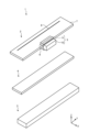
- FIG. 1 is a diagram schematically showing the configuration of a thermal head 1 according to an embodiment.
- an XYZ orthogonal coordinate system may be set, and the positional relationship of each part may be described with reference to this XYZ orthogonal coordinate system.
- a predetermined direction in the horizontal plane is the X-axis direction
- a direction perpendicular to the X-axis direction in the horizontal plane is the Y-axis direction
- a direction perpendicular to the X-axis direction and the Y-axis direction is the Z-axis direction.
- An XY plane containing the X and Y axes is parallel to the horizontal plane.
- the surface where the substrate 7 of the thermal head 1 is fitted with the connector 5 may be parallel to the horizontal plane.
- the Z-axis direction perpendicular to the XY plane is the vertical direction.
- the direction perpendicular to the surface where the substrate 7 of the thermal head 1 is fitted with the connector 5 may be parallel to the Z-axis.
- the thermal head 1 includes a head substrate 2, a radiator plate 3, an adhesive member 4, a connector 5, and a sealing member 6.
- the head base body 2 is formed, for example, in a substantially rectangular parallelepiped shape, and placed on the radiator plate 3 via the adhesive member 4 .
- Each member constituting the thermal head 1 is provided on the substrate 7 of the head substrate 2 .
- the head substrate 2 applies a voltage in accordance with an electric signal supplied from the outside through the connector 5 to generate heat in the heating portion 8 and print on the recording medium P (see FIG. 12).
- a voltage in accordance with an electric signal supplied from the outside through the connector 5 to generate heat in the heating portion 8 and print on the recording medium P (see FIG. 12).
- the connector 5 is joined to the head substrate 2 by a sealing member 6 and electrically connects the head substrate 2 to the outside.
- the adhesive member 4 bonds the head base 2 and the heat sink 3 together.
- the radiator plate 3 is formed, for example, in a substantially rectangular parallelepiped shape, and provided to radiate heat from the head base body 2 .
- the radiator plate 3 is made of, for example, a metal material such as copper, iron, or aluminum, and has a function of dissipating the heat generated in the heat generating portion 8 of the head base 2 that does not contribute to printing.
- FIG. 2 is a plan view showing a schematic configuration of the thermal head 1 shown in FIG. 1.
- FIG. 3 is a cross-sectional view taken along line AA shown in FIG. 2.
- the thermal head 1 includes a substrate 7, a heat storage layer 21, a resistance layer 22, a common electrode 23, an individual electrode 24, a first connection electrode 25, a ground electrode 26, a connection terminal 27, a second A connection electrode 28 , a drive IC 30 , a hard coat 31 , a protective layer 32 , a coating layer 33 and a bonding member 34 are further provided.
- the substrate 7 has a rectangular shape in plan view, and has a first long side 7a, a second long side 7b, a first short side 7c, a second short side 7d, a side surface 7e, a first surface 7f and a second surface 7g.
- the substrate 7 is made of, for example, an electrically insulating material such as alumina ceramics or a semiconductor material such as single crystal silicon.
- a connector 5 is provided on the side surface 7 e of the substrate 7 .
- the connector 5 is fixed to the side surface 7 e by connector pins 9 , joining members 34 and sealing members 6 .
- the joining member 34 has electrical conductivity and is arranged between the connection terminal 27 and the connector pin 9 . Examples of the joining member 34 include solder or an anisotropic conductive paste.
- a pad portion (not shown) that is a metal plating layer of Ni, Au, or Pd is provided between the joint member 34 and the connection terminal 27 . Note that the joining member 34 may not necessarily be provided.
- the connector 5 has a plurality of connector pins 9 and a housing 10 that accommodates the plurality of connector pins 9 .
- the plurality of connector pins 9 have first ends exposed outside the housing 10 and second ends housed inside the housing 10 .
- a plurality of connector pins 9 are electrically connected to connection terminals 27 of the head substrate 2 and electrically connected to various electrodes of the head substrate 2 .
- the sealing member 6 is provided so that the connection terminals 27 and the connector pins 9 are not exposed to the outside.
- the sealing member 6 can be made of, for example, an epoxy thermosetting resin, an ultraviolet curable resin, or a visible light curable resin.
- the heat storage layer 21 is located on the first surface 7 f of the substrate 7 .
- the heat storage layer 21 has a base portion 21a and a raised portion 21b.
- Base portion 21 a is located over the entire first surface 7 f of substrate 7 .
- the protruding portion 21b protrudes in the thickness direction of the substrate 7 from the base portion 21a. In other words, the raised portion 21b protrudes away from the first surface 7f of the substrate 7 .
- the raised portion 21b is positioned adjacent to the first long side 7a of the substrate 7 and extends along the main scanning direction.
- the raised portion 21b has a substantially semielliptical cross section. Therefore, the protective layer 32 located on the heat-generating portion 8 is in good contact with the recording medium P (see FIG. 12) to be printed.
- the height of the heat storage layer 21 from the first surface 7f of the substrate 7, including the underlying portion 21a and the raised portion 21b, can be 15 to 90 ⁇ m.
- the heat storage layer 21 is made of a material with low thermal conductivity, such as glass, and has the function of temporarily storing part of the heat generated by the heat generating section 8 . Therefore, the heat storage layer 21 can shorten the time required to raise the temperature of the heat generating portion 8 . As a result, the heat storage layer 21 functions to enhance the thermal response characteristics of the thermal head 1 .
- the heat storage layer 21 is formed by, for example, applying a predetermined glass paste obtained by mixing glass powder with an appropriate organic solvent to the upper surface of the substrate 7 by screen printing or the like, and firing the paste.
- the heat storage layer 21 is not limited to a glaze layer made of a glass material.
- the heat storage layer 21 is made of a dielectric material such as silicon oxide, and may be formed by various vapor phase synthesis methods (eg, PVD (Physical Vapor Deposition) or CVD (Chemical Vapor Deposition)).
- a plurality of heat generating parts 8 are arranged on the heat storage layer 21 along the longitudinal direction of the substrate 7 . Further, the plurality of heat generating portions 8 are arranged at predetermined intervals between a first short side 7c and a second short side 7d extending along the width direction of the sides of the first surface 7f of the substrate 7. be done.
- the common electrode 23 has main wiring portions 23a and 23d, a sub-wiring portion 23b, and a lead portion 23c.
- the common electrode 23 electrically connects the multiple heat generating portions 8 and the connector 5 .
- the main wiring portion 23 a extends along the first long side 7 a of the substrate 7 .
- Sub-wiring portion 23b extends along first short side 7c and second short side 7d of substrate 7, respectively.
- the individual electrode 24 electrically connects between the heating portion 8 and the drive IC 30 .
- the plurality of heat generating portions 8 are divided into a plurality of groups.
- the individual electrodes 24 electrically connect the plurality of heat generating portions 8 forming each group and the drive ICs 30 corresponding to each group. Note that the drive IC 30 will be described later.
- the first connection electrode 25 electrically connects between the drive IC 30 and the connector 5 .
- a plurality of first connection electrodes 25 are connected to each of the driving ICs 30, and each of these first connection electrodes 25 is composed of one or more wirings having different functions.
- Such a pad portion is made of, for example, a metal material such as Au.
- the pad portion may be made of Ni or Pd instead of Au.
- connection terminal 27 is provided on the second long side 7 b side of the substrate 7 and connects the common electrode 23 , the individual electrode 24 , the first connection electrode 25 and the ground electrode 26 to the connector 5 .
- the connection terminals 27 are provided so as to correspond to the connector pins 9, and when connecting the connector 5, the connector pins 9 and the connection terminals 27 are connected so as to be electrically independent from each other.
- a protective resin layer (not shown) is provided on the upper surface of the connection terminal 27 (the contact surface with the connector pin 9).
- the second connection electrodes 28 electrically connect adjacent drive ICs 30 to each other.
- the second connection electrodes 28 are provided so as to correspond to the first connection electrodes 25, respectively, and transmit various signals to the adjacent drive ICs 30. As shown in FIG.
- the resistance layer 22 and various electrodes can be formed, for example, as follows.
- the materials forming each are sequentially laminated on heat storage layer 21 by a thin film forming technique such as a sputtering method.
- the resistive layer 22 and various electrodes are formed by processing this laminate into a predetermined pattern using conventionally known photoetching or the like. In this manner, various electrodes are electrically connected to the heat generating portion 8 . Its thickness can be, for example, 0.1 to 1 ⁇ m.
- the drive IC 30 is arranged on the first surface 7f side of the substrate 7, for example. Further, the plurality of drive ICs 30 are arranged along the direction in which the heat generating portions 8 are arranged so as to correspond to the groups of the heat generating portions 8 assigned to the respective drive ICs 30 .
- the driving IC 30 is connected to the end of the individual electrode 24 on the side of the driving IC 30 and the end of the first connection electrode 25 on the side of the driving IC 30, and individually activates the respective heat generating portions 8 according to an electric signal supplied from the outside. Electric power for generating heat is supplied to the heating unit 8 .
- the driving IC 30 for example, a switching member having a plurality of switching elements inside can be used.
- the protective layer 32 is a member disposed on the heat storage layer 21 formed on the upper surface 7h1 of the substrate 7 and covering the heat generating section 8, the common electrode 23 and the individual electrodes 24. More specifically, the protective layer 32 is provided so as to partially cover the individual electrodes 24 from the edge of the substrate 7, that is, the first long side 7a, the first short side 7c and the second short side 7d of the substrate 7. As shown in FIG.
- the protective layer 32 protects the heating portion 8, the common electrode 23, and the individual electrodes 24 from corrosion due to the adhesion of moisture contained in the atmosphere, or from abrasion due to contact with the recording medium P on which printing is performed. .
- Protective layer 32 can be formed using, for example, SiN, SiO 2 , SiON, SiC, or diamond-like carbon.
- the protective layer 32 may be composed of a single layer or multiple layers.
- the covering layer 33 is provided on the substrate 7 so as to partially cover the common electrode 23 , the individual electrodes 24 , the first connection electrodes 25 and the protective layer 32 .
- the coating layer 33 protects the coated area from oxidation due to contact with the atmosphere or corrosion due to adhesion of moisture contained in the atmosphere.
- the coating layer 33 is in close contact with the protective layer 32 to cover the end portion of the protective layer 32, thereby preventing the problem that the protective layer 32 is peeled off from the object to be protected, such as the heating portion 8 or various electrodes. Reduce occurrence.
- the drive IC 30 is sealed with the hard coat 31 while being connected to the individual electrodes 24 and the first connection electrodes 25 . This protects the drive IC 30 or the connection between the drive IC 30 and these electrodes.
- Hard coat 31 is made of resin such as epoxy resin or silicone resin.
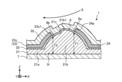
- FIG. 4 is a cross-sectional view showing an example of a main part of the thermal head 1 according to the embodiment.
- the base portion 21a located downstream of the raised portion 21b may not be present. In the absence of the base portion 21a, the temperature of the second portion 8b tends to be lower, so that the designated portion of the recording medium P can be printed with better quality.
- a stepped portion 21c is provided in the vicinity of the top portion 21b1 of the heat storage layer 21 .
- the stepped portion 21c is formed by a rapid decrease in thickness of the heat storage layer 21 in the vicinity of the top portion 21b1 as the transport direction S progresses.
- the stepped portion 21c is not provided so as to rise vertically with respect to the first surface 7f of the substrate 7, but the thickness of the heat storage layer 21 changes along the curved surface at the stepped portion 21c.
- Such a step portion 21c may be provided.
- the protective layer 32 is provided with a sharp corner, so that the recording medium P is torn. This problem can be reduced.
- the temperature of the recording medium P (see FIG. 12) can be increased more quickly in the first portion 8a, so that the speed of the thermal head 1 can be further increased.
- the third embodiment it is possible to achieve both high-speed operation of the thermal head 1 and good print quality, as in the embodiment.
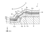
- the heat storage layer 21 and the heat generating portion 8 are located over a plurality of surfaces of the substrate 7 (here, the upper surface 7h1 and the side surface 7h2).
- the angle formed between the upper surface 7h1 facing the first portion 8a and the printing surface of the recording medium P is smaller than the angle formed between the side surface 7h2 facing the second portion 8b and the printing surface of the recording medium P.
- the recording medium P (see FIG. 12) and the upper surface 7h1 are nearly parallel and face each other at a relatively small angle, so the pressing pressure on the recording medium P can be increased.
- the heat transfer efficiency from the heat generating portion 8 to the recording medium P can be improved on the upstream side, and the heat from the heat generating portion 8 is excessively transferred to the recording medium P on the downstream side. can be reduced.
- the thickness of the heat storage layer 21 is T3>T1>T2.
- the protective layer 32 has a convex shape between the first portion 8a and the second portion 8b of the heat generating portion 8, so that the recording medium P (see FIG. 12) is placed over the heat generating portion 8 of the thermal head 1. It can facilitate contact with the protective layer 32 located.
- the thermal printer 100 includes the thermal head 1 described above, a transport mechanism 40, a platen roller 50, a power supply device 60, and a control device .
- the power supply device 60 has a function of supplying a current for heating the heat generating portion 8 of the thermal head 1 and a current for operating the drive IC 30 as described above.
- the control device 70 has a function of supplying a control signal for controlling the operation of the driving IC 30 to the driving IC 30 in order to selectively heat the heat generating portion 8 of the thermal head 1 as described above.
- the thermal printer 100 presses the recording medium P onto the heat generating portion 8 of the thermal head 1 with the platen roller 50 and conveys the recording medium P onto the heat generating portion 8 with the conveying mechanism 40 .
- a predetermined image is printed on the recording medium P. As shown in FIG.
- the recording medium P is an image-receiving paper or the like
- printing is performed on the recording medium P by thermally transferring ink from an ink film (not shown) conveyed together with the recording medium P onto the recording medium P.
- the thermal head 1 includes a substrate 7 , a heat storage layer 21 positioned on the substrate 7 , and a heat generating portion 8 positioned on the heat storage layer 21 . Further, when the transport direction S of the recording medium P is defined as a first direction and the direction opposite to the first direction is defined as a second direction, in the heat storage layer 21, the end portion (first portion) of the heat generating portion 8 on the second direction side The thickness T1 of the portion located under 8a) is thicker than the thickness T2 of the portion located under the end portion (second portion 8b) of the heat generating portion 8 on the first direction side. As a result, it is possible to achieve both high-speed operation of the thermal head 1 and good print quality.
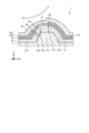
- the heat storage layer 21 has a first heat storage layer 21A and a second heat storage layer 21B.
- the first heat storage layer 21A is located between the end portion (first portion 8a) of the heat generating portion 8 on the second direction side and the substrate 7, and between the end portion (second portion 8b) of the heat generating portion 8 on the first direction side. It is positioned between the substrate 7 and the substrate 7 .
- the second heat storage layer 21B has a smaller thermal conductivity than the first heat storage layer 21A, and is positioned between the substrate 7 and the end portion (first portion 8a) of the heat generating portion 8 on the second direction side. As a result, the speed of the thermal head 1 can be further increased.
- the second heat storage layer 21B is positioned between the first heat storage layer 21A and the heat generating portion 8. As a result, the speed of the thermal head 1 can be further increased.
- the heat storage layer 21 and the heat generating portion 8 are positioned over a plurality of surfaces (the upper surface 7h1 and the side surface 7h2) of the substrate 7. Further, the angle formed by the surface (upper surface 7h1) of the substrate 7 facing the end portion (first portion 8a) of the heat generating portion 8 on the second direction side and the printing surface of the recording medium P is is smaller than the angle formed by the surface (side surface 7h2) of the substrate 7 facing the end (second portion 8b) of the substrate 7 and the printing surface of the recording medium P. As a result, it is possible to achieve both high-speed operation of the thermal head 1 and good print quality at a high level.
- the thickness T3 of the portion of the heat storage layer 21 located on the ridge 7h3 between the surfaces of the substrate 7 is equal to It is thicker than the thickness T1 of the portion located under (the first portion 8a) and the thickness T2 of the portion located under the end (second portion 8b) of the exothermic portion 8 on the first direction side.
- the tolerance of the head mounting angle in the thermal printer 100 can be increased.
- the heat storage layer 21 includes a portion located under the end portion (first portion 8a) of the heat generating portion 8 on the second direction side and It has a stepped portion 21c between the end portion (first portion 8a) and the lower portion. Moreover, the thickness of the heat storage layer 21 changes along the curved surface at the stepped portion 21c. As a result, when the recording medium P is pressed against the heat generating portion 8 by the platen roller 50 , it is possible to reduce the problem that the recording medium P is torn due to the provision of the angled portions in the protective layer 32 .
- the thermal printer 100 includes the above-described thermal head 1, a transport mechanism 40 that transports the recording medium P onto the heat generating section 8, and a platen roller 50 that presses the recording medium P onto the heat generating section 8. And prepare. As a result, it is possible to realize the thermal printer 100 that achieves both high speed and good print quality.
- the heat generating portion 8 may be positioned on the side surface of the substrate 7 on the side of the first long side 7a, or the heat generating portion 8 may extend along the first long side 7a of the substrate 7 from the top surface to the side surface. It may be formed on a slope that is separately formed over .
- the protrusion 7h has a trapezoidal shape in cross-section
- the present disclosure is not limited to such an example, and may have, for example, a polygonal shape in cross-section. .
- thermal head 7 substrate 7h protrusion 7h1 upper surface 7h2 side surface 7h3 edge 8 heat generating portion 8a first portion 8b second portion 21 heat storage layer 21A first heat storage layer 21B second heat storage layer 21c stepped portion 22 resistance layer 23 common electrode 24 individual electrode 40 transport mechanism 50 platen roller 100 thermal printer P recording medium S transport direction T1 to T3 thickness
Landscapes
- Physics & Mathematics (AREA)
- Geometry (AREA)
- Electronic Switches (AREA)
Priority Applications (3)
| Application Number | Priority Date | Filing Date | Title |
|---|---|---|---|
| JP2023569238A JPWO2023120093A1 (https=) | 2021-12-24 | 2022-12-01 | |
| US18/722,591 US20250058567A1 (en) | 2021-12-24 | 2022-12-01 | Thermal head and thermal printer |
| CN202280080796.9A CN118369214A (zh) | 2021-12-24 | 2022-12-01 | 热敏头以及热敏打印机 |
Applications Claiming Priority (2)
| Application Number | Priority Date | Filing Date | Title |
|---|---|---|---|
| JP2021-211727 | 2021-12-24 | ||
| JP2021211727 | 2021-12-24 |
Publications (1)
| Publication Number | Publication Date |
|---|---|
| WO2023120093A1 true WO2023120093A1 (ja) | 2023-06-29 |
Family
ID=86902090
Family Applications (1)
| Application Number | Title | Priority Date | Filing Date |
|---|---|---|---|
| PCT/JP2022/044409 Ceased WO2023120093A1 (ja) | 2021-12-24 | 2022-12-01 | サーマルヘッドおよびサーマルプリンタ |
Country Status (4)
| Country | Link |
|---|---|
| US (1) | US20250058567A1 (https=) |
| JP (1) | JPWO2023120093A1 (https=) |
| CN (1) | CN118369214A (https=) |
| WO (1) | WO2023120093A1 (https=) |
Citations (5)
| Publication number | Priority date | Publication date | Assignee | Title |
|---|---|---|---|---|
| JPS6119374A (ja) * | 1984-07-04 | 1986-01-28 | Canon Inc | サ−マルヘツド |
| JPH09109428A (ja) * | 1995-10-17 | 1997-04-28 | Tec Corp | サーマルヘッド及びその製造方法 |
| JP2000135805A (ja) * | 1998-10-30 | 2000-05-16 | Kyocera Corp | 感熱記録装置 |
| JP2009107201A (ja) * | 2007-10-30 | 2009-05-21 | Kyocera Corp | サーマルヘッド、サーマルヘッドの製造方法、およびサーマルプリンタ |
| CN109693451A (zh) * | 2019-01-28 | 2019-04-30 | 山东华菱电子股份有限公司 | 一种热敏打印头用发热基板及其制造方法 |
Family Cites Families (4)
| Publication number | Priority date | Publication date | Assignee | Title |
|---|---|---|---|---|
| JPH06340101A (ja) * | 1993-05-31 | 1994-12-13 | Kyocera Corp | サーマルヘッド |
| JP7141520B2 (ja) * | 2019-03-26 | 2022-09-22 | 京セラ株式会社 | サーマルヘッドおよびサーマルプリンタ |
| JP7411461B2 (ja) * | 2020-03-16 | 2024-01-11 | 京セラ株式会社 | サーマルヘッドおよびサーマルプリンタ |
| JP7481158B2 (ja) * | 2020-04-27 | 2024-05-10 | ローム株式会社 | サーマルプリントヘッドおよびサーマルプリンタ |
-
2022
- 2022-12-01 JP JP2023569238A patent/JPWO2023120093A1/ja active Pending
- 2022-12-01 WO PCT/JP2022/044409 patent/WO2023120093A1/ja not_active Ceased
- 2022-12-01 CN CN202280080796.9A patent/CN118369214A/zh active Pending
- 2022-12-01 US US18/722,591 patent/US20250058567A1/en active Pending
Patent Citations (5)
| Publication number | Priority date | Publication date | Assignee | Title |
|---|---|---|---|---|
| JPS6119374A (ja) * | 1984-07-04 | 1986-01-28 | Canon Inc | サ−マルヘツド |
| JPH09109428A (ja) * | 1995-10-17 | 1997-04-28 | Tec Corp | サーマルヘッド及びその製造方法 |
| JP2000135805A (ja) * | 1998-10-30 | 2000-05-16 | Kyocera Corp | 感熱記録装置 |
| JP2009107201A (ja) * | 2007-10-30 | 2009-05-21 | Kyocera Corp | サーマルヘッド、サーマルヘッドの製造方法、およびサーマルプリンタ |
| CN109693451A (zh) * | 2019-01-28 | 2019-04-30 | 山东华菱电子股份有限公司 | 一种热敏打印头用发热基板及其制造方法 |
Also Published As
| Publication number | Publication date |
|---|---|
| JPWO2023120093A1 (https=) | 2023-06-29 |
| US20250058567A1 (en) | 2025-02-20 |
| CN118369214A (zh) | 2024-07-19 |
Similar Documents
| Publication | Publication Date | Title |
|---|---|---|
| JP5836825B2 (ja) | サーマルヘッドおよびこれを備えるサーマルプリンタ | |
| JP2016164005A (ja) | サーマルヘッドおよびこれを備えるサーマルプリンタ | |
| JP6196417B1 (ja) | サーマルヘッドおよびサーマルプリンタ | |
| JP6059412B1 (ja) | サーマルヘッドおよびサーマルプリンタ | |
| JP7309040B2 (ja) | サーマルヘッドおよびサーマルプリンタ | |
| JP7336588B2 (ja) | サーマルヘッドおよびサーマルプリンタ | |
| CN107848311A (zh) | 热敏头及热敏打印机 | |
| JP6419006B2 (ja) | サーマルヘッドおよびサーマルプリンタ | |
| JP6130510B2 (ja) | サーマルヘッドおよびこれを備えるサーマルプリンタ | |
| CN108883641B (zh) | 热敏头及热敏打印机 | |
| JPWO2016104479A1 (ja) | サーマルヘッドおよびサーマルプリンタ | |
| WO2023120093A1 (ja) | サーマルヘッドおよびサーマルプリンタ | |
| JP7444972B2 (ja) | サーマルヘッドおよびサーマルプリンタ | |
| JP7411461B2 (ja) | サーマルヘッドおよびサーマルプリンタ | |
| JP7267905B2 (ja) | サーマルヘッド及びサーマルプリンタ | |
| WO2020196078A1 (ja) | サーマルヘッドおよびサーマルプリンタ | |
| US11945233B2 (en) | Thermal head and thermal printer | |
| JP6525819B2 (ja) | サーマルヘッドおよびサーマルプリンタ | |
| JP6426541B2 (ja) | サーマルヘッドおよびサーマルプリンタ | |
| JP2018138365A (ja) | サーマルヘッドおよびサーマルプリンタ | |
| JP7036692B2 (ja) | サーマルヘッドおよびサーマルプリンタ | |
| WO2025244111A1 (ja) | サーマルヘッドおよびサーマルプリンタ | |
| WO2026028989A1 (ja) | サーマルヘッドおよびサーマルプリンタ | |
| JP6525822B2 (ja) | サーマルヘッドおよびサーマルプリンタ | |
| JP6670654B2 (ja) | サーマルヘッドおよびサーマルプリンタ |
Legal Events
| Date | Code | Title | Description |
|---|---|---|---|
| 121 | Ep: the epo has been informed by wipo that ep was designated in this application |
Ref document number: 22910810 Country of ref document: EP Kind code of ref document: A1 |
|
| WWE | Wipo information: entry into national phase |
Ref document number: 202280080796.9 Country of ref document: CN Ref document number: 2023569238 Country of ref document: JP |
|
| WWE | Wipo information: entry into national phase |
Ref document number: 18722591 Country of ref document: US |
|
| NENP | Non-entry into the national phase |
Ref country code: DE |
|
| 122 | Ep: pct application non-entry in european phase |
Ref document number: 22910810 Country of ref document: EP Kind code of ref document: A1 |