WO2023120003A1 - ディスクブレーキ - Google Patents
ディスクブレーキ Download PDFInfo
- Publication number
- WO2023120003A1 WO2023120003A1 PCT/JP2022/043128 JP2022043128W WO2023120003A1 WO 2023120003 A1 WO2023120003 A1 WO 2023120003A1 JP 2022043128 W JP2022043128 W JP 2022043128W WO 2023120003 A1 WO2023120003 A1 WO 2023120003A1
- Authority
- WO
- WIPO (PCT)
- Prior art keywords
- substrate portion
- disc brake
- motor
- electric motor
- substrate
- Prior art date
- Legal status (The legal status is an assumption and is not a legal conclusion. Google has not performed a legal analysis and makes no representation as to the accuracy of the status listed.)
- Ceased
Links
Images





Classifications
-
- B—PERFORMING OPERATIONS; TRANSPORTING
- B60—VEHICLES IN GENERAL
- B60T—VEHICLE BRAKE CONTROL SYSTEMS OR PARTS THEREOF; BRAKE CONTROL SYSTEMS OR PARTS THEREOF, IN GENERAL; ARRANGEMENT OF BRAKING ELEMENTS ON VEHICLES IN GENERAL; PORTABLE DEVICES FOR PREVENTING UNWANTED MOVEMENT OF VEHICLES; VEHICLE MODIFICATIONS TO FACILITATE COOLING OF BRAKES
- B60T13/00—Transmitting braking action from initiating means to ultimate brake actuator with power assistance or drive; Brake systems incorporating such transmitting means, e.g. air-pressure brake systems
- B60T13/74—Transmitting braking action from initiating means to ultimate brake actuator with power assistance or drive; Brake systems incorporating such transmitting means, e.g. air-pressure brake systems with electrical assistance or drive
-
- B—PERFORMING OPERATIONS; TRANSPORTING
- B60—VEHICLES IN GENERAL
- B60T—VEHICLE BRAKE CONTROL SYSTEMS OR PARTS THEREOF; BRAKE CONTROL SYSTEMS OR PARTS THEREOF, IN GENERAL; ARRANGEMENT OF BRAKING ELEMENTS ON VEHICLES IN GENERAL; PORTABLE DEVICES FOR PREVENTING UNWANTED MOVEMENT OF VEHICLES; VEHICLE MODIFICATIONS TO FACILITATE COOLING OF BRAKES
- B60T13/00—Transmitting braking action from initiating means to ultimate brake actuator with power assistance or drive; Brake systems incorporating such transmitting means, e.g. air-pressure brake systems
- B60T13/74—Transmitting braking action from initiating means to ultimate brake actuator with power assistance or drive; Brake systems incorporating such transmitting means, e.g. air-pressure brake systems with electrical assistance or drive
- B60T13/741—Transmitting braking action from initiating means to ultimate brake actuator with power assistance or drive; Brake systems incorporating such transmitting means, e.g. air-pressure brake systems with electrical assistance or drive acting on an ultimate actuator
-
- F—MECHANICAL ENGINEERING; LIGHTING; HEATING; WEAPONS; BLASTING
- F16—ENGINEERING ELEMENTS AND UNITS; GENERAL MEASURES FOR PRODUCING AND MAINTAINING EFFECTIVE FUNCTIONING OF MACHINES OR INSTALLATIONS; THERMAL INSULATION IN GENERAL
- F16D—COUPLINGS FOR TRANSMITTING ROTATION; CLUTCHES; BRAKES
- F16D55/00—Brakes with substantially-radial braking surfaces pressed together in axial direction, e.g. disc brakes
- F16D55/02—Brakes with substantially-radial braking surfaces pressed together in axial direction, e.g. disc brakes with axially-movable discs or pads pressed against axially-located rotating members
- F16D55/22—Brakes with substantially-radial braking surfaces pressed together in axial direction, e.g. disc brakes with axially-movable discs or pads pressed against axially-located rotating members by clamping an axially-located rotating disc between movable braking members, e.g. movable brake discs or brake pads
- F16D55/224—Brakes with substantially-radial braking surfaces pressed together in axial direction, e.g. disc brakes with axially-movable discs or pads pressed against axially-located rotating members by clamping an axially-located rotating disc between movable braking members, e.g. movable brake discs or brake pads with a common actuating member for the braking members
- F16D55/225—Brakes with substantially-radial braking surfaces pressed together in axial direction, e.g. disc brakes with axially-movable discs or pads pressed against axially-located rotating members by clamping an axially-located rotating disc between movable braking members, e.g. movable brake discs or brake pads with a common actuating member for the braking members the braking members being brake pads
- F16D55/226—Brakes with substantially-radial braking surfaces pressed together in axial direction, e.g. disc brakes with axially-movable discs or pads pressed against axially-located rotating members by clamping an axially-located rotating disc between movable braking members, e.g. movable brake discs or brake pads with a common actuating member for the braking members the braking members being brake pads in which the common actuating member is moved axially, e.g. floating caliper disc brakes
-
- F—MECHANICAL ENGINEERING; LIGHTING; HEATING; WEAPONS; BLASTING
- F16—ENGINEERING ELEMENTS AND UNITS; GENERAL MEASURES FOR PRODUCING AND MAINTAINING EFFECTIVE FUNCTIONING OF MACHINES OR INSTALLATIONS; THERMAL INSULATION IN GENERAL
- F16D—COUPLINGS FOR TRANSMITTING ROTATION; CLUTCHES; BRAKES
- F16D65/00—Parts or details
- F16D65/14—Actuating mechanisms for brakes; Means for initiating operation at a predetermined position
- F16D65/16—Actuating mechanisms for brakes; Means for initiating operation at a predetermined position arranged in or on the brake
- F16D65/18—Actuating mechanisms for brakes; Means for initiating operation at a predetermined position arranged in or on the brake adapted for drawing members together, e.g. for disc brakes
-
- F—MECHANICAL ENGINEERING; LIGHTING; HEATING; WEAPONS; BLASTING
- F16—ENGINEERING ELEMENTS AND UNITS; GENERAL MEASURES FOR PRODUCING AND MAINTAINING EFFECTIVE FUNCTIONING OF MACHINES OR INSTALLATIONS; THERMAL INSULATION IN GENERAL
- F16D—COUPLINGS FOR TRANSMITTING ROTATION; CLUTCHES; BRAKES
- F16D65/00—Parts or details
- F16D65/14—Actuating mechanisms for brakes; Means for initiating operation at a predetermined position
- F16D65/16—Actuating mechanisms for brakes; Means for initiating operation at a predetermined position arranged in or on the brake
- F16D65/18—Actuating mechanisms for brakes; Means for initiating operation at a predetermined position arranged in or on the brake adapted for drawing members together, e.g. for disc brakes
- F16D65/183—Actuating mechanisms for brakes; Means for initiating operation at a predetermined position arranged in or on the brake adapted for drawing members together, e.g. for disc brakes with force-transmitting members arranged side by side acting on a spot type force-applying member
-
- H—ELECTRICITY
- H02—GENERATION; CONVERSION OR DISTRIBUTION OF ELECTRIC POWER
- H02K—DYNAMO-ELECTRIC MACHINES
- H02K11/00—Structural association of dynamo-electric machines with electric components or with devices for shielding, monitoring or protection
- H02K11/30—Structural association with control circuits or drive circuits
- H02K11/33—Drive circuits, e.g. power electronics
-
- H—ELECTRICITY
- H02—GENERATION; CONVERSION OR DISTRIBUTION OF ELECTRIC POWER
- H02K—DYNAMO-ELECTRIC MACHINES
- H02K7/00—Arrangements for handling mechanical energy structurally associated with dynamo-electric machines, e.g. structural association with mechanical driving motors or auxiliary dynamo-electric machines
- H02K7/06—Means for converting reciprocating motion into rotary motion or vice versa
-
- H—ELECTRICITY
- H02—GENERATION; CONVERSION OR DISTRIBUTION OF ELECTRIC POWER
- H02K—DYNAMO-ELECTRIC MACHINES
- H02K7/00—Arrangements for handling mechanical energy structurally associated with dynamo-electric machines, e.g. structural association with mechanical driving motors or auxiliary dynamo-electric machines
- H02K7/10—Structural association with clutches, brakes, gears, pulleys or mechanical starters
- H02K7/116—Structural association with clutches, brakes, gears, pulleys or mechanical starters with gears
-
- B—PERFORMING OPERATIONS; TRANSPORTING
- B60—VEHICLES IN GENERAL
- B60T—VEHICLE BRAKE CONTROL SYSTEMS OR PARTS THEREOF; BRAKE CONTROL SYSTEMS OR PARTS THEREOF, IN GENERAL; ARRANGEMENT OF BRAKING ELEMENTS ON VEHICLES IN GENERAL; PORTABLE DEVICES FOR PREVENTING UNWANTED MOVEMENT OF VEHICLES; VEHICLE MODIFICATIONS TO FACILITATE COOLING OF BRAKES
- B60T13/00—Transmitting braking action from initiating means to ultimate brake actuator with power assistance or drive; Brake systems incorporating such transmitting means, e.g. air-pressure brake systems
- B60T13/74—Transmitting braking action from initiating means to ultimate brake actuator with power assistance or drive; Brake systems incorporating such transmitting means, e.g. air-pressure brake systems with electrical assistance or drive
- B60T13/746—Transmitting braking action from initiating means to ultimate brake actuator with power assistance or drive; Brake systems incorporating such transmitting means, e.g. air-pressure brake systems with electrical assistance or drive and mechanical transmission of the braking action
-
- F—MECHANICAL ENGINEERING; LIGHTING; HEATING; WEAPONS; BLASTING
- F16—ENGINEERING ELEMENTS AND UNITS; GENERAL MEASURES FOR PRODUCING AND MAINTAINING EFFECTIVE FUNCTIONING OF MACHINES OR INSTALLATIONS; THERMAL INSULATION IN GENERAL
- F16D—COUPLINGS FOR TRANSMITTING ROTATION; CLUTCHES; BRAKES
- F16D2121/00—Type of actuator operation force
- F16D2121/18—Electric or magnetic
- F16D2121/24—Electric or magnetic using motors
-
- F—MECHANICAL ENGINEERING; LIGHTING; HEATING; WEAPONS; BLASTING
- F16—ENGINEERING ELEMENTS AND UNITS; GENERAL MEASURES FOR PRODUCING AND MAINTAINING EFFECTIVE FUNCTIONING OF MACHINES OR INSTALLATIONS; THERMAL INSULATION IN GENERAL
- F16D—COUPLINGS FOR TRANSMITTING ROTATION; CLUTCHES; BRAKES
- F16D2125/00—Components of actuators
- F16D2125/18—Mechanical mechanisms
- F16D2125/20—Mechanical mechanisms converting rotation to linear movement or vice versa
- F16D2125/34—Mechanical mechanisms converting rotation to linear movement or vice versa acting in the direction of the axis of rotation
- F16D2125/40—Screw-and-nut
-
- F—MECHANICAL ENGINEERING; LIGHTING; HEATING; WEAPONS; BLASTING
- F16—ENGINEERING ELEMENTS AND UNITS; GENERAL MEASURES FOR PRODUCING AND MAINTAINING EFFECTIVE FUNCTIONING OF MACHINES OR INSTALLATIONS; THERMAL INSULATION IN GENERAL
- F16D—COUPLINGS FOR TRANSMITTING ROTATION; CLUTCHES; BRAKES
- F16D2125/00—Components of actuators
- F16D2125/18—Mechanical mechanisms
- F16D2125/44—Mechanical mechanisms transmitting rotation
- F16D2125/46—Rotating members in mutual engagement
- F16D2125/48—Rotating members in mutual engagement with parallel stationary axes, e.g. spur gears
-
- H—ELECTRICITY
- H02—GENERATION; CONVERSION OR DISTRIBUTION OF ELECTRIC POWER
- H02K—DYNAMO-ELECTRIC MACHINES
- H02K2211/00—Specific aspects not provided for in the other groups of this subclass relating to measuring or protective devices or electric components
- H02K2211/03—Machines characterised by circuit boards, e.g. pcb
Definitions
- the present invention relates to disc brakes used for braking vehicles.
- a control circuit board and a drive circuit board are arranged so as to be stacked along the axial direction of the output shaft of the motor, as shown in Patent Document 1.
- the output shaft of the motor is provided on the side of the control circuit board and the drive circuit board.
- these control circuit board and drive circuit board are provided on the output shaft side of the motor, these control circuit board and drive circuit board, more specifically, on these control circuit board and drive circuit board.
- One of the objects of the present invention is to provide a disk brake that suppresses the transmission of vibration and heat transfer from the motor and disk rotor to the components mounted on the substrate, thereby improving reliability.
- a disc brake according to the present invention includes a motor and a rotary-to-linear motion converter that converts rotary motion transmitted from an output shaft of the motor into linear motion to press a friction pad. a mechanism, a first substrate portion connected to the motor and arranged on the opposite side of the motor output shaft in the axial direction, and a first substrate portion connected to the first substrate portion and facing the first substrate portion. and a second substrate portion that is spaced apart from the first substrate portion by a predetermined distance.
- a disk brake according to the present invention includes a motor, a rotation-to-linear motion conversion mechanism that converts rotary motion transmitted from an output shaft of the motor into linear motion and presses a friction pad, and a mechanism connected to the motor. a first substrate portion disposed radially outwardly of the motor; and a first substrate portion connected to the first substrate portion, opposed to the first substrate portion, and disposed at a predetermined distance from the first substrate portion. and a second substrate portion.
- the disc brake according to one embodiment of the present invention, it is possible to suppress the transmission of vibration and heat from the motor and the disc rotor to the components mounted on the substrate, and as a result, it is possible to improve the reliability. .
- FIG. 1 is a perspective view of a disc brake according to an embodiment of the invention
- FIG. FIG. 2 is a perspective view of the disc brake according to the embodiment of the present invention, viewed from a direction different from that in FIG. 1
- 1 is a plan view including a partial cross section of a disc brake according to an embodiment of the present invention
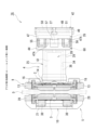
- FIG. 1 is a side view including a partial cross section of a disc brake according to an embodiment of the present invention
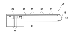
- FIG. 2 is a side view of a control unit employed in the disc brake according to the embodiment of the invention; The side view including the partial cross section of the disc brake which concerns on other embodiment.
- the disc brake 1A is an electric brake device that generates a braking force by driving an electric motor 26 (see FIG. 3), and is employed as a braking device during normal running of the vehicle, during parking braking, and the like. be.
- the inner side of the vehicle is called the inner side
- the outer side of the vehicle is called the outer side.
- the inner side may be referred to as one end side
- the outer side may be referred to as the other end side.
- a disc brake 1A according to the present embodiment includes a pair of inner rotors arranged on both sides in the axial direction across a disc rotor D (see FIG. 3) attached to a rotating portion of a vehicle.
- a brake pad 2 (see FIG. 2), an outer brake pad 3 (see FIG. 1), and a caliper 4 are provided. 1 and 2, illustration of the disk rotor D is omitted.
- a disc brake 1A is configured as a caliper floating type.
- a pair of inner brake pads 2 and outer brake pads 3 and a caliper 4 are attached to a carrier 5 fixed to a non-rotating portion such as a knuckle (not shown) of a vehicle. supported so as to be movable to A pair of the inner brake pad 2 and the outer brake pad 3 correspond to friction pads.
- carrier 5 is integrally connected to a pair of pin connecting portions 8, 8 to which slide pins 38, 38, which will be described later, are respectively connected, and to the pair of pin connecting portions 8, 8. , and inner and outer side support portions 9 and 10 for independently supporting the inner and outer brake pads 2 and 3, respectively.
- the pair of pin connecting portions 8, 8 are arranged at intervals along the rotation direction of the disk rotor D. As shown in FIG.
- Each pin connecting portion 8 is integrally connected to an inner side arm portion 13 of an inner side support portion 9 to be described later and an outer side arm portion 20 of an outer side support portion 10 to be described later, and each pin sliding portion 31 to be described later. protruded on the side.
- the inner-side support portion 9 includes a pair of inner-side arm portions 13, 13 arranged at intervals along the rotation direction of the disk rotor D and extending in a direction perpendicular to the axial direction of the slide pin 38, which will be described later. and an inner beam portion 14 that connects the ends of the pair of inner side arm portions 13, 13 opposite to the pin connecting portion 8.
- the inner brake pad 2 is supported inside the pair of inner side arm portions 13 , 13 of the inner side support portion 9 so as to be movable along the axial direction of the disc rotor D.
- a pair of fixing portions 16, 16 for fixing the carrier 5 to a non-rotating portion of the vehicle are integrally connected to both ends of the inner beam portion 14 in the rotation direction of the disk rotor D.
- the outer side support portion 10 includes a pair of outer side arm portions 20, 20 arranged on the outer side with a space from the pair of inner side arm portions 13, 13 of the inner side support portion 9, and the pair of outer side arms. and an outer side beam portion 21 that connects the ends of the portions 20 , 20 opposite to the pin connecting portion 8 .
- the outer brake pad 3 is supported inside the pair of outer arm portions 20 , 20 of the outer support portion 10 so as to be movable along the axial direction of the disc rotor D. As shown in FIG.
- the carrier 5 is fixed to a non-rotating portion of the vehicle via a pair of fixing portions 16 , 16 of the inner side support portion 9 .
- the caliper 4 includes a caliper body 25, which is the main body of the caliper 4, an electric motor 26, and a speed reduction mechanism 60 and a rotation/linear motion conversion mechanism 61. and a braking mechanism 28 that transmits the driving force from the motor 26 to the piston 36 in the cylinder portion 29 of the caliper body 25 via the reduction mechanism 60 and the rotation/linear motion conversion mechanism 61 .
- the caliper main body 25 is arranged on the base end side facing the inner brake pad 2, and includes a cylindrical cylinder portion 29 that opens facing the inner brake pad 2, and a cylinder portion.
- a pair of claw portions 30, 30 extending from 29 to the outer side across the disc rotor D and arranged on the tip end side facing the outer brake pad 3 and the cylinder portion 29 are separated from each other in the direction of rotation of the disc rotor D.
- a pair of pin sliding portions 31, 31 protruding from the position where the is placed are integrally formed.
- detailed plan view shapes such as raised portions near the base portions of the pair of claw portions 30, 30 are omitted.
- the cylinder portion 29 is formed with a substantially circular cylinder bore 34 that opens from the other end face.
- a piston 36 is inserted into the cylinder bore 34 so as to be non-rotatable relative to the cylinder portion 29 and movable along the axial direction.
- the piston 36 has, for example, a cup shape consisting of a cylindrical portion and a bottom portion, and its axial direction coincides with the axial direction of the disk rotor D and the slide pin 38 .
- the driving force from the electric motor 26 is transmitted to the piston 36 in the cylinder portion 29 via the braking mechanism 28, and the piston 36 advances toward the disk rotor D.
- the bottom presses the inner brake pad 2 while it is moving.
- the brake is released, the driving force from the electric motor 26 is transmitted to the piston 36 via the braking mechanism 28, so that the piston 36 retreats from the disk rotor D.
- a cylinder portion 29 of the caliper body 25 is provided with a pair of pin sliding portions 31, 31 integrally protruding outward along the rotational direction of the disk rotor D. be done.
- Each pin sliding portion 31 extends along the axial direction of the disk rotor D.
- Each pin sliding portion 31 is formed in a bottomed cylindrical shape with the other end surface open.
- a pair of slide pins 38, 38 are inserted into the pair of pin sliding portions 31, 31 so as to be slidable along the axial direction.
- Each of the pin sliding portions 31 , 31 is arranged closer to one end than the pair of pin connecting portions 8 , 8 of the carrier 5 .
- the slide pin 38 extends along the axial direction of the disk rotor D.
- the slide pin 38 is formed in an elongated circular cross section.
- a pair of slide pins 38, 38 are slidably inserted in the respective pin sliding portions 31, 31 provided in the cylinder portion 29 from the other end side along the axial direction.
- a pair of slide pins 38 , 38 are respectively connected to corresponding pin connections 8 , 8 of the carrier 5 .
- Pin boots 39, 39 having expandable bellows are provided to cover the slide pins 38, 38, respectively.
- the caliper main body 25 (caliper 4) slides against the carrier 5 by sliding the pair of slide pins 38, 38 in the respective pin sliding portions 31, 31 provided in the cylinder portion 29. It can be slidably supported along the axial direction.
- a control unit (ECU) 42 for controlling the rotation of the electric motor 26 is electrically connected.
- the electric motor 26 is accommodated in a cylindrical motor gear housing 44 arranged on one end side from the bottom of the cylinder portion 29 .
- the electric motor 26 is arranged inside the motor gear housing 44 at one end thereof.
- a rotary shaft 27 of the electric motor 26 extends toward the other end, and its rotational drive is transmitted to a speed reduction mechanism 60, which will be described later.
- the rotary shaft 27 corresponds to the output shaft.
- the axial direction of the rotating shaft 27 of the electric motor 26 coincides with the axial direction of the disk rotor D. As shown in FIG.
- the rotating shaft 27 of the electric motor 26 and the cylinder bore 34 of the cylinder portion 29 are arranged substantially concentrically.
- the control unit 42 receives, for example, a detection signal from a detection sensor that responds to a request from the driver, a detection sensor that detects various situations requiring braking, and a wheel speed detection sensor that detects the wheel speed.
- a detection signal from a rotation angle detection means (not shown) for detecting the rotation angle of the rotation shaft 27 of the electric motor 26, and the thrust force (pressing force ), the rotation of the electric motor 26 (rotation direction, rotation speed, etc.) is controlled based on various detection signals such as a detection signal from a thrust sensor (not shown) that detects .
- the control unit 42 is arranged on the one end side from the electric motor 26 .
- the electric motor 26 is sandwiched between the control section 42 (the first board section 50 and the second board section 51, which will be described later) and the speed reduction mechanism 60, which will be described later, along the axial direction of the rotating shaft 27. are arranged as follows.
- the controller 42 is housed in a controller housing 47 .
- the controller housing 47 is integrally connected with the motor gear housing 44 .
- the control unit housing 47 is arranged continuously from the motor gear housing 44 on one end side, that is, on the side opposite to the disc rotor D. As shown in FIG.
- the control unit housing 47 is configured to project from the motor gear housing 44 in a direction opposite to the inner and outer beam portions 14 and 21 of the inner and outer support portions 9 and 10. .
- the other end surface 47A (Fig. 1 and 3) are exposed.
- a cover member 48 closes an opening on one end side of the control unit housing 47 .
- a material having good thermal conductivity, such as aluminum, is used for the cover member 48 .
- a large number of radiation fins 48A are provided on the outer peripheral surface of the cover member 48 .
- the control section 42 is composed of a first board section 50 and a second board section 51 formed by bending one long control board 49 into two layers.
- the control unit 42 that is, the first substrate unit 50 and the second substrate unit 51 are positioned away from the rotating shaft 27 of the electric motor 26 , specifically, opposite to the rotating shaft 27 side of the electric motor 26 in the axial direction. placed on the side. That is, in the control unit housing 47 and the motor gear housing 44, the control unit 42, the electric motor 26 including the rotary shaft 27, and the reduction mechanism 60 are arranged in this order from one end to the other end.
- the first substrate portion 50 and the second substrate portion 51 are arranged facing each other with a predetermined distance therebetween along the axial direction of the disk rotor D.
- reference numeral 59 shown in FIG. 4 denotes an electromechanical connection terminal.
- both the first substrate portion 50 and the second substrate portion 51 are formed in a substantially rectangular shape. 3 and 4, the first substrate portion 50 is arranged on the cover member 48 side.
- the second substrate portion 51 is arranged on the electric motor 26 side (disk rotor D side). In other words, the first substrate portion 50 is arranged on the side opposite to the disk rotor D in the axial direction with respect to the second substrate portion 51 .
- a folded portion 54 is formed between the first substrate portion 50 and the second substrate portion 51 .
- the folded portions 54 are arranged on the inner and outer side beam portions 14 and 21 sides of the inner and outer side support portions 9 and 10, respectively.
- the first substrate section 50 is mainly used for a power supply circuit (power system).
- the second board portion 51 is mainly used for a control circuit (signal system) to which signals from various detection sensors of the vehicle are input.
- first substrate portion 50 a large number of heat-generating components 52 such as semiconductor switching elements are mounted on the first substrate portion 50 . Since the first substrate portion 50 on which a large number of heat-generating components 52 are mounted is arranged close to the cover member 48, the cover member 48 is made of the above-described material with good thermal conductivity, such as aluminum. By doing so, it is possible to improve heat dissipation to the outside air.
- the area of first substrate portion 50 is larger than the area of second substrate portion 51 .
- the first substrate portion 50 is closer to the first to third connectors 55, 56, 57 (to be described later) than the second substrate portion 51, that is, the inner side and the inner side of the outer side support portions 9, 10. It protrudes to the side opposite to the side and outer side beam portions 14 and 21 .
- the first substrate portion 50 has the projecting portion 50A at a position that does not overlap with the second substrate portion 51 in the direction in which the inner and outer brake pads 2 and 3 press the disk rotor D (the axial direction of the disk rotor D).
- a protruding portion 50A of the first substrate portion 50 has a tall component such as an electrolytic capacitor longer than a predetermined distance between the first substrate portion 50 and the second substrate portion 51. Referring to FIG. 53 are provided. In FIG. 5, illustration of a component 53 such as an electrolytic capacitor is omitted.
- the protruding portion 50A of the first substrate portion 50 is arranged inside the portion of the control portion housing 47 protruding from the motor gear housing 44 (the portion having the other end surface 47A).
- the first board portion 50 is electrically connected to the electric motor 26 via the projecting portion 50A.
- a first connector 55, a second connector 56 and a third connector 57 are electrically connected to the control section 42 (the first board section 50 and the second board section 51), respectively. 4 and 6, the first connector 55, the second connector 56 and the third connector 57 are located at positions overlapping the projecting portion 50A of the first substrate portion 50 of the control portion 42 in the axial direction of the disk rotor D. placed in 1 to 3, the first connector 55, the second connector 56 and the third connector 57 extend from the other end surface 47A of the control unit housing 47 along the axial direction of the disk rotor D to the other end side, namely It protrudes toward the disk rotor D side.
- the first connector 55, the second connector 56 and the third connector 57 are arranged in a line. Specifically, the first connector 55, the second connector 56 and the third connector 57 extend along the same direction as the extending direction of the inner and outer beam portions 14 and 21 of the inner and outer side support portions 9 and 10. They are arranged in a row. The third connector 57 is arranged so as to be sandwiched between the first connector 55 and the second connector 56 .
- the braking mechanism 28 is provided in the caliper body 25 and includes a speed reduction mechanism 60 that increases rotational torque from the electric motor 26, and a rotary motion from the speed reduction mechanism 60 that converts the rotary motion into a linear motion to move the piston. and a rotation-to-linear motion conversion mechanism 61 for applying thrust to 36 .
- Rotation from the rotary shaft 27 of the electric motor 26 is transmitted to the reduction mechanism 60 .
- the reduction mechanism 60 increases the rotational torque from the electric motor 26 and transmits it to the rotation/linear motion conversion mechanism 61 .
- the deceleration mechanism 60 is accommodated in the motor gear housing 44 on the other end side (cylinder portion 29 side) of the electric motor 26 .
- a planetary gear reduction mechanism or the like is adopted as the speed reduction mechanism 60 .
- the rotation/linear motion conversion mechanism 61 is arranged between the bottom portion of the cylinder portion 29 and the piston 36 within the cylinder bore 34 of the cylinder portion 29 .
- the rotation-to-linear motion converting mechanism 61 converts the rotary motion from the deceleration mechanism 60 into linear motion and applies thrust to the piston 36 .
- a ball screw mechanism, a ball and ramp mechanism, or the like is adopted as the rotation/linear motion conversion mechanism 61 .
- detection signals from detection sensors that detect various situations that require braking or detection sensors that correspond to the driver's request are first or second. It is input to the control section 42 via the second connectors 55 and 56 .
- a detection signal from a wheel speed detection sensor for detecting wheel speed is input to the control unit 42 via the third connector 57 .
- the controller 42 receives a detection signal from a rotation angle detecting means for detecting the rotation angle of the rotation shaft 27 of the electric motor 26, and a thrust for detecting the thrust from the inner and outer brake pads 2, 3 to the disk rotor D.
- a detection signal or the like from a sensor is input.
- power is supplied to the control unit 42 from a power supply device (not shown) through the first or second connectors 55 and 56 .
- the control unit 42 controls rotation of the rotating shaft 27 of the electric motor 26 in the positive direction, that is, in the braking direction.
- the rotation of the electric motor 26 is transmitted to the reduction mechanism 60 of the braking mechanism 28 .
- the rotation increased by the deceleration mechanism 60 is transmitted to the rotation/linear motion conversion mechanism 61 of the braking mechanism 28 .
- the rotation/linear motion converting mechanism 61 converts the rotary motion from the reduction mechanism 60 into linear motion, thereby moving the piston 36 forward. .
- the caliper body 25 (caliper 4) moves in the axial direction within the pair of pin sliding portions 31, 31 of the pair of slide pins 38, 38 due to the reaction force against the pressing force to the inner brake pad 2 by the piston 36.
- the outer brake pad 3 moves toward the inner side with respect to the carrier 5, and the outer brake pad 3 in contact with the pair of claw portions 30 presses the disc rotor D.
- the disk rotor D is sandwiched between the pair of inner and outer brake pads 2 and 3, generating frictional force and braking force of the vehicle.
- the rotating shaft 27 of the electric motor 26 is controlled to rotate in the opposite direction, ie, the release direction, by a command from the control section 42 (the first board section 50 and the second board section 51). Subsequently, the reverse rotation from the electric motor 26 is transmitted to the rotation/linear motion conversion mechanism 61 via the reduction mechanism 60 of the braking mechanism 28 . As a result, the piston 36 retreats and returns to its initial state, and the braking force exerted by the pair of inner and outer brake pads 2 and 3 on the disc rotor D is released.
- the control section 42 that is, the first board section 50 and the second board section 51 is positioned away from the rotating shaft 27 of the electric motor 26, specifically, the electric It is arranged on the opposite side in the axial direction of the rotating shaft 27 side of the motor 26 .
- transmission of vibrations and received heat from the rotary shaft 27 of the electric motor 26 to the mounted components on the first board portion 50 and the second board portion 51 of the control section 42 is suppressed, and the first board portion 50
- malfunction of components mounted on the second substrate portion 51 can be suppressed. And the reliability of this disc brake 1A is improved.
- the heat-generating component 52 is provided on the first substrate portion 50, and the heat-generating component 52 of the first substrate portion 50 and the rotating shaft 27 of the electric motor 26 are arranged apart from each other. be done. As a result, it is possible to suppress further vibration and heat received from the electric motor 26 including the rotating shaft 27 to the first substrate portion 50, which has the heat-generating component 52 and is likely to raise the temperature. A further temperature rise of the one substrate portion 50 can be suppressed.
- the first substrate portion 50 is arranged on the opposite side of the second substrate portion 51 from the disc rotor D in the axial direction.
- vibrations and heat received from the electric motor 26 including the rotary shaft 27 and the disk rotor D to the first substrate portion 50 having the heat-generating component 52 can be further suppressed.
- the area of the first substrate portion 50 is made larger than the area of the second substrate portion 51 by the control portion 42, so that the protrusion portion 50A is formed on the first substrate portion 50.
- the first connector 55, the second connector 56, and the third connector 57 can be arranged at positions overlapping the projecting portion 50A of the first substrate portion 50 in the axial direction of the disk rotor D. As a result, it becomes easier to electrically connect the first connector 55, the second connector 56 and the third connector 57 to the control section 42 (the first board section 50 and the second board section 51).
- the first connector 55, the second connector 56 and the third connector 57 are positioned so as to overlap the projecting portion 50A of the first substrate portion 50 in the axial direction of the disc rotor D. , along the axial direction of the disc rotor D from the other end surface 47A of the control portion housing 47, and protruding toward the inner and outer brake pads 2, 3 side.
- the first connector 55, the second connector 56, and the third connector 57 are not arranged so as to protrude from the silhouette of the entire caliper body 25, so layout property, in other words, mounting property on the vehicle is improved.
- the controller 42 does not overlap the second substrate portion 51 in the pressing direction (the axial direction of the disc rotor D) of the first substrate portion 50 by the inner and outer brake pads. It is connected to the electric motor 26 via the projecting portion 50A. As a result, there is no need to provide a hole or the like in the second substrate portion 51, which facilitates circuit design.
- a tall component 53 such as an electrolytic capacitor that is longer than the predetermined distance between the first substrate portion 50 and the second substrate portion 51 is provided at the position of the projecting portion 50A. As a result, the distance between the first substrate portion 50 and the second substrate portion 51 can be minimized, and the overall length can be shortened. As a result, it contributes to miniaturization of the disc brake 1A.
- the control unit housing 47 including the cover member 48 is radially outward of the electric motor 26 with respect to the motor gear housing 44, and the inner side and outer side support portions 9, 10 on the side opposite to the inner side and outer side beam portions 14 and 21 .
- a control unit 42 composed of a first substrate unit 50 and a second substrate unit 51 is arranged in the control unit housing 47 .
- control unit 42 is positioned away from the rotating shaft 27 of the electric motor 26, radially outside the electric motor 26, and on the inner and outer side beams of the inner and outer side support portions 9 and 10. It is arranged on the side opposite to the parts 14 and 21 . In other words, the control unit 42 is positioned away from the rotating shaft 27 of the electric motor 26 and on a plane parallel to the rotating shaft 27 of the electric motor 26 .
- the first board portion 50 is arranged on the cover member 48 side away from the electric motor 26 .
- the second substrate portion 51 is arranged on the electric motor 26 side (the inner side of the inner side and outer side support portions 9 and 10 and the outer side beam portions 14 and 21 side).
- a projecting portion 50A of the first substrate portion 50 is arranged on one end side, that is, on the disk rotor D side.
- a folded portion 54 between the first substrate portion 50 and the second substrate portion 51 is arranged on the other end side, that is, on the side opposite to the disk rotor D. As shown in FIG.
- control unit 42 is arranged at a position away from the rotating shaft 27 of the electric motor 26 and radially outside the electric motor 26 .
- the present invention is not limited to the above-described embodiments, and includes various modifications.
- the above-described embodiments have been described in detail in order to explain the present invention in an easy-to-understand manner, and are not necessarily limited to those having all the configurations described.
- part of the configuration of one embodiment can be replaced with the configuration of another embodiment, and the configuration of another embodiment can be added to the configuration of one embodiment.
Landscapes
- Engineering & Computer Science (AREA)
- General Engineering & Computer Science (AREA)
- Mechanical Engineering (AREA)
- Power Engineering (AREA)
- Transportation (AREA)
- Microelectronics & Electronic Packaging (AREA)
- Braking Arrangements (AREA)
- Braking Systems And Boosters (AREA)
Priority Applications (5)
| Application Number | Priority Date | Filing Date | Title |
|---|---|---|---|
| US18/690,077 US20240384766A1 (en) | 2021-12-21 | 2022-11-22 | Disk brake |
| DE112022006070.0T DE112022006070T5 (de) | 2021-12-21 | 2022-11-22 | Scheibenbremse |
| KR1020247002896A KR102952738B1 (ko) | 2021-12-21 | 2022-11-22 | 디스크 브레이크 |
| JP2023569189A JP7588255B2 (ja) | 2021-12-21 | 2022-11-22 | ディスクブレーキ |
| CN202280063489.XA CN118076523A (zh) | 2021-12-21 | 2022-11-22 | 盘式制动器 |
Applications Claiming Priority (2)
| Application Number | Priority Date | Filing Date | Title |
|---|---|---|---|
| JP2021-207082 | 2021-12-21 | ||
| JP2021207082 | 2021-12-21 |
Publications (1)
| Publication Number | Publication Date |
|---|---|
| WO2023120003A1 true WO2023120003A1 (ja) | 2023-06-29 |
Family
ID=86902267
Family Applications (1)
| Application Number | Title | Priority Date | Filing Date |
|---|---|---|---|
| PCT/JP2022/043128 Ceased WO2023120003A1 (ja) | 2021-12-21 | 2022-11-22 | ディスクブレーキ |
Country Status (6)
| Country | Link |
|---|---|
| US (1) | US20240384766A1 (https=) |
| JP (1) | JP7588255B2 (https=) |
| KR (1) | KR102952738B1 (https=) |
| CN (1) | CN118076523A (https=) |
| DE (1) | DE112022006070T5 (https=) |
| WO (1) | WO2023120003A1 (https=) |
Families Citing this family (1)
| Publication number | Priority date | Publication date | Assignee | Title |
|---|---|---|---|---|
| DE102024204134A1 (de) | 2024-05-03 | 2025-11-06 | Robert Bosch Gesellschaft mit beschränkter Haftung | Elektromechanische Bremse |
Citations (2)
| Publication number | Priority date | Publication date | Assignee | Title |
|---|---|---|---|---|
| JP2015045470A (ja) * | 2013-08-29 | 2015-03-12 | 日立アプライアンス株式会社 | 冷凍装置 |
| JP2021520181A (ja) * | 2018-03-30 | 2021-08-12 | ハルデックス ヴィー(シャンハイ)エレクトロメカニカル ブレーキ システム シーオー.,エルティーディー. | 電気機械式ブレーキ及びその電動アクチュエータ |
Family Cites Families (2)
| Publication number | Priority date | Publication date | Assignee | Title |
|---|---|---|---|---|
| JP2010028925A (ja) | 2008-07-16 | 2010-02-04 | Asmo Co Ltd | モータ及び電動パワーステアリング装置用モータ |
| JP7275540B2 (ja) | 2018-11-19 | 2023-05-18 | 株式会社アドヴィックス | ブレーキ操作ユニット |
-
2022
- 2022-11-22 CN CN202280063489.XA patent/CN118076523A/zh active Pending
- 2022-11-22 JP JP2023569189A patent/JP7588255B2/ja active Active
- 2022-11-22 WO PCT/JP2022/043128 patent/WO2023120003A1/ja not_active Ceased
- 2022-11-22 KR KR1020247002896A patent/KR102952738B1/ko active Active
- 2022-11-22 US US18/690,077 patent/US20240384766A1/en active Pending
- 2022-11-22 DE DE112022006070.0T patent/DE112022006070T5/de active Pending
Patent Citations (2)
| Publication number | Priority date | Publication date | Assignee | Title |
|---|---|---|---|---|
| JP2015045470A (ja) * | 2013-08-29 | 2015-03-12 | 日立アプライアンス株式会社 | 冷凍装置 |
| JP2021520181A (ja) * | 2018-03-30 | 2021-08-12 | ハルデックス ヴィー(シャンハイ)エレクトロメカニカル ブレーキ システム シーオー.,エルティーディー. | 電気機械式ブレーキ及びその電動アクチュエータ |
Also Published As
| Publication number | Publication date |
|---|---|
| KR102952738B1 (ko) | 2026-04-14 |
| DE112022006070T5 (de) | 2024-10-02 |
| US20240384766A1 (en) | 2024-11-21 |
| KR20240024263A (ko) | 2024-02-23 |
| CN118076523A (zh) | 2024-05-24 |
| JP7588255B2 (ja) | 2024-11-21 |
| JPWO2023120003A1 (https=) | 2023-06-29 |
Similar Documents
| Publication | Publication Date | Title |
|---|---|---|
| JP7847158B2 (ja) | 電子制御装置及び電動ブレーキ装置 | |
| JP4754390B2 (ja) | 電動ブレーキ装置 | |
| WO2021215157A1 (ja) | ディスクブレーキ | |
| KR100566367B1 (ko) | 가요성 요소를 포함하는 작동기와, 이러한 작동기를 포함하는 브레이크 캘리퍼 | |
| JP7588255B2 (ja) | ディスクブレーキ | |
| WO2025223145A1 (zh) | 具有不同量程的双压力传感器的电子机械制动装置和车辆 | |
| KR102768802B1 (ko) | 디스크 브레이크 | |
| CN118167774A (zh) | 一种面向分布式电动汽车的电子机械制动装置 | |
| CN112334677B (zh) | 盘式制动器 | |
| US20250084905A1 (en) | Brake device for vehicle | |
| JP7442018B2 (ja) | 電動ブレーキ装置及び電動ディスクブレーキ | |
| CN112272741B (zh) | 盘式制动器 | |
| WO2024116525A1 (ja) | 電動ブレーキ装置 | |
| JP7649722B2 (ja) | ディスクブレーキ | |
| JP2000304076A (ja) | 電動ディスクブレーキ | |
| JP7398345B2 (ja) | ディスクブレーキ及び遊星歯車減速機構 | |
| JP7061558B2 (ja) | ディスクブレーキ | |
| KR20260041647A (ko) | 브레이크 어셈블리 및 브레이크 어셈블리용 어버트먼트 클립 | |
| JP7012621B2 (ja) | ディスクブレーキ | |
| CN120116903A (zh) | 集成柔性电路板的emb执行机构 | |
| JP2007278486A (ja) | 電動ブレーキ装置 |
Legal Events
| Date | Code | Title | Description |
|---|---|---|---|
| 121 | Ep: the epo has been informed by wipo that ep was designated in this application |
Ref document number: 22910721 Country of ref document: EP Kind code of ref document: A1 |
|
| WWE | Wipo information: entry into national phase |
Ref document number: 2023569189 Country of ref document: JP |
|
| ENP | Entry into the national phase |
Ref document number: 20247002896 Country of ref document: KR Kind code of ref document: A |
|
| WWE | Wipo information: entry into national phase |
Ref document number: 1020247002896 Country of ref document: KR |
|
| WWE | Wipo information: entry into national phase |
Ref document number: 18690077 Country of ref document: US |
|
| WWE | Wipo information: entry into national phase |
Ref document number: 202280063489.X Country of ref document: CN |
|
| 122 | Ep: pct application non-entry in european phase |
Ref document number: 22910721 Country of ref document: EP Kind code of ref document: A1 |