WO2023119906A1 - 情報処理システム、行動定量化プログラム、および行動定量化方法 - Google Patents
情報処理システム、行動定量化プログラム、および行動定量化方法 Download PDFInfo
- Publication number
- WO2023119906A1 WO2023119906A1 PCT/JP2022/041183 JP2022041183W WO2023119906A1 WO 2023119906 A1 WO2023119906 A1 WO 2023119906A1 JP 2022041183 W JP2022041183 W JP 2022041183W WO 2023119906 A1 WO2023119906 A1 WO 2023119906A1
- Authority
- WO
- WIPO (PCT)
- Prior art keywords
- unit
- joint points
- work
- information processing
- processing system
- Prior art date
- Legal status (The legal status is an assumption and is not a legal conclusion. Google has not performed a legal analysis and makes no representation as to the accuracy of the status listed.)
- Ceased
Links
Images





Classifications
-
- G—PHYSICS
- G06—COMPUTING OR CALCULATING; COUNTING
- G06V—IMAGE OR VIDEO RECOGNITION OR UNDERSTANDING
- G06V10/00—Arrangements for image or video recognition or understanding
- G06V10/40—Extraction of image or video features
- G06V10/56—Extraction of image or video features relating to colour
-
- G—PHYSICS
- G06—COMPUTING OR CALCULATING; COUNTING
- G06Q—INFORMATION AND COMMUNICATION TECHNOLOGY [ICT] SPECIALLY ADAPTED FOR ADMINISTRATIVE, COMMERCIAL, FINANCIAL, MANAGERIAL OR SUPERVISORY PURPOSES; SYSTEMS OR METHODS SPECIALLY ADAPTED FOR ADMINISTRATIVE, COMMERCIAL, FINANCIAL, MANAGERIAL OR SUPERVISORY PURPOSES, NOT OTHERWISE PROVIDED FOR
- G06Q10/00—Administration; Management
- G06Q10/06—Resources, workflows, human or project management; Enterprise or organisation planning; Enterprise or organisation modelling
- G06Q10/063—Operations research, analysis or management
- G06Q10/0639—Performance analysis of employees; Performance analysis of enterprise or organisation operations
- G06Q10/06398—Performance of employee with respect to a job function
-
- G—PHYSICS
- G06—COMPUTING OR CALCULATING; COUNTING
- G06T—IMAGE DATA PROCESSING OR GENERATION, IN GENERAL
- G06T7/00—Image analysis
-
- G—PHYSICS
- G06—COMPUTING OR CALCULATING; COUNTING
- G06T—IMAGE DATA PROCESSING OR GENERATION, IN GENERAL
- G06T7/00—Image analysis
- G06T7/20—Analysis of motion
-
- G—PHYSICS
- G06—COMPUTING OR CALCULATING; COUNTING
- G06V—IMAGE OR VIDEO RECOGNITION OR UNDERSTANDING
- G06V10/00—Arrangements for image or video recognition or understanding
- G06V10/70—Arrangements for image or video recognition or understanding using pattern recognition or machine learning
-
- G—PHYSICS
- G06—COMPUTING OR CALCULATING; COUNTING
- G06V—IMAGE OR VIDEO RECOGNITION OR UNDERSTANDING
- G06V40/00—Recognition of biometric, human-related or animal-related patterns in image or video data
- G06V40/10—Human or animal bodies, e.g. vehicle occupants or pedestrians; Body parts, e.g. hands
-
- G—PHYSICS
- G06—COMPUTING OR CALCULATING; COUNTING
- G06V—IMAGE OR VIDEO RECOGNITION OR UNDERSTANDING
- G06V40/00—Recognition of biometric, human-related or animal-related patterns in image or video data
- G06V40/20—Movements or behaviour, e.g. gesture recognition
- G06V40/23—Recognition of whole body movements, e.g. for sport training
Definitions
- the present invention relates to an information processing system, a behavior quantification program, and a behavior quantification method.
- productivity is improved by deriving the optimal method by finely quantifying processes, work methods, work time, etc. using scientific methods.
- the time analysis method is used for the improvement of the production process in the method of production engineering.
- the "standard time” is determined from the work content of the process, and the time actually required for the work of the process is compared with the "actual work time” obtained by measuring with a stopwatch etc., and the "standard time Identify and improve processes with low productivity, such as processes with significantly more "actual work hours” than ".
- Patent Document 1 discloses the following technology.
- a work instruction screen is displayed.
- the time from the detection of the reading of the RFID tag by the RFID reader to the detection of the operation of the work completion button, etc. is calculated and stored as the time required for the work.
- Patent Document 1 requires the operator to operate the device to obtain the actual work time, and there is a possibility that the accuracy of the actual work time obtained may be reduced due to an operation error or the like.
- the present invention has been made to solve such problems, and provides an information processing system, a behavior quantification program, and a behavior quantification method that can easily and highly accurately quantify the behavior of workers. intended to
- An information processing system comprising an acquisition unit that acquires joint points of an object from an image of the object, and a behavior quantification unit that quantifies the behavior of the object based on the joint points.
- a specifying unit that specifies the joint points attached to a predetermined article among the joint points, and color information of the joint points specified by the specifying unit, from the image as the color information of the object;
- the information processing system further comprising: a color information extraction unit for extracting, wherein the identification unit identifies the object based on the extracted color information.
- the identifying unit identifies, among the extracted color information, the object corresponding to the joint point from which the color information having a brightness value within a predetermined range is extracted, (5) or ( The information processing system according to 6).
- a feature quantity calculation unit that calculates a feature quantity based on the joint points, wherein the work performed by the object in the image is divided into a plurality of types of work based on the joint points and the feature quantity.
- the information processing system according to any one of (1) to (8) above, further comprising a discrimination unit that discriminates, wherein the behavior quantification unit quantifies the behavior of the object for each discriminated work. .
- the discrimination unit discriminates the work performed by the object into a plurality of types of work by supervised learning using the work flag of each work as an objective variable and the joint points and the feature amount as explanatory variables.
- the information processing system according to any one of (9) to (11) above.
- the discrimination unit discriminates the work performed by the object into a plurality of types of the work by unsupervised learning based on the distribution of the joint points acquired from the plurality of time-series frames of the image.
- the information processing system according to any one of (9) to (11) above.
- a behavior quantification method comprising the steps of (a) obtaining joint points of the object from an image of the object, and (b) quantifying the behavior of the object based on the joint points.
- FIG. 1 is a diagram showing a schematic configuration of an information processing system;
- FIG. It is a block diagram which shows the hardware constitutions of an information processing apparatus.
- 3 is a block diagram showing functions of a control unit of the information processing apparatus;
- FIG. FIG. 4 is an explanatory diagram showing an example of joint points;
- FIG. 4 is a diagram showing joint points together with a photographed image;
- It is a figure which shows the content of an analysis result integrated file.
- It which shows the locus
- It is a figure which shows the total moving distance of a worker with respect to time.
- 4 is a flowchart showing the operation of the information processing device;
- 3 is a block diagram showing functions of a control unit of the information processing apparatus;
- FIG. FIG. 4 is a diagram showing joint points together with a photographed image;
- It is a figure which shows the content of an analysis result integrated file.
- 4 is a flowchart showing the operation
- FIG. 1 is a diagram showing a schematic configuration of an information processing system 10. As shown in FIG.
- the information processing system 10 includes an information processing device 100 , a photographing device 200 and a communication network 300 .
- the information processing apparatus 100 is connected to the photographing apparatus 200 via a communication network 300 so as to be able to communicate with each other.
- the information processing system 10 can be configured only with the information processing device 100 .
- the imaging device 200 constitutes an image acquisition unit.
- the information processing apparatus 100 detects (estimates) the joint points 410 (see FIG. 4) of the object included in the captured image received from the photographing apparatus 200, and quantifies the behavior of the object based on the joint points 410.
- FIG. The object may be an articulated object such as a person. In the following, for the sake of simplicity, the object will be described as being a human operator 400 (see FIG. 5).
- the photographing device 200 is configured by, for example, a near-infrared camera, is installed at a predetermined position, and photographs the photographing area from the predetermined position.
- the imaging device 200 irradiates a near-infrared light toward an imaging area with an LED (Light Emitting Device), and receives near-infrared light reflected by an object in the imaging area with a CMOS (Complementary Metal Oxide Semiconductor) sensor. , the imaging area can be photographed.
- the captured image may be a monochrome image in which each pixel has a reflectance of near-infrared rays.
- the predetermined position can be, for example, the ceiling of the manufacturing plant where worker 400 works as a worker.
- the imaging area can be, for example, a three-dimensional area that includes the entire floor of a manufacturing plant.
- the photographing device 200 can photograph the photographing area as a moving image composed of a plurality of photographed images (frames) at a frame rate of 15 fps to 30 fps, for example.
- a network interface based on a wired communication standard such as Ethernet (registered trademark) can be used for the communication network 300 .
- the communication network 300 may use a network interface based on wireless communication standards such as Bluetooth (registered trademark) and IEEE802.11.
- FIG. 2 is a block diagram showing the hardware configuration of the information processing device 100.
- Information processing apparatus 100 includes control unit 110 , storage unit 120 , communication unit 130 , and operation display unit 140 . These components are interconnected via bus 150 .
- Information processing apparatus 100 may be configured by a computer.
- the control unit 110 is composed of a CPU (Central Processing Unit), and performs control and arithmetic processing of each unit of the information processing device 100 according to a program. Details of the functions of the control unit 110 will be described later.
- CPU Central Processing Unit
- the storage unit 120 can be composed of RAM (Random Access Memory), ROM (Read Only Memory), and flash memory.
- the RAM temporarily stores programs and data as a work area for the control unit 110 .
- the ROM stores various programs and various data in advance.
- the flash memory stores various programs including an operating system and various data.
- the communication unit 130 is an interface for communicating with external devices.
- Network interfaces conforming to standards such as Ethernet (registered trademark), SATA, PCI Express, USB, and IEEE1394 can be used for communication.
- wireless communication interfaces such as Bluetooth (registered trademark), IEEE802.11, and 4G can be used for communication.
- the communication unit 130 receives the captured image from the imaging device 200 .
- the operation display unit 140 is composed of, for example, a liquid crystal display, a touch panel, and various keys.
- the operation display unit 140 receives various operations and inputs, and displays various information.
- control unit 110 The function of the control unit 110 will be explained.
- FIG. 3 is a block diagram showing functions of the control unit 110 of the information processing apparatus 100.
- Control unit 110 functions as acquisition unit 111, color information extraction unit 112, identification unit 113, behavior quantification unit 114, and reception unit 115 by executing programs.
- the color information extraction unit 112 and the identification unit 113 constitute an identification unit by combining their functions.
- reception part 11 5 constitutes an identification unit.
- the behavior quantification unit 114 constitutes a trajectory calculation unit.
- the acquisition unit 111, the color information extraction unit 112, and the identification unit 113 execute processing for each frame of the captured image.
- the acquisition unit 111 acquires the joint points 410 by detecting the joint points 410 of the worker 400 from the captured image. Specifically, the acquisition unit 111 detects the joint point 410 as, for example, the coordinates of the pixel in the captured image. When a plurality of workers 400 are included in the captured image, the acquisition unit 111 can detect joint points 410 for each worker 400 .
- the acquisition unit 111 detects the joint points 410 of each worker 400 by estimating them from the captured image using machine learning.
- the acquisition unit 111 can detect the joint points 410 as follows.
- a person rectangle containing the worker 400 is detected from the captured image using a trained model of a neural network trained to estimate the person rectangle from the captured image.
- joint points 410 are detected from each human rectangle using a trained model of a neural network that has been trained to estimate joint points 410 from human rectangles.
- a trained model for estimating a person rectangle from a captured image there is, for example, a Region Proposal Network (RPN) model.
- RPN Region Proposal Network
- Examples of trained models for detecting joint points 410 from a human rectangle include Deep Pose, CNN (Convolution Neural Network), and Res Net models.
- Joint points 410 may include, for example, the head, nose, neck, shoulders, elbows, wrists, hips, knees, ankles, eyes, and ears.
- a case where the joint points 410 detected by the acquisition unit 111 are the joint points 410 of the head, neck, shoulders, elbows, wrists, hips, knees, and ankles will be described below as an example.
- the obtaining unit 111 obtains the likelihood of each class of the joint points 410 of the worker 400 (classification of the joint points 410 such as left shoulder, right shoulder, and left hip) for each pixel of the captured image by using the above-described learned model. , and pixels having a likelihood equal to or greater than a predetermined threshold value can be detected as each joint point 410 . Therefore, a pixel with a likelihood lower than the predetermined threshold is not detected as the joint point 410 . For example, when the likelihood of a pixel drops below a predetermined threshold due to the degree of clarity of the image of the worker 400 in the captured image, the influence of occlusion, or the like, the joint point 410 is not detected. This suppresses erroneous detection of the joint point 410 .
- FIG. 4 is an explanatory diagram showing an example of joint points 410.
- the joint point 410 is indicated by a white circle.
- an image of worker 400 is also shown as a silhouette.
- the articulation points 410 may include a head articulation point 410a and a neck articulation point 410b.
- FIG. 5 is a diagram showing joint points 410 together with a photographed image.
- the color information extraction unit 112 extracts the color information of the joint point 410 specified by the reception unit 115 (hereinafter referred to as “specific joint point”) from the captured image as the color information of the worker 400 . Specifically, the color information extraction unit 112 extracts the color information of the coordinates of the specific joint point among the joint points 410 detected by the acquisition unit 111 from the captured image. The color information extraction unit 112 extracts the color information of the specific joint point for each joint point 410 of each worker 400 when the images of a plurality of workers 400 are included in the captured image. Note that the color information extraction unit 112 does not need to extract the color information of the specific joint point when there is only one worker 400 included in the captured image. In this case, since only the specific worker 400 is included in the captured image, it is considered that the targets for quantifying the behavior of the worker 400, which will be described later, are specified from the beginning.
- a specific joint point can be a joint point 410 at which the worker 400 attaches a predetermined article.
- the predetermined article may be an article containing information that can identify each worker 400 .
- Information that can identify each worker 400 includes a color.
- Articles include, for example, hats, bibs, pants, armbands, and chestbands. Note that the article can be an IC tag, a chameleon code, or the like, as in a modification described later.
- information that can identify each worker 400 is assumed to be a color
- an article containing the information is assumed to be a hat. That is, it is assumed that each worker 400 wears a hat with a unique color for identifying the worker 400 individually.
- the luminance value extracted as color information by the color information extraction unit 112 is a predetermined value. can be attached only to the part of workers 400 whose colors fall within the range of . Then, among the color information extracted by the color information extraction unit 112, an object corresponding to the joint point 410 from which color information having a luminance value within a predetermined range is extracted is identified, and only the joint point 410 of the identified object is identified. , we can quantify the behavior based on the joint points 410 .
- the identification unit 113 identifies the worker 400 based on the color information extracted by the color information extraction unit 112. Specifically, the identification unit 113 includes a table that defines the correspondence relationship between the color information and the worker ID that is information that identifies the worker 400, which is stored in advance in the storage unit 120 by, for example, setting by the user. , and the worker 400 is identified by detecting the worker ID associated with the color information that matches the extracted color information.
- the reception unit 115 can identify the specific joint point input by the user to the operation display unit 140 as the specific joint point designated by the user. For example, as described above, when each worker 400 wears a hat (an example of an attached article) with a unique color for identifying the individual worker 400, the specific joint point is , can be the articulation point 410 of the head.
- the specific joint point may be set in advance by storing it in the storage unit 120, etc.
- the function of the reception unit 115 may be omitted.
- the specific joint point can be replaced with a point other than the joint point 410.
- the specific joint point may be replaced by the midpoint of two joint points 410 (eg, the right shoulder joint point 410 and the left hip joint point 410).
- the joint points 410 of each worker 400 detected for each frame from the captured image and the specified worker ID can be associated and stored in the storage unit 120 as an analysis result integrated file.
- FIG. 6 is a diagram showing the contents of the analysis result integrated file.
- Frame IDs, person IDs, joint points 410, and worker IDs are associated in the analysis result integrated file.
- a frame ID may be a unique number that identifies a frame and is assigned to each frame of a captured image.
- a person ID is a unique number that identifies a person and is given to each person (worker 400) detected as a person rectangle or the like. Note that the person ID is a number assigned to distinguish a person for each frame, and is not a number that can identify the individual worker 400 . Individual workers 400 can be identified (identified) by worker IDs.
- the articulation point 410a of the head may be designated as a specific articulation point, as described above.
- the neck joint point 410b can be used for quantifying the behavior of the worker 400, which will be described later.
- the worker ID for identifying the worker 400 can be added to the analysis result integration file in association with the joint points 410 and the like.
- the behavior quantification unit 114 quantifies the behavior of each worker 400 based on the joint points 410 .
- the behavior quantification unit 114 reads the analysis result integrated file, and changes (moves) the joint points 410 of the neck of each worker 400 between frames adjacent in time series to the actual movement. Convert to distance. Then, the sum of the moving distances for the frames within the predetermined time is calculated as the moving distance of each worker 400 in the predetermined time. This corresponds to calculating the trajectory of the joint point 410 for each worker 400 and calculating the moving distance of each worker 400 based on the calculated trajectory. Thereby, the behavior of each worker 400 can be quantified.
- a conversion formula can be developed and used to convert from coordinates to distance traveled.
- the behavior quantification unit 114 associates a quantified value such as the movement distance that quantifies the behavior of each worker 400 with the worker ID identified by the identification unit 113, and calculates the movement distance for each worker 400. can output.
- the output includes display on the display of the operation display unit 140, transmission to another device by the communication unit 130, and the like.
- FIG. 7 is a diagram showing the trajectory of worker 400 in the captured image.
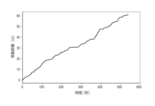
- FIG. 8 is a diagram showing the total traveled distance of worker 400 with respect to time. In FIG. 7, the trajectory of worker 400 is shown superimposed on the captured image for ease of explanation.
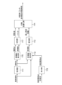
- FIG. 9 is a flowchart showing the operation of the information processing device 100.
- FIG. This flowchart can be executed by the control unit 110 of the information processing apparatus 100 according to a program. Steps S102-S105 may be performed for each frame of the captured image.
- the control unit 110 receives a specification of a specific joint point from the user and identifies the specific joint point (S101).
- the control unit 110 acquires the captured image by receiving it from the imaging device 200 (S102).
- the control unit 110 detects joint points 410 of each worker 400 from the captured image (S103).
- the control unit 110 extracts the color information of the specific joint point from the captured image (S104).
- the control unit 110 identifies each individual worker 400 by identifying the worker ID from the extracted color information, and associates the worker ID with the joint point 410 of each worker 400 (S105).
- the control unit 110 determines whether captured images for a predetermined time have been acquired (S106).
- the predetermined time can be set to any time.
- the predetermined time can be, for example, 10 minutes. If the control unit 110 determines that the captured images for the predetermined time have been acquired (S106: YES), the control unit 110 executes step S107. If the control unit 110 determines that the captured image for the predetermined time has not been acquired (S106: NO), it continues acquiring the captured image until the captured image for the predetermined time is acquired (S102).
- the control unit 110 calculates the movement distance of each worker 400 from the trajectory of each joint point 410 for a predetermined time (S107).
- the control unit 110 outputs the movement distance of each worker 400 in association with each worker 400 (S108).
- FIG. 10 is a block diagram showing functions of the control unit 110 of the information processing device 100.
- Control unit 110 functions as acquisition unit 111, color information extraction unit 112, identification unit 113, behavior quantification unit 114, feature amount calculation unit 116, determination unit 117, and reception unit 115 by executing programs.
- the feature amount calculation unit 116 calculates feature amounts based on the joint points 410 acquired by the acquisition unit 111 .
- the feature amount is a value that can contribute to work determination, and can be any value that can be calculated from the joint points 410 .
- the feature quantity includes, for example, the relative distance between the joint points 410 and the moving speed of the joint points 410 .
- the relative distance between the joint points 410 is, for example, the distance between the elbow joint point 410 and the wrist joint point 410, and can be calculated from each joint point 410 (more specifically, the coordinates of the joint point 410).
- the moving speed of the joint point 410 is, for example, the moving speed of the neck joint point 410b, and can be calculated from the moving distance of the neck joint point 410b between frames of the captured image and the frame rate.
- the discrimination unit 117 discriminates the work performed by the worker 400 in the captured image into a plurality of types of work based on the joint points 410 and the feature amount. For example, the determination unit 117 determines whether the work performed by the worker 400 in the captured image is either direct work or indirect work.
- Direct work is work that is essential for product assembly and the like. Direct work may include work that contributes greatly to product assembly and the like.
- Indirect work is work that accompanies direct work, and includes, for example, work such as throwing away garbage and taking parts out of bags.
- the discrimination unit 117 can discriminate the work performed by the worker 400 into multiple types of work by, for example, associating a work flag that can identify the work with the joint point 410 or the like.
- the work flag may be, for example, a flag that sets "1" for direct work and "0" for indirect work.
- the discrimination unit 117 can be configured using a trained model that has been machine-learned by supervised learning.
- the learned model may be a neural network model that has undergone supervised learning using the task flag of each task as an objective variable and the joint points 410 and the feature values calculated by the feature value calculation unit 116 as explanatory variables.
- As training data a combination of a photographed image and a correct label annotated with a flag indicating direct work as "1" and indirect work as "0" by visually judging the work of the worker 400 in the photographed image. can be used.
- FIG. 11 is a diagram showing joint points 410 together with a photographed image.
- the discrimination unit 117 can also discriminate, with a high degree of accuracy, a plurality of types of work even for work that requires little movement, such as work performed on a desk.
- FIG. 12 is a diagram showing the contents of the analysis result integrated file. Frame IDs, person IDs, joint points 410, work flags, and worker IDs are associated in the analysis result integrated file.
- the work flag that identifies the work of the worker 400 can be added to the analysis result integrated file in association with the joint point 410 or the like after being determined by the determining unit 117 .
- the worker ID After being identified by the identification unit 113 based on the color information of the specific joint point, the worker ID can be added to the analysis result integration file in association with the joint point 410 and the like.
- the discriminating unit 117 discriminates the work performed by the worker 400 in the captured image into a plurality of types of work by unsupervised learning based on the distribution of the joint points 410 respectively acquired from the plurality of time-series frames of the captured image.
- the determination unit 117 may determine the work by clustering based on the distribution of the joint points 410 .
- the distribution range of the joint points 410 is defined for each task by acquiring the distribution of the joint points 410 (for example, the wrist joint points 410) of each worker 400 in advance for each of a plurality of tasks. Then, depending on which distribution range the joint point 410 belongs to, the work may be determined. In addition, not only the distribution of one joint point 410 but also the distribution of a plurality of joint points 410 may be combined to determine the work.
- the behavior quantification unit 114 quantifies the behavior of each worker 400 by calculating the work time for each task for each worker 400 based on the analysis result integrated file.
- the behavior quantification unit 114 can output the work time of each task, which is a quantified value obtained by quantifying the behavior of each worker 400, in association with the worker ID identified by the identification unit 113.
- FIG. 13 is a flowchart showing the operation of the information processing device 100.
- FIG. This flowchart can be executed by the control unit 110 of the information processing apparatus 100 according to a program. Steps S102-S105 may be performed for each frame of the captured image.
- the control unit 110 receives the specification of the specific joint point from the user and identifies the specific joint point (S201).
- the control unit 110 acquires the captured image by receiving it from the imaging device 200 (S202).
- the control unit 110 detects joint points 410 of each worker 400 from the captured image (S203).
- the control unit 110 extracts the color information of the specific joint point from the captured image (S204).
- the control unit 110 identifies each worker 400 by identifying the worker ID from the extracted color information, and associates the worker ID with the joint point 410 of each worker 400 (S205).
- the control unit 110 calculates feature amounts based on the joint points 410 (S206).
- the control unit 110 determines the work from the joint points 410 and the feature amount, and associates the determined work with the joint points 410 (S207).
- the control unit 110 determines whether captured images for a predetermined time have been acquired (S208).
- the predetermined time can be set to any time.
- the predetermined time can be, for example, 10 minutes. If the control unit 110 determines that the captured images for the predetermined time have been acquired (S208: YES), the control unit 110 executes step S209. If the control unit 110 determines that the captured image for the predetermined time has not been acquired (S208: NO), it continues acquiring the captured image until the captured image for the predetermined time is acquired (S202).
- the control unit 110 calculates the work time for each work of each worker 400 based on the work and the worker ID associated with each joint point 410 for a predetermined time (S209).
- the control unit 110 outputs the work time for each work of each worker 400 in association with each worker 400 (S210).
- the predetermined article attached to the workers 400 is described as an article colored with which each worker 400 can be identified.
- the predetermined article may be an IC tag, a chameleon code, or the like.
- the identification unit 113 acquires the position information and the worker ID of the worker 400 attached to the IC tag from the IC tag, converts them into the coordinates of the pixels in the captured image, and identifies the work existing at the converted coordinates.
- the worker 400 is identified by the worker ID.
- the correspondence relationship between the position information of the worker 400 and the coordinates of the pixels in the captured image is acquired in advance by measurement or the like and stored in the storage unit 120. By using this, the position information of the worker 400 can be obtained in the captured image. Can be converted to pixel coordinates.
- the predetermined article is a chameleon code
- the image of the chameleon code is included in the photographed image, so the individual worker 400 can be identified by using the image of the chameleon code.
- the identification unit 113 may identify the individual worker 400 in the captured image using a known face recognition technology. In this case, there is no need for the worker 400 to accompany the predetermined article.
- the embodiment has the following effects.
- the object is identified based on the joint points. This makes it possible to easily and accurately quantify the behavior of each worker.
- the object is identified based on the joint points and the image from which the joint points are acquired. This makes it easier to identify the object to be quantified.
- the quantified value of the behavior of the object is associated with the identified object. This makes it possible to easily grasp the object whose behavior is quantified.
- the joint points attached to the predetermined article are specified, and the color information of the specified joint points is extracted from the image as the color information of the object. Then, the object is identified based on the extracted color information. As a result, an object whose behavior is quantified can be identified with high sensitivity and high accuracy regardless of the angle of view of the image or the orientation of the object in the image.
- the joint point specified by the user is specified as the joint point attached to the predetermined item. This makes it possible to more flexibly and easily set the position of attaching the article for identifying the object.
- an object corresponding to the joint point from which color information whose brightness value is within a predetermined range is extracted is identified.
- an object corresponding to the joint point from which color information whose brightness value is within a predetermined range is extracted is identified.
- the behavior of the object is quantified. This can improve the worker's work in terms of travel distance.
- the timing at which the movement amount increases and the worker's motion when the movement amount increases the worker's work can be effectively improved.
- the feature amount is calculated, and the work performed by the object in the image is classified into multiple types of work based on the joint points and the feature amount.
- the behavior of the object is then quantified for each task identified.
- the work discrimination accuracy can be improved. can improve.
- the work time for each work can be easily obtained, and based on the work time for each work, the need for countermeasures can be determined early. .
- the relative distance between joint points is included in the feature amount. As a result, it is possible to improve the discrimination accuracy of the work based on the image.
- the moving speed of the joint points is included in the feature amount. As a result, it is possible to improve the discrimination accuracy of the work based on the image.
- the task performed by the object is divided into multiple types of tasks by supervised learning with the task flag of each task as the objective variable and the joint points and feature values as explanatory variables. As a result, it is possible to easily and accurately determine the work based on the image.
- unsupervised learning is used to classify the work performed by the object into multiple types of work. As a result, it is possible to easily and accurately determine the work based on the image.
- the present invention is not limited to the embodiments described above.
- part or all of the processing executed by the program in the embodiment may be executed by replacing it with hardware such as a circuit.
- 10 information processing system 100 information processing device, 110 control unit, 111 acquisition unit; 112 color information extraction unit, 113 identification unit, 114 Behavioral Quantification Department, 115 Reception Department, 116 feature quantity calculator, 117 discrimination unit, 120 storage unit, 130 Communication Department, 140 operation display unit, 200 imaging device, 300 communication networks, 400 workers, 410 articulation points, 410a Head articulation points, 410b Neck articulation point.
Landscapes
- Engineering & Computer Science (AREA)
- Theoretical Computer Science (AREA)
- Business, Economics & Management (AREA)
- Physics & Mathematics (AREA)
- General Physics & Mathematics (AREA)
- Human Resources & Organizations (AREA)
- Multimedia (AREA)
- Computer Vision & Pattern Recognition (AREA)
- Strategic Management (AREA)
- Human Computer Interaction (AREA)
- Entrepreneurship & Innovation (AREA)
- Economics (AREA)
- General Health & Medical Sciences (AREA)
- Educational Administration (AREA)
- Development Economics (AREA)
- Health & Medical Sciences (AREA)
- Computing Systems (AREA)
- Marketing (AREA)
- Psychiatry (AREA)
- Software Systems (AREA)
- Medical Informatics (AREA)
- Evolutionary Computation (AREA)
- Artificial Intelligence (AREA)
- Databases & Information Systems (AREA)
- Social Psychology (AREA)
- Game Theory and Decision Science (AREA)
- Operations Research (AREA)
- Quality & Reliability (AREA)
- Tourism & Hospitality (AREA)
- General Business, Economics & Management (AREA)
- General Factory Administration (AREA)
- Image Analysis (AREA)
Priority Applications (3)
| Application Number | Priority Date | Filing Date | Title |
|---|---|---|---|
| US18/722,377 US20250061747A1 (en) | 2021-12-23 | 2022-11-04 | Information processing system, behavior quantification program, and behavior quantification method |
| CN202280083756.XA CN118435248A (zh) | 2021-12-23 | 2022-11-04 | 信息处理系统、行为量化程序以及行为量化方法 |
| JP2023569138A JPWO2023119906A1 (https=) | 2021-12-23 | 2022-11-04 |
Applications Claiming Priority (2)
| Application Number | Priority Date | Filing Date | Title |
|---|---|---|---|
| JP2021209302 | 2021-12-23 | ||
| JP2021-209302 | 2021-12-23 |
Publications (1)
| Publication Number | Publication Date |
|---|---|
| WO2023119906A1 true WO2023119906A1 (ja) | 2023-06-29 |
Family
ID=86902049
Family Applications (1)
| Application Number | Title | Priority Date | Filing Date |
|---|---|---|---|
| PCT/JP2022/041183 Ceased WO2023119906A1 (ja) | 2021-12-23 | 2022-11-04 | 情報処理システム、行動定量化プログラム、および行動定量化方法 |
Country Status (4)
| Country | Link |
|---|---|
| US (1) | US20250061747A1 (https=) |
| JP (1) | JPWO2023119906A1 (https=) |
| CN (1) | CN118435248A (https=) |
| WO (1) | WO2023119906A1 (https=) |
Citations (4)
| Publication number | Priority date | Publication date | Assignee | Title |
|---|---|---|---|---|
| JP2017034511A (ja) * | 2015-08-03 | 2017-02-09 | 株式会社ブイ・アール・テクノセンター | 移動体検出システム |
| JP2017068431A (ja) * | 2015-09-29 | 2017-04-06 | 富士重工業株式会社 | 負担評価装置、負担評価方法 |
| WO2021131552A1 (ja) * | 2019-12-27 | 2021-07-01 | パナソニックIpマネジメント株式会社 | 作業分析装置及び作業分析方法 |
| JP2021131787A (ja) * | 2020-02-21 | 2021-09-09 | 株式会社日立ハイテク | 情報処理装置、および判断結果出力方法 |
Family Cites Families (6)
| Publication number | Priority date | Publication date | Assignee | Title |
|---|---|---|---|---|
| KR20160046082A (ko) * | 2014-10-20 | 2016-04-28 | (주)한국인터넷소프트웨어 | 체력측정/운동처방 서비스 제공 시스템의 체력측정/운동처방 서비스 제공방법 |
| JP7138456B2 (ja) * | 2018-03-09 | 2022-09-16 | 株式会社エヌ・ティ・ティ・データ | 印象導出システム、印象導出方法および印象導出プログラム |
| JP7411405B2 (ja) * | 2019-12-23 | 2024-01-11 | Ntn株式会社 | 軸受装置、スピンドル装置、軸受、および間座 |
| JP7413836B2 (ja) * | 2020-02-28 | 2024-01-16 | 富士通株式会社 | 行動認識方法、行動認識プログラム及び行動認識装置 |
| WO2022024487A1 (ja) * | 2020-07-30 | 2022-02-03 | コニカミノルタ株式会社 | 解析システム、解析システムの制御プログラム、制御プログラム、および解析システムの制御方法 |
| JPWO2023100590A1 (https=) * | 2021-12-03 | 2023-06-08 |
-
2022
- 2022-11-04 JP JP2023569138A patent/JPWO2023119906A1/ja active Pending
- 2022-11-04 US US18/722,377 patent/US20250061747A1/en active Pending
- 2022-11-04 CN CN202280083756.XA patent/CN118435248A/zh active Pending
- 2022-11-04 WO PCT/JP2022/041183 patent/WO2023119906A1/ja not_active Ceased
Patent Citations (4)
| Publication number | Priority date | Publication date | Assignee | Title |
|---|---|---|---|---|
| JP2017034511A (ja) * | 2015-08-03 | 2017-02-09 | 株式会社ブイ・アール・テクノセンター | 移動体検出システム |
| JP2017068431A (ja) * | 2015-09-29 | 2017-04-06 | 富士重工業株式会社 | 負担評価装置、負担評価方法 |
| WO2021131552A1 (ja) * | 2019-12-27 | 2021-07-01 | パナソニックIpマネジメント株式会社 | 作業分析装置及び作業分析方法 |
| JP2021131787A (ja) * | 2020-02-21 | 2021-09-09 | 株式会社日立ハイテク | 情報処理装置、および判断結果出力方法 |
Also Published As
| Publication number | Publication date |
|---|---|
| US20250061747A1 (en) | 2025-02-20 |
| CN118435248A (zh) | 2024-08-02 |
| JPWO2023119906A1 (https=) | 2023-06-29 |
Similar Documents
| Publication | Publication Date | Title |
|---|---|---|
| Seo et al. | Automated postural ergonomic risk assessment using vision-based posture classification | |
| CN109670441B (zh) | 一种实现安全帽穿戴识别的方法、系统、终端以及计算机可读存储介质 | |
| CN111553229B (zh) | 基于三维骨骼与lstm的工人动作识别方法及装置 | |
| CN112287759A (zh) | 基于关键点的跌倒检测方法 | |
| CN104888444B (zh) | 一种卡路里消耗和手部姿势识别的智慧手套、方法及系统 | |
| JP2020046928A (ja) | 情報処理装置、情報処理システム、情報処理方法及びプログラム | |
| CN109598229A (zh) | 基于动作识别的监控系统及其方法 | |
| Singh et al. | Human pose estimation using convolutional neural networks | |
| CN112396658A (zh) | 一种基于视频的室内人员定位方法及定位系统 | |
| CN106778609A (zh) | 一种电力施工现场人员制服穿着识别方法 | |
| JP2020098590A (ja) | 移動物追跡装置 | |
| CN110490171B (zh) | 一种危险姿态识别方法、装置、计算机设备及存储介质 | |
| Zhang et al. | Detection of helmet use among construction workers via helmet-head region matching and state tracking | |
| TW201426227A (zh) | 工序分析監控系統及其方法 | |
| CN107784287A (zh) | 一种检测方法以及装置、计算机装置、可读存储介质 | |
| CN116269355A (zh) | 一种基于人物姿态识别的安全监测系统 | |
| CN114155557A (zh) | 定位方法、装置、机器人及计算机可读存储介质 | |
| CN115909487A (zh) | 一种基于人体姿态检测的儿童步态异常评估辅助系统 | |
| CN113505770B (zh) | 快递行业衣着发饰异常检测方法及系统、电子设备 | |
| CN120279658A (zh) | 基于图像识别的防坠落识别预警方法以及其相关设备 | |
| Wen et al. | Artificial intelligence technologies for more flexible recommendation in uniforms | |
| CN103870814A (zh) | 基于智能相机的非接触式实时眼动识别方法 | |
| CN112949606B (zh) | 工服穿戴状态检测方法、装置、存储介质及电子装置 | |
| EP3922176A1 (en) | Physical health condition image analysis device, method, and system | |
| WO2023119906A1 (ja) | 情報処理システム、行動定量化プログラム、および行動定量化方法 |
Legal Events
| Date | Code | Title | Description |
|---|---|---|---|
| 121 | Ep: the epo has been informed by wipo that ep was designated in this application |
Ref document number: 22910626 Country of ref document: EP Kind code of ref document: A1 |
|
| ENP | Entry into the national phase |
Ref document number: 2023569138 Country of ref document: JP Kind code of ref document: A |
|
| WWE | Wipo information: entry into national phase |
Ref document number: 202280083756.X Country of ref document: CN |
|
| WWE | Wipo information: entry into national phase |
Ref document number: 18722377 Country of ref document: US |
|
| NENP | Non-entry into the national phase |
Ref country code: DE |
|
| 122 | Ep: pct application non-entry in european phase |
Ref document number: 22910626 Country of ref document: EP Kind code of ref document: A1 |