WO2023119552A1 - 空気調和機 - Google Patents
空気調和機 Download PDFInfo
- Publication number
- WO2023119552A1 WO2023119552A1 PCT/JP2021/047857 JP2021047857W WO2023119552A1 WO 2023119552 A1 WO2023119552 A1 WO 2023119552A1 JP 2021047857 W JP2021047857 W JP 2021047857W WO 2023119552 A1 WO2023119552 A1 WO 2023119552A1
- Authority
- WO
- WIPO (PCT)
- Prior art keywords
- heat medium
- refrigerant
- heat
- heat exchanger
- circuit
- Prior art date
Links
- 239000003507 refrigerant Substances 0.000 claims abstract description 512
- XLYOFNOQVPJJNP-UHFFFAOYSA-N water Substances O XLYOFNOQVPJJNP-UHFFFAOYSA-N 0.000 claims abstract description 134
- 238000010438 heat treatment Methods 0.000 description 49
- 238000001816 cooling Methods 0.000 description 19
- 238000010586 diagram Methods 0.000 description 18
- 230000000630 rising effect Effects 0.000 description 17
- 238000001514 detection method Methods 0.000 description 11
- 230000006870 function Effects 0.000 description 10
- 230000005494 condensation Effects 0.000 description 6
- 238000009833 condensation Methods 0.000 description 6
- 238000010276 construction Methods 0.000 description 6
- 238000009434 installation Methods 0.000 description 6
- 238000001704 evaporation Methods 0.000 description 5
- 230000008020 evaporation Effects 0.000 description 5
- 239000007788 liquid Substances 0.000 description 3
- 239000000203 mixture Substances 0.000 description 3
- CDOOAUSHHFGWSA-OWOJBTEDSA-N (e)-1,3,3,3-tetrafluoroprop-1-ene Chemical compound F\C=C\C(F)(F)F CDOOAUSHHFGWSA-OWOJBTEDSA-N 0.000 description 2
- FXRLMCRCYDHQFW-UHFFFAOYSA-N 2,3,3,3-tetrafluoropropene Chemical compound FC(=C)C(F)(F)F FXRLMCRCYDHQFW-UHFFFAOYSA-N 0.000 description 2
- ATUOYWHBWRKTHZ-UHFFFAOYSA-N Propane Chemical compound CCC ATUOYWHBWRKTHZ-UHFFFAOYSA-N 0.000 description 2
- 239000012267 brine Substances 0.000 description 2
- 230000006866 deterioration Effects 0.000 description 2
- HPALAKNZSZLMCH-UHFFFAOYSA-M sodium;chloride;hydrate Chemical compound O.[Na+].[Cl-] HPALAKNZSZLMCH-UHFFFAOYSA-M 0.000 description 2
- 238000011144 upstream manufacturing Methods 0.000 description 2
- -1 R410A Substances 0.000 description 1
- 239000000654 additive Substances 0.000 description 1
- 230000000996 additive effect Effects 0.000 description 1
- 230000002528 anti-freeze Effects 0.000 description 1
- 239000000470 constituent Substances 0.000 description 1
- 239000002826 coolant Substances 0.000 description 1
- 230000000694 effects Effects 0.000 description 1
- 231100000252 nontoxic Toxicity 0.000 description 1
- 230000003000 nontoxic effect Effects 0.000 description 1
- 239000001294 propane Substances 0.000 description 1
- 238000005057 refrigeration Methods 0.000 description 1
- 239000007787 solid Substances 0.000 description 1
- 239000000126 substance Substances 0.000 description 1
Images


Classifications
-
- F—MECHANICAL ENGINEERING; LIGHTING; HEATING; WEAPONS; BLASTING
- F24—HEATING; RANGES; VENTILATING
- F24H—FLUID HEATERS, e.g. WATER OR AIR HEATERS, HAVING HEAT-GENERATING MEANS, e.g. HEAT PUMPS, IN GENERAL
- F24H4/00—Fluid heaters characterised by the use of heat pumps
- F24H4/02—Water heaters
-
- F—MECHANICAL ENGINEERING; LIGHTING; HEATING; WEAPONS; BLASTING
- F25—REFRIGERATION OR COOLING; COMBINED HEATING AND REFRIGERATION SYSTEMS; HEAT PUMP SYSTEMS; MANUFACTURE OR STORAGE OF ICE; LIQUEFACTION SOLIDIFICATION OF GASES
- F25B—REFRIGERATION MACHINES, PLANTS OR SYSTEMS; COMBINED HEATING AND REFRIGERATION SYSTEMS; HEAT PUMP SYSTEMS
- F25B1/00—Compression machines, plants or systems with non-reversible cycle
-
- F—MECHANICAL ENGINEERING; LIGHTING; HEATING; WEAPONS; BLASTING
- F25—REFRIGERATION OR COOLING; COMBINED HEATING AND REFRIGERATION SYSTEMS; HEAT PUMP SYSTEMS; MANUFACTURE OR STORAGE OF ICE; LIQUEFACTION SOLIDIFICATION OF GASES
- F25B—REFRIGERATION MACHINES, PLANTS OR SYSTEMS; COMBINED HEATING AND REFRIGERATION SYSTEMS; HEAT PUMP SYSTEMS
- F25B6/00—Compression machines, plants or systems, with several condenser circuits
- F25B6/02—Compression machines, plants or systems, with several condenser circuits arranged in parallel
-
- F—MECHANICAL ENGINEERING; LIGHTING; HEATING; WEAPONS; BLASTING
- F25—REFRIGERATION OR COOLING; COMBINED HEATING AND REFRIGERATION SYSTEMS; HEAT PUMP SYSTEMS; MANUFACTURE OR STORAGE OF ICE; LIQUEFACTION SOLIDIFICATION OF GASES
- F25B—REFRIGERATION MACHINES, PLANTS OR SYSTEMS; COMBINED HEATING AND REFRIGERATION SYSTEMS; HEAT PUMP SYSTEMS
- F25B7/00—Compression machines, plants or systems, with cascade operation, i.e. with two or more circuits, the heat from the condenser of one circuit being absorbed by the evaporator of the next circuit
Definitions
- the present disclosure relates to an air conditioner having a hot water storage tank.
- Patent Document 1 discloses a configuration in which water stored in a hot water storage tank is efficiently heated to a high temperature by a water temperature raising device that uses two types of refrigerants with different condensation temperatures. .
- air conditioners require a pump to convey heated water to the hot water storage tank.
- the pump of the air conditioner disclosed in Patent Document 1 is provided in a pipe that connects the water heater and the hot water storage tank. For this reason, in Patent Document 1, the pump had to be attached when the hot water storage tank was constructed, which increased the on-site work cost.
- the present disclosure is intended to solve the above problems, and aims to provide an air conditioner that omits installation of a pump during construction and reduces on-site work costs.
- An air conditioner includes an outdoor unit having a first compressor that circulates a first refrigerant in a first refrigerant circuit, an outdoor heat exchanger through which the first refrigerant flows, and a refrigerant heat exchanger through which the first refrigerant flows.
- a refrigerant indoor unit a first pump that circulates a heat medium different from the first refrigerant in the first heat medium circuit, and a first heat medium that exchanges heat between the first refrigerant and the heat medium that circulates in the first heat medium circuit
- a first relay machine having one relay heat exchanger, a second pump that circulates a heat medium different from the first refrigerant in the second heat medium circuit, and a heat medium that circulates through the first refrigerant and the second heat medium circuit a first heat medium indoor unit having a first heat medium heat exchanger through which the heat medium circulating in the first heat medium circuit flows; a hot water storage tank in which the heat medium circulating in the heat medium circuit is stored.
- the repeater has a pump. Therefore, there is no need to install a pump in the pipe connecting the repeater and the hot water tank. Therefore, according to the air conditioner of the present disclosure, it is possible to omit the installation of the pump when constructing the hot water storage tank, and reduce the on-site work cost.
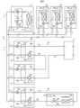
- FIG. 1 is a circuit diagram of an air conditioner according to Embodiment 1.
- FIG. FIG. 4 is a circuit diagram of an air conditioner according to Embodiment 2;
- FIG. 10 is a circuit diagram of an air conditioner according to Embodiment 3;
- FIG. 11 is a circuit diagram of an air conditioner according to Embodiment 4;
- FIG. 11 is a diagram showing operating points of a refrigerant circuit according to Embodiment 4 on a Ph diagram.
- FIG. 11 is a circuit diagram of an air conditioner according to Embodiment 5;
- FIG. 11 is a circuit diagram of an air conditioner according to Embodiment 6;
- FIG. 11 is a circuit diagram of an air conditioner according to Embodiment 7;
- FIG. 1 is a circuit diagram of an air conditioner according to Embodiment 1.
- the air conditioner 100 of Embodiment 1 air-conditions a plurality of air-conditioned spaces in a building such as a building.
- the air conditioner 100 includes an outdoor unit 1, a plurality of refrigerant indoor units 2a to 2c, a heat medium indoor unit 3a, and a repeater connected between the outdoor unit 1 and the heat medium indoor unit 3a.
- the repeaters 4a and 4b perform heat exchange between the refrigerant supplied from the outdoor unit 1 and the heat medium.
- the repeaters 4a and 4b correspond to the "first repeater" and the "second repeater” of the present disclosure, respectively.
- the heat medium indoor unit 3a corresponds to the "first heat medium indoor unit” of the present disclosure.
- the outdoor unit 1 and the refrigerant indoor units 2a to 2c, and the outdoor unit 1 and the relay unit 4 are connected by refrigerant pipes 65 and 66 through which the refrigerant flows.
- the refrigerant indoor units 2a to 2c and the repeater 4 are connected in parallel to the outdoor unit 1.
- FIG. Further, the repeater 4a and the heat medium indoor unit 3a are connected by heat medium pipes 71a and 72a through which the heat medium flows.
- the repeater 4b and the hot water storage tank 6 are connected by heat medium pipes 73 and 74 through which the heat medium flows.
- the heat generated in the outdoor unit 1 is transferred to the refrigerant indoor units 2a to 2c and the repeaters 4a and 4b by the refrigerant flowing through the refrigerant pipes 65 and 66.
- the heat exchanged by the repeater 4a is transferred to the heat medium indoor unit 3a by the heat medium flowing through the heat medium pipe 71a.
- the refrigerant indoor units 2a to 2c of the air conditioner 100 directly cool or heat the air-conditioned space with the refrigerant supplied from the outdoor unit 1.
- the heat medium indoor unit 3a cools or heats the air-conditioned space with a heat medium to which heat is transferred from the refrigerant supplied from the outdoor unit 1.
- the air conditioner 100 includes both a refrigerant indoor unit that directly uses the refrigerant supplied from the outdoor unit 1 and a heat medium indoor unit that indirectly uses the refrigerant.
- the hot water storage tank 6 stores the heat medium heated by the refrigerant supplied from the outdoor unit 1 .
- the hot water storage tank 6 includes a pipe for supplying the heat medium before heating from the outside of the air conditioner 100 to the hot water storage tank 6, and a pipe for supplying the heated heat medium from the hot water storage tank 6 to the utilization side.
- a pipe is attached to supply the
- the refrigerant used in the air conditioner 100 is, for example, a single refrigerant such as R32, a pseudo-azeotropic mixed refrigerant such as R410A, or a refrigerant containing a double bond or CF 3 I in the chemical formula. refrigerants or mixtures thereof, natural refrigerants such as CF 3 I, CO 2 or propane.
- the heat medium used in the heat medium indoor unit 3a is, for example, water, brine (antifreeze), a mixture of brine and water, or a mixture of water and an additive having a high anticorrosion effect.
- the heat medium stored in the hot water storage tank 6 is, for example, water.
- the "heat medium" in the present disclosure is a heat medium other than a refrigerant and is non-toxic and non-flammable.
- the outdoor unit 1 includes a compressor 11, a channel switching valve 12, an outdoor heat exchanger 13, an outdoor fan 14, an accumulator 15, an outdoor refrigerant pipe 16, and an outdoor control device 17.
- the compressor 11 sucks a low-temperature, low-pressure gas refrigerant, compresses it, and discharges a high-temperature, high-pressure gas refrigerant.
- the compressor 11 is, for example, an inverter type compressor whose capacity is controllable. Compressor 11 is equivalent to the "1st compressor" of this indication.
- the channel switching valve 12 is, for example, a four-way valve.
- the flow path switching valve 12 switches the flow path of the refrigerant discharged from the compressor 11 according to the operation of the refrigerant indoor units 2a to 2c and the heat medium indoor unit 3a.
- the flow path switching valve 12 switches to the flow path indicated by the solid line in FIG. 1 during the heating operation, and switches to the flow path indicated by the broken line in FIG. 1 during the cooling operation.
- the channel switching valve 12 may be a combination of a three-way valve and a two-way valve.
- the outdoor heat exchanger 13 is, for example, a fin-tube heat exchanger.
- the outdoor heat exchanger 13 exchanges heat between the air supplied by the outdoor fan 14 and the refrigerant.
- the outdoor heat exchanger 13 functions as a condenser during cooling operation, and condenses and liquefies the refrigerant.
- the outdoor heat exchanger 13 functions as an evaporator during heating operation, and evaporates and gasifies the refrigerant.
- the outdoor fan 14 is, for example, a propeller fan.
- the outdoor fan 14 supplies air around the outdoor unit 1 to the outdoor heat exchanger 13 .
- the accumulator 15 is provided on the suction side of the compressor 11 and has a function of separating liquid refrigerant and gas refrigerant and a function of storing excess refrigerant.
- the outdoor refrigerant pipe 16 is a pipe inside the housing (not shown) of the outdoor unit 1 among the pipes through which the refrigerant of the air conditioner 100 flows.
- the outdoor refrigerant pipe 16 connects the outdoor heat exchanger 13, the accumulator 15, the compressor 11, and the flow path switching valve 12 in this order.
- the end portion of the outdoor refrigerant pipe 16 on the flow path switching valve 12 side is connected to the refrigerant pipe 65 .
- the outdoor heat exchanger 13 side end of the outdoor refrigerant pipe 16 is connected to the refrigerant pipe 66 .
- the outdoor control device 17 controls the operations of the compressor 11, the flow path switching valve 12, and the outdoor fan 14.
- the outdoor control device 17 is composed of a processing device having a memory for storing data and programs necessary for control and a CPU for executing the program, dedicated hardware such as ASIC or FPGA, or both.
- the outdoor control device 17 drives the compressor 11 based on the detection results of a pressure sensor (not shown) that detects the refrigerant pressure and a temperature sensor (not shown) that detects the refrigerant temperature or the outside air temperature mounted on the outdoor unit 1.
- the frequency, the flow path of the flow path switching valve 12, and the rotational speed of the outdoor fan 14 are controlled.
- the outdoor control device 17 includes indoor control devices 25a to 25c mounted on the refrigerant indoor units 2a to 2c, an indoor control device 35a mounted on the heat medium indoor unit 3a, and a relay control device mounted on the repeaters 4a and 4b. Data communication can occur between 46a and 46b.
- the refrigerant indoor units 2a to 2c supply the heat generated by the outdoor unit 1 to the cooling load or heating load of the air-conditioned space.
- the refrigerant indoor unit 2a includes a refrigerant heat exchanger 21a, an expansion valve 22a, an indoor fan 23a, an indoor refrigerant pipe 24a, and an indoor controller 25a.
- the refrigerant heat exchanger 21a is, for example, a fin-tube heat exchanger.
- the refrigerant heat exchanger 21a exchanges heat between the refrigerant and the air supplied by the indoor fan 23a.
- the refrigerant heat exchanger 21a functions as a condenser during heating operation, and condenses and liquefies the refrigerant. Further, the refrigerant heat exchanger 21a functions as an evaporator during cooling operation, and evaporates the refrigerant to gasify it.
- the expansion valve 22a is an electronic expansion valve whose opening degree is variably controlled.
- the expansion valve 22a is connected in series with the refrigerant heat exchanger 21a, and decompresses and expands the refrigerant flowing out of the refrigerant heat exchanger 21a or flowing into the refrigerant heat exchanger 21a.
- the indoor fan 23a is, for example, a cross-flow fan.
- the indoor fan 23a supplies air in the air-conditioned space to the refrigerant heat exchanger 21a.
- the condensing ability or evaporation ability of the refrigerant heat exchanger 21a is controlled by controlling the rotational speed of the indoor fan 23a by the indoor controller 25a.
- the indoor refrigerant pipe 24a is a pipe inside the housing (not shown) of the refrigerant indoor unit 2a among the pipes through which the refrigerant of the air conditioner 100 flows.
- the indoor refrigerant pipe 24a connects the refrigerant heat exchanger 21a and the expansion valve 22a.
- An end of the indoor refrigerant pipe 24 a on the refrigerant heat exchanger 21 a side is connected to the refrigerant pipe 65 .
- the end of the indoor refrigerant pipe 24 a on the expansion valve 22 a side is connected to the refrigerant pipe 66 .
- the indoor controller 25a controls the operation of the expansion valve 22a and the indoor fan 23a.
- the indoor control device 25a is composed of a processing device having a memory for storing data and programs necessary for control and a CPU for executing the program, dedicated hardware such as ASIC or FPGA, or both.
- the indoor controller 25a operates the expansion valve based on the detection results of a temperature sensor (not shown) that detects the temperature of the air-conditioned space and a temperature sensor (not shown) that detects the temperature of the refrigerant at the outlet and inlet of the refrigerant indoor unit 2a. 22a and the rotational speed of the indoor fan 23a are controlled.
- a temperature sensor is, for example, a thermistor.
- the indoor controller 25a controls the opening degree of the expansion valve 22a and the rotational speed of the indoor fan 23a, for example, according to the difference between the temperature of the air-conditioned space and the target temperature.
- the refrigerant indoor units 2b and 2c have the same configuration as the refrigerant indoor unit 2a. That is, the refrigerant indoor unit 2b includes a refrigerant heat exchanger 21b, an expansion valve 22b, an indoor fan 23b, an indoor refrigerant pipe 24b, and an indoor controller 25b. Similarly, the refrigerant indoor unit 2c includes a refrigerant heat exchanger 21c, an expansion valve 22c, an indoor fan 23c, an indoor refrigerant pipe 24c, and an indoor controller 25c. Since the configuration of each device of the refrigerant indoor units 2b and 2c is the same as that of the refrigerant indoor unit 2a, the explanation is omitted.
- the heat medium indoor unit 3a supplies the heat converted by the repeater 4a to the cooling load or heating load of the air-conditioned space.
- the heat medium indoor unit 3a includes a heat medium heat exchanger 31a, a flow control valve 32a, an indoor fan 33a, an indoor heat medium pipe 34a, and an indoor controller 35a.
- the heat medium heat exchanger 31a is, for example, a fin-tube heat exchanger.
- the heat medium heat exchanger 31a exchanges heat between the air supplied by the indoor fan 33a and the heat medium.
- the heat medium heat exchanger 31a corresponds to the "first heat medium heat exchanger" of the present disclosure.
- the flow control valve 32a is an electromagnetic valve whose opening degree is variably controlled.
- the flow control valve 32a is connected in series with the heat medium heat exchanger 31a and adjusts the flow rate of the heat medium flowing through the heat medium heat exchanger 31a.
- the indoor fan 33a is, for example, a cross-flow fan.
- the indoor fan 33a supplies air in the air-conditioned space to the heat medium heat exchanger 31a.
- the heating capacity or cooling capacity of the heat medium heat exchanger 31a is controlled by controlling the rotational speed of the indoor fan 33a by the indoor controller 35a.
- the indoor heat medium pipe 34a is a pipe that connects the heat medium heat exchanger 31a and the flow control valve 32a.
- the indoor heat medium pipe 34a is a pipe inside the housing (not shown) of the refrigerant indoor unit 2a among the pipes through which the heat medium of the air conditioner 100 flows.
- the end of the indoor heat medium pipe 34a on the heat medium heat exchanger 31 side is connected to the heat medium pipe 71a.
- the end on the side of the flow control valve 32a is connected to the heat medium pipe 72a.
- the indoor controller 35a controls the operation of the flow rate adjustment valve 32a and the indoor fan 33a.
- the indoor control device 35a is composed of a processing device having a memory for storing data and programs necessary for control and a CPU for executing the program, dedicated hardware such as ASIC or FPGA, or both.
- a temperature sensor (not shown) that detects the temperature of the air-conditioned space and a temperature sensor (not shown) that detects the temperature of the heat medium at the outlet and inlet of the heat medium indoor unit 3a, It controls the opening degree of the flow control valve 32a and the rotation speed of the indoor fan 33a.
- a temperature sensor is, for example, a thermistor.
- the indoor controller 35a controls the opening degree of the flow control valve 32a and the rotational speed of the indoor fan 33a, for example, according to the difference between the temperature of the air-conditioned space and the target temperature.
- the indoor control device 35a uses the detection result of a pressure sensor (not shown) attached to the front and rear of the flow control valve 32a and the Cv value corresponding to the opening degree of the flow control valve 32a stored in advance to determine the heat medium may be calculated, and the opening degree of the flow control valve 32a may be controlled based on the calculation result.
- the relay machine 4a includes a relay heat exchanger 41a, an expansion valve 42a, a pump 43a, a relay refrigerant pipe 44a, a relay heat medium pipe 45a, and a relay control device 46a.
- the relay heat exchanger 41a is, for example, a plate heat exchanger.
- the relay heat exchanger 41a has a refrigerant channel (not shown) through which the refrigerant supplied from the outdoor unit 1 flows, and a heat medium channel (not shown) through which the heat medium circulated by the pump 43a flows.
- the relay heat exchanger 41a exchanges heat between the refrigerant flowing through the refrigerant channel and the heat medium flowing through the heat medium channel.
- the relay heat exchanger 41a functions as a condenser during heating operation, and condenses and liquefies the refrigerant. Further, the relay heat exchanger 41a functions as an evaporator during cooling operation, and evaporates the refrigerant to gasify it.
- the expansion valve 42a is an electronic expansion valve whose opening degree is variably controlled.
- the expansion valve 42a is connected in series with the refrigerant flow path of the relay heat exchanger 41a, and decompresses and expands the refrigerant flowing out of the relay heat exchanger 41a or flowing into the relay heat exchanger 41a.
- the pump 43a is, for example, an inverter-type centrifugal pump whose capacity is controllable.
- the pump 43a has a motor driven by an inverter, and is driven using the motor as a power source to apply pressure to the heat medium flowing through the heat medium flow path of the relay heat medium pipe 45b.
- the pump 43a is arranged so that the flow of the refrigerant and the flow of the heat medium during the cooling operation are opposed to each other. They may be arranged for opposing heating counterflow.
- the pump 43a is provided inside the repeater 4a, and is not provided in the heat medium pipes 71a and 72a connecting the repeater 4a and the heat medium indoor unit 3a.
- the relay refrigerant pipe 44a is a pipe inside the housing (not shown) of the relay device 4a among the pipes through which the refrigerant of the air conditioner 100 flows.
- the relay refrigerant pipe 44a connects the refrigerant flow path of the relay heat exchanger 41a and the expansion valve 42a.
- the relay heat exchanger 41 a side end of the relay refrigerant pipe 44 a is connected to the refrigerant pipe 65 .
- the end of the relay refrigerant pipe 44 a on the expansion valve 42 a side is connected to the refrigerant pipe 66 .
- the relay heat medium pipe 45a is a pipe inside the housing of the repeater 4a among the pipes through which the heat medium of the air conditioner 100 flows.
- the relay heat medium pipe 45a connects the heat medium flow path of the relay heat exchanger 41a and the pump 43a.
- the end of the relay heat medium pipe 45a on the side of the relay heat exchanger 41a is connected to the heat medium pipe 71a.
- the pump 43a side end of the relay heat medium pipe 45a is connected to the heat medium pipe 72a.
- the relay control device 46a controls the operations of the expansion valve 42a and the pump 43a.
- the relay control device 46a is composed of a processing device having a memory for storing data and programs required for control and a CPU for executing the program, dedicated hardware such as ASIC or FPGA, or both.
- the relay control device 46a controls the opening degree of the expansion valve 42a based on the detection result of a temperature sensor (not shown) that detects the refrigerant temperature at the refrigerant-side outlet and inlet of the relay heat exchanger 41a.
- the relay control device 46a may control the opening degree of the expansion valve 42a according to the operating capacity of the heat medium indoor unit 3a.
- the relay control device 46a may perform data communication with the indoor control device 25a and control the expansion valves 42a in conjunction with the expansion valves 22a mounted on the refrigerant indoor units 2a to 2c.
- the relay control device 46a detects the pressure of the heat medium attached to the outlet and inlet of the pump 43a, and the pressure sensor (not shown) that detects the pressure of the heat medium. It controls the driving frequency of 43a.
- the relay control device 46a may control the drive frequency of the pump 43a according to the operating capacity of the heat medium indoor unit 3a.
- the repeater 4b has the same configuration as the repeater 4a. That is, the relay 4b includes a relay heat exchanger 41b, an expansion valve 42b, a pump 43b, a relay refrigerant pipe 44b, a relay heat medium pipe 45b, and a relay control device 46b. Since the configuration of each device of the repeater 4b is the same as that of the repeater 4a, the explanation is omitted.
- the pump 43b is provided inside the repeater 4b and is not provided in the heat medium pipe 73 or 74 connecting the repeater 4b and the hot water storage tank 6.
- the relay heat exchangers 41a and 41b respectively correspond to the "first relay heat exchanger” and the "second relay heat exchanger” of the present disclosure.
- the pumps 43a and 43b respectively correspond to the "first pump” and the "second pump” of the present disclosure.
- the repeater 4b is connected to the hot water storage tank 6 unlike the repeater 4a. That is, the end portion of the relay refrigerant pipe 44 b on the side of the relay heat exchanger 41 b is connected to the heat medium pipe 73 . Similarly, the pump 43 b side end of the relay refrigerant pipe 44 b is connected to the heat medium pipe 74 .
- the relay control device 46b controls the opening degree of the expansion valve 42b and the driving of the pump 43b so that the temperature of the heat medium supplied to the hot water storage tank 6 through the heat medium pipe 73 reaches the required temperature.
- the sensors include a temperature sensor (not shown) for detecting the refrigerant temperature at the refrigerant-side outlet and inlet of the relay heat exchanger 41b, and a heat-medium temperature at the heat-medium-side outlet and inlet of the relay heat exchanger 41b.
- a temperature sensor (not shown) or the like is used.
- the required temperature of the heat medium is, for example, set based on an instruction from a remote controller (not shown) or the like for the hot water storage tank 6, and is a temperature obtained from the outlet hot water temperature desired by the user. Further, when the air conditioner 100 performs cooling operation, the relay control device 46b fixes the opening degree of the expansion valve 42b to fully closed, and stops driving the pump 43b.
- the air conditioner 100 includes a refrigerant circuit 91 through which a refrigerant circulates, and heat medium circuits 93 and 94 through which a heat medium circulates.
- the refrigerant circuit 91 includes the compressor 11 of the outdoor unit 1, the flow path switching valve 12, the outdoor heat exchanger 13, and the accumulator 15, the refrigerant heat exchangers 21a to 21c of the refrigerant indoor units 2a to 2c, and the expansion valves 22a to 22c, the refrigerant passages of the relay heat exchangers 41a and 41b of the relays 4a and 4b, and the expansion valves 42a and 42b are connected to the outdoor refrigerant pipe 16, the indoor refrigerant pipes 24a to 24c, the relay refrigerant pipes 44a and 44b, and It is configured to be connected by refrigerant pipes 65 and 66 .
- the compressor 11 circulates the refrigerant within the refrigerant circuit 91 .
- the refrigerant circuit 91 corresponds to the "first refrigerant circuit" of the present disclosure, and the refrigerant flowing through the refrigerant circuit 91 corresponds to the "first refrigerant" of the present disclosure.
- the heat medium flow path and the pump 43a of the relay heat exchanger 41a of the repeater 4a and the heat medium heat exchanger 31a and the flow control valve 32a of the heat medium indoor unit 3a are connected by the heat medium pipes 71a and 72a. Connected and configured.
- the pump 43 a circulates the heat medium in the heat medium circuit 93 .
- the heat medium circuit 93 corresponds to the "first heat medium circuit" of the present disclosure.
- the heat medium circuit 94 is configured by connecting the heat medium side of the relay heat exchanger 41b of the repeater 4b, the pump 43b, and the hot water storage tank 6 with heat medium pipes 73 and 74.
- the pump 43 b circulates the heat medium in the heat medium circuit 94 .
- the heat medium circuit 94 corresponds to the "second heat medium circuit" of the present disclosure.
- the air conditioner 100 performs cooling operation or heating operation based on instructions from a remote controller (not shown) or the like for the refrigerant indoor units 2a to 2c and the heat medium indoor unit 3a. Cooling operation and heating operation are realized by switching the channel switching valve 12 of the outdoor unit 1 . Solid arrows in FIG. 2 indicate the flow of refrigerant during heating operation, and broken arrows indicate the flow of refrigerant during cooling operation. The refrigerant flow in each operation will be described below.
- the high-temperature and high-pressure gas refrigerant discharged from the compressor 11 flows out from the outdoor unit 1 through the flow path switching valve 12, and flows through the refrigerant pipe 65 to the refrigerant indoor units 2a to 2c and the relay machine. 4a and 4b.
- the refrigerant that has flowed into the refrigerant indoor units 2a to 2c exchanges heat with the air supplied by the indoor fans 23a to 23c in the refrigerant heat exchangers 21a to 21c, and is condensed and liquefied.
- the refrigerant dissipates heat to the air in the air-conditioned space, thereby heating the air-conditioned spaces in which the refrigerant indoor units 2a to 2c are installed.
- the refrigerant flowing out of the refrigerant heat exchangers 21a-21c is depressurized by the expansion valves 22a-22c, flows out of the refrigerant indoor units 2a-2c, and flows into the outdoor unit 1 through the refrigerant pipe 66.
- the refrigerant that has flowed into the relay 4a exchanges heat with the heat medium circulated by the pump 43a in the relay heat exchanger 41a, condenses, and liquefies. At this time, the refrigerant radiates heat to the heat medium, thereby heating the heat medium.
- the refrigerant flowing out of the relay heat exchanger 41a is decompressed by the expansion valve 42a, flows out of the relay machine 4a, joins the refrigerant flowing out of the refrigerant indoor units 2a to 2c in the refrigerant pipe 66, and flows into the outdoor unit 1.
- the refrigerant that has flowed into the relay 4b exchanges heat with the heat medium circulated by the pump 43b in the relay heat exchanger 41b, condenses, and liquefies. At this time, the refrigerant radiates heat to the heat medium, thereby heating the heat medium.
- the refrigerant flowing out of the relay heat exchanger 41b is decompressed by the expansion valve 42b, flows out of the relay machine 4b, joins the refrigerant flowing out of the refrigerant indoor units 2b to 2c in the refrigerant pipe 66, and flows into the outdoor unit 1.
- the refrigerant that has flowed into the outdoor unit 1 flows into the outdoor heat exchanger 13 .
- the refrigerant that has flowed into the outdoor heat exchanger 13 exchanges heat with the air supplied by the outdoor fan 14 to evaporate and gasify.
- the refrigerant that has flowed out of the outdoor heat exchanger 13 is sucked into the compressor 11 again via the flow path switching valve 12 and the accumulator 15 .
- the heat medium heated by the relay heat exchanger 41a flows into the heat medium indoor unit 3a through the heat medium pipe 71a.
- the heat medium that has flowed into the heat medium indoor unit 3a exchanges heat with the air supplied by the indoor fan 33a in the heat medium heat exchanger 31a.
- the heat medium radiates heat to the air in the air-conditioned space, thereby heating the air-conditioned space in which the heat medium indoor unit 3a is installed.
- the heat medium that has flowed out of the heat medium heat exchanger 31a passes through the flow control valve 32a, flows out of the heat medium indoor unit 3a, and flows through the heat medium pipe 6b into the repeater 4a.
- the heat medium heated by the relay heat exchanger 41b passes through the heat medium pipe 73 and is stored in the hot water storage tank 6 .
- the heat medium that has not been supplied to the user side flows through the heat medium pipe 74 into the repeater 4b.
- the heat medium supplied to the hot water tank 6 from the outside is heated by circulating through the heat medium circuit 94 and stored in the hot water tank 6 .
- the high-temperature and high-pressure gas refrigerant discharged from the compressor 11 passes through the flow path switching valve 12 and flows into the outdoor heat exchanger 13 .
- the refrigerant that has flowed into the outdoor heat exchanger 13 exchanges heat with the air supplied by the outdoor fan 14, condenses, and liquefies.
- Refrigerant flowing out of the outdoor heat exchanger 13 passes through the refrigerant pipe 66 and is split between the refrigerant indoor units 2a to 2c and the repeaters 4a and 4b.
- the refrigerant that has flowed into the refrigerant indoor units 2a to 2c is decompressed by the expansion valves 22a to 22c, becomes a low-temperature gas-liquid two-phase refrigerant, and flows into the refrigerant heat exchangers 21a to 21c.
- the refrigerant that has flowed into the refrigerant heat exchangers 21a-21c exchanges heat with the air supplied by the indoor fans 23a-23c, evaporates, and becomes gas.
- the air-conditioned spaces in which the refrigerant indoor units 2a to 2c are installed are cooled by the refrigerant absorbing heat from the air in the air-conditioned spaces.
- the refrigerant that has flowed out of the refrigerant heat exchanger 21 a flows into the outdoor unit 1 through the refrigerant pipe 65 .
- the refrigerant that has flowed into the relay 4a is decompressed by the expansion valve 42a, becomes a low-temperature gas-liquid two-phase refrigerant, and flows into the relay heat exchanger 41a.
- the refrigerant that has flowed into the relay heat exchanger 41a exchanges heat with the heat medium circulated by the pump 43a, evaporates, and gasifies. At this time, the heat medium is cooled by the refrigerant absorbing heat from the heat medium.
- the refrigerant flowing out of the relay heat exchanger 41a joins the refrigerant flowing out of the refrigerant indoor units 2a to 2c in the refrigerant pipe 65 and flows into the outdoor unit 1.
- the refrigerant that has flowed into the outdoor unit 1 is sucked into the compressor 11 again via the flow path switching valve 12 and the accumulator 15 .
- the heat medium cooled by the relay heat exchanger 41a flows into the heat medium indoor unit 3a through the heat medium pipe 6a.
- the heat medium that has flowed into the heat medium indoor unit 3a exchanges heat with the air supplied by the indoor fan 33a in the heat medium heat exchanger 31a.
- the heat medium absorbs heat from the air in the air-conditioned space, thereby cooling the air-conditioned space in which the heat medium indoor unit 3a is installed.
- the heat medium that has flowed out of the heat medium heat exchanger 31a passes through the flow control valve 32a, flows out of the heat medium indoor unit 3a, and flows through the heat medium pipe 6b into the repeater 4a.
- the opening degree of the expansion valve 42b is fixed to fully closed, and the driving of the pump 43b is stopped. Therefore, in the relay heat exchanger 41b of the relay device 4b during the cooling operation, substantially no heat exchange occurs between the refrigerant circulating in the refrigerant circuit 91 and the heat medium circulating in the heat medium circuit 94. not.
- the repeater 4b has the pump 43b. Therefore, there is no need to provide a pump for the heat medium pipes 73 and 74 connecting the relay 4b and the hot water storage tank 6.
- FIG. Therefore, according to the air conditioner 100 of Embodiment 1, it is possible to omit the installation of the pump at the time of construction of the hot water storage tank 6, thereby reducing the on-site work cost.
- the air conditioner 100 of Embodiment 1 includes not only the refrigerant indoor units 2a to 2c and the hot water storage tank 6, but also the heat medium indoor unit 3a as load-side devices. Therefore, the occurrence of energy loss in the air conditioner 100 as a whole is suppressed. Further, in the heat medium indoor unit 3a provided with the heat medium heat exchanger 31a, there is no need to prepare for refrigerant leakage in the room.
- the refrigerant charge amount can be reduced.
- the air conditioner 100 of Embodiment 1 it is possible to select the form of the indoor unit from the viewpoint of energy saving performance and necessity of safety measures.
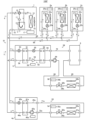
- FIG. 2 is a circuit diagram of the air conditioner 100A according to the second embodiment. As shown in FIG. 2, the second embodiment differs from the first embodiment in that an air conditioner 100A has a repeater 4c. In the second embodiment, the same reference numerals are assigned to the same parts as in the first embodiment, and the description thereof is omitted.
- the repeater 4c is connected in series with the repeater 4b and the hot water storage tank 6. Specifically, the repeater 4b and the hot water storage tank 6 are connected by a heat medium pipe 73 through which the heat medium flows. The hot water storage tank 6 and the repeater 4c are connected by a heat medium pipe 75 through which a heat medium flows. Furthermore, the repeater 4c and the repeater 4b are connected by a heat medium pipe 76 through which a heat medium flows.
- the repeater 4c has the same configuration as the repeaters 4a and 4b. That is, the relay machine 4c includes a relay heat exchanger 41c, an expansion valve 42c, a pump 43c, a relay refrigerant pipe 44c, a relay heat medium pipe 45c, and a relay control device 46c.
- the configuration of each device included in the repeater 4c is the same as that of each device of the repeaters 4a and 4b, so the description is omitted.
- the repeater 4c corresponds to the "third repeater” of the present disclosure.
- the relay heat exchanger 41c corresponds to the "third relay heat exchanger” of the present disclosure.
- the pump 43c corresponds to the "third pump” of the present disclosure.
- the relay heat medium pipes 45b and 45c of the repeaters 4b and 4c are connected to the heat medium pipes 73, 75 and 76 as follows. That is, the end of the relay heat medium pipe 45 b on the side of the relay heat exchanger 41 b is connected to the heat medium pipe 73 . Similarly, the pump 43 b side end of the relay heat medium pipe 45 b is connected to the heat medium pipe 76 . Also, the end of the relay heat medium pipe 45 c on the side of the relay heat exchanger 41 c is connected to the heat medium pipe 76 . Similarly, the pump 43 c side end of the relay heat medium pipe 45 c is connected to the heat medium pipe 75 .
- the relay control device 46c controls the opening degree of the expansion valve 42c and the driving of the pump 43c so that the temperature of the heat medium supplied to the hot water storage tank 6 through the heat medium pipe 73 reaches the required temperature.
- the sensors include a temperature sensor (not shown) that detects the refrigerant temperature at the refrigerant-side outlet and inlet of the relay heat exchanger 41c, and a heat-medium temperature at the heat-medium-side outlet and inlet of the relay heat exchanger 41c.
- a temperature sensor (not shown) or the like is used.
- relay control devices 46b and 46c perform data communication with each other and perform control to interlock the expansion valves 42b and 42c and the pumps 43b and 43c. Specifically, when the load is light, that is, when the required temperature for the hot water storage tank 6 is low, only one of the pumps 43b and 43c is driven. On the other hand, when the load is large, that is, when the required temperature for the hot water storage tank 6 is high, both the pumps 43b and 43c are driven at 100% output, for example.
- expansion is performed so as to reduce this difference. It adjusts the opening of the valves 42b and 42c and the distribution of the outputs of the pumps 43b and 43c.
- inlet/outlet temperature differences ⁇ Tr_b and ⁇ Tr_c are the detection results of the temperature sensors that detect the refrigerant temperature at the refrigerant-side outlets of the relay heat exchangers 41b and 41c and the detection results of the temperature sensors that detect the refrigerant temperature at the refrigerant-side inlets. equivalent to the difference between
- the refrigerant circuit 91 in Embodiment 2 includes the compressor 11, the flow path switching valve 12, the outdoor heat exchanger 13, and the accumulator 15 of the outdoor unit 1, and the refrigerant heat exchangers of the refrigerant indoor units 2a to 2c.
- 21a to 21c, the expansion valves 22a to 22c, the refrigerant passages of the relay heat exchangers 41a to 41c of the relay machines 4a to 4c, and the expansion valves 42a to 42c are connected to the outdoor refrigerant pipe 16 and the indoor refrigerant pipes 24a to 24c.
- relay refrigerant pipes 44 a to 44 c and refrigerant pipes 65 and 66 .
- the heat medium circuit 94 of the second embodiment includes the heat medium flow path of the relay heat exchanger 41b of the repeater 4b and the pump 43b, and the heat medium flow path of the relay heat exchanger 41c of the repeater 4c and the pump 43c.
- the hot water storage tank 6 are connected by a relay heat medium pipe 45 b , a relay heat medium 45 c , and heat medium pipes 73 , 75 and 76 .
- Pumps 43 b and 43 c circulate the heat medium in heat medium circuit 94 .
- the heat medium circuit 94 of the second embodiment also corresponds to the "second heat medium circuit" of the present disclosure.
- the refrigerant flow during heating operation will be described below, focusing on the differences from the first embodiment.
- the high-temperature and high-pressure gas refrigerant discharged from the compressor 11 flows out from the outdoor unit 1 through the flow path switching valve 12, and flows through the refrigerant pipe 65 to the refrigerant indoor units 2a to 2c and the relay machine. 4a to 4c.
- the refrigerant that has flowed into the relay 4c exchanges heat with the heat medium circulated by the pump 43c in the relay heat exchanger 41c, condenses, and liquefies. At this time, the refrigerant radiates heat to the heat medium, thereby heating the heat medium.
- the refrigerant flowing out of the relay heat exchanger 41c is decompressed by the expansion valve 42c, flows out of the relay 4c, joins the refrigerant flowing out of the refrigerant indoor units 2c to 2c in the refrigerant pipe 66, and flows into the outdoor unit 1.
- the heat medium heated by the relay heat exchanger 41c passes through the heat medium pipe 76 and is further heated by the relay heat exchanger 41b.
- the heat medium heated by the relay heat exchanger 41 b passes through the heat medium pipe 73 and is stored in the hot water storage tank 6 .
- the heat medium stored in the hot water storage tank 6 the heat medium that has not been supplied to the user side passes through the heat medium pipe 75 and flows into the relay heat exchanger 41c.
- the heat medium supplied to the hot water tank 6 from the outside is heated by circulating through the heat medium circuit 94 and stored in the hot water tank 6 .
- the repeaters 4b and 4c have the pumps 43b and 43c. Therefore, it is not necessary to provide the heat medium pipes 73, 75 and 76 with pumps. Therefore, according to the air conditioner 100A of Embodiment 2, it is possible to omit the installation of the pump at the time of construction of the hot water storage tank 6, thereby reducing the on-site work cost.
- the air conditioner 100A of Embodiment 2 has not only the refrigerant indoor units 2a to 2c and the hot water storage tank 6, but also the heat medium indoor unit 3a as load-side devices. Therefore, the occurrence of energy loss in the entire air conditioner 100A is suppressed. Further, in the heat medium indoor unit 3a provided with the heat medium heat exchanger 31a, there is no need to prepare for refrigerant leakage in the room. Furthermore, compared to air conditioners having only refrigerant indoor units, the refrigerant charge amount can be reduced. As described above, in the air conditioner 100A of Embodiment 2, the form of the indoor unit can be selected from the viewpoint of energy saving performance and necessity of safety measures.
- the heat medium circuit 94 of the air conditioner 100A of Embodiment 2 includes two relay heat exchangers 41b and 41c connected in series. Therefore, it is possible to store a heat medium having a higher temperature than that in the first embodiment in the hot water storage tank 6 and supply it to the user side.
- Embodiment 3. 3 is a circuit diagram of an air conditioner according to Embodiment 3.
- FIG. 3 the third embodiment differs from the second embodiment in that it includes a heat medium indoor unit 3b.
- the same reference numerals are given to the same parts as in the second embodiment, and the description thereof is omitted.
- the heat medium indoor unit 3b is connected in series with the repeaters 4b and 4c and the hot water storage tank 6. Specifically, the repeater 4b and the hot water storage tank 6 are connected by a heat medium pipe 73 through which the heat medium flows. The hot water storage tank 6 and the heat medium indoor unit 3b are connected by a heat medium pipe 77 through which the heat medium flows. Furthermore, the heat medium indoor unit 3b and the repeater 4c are connected by a heat medium pipe 78 through which the heat medium flows. The repeater 4c and the repeater 4b are connected by a heat medium pipe 76 through which a heat medium flows.
- the heat medium indoor unit 3b has the same configuration as the heat medium indoor unit 3a. That is, the heat medium indoor unit 3b includes a heat medium heat exchanger 31b, a flow control valve 32b, an indoor fan 33b, an indoor heat medium pipe 34b, and an indoor controller 35b. Since the configuration of each device of the heat medium indoor unit 3b is the same as that of the heat medium indoor unit 3a, the explanation is omitted.
- the heat medium indoor unit 3b corresponds to the "second heat medium indoor unit” of the present disclosure.
- the heat medium heat exchanger 31b corresponds to the "second heat medium heat exchanger" of the present disclosure.
- the relay heat medium pipes 45b and 45c of the repeaters 4b and 4c and the indoor heat medium pipe 34b of the heat medium indoor unit 3b are connected to heat medium pipes 73, 76, 77 and 78 as follows. That is, the end of the relay heat medium pipe 45 b on the side of the relay heat exchanger 41 b is connected to the heat medium pipe 73 . Similarly, the pump 43 b side end of the relay heat medium pipe 45 b is connected to the heat medium pipe 76 . Also, the end of the relay heat medium pipe 45 c on the side of the relay heat exchanger 41 c is connected to the heat medium pipe 76 . Similarly, the pump 43 c side end of the relay heat medium pipe 45 c is connected to the heat medium pipe 78 .
- the end portion of the indoor heat medium pipe 34 b on the side of the heat medium heat exchanger 31 b is connected to the heat medium pipe 77 .
- the end of the indoor heat medium pipe 34b on the side of the flow control valve 32b is connected to the heat medium pipe 78. As shown in FIG.
- the heat medium circuit 94 in the third embodiment includes the heat medium flow path and the pump 43b of the relay heat exchanger 41b of the repeater 4b, and the heat medium flow path and the pump of the relay heat exchanger 41c of the repeater 4c.
- 43c, the hot water storage tank 6, the heat medium heat exchanger 31b of the heat medium indoor unit 3b, and the flow control valve 32b are connected to the relay heat medium pipe 45b, the relay heat medium pipe 45c, the indoor heat medium pipe 34b, and the heat medium pipe 73. , 75 and 76.
- Pumps 43 b and 43 c circulate the heat medium in heat medium circuit 94 .
- the heat medium circuit 94 of Embodiment 3 also corresponds to the "second heat medium circuit" of the present disclosure.
- the relay control device 46c of the relay unit 4c determines the required temperature of the heat medium based on, for example, an instruction from a remote control or the like for the hot water storage tank 6 and an instruction from a remote control (not shown) for the heat medium indoor unit 3b. may be set.
- the heat medium circulated by the pumps 43b and 43c is heated in the relay heat exchanger 41c and then passed through the heat medium pipe 76 and further heated in the relay heat exchanger 41b.
- the heat medium heated by the relay heat exchanger 41 b passes through the heat medium pipe 73 and is stored in the hot water storage tank 6 .
- the heat medium that has not been supplied to the user side passes through the heat medium pipe 77 and flows into the heat medium indoor unit 3b.
- the heat medium that has flowed into the heat medium indoor unit 3b exchanges heat with the air supplied by the indoor fan 33b in the heat medium heat exchanger 31b. At this time, the heat medium radiates heat to the air in the air-conditioned space, thereby heating the air-conditioned space in which the heat medium indoor unit 3b is installed.
- the heat medium that has flowed out of the heat medium heat exchanger 31b passes through the flow control valve 32b, flows out of the heat medium indoor unit 3b, passes through the heat medium pipe 78, and flows into the repeater 4c. In this manner, the heat medium supplied to the hot water tank 6 from the outside is heated by circulating through the heat medium circuit 94 and stored in the hot water tank 6 . Further, the heat medium stored in the hot water storage tank 6 is primarily used in the hot water storage tank 6 and is secondarily used in the heat medium indoor unit 3b.
- the repeaters 4b and 4c have the pumps 43b and 43c. Therefore, there is no need to provide pumps for the heat medium pipes 73 and 76-78. Therefore, according to the air conditioner 100B of Embodiment 3, it is possible to omit the installation of the pump at the time of construction of the hot water storage tank 6, thereby reducing the on-site work cost.
- the air conditioner 100B of Embodiment 3 has not only the refrigerant indoor units 2a to 2c and the hot water storage tank 6, but also the heat medium indoor units 3a and 3b as load-side devices. Therefore, the occurrence of energy loss in the entire air conditioner 100B is suppressed. Moreover, in the heat medium indoor units 3a and 3b provided with the heat medium heat exchanger 31a, there is no need to prepare for refrigerant leakage indoors. Furthermore, compared to air conditioners having only refrigerant indoor units, the refrigerant charge amount can be reduced. As described above, in the air conditioner 100B of Embodiment 3, the form of the indoor unit can be selected from the viewpoint of the energy saving performance and necessity of safety measures.
- the heat medium circuit 94 of the air conditioner 100B of Embodiment 3 includes two relay heat exchangers 41b and 41c connected in series. Therefore, it is possible to store a heat medium having a higher temperature than that in the first embodiment in the hot water storage tank 6 and supply it to the user side.
- the heat medium circuit 94 of the air conditioner of Embodiment 3 includes the hot water storage tank 6 and the heat medium heat exchanger 31b of the heat medium indoor unit 3b. Therefore, by circulating the heat medium circuit 94, the heated heat medium can be used secondary in the heat medium indoor unit 3b, and the air conditioner 100B can be efficiently operated.
- FIG. 4 is a circuit diagram of an air conditioner 100C according to Embodiment 4. As shown in FIG. As shown in FIG. 4, the fourth embodiment differs from the first embodiment in that a heat medium heater 5 is provided. In the fourth embodiment, the same reference numerals are assigned to the same parts as in the first embodiment, and the description thereof is omitted.
- the outdoor unit 1 and the heat medium heater 5 are connected by refrigerant pipes 65 and 66 through which refrigerant flows.
- the heat medium heater 5 is connected to the outdoor unit 1 in parallel with the refrigerant indoor units 2a to 2c and the repeaters 4a and 4b.
- the heat medium heater 5 and the hot water storage tank 6 are connected by a heat medium pipe 79 through which the heat medium flows.
- the hot water storage tank 6 and the repeater 4b are connected by a heat medium pipe 80 through which a heat medium flows.
- the repeater 4b and the heat medium heater 5 are connected by a heat medium pipe 81 through which the heat medium flows.
- the heat medium heater 5 heats the heat medium to a high temperature using the refrigerant supplied from the outdoor unit 1 .
- the heat medium heater 5 includes an upper heat exchanger 51, a lower heat exchanger 52, an expansion valve 53, a compressor 54, an expansion valve 55, a temperature rising primary refrigerant pipe 56, a temperature rising secondary refrigerant pipe 57, and a temperature rising heat.
- a medium line 58 is provided.
- the upper heat exchanger 51 is, for example, a plate heat exchanger.
- the upper heat exchanger 51 includes a primary refrigerant passage (not shown) through which refrigerant supplied from the outdoor unit 1 and circulated in the refrigerant circuit 91 flows, and a refrigerant circuit 92 (described later) through which the refrigerant flows through the compressor 54 . It has a secondary coolant channel (not shown).
- the upper heat exchanger 51 exchanges heat between the refrigerant flowing through the primary refrigerant flow path and the heat medium flowing through the secondary refrigerant flow path. Thereby, the heat stored in the refrigerant flowing through the refrigerant circuit 91 is transferred to the refrigerant flowing through the refrigerant circuit 92 .
- the upper heat exchanger 51 functions as an evaporator that evaporates and gasifies the refrigerant flowing through the refrigerant circuit 92 .
- the lower heat exchanger 52 is, for example, a plate heat exchanger.
- the lower heat exchanger 52 includes a refrigerant flow path (not shown) through which the refrigerant circulating in the refrigerant circuit 92 by the compressor 54 flows, and a heat medium flow path (not shown) through which the heat medium circulates in the heat medium circuit 94 by the pump 43b. ).
- the lower heat exchanger 52 exchanges heat between the refrigerant flowing through the refrigerant flow path and the heat medium flowing through the heat medium flow path. Thereby, the heat stored in the refrigerant flowing through the refrigerant circuit 92 is transferred to the heat medium flowing through the heat medium circuit 94 .
- the lower heat exchanger 52 functions as a condenser that condenses and liquefies the refrigerant flowing through the refrigerant circuit 92 .
- the expansion valve 53 is an electronic expansion valve whose opening degree is variably controlled.
- the expansion valve 53 is connected in series with the primary refrigerant flow path of the upper heat exchanger 51 and decompresses and expands the refrigerant flowing out of the upper heat exchanger 51 or flowing into the upper heat exchanger 51 .
- the compressor 54 sucks in low-temperature and low-pressure gas refrigerant, compresses it, and discharges high-temperature and high-pressure gas refrigerant.
- the compressor 54 is connected in series between the upper heat exchanger 51 and the lower heat exchanger 52 .
- the compressor 54 is, for example, an inverter type compressor whose capacity is controllable. Note that the compressor 54 corresponds to the "second compressor" of the present disclosure.
- the expansion valve 55 is an electronic expansion valve whose opening is variably controlled.
- the expansion valve 55 is connected between the lower heat exchanger 52 and the upper heat exchanger 51 and reduces the pressure of the refrigerant flowing out of the lower heat exchanger 52 and flowing into the upper heat exchanger 51 to expand the refrigerant.
- the temperature rising primary refrigerant pipe 56 is a pipe inside the housing (not shown) of the heat medium heater 5 among the pipes through which the refrigerant of the air conditioner 100C flows.
- the temperature rising primary refrigerant pipe 56 connects the refrigerant flow path of the upper heat exchanger 51 and the expansion valve 53 .
- An end portion of the temperature rising primary refrigerant pipe 56 on the upper heat exchanger 51 side is connected to the refrigerant pipe 65 .
- the end of the temperature rising primary refrigerant pipe 56 on the expansion valve 53 side is connected to the refrigerant pipe 66 .
- the temperature rising secondary refrigerant pipe 57 is a pipe independent from the temperature rising primary refrigerant pipe 56 inside the housing of the heat medium heater 5 among the pipes through which the refrigerant of the air conditioner 100C flows.
- the temperature rising secondary refrigerant pipe 57 annularly connects the secondary refrigerant flow path of the upper heat exchanger 51, the expansion valve 55, the refrigerant flow path of the lower heat exchanger 52, and the compressor 54 in this order. .
- the heating heat medium pipe 58 is a pipe inside the housing of the heat medium heater 5 among the pipes through which the heat medium of the air conditioner 100C flows.
- the end of the temperature-increasing heat medium pipe 58 on the outlet side of the heat medium flow path in the lower heat exchanger 52 is connected to the heat medium pipe 79 .
- the end of the heating medium pipe 58 on the inlet side of the heat medium flow path in the lower heat exchanger 52 is connected to the heat medium pipe 81 .
- a temperature increase control device 59 controls the operations of the expansion valve 53 , the compressor 54 and the expansion valve 55 .
- the temperature increase control device 59 is composed of a processing device having a memory for storing data and programs necessary for control and a CPU for executing the programs, dedicated hardware such as ASIC or FPGA, or both.
- the temperature rise control device 59 and the relay control device 46b perform data communication with each other, and based on the detection result of each sensor, the temperature of the heat medium supplied to the hot water storage tank 6 through the heat medium pipe 73 is adjusted to the required temperature.
- the opening degrees of the expansion valves 42b, 53 and 55 and the drive frequency of the pump 43b and the compressor 54 are controlled.
- the sensors include a temperature sensor (not shown) that detects the refrigerant temperature at the outlet or inlet of the primary refrigerant flow path of the upper heat exchanger 51, and a temperature sensor that detects the refrigerant temperature on the upstream and downstream sides of the compressor 54.
- a sensor (not shown) and a temperature sensor (not shown) for detecting the temperature of the heat medium at the outlet and inlet of the heat medium flow path of the lower heat exchanger 52 are used.
- Temperature sensors (not shown) for detecting the refrigerant temperature at the refrigerant-side outlet and inlet of the relay heat exchanger 41b, and temperature sensors for detecting the heat-medium temperature at the heat-medium-side outlet and inlet of the relay heat exchanger 41b. (not shown) may be used.
- the relay control device 46b fixes the opening degree of the expansion valve 42b to fully closed when the air conditioner 100C performs the cooling operation.
- the refrigerant circuit 91 of the fourth embodiment includes the compressor 11 of the outdoor unit 1, the flow path switching valve 12, the outdoor heat exchanger 13, and the accumulator 15, the refrigerant heat exchangers 21a to 21c of the refrigerant indoor units 2a to 2c, and the expansion valves 22a to 22c, the refrigerant flow paths of the relay heat exchangers 41a and 41b of the relays 4a and 4b, the expansion valves 42a and 42b, and the primary refrigerant flow of the upper stage heat exchanger 51 of the heat medium heater 5 and the expansion valve 53 are connected by the outdoor refrigerant pipe 16, the indoor refrigerant pipes 24a to 24c, the relay refrigerant pipes 44a and 44b, the temperature rising primary refrigerant pipes, and the refrigerant pipes 65 and 66.
- the compressor 11 circulates the refrigerant within the refrigerant circuit 91 .
- the refrigerant circuit 91 of Embodiment 4 also corresponds to the "first refrigerant circuit" of the present disclosure, and the refrigerant flowing through the refrigerant circuit 91 corresponds to the "first refrigerant" of the present disclosure.
- the compressor 54, the secondary refrigerant flow path of the upper heat exchanger 51, the expansion valve 55, and the refrigerant flow path of the lower heat exchanger 52 are temperature rising secondary refrigerant pipes. 57.
- Compressor 54 circulates the refrigerant in refrigerant circuit 92 .
- the refrigerant circuit 92 of Embodiment 4 corresponds to the "second refrigerant circuit" of the present disclosure, and the refrigerant flowing through the refrigerant circuit 92 corresponds to the "second refrigerant" of the present disclosure.
- the refrigerant circulating in the refrigerant circuit 92 has a condensation temperature different from that of the refrigerant circulating in the refrigerant circuit 91 and has a lower pressure band than the refrigerant circulating in the refrigerant circuit 91, such as R134a, R-1234yf, or R-1234ze. is used.
- the heat medium circuit 94 of the fourth embodiment includes the heat medium flow path of the relay heat exchanger 41b of the repeater 4b and the pump 43b, the heat medium flow path of the lower heat exchanger 52 of the heat medium heater 5, and the hot water storage.
- the tank 6 is connected by a relay heat medium pipe 45b, a temperature raising heat medium pipe 58, and heat medium pipes 79-81.
- the pump 43 b circulates the heat medium in the heat medium circuit 94 .
- the heat medium circuit 94 of Embodiment 4 also corresponds to the "second heat medium circuit" of the present disclosure.
- FIG. 5 is a diagram showing the operating points of the refrigerant circuits 91 and 92 according to the fourth embodiment on a Ph diagram. The operation of the heat medium heater 5 will be described with reference to FIG.
- the solid line indicates the operating point of the refrigerant circuit 92 and the dashed line indicates the operating point of the refrigerant circuit 91 .
- 5 is the condensation temperature of the refrigerant circuit 91
- Te is the evaporation temperature of the refrigerant circuit 92. As shown in FIG.
- the refrigerant circuit 92 uses the heat of condensation of the refrigerant circulating in the refrigerant circuit 91 in the upper heat exchanger 51 to evaporate the refrigerant flowing through the refrigerant circuit 92 . Therefore, the evaporation temperature Te of the refrigerant circuit 92 increases. In the refrigerant circuit 92, the higher the evaporation temperature Te of the refrigerant circuit 92, the higher the condensation temperature Tc of the refrigerant circuit 92. Therefore, as shown in FIG. 5, the supercritical pressure is balanced. In the supercritical state, since latent heat does not change like in a normal refrigeration cycle, when the refrigerant flows through the lower heat exchanger 52, the refrigerant temperature undergoes a sensible heat change. Thus, the heat medium heater 5 can heat the heat medium to a high temperature.
- the refrigerant circulating in the refrigerant circuit 92 uses a refrigerant with a low pressure band such as R134a, R-1234yf, or R-1234ze. This eliminates the problem of withstand voltage and reduces the cost of the product. Note that the refrigerant circulating in the refrigerant circuit 92 is not limited to these.
- the refrigerant flow during heating operation will be described below, focusing on the differences from the first embodiment.
- the high-temperature and high-pressure gas refrigerant discharged from the compressor 11 flows out from the outdoor unit 1 through the flow path switching valve 12, and flows through the refrigerant pipe 65 to the refrigerant indoor units 2a to 2c and the relay machine. 4 a and 4 b and the heat medium heater 5 .
- the refrigerant that has flowed into the relay 4b exchanges heat with the heat medium circulated by the pump 43b in the relay heat exchanger 41b, condenses, and liquefies. At this time, the refrigerant radiates heat to the heat medium, thereby heating the heat medium.
- the refrigerant flowing out of the relay heat exchanger 41b is decompressed by the expansion valve 42b, flows out of the relay machine 4b, joins the refrigerant flowing out of the refrigerant indoor units 2b to 2c in the refrigerant pipe 66, and flows into the outdoor unit 1.
- the refrigerant that has flowed into the heat medium heater 5 exchanges heat with the refrigerant flowing through the secondary refrigerant flow path in the primary refrigerant flow path of the upper heat exchanger 51, condenses, and liquefies.
- the refrigerant circulating in the refrigerant circuit 91 radiates heat to the refrigerant circulating in the refrigerant circuit 92 , thereby heating the refrigerant circulating in the refrigerant circuit 92 .
- the refrigerant flowing out from the primary refrigerant flow path of the upper heat exchanger 51 is decompressed by the expansion valve 53, flows out from the heat medium heater 5, and joins the refrigerant flowing out from the refrigerant indoor units 2c to 2c in the refrigerant pipe 66. , flows into the outdoor unit 1 .
- the heat medium heated in the secondary refrigerant passage of the upper heat exchanger 51 is sucked into the compressor 54 .
- Refrigerant sucked into the compressor 54 is discharged in a state of high temperature and high pressure.
- the high-temperature and high-pressure gas refrigerant discharged from the compressor 54 exchanges heat with the heat medium circulating in the heat medium circuit 94 by the pump 43b in the refrigerant flow path of the lower heat exchanger 52, and is condensed and liquefied.
- the refrigerant in the second refrigerant circuit releases heat to the heat medium in the heat medium circuit 94, so that the heat medium in the heat medium circuit 94 is heated to a high temperature.
- the refrigerant flowing out of the lower heat exchanger 52 is depressurized by the expansion valve 55 and flows into the upper heat exchanger 51 .
- the heat medium heated by the relay heat exchanger 41b passes through the heat medium pipe 81 and is further heated to a high temperature by the lower heat exchanger 52 .
- the heat medium heated by the lower heat exchanger 52 passes through the heat medium 79 and is stored in the hot water storage tank 6 .
- the heat medium stored in the hot water storage tank 6 the heat medium that has not been supplied to the user side passes through the heat medium pipe 80 and flows into the relay heat exchanger 41b.
- the heat medium supplied to the hot water tank 6 from the outside is heated by circulating through the heat medium circuit 94 and stored in the hot water tank 6 .
- the opening degree of the expansion valve 42b is fixed to fully closed in the repeater 4b during the cooling operation. Therefore, in the relay heat exchanger 41b of the relay device 4b during the cooling operation, substantially no heat exchange occurs between the refrigerant circulating in the refrigerant circuit 91 and the heat medium circulating in the heat medium circuit 94. not. In other respects, the flow of the refrigerant flowing through the heat medium circuit 94 during the refrigerant operation is the same as during the heating operation, so the explanation is omitted.
- the repeater 4b has the pump 43b. Therefore, there is no need to provide a pump for the heat medium pipes 79-81. Therefore, according to the air conditioner 100C of Embodiment 4, it is possible to omit the installation of the pump at the time of construction of the hot water storage tank 6, and reduce the on-site work cost.
- the air conditioner 100C of Embodiment 4 has not only the refrigerant indoor units 2a to 2c and the hot water storage tank 6, but also the heat medium indoor unit 3a as load-side devices. Therefore, deterioration in performance of the entire air conditioner 100C is suppressed. Further, in the heat medium indoor unit 3a provided with the heat medium heat exchanger 31a, there is no need to prepare for refrigerant leakage in the room. Furthermore, compared to air conditioners having only refrigerant indoor units, the refrigerant charge amount can be reduced. As described above, in the air conditioner 100C of Embodiment 4, the form of the indoor unit can be selected from the viewpoint of the energy saving performance and necessity of safety measures.
- the heat medium circuit 94 of the air conditioner 100C of Embodiment 4 includes the relay heat exchanger 41b and the lower heat exchanger 52 of the heat medium heater 5, which are connected in series. Therefore, it is possible to store a heat medium having a higher temperature than that in the first embodiment in the hot water storage tank 6 and supply it to the user side.
- the air conditioner 100C of Embodiment 4 since the air conditioner 100C of Embodiment 4 has the heat medium heater 5, the heat medium having a higher temperature than when two relay heat exchangers are connected in series is stored in the hot water storage tank 6. It is possible to supply it to the user side.
- FIG. 6 is a circuit diagram of an air conditioner 100D according to Embodiment 5. As shown in FIG. As shown in FIG. 6, the fifth embodiment differs from the fourth embodiment in that a heat medium indoor unit 3b is provided. In the fifth embodiment, the same reference numerals are given to the same parts as in the fourth embodiment, and the description thereof is omitted, and the description will focus on the differences from the fourth embodiment.
- the heat medium indoor unit 3b is connected in series with the repeater 4b, the heat medium heater 5, and the hot water storage tank 6. Specifically, the heat medium heater 5 and the hot water storage tank 6 are connected by a heat medium pipe 79 through which the heat medium flows. The hot water storage tank 6 and the heat medium indoor unit 3b are connected by a heat medium pipe 82 through which the heat medium flows. Furthermore, the heat medium indoor unit 3b and the repeater 4b are connected by a heat medium pipe 83 through which the heat medium flows. The repeater 4b and the repeater 4b are connected by a heat medium pipe 81 through which a heat medium flows.
- the heat medium indoor unit 3b has the same configuration as the heat medium indoor unit 3a. That is, the heat medium indoor unit 3b includes a heat medium heat exchanger 31b, a flow control valve 32b, an indoor fan 33b, an indoor heat medium pipe 34b, and an indoor controller 35b.
- the configuration of each device included in the heat medium indoor unit 3b is also the same as that of the heat medium indoor unit 3a, so the explanation is omitted.
- the relay heat medium pipe 45b of the repeater 4b, the heating heat medium pipe 58 of the heat medium heater 5, and the indoor heat medium pipe 34b of the heat medium indoor unit 3b are arranged as follows. 83. That is, the end of the relay heat medium pipe 45 b on the side of the relay heat exchanger 41 b is connected to the heat medium pipe 81 . Similarly, the pump 43 b side end of the relay heat medium pipe 45 b is connected to the heat medium pipe 83 . The end of the heating medium pipe 58 on the outlet side of the heat medium flow path in the lower heat exchanger 52 is connected to the heat medium pipe 79 .
- the end of the heating medium pipe 58 on the inlet side of the heat medium flow path in the lower heat exchanger 52 is connected to the heat medium pipe 81 .
- the end portion of the indoor heat medium pipe 34 b on the heat medium heat exchanger 31 b side is connected to the heat medium pipe 82 .
- the end portion of the indoor heat medium pipe 34 b on the side of the flow control valve 32 b is connected to the heat medium pipe 83 .
- the heat medium circuit 94 in the fifth embodiment includes the heat medium flow path and the pump 43b of the relay heat exchanger 41b of the repeater 4b and the heat medium flow of the lower heat exchanger 52 of the heat medium heater 5.
- the path, the hot water storage tank 6, the heat medium heat exchanger 31b of the heat medium indoor unit 3b, and the flow control valve 32b are connected to the relay heat medium pipe 45b, the temperature increasing heat medium pipe 58, the indoor heat medium pipe 34b, and the heat medium pipe 79. , and 81-83.
- the pump 43 b circulates the heat medium in the heat medium circuit 94 .
- the heat medium circuit 94 of Embodiment 5 also corresponds to the "second heat medium circuit" of the present disclosure.
- the relay control device 46b and the temperature increase control device 59 use, for example, an instruction from a remote control for the hot water storage tank 6 and an instruction from a remote control (not shown) for the heat medium indoor unit 3b as the required temperature of the heat medium. You may make it set the temperature based on.
- the heat medium circulated by the pump 43b is heated by the relay heat exchanger 41b and then passed through the heat medium pipe 81 and further heated by the lower heat exchanger 52 .
- the heat medium heated by the lower heat exchanger 52 passes through the heat medium pipe 79 and is stored in the hot water storage tank 6 .
- the heat medium that has not been supplied to the user side flows through the heat medium pipe 82 into the heat medium indoor unit 3b.
- the heat medium that has flowed into the heat medium indoor unit 3b exchanges heat with the air supplied by the indoor fan 33b in the heat medium heat exchanger 31b. At this time, the heat medium radiates heat to the air in the air-conditioned space, thereby heating the air-conditioned space in which the heat medium indoor unit 3b is installed.
- the heat medium that has flowed out of the heat medium heat exchanger 31b passes through the flow control valve 32b, flows out of the heat medium indoor unit 3b, passes through the heat medium pipe 83, and flows into the repeater 4c.
- the heat medium supplied to the hot water storage tank 6 from the outside is heated by circulating through the heat medium circuit 94 and stored in the hot water storage tank 6 .
- the heat medium stored in the hot water storage tank 6 is primarily used in the hot water storage tank 6 and is secondarily used in the heat medium indoor unit 3b.
- the repeater 4b has the pump 43b. Therefore, there is no need to provide pumps for the heat medium pipes 79 and 81-83. Therefore, according to the air conditioner 100D of Embodiment 5, it is possible to omit the attachment of the pump at the time of construction of the hot water storage tank 6, thereby reducing the on-site work cost.
- the air conditioner 100D of Embodiment 5 has not only the refrigerant indoor units 2a to 2c and the hot water storage tank 6, but also the heat medium indoor units 3a and 3b as load-side devices. Therefore, the occurrence of energy loss in the entire air conditioner 100D is suppressed. Moreover, in the heat medium indoor units 3a and 3b provided with the heat medium heat exchanger 31a, there is no need to prepare for refrigerant leakage indoors. Furthermore, compared to air conditioners having only refrigerant indoor units, the refrigerant charge amount can be reduced. As described above, in the air conditioner 100D of Embodiment 5, it is possible to select the form of the indoor unit from the viewpoint of energy saving performance and necessity of safety measures.
- the heat medium circuit 94 of the air conditioner 100D of Embodiment 5 includes the relay heat exchanger 41b and the lower heat exchanger 52 of the heat medium heater 5 that are connected in series. Therefore, it is possible to store a heat medium having a higher temperature than that in the first embodiment in the hot water storage tank 6 and supply it to the user side.
- the air conditioner 100D of Embodiment 5 since the air conditioner 100D of Embodiment 5 has the heat medium heater 5, the heat medium having a higher temperature than the case where two relay heat exchangers are connected in series is stored in the hot water storage tank 6. It is possible to supply it to the user side.
- the heat medium circuit 94 of the air conditioner of Embodiment 5 includes the hot water storage tank 6 and the heat medium heat exchanger 31b of the heat medium indoor unit 3b. Therefore, by circulating the heat medium circuit 94, the heated heat medium can be used for secondary use in the heat medium indoor unit 3b, and the air conditioner 100D can be efficiently operated.
- FIG. 7 is a circuit diagram of an air conditioner 100E according to Embodiment 6. As shown in FIG. As shown in FIG. 7, the sixth embodiment differs from the first embodiment in that a heat medium heater 5 is provided instead of the repeater 4b. In the sixth embodiment, the same reference numerals are given to the same parts as in the first embodiment, and the description thereof is omitted.
- the outdoor unit 1 and the heat medium heater 5 are connected by refrigerant pipes 65 and 66 through which refrigerant flows.
- the heat medium heater 5 is connected to the outdoor unit 1 in parallel with the refrigerant indoor units 2a to 2c and the relay unit 4a.
- the heat medium heater 5 and the hot water storage tank 6 are connected by heat medium pipes 79 and 84 through which the heat medium flows.
- An external pump 99 is provided in the heat medium pipe 84 . That is, the external pump 99 is provided outside the heat medium heater 5 and the repeater 4 .
- the external pump 99 is, for example, a capacity-controllable inverter-type centrifugal pump.
- the external pump 99 has a motor driven by an inverter and is driven using the motor as a power source to apply pressure to the heat medium flowing through the heat medium pipe 84 .
- the heat medium heater 5 has the same configuration as the heat medium heater 5 described in the fourth embodiment. That is, the heat medium heater 5 includes an upper heat exchanger 51, a lower heat exchanger 52, an expansion valve 53, a compressor 54, an expansion valve 55, a temperature rising primary refrigerant pipe 56, a temperature rising secondary refrigerant pipe 57, and A heating medium pipe 58 is provided.
- the configuration of each device included in the heat medium heater 5 is also the same as that of the heat medium heater 5 of the fourth embodiment, so the description is omitted.
- the heating medium pipe 58 is connected to the heat medium pipes 79 and 84 as follows. That is, the end of the temperature-increasing heat medium pipe 58 on the outlet side of the heat medium flow path in the lower heat exchanger 52 is connected to the heat medium pipe 79 . Similarly, the end of the heating medium pipe 58 on the inlet side of the heat medium flow path in the lower heat exchanger 52 is connected to the heat medium pipe 84 .
- the temperature increase control device 59 adjusts the opening degrees of the expansion valves 53 and 55 and It controls the drive frequency of the external pump 99 and the compressor 54 .
- the sensors include a temperature sensor (not shown) that detects the refrigerant temperature at the outlet or inlet of the primary refrigerant flow path of the upper heat exchanger 51, and a temperature sensor that detects the refrigerant temperature on the upstream and downstream sides of the compressor 54.
- a sensor (not shown) and a temperature sensor (not shown) for detecting the temperature of the heat medium at the outlet and inlet of the heat medium flow path of the lower heat exchanger 52 are used.
- the refrigerant circuit 91 of Embodiment 6 includes the compressor 11 of the outdoor unit 1, the flow path switching valve 12, the outdoor heat exchanger 13, and the accumulator 15, the refrigerant heat exchangers 21a to 21c of the refrigerant indoor units 2a to 2c, And the expansion valves 22a to 22c, the refrigerant flow path of the relay heat exchanger 41a of the relay device 4a, the expansion valve 42a, the primary refrigerant flow path of the upper heat exchanger 51 of the heat medium heater 5, and the expansion valve 53 are connected by the outdoor refrigerant pipe 16, the indoor refrigerant pipes 24a to 24c, the relay refrigerant pipe 44a, the heating primary refrigerant pipe, and the refrigerant pipes 65 and 66.
- the compressor 11 circulates the refrigerant within the refrigerant circuit 91 .
- the refrigerant circuit 91 of Embodiment 6 also corresponds to the "first refrigerant circuit" of the present disclosure, and the refrigerant flowing through the refrigerant circuit 91 corresponds to the "first refrigerant" of the present disclosure.
- the heat medium circuit 94 of the sixth embodiment includes a heat medium flow path of the lower heat exchanger 52 of the heat medium heater 5 , the hot water storage tank 6 , and an external pump 99 which is connected to the heating heat medium pipe 58 and the heat medium pipe 79 . and 84.
- An external pump 99 circulates the heat medium in the heat medium circuit 94 .
- the heat medium circuit 94 of Embodiment 6 also corresponds to the "second heat medium circuit" of the present disclosure.
- the differences from the first embodiment will be mainly described below.
- the high-temperature and high-pressure gas refrigerant discharged from the compressor 11 flows out from the outdoor unit 1 through the flow path switching valve 12, and flows through the refrigerant pipe 65 to the refrigerant indoor units 2a to 2c and the relay machine. 4 a and the heat medium heater 5 .
- the refrigerant that has flowed into the heat medium heater 5 exchanges heat with the refrigerant flowing through the secondary refrigerant flow path in the primary refrigerant flow path of the upper heat exchanger 51, condenses, and liquefies.
- the refrigerant circulating in the refrigerant circuit 91 radiates heat to the refrigerant circulating in the refrigerant circuit 92 , thereby heating the refrigerant circulating in the refrigerant circuit 92 .
- the refrigerant flowing out from the primary refrigerant flow path of the upper heat exchanger 51 is decompressed by the expansion valve 53, flows out from the heat medium heater 5, and joins the refrigerant flowing out from the refrigerant indoor units 2c to 2c in the refrigerant pipe 66. , flows into the outdoor unit 1 .
- the heat medium heated in the secondary refrigerant passage of the upper heat exchanger 51 is sucked into the compressor 54 .
- Refrigerant sucked into the compressor 54 is discharged in a state of high temperature and high pressure.
- the high-temperature and high-pressure gas refrigerant discharged from the compressor 54 exchanges heat with the heat medium circulating through the heat medium circuit 94 by the compressor 54 in the refrigerant flow path of the lower heat exchanger 52 and is condensed and liquefied.
- the refrigerant in the second refrigerant circuit releases heat to the heat medium in the heat medium circuit 94, so that the heat medium in the heat medium circuit 94 is heated to a high temperature.
- the refrigerant flowing out of the lower heat exchanger 52 is depressurized by the expansion valve 55 and flows into the upper heat exchanger 51 .
- the heat medium heated by the lower heat exchanger 52 passes through the heat medium 79 and is stored in the hot water storage tank 6 .
- the heat medium that has not been supplied to the user side passes through the heat medium pipe 84 and flows into the relay heat exchanger 41b.
- the heat medium supplied to the hot water tank 6 from the outside is heated by circulating through the heat medium circuit 94 and stored in the hot water tank 6 .
- the air conditioner 100E of Embodiment 6 includes not only the refrigerant indoor units 2a to 2c and the hot water storage tank 6, but also the heat medium indoor unit 3a as load-side devices. Therefore, deterioration in performance of the entire air conditioner 100E is suppressed. Further, in the heat medium indoor unit 3a provided with the heat medium heat exchanger 31a, there is no need to prepare for refrigerant leakage in the room. Furthermore, compared to air conditioners having only refrigerant indoor units, the refrigerant charge amount can be reduced. As described above, in the air conditioner 100E of Embodiment 6, the form of the indoor unit can be selected from the viewpoint of the energy saving performance and necessity of safety measures.
- the heat medium circuit 94 of the air conditioner 100E of Embodiment 6 includes the relay heat exchanger 41b and the lower heat exchanger 52 of the heat medium heater 5 that are connected in series. Therefore, it is possible to store a heat medium having a higher temperature than that in the first embodiment in the hot water storage tank 6 and supply it to the user side.
- the air conditioner 100E of Embodiment 6 since the air conditioner 100E of Embodiment 6 has the heat medium heater 5, the heat medium having a higher temperature than the case where two relay heat exchangers are connected in series is stored in the hot water storage tank 6. It is possible to supply it to the user side.
- FIG. 8 is a circuit diagram of an air conditioner 100F according to the seventh embodiment. As shown in FIG. 8, the seventh embodiment differs from the sixth embodiment in that it includes a heat medium indoor unit 3b.
- the same parts as those in Embodiment 6 are denoted by the same reference numerals, and descriptions thereof are omitted, and differences from Embodiment 6 are mainly described.
- the heat medium indoor unit 3b is connected in series with the heat medium heater 5 and the hot water storage tank 6. Specifically, the heat medium heater 5 and the hot water storage tank 6 are connected by a heat medium pipe 79 through which the heat medium flows. The hot water storage tank 6 and the heat medium indoor unit 3b are connected by a heat medium pipe 85 through which the heat medium flows. Further, the heat medium indoor unit 3b and the heat medium heater 5 are connected by a heat medium pipe 86 through which the heat medium flows. An external pump 99 is provided in the heat medium pipe 86 .
- the heat medium indoor unit 3b has the same configuration as the heat medium indoor unit 3a. That is, the heat medium indoor unit 3b includes a heat medium heat exchanger 31b, a flow control valve 32b, an indoor fan 33b, an indoor heat medium pipe 34b, and an indoor controller 35b. Since the configuration of each device of the heat medium indoor unit 3b is the same as that of the heat medium indoor unit 3a, the explanation is omitted.
- the heating heat medium piping 58 of the heat medium heater 5 and the heat medium indoor unit 3b The indoor heat medium pipe 34b is connected to the heat medium pipes 79, 85 and 85 as follows. That is, the end of the temperature-increasing heat medium pipe 58 on the outlet side of the heat medium flow path in the lower heat exchanger 52 is connected to the heat medium pipe 79 . Similarly, the inlet-side end of the heating medium flow path in the lower heat exchanger 52 of the heating medium piping 58 is connected to the heating medium piping 86 .
- the end portion of the indoor heat medium pipe 34b on the side of the heat medium heat exchanger 31b is connected to a heat medium pipe 85.
- the end of the indoor heat medium pipe 34b on the side of the flow control valve 32b is connected to the heat medium pipe 86. As shown in FIG.
- the heat medium circuit 94 in the seventh embodiment includes the heat medium flow path of the lower heat exchanger 52 of the heat medium heater 5, the hot water storage tank 6, and the heat medium heat exchangers of the heat medium indoor unit 3b. 31b and the flow control valve 32b are connected by the heating heat medium pipe 58, the indoor heat medium pipe 34b, and the heat medium pipes 79, 85 and 86.
- An external pump 99 circulates the heat medium in the heat medium circuit 94 .
- the heat medium circuit 94 of Embodiment 7 also corresponds to the "second heat medium circuit" of the present disclosure.
- the temperature rise control device 59 of the heat medium heater 5 uses, as the required temperature of the heat medium, for example, an instruction from a remote controller for the hot water storage tank 6 and an instruction from a remote controller (not shown) for the heat medium indoor unit 3b. You may make it set the temperature based on.
- the heat medium circulated by the external pump 99 is heated by the lower heat exchanger 52 and stored in the hot water storage tank 6 through the heat medium pipe 79 .
- the heat medium not supplied to the user side passes through the heat medium pipe 85 and flows into the heat medium indoor unit 3b.
- the heat medium that has flowed into the heat medium indoor unit 3b exchanges heat with the air supplied by the indoor fan 33b in the heat medium heat exchanger 31b. At this time, the heat medium radiates heat to the air in the air-conditioned space, thereby heating the air-conditioned space in which the heat medium indoor unit 3b is installed.
- the heat medium that has flowed out of the heat medium heat exchanger 31 b flows out of the heat medium indoor unit 3 b through the flow control valve 32 b and flows into the heat medium heater 5 through the heat medium pipe 86 .
- the heat medium supplied to the hot water tank 6 from the outside is heated by circulating through the heat medium circuit 94 and stored in the hot water tank 6 .
- the heat medium stored in the hot water storage tank 6 is primarily used in the hot water storage tank 6 and is secondarily used in the heat medium indoor unit 3b.
- the air conditioner 100F of Embodiment 7 includes not only the refrigerant indoor units 2a to 2c and the hot water storage tank 6, but also the heat medium indoor units 3a and 3b as load-side devices. Therefore, the occurrence of energy loss in the entire air conditioner 100F is suppressed. Moreover, in the heat medium indoor units 3a and 3b provided with the heat medium heat exchanger 31a, there is no need to prepare for refrigerant leakage indoors. Furthermore, compared to air conditioners having only refrigerant indoor units, the refrigerant charge amount can be reduced. As described above, in the air conditioner 100F of Embodiment 7, it is possible to select the form of the indoor unit from the viewpoint of energy saving performance and necessity of safety measures.
- the heat medium circuit 94 of the air conditioner 100F of Embodiment 7 includes the lower stage heat exchanger 52 of the heat medium heater 5 . Therefore, it is possible to store a heat medium having a higher temperature than that in the first embodiment in the hot water storage tank 6 and supply it to the user side. In particular, since the air conditioner 100F of Embodiment 7 has the heat medium heater 5, the heat medium having a temperature higher than that of the relay heat exchanger can be stored in the hot water storage tank 6 and supplied to the user side. is.
- the heat medium circuit 94 of the air conditioner of Embodiment 7 includes the hot water storage tank 6 and the heat medium heat exchanger 31b of the heat medium indoor unit 3b. Therefore, by circulating the heat medium circuit 94, the heated heat medium can be used secondary in the heat medium indoor unit 3b, and the air conditioner 100F can be efficiently operated.
- each embodiment has been described above, the present disclosure is not limited to the above embodiments, and can be variously modified or combined without departing from the gist of the present disclosure.
- the number of refrigerant indoor units may be one, two, or four or more.
- each of the refrigerant indoor units, repeaters, hot water storage tanks, and heat medium heaters in each embodiment only indicates the minimum number required in the embodiment.
- the mounting position of the heat medium pipe connected from the hot water storage tank 6 to the heat medium indoor unit 3b may be adjusted in height according to the distribution of the water temperature generated inside the hot water storage tank 6 and the like.
- the hot water storage tank 6 and the heat medium indoor unit 3b are connected in series.
- the refrigerant indoor unit may be connected to the secondary side of the equipment on the user side such as a shower or bath connected to the hot water storage tank 6 . That is, the hot water storage tank 6 and the heat medium indoor unit 3b may be indirectly connected to utilize exhaust heat from the equipment on the user side. In this case, the device on the user side requires a water temperature higher than that of the heat medium indoor unit 3b.
Abstract
空気調和機は、第1冷媒回路に第1冷媒を循環させる第1圧縮機、及び第1冷媒が流れる室外熱交換器を有する室外機と、第1冷媒が流れる冷媒熱交換器を備える冷媒室内機と、第1熱媒体回路に第1冷媒とは異なる熱媒体を循環させる第1ポンプ、及び第1冷媒と、第1熱媒体回路を循環する熱媒体とを熱交換させる第1中継熱交換器を有する第1中継機と、第2熱媒体回路に第1冷媒とは異なる熱媒体を循環させる第2ポンプ、及び第1冷媒と、第2熱媒体回路を循環する熱媒体とを熱交換させる第2中継熱交換器を有する第2中継機と、第1熱媒体回路を循環する熱媒体が流れる第1熱媒体熱交換器を有する第1熱媒体室内機と、第2熱媒体回路を循環する熱媒体が貯留される貯湯タンクと、を備える。
Description
本開示は、貯湯タンクを有する空気調和機に関する。
従来、室外に設置した熱源機である室外機と室内に設置した室内機との間に冷媒を循環させることにより室外機で生成した熱を室内機に搬送すると共に、冷媒と水と熱交換することで貯湯タンクに加熱された水を貯留する空気調和機が知られている。特許文献1には、このような例として、凝縮温度の異なる2種の冷媒を利用する水温昇温機によって、貯湯タンクに貯湯される水を高効率且つ高温に加熱する構成が開示されている。
一般に、空気調和機では、加熱された水を貯湯タンクに搬送するためのポンプが必要となっている。特許文献1の空気調和機のポンプは、水温昇温機と貯湯タンクとを接続する配管に設けられている。このため、特許文献1において、ポンプは、貯湯タンクの施工時に取り付ける必要があり、現地での作業コストが増加していた。
本開示は、上記課題を解決するためのものであり、施工時におけるポンプの取り付けを省略し、現地での作業コストが削減する空気調和機を提供することを目的とする。
本開示に係る空気調和機は、第1冷媒回路に第1冷媒を循環させる第1圧縮機、及び第1冷媒が流れる室外熱交換器を有する室外機と、第1冷媒が流れる冷媒熱交換器を備える冷媒室内機と、第1熱媒体回路に第1冷媒とは異なる熱媒体を循環させる第1ポンプ、及び第1冷媒と、第1熱媒体回路を循環する熱媒体とを熱交換させる第1中継熱交換器を有する第1中継機と、第2熱媒体回路に第1冷媒とは異なる熱媒体を循環させる第2ポンプ、及び第1冷媒と、第2熱媒体回路を循環する熱媒体とを熱交換させる第2中継熱交換器を有する第2中継機と、第1熱媒体回路を循環する熱媒体が流れる第1熱媒体熱交換器を有する第1熱媒体室内機と、第2熱媒体回路を循環する熱媒体が貯留される貯湯タンクと、を備える。
本開示の空気調和機では、中継機がポンプを有している。このため、中継機と貯湯タンクとを接続する配管にポンプを設ける必要がない。したがって、本開示の空気調和機によれば、貯湯タンクの施工時におけるポンプの取り付けが省略され、現地での作業コストを削減することができる。
以下、図面に基づいて実施の形態について説明する。なお、各図において、同一の符号を付したものは、同一の又はこれに相当するものであり、これは明細書の全文において共通している。また、明細書全文に示す構成要素の形態は、あくまで例示であってこれらの記載に限定されるものではない。さらに、以下の図面では各構成部材の大きさの関係が実際のものとは異なる場合がある。
実施の形態1.
図1は、実施の形態1に係る空気調和機の回路図である。実施の形態1の空気調和機100は、例えばビル等の建物内の複数の空調空間の空調を行うものである。図1に示すように、空気調和機100は、室外機1、複数の冷媒室内機2a~2c、熱媒体室内機3a、室外機1と熱媒体室内機3aとの間に接続された中継機4a、貯湯タンク6、及び室外機1と熱媒体室内機3aとの間に接続された中継機4bを備えている。中継機4a及び4bは、室外機1から供給される冷媒と熱媒体とで熱交換を行うものである。なお、中継機4a及び4bは、それぞれの本開示の「第1中継機」及び「第2中継機」に相当する。また、熱媒体室内機3aは、本開示の「第1熱媒体室内機」に相当する。
図1は、実施の形態1に係る空気調和機の回路図である。実施の形態1の空気調和機100は、例えばビル等の建物内の複数の空調空間の空調を行うものである。図1に示すように、空気調和機100は、室外機1、複数の冷媒室内機2a~2c、熱媒体室内機3a、室外機1と熱媒体室内機3aとの間に接続された中継機4a、貯湯タンク6、及び室外機1と熱媒体室内機3aとの間に接続された中継機4bを備えている。中継機4a及び4bは、室外機1から供給される冷媒と熱媒体とで熱交換を行うものである。なお、中継機4a及び4bは、それぞれの本開示の「第1中継機」及び「第2中継機」に相当する。また、熱媒体室内機3aは、本開示の「第1熱媒体室内機」に相当する。
室外機1と冷媒室内機2a~2c、及び室外機1と中継機4は、冷媒が流れる冷媒配管65及び66で接続されている。冷媒室内機2a~2c及び中継機4は、室外機1に対して並列に接続されている。また、中継機4aと熱媒体室内機3aとは、熱媒体が流れる熱媒体配管71a及び72aで接続されている。そして、中継機4bと貯湯タンク6とは、熱媒体が流れる熱媒体配管73及び74で接続されている。室外機1で生成された熱は、冷媒配管65及び66を流れる冷媒によって冷媒室内機2a~2c及び中継機4a及び4bに搬送される。中継機4aで交換された熱は、熱媒体配管71aを流れる熱媒体によって熱媒体室内機3aに搬送される。
空気調和機100の冷媒室内機2a~2cは、室外機1から供給される冷媒により空調空間を直接冷房又は暖房するものである。また、熱媒体室内機3aは、室外機1から供給される冷媒から熱を伝達された熱媒体により空調空間を冷房又は暖房するものである。すなわち、空気調和機100は、室外機1から供給される冷媒を直接的に利用する冷媒室内機と、間接的に利用する熱媒体室内機との両方を備えている。貯湯タンク6は、室外機1から供給される冷媒によって加熱された熱媒体を貯留するものである。なお、図示は省略するが、貯湯タンク6には、加熱前の熱媒体を空気調和機100の外部から貯湯タンク6に供給するための配管、及び加熱された熱媒体を貯湯タンク6から利用側に供給するための配管が取り付けられる。
空気調和機100で用いられる冷媒は、例えばR32等の単一冷媒、R410A等の擬似共沸混合冷媒、化学式内に二重結合又はCF3Iを含む地球温暖化係数が比較的小さいとされている冷媒又はその混合物、CF3I、CO2又はプロパン等の自然冷媒である。熱媒体室内機3aで用いられる熱媒体は、例えば水、ブライン(不凍液)、ブラインと水の混合液、又は水と防食効果が高い添加剤の混合液等である。また、貯湯タンク6に貯留される熱媒体は、例えば水である。なお、本開示における「熱媒体」は、冷媒以外の熱媒体であって、毒性及び可燃性を有さないものとする。
室外機1は、圧縮機11、流路切替弁12、室外熱交換器13、室外ファン14、アキュムレータ15、室外冷媒配管16、及び室外制御装置17を備える。圧縮機11は、低温且つ低圧のガス冷媒を吸入し、圧縮して高温且つ高圧のガス冷媒を吐出する。圧縮機11は、例えば容量が制御可能なインバータタイプの圧縮機である。なお、圧縮機11は、本開示の「第1圧縮機」に相当する。
流路切替弁12は、例えば四方弁である。流路切替弁12は、冷媒室内機2a~2c及び熱媒体室内機3aの運転に応じて圧縮機11から吐出された冷媒の流路を切り替える。流路切替弁12は、暖房運転時は図1に実線で示す流路に切り替え、冷房運転時は図1に破線で示す流路に切り替える。なお、流路切替弁12は、三方弁又は二方弁を組み合わせたものでもよい。
室外熱交換器13は、例えばフィンチューブ式の熱交換器である。室外熱交換器13は、室外ファン14によって供給される空気と冷媒との間で熱交換を行う。室外熱交換器13は、冷房運転時には凝縮器として機能し、冷媒を凝縮して液化させる。また、室外熱交換器13は、暖房運転時には蒸発器として機能し、冷媒を蒸発してガス化させる。
室外ファン14は、例えばプロペラファンである。室外ファン14は、室外機1の周辺の空気を室外熱交換器13に供給する。室外ファン14の回転数が室外制御装置17によって制御されることで、室外熱交換器13の凝縮能力又は蒸発能力が制御される。アキュムレータ15は、圧縮機11の吸入側に設けられ、液冷媒とガス冷媒とを分離する機能と、余剰冷媒を貯留する機能とを有している。
室外冷媒配管16は、空気調和機100の冷媒が流れる配管のうち、室外機1の筐体(不図示)内部の配管である。室外冷媒配管16は、室外熱交換器13と、アキュムレータ15と、圧縮機11と、流路切替弁12とをこの順番で接続する。室外冷媒配管16の流路切替弁12側の端部は、冷媒配管65に接続されている。同様に、室外冷媒配管16の室外熱交換器13側の端部は、冷媒配管66に接続されている。
室外制御装置17は、圧縮機11、流路切替弁12及び室外ファン14の動作を制御する。室外制御装置17は、制御に必要なデータ及びプログラムを記憶するメモリと、プログラムを実行するCPUとを備える処理装置、又はASIC又はFPGA等の専用のハードウェアもしくはその両方で構成される。室外制御装置17は、室外機1に搭載された冷媒圧力を検知する圧力センサ(不図示)及び冷媒温度又は外気温度を検知する温度センサ(不図示)の検知結果に基づき、圧縮機11の駆動周波数、流路切替弁12の流路、及び室外ファン14の回転数を制御する。室外制御装置17は、冷媒室内機2a~2cに搭載される室内制御装置25a~25c、熱媒体室内機3aに搭載される室内制御装置35a、並びに中継機4a及び4bに搭載される中継制御装置46a及び46bとの間でデータ通信を行うことができる。
冷媒室内機2a~2cは、空調空間の冷房負荷又は暖房負荷に対し、室外機1によって生成された熱を供給する。冷媒室内機2aは、冷媒熱交換器21a、膨張弁22a、室内ファン23a、室内冷媒配管24a、及び室内制御装置25aを備えている。冷媒熱交換器21aは、例えばフィンチューブ式の熱交換器である。冷媒熱交換器21aは、室内ファン23aにより供給される空気と冷媒との間で熱交換を行う。冷媒熱交換器21aは、暖房運転時には凝縮器として機能し、冷媒を凝縮して液化させる。また、冷媒熱交換器21aは、冷房運転時には蒸発器として機能し、冷媒を蒸発してガス化させる。
膨張弁22aは、開度が可変に制御される電子式膨張弁である。膨張弁22aは、冷媒熱交換器21aと直列に接続され、冷媒熱交換器21aから流出する冷媒又は冷媒熱交換器21aに流入する冷媒を減圧して膨張させる。
室内ファン23aは、例えばクロスフローファンである。室内ファン23aは、空調空間の空気を冷媒熱交換器21aに供給する。室内ファン23aの回転数が室内制御装置25aによって制御されることで、冷媒熱交換器21aの凝縮能力又は蒸発能力が制御される。
室内冷媒配管24aは、空気調和機100の冷媒が流れる配管のうち、冷媒室内機2aの筐体(不図示)内部の配管である。室内冷媒配管24aは、冷媒熱交換器21aと、膨張弁22aとを接続する。室内冷媒配管24aの冷媒熱交換器21a側の端部は、冷媒配管65に接続されている。同様に、室内冷媒配管24aの膨張弁22a側の端部は、冷媒配管66に接続されている。
室内制御装置25aは、膨張弁22a及び室内ファン23aの動作を制御する。室内制御装置25aは、制御に必要なデータ及びプログラムを記憶するメモリと、プログラムを実行するCPUとを備える処理装置、又はASIC又はFPGA等の専用のハードウェアもしくはその両方で構成される。室内制御装置25aは、空調空間の温度を検知する温度センサ(不図示)、並びに冷媒室内機2aの出口及び入口における冷媒の温度を検知する温度センサ(不図示)の検知結果に基づき、膨張弁22aの開度及び室内ファン23aの回転数を制御する。温度センサは、例えばサーミスタである。なお、室内制御装置25aは、例えば空調空間の温度と目標温度との差に応じて、膨張弁22aの開度及び室内ファン23aの回転数を制御する。
冷媒室内機2b及び2cは、冷媒室内機2aと同様の構成を有する。つまり、冷媒室内機2bは、冷媒熱交換器21b、膨張弁22b、室内ファン23b、室内冷媒配管24b、及び室内制御装置25bを備えている。同様に、冷媒室内機2cは、冷媒熱交換器21c、膨張弁22c、室内ファン23c、室内冷媒配管24c、及び室内制御装置25cを備えている。冷媒室内機2b及び2cが有する各機器自体の構成についても、冷媒室内機2aと同様であるため、説明を割愛する。
熱媒体室内機3aは、空調空間の冷房負荷又は暖房負荷に対し、中継機4aによって変換された熱を供給する。熱媒体室内機3aは、熱媒体熱交換器31aと、流量調整弁32aと、室内ファン33aと、室内熱媒体配管34a、及び室内制御装置35aとを備えている。熱媒体熱交換器31aは、例えばフィンチューブ式の熱交換器である。熱媒体熱交換器31aは、室内ファン33aにより供給される空気と熱媒体との間で熱交換を行う。なお、熱媒体熱交換器31aは、本開示の「第1熱媒体熱交換器」に相当する。
流量調整弁32aは、開度が可変に制御される電磁弁である。流量調整弁32aは、熱媒体熱交換器31aと直列に接続され、熱媒体熱交換器31aを流れる熱媒体の流量を調整する。
室内ファン33aは、例えばクロスフローファンである。室内ファン33aは、空調空間の空気を熱媒体熱交換器31aに供給する。室内ファン33aの回転数が室内制御装置35aによって制御されることで、熱媒体熱交換器31aの暖房能力又は冷房能力が制御される。
室内熱媒体配管34aは、熱媒体熱交換器31aと、流量調整弁32aとを接続する配管である。室内熱媒体配管34aは、空気調和機100の熱媒体が流れる配管のうち、冷媒室内機2aの筐体(不図示)内部の配管である。室内熱媒体配管34aの熱媒体熱交換器31側の端部は、熱媒体配管71aに接続されている。同様に、流量調整弁32a側の端部は、熱媒体配管72aに接続されている。
室内制御装置35aは、流量調整弁32a及び室内ファン33aの動作を制御する。室内制御装置35aは、制御に必要なデータ及びプログラムを記憶するメモリと、プログラムを実行するCPUとを備える処理装置、又はASIC又はFPGA等の専用のハードウェアもしくはその両方で構成される。室内制御装置35aは、空調空間の温度を検知する温度センサ(不図示)、並びに熱媒体室内機3aの出口及び入口における熱媒体の温度を検知する温度センサ(不図示)の検知結果に基づき、流量調整弁32aの開度及び室内ファン33aの回転数を制御する。温度センサは、例えばサーミスタである。なお、室内制御装置35aは、例えば空調空間の温度と目標温度との差に応じて、流量調整弁32aの開度及び室内ファン33aの回転数を制御する。また、室内制御装置35aは、流量調整弁32aの前後に取り付けられた圧力センサ(不図示)の検知結果と、予め記憶された流量調整弁32aの開度に応じたCv値とから、熱媒体の流量を算出し、算出結果に基づいて流量調整弁32aの開度を制御してもよい。
中継機4aは、中継熱交換器41aと、膨張弁42aと、ポンプ43aと、中継冷媒配管44a、中継熱媒体配管45a、及び中継制御装置46aとを備えている。中継熱交換器41aは、例えばプレート式熱交換器である。中継熱交換器41aは、室外機1から供給された冷媒が流れる冷媒流路(不図示)、及びポンプ43aにより循環される熱媒体が流れる熱媒体流路(不図示)を有する。中継熱交換器41aは、冷媒流路を流れる冷媒と熱媒体流路を流れる熱媒体との間で熱交換を行う。これにより、室外機1から供給される冷媒に蓄えられた熱が熱媒体に伝達される。中継熱交換器41aは、暖房運転時には凝縮器として機能し、冷媒を凝縮して液化させる。また、中継熱交換器41aは、冷房運転時には蒸発器として機能し、冷媒を蒸発してガス化させる。
膨張弁42aは、開度が可変に制御される電子式膨張弁である。膨張弁42aは、中継熱交換器41aの冷媒流路と直列に接続され、中継熱交換器41aから流出する冷媒又は中継熱交換器41aに流入する冷媒を減圧して膨張させる。
ポンプ43aは、例えば容量制御可能なインバータ式の遠心ポンプである。ポンプ43aは、インバータによって駆動されるモータを有しており、モータを動力源として駆動し、中継熱媒体配管45bの熱媒体流路を流れる熱媒体に圧力を加えるものである。なお、図1では、ポンプ43aは、冷房運転時の冷媒の流れと熱媒体の流れが対向する冷房対向流となるよう配置されているが、暖房運転時の冷媒の流れと熱媒体の流れが対向する暖房対向流となるよう配置されてもよい。また、ポンプ43aは、中継機4a内部に設けられ、中継機4aと熱媒体室内機3aとを接続する熱媒体配管71a及び72aには設けられていない。
中継冷媒配管44aは、空気調和機100の冷媒が流れる配管のうち、中継機4aの筐体(不図示)内部の配管である。中継冷媒配管44aは、中継熱交換器41aの冷媒流路と、膨張弁42aとを接続する。中継冷媒配管44aの中継熱交換器41a側の端部は、冷媒配管65に接続されている。同様に、中継冷媒配管44aの膨張弁42a側の端部は、冷媒配管66に接続されている。
中継熱媒体配管45aは、空気調和機100の熱媒体が流れる配管のうち、中継機4aの筐体内部の配管である。中継熱媒体配管45aは、中継熱交換器41aの熱媒体流路と、ポンプ43aとを接続する。中継熱媒体配管45aの中継熱交換器41a側の端部は、熱媒体配管71aに接続されている。同様に、中継熱媒体配管45aのポンプ43a側の端部は、熱媒体配管72aに接続されている。
中継制御装置46aは、膨張弁42a及びポンプ43aの動作を制御する。中継制御装置46aは、制御に必要なデータ及びプログラムを記憶するメモリと、プログラムを実行するCPUとを備える処理装置、又はASIC又はFPGA等の専用のハードウェアもしくはその両方で構成される。中継制御装置46aは、中継熱交換器41aの冷媒側の出口及び入口における冷媒温度を検知する温度センサ(不図示)の検知結果に基づき、膨張弁42aの開度を制御する。もしくは中継制御装置46aは、熱媒体室内機3aの運転容量に応じて膨張弁42aの開度を制御してもよい。中継制御装置46aは、室内制御装置25aとデータ通信を行い、冷媒室内機2a~2cに搭載される膨張弁22aと連動して膨張弁42aを制御してもよい。また、中継制御装置46aは、ポンプ43aの出口及び入口に取り付けられた熱媒体の圧力を検知する圧力センサ(不図示)の検知結果と、ポンプ43aの能力値等を関連付けたグラフとに基づきポンプ43aの駆動周波数を制御する。もしくは、中継制御装置46aは、熱媒体室内機3aの運転容量に応じてポンプ43aの駆動周波数を制御してもよい。
中継機4bは、中継機4aと同様の構成を有する。つまり、中継機4bは、中継熱交換器41bと、膨張弁42bと、ポンプ43bと、中継冷媒配管44b、中継熱媒体配管45b、及び中継制御装置46bとを備えている。中継機4bが有する各機器自体の構成については、中継機4aと同様であるため、説明を割愛する。なお、ポンプ43bは、中継機4b内部に設けられ、中継機4bと貯湯タンク6とを接続する熱媒体配管73又は74には設けられていない。また、中継熱交換器41a及び41bは、それぞれ本開示の「第1中継熱交換器」及び「第2中継熱交換器」に相当する。また、ポンプ43a及び43bは、それぞれ本開示の「第1ポンプ」及び「第2ポンプ」に相当する。
中継機4bは、中継機4aと異なり、貯湯タンク6に接続されている。つまり、中継冷媒配管44bの中継熱交換器41b側の端部は、熱媒体配管73に接続されている。同様に、中継冷媒配管44bのポンプ43b側の端部は、熱媒体配管74に接続されている。
中継制御装置46bは、各センサの検知結果に基づき、熱媒体配管73を通り貯湯タンク6に供給される熱媒体の温度が要求温度になるように、膨張弁42bの開度及びポンプ43bの駆動周波数を制御する。各センサとしては、中継熱交換器41bの冷媒側の出口及び入口における冷媒温度を検知する温度センサ(不図示)、並びに中継熱交換器41bの熱媒体側の出口及び入口における熱媒体温度を検知する温度センサ(不図示)等が利用される。なお、熱媒体の要求温度は、例えば、貯湯タンク6に対するリモコン(不図示)等からの指示に基づいて設定され、ユーザが所望する出湯温度等から求められた温度である。また、中継制御装置46bは、空気調和機100が冷房運転を行う場合、膨張弁42bの開度を全閉に固定し、ポンプ43bの駆動を停止させる。
空気調和機100は、冷媒が循環する冷媒回路91、並びに熱媒体が循環する熱媒体回路93及び94を備えている。冷媒回路91は、室外機1の圧縮機11、流路切替弁12、室外熱交換器13、及びアキュムレータ15と、冷媒室内機2a~2cの冷媒熱交換器21a~21c、及び膨張弁22a~22cと、中継機4a及び4bの中継熱交換器41a及び41bの冷媒流路、並びに膨張弁42a及び42bとが、室外冷媒配管16、室内冷媒配管24a~24c、中継冷媒配管44a及び44b、並びに冷媒配管65及び66により接続されて構成される。圧縮機11は、冷媒回路91内に冷媒を循環させる。なお、冷媒回路91が本開示の「第1冷媒回路」に相当し、冷媒回路91を流れる冷媒が本開示の「第1冷媒」に相当する。
熱媒体回路93は、中継機4aの中継熱交換器41aの熱媒体流路及びポンプ43aと熱媒体室内機3aの熱媒体熱交換器31a及び流量調整弁32aとが熱媒体配管71a及び72aで接続されて構成される。ポンプ43aは、熱媒体回路93内に熱媒体を循環させる。なお、熱媒体回路93が本開示の「第1熱媒体回路」に相当する。
熱媒体回路94は、中継機4bの中継熱交換器41bの熱媒体側及びポンプ43bと貯湯タンク6とが熱媒体配管73及び74で接続されて構成される。ポンプ43bは、熱媒体回路94内に熱媒体を循環させる。なお、熱媒体回路94が本開示の「第2熱媒体回路」に相当する。
空気調和機100は、冷媒室内機2a~2c及び熱媒体室内機3aに対するリモコン(不図示)等からの指示に基づいて、冷房運転又は暖房運転を実施する。冷房運転と暖房運転は、室外機1の流路切替弁12を切り替えることで実現する。図2における実線矢印は暖房運転時の冷媒の流れを示し、破線矢印は冷房運転時の冷媒の流れを示す。各運転における冷媒の流れについて以下に説明する。
暖房運転では、圧縮機11から吐出された高温且つ高圧のガス冷媒が、流路切替弁12を通って室外機1から流出し、冷媒配管65を通って冷媒室内機2a~2cと、中継機4a及び4bとに分流される。冷媒室内機2a~2cに流入した冷媒は、冷媒熱交換器21a~21cにおいて、室内ファン23a~23cによって供給される空気と熱交換して凝縮し、液化する。このとき冷媒が空調空間の空気に放熱することによって、冷媒室内機2a~2cが設置された空調空間がそれぞれ暖房される。冷媒熱交換器21a~21cから流出した冷媒は、膨張弁22a~22cで減圧され冷媒室内機2a~2cから流出し、冷媒配管66を通って室外機1に流入する。
中継機4aに流入した冷媒は、中継熱交換器41aにおいて、ポンプ43aによって循環される熱媒体と熱交換して凝縮し、液化する。このとき冷媒が熱媒体に放熱することによって、熱媒体が加熱される。中継熱交換器41aから流出した冷媒は、膨張弁42aで減圧され中継機4aから流出し、冷媒配管66にて冷媒室内機2a~2cから流出した冷媒と合流し、室外機1に流入する。
中継機4bに流入した冷媒は、中継熱交換器41bにおいて、ポンプ43bによって循環される熱媒体と熱交換して凝縮し、液化する。このとき冷媒が熱媒体に放熱することによって、熱媒体が加熱される。中継熱交換器41bから流出した冷媒は、膨張弁42bで減圧され中継機4bから流出し、冷媒配管66にて冷媒室内機2b~2cから流出した冷媒と合流し、室外機1に流入する。
室外機1に流入した冷媒は、室外熱交換器13に流入する。室外熱交換器13に流入した冷媒は、室外ファン14によって供給される空気と熱交換して蒸発し、ガス化する。室外熱交換器13から流出した冷媒は、流路切替弁12及びアキュムレータ15を経由して圧縮機11に再度吸入される。
また、中継熱交換器41aで加熱された熱媒体は、熱媒体配管71aを通って熱媒体室内機3aに流入する。熱媒体室内機3aに流入した熱媒体は、熱媒体熱交換器31aにおいて、室内ファン33aによって供給される空気と熱交換する。このとき熱媒体が空調空間の空気に放熱することによって、熱媒体室内機3aが設置された空調空間が暖房される。熱媒体熱交換器31aから流出した熱媒体は、流量調整弁32aを通って熱媒体室内機3aから流出し、熱媒体配管6bを通って中継機4aに流入する。
また、中継熱交換器41bで加熱された熱媒体は、熱媒体配管73を通って貯湯タンク6に貯留される。貯湯タンク6で貯留されている熱媒体のうち、利用側に供給されなかった熱媒体は、熱媒体配管74を通って中継機4bに流入する。このように、外部から貯湯タンク6に供給された熱媒体は、熱媒体回路94を循環することで加熱されて貯湯タンク6に貯留される。
また、冷房運転では、圧縮機11から吐出された高温且つ高圧のガス冷媒が、流路切替弁12を通って室外熱交換器13に流入する。室外熱交換器13に流入した冷媒は、室外ファン14により供給される空気と熱交換して凝縮し、液化する。室外熱交換器13から流出した冷媒は、冷媒配管66を通って冷媒室内機2a~2cと、中継機4a及び4bとに分流される。
冷媒室内機2a~2cに流入した冷媒は、膨張弁22a~22cにて減圧され、低温の気液二相冷媒となって冷媒熱交換器21a~21cに流入する。冷媒熱交換器21a~21cに流入した冷媒は、室内ファン23a~23cによって供給される空気と熱交換して蒸発し、ガス化する。このとき、冷媒が空調空間の空気から吸熱することによって、冷媒室内機2a~2cが設置された空調空間がそれぞれ冷房される。冷媒熱交換器21aから流出した冷媒は、冷媒配管65を通って室外機1に流入する。
中継機4aに流入した冷媒は、膨張弁42aにて減圧され、低温の気液二相冷媒となって中継熱交換器41aに流入する。中継熱交換器41aに流入した冷媒は、ポンプ43aによって循環される熱媒体と熱交換して蒸発し、ガス化する。このとき、冷媒が熱媒体から吸熱することによって、熱媒体が冷却される。中継熱交換器41aから流出した冷媒は、冷媒配管65にて冷媒室内機2a~2cから流出した冷媒と合流し、室外機1に流入する。室外機1に流入した冷媒は、流路切替弁12及びアキュムレータ15を経由して圧縮機11に再度吸入される。
また、中継熱交換器41aで冷却された熱媒体は、熱媒体配管6aを通って熱媒体室内機3aに流入する。熱媒体室内機3aに流入した熱媒体は、熱媒体熱交換器31aにおいて、室内ファン33aによって供給される空気と熱交換する。このとき熱媒体が空調空間の空気から吸熱することによって、熱媒体室内機3aが設置された空調空間が冷房される。熱媒体熱交換器31aから流出した熱媒体は、流量調整弁32aを通って熱媒体室内機3aから流出し、熱媒体配管6bを通って中継機4aに流入する。
なお、冷房運転時の中継機4bでは、膨張弁42bの開度が全閉に固定され、ポンプ43bの駆動が停止されている。このため、冷房運転時における中継機4bの中継熱交換器41bにおいては、冷媒回路91を循環する冷媒と、熱媒体回路94を循環する熱媒体との間での熱交換は実質的には発生していない。
以上のように、実施の形態1の空気調和機100は、中継機4bがポンプ43bを有している。このため、中継機4bと貯湯タンク6とを接続する熱媒体配管73及び74にポンプを設ける必要がない。したがって、実施の形態1の空気調和機100によれば、貯湯タンク6の施工時におけるポンプの取り付けが省略され、現地での作業コストを削減することができる。
また、一般に、冷媒と熱媒体とで熱交換を行う場合にはエネルギー損失が発生する。一方で、室内機の熱交換器が微燃性冷媒を利用するものである場合、冷媒が漏洩した場合の安全対策が必要である。実施の形態1の空気調和機100では、負荷側の装置として、冷媒室内機2a~2c及び貯湯タンク6だけでなく、熱媒体室内機3aをも有している。このため、空気調和機100全体でのエネルギー損失の発生が抑制されている。また、熱媒体熱交換器31aが設けられた熱媒体室内機3aでは、室内での冷媒漏洩に備える必要がない。更に、冷媒室内機のみを有する空気調和機と比較して、冷媒封入量を削減することができる。このように、実施の形態1の空気調和機100では、省エネ性及び安全対策の要否の観点から室内機の形態を選択することができる。
実施の形態2.
図2は、実施の形態2に係る空気調和機100Aの回路図である。図2に示すように、実施の形態2は、空気調和機100Aは、中継機4cを有する点で実施の形態1と相違する。実施の形態2では、実施の形態1と同一の部分は同一の符合を付して説明を省略し、実施の形態1との相違点を中心に説明する。
図2は、実施の形態2に係る空気調和機100Aの回路図である。図2に示すように、実施の形態2は、空気調和機100Aは、中継機4cを有する点で実施の形態1と相違する。実施の形態2では、実施の形態1と同一の部分は同一の符合を付して説明を省略し、実施の形態1との相違点を中心に説明する。
中継機4cは、中継機4bと貯湯タンク6とに直列に接続されている。具体的には、中継機4bと貯湯タンク6とは、熱媒体が流れる熱媒体配管73によって接続されている。また、貯湯タンク6と中継機4cとは、熱媒体が流れる熱媒体配管75によって接続されている。更に、中継機4cと中継機4bとは、熱媒体が流れる熱媒体配管76によって接続されている。
中継機4cは、中継機4a及び4bと同様の構成を有する。つまり、中継機4cは、中継熱交換器41cと、膨張弁42cと、ポンプ43cと、中継冷媒配管44c、中継熱媒体配管45c、及び中継制御装置46cとを備えている。中継機4cが有する各機器自体の構成についても、中継機4a及び4bの各機器と同様であるため、説明を割愛する。なお、中継機4cは、本開示の「第3中継機」に相当する。また、中継熱交換器41cは、本開示の「第3中継熱交換器」に相当する。更に、ポンプ43cは、本開示の「第3ポンプ」に相当する。
中継機4b及び4cの中継熱媒体配管45b及び45cは、次のように熱媒体配管73、75及び76と接続されている。即ち、中継熱媒体配管45bの中継熱交換器41b側の端部は、熱媒体配管73に接続されている。同様に、中継熱媒体配管45bのポンプ43b側の端部は、熱媒体配管76に接続されている。また、中継熱媒体配管45cの中継熱交換器41c側の端部は、熱媒体配管76に接続されている。同様に、中継熱媒体配管45cのポンプ43c側の端部は、熱媒体配管75に接続されている。
中継制御装置46cは、各センサの検知結果に基づき、熱媒体配管73を通り貯湯タンク6に供給される熱媒体の温度が要求温度になるように、膨張弁42cの開度及びポンプ43cの駆動周波数を制御する。各センサとしては、中継熱交換器41cの冷媒側の出口及び入口における冷媒温度を検知する温度センサ(不図示)、並びに中継熱交換器41cの熱媒体側の出口及び入口における熱媒体温度を検知する温度センサ(不図示)等が利用される。
また、中継制御装置46b及び46cは、相互にデータ通信を行い、膨張弁42b及び42c、並びにポンプ43b及び43cを連動させる制御を行う。具体的には、負荷が少ない、即ち貯湯タンク6に対する要求温度が低い場合、ポンプ43b又は43cの何れか一方のみを駆動させる。対して、負荷が大きい、即ち貯湯タンク6に対する要求温度が高い場合、ポンプ43b及び43cの両方をそれぞれ、例えば100%の出力で駆動させる。また、中継機4bの冷媒側の出入口温度差ΔTr_bと、中継機4cの冷媒側の出入口温度差ΔTr_cとの間に予め定められた値以上の差がある場合、この差が小さくなるように膨張弁42b及び42cの開度及びポンプ43b及び43cの出力の配分を調整する。なお、出入口温度差ΔTr_b及びΔTr_cは、中継熱交換器41b及び41cの冷媒側の出口の冷媒温度を検知する温度センサの検知結果と、冷媒側の入口の冷媒温度を検知する温度センサの検知結果との差に相当する。
このように、実施の形態2における冷媒回路91は、室外機1の圧縮機11、流路切替弁12、室外熱交換器13、及びアキュムレータ15と、冷媒室内機2a~2cの冷媒熱交換器21a~21c、及び膨張弁22a~22cと、中継機4a~4cの中継熱交換器41a~41cの冷媒流路、並びに膨張弁42a~42cとが、室外冷媒配管16、室内冷媒配管24a~24c、中継冷媒配管44a~44c、並びに冷媒配管65及び66により接続されて構成される。
また、実施の形態2の熱媒体回路94は、中継機4bの中継熱交換器41bの熱媒体流路及びポンプ43bと、中継機4cの中継熱交換器41cの熱媒体流路及びポンプ43cと、貯湯タンク6とが中継熱媒体配管45b、中継熱媒体45c、並びに熱媒体配管73、75及び76で接続されて構成される。ポンプ43b及び43cは、熱媒体回路94内に熱媒体を循環させる。なお、実施の形態2の熱媒体回路94も本開示の「第2熱媒体回路」に相当する。
ここで、暖房運転時における冷媒の流れについて、実施の形態1と異なる点を中心に以下に説明する。暖房運転では、圧縮機11から吐出された高温且つ高圧のガス冷媒が、流路切替弁12を通って室外機1から流出し、冷媒配管65を通って冷媒室内機2a~2cと、中継機4a~4cとに分流される。
中継機4cに流入した冷媒は、中継熱交換器41cにおいて、ポンプ43cによって循環される熱媒体と熱交換して凝縮し、液化する。このとき冷媒が熱媒体に放熱することによって、熱媒体が加熱される。中継熱交換器41cから流出した冷媒は、膨張弁42cで減圧され中継機4cから流出し、冷媒配管66にて冷媒室内機2c~2cから流出した冷媒と合流し、室外機1に流入する。
また、中継熱交換器41cで加熱された熱媒体は、熱媒体配管76を通って中継熱交換器41bで更に加熱される。中継熱交換器41bで加熱された熱媒体は、熱媒体配管73を通って貯湯タンク6に貯留される。貯湯タンク6で貯留されている熱媒体のうち、利用側に供給されなかった熱媒体は、熱媒体配管75を通って中継熱交換器41cに流入する。このように、外部から貯湯タンク6に供給された熱媒体は、熱媒体回路94を循環することで加熱されて貯湯タンク6に貯留される。
以上のように、実施の形態2の空気調和機100Aでは、中継機4b及び4cがポンプ43b及び43cを有している。このため、熱媒体配管73、75及び76にポンプを設ける必要がない。したがって、実施の形態2の空気調和機100Aによれば、貯湯タンク6の施工時におけるポンプの取り付けが省略され、現地での作業コストを削減することができる。
また、実施の形態2の空気調和機100Aは、負荷側の装置として、冷媒室内機2a~2c及び貯湯タンク6だけでなく、熱媒体室内機3aをも有している。このため、空気調和機100A全体でのエネルギー損失の発生が抑制されている。また、熱媒体熱交換器31aが設けられた熱媒体室内機3aでは、室内での冷媒漏洩に備える必要がない。更に、冷媒室内機のみを有する空気調和機と比較して、冷媒封入量を削減することができる。このように、実施の形態2の空気調和機100Aでは、省エネ性及び安全対策の要否の観点から室内機の形態を選択することができる。
また、実施の形態2の空気調和機100Aの熱媒体回路94には、直列に接続された2つの中継熱交換器41b及び41cが含まれている。このため、実施の形態1よりも高温の熱媒体を貯湯タンク6に貯留し、利用側に供給することが可能である。
実施の形態3.
図3は、実施の形態3に係る空気調和機の回路図である。図3に示すように、実施の形態3は、熱媒体室内機3bを有する点で実施の形態2と相違する。実施の形態3では、実施の形態2と同一の部分は同一の符合を付して説明を省略し、実施の形態2との相違点を中心に説明する。
図3は、実施の形態3に係る空気調和機の回路図である。図3に示すように、実施の形態3は、熱媒体室内機3bを有する点で実施の形態2と相違する。実施の形態3では、実施の形態2と同一の部分は同一の符合を付して説明を省略し、実施の形態2との相違点を中心に説明する。
熱媒体室内機3bは、中継機4b及び4cと貯湯タンク6とに直列に接続されている。具体的には、中継機4bと貯湯タンク6とは、熱媒体が流れる熱媒体配管73によって接続されている。また、貯湯タンク6と熱媒体室内機3bとは、熱媒体が流れる熱媒体配管77によって接続されている。更に、熱媒体室内機3bと中継機4cとは、熱媒体が流れる熱媒体配管78によって接続されている。そして、中継機4cと中継機4bとは、熱媒体が流れる熱媒体配管76によって接続されている。
熱媒体室内機3bは、熱媒体室内機3aと同様の構成を有する。つまり、熱媒体室内機3bは、熱媒体熱交換器31bと、流量調整弁32bと、室内ファン33bと、室内熱媒体配管34b、及び室内制御装置35bとを備えている。熱媒体室内機3bが有する各機器自体の構成については、熱媒体室内機3aと同様であるため、説明を割愛する。なお、熱媒体室内機3bは、本開示の「第2熱媒体室内機」に相当する。また、熱媒体熱交換器31bは、本開示の「第2熱媒体熱交換器」に相当する。
中継機4b及び4cの中継熱媒体配管45b及び45c、並びに熱媒体室内機3bの室内熱媒体配管34bは、次のように熱媒体配管73、76、77及び78と接続されている。即ち、中継熱媒体配管45bの中継熱交換器41b側の端部は、熱媒体配管73に接続されている。同様に、中継熱媒体配管45bのポンプ43b側の端部は、熱媒体配管76に接続されている。また、中継熱媒体配管45cの中継熱交換器41c側の端部は、熱媒体配管76に接続されている。同様に、中継熱媒体配管45cのポンプ43c側の端部は、熱媒体配管78に接続されている。更に、室内熱媒体配管34bの熱媒体熱交換器31b側の端部は、熱媒体配管77に接続されている。同様に、室内熱媒体配管34bの流量調整弁32b側の端部は、熱媒体配管78に接続されている。
このように、実施の形態3における熱媒体回路94は、中継機4bの中継熱交換器41bの熱媒体流路及びポンプ43bと、中継機4cの中継熱交換器41cの熱媒体流路及びポンプ43cと、貯湯タンク6と、熱媒体室内機3bの熱媒体熱交換器31b及び流量調整弁32bとが中継熱媒体配管45b、中継熱媒体配管45c、室内熱媒体配管34b、並びに熱媒体配管73、75及び76で接続されて構成される。ポンプ43b及び43cは、熱媒体回路94内に熱媒体を循環させる。なお、実施の形態3の熱媒体回路94も本開示の「第2熱媒体回路」に相当する。
なお、中継機4cの中継制御装置46cは、熱媒体の要求温度として、例えば、貯湯タンク6に対するリモコン等からの指示と、熱媒体室内機3bに対するリモコン(不図示)からの指示とに基づく温度を設定するようにしてもよい。
ここで、暖房運転時における冷媒の流れについて、実施の形態2と異なる点を中心に以下に説明する。ポンプ43b及び43cによって循環する熱媒体は、中継熱交換器41cで加熱された後、熱媒体配管76を通って中継熱交換器41bで更に加熱される。中継熱交換器41bで加熱された熱媒体は、熱媒体配管73を通って貯湯タンク6に貯留される。貯湯タンク6で貯留されている熱媒体のうち、利用側に供給されなかった熱媒体は、熱媒体配管77を通って熱媒体室内機3bに流入する。
熱媒体室内機3bに流入した熱媒体は、熱媒体熱交換器31bにおいて、室内ファン33bによって供給される空気と熱交換する。このとき熱媒体が空調空間の空気に放熱することによって、熱媒体室内機3bが設置された空調空間が暖房される。熱媒体熱交換器31bから流出した熱媒体は、流量調整弁32bを通って熱媒体室内機3bから流出し、熱媒体配管78を通って中継機4cに流入する。このようにして、外部から貯湯タンク6に供給された熱媒体は、熱媒体回路94を循環することで加熱されて貯湯タンク6に貯留される。また、貯湯タンク6に貯留された熱媒体は、貯湯タンク6において一次利用され、熱媒体室内機3bにおいて二次利用される。
以上のように、実施の形態3の空気調和機100Bでは、中継機4b及び4cがポンプ43b及び43cを有している。このため、熱媒体配管73、及び76~78にポンプを設ける必要がない。したがって、実施の形態3の空気調和機100Bによれば、貯湯タンク6の施工時におけるポンプの取り付けが省略され、現地での作業コストを削減することができる。
また、実施の形態3の空気調和機100Bは、負荷側の装置として、冷媒室内機2a~2c及び貯湯タンク6だけでなく、熱媒体室内機3a及び3bをも有している。このため、空気調和機100B全体でのエネルギー損失の発生が抑制されている。また、熱媒体熱交換器31aが設けられた熱媒体室内機3a及び3bでは、室内での冷媒漏洩に備える必要がない。更に、冷媒室内機のみを有する空気調和機と比較して、冷媒封入量を削減することができる。このように、実施の形態3の空気調和機100Bでは、省エネ性及び安全対策の要否の観点から室内機の形態を選択することができる。
また、実施の形態3の空気調和機100Bの熱媒体回路94には、直列に接続された2つの中継熱交換器41b及び41cが含まれている。このため、実施の形態1よりも高温の熱媒体を貯湯タンク6に貯留し、利用側に供給することが可能である。
また、実施の形態3の空気調和機の熱媒体回路94には、貯湯タンク6と、熱媒体室内機3bの熱媒体熱交換器31bとが含まれている。このため、熱媒体回路94を循環することで、加熱された熱媒体を熱媒体室内機3bで二次利用することができ、空気調和機100Bとして効率的な運転が可能である。
実施の形態4.
図4は、実施の形態4に係る空気調和機100Cの回路図である。図4に示すように、実施の形態4は、熱媒体昇温機5を有する点で実施の形態1と相違する。実施の形態4では、実施の形態1と同一の部分は同一の符合を付して説明を省略し、実施の形態1との相違点を中心に説明する。
図4は、実施の形態4に係る空気調和機100Cの回路図である。図4に示すように、実施の形態4は、熱媒体昇温機5を有する点で実施の形態1と相違する。実施の形態4では、実施の形態1と同一の部分は同一の符合を付して説明を省略し、実施の形態1との相違点を中心に説明する。
室外機1と熱媒体昇温機5は、冷媒が流れる冷媒配管65及び66で接続されている。熱媒体昇温機5は、冷媒室内機2a~2c並びに中継機4a及び4bと並列に室外機1に接続されている。また、熱媒体昇温機5と貯湯タンク6は、熱媒体が流れる熱媒体配管79で接続されている。更に、貯湯タンク6と中継機4bとは、熱媒体が流れる熱媒体配管80で接続されている。そして、中継機4bと熱媒体昇温機5とは、熱媒体が流れる熱媒体配管81によって接続されている。
熱媒体昇温機5は、室外機1から供給される冷媒により熱媒体を高温に加熱するものである。熱媒体昇温機5は、上段熱交換器51、下段熱交換器52、膨張弁53、圧縮機54、膨張弁55、昇温一次冷媒配管56、昇温二次冷媒配管57、及び昇温熱媒体配管58を備えている。上段熱交換器51は、例えばプレート式熱交換器である。上段熱交換器51は、室外機1から供給され、冷媒回路91を循環する冷媒が流れる1次冷媒流路(不図示)、及び圧縮機54によって後述する冷媒回路92を循環する冷媒が流れる2次冷媒流路(不図示)を有する。上段熱交換器51は、一次冷媒流路を流れる冷媒と二次冷媒流路を流れる熱媒体との間で熱交換を行う。これにより、冷媒回路91を流れる冷媒に蓄えられた熱が、冷媒回路92を流れる冷媒に伝達される。上段熱交換器51は、冷媒回路92を流れる冷媒を蒸発してガス化させる蒸発器として機能する。
下段熱交換器52は、例えばプレート式熱交換器である。下段熱交換器52は、圧縮機54によって冷媒回路92を循環する冷媒が流れる冷媒流路(不図示)、及びポンプ43bにより熱媒体回路94を循環する熱媒体が流れる熱媒体流路(不図示)を有する。下段熱交換器52は、冷媒流路を流れる冷媒と熱媒体流路を流れる熱媒体との間で熱交換を行う。これにより、冷媒回路92を流れる冷媒に蓄えられた熱が、熱媒体回路94を流れる熱媒体に伝達される。下段熱交換器52は、冷媒回路92を流れる冷媒を凝縮して液化させる凝縮器として機能する。
膨張弁53は、開度が可変に制御される電子式膨張弁である。膨張弁53は、上段熱交換器51の一次冷媒流路と直列に接続され、上段熱交換器51から流出する冷媒又は上段熱交換器51に流入する冷媒を減圧して膨張させる。
圧縮機54は、低温且つ低圧のガス冷媒を吸入し、圧縮して高温且つ高圧のガス冷媒を吐出する。圧縮機54は、上段熱交換器51と下段熱交換器52との間に直列に接続されている。圧縮機54は、例えば容量が制御可能なインバータタイプの圧縮機である。なお、圧縮機54は、本開示の「第2圧縮機」に相当する。
膨張弁55は、開度が可変に制御される電子式膨張弁である。膨張弁55は、下段熱交換器52と上段熱交換器51との間に接続され、下段熱交換器52から流出し、上段熱交換器51に流入する冷媒を減圧して膨張させる。
昇温一次冷媒配管56は、空気調和機100Cの冷媒が流れる配管のうち、熱媒体昇温機5の筐体(不図示)内部の配管である。昇温一次冷媒配管56は、上段熱交換器51の冷媒流路と、膨張弁53とを接続する。昇温一次冷媒配管56の上段熱交換器51側の端部は、冷媒配管65に接続されている。同様に、昇温一次冷媒配管56の膨張弁53側の端部は、冷媒配管66に接続されている。
昇温二次冷媒配管57は、空気調和機100Cの冷媒が流れる配管のうち、熱媒体昇温機5の筐体内部の、昇温一次冷媒配管56から独立した配管である。昇温二次冷媒配管57は、上段熱交換器51の二次冷媒流路と、膨張弁55と、下段熱交換器52の冷媒流路と、圧縮機54とをこの順で環状に接続する。
昇温熱媒体配管58は、空気調和機100Cの熱媒体が流れる配管のうち、熱媒体昇温機5の筐体内部の配管である。昇温熱媒体配管58の下段熱交換器52における熱媒体流路の出口側の端部は、熱媒体配管79に接続されている。同様に、昇温熱媒体配管58の下段熱交換器52における熱媒体流路の入口側の端部は、熱媒体配管81に接続されている。
昇温制御装置59は、膨張弁53、圧縮機54、及び膨張弁55の動作を制御する。昇温制御装置59は、制御に必要なデータ及びプログラムを記憶するメモリと、プログラムを実行するCPUとを備える処理装置、又はASIC又はFPGA等の専用のハードウェアもしくはその両方で構成される。昇温制御装置59及び中継制御装置46bは、相互にデータ通信を行い、各センサの検知結果に基づき、熱媒体配管73を通り貯湯タンク6に供給される熱媒体の温度が要求温度になるように、膨張弁42b、53及び55の開度、並びにポンプ43b及び圧縮機54の駆動周波数を制御する。なお、各センサとしては、上段熱交換器51の一次冷媒流路の出口又は入口における冷媒温度を検知する温度センサ(不図示)、圧縮機54の上流側及び下流側における冷媒温度を検知する温度センサ(不図示)、並びに下段熱交換器52の熱媒体流路の出口及び入口における熱媒体温度を検知する温度センサ(不図示)等が利用される。また、中継熱交換器41bの冷媒側の出口及び入口における冷媒温度を検知する温度センサ(不図示)、並びに中継熱交換器41bの熱媒体側の出口及び入口における熱媒体温度を検知する温度センサ(不図示)を利用するようにしてもよい。また、中継制御装置46bは、空気調和機100Cが冷房運転を行う場合、膨張弁42bの開度を全閉に固定している。
実施の形態4の冷媒回路91は、室外機1の圧縮機11、流路切替弁12、室外熱交換器13、及びアキュムレータ15と、冷媒室内機2a~2cの冷媒熱交換器21a~21c、及び膨張弁22a~22cと、中継機4a及び4bの中継熱交換器41a及び41bの冷媒流路、並びに膨張弁42a及び42bと、熱媒体昇温機5の上段熱交換器51の一次冷媒流路、及び膨張弁53とが、室外冷媒配管16、室内冷媒配管24a~24c、中継冷媒配管44a及び44b、昇温一次冷媒配管、並びに冷媒配管65及び66により接続されて構成される。圧縮機11は、冷媒回路91内に冷媒を循環させる。なお、実施の形態4の冷媒回路91も本開示の「第1冷媒回路」に相当し、冷媒回路91を流れる冷媒が本開示の「第1冷媒」に相当する。
実施の形態4の冷媒回路92は、圧縮機54と、上段熱交換器51の二次冷媒流路と、膨張弁55と、下段熱交換器52の冷媒流路とが昇温二次冷媒配管57によって接続されて構成される。圧縮機54は、冷媒回路92内に冷媒を循環させる。なお、実施の形態4の冷媒回路92は本開示の「第2冷媒回路」に相当し、冷媒回路92を流れる冷媒が本開示の「第2冷媒」に相当する。冷媒回路92を循環する冷媒には、冷媒回路91を循環する冷媒と凝縮温度が異なり、冷媒回路91を循環する冷媒よりも圧力帯の低い、R134a、R-1234yf、又はR-1234ze等の冷媒が用いられる。
実施の形態4の熱媒体回路94は、中継機4bの中継熱交換器41bの熱媒体流路及びポンプ43bと、熱媒体昇温機5の下段熱交換器52の熱媒体流路と、貯湯タンク6とが中継熱媒体配管45b、昇温熱媒体配管58、並びに熱媒体配管79~81で接続されて構成される。ポンプ43bは、熱媒体回路94内に熱媒体を循環させる。なお、実施の形態4の熱媒体回路94も本開示の「第2熱媒体回路」に相当する。
図5は、実施の形態4に係る冷媒回路91及び92の動作点をP-h線図上に表した図である。図5を用いて、熱媒体昇温機5の動作について説明する。図5では、実線が冷媒回路92の動作点を示し、破線が冷媒回路91の動作点を示している。また、図5に示すTcは冷媒回路91の凝縮温度、Teは冷媒回路92の蒸発温度である。
冷媒回路92は、上段熱交換器51において冷媒回路91を循環する冷媒の凝縮熱を利用して、冷媒回路92を流れる冷媒を蒸発させるものである。このため、冷媒回路92の蒸発温度Teは高くなる。そして、冷媒回路92では、冷媒回路92の蒸発温度Teが高くなることで、冷媒回路92の凝縮温度Tcも高くなるため、図5に示すように超臨界圧でバランスする。超臨界状態では、通常の冷凍サイクルのように潜熱変化をしないため、冷媒が下段熱交換器52を流れる際に、冷媒温度が顕熱変化をする。このようにして、熱媒体昇温機5は、熱媒体を高温に加熱することができる。
上述したように、冷媒回路92を循環する冷媒には、R134a、R-1234yf、又はR-1234ze等の圧力帯が低い冷媒が用いられる。これにより、耐圧上の問題がなくなり、製品のコストを抑えることができる。なお、冷媒回路92を循環する冷媒は、これらに限定されない。
ここで、図4に戻り、暖房運転時における冷媒の流れについて、実施の形態1と異なる点を中心に以下に説明する。暖房運転では、圧縮機11から吐出された高温且つ高圧のガス冷媒が、流路切替弁12を通って室外機1から流出し、冷媒配管65を通って冷媒室内機2a~2cと、中継機4a及び4bと、熱媒体昇温機5とに分流される。
中継機4bに流入した冷媒は、中継熱交換器41bにおいて、ポンプ43bによって循環される熱媒体と熱交換して凝縮し、液化する。このとき冷媒が熱媒体に放熱することによって、熱媒体が加熱される。中継熱交換器41bから流出した冷媒は、膨張弁42bで減圧され中継機4bから流出し、冷媒配管66にて冷媒室内機2b~2cから流出した冷媒と合流し、室外機1に流入する。
熱媒体昇温機5に流入した冷媒は、上段熱交換器51の一次冷媒に流路において、二次冷媒流路を流れる冷媒と熱交換して凝縮し、液化する。このとき冷媒回路91を循環する冷媒が、冷媒回路92を循環する冷媒に放熱することによって、冷媒回路92を循環する冷媒が加熱される。上段熱交換器51の一次冷媒流路から流出した冷媒は、膨張弁53で減圧され熱媒体昇温機5から流出し、冷媒配管66にて冷媒室内機2c~2cから流出した冷媒と合流し、室外機1に流入する。
また、上段熱交換器51の二次冷媒流路で加熱された熱媒体は、圧縮機54に吸入される。圧縮機54に吸入された冷媒は、高温且つ高圧の状態で吐出される。圧縮機54から吐出された高温且つ高圧のガス冷媒は、下段熱交換器52の冷媒流路において、ポンプ43bによって熱媒体回路94を循環する熱媒体と熱交換して凝縮し、液化する。このとき第2冷媒回路の冷媒が熱媒体回路94の熱媒体に放熱することによって、熱媒体回路94の熱媒体が高温に加熱される。下段熱交換器52から流出した冷媒は、膨張弁55で減圧され上段熱交換器51に流入する。
また、中継熱交換器41bで加熱された熱媒体は、熱媒体配管81を通って下段熱交換器52で更に高温に加熱される。下段熱交換器52で加熱された熱媒体は、熱媒体79を通って貯湯タンク6に貯留される。貯湯タンク6で貯留されている熱媒体のうち、利用側に供給されなかった熱媒体は、熱媒体配管80を通って中継熱交換器41bに流入する。このように、外部から貯湯タンク6に供給された熱媒体は、熱媒体回路94を循環することで加熱されて貯湯タンク6に貯留される。
なお、冷房運転時の中継機4bでは、膨張弁42bの開度が全閉に固定されている。このため、冷房運転時における中継機4bの中継熱交換器41bにおいては、冷媒回路91を循環する冷媒と、熱媒体回路94を循環する熱媒体との間での熱交換は実質的には発生していない。その他の点において、冷媒運転時における熱媒体回路94を流れる冷媒の流れは、暖房運転時と同様であるため、説明を割愛する。
以上のように、実施の形態4の空気調和機100Cでは、中継機4bがポンプ43bを有している。このため、熱媒体配管79~81にポンプを設ける必要がない。したがって、実施の形態4の空気調和機100Cによれば、貯湯タンク6の施工時におけるポンプの取り付けが省略され、現地での作業コストを削減することができる。
また、実施の形態4の空気調和機100Cは、負荷側の装置として、冷媒室内機2a~2c及び貯湯タンク6だけでなく、熱媒体室内機3aをも有している。このため、空気調和機100C全体での性能の低下が抑制されている。また、熱媒体熱交換器31aが設けられた熱媒体室内機3aでは、室内での冷媒漏洩に備える必要がない。更に、冷媒室内機のみを有する空気調和機と比較して、冷媒封入量を削減することができる。このように、実施の形態4の空気調和機100Cでは、省エネ性及び安全対策の要否の観点から室内機の形態を選択することができる。
また、実施の形態4の空気調和機100Cの熱媒体回路94には、直列に接続された中継熱交換器41b及び熱媒体昇温機5の下段熱交換器52が含まれている。このため、実施の形態1よりも高温の熱媒体を貯湯タンク6に貯留し、利用側に供給することが可能である。特に、実施の形態4の空気調和機100Cは、熱媒体昇温機5を有することで、2台の中継熱交換器を直列に接続する場合よりも更に高温の熱媒体を貯湯タンク6に貯留し、利用側に供給することが可能である。
実施の形態5.
図6は、実施の形態5に係る空気調和機100Dの回路図である。図6に示すように、実施の形態5は、熱媒体室内機3bを有する点で実施の形態4と相違する。実施の形態5では、実施の形態4と同一の部分は同一の符合を付して説明を省略し、実施の形態4との相違点を中心に説明する。
図6は、実施の形態5に係る空気調和機100Dの回路図である。図6に示すように、実施の形態5は、熱媒体室内機3bを有する点で実施の形態4と相違する。実施の形態5では、実施の形態4と同一の部分は同一の符合を付して説明を省略し、実施の形態4との相違点を中心に説明する。
熱媒体室内機3bは、中継機4bと、熱媒体昇温機5と、貯湯タンク6とに直列に接続されている。具体的には、熱媒体昇温機5と貯湯タンク6とは、熱媒体が流れる熱媒体配管79によって接続されている。また、貯湯タンク6と熱媒体室内機3bとは、熱媒体が流れる熱媒体配管82によって接続されている。更に、熱媒体室内機3bと中継機4bとは、熱媒体が流れる熱媒体配管83によって接続されている。そして、中継機4bと中継機4bとは、熱媒体が流れる熱媒体配管81によって接続されている。
熱媒体室内機3bは、熱媒体室内機3aと同様の構成を有する。つまり、熱媒体室内機3bは、熱媒体熱交換器31bと、流量調整弁32bと、室内ファン33bと、室内熱媒体配管34b、及び室内制御装置35bとを備えている。熱媒体室内機3bが有する各機器自体の構成についても、熱媒体室内機3aと同様であるため、説明を割愛する。
中継機4bの中継熱媒体配管45b、熱媒体昇温機5の昇温熱媒体配管58、並びに熱媒体室内機3bの室内熱媒体配管34bは、次のように熱媒体配管79、81、82及び83と接続されている。即ち、中継熱媒体配管45bの中継熱交換器41b側の端部は、熱媒体配管81に接続されている。同様に、中継熱媒体配管45bのポンプ43b側の端部は、熱媒体配管83に接続されている。また、昇温熱媒体配管58の下段熱交換器52における熱媒体流路の出口側の端部は、熱媒体配管79に接続されている。同様に、昇温熱媒体配管58の下段熱交換器52における熱媒体流路の入口側の端部は、熱媒体配管81に接続されている。更に、室内熱媒体配管34bの熱媒体熱交換器31b側の端部は、熱媒体配管82に接続されている。同様に、室内熱媒体配管34bの流量調整弁32b側の端部は、熱媒体配管83に接続されている。
このように、実施の形態5における熱媒体回路94は、中継機4bの中継熱交換器41bの熱媒体流路及びポンプ43bと、熱媒体昇温機5の下段熱交換器52の熱媒体流路と、貯湯タンク6と、熱媒体室内機3bの熱媒体熱交換器31b及び流量調整弁32bとが中継熱媒体配管45b、昇温熱媒体配管58、室内熱媒体配管34b、並びに熱媒体配管79、及び81~83で接続されて構成される。ポンプ43bは、熱媒体回路94内に熱媒体を循環させる。なお、実施の形態5の熱媒体回路94も本開示の「第2熱媒体回路」に相当する。
なお、中継制御装置46b及び昇温制御装置59は、熱媒体の要求温度として、例えば、貯湯タンク6に対するリモコン等からの指示と、熱媒体室内機3bに対するリモコン(不図示)からの指示とに基づく温度を設定するようにしてもよい。
ここで、暖房運転時における冷媒の流れについて、実施の形態4と異なる点を中心に以下に説明する。ポンプ43bによって循環する熱媒体は、中継熱交換器41bで加熱された後、熱媒体配管81を通って下段熱交換器52で更に加熱される。下段熱交換器52で加熱された熱媒体は、熱媒体配管79を通って貯湯タンク6に貯留される。貯湯タンク6で貯留されている熱媒体のうち、利用側に供給されなかった熱媒体は、熱媒体配管82を通って熱媒体室内機3bに流入する。
熱媒体室内機3bに流入した熱媒体は、熱媒体熱交換器31bにおいて、室内ファン33bによって供給される空気と熱交換する。このとき熱媒体が空調空間の空気に放熱することによって、熱媒体室内機3bが設置された空調空間が暖房される。熱媒体熱交換器31bから流出した熱媒体は、流量調整弁32bを通って熱媒体室内機3bから流出し、熱媒体配管83を通って中継機4cに流入する。このように、外部から貯湯タンク6に供給された熱媒体は、熱媒体回路94を循環することで加熱されて貯湯タンク6に貯留される。また、貯湯タンク6に貯留された熱媒体は、貯湯タンク6において一次利用され、熱媒体室内機3bにおいて二次利用される。
以上のように、実施の形態5の空気調和機100Dでは、中継機4bがポンプ43bを有している。このため、熱媒体配管79、及び81~83にポンプを設ける必要がない。したがって、実施の形態5の空気調和機100Dによれば、貯湯タンク6の施工時におけるポンプの取り付けが省略され、現地での作業コストを削減することができる。
また、実施の形態5の空気調和機100Dは、負荷側の装置として、冷媒室内機2a~2c及び貯湯タンク6だけでなく、熱媒体室内機3a及び3bをも有している。このため、空気調和機100D全体でのエネルギー損失の発生が抑制されている。また、熱媒体熱交換器31aが設けられた熱媒体室内機3a及び3bでは、室内での冷媒漏洩に備える必要がない。更に、冷媒室内機のみを有する空気調和機と比較して、冷媒封入量を削減することができる。このように、実施の形態5の空気調和機100Dでは、省エネ性及び安全対策の要否の観点から室内機の形態を選択することができる。
また、実施の形態5の空気調和機100Dの熱媒体回路94には、直列に接続された中継熱交換器41b及び熱媒体昇温機5の下段熱交換器52が含まれている。このため、実施の形態1よりも高温の熱媒体を貯湯タンク6に貯留し、利用側に供給することが可能である。特に、実施の形態5の空気調和機100Dは、熱媒体昇温機5を有することで、2台の中継熱交換器を直列に接続する場合よりも更に高温の熱媒体を貯湯タンク6に貯留し、利用側に供給することが可能である。
また、実施の形態5の空気調和機の熱媒体回路94には、貯湯タンク6と、熱媒体室内機3bの熱媒体熱交換器31bとが含まれている。このため、熱媒体回路94を循環することで、加熱された熱媒体を熱媒体室内機3bで二次利用することができ、空気調和機100Dとして効率的な運転が可能である。
実施の形態6.
図7は、実施の形態6に係る空気調和機100Eの回路図である。図7に示すように、実施の形態6は、中継機4bに代わり熱媒体昇温機5を有する点で実施の形態1と相違する。実施の形態6では、実施の形態1と同一の部分は同一の符合を付して説明を省略し、実施の形態1との相違点を中心に説明する。
図7は、実施の形態6に係る空気調和機100Eの回路図である。図7に示すように、実施の形態6は、中継機4bに代わり熱媒体昇温機5を有する点で実施の形態1と相違する。実施の形態6では、実施の形態1と同一の部分は同一の符合を付して説明を省略し、実施の形態1との相違点を中心に説明する。
室外機1と熱媒体昇温機5は、冷媒が流れる冷媒配管65及び66で接続されている。熱媒体昇温機5は、冷媒室内機2a~2c並びに中継機4aと並列に室外機1に接続されている。また、熱媒体昇温機5と貯湯タンク6は、熱媒体が流れる熱媒体配管79及び84で接続されている。熱媒体配管84には、外部ポンプ99が設けられている。つまり、外部ポンプ99は、熱媒体昇温機5及び中継機4の外部に設けられている。外部ポンプ99は、例えば容量制御可能なインバータ式の遠心ポンプである。外部ポンプ99は、インバータによって駆動されるモータを有しており、モータを動力源として駆動し、熱媒体配管84を流れる熱媒体に圧力を加えるものである。
熱媒体昇温機5は、実施の形態4で説明した熱媒体昇温機5と同様の構成を有する。つまり、熱媒体昇温機5は、上段熱交換器51、下段熱交換器52、膨張弁53、圧縮機54、膨張弁55、昇温一次冷媒配管56、昇温二次冷媒配管57、及び昇温熱媒体配管58を備えている。熱媒体昇温機5が有する各機器自体の構成についても、実施の形態4の熱媒体昇温機5と同様であるため、説明を割愛する。
昇温熱媒体配管58は、次のように熱媒体配管79及び84と接続されている。即ち、昇温熱媒体配管58の下段熱交換器52における熱媒体流路の出口側の端部は、熱媒体配管79に接続されている。同様に、昇温熱媒体配管58の下段熱交換器52における熱媒体流路の入口側の端部は、熱媒体配管84に接続されている。
昇温制御装置59は、各センサの検知結果に基づき、熱媒体配管79を通り貯湯タンク6に供給される熱媒体の温度が要求温度になるように、膨張弁53及び55の開度、並びに外部ポンプ99及び圧縮機54の駆動周波数を制御する。なお、各センサとしては、上段熱交換器51の一次冷媒流路の出口又は入口における冷媒温度を検知する温度センサ(不図示)、圧縮機54の上流側及び下流側における冷媒温度を検知する温度センサ(不図示)、並びに下段熱交換器52の熱媒体流路の出口及び入口における熱媒体温度を検知する温度センサ(不図示)等が利用される。
実施の形態6の冷媒回路91は、室外機1の圧縮機11、流路切替弁12、室外熱交換器13、及びアキュムレータ15と、冷媒室内機2a~2cの冷媒熱交換器21a~21c、及び膨張弁22a~22cと、中継機4aの中継熱交換器41aの冷媒流路、並びに膨張弁42aと、熱媒体昇温機5の上段熱交換器51の一次冷媒流路、及び膨張弁53とが、室外冷媒配管16、室内冷媒配管24a~24c、中継冷媒配管44a、昇温一次冷媒配管、並びに冷媒配管65及び66により接続されて構成される。圧縮機11は、冷媒回路91内に冷媒を循環させる。なお、実施の形態6の冷媒回路91も本開示の「第1冷媒回路」に相当し、冷媒回路91を流れる冷媒が本開示の「第1冷媒」に相当する。
実施の形態6の熱媒体回路94は、熱媒体昇温機5の下段熱交換器52の熱媒体流路と、貯湯タンク6と、外部ポンプ99が昇温熱媒体配管58、並びに熱媒体配管79及び84で接続されて構成される。外部ポンプ99は、熱媒体回路94内に熱媒体を循環させる。なお、実施の形態6の熱媒体回路94も本開示の「第2熱媒体回路」に相当する。
暖房運転時における冷媒の流れについて、実施の形態1と異なる点を中心に以下に説明する。暖房運転では、圧縮機11から吐出された高温且つ高圧のガス冷媒が、流路切替弁12を通って室外機1から流出し、冷媒配管65を通って冷媒室内機2a~2cと、中継機4aと、熱媒体昇温機5とに分流される。
熱媒体昇温機5に流入した冷媒は、上段熱交換器51の一次冷媒流路において、二次冷媒流路を流れる冷媒と熱交換して凝縮し、液化する。このとき冷媒回路91を循環する冷媒が、冷媒回路92を循環する冷媒に放熱することによって、冷媒回路92を循環する冷媒が加熱される。上段熱交換器51の一次冷媒流路から流出した冷媒は、膨張弁53で減圧され熱媒体昇温機5から流出し、冷媒配管66にて冷媒室内機2c~2cから流出した冷媒と合流し、室外機1に流入する。
また、上段熱交換器51の二次冷媒流路で加熱された熱媒体は、圧縮機54に吸入される。圧縮機54に吸入された冷媒は、高温且つ高圧の状態で吐出される。圧縮機54から吐出された高温且つ高圧のガス冷媒は、下段熱交換器52の冷媒流路において、圧縮機54によって熱媒体回路94を循環する熱媒体と熱交換して凝縮し、液化する。このとき第2冷媒回路の冷媒が熱媒体回路94の熱媒体に放熱することによって、熱媒体回路94の熱媒体が高温に加熱される。下段熱交換器52から流出した冷媒は、膨張弁55で減圧され上段熱交換器51に流入する。
また、下段熱交換器52で加熱された熱媒体は、熱媒体79を通って貯湯タンク6に貯留される。貯湯タンク6で貯留されている熱媒体のうち、利用側に供給されなかった熱媒体は、熱媒体配管84を通って中継熱交換器41bに流入する。このように、外部から貯湯タンク6に供給された熱媒体は、熱媒体回路94を循環することで加熱されて貯湯タンク6に貯留される。
以上のように、実施の形態6の空気調和機100Eは、負荷側の装置として、冷媒室内機2a~2c及び貯湯タンク6だけでなく、熱媒体室内機3aをも有している。このため、空気調和機100E全体での性能の低下が抑制されている。また、熱媒体熱交換器31aが設けられた熱媒体室内機3aでは、室内での冷媒漏洩に備える必要がない。更に、冷媒室内機のみを有する空気調和機と比較して、冷媒封入量を削減することができる。このように、実施の形態6の空気調和機100Eでは、省エネ性及び安全対策の要否の観点から室内機の形態を選択することができる。
また、実施の形態6の空気調和機100Eの熱媒体回路94には、直列に接続された中継熱交換器41b及び熱媒体昇温機5の下段熱交換器52が含まれている。このため、実施の形態1よりも高温の熱媒体を貯湯タンク6に貯留し、利用側に供給することが可能である。特に、実施の形態6の空気調和機100Eは、熱媒体昇温機5を有することで、2台の中継熱交換器を直列に接続する場合よりも更に高温の熱媒体を貯湯タンク6に貯留し、利用側に供給することが可能である。
実施の形態7.
図8は、実施の形態7に係る空気調和機100Fの回路図である。図8に示すように、実施の形態7は、熱媒体室内機3bを有する点で実施の形態6と相違する。実施の形態7では、実施の形態6と同一の部分は同一の符合を付して説明を省略し、実施の形態6との相違点を中心に説明する。
図8は、実施の形態7に係る空気調和機100Fの回路図である。図8に示すように、実施の形態7は、熱媒体室内機3bを有する点で実施の形態6と相違する。実施の形態7では、実施の形態6と同一の部分は同一の符合を付して説明を省略し、実施の形態6との相違点を中心に説明する。
熱媒体室内機3bは、熱媒体昇温機5と、貯湯タンク6とに直列に接続されている。具体的には、熱媒体昇温機5と貯湯タンク6とは、熱媒体が流れる熱媒体配管79によって接続されている。また、貯湯タンク6と熱媒体室内機3bとは、熱媒体が流れる熱媒体配管85によって接続されている。更に、熱媒体室内機3bと熱媒体昇温機5とは、熱媒体が流れる熱媒体配管86によって接続されている。また、熱媒体配管86には、外部ポンプ99が設けられている。
熱媒体室内機3bは、熱媒体室内機3aと同様の構成を有する。つまり、熱媒体室内機3bは、熱媒体熱交換器31bと、流量調整弁32bと、室内ファン33bと、室内熱媒体配管34b、及び室内制御装置35bとを備えている。熱媒体室内機3bが有する各機器自体の構成については、熱媒体室内機3aと同様であるため、説明を割愛する。
ただし、熱媒体昇温機5と、貯湯タンク6と、熱媒体室内機3bとが直列に接続されていることから、熱媒体昇温機5の昇温熱媒体配管58、及び熱媒体室内機3bの室内熱媒体配管34bは、次のように熱媒体配管79、85及び85と接続されている。即ち、昇温熱媒体配管58の下段熱交換器52における熱媒体流路の出口側の端部は、熱媒体配管79に接続されている。同様に、昇温熱媒体配管58の下段熱交換器52における熱媒体流路の入口側の端部は、熱媒体配管86に接続されている。更に、室内熱媒体配管34bの熱媒体熱交換器31b側の端部は、熱媒体配管85に接続されている。同様に、室内熱媒体配管34bの流量調整弁32b側の端部は、熱媒体配管86に接続されている。
このように、実施の形態7における熱媒体回路94は、熱媒体昇温機5の下段熱交換器52の熱媒体流路と、貯湯タンク6と、熱媒体室内機3bの熱媒体熱交換器31b及び流量調整弁32bとが昇温熱媒体配管58、室内熱媒体配管34b、並びに熱媒体配管79、85及び86で接続されて構成される。外部ポンプ99は、熱媒体回路94内に熱媒体を循環させる。なお、実施の形態7の熱媒体回路94も本開示の「第2熱媒体回路」に相当する。
なお、熱媒体昇温機5の昇温制御装置59は、熱媒体の要求温度として、例えば、貯湯タンク6に対するリモコン等からの指示と、熱媒体室内機3bに対するリモコン(不図示)からの指示とに基づく温度を設定するようにしてもよい。
ここで、暖房運転時における冷媒の流れについて、実施の形態6と異なる点を中心に以下に説明する。外部ポンプ99によって循環する熱媒体は、下段熱交換器52で加熱され、熱媒体配管79を通って貯湯タンク6に貯留される。貯湯タンク6で貯留されている熱媒体のうち、利用側に供給されなかった熱媒体は、熱媒体配管85を通って熱媒体室内機3bに流入する。
熱媒体室内機3bに流入した熱媒体は、熱媒体熱交換器31bにおいて、室内ファン33bによって供給される空気と熱交換する。このとき熱媒体が空調空間の空気に放熱することによって、熱媒体室内機3bが設置された空調空間が暖房される。熱媒体熱交換器31bから流出した熱媒体は、流量調整弁32bを通って熱媒体室内機3bから流出し、熱媒体配管86を通って熱媒体昇温機5に流入する。このように、外部から貯湯タンク6に供給された熱媒体は、熱媒体回路94を循環することで加熱されて貯湯タンク6に貯留される。また、貯湯タンク6に貯留された熱媒体は、貯湯タンク6において一次利用され、熱媒体室内機3bにおいて二次利用される。
以上のように、実施の形態7の空気調和機100Fは、負荷側の装置として、冷媒室内機2a~2c及び貯湯タンク6だけでなく、熱媒体室内機3a及び3bをも有している。このため、空気調和機100F全体でのエネルギー損失の発生が抑制されている。また、熱媒体熱交換器31aが設けられた熱媒体室内機3a及び3bでは、室内での冷媒漏洩に備える必要がない。更に、冷媒室内機のみを有する空気調和機と比較して、冷媒封入量を削減することができる。このように、実施の形態7の空気調和機100Fでは、省エネ性及び安全対策の要否の観点から室内機の形態を選択することができる。
また、実施の形態7の空気調和機100Fの熱媒体回路94には、熱媒体昇温機5の下段熱交換器52が含まれている。このため、実施の形態1よりも高温の熱媒体を貯湯タンク6に貯留し、利用側に供給することが可能である。特に、実施の形態7の空気調和機100Fは、熱媒体昇温機5を有することで、中継熱交換器よりも高温の熱媒体を貯湯タンク6に貯留し、利用側に供給することが可能である。
また、実施の形態7の空気調和機の熱媒体回路94には、貯湯タンク6と、熱媒体室内機3bの熱媒体熱交換器31bとが含まれている。このため、熱媒体回路94を循環することで、加熱された熱媒体を熱媒体室内機3bで二次利用することができ、空気調和機100Fとして効率的な運転が可能である。
以上が実施の形態の説明であるが、本開示は、上記の実施の形態に限定されるものではなく、本開示の主旨を逸脱しない範囲で種々に変形又は組み合わせることが可能である。例えば、各実施の形態では、3台の冷媒室内機2a~2cを備えているが、冷媒室内機の数は1台又は2台でもよいし、4台以上でもよい。また、各実施の形態の冷媒室内機、中継機、貯湯タンク、熱媒体昇温機は、何れもその実施の形態で必要な最低の数を示しているに過ぎない。
また、貯湯タンク6から熱媒体室内機3bに接続された熱媒体配管の取り付け位置は、貯湯タンク6内部に生成される水温の分布等に応じて、高さを調整するとよい。また、実施の形態では、貯湯タンク6と熱媒体室内機3bとが直列に接続される場合を示した。しかしながら、貯湯タンク6に接続されたシャワー又は風呂等の利用側の機器の二次側に冷媒室内機を接続するようにしてもよい。つまり、貯湯タンク6と熱媒体室内機3bとを間接的に接続し、利用側の機器の排熱を利用するようにしてもよい。この場合、利用側の機器で熱媒体室内機3bよりも高い水温が要求される。
1 室外機、2a、2b、2c 冷媒室内機、3a、3b 熱媒体室内機、4a、4b、4c 中継機、5 熱媒体昇温機、6 貯湯タンク、11 圧縮機、12 流路切替弁、13 室外熱交換器、14 室外ファン、15 アキュムレータ、16 室外冷媒配管、17 室外制御装置、21a、21b、21c 冷媒熱交換器、22a、22b、22c 膨張弁、23a、23b、23c 室内ファン、24a、24b、24c 室内冷媒配管、25a、25b、25c 室内制御装置、31a、31b 熱媒体熱交換器、32a、32b 流量調整弁、33a、33b 室内ファン、34a、34b 室内熱媒体配管、35a、35b 室内制御装置、41a、41b、41c 中継熱交換器、42a、42b、42c 膨張弁、43a、43b、43c ポンプ、44a、44b、44c 中継冷媒配管、45a、45b、45c 中継熱媒体配管、46a、46b、46c 中継制御装置、51 上段熱交換器、52 下段熱交換器、53 膨張弁、54 圧縮機、55 膨張弁、56 昇温一次冷媒配管、57 昇温二次冷媒配管、58 昇温熱媒体配管、59 昇温制御装置、65 冷媒配管、66 冷媒配管、71a 熱媒体配管、72a 熱媒体配管、73 熱媒体配管、74 熱媒体配管、75 熱媒体配管、76 熱媒体配管、77 熱媒体配管、78 熱媒体配管、79 熱媒体配管、80 熱媒体配管、81 熱媒体配管、82 熱媒体配管、83 熱媒体配管、84 熱媒体配管、85 熱媒体配管、86 熱媒体配管、91 冷媒回路、92 冷媒回路、93 熱媒体回路、94 熱媒体回路、99 外部ポンプ、100、100A、100B、100C、100D、100E、100F 空気調和機。
Claims (5)
- 第1冷媒回路に第1冷媒を循環させる第1圧縮機、及び前記第1冷媒が流れる室外熱交換器を有する室外機と、
前記第1冷媒が流れる冷媒熱交換器を備える冷媒室内機と、
第1熱媒体回路に前記第1冷媒とは異なる熱媒体を循環させる第1ポンプ、及び前記第1冷媒と、前記第1熱媒体回路を循環する熱媒体とを熱交換させる第1中継熱交換器を有する第1中継機と、
第2熱媒体回路に前記第1冷媒とは異なる熱媒体を循環させる第2ポンプ、及び前記第1冷媒と、前記第2熱媒体回路を循環する熱媒体とを熱交換させる第2中継熱交換器を有する第2中継機と、
前記第1熱媒体回路を循環する前記熱媒体が流れる第1熱媒体熱交換器を有する第1熱媒体室内機と、
前記第2熱媒体回路を循環する前記熱媒体が貯留される貯湯タンクと、を備える
空気調和機。 - 前記第2熱媒体回路に前記熱媒体を循環させる第3ポンプ、及び前記第1冷媒と、前記第2熱媒体回路を循環する前記熱媒体とを熱交換させる第3中継熱交換器を有する第3中継機を更に備える
請求項1に記載の空気調和機。 - 第2冷媒回路に前記第1冷媒及び前記熱媒体とは異なる第2冷媒を循環させる第2圧縮機、前記第1冷媒と前記第2冷媒とを熱交換させる上段熱交換器、及び前記第2冷媒と前記第2熱媒体回路を循環する前記熱媒体とを熱交換させる下段熱交換器を有する熱媒体昇温機を更に備える
請求項1又は2に記載の空気調和機。 - 第1冷媒回路に第1冷媒を循環させる第1圧縮機、及び前記第1冷媒が流れる室外熱交換器を有する室外機と、
前記第1冷媒が流れる冷媒熱交換器を備える冷媒室内機と、
第1熱媒体回路に前記第1冷媒とは異なる熱媒体を循環させる第1ポンプ、及び前記第1冷媒と、前記第1熱媒体回路を循環する熱媒体とを熱交換させる第1中継熱交換器を有する第1中継機と、
第2冷媒回路に前記第1冷媒及び前記熱媒体とは異なる第2冷媒を循環させる第2圧縮機、前記第1冷媒と前記第2冷媒とを熱交換させる上段熱交換器、及び前記第2冷媒と第2熱媒体回路を循環し、前記第1冷媒及び前記第2冷媒と異なる熱媒体とを熱交換させる下段熱交換器を有する熱媒体昇温機と、
前記第2熱媒体回路に前記熱媒体を循環させる外部ポンプと、
前記第1熱媒体回路を循環する前記熱媒体が流れる第1熱媒体熱交換器を有する第1熱媒体室内機と、
前記第2熱媒体回路を循環する前記熱媒体が貯留される貯湯タンクと、を備える
空気調和機。 - 前記第2熱媒体回路を循環する前記熱媒体が流れる第2熱媒体熱交換器を有する第2熱媒体室内機を更に備える
請求項1~4の何れか1項に記載の空気調和機。
Priority Applications (1)
| Application Number | Priority Date | Filing Date | Title |
|---|---|---|---|
| PCT/JP2021/047857 WO2023119552A1 (ja) | 2021-12-23 | 2021-12-23 | 空気調和機 |
Applications Claiming Priority (1)
| Application Number | Priority Date | Filing Date | Title |
|---|---|---|---|
| PCT/JP2021/047857 WO2023119552A1 (ja) | 2021-12-23 | 2021-12-23 | 空気調和機 |
Publications (1)
| Publication Number | Publication Date |
|---|---|
| WO2023119552A1 true WO2023119552A1 (ja) | 2023-06-29 |
Family
ID=86901757
Family Applications (1)
| Application Number | Title | Priority Date | Filing Date |
|---|---|---|---|
| PCT/JP2021/047857 WO2023119552A1 (ja) | 2021-12-23 | 2021-12-23 | 空気調和機 |
Country Status (1)
| Country | Link |
|---|---|
| WO (1) | WO2023119552A1 (ja) |
Citations (4)
| Publication number | Priority date | Publication date | Assignee | Title |
|---|---|---|---|---|
| JP2009222246A (ja) * | 2008-03-13 | 2009-10-01 | Mitsubishi Electric Corp | ヒートポンプ式給湯機 |
| JP2010196955A (ja) * | 2009-02-24 | 2010-09-09 | Daikin Ind Ltd | ヒートポンプシステム |
| WO2012077156A1 (ja) * | 2010-12-07 | 2012-06-14 | 三菱電機株式会社 | ヒートポンプ装置 |
| JP2013185741A (ja) * | 2012-03-07 | 2013-09-19 | Rinnai Corp | ヒートポンプ式給湯装置 |
-
2021
- 2021-12-23 WO PCT/JP2021/047857 patent/WO2023119552A1/ja active Application Filing
Patent Citations (4)
| Publication number | Priority date | Publication date | Assignee | Title |
|---|---|---|---|---|
| JP2009222246A (ja) * | 2008-03-13 | 2009-10-01 | Mitsubishi Electric Corp | ヒートポンプ式給湯機 |
| JP2010196955A (ja) * | 2009-02-24 | 2010-09-09 | Daikin Ind Ltd | ヒートポンプシステム |
| WO2012077156A1 (ja) * | 2010-12-07 | 2012-06-14 | 三菱電機株式会社 | ヒートポンプ装置 |
| JP2013185741A (ja) * | 2012-03-07 | 2013-09-19 | Rinnai Corp | ヒートポンプ式給湯装置 |
Similar Documents
| Publication | Publication Date | Title |
|---|---|---|
| JP5279919B2 (ja) | 空気調和装置 | |
| US9513036B2 (en) | Air-conditioning apparatus | |
| US8794020B2 (en) | Air-conditioning apparatus | |
| JP5490245B2 (ja) | 空気調和装置 | |
| JP5595521B2 (ja) | ヒートポンプ装置 | |
| WO2012070083A1 (ja) | 空気調和装置 | |
| JP5855279B2 (ja) | 空気調和装置 | |
| WO2012077166A1 (ja) | 空気調和装置 | |
| WO2012172605A1 (ja) | 空気調和装置 | |
| JPWO2011048695A1 (ja) | 空気調和装置 | |
| JP5689079B2 (ja) | 冷凍サイクル装置 | |
| EP2541169A1 (en) | Air conditioner and air-conditioning hot-water-supplying system | |
| JP5300806B2 (ja) | ヒートポンプ装置 | |
| US9816736B2 (en) | Air-conditioning apparatus | |
| JP6120943B2 (ja) | 空気調和装置 | |
| US9599380B2 (en) | Refrigerant charging method for air-conditioning apparatus and air-conditioning apparatus | |
| JP6576603B1 (ja) | 空気調和装置 | |
| JP5312681B2 (ja) | 空気調和装置 | |
| JP5752135B2 (ja) | 空気調和装置 | |
| WO2023119552A1 (ja) | 空気調和機 | |
| WO2023105617A1 (ja) | 空気調和装置 | |
| WO2023002522A1 (ja) | 空気調和装置及び空気調和装置の設置方法 | |
| WO2011030420A1 (ja) | 空気調和装置 |
Legal Events
| Date | Code | Title | Description |
|---|---|---|---|
| 121 | Ep: the epo has been informed by wipo that ep was designated in this application |
Ref document number: 21968988 Country of ref document: EP Kind code of ref document: A1 |
|
| WWE | Wipo information: entry into national phase |
Ref document number: 2023568931 Country of ref document: JP |