WO2023119552A1 - Climatiseur - Google Patents
Climatiseur Download PDFInfo
- Publication number
- WO2023119552A1 WO2023119552A1 PCT/JP2021/047857 JP2021047857W WO2023119552A1 WO 2023119552 A1 WO2023119552 A1 WO 2023119552A1 JP 2021047857 W JP2021047857 W JP 2021047857W WO 2023119552 A1 WO2023119552 A1 WO 2023119552A1
- Authority
- WO
- WIPO (PCT)
- Prior art keywords
- heat medium
- refrigerant
- heat
- heat exchanger
- circuit
- Prior art date
Links
- 239000003507 refrigerant Substances 0.000 claims abstract description 512
- XLYOFNOQVPJJNP-UHFFFAOYSA-N water Substances O XLYOFNOQVPJJNP-UHFFFAOYSA-N 0.000 claims abstract description 134
- 238000010438 heat treatment Methods 0.000 description 49
- 238000001816 cooling Methods 0.000 description 19
- 238000010586 diagram Methods 0.000 description 18
- 230000000630 rising effect Effects 0.000 description 17
- 238000001514 detection method Methods 0.000 description 11
- 230000006870 function Effects 0.000 description 10
- 230000005494 condensation Effects 0.000 description 6
- 238000009833 condensation Methods 0.000 description 6
- 238000010276 construction Methods 0.000 description 6
- 238000009434 installation Methods 0.000 description 6
- 238000001704 evaporation Methods 0.000 description 5
- 230000008020 evaporation Effects 0.000 description 5
- 239000007788 liquid Substances 0.000 description 3
- 239000000203 mixture Substances 0.000 description 3
- CDOOAUSHHFGWSA-OWOJBTEDSA-N (e)-1,3,3,3-tetrafluoroprop-1-ene Chemical compound F\C=C\C(F)(F)F CDOOAUSHHFGWSA-OWOJBTEDSA-N 0.000 description 2
- FXRLMCRCYDHQFW-UHFFFAOYSA-N 2,3,3,3-tetrafluoropropene Chemical compound FC(=C)C(F)(F)F FXRLMCRCYDHQFW-UHFFFAOYSA-N 0.000 description 2
- ATUOYWHBWRKTHZ-UHFFFAOYSA-N Propane Chemical compound CCC ATUOYWHBWRKTHZ-UHFFFAOYSA-N 0.000 description 2
- 239000012267 brine Substances 0.000 description 2
- 230000006866 deterioration Effects 0.000 description 2
- HPALAKNZSZLMCH-UHFFFAOYSA-M sodium;chloride;hydrate Chemical compound O.[Na+].[Cl-] HPALAKNZSZLMCH-UHFFFAOYSA-M 0.000 description 2
- 238000011144 upstream manufacturing Methods 0.000 description 2
- -1 R410A Substances 0.000 description 1
- 239000000654 additive Substances 0.000 description 1
- 230000000996 additive effect Effects 0.000 description 1
- 230000002528 anti-freeze Effects 0.000 description 1
- 239000000470 constituent Substances 0.000 description 1
- 239000002826 coolant Substances 0.000 description 1
- 230000000694 effects Effects 0.000 description 1
- 231100000252 nontoxic Toxicity 0.000 description 1
- 230000003000 nontoxic effect Effects 0.000 description 1
- 239000001294 propane Substances 0.000 description 1
- 238000005057 refrigeration Methods 0.000 description 1
- 239000007787 solid Substances 0.000 description 1
- 239000000126 substance Substances 0.000 description 1
Images


Classifications
-
- F—MECHANICAL ENGINEERING; LIGHTING; HEATING; WEAPONS; BLASTING
- F24—HEATING; RANGES; VENTILATING
- F24H—FLUID HEATERS, e.g. WATER OR AIR HEATERS, HAVING HEAT-GENERATING MEANS, e.g. HEAT PUMPS, IN GENERAL
- F24H4/00—Fluid heaters characterised by the use of heat pumps
- F24H4/02—Water heaters
-
- F—MECHANICAL ENGINEERING; LIGHTING; HEATING; WEAPONS; BLASTING
- F25—REFRIGERATION OR COOLING; COMBINED HEATING AND REFRIGERATION SYSTEMS; HEAT PUMP SYSTEMS; MANUFACTURE OR STORAGE OF ICE; LIQUEFACTION SOLIDIFICATION OF GASES
- F25B—REFRIGERATION MACHINES, PLANTS OR SYSTEMS; COMBINED HEATING AND REFRIGERATION SYSTEMS; HEAT PUMP SYSTEMS
- F25B1/00—Compression machines, plants or systems with non-reversible cycle
-
- F—MECHANICAL ENGINEERING; LIGHTING; HEATING; WEAPONS; BLASTING
- F25—REFRIGERATION OR COOLING; COMBINED HEATING AND REFRIGERATION SYSTEMS; HEAT PUMP SYSTEMS; MANUFACTURE OR STORAGE OF ICE; LIQUEFACTION SOLIDIFICATION OF GASES
- F25B—REFRIGERATION MACHINES, PLANTS OR SYSTEMS; COMBINED HEATING AND REFRIGERATION SYSTEMS; HEAT PUMP SYSTEMS
- F25B6/00—Compression machines, plants or systems, with several condenser circuits
- F25B6/02—Compression machines, plants or systems, with several condenser circuits arranged in parallel
-
- F—MECHANICAL ENGINEERING; LIGHTING; HEATING; WEAPONS; BLASTING
- F25—REFRIGERATION OR COOLING; COMBINED HEATING AND REFRIGERATION SYSTEMS; HEAT PUMP SYSTEMS; MANUFACTURE OR STORAGE OF ICE; LIQUEFACTION SOLIDIFICATION OF GASES
- F25B—REFRIGERATION MACHINES, PLANTS OR SYSTEMS; COMBINED HEATING AND REFRIGERATION SYSTEMS; HEAT PUMP SYSTEMS
- F25B7/00—Compression machines, plants or systems, with cascade operation, i.e. with two or more circuits, the heat from the condenser of one circuit being absorbed by the evaporator of the next circuit
Definitions
- the present disclosure relates to an air conditioner having a hot water storage tank.
- Patent Document 1 discloses a configuration in which water stored in a hot water storage tank is efficiently heated to a high temperature by a water temperature raising device that uses two types of refrigerants with different condensation temperatures. .
- air conditioners require a pump to convey heated water to the hot water storage tank.
- the pump of the air conditioner disclosed in Patent Document 1 is provided in a pipe that connects the water heater and the hot water storage tank. For this reason, in Patent Document 1, the pump had to be attached when the hot water storage tank was constructed, which increased the on-site work cost.
- the present disclosure is intended to solve the above problems, and aims to provide an air conditioner that omits installation of a pump during construction and reduces on-site work costs.
- An air conditioner includes an outdoor unit having a first compressor that circulates a first refrigerant in a first refrigerant circuit, an outdoor heat exchanger through which the first refrigerant flows, and a refrigerant heat exchanger through which the first refrigerant flows.
- a refrigerant indoor unit a first pump that circulates a heat medium different from the first refrigerant in the first heat medium circuit, and a first heat medium that exchanges heat between the first refrigerant and the heat medium that circulates in the first heat medium circuit
- a first relay machine having one relay heat exchanger, a second pump that circulates a heat medium different from the first refrigerant in the second heat medium circuit, and a heat medium that circulates through the first refrigerant and the second heat medium circuit a first heat medium indoor unit having a first heat medium heat exchanger through which the heat medium circulating in the first heat medium circuit flows; a hot water storage tank in which the heat medium circulating in the heat medium circuit is stored.
- the repeater has a pump. Therefore, there is no need to install a pump in the pipe connecting the repeater and the hot water tank. Therefore, according to the air conditioner of the present disclosure, it is possible to omit the installation of the pump when constructing the hot water storage tank, and reduce the on-site work cost.
- FIG. 1 is a circuit diagram of an air conditioner according to Embodiment 1.
- FIG. FIG. 4 is a circuit diagram of an air conditioner according to Embodiment 2;
- FIG. 10 is a circuit diagram of an air conditioner according to Embodiment 3;
- FIG. 11 is a circuit diagram of an air conditioner according to Embodiment 4;
- FIG. 11 is a diagram showing operating points of a refrigerant circuit according to Embodiment 4 on a Ph diagram.
- FIG. 11 is a circuit diagram of an air conditioner according to Embodiment 5;
- FIG. 11 is a circuit diagram of an air conditioner according to Embodiment 6;
- FIG. 11 is a circuit diagram of an air conditioner according to Embodiment 7;
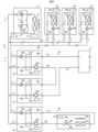
- FIG. 1 is a circuit diagram of an air conditioner according to Embodiment 1.
- the air conditioner 100 of Embodiment 1 air-conditions a plurality of air-conditioned spaces in a building such as a building.
- the air conditioner 100 includes an outdoor unit 1, a plurality of refrigerant indoor units 2a to 2c, a heat medium indoor unit 3a, and a repeater connected between the outdoor unit 1 and the heat medium indoor unit 3a.
- the repeaters 4a and 4b perform heat exchange between the refrigerant supplied from the outdoor unit 1 and the heat medium.
- the repeaters 4a and 4b correspond to the "first repeater" and the "second repeater” of the present disclosure, respectively.
- the heat medium indoor unit 3a corresponds to the "first heat medium indoor unit” of the present disclosure.
- the outdoor unit 1 and the refrigerant indoor units 2a to 2c, and the outdoor unit 1 and the relay unit 4 are connected by refrigerant pipes 65 and 66 through which the refrigerant flows.
- the refrigerant indoor units 2a to 2c and the repeater 4 are connected in parallel to the outdoor unit 1.
- FIG. Further, the repeater 4a and the heat medium indoor unit 3a are connected by heat medium pipes 71a and 72a through which the heat medium flows.
- the repeater 4b and the hot water storage tank 6 are connected by heat medium pipes 73 and 74 through which the heat medium flows.
- the heat generated in the outdoor unit 1 is transferred to the refrigerant indoor units 2a to 2c and the repeaters 4a and 4b by the refrigerant flowing through the refrigerant pipes 65 and 66.
- the heat exchanged by the repeater 4a is transferred to the heat medium indoor unit 3a by the heat medium flowing through the heat medium pipe 71a.
- the refrigerant indoor units 2a to 2c of the air conditioner 100 directly cool or heat the air-conditioned space with the refrigerant supplied from the outdoor unit 1.
- the heat medium indoor unit 3a cools or heats the air-conditioned space with a heat medium to which heat is transferred from the refrigerant supplied from the outdoor unit 1.
- the air conditioner 100 includes both a refrigerant indoor unit that directly uses the refrigerant supplied from the outdoor unit 1 and a heat medium indoor unit that indirectly uses the refrigerant.
- the hot water storage tank 6 stores the heat medium heated by the refrigerant supplied from the outdoor unit 1 .
- the hot water storage tank 6 includes a pipe for supplying the heat medium before heating from the outside of the air conditioner 100 to the hot water storage tank 6, and a pipe for supplying the heated heat medium from the hot water storage tank 6 to the utilization side.
- a pipe is attached to supply the
- the refrigerant used in the air conditioner 100 is, for example, a single refrigerant such as R32, a pseudo-azeotropic mixed refrigerant such as R410A, or a refrigerant containing a double bond or CF 3 I in the chemical formula. refrigerants or mixtures thereof, natural refrigerants such as CF 3 I, CO 2 or propane.
- the heat medium used in the heat medium indoor unit 3a is, for example, water, brine (antifreeze), a mixture of brine and water, or a mixture of water and an additive having a high anticorrosion effect.
- the heat medium stored in the hot water storage tank 6 is, for example, water.
- the "heat medium" in the present disclosure is a heat medium other than a refrigerant and is non-toxic and non-flammable.
- the outdoor unit 1 includes a compressor 11, a channel switching valve 12, an outdoor heat exchanger 13, an outdoor fan 14, an accumulator 15, an outdoor refrigerant pipe 16, and an outdoor control device 17.
- the compressor 11 sucks a low-temperature, low-pressure gas refrigerant, compresses it, and discharges a high-temperature, high-pressure gas refrigerant.
- the compressor 11 is, for example, an inverter type compressor whose capacity is controllable. Compressor 11 is equivalent to the "1st compressor" of this indication.
- the channel switching valve 12 is, for example, a four-way valve.
- the flow path switching valve 12 switches the flow path of the refrigerant discharged from the compressor 11 according to the operation of the refrigerant indoor units 2a to 2c and the heat medium indoor unit 3a.
- the flow path switching valve 12 switches to the flow path indicated by the solid line in FIG. 1 during the heating operation, and switches to the flow path indicated by the broken line in FIG. 1 during the cooling operation.
- the channel switching valve 12 may be a combination of a three-way valve and a two-way valve.
- the outdoor heat exchanger 13 is, for example, a fin-tube heat exchanger.
- the outdoor heat exchanger 13 exchanges heat between the air supplied by the outdoor fan 14 and the refrigerant.
- the outdoor heat exchanger 13 functions as a condenser during cooling operation, and condenses and liquefies the refrigerant.
- the outdoor heat exchanger 13 functions as an evaporator during heating operation, and evaporates and gasifies the refrigerant.
- the outdoor fan 14 is, for example, a propeller fan.
- the outdoor fan 14 supplies air around the outdoor unit 1 to the outdoor heat exchanger 13 .
- the accumulator 15 is provided on the suction side of the compressor 11 and has a function of separating liquid refrigerant and gas refrigerant and a function of storing excess refrigerant.
- the outdoor refrigerant pipe 16 is a pipe inside the housing (not shown) of the outdoor unit 1 among the pipes through which the refrigerant of the air conditioner 100 flows.
- the outdoor refrigerant pipe 16 connects the outdoor heat exchanger 13, the accumulator 15, the compressor 11, and the flow path switching valve 12 in this order.
- the end portion of the outdoor refrigerant pipe 16 on the flow path switching valve 12 side is connected to the refrigerant pipe 65 .
- the outdoor heat exchanger 13 side end of the outdoor refrigerant pipe 16 is connected to the refrigerant pipe 66 .
- the outdoor control device 17 controls the operations of the compressor 11, the flow path switching valve 12, and the outdoor fan 14.
- the outdoor control device 17 is composed of a processing device having a memory for storing data and programs necessary for control and a CPU for executing the program, dedicated hardware such as ASIC or FPGA, or both.
- the outdoor control device 17 drives the compressor 11 based on the detection results of a pressure sensor (not shown) that detects the refrigerant pressure and a temperature sensor (not shown) that detects the refrigerant temperature or the outside air temperature mounted on the outdoor unit 1.
- the frequency, the flow path of the flow path switching valve 12, and the rotational speed of the outdoor fan 14 are controlled.
- the outdoor control device 17 includes indoor control devices 25a to 25c mounted on the refrigerant indoor units 2a to 2c, an indoor control device 35a mounted on the heat medium indoor unit 3a, and a relay control device mounted on the repeaters 4a and 4b. Data communication can occur between 46a and 46b.
- the refrigerant indoor units 2a to 2c supply the heat generated by the outdoor unit 1 to the cooling load or heating load of the air-conditioned space.
- the refrigerant indoor unit 2a includes a refrigerant heat exchanger 21a, an expansion valve 22a, an indoor fan 23a, an indoor refrigerant pipe 24a, and an indoor controller 25a.
- the refrigerant heat exchanger 21a is, for example, a fin-tube heat exchanger.
- the refrigerant heat exchanger 21a exchanges heat between the refrigerant and the air supplied by the indoor fan 23a.
- the refrigerant heat exchanger 21a functions as a condenser during heating operation, and condenses and liquefies the refrigerant. Further, the refrigerant heat exchanger 21a functions as an evaporator during cooling operation, and evaporates the refrigerant to gasify it.
- the expansion valve 22a is an electronic expansion valve whose opening degree is variably controlled.
- the expansion valve 22a is connected in series with the refrigerant heat exchanger 21a, and decompresses and expands the refrigerant flowing out of the refrigerant heat exchanger 21a or flowing into the refrigerant heat exchanger 21a.
- the indoor fan 23a is, for example, a cross-flow fan.
- the indoor fan 23a supplies air in the air-conditioned space to the refrigerant heat exchanger 21a.
- the condensing ability or evaporation ability of the refrigerant heat exchanger 21a is controlled by controlling the rotational speed of the indoor fan 23a by the indoor controller 25a.
- the indoor refrigerant pipe 24a is a pipe inside the housing (not shown) of the refrigerant indoor unit 2a among the pipes through which the refrigerant of the air conditioner 100 flows.
- the indoor refrigerant pipe 24a connects the refrigerant heat exchanger 21a and the expansion valve 22a.
- An end of the indoor refrigerant pipe 24 a on the refrigerant heat exchanger 21 a side is connected to the refrigerant pipe 65 .
- the end of the indoor refrigerant pipe 24 a on the expansion valve 22 a side is connected to the refrigerant pipe 66 .
- the indoor controller 25a controls the operation of the expansion valve 22a and the indoor fan 23a.
- the indoor control device 25a is composed of a processing device having a memory for storing data and programs necessary for control and a CPU for executing the program, dedicated hardware such as ASIC or FPGA, or both.
- the indoor controller 25a operates the expansion valve based on the detection results of a temperature sensor (not shown) that detects the temperature of the air-conditioned space and a temperature sensor (not shown) that detects the temperature of the refrigerant at the outlet and inlet of the refrigerant indoor unit 2a. 22a and the rotational speed of the indoor fan 23a are controlled.
- a temperature sensor is, for example, a thermistor.
- the indoor controller 25a controls the opening degree of the expansion valve 22a and the rotational speed of the indoor fan 23a, for example, according to the difference between the temperature of the air-conditioned space and the target temperature.
- the refrigerant indoor units 2b and 2c have the same configuration as the refrigerant indoor unit 2a. That is, the refrigerant indoor unit 2b includes a refrigerant heat exchanger 21b, an expansion valve 22b, an indoor fan 23b, an indoor refrigerant pipe 24b, and an indoor controller 25b. Similarly, the refrigerant indoor unit 2c includes a refrigerant heat exchanger 21c, an expansion valve 22c, an indoor fan 23c, an indoor refrigerant pipe 24c, and an indoor controller 25c. Since the configuration of each device of the refrigerant indoor units 2b and 2c is the same as that of the refrigerant indoor unit 2a, the explanation is omitted.
- the heat medium indoor unit 3a supplies the heat converted by the repeater 4a to the cooling load or heating load of the air-conditioned space.
- the heat medium indoor unit 3a includes a heat medium heat exchanger 31a, a flow control valve 32a, an indoor fan 33a, an indoor heat medium pipe 34a, and an indoor controller 35a.
- the heat medium heat exchanger 31a is, for example, a fin-tube heat exchanger.
- the heat medium heat exchanger 31a exchanges heat between the air supplied by the indoor fan 33a and the heat medium.
- the heat medium heat exchanger 31a corresponds to the "first heat medium heat exchanger" of the present disclosure.
- the flow control valve 32a is an electromagnetic valve whose opening degree is variably controlled.
- the flow control valve 32a is connected in series with the heat medium heat exchanger 31a and adjusts the flow rate of the heat medium flowing through the heat medium heat exchanger 31a.
- the indoor fan 33a is, for example, a cross-flow fan.
- the indoor fan 33a supplies air in the air-conditioned space to the heat medium heat exchanger 31a.
- the heating capacity or cooling capacity of the heat medium heat exchanger 31a is controlled by controlling the rotational speed of the indoor fan 33a by the indoor controller 35a.
- the indoor heat medium pipe 34a is a pipe that connects the heat medium heat exchanger 31a and the flow control valve 32a.
- the indoor heat medium pipe 34a is a pipe inside the housing (not shown) of the refrigerant indoor unit 2a among the pipes through which the heat medium of the air conditioner 100 flows.
- the end of the indoor heat medium pipe 34a on the heat medium heat exchanger 31 side is connected to the heat medium pipe 71a.
- the end on the side of the flow control valve 32a is connected to the heat medium pipe 72a.
- the indoor controller 35a controls the operation of the flow rate adjustment valve 32a and the indoor fan 33a.
- the indoor control device 35a is composed of a processing device having a memory for storing data and programs necessary for control and a CPU for executing the program, dedicated hardware such as ASIC or FPGA, or both.
- a temperature sensor (not shown) that detects the temperature of the air-conditioned space and a temperature sensor (not shown) that detects the temperature of the heat medium at the outlet and inlet of the heat medium indoor unit 3a, It controls the opening degree of the flow control valve 32a and the rotation speed of the indoor fan 33a.
- a temperature sensor is, for example, a thermistor.
- the indoor controller 35a controls the opening degree of the flow control valve 32a and the rotational speed of the indoor fan 33a, for example, according to the difference between the temperature of the air-conditioned space and the target temperature.
- the indoor control device 35a uses the detection result of a pressure sensor (not shown) attached to the front and rear of the flow control valve 32a and the Cv value corresponding to the opening degree of the flow control valve 32a stored in advance to determine the heat medium may be calculated, and the opening degree of the flow control valve 32a may be controlled based on the calculation result.
- the relay machine 4a includes a relay heat exchanger 41a, an expansion valve 42a, a pump 43a, a relay refrigerant pipe 44a, a relay heat medium pipe 45a, and a relay control device 46a.
- the relay heat exchanger 41a is, for example, a plate heat exchanger.
- the relay heat exchanger 41a has a refrigerant channel (not shown) through which the refrigerant supplied from the outdoor unit 1 flows, and a heat medium channel (not shown) through which the heat medium circulated by the pump 43a flows.
- the relay heat exchanger 41a exchanges heat between the refrigerant flowing through the refrigerant channel and the heat medium flowing through the heat medium channel.
- the relay heat exchanger 41a functions as a condenser during heating operation, and condenses and liquefies the refrigerant. Further, the relay heat exchanger 41a functions as an evaporator during cooling operation, and evaporates the refrigerant to gasify it.
- the expansion valve 42a is an electronic expansion valve whose opening degree is variably controlled.
- the expansion valve 42a is connected in series with the refrigerant flow path of the relay heat exchanger 41a, and decompresses and expands the refrigerant flowing out of the relay heat exchanger 41a or flowing into the relay heat exchanger 41a.
- the pump 43a is, for example, an inverter-type centrifugal pump whose capacity is controllable.
- the pump 43a has a motor driven by an inverter, and is driven using the motor as a power source to apply pressure to the heat medium flowing through the heat medium flow path of the relay heat medium pipe 45b.
- the pump 43a is arranged so that the flow of the refrigerant and the flow of the heat medium during the cooling operation are opposed to each other. They may be arranged for opposing heating counterflow.
- the pump 43a is provided inside the repeater 4a, and is not provided in the heat medium pipes 71a and 72a connecting the repeater 4a and the heat medium indoor unit 3a.
- the relay refrigerant pipe 44a is a pipe inside the housing (not shown) of the relay device 4a among the pipes through which the refrigerant of the air conditioner 100 flows.
- the relay refrigerant pipe 44a connects the refrigerant flow path of the relay heat exchanger 41a and the expansion valve 42a.
- the relay heat exchanger 41 a side end of the relay refrigerant pipe 44 a is connected to the refrigerant pipe 65 .
- the end of the relay refrigerant pipe 44 a on the expansion valve 42 a side is connected to the refrigerant pipe 66 .
- the relay heat medium pipe 45a is a pipe inside the housing of the repeater 4a among the pipes through which the heat medium of the air conditioner 100 flows.
- the relay heat medium pipe 45a connects the heat medium flow path of the relay heat exchanger 41a and the pump 43a.
- the end of the relay heat medium pipe 45a on the side of the relay heat exchanger 41a is connected to the heat medium pipe 71a.
- the pump 43a side end of the relay heat medium pipe 45a is connected to the heat medium pipe 72a.
- the relay control device 46a controls the operations of the expansion valve 42a and the pump 43a.
- the relay control device 46a is composed of a processing device having a memory for storing data and programs required for control and a CPU for executing the program, dedicated hardware such as ASIC or FPGA, or both.
- the relay control device 46a controls the opening degree of the expansion valve 42a based on the detection result of a temperature sensor (not shown) that detects the refrigerant temperature at the refrigerant-side outlet and inlet of the relay heat exchanger 41a.
- the relay control device 46a may control the opening degree of the expansion valve 42a according to the operating capacity of the heat medium indoor unit 3a.
- the relay control device 46a may perform data communication with the indoor control device 25a and control the expansion valves 42a in conjunction with the expansion valves 22a mounted on the refrigerant indoor units 2a to 2c.
- the relay control device 46a detects the pressure of the heat medium attached to the outlet and inlet of the pump 43a, and the pressure sensor (not shown) that detects the pressure of the heat medium. It controls the driving frequency of 43a.
- the relay control device 46a may control the drive frequency of the pump 43a according to the operating capacity of the heat medium indoor unit 3a.
- the repeater 4b has the same configuration as the repeater 4a. That is, the relay 4b includes a relay heat exchanger 41b, an expansion valve 42b, a pump 43b, a relay refrigerant pipe 44b, a relay heat medium pipe 45b, and a relay control device 46b. Since the configuration of each device of the repeater 4b is the same as that of the repeater 4a, the explanation is omitted.
- the pump 43b is provided inside the repeater 4b and is not provided in the heat medium pipe 73 or 74 connecting the repeater 4b and the hot water storage tank 6.
- the relay heat exchangers 41a and 41b respectively correspond to the "first relay heat exchanger” and the "second relay heat exchanger” of the present disclosure.
- the pumps 43a and 43b respectively correspond to the "first pump” and the "second pump” of the present disclosure.
- the repeater 4b is connected to the hot water storage tank 6 unlike the repeater 4a. That is, the end portion of the relay refrigerant pipe 44 b on the side of the relay heat exchanger 41 b is connected to the heat medium pipe 73 . Similarly, the pump 43 b side end of the relay refrigerant pipe 44 b is connected to the heat medium pipe 74 .
- the relay control device 46b controls the opening degree of the expansion valve 42b and the driving of the pump 43b so that the temperature of the heat medium supplied to the hot water storage tank 6 through the heat medium pipe 73 reaches the required temperature.
- the sensors include a temperature sensor (not shown) for detecting the refrigerant temperature at the refrigerant-side outlet and inlet of the relay heat exchanger 41b, and a heat-medium temperature at the heat-medium-side outlet and inlet of the relay heat exchanger 41b.
- a temperature sensor (not shown) or the like is used.
- the required temperature of the heat medium is, for example, set based on an instruction from a remote controller (not shown) or the like for the hot water storage tank 6, and is a temperature obtained from the outlet hot water temperature desired by the user. Further, when the air conditioner 100 performs cooling operation, the relay control device 46b fixes the opening degree of the expansion valve 42b to fully closed, and stops driving the pump 43b.
- the air conditioner 100 includes a refrigerant circuit 91 through which a refrigerant circulates, and heat medium circuits 93 and 94 through which a heat medium circulates.
- the refrigerant circuit 91 includes the compressor 11 of the outdoor unit 1, the flow path switching valve 12, the outdoor heat exchanger 13, and the accumulator 15, the refrigerant heat exchangers 21a to 21c of the refrigerant indoor units 2a to 2c, and the expansion valves 22a to 22c, the refrigerant passages of the relay heat exchangers 41a and 41b of the relays 4a and 4b, and the expansion valves 42a and 42b are connected to the outdoor refrigerant pipe 16, the indoor refrigerant pipes 24a to 24c, the relay refrigerant pipes 44a and 44b, and It is configured to be connected by refrigerant pipes 65 and 66 .
- the compressor 11 circulates the refrigerant within the refrigerant circuit 91 .
- the refrigerant circuit 91 corresponds to the "first refrigerant circuit" of the present disclosure, and the refrigerant flowing through the refrigerant circuit 91 corresponds to the "first refrigerant" of the present disclosure.
- the heat medium flow path and the pump 43a of the relay heat exchanger 41a of the repeater 4a and the heat medium heat exchanger 31a and the flow control valve 32a of the heat medium indoor unit 3a are connected by the heat medium pipes 71a and 72a. Connected and configured.
- the pump 43 a circulates the heat medium in the heat medium circuit 93 .
- the heat medium circuit 93 corresponds to the "first heat medium circuit" of the present disclosure.
- the heat medium circuit 94 is configured by connecting the heat medium side of the relay heat exchanger 41b of the repeater 4b, the pump 43b, and the hot water storage tank 6 with heat medium pipes 73 and 74.
- the pump 43 b circulates the heat medium in the heat medium circuit 94 .
- the heat medium circuit 94 corresponds to the "second heat medium circuit" of the present disclosure.
- the air conditioner 100 performs cooling operation or heating operation based on instructions from a remote controller (not shown) or the like for the refrigerant indoor units 2a to 2c and the heat medium indoor unit 3a. Cooling operation and heating operation are realized by switching the channel switching valve 12 of the outdoor unit 1 . Solid arrows in FIG. 2 indicate the flow of refrigerant during heating operation, and broken arrows indicate the flow of refrigerant during cooling operation. The refrigerant flow in each operation will be described below.
- the high-temperature and high-pressure gas refrigerant discharged from the compressor 11 flows out from the outdoor unit 1 through the flow path switching valve 12, and flows through the refrigerant pipe 65 to the refrigerant indoor units 2a to 2c and the relay machine. 4a and 4b.
- the refrigerant that has flowed into the refrigerant indoor units 2a to 2c exchanges heat with the air supplied by the indoor fans 23a to 23c in the refrigerant heat exchangers 21a to 21c, and is condensed and liquefied.
- the refrigerant dissipates heat to the air in the air-conditioned space, thereby heating the air-conditioned spaces in which the refrigerant indoor units 2a to 2c are installed.
- the refrigerant flowing out of the refrigerant heat exchangers 21a-21c is depressurized by the expansion valves 22a-22c, flows out of the refrigerant indoor units 2a-2c, and flows into the outdoor unit 1 through the refrigerant pipe 66.
- the refrigerant that has flowed into the relay 4a exchanges heat with the heat medium circulated by the pump 43a in the relay heat exchanger 41a, condenses, and liquefies. At this time, the refrigerant radiates heat to the heat medium, thereby heating the heat medium.
- the refrigerant flowing out of the relay heat exchanger 41a is decompressed by the expansion valve 42a, flows out of the relay machine 4a, joins the refrigerant flowing out of the refrigerant indoor units 2a to 2c in the refrigerant pipe 66, and flows into the outdoor unit 1.
- the refrigerant that has flowed into the relay 4b exchanges heat with the heat medium circulated by the pump 43b in the relay heat exchanger 41b, condenses, and liquefies. At this time, the refrigerant radiates heat to the heat medium, thereby heating the heat medium.
- the refrigerant flowing out of the relay heat exchanger 41b is decompressed by the expansion valve 42b, flows out of the relay machine 4b, joins the refrigerant flowing out of the refrigerant indoor units 2b to 2c in the refrigerant pipe 66, and flows into the outdoor unit 1.
- the refrigerant that has flowed into the outdoor unit 1 flows into the outdoor heat exchanger 13 .
- the refrigerant that has flowed into the outdoor heat exchanger 13 exchanges heat with the air supplied by the outdoor fan 14 to evaporate and gasify.
- the refrigerant that has flowed out of the outdoor heat exchanger 13 is sucked into the compressor 11 again via the flow path switching valve 12 and the accumulator 15 .
- the heat medium heated by the relay heat exchanger 41a flows into the heat medium indoor unit 3a through the heat medium pipe 71a.
- the heat medium that has flowed into the heat medium indoor unit 3a exchanges heat with the air supplied by the indoor fan 33a in the heat medium heat exchanger 31a.
- the heat medium radiates heat to the air in the air-conditioned space, thereby heating the air-conditioned space in which the heat medium indoor unit 3a is installed.
- the heat medium that has flowed out of the heat medium heat exchanger 31a passes through the flow control valve 32a, flows out of the heat medium indoor unit 3a, and flows through the heat medium pipe 6b into the repeater 4a.
- the heat medium heated by the relay heat exchanger 41b passes through the heat medium pipe 73 and is stored in the hot water storage tank 6 .
- the heat medium that has not been supplied to the user side flows through the heat medium pipe 74 into the repeater 4b.
- the heat medium supplied to the hot water tank 6 from the outside is heated by circulating through the heat medium circuit 94 and stored in the hot water tank 6 .
- the high-temperature and high-pressure gas refrigerant discharged from the compressor 11 passes through the flow path switching valve 12 and flows into the outdoor heat exchanger 13 .
- the refrigerant that has flowed into the outdoor heat exchanger 13 exchanges heat with the air supplied by the outdoor fan 14, condenses, and liquefies.
- Refrigerant flowing out of the outdoor heat exchanger 13 passes through the refrigerant pipe 66 and is split between the refrigerant indoor units 2a to 2c and the repeaters 4a and 4b.
- the refrigerant that has flowed into the refrigerant indoor units 2a to 2c is decompressed by the expansion valves 22a to 22c, becomes a low-temperature gas-liquid two-phase refrigerant, and flows into the refrigerant heat exchangers 21a to 21c.
- the refrigerant that has flowed into the refrigerant heat exchangers 21a-21c exchanges heat with the air supplied by the indoor fans 23a-23c, evaporates, and becomes gas.
- the air-conditioned spaces in which the refrigerant indoor units 2a to 2c are installed are cooled by the refrigerant absorbing heat from the air in the air-conditioned spaces.
- the refrigerant that has flowed out of the refrigerant heat exchanger 21 a flows into the outdoor unit 1 through the refrigerant pipe 65 .
- the refrigerant that has flowed into the relay 4a is decompressed by the expansion valve 42a, becomes a low-temperature gas-liquid two-phase refrigerant, and flows into the relay heat exchanger 41a.
- the refrigerant that has flowed into the relay heat exchanger 41a exchanges heat with the heat medium circulated by the pump 43a, evaporates, and gasifies. At this time, the heat medium is cooled by the refrigerant absorbing heat from the heat medium.
- the refrigerant flowing out of the relay heat exchanger 41a joins the refrigerant flowing out of the refrigerant indoor units 2a to 2c in the refrigerant pipe 65 and flows into the outdoor unit 1.
- the refrigerant that has flowed into the outdoor unit 1 is sucked into the compressor 11 again via the flow path switching valve 12 and the accumulator 15 .
- the heat medium cooled by the relay heat exchanger 41a flows into the heat medium indoor unit 3a through the heat medium pipe 6a.
- the heat medium that has flowed into the heat medium indoor unit 3a exchanges heat with the air supplied by the indoor fan 33a in the heat medium heat exchanger 31a.
- the heat medium absorbs heat from the air in the air-conditioned space, thereby cooling the air-conditioned space in which the heat medium indoor unit 3a is installed.
- the heat medium that has flowed out of the heat medium heat exchanger 31a passes through the flow control valve 32a, flows out of the heat medium indoor unit 3a, and flows through the heat medium pipe 6b into the repeater 4a.
- the opening degree of the expansion valve 42b is fixed to fully closed, and the driving of the pump 43b is stopped. Therefore, in the relay heat exchanger 41b of the relay device 4b during the cooling operation, substantially no heat exchange occurs between the refrigerant circulating in the refrigerant circuit 91 and the heat medium circulating in the heat medium circuit 94. not.
- the repeater 4b has the pump 43b. Therefore, there is no need to provide a pump for the heat medium pipes 73 and 74 connecting the relay 4b and the hot water storage tank 6.
- FIG. Therefore, according to the air conditioner 100 of Embodiment 1, it is possible to omit the installation of the pump at the time of construction of the hot water storage tank 6, thereby reducing the on-site work cost.
- the air conditioner 100 of Embodiment 1 includes not only the refrigerant indoor units 2a to 2c and the hot water storage tank 6, but also the heat medium indoor unit 3a as load-side devices. Therefore, the occurrence of energy loss in the air conditioner 100 as a whole is suppressed. Further, in the heat medium indoor unit 3a provided with the heat medium heat exchanger 31a, there is no need to prepare for refrigerant leakage in the room.
- the refrigerant charge amount can be reduced.
- the air conditioner 100 of Embodiment 1 it is possible to select the form of the indoor unit from the viewpoint of energy saving performance and necessity of safety measures.
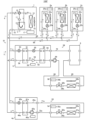
- FIG. 2 is a circuit diagram of the air conditioner 100A according to the second embodiment. As shown in FIG. 2, the second embodiment differs from the first embodiment in that an air conditioner 100A has a repeater 4c. In the second embodiment, the same reference numerals are assigned to the same parts as in the first embodiment, and the description thereof is omitted.
- the repeater 4c is connected in series with the repeater 4b and the hot water storage tank 6. Specifically, the repeater 4b and the hot water storage tank 6 are connected by a heat medium pipe 73 through which the heat medium flows. The hot water storage tank 6 and the repeater 4c are connected by a heat medium pipe 75 through which a heat medium flows. Furthermore, the repeater 4c and the repeater 4b are connected by a heat medium pipe 76 through which a heat medium flows.
- the repeater 4c has the same configuration as the repeaters 4a and 4b. That is, the relay machine 4c includes a relay heat exchanger 41c, an expansion valve 42c, a pump 43c, a relay refrigerant pipe 44c, a relay heat medium pipe 45c, and a relay control device 46c.
- the configuration of each device included in the repeater 4c is the same as that of each device of the repeaters 4a and 4b, so the description is omitted.
- the repeater 4c corresponds to the "third repeater” of the present disclosure.
- the relay heat exchanger 41c corresponds to the "third relay heat exchanger” of the present disclosure.
- the pump 43c corresponds to the "third pump” of the present disclosure.
- the relay heat medium pipes 45b and 45c of the repeaters 4b and 4c are connected to the heat medium pipes 73, 75 and 76 as follows. That is, the end of the relay heat medium pipe 45 b on the side of the relay heat exchanger 41 b is connected to the heat medium pipe 73 . Similarly, the pump 43 b side end of the relay heat medium pipe 45 b is connected to the heat medium pipe 76 . Also, the end of the relay heat medium pipe 45 c on the side of the relay heat exchanger 41 c is connected to the heat medium pipe 76 . Similarly, the pump 43 c side end of the relay heat medium pipe 45 c is connected to the heat medium pipe 75 .
- the relay control device 46c controls the opening degree of the expansion valve 42c and the driving of the pump 43c so that the temperature of the heat medium supplied to the hot water storage tank 6 through the heat medium pipe 73 reaches the required temperature.
- the sensors include a temperature sensor (not shown) that detects the refrigerant temperature at the refrigerant-side outlet and inlet of the relay heat exchanger 41c, and a heat-medium temperature at the heat-medium-side outlet and inlet of the relay heat exchanger 41c.
- a temperature sensor (not shown) or the like is used.
- relay control devices 46b and 46c perform data communication with each other and perform control to interlock the expansion valves 42b and 42c and the pumps 43b and 43c. Specifically, when the load is light, that is, when the required temperature for the hot water storage tank 6 is low, only one of the pumps 43b and 43c is driven. On the other hand, when the load is large, that is, when the required temperature for the hot water storage tank 6 is high, both the pumps 43b and 43c are driven at 100% output, for example.
- expansion is performed so as to reduce this difference. It adjusts the opening of the valves 42b and 42c and the distribution of the outputs of the pumps 43b and 43c.
- inlet/outlet temperature differences ⁇ Tr_b and ⁇ Tr_c are the detection results of the temperature sensors that detect the refrigerant temperature at the refrigerant-side outlets of the relay heat exchangers 41b and 41c and the detection results of the temperature sensors that detect the refrigerant temperature at the refrigerant-side inlets. equivalent to the difference between
- the refrigerant circuit 91 in Embodiment 2 includes the compressor 11, the flow path switching valve 12, the outdoor heat exchanger 13, and the accumulator 15 of the outdoor unit 1, and the refrigerant heat exchangers of the refrigerant indoor units 2a to 2c.
- 21a to 21c, the expansion valves 22a to 22c, the refrigerant passages of the relay heat exchangers 41a to 41c of the relay machines 4a to 4c, and the expansion valves 42a to 42c are connected to the outdoor refrigerant pipe 16 and the indoor refrigerant pipes 24a to 24c.
- relay refrigerant pipes 44 a to 44 c and refrigerant pipes 65 and 66 .
- the heat medium circuit 94 of the second embodiment includes the heat medium flow path of the relay heat exchanger 41b of the repeater 4b and the pump 43b, and the heat medium flow path of the relay heat exchanger 41c of the repeater 4c and the pump 43c.
- the hot water storage tank 6 are connected by a relay heat medium pipe 45 b , a relay heat medium 45 c , and heat medium pipes 73 , 75 and 76 .
- Pumps 43 b and 43 c circulate the heat medium in heat medium circuit 94 .
- the heat medium circuit 94 of the second embodiment also corresponds to the "second heat medium circuit" of the present disclosure.
- the refrigerant flow during heating operation will be described below, focusing on the differences from the first embodiment.
- the high-temperature and high-pressure gas refrigerant discharged from the compressor 11 flows out from the outdoor unit 1 through the flow path switching valve 12, and flows through the refrigerant pipe 65 to the refrigerant indoor units 2a to 2c and the relay machine. 4a to 4c.
- the refrigerant that has flowed into the relay 4c exchanges heat with the heat medium circulated by the pump 43c in the relay heat exchanger 41c, condenses, and liquefies. At this time, the refrigerant radiates heat to the heat medium, thereby heating the heat medium.
- the refrigerant flowing out of the relay heat exchanger 41c is decompressed by the expansion valve 42c, flows out of the relay 4c, joins the refrigerant flowing out of the refrigerant indoor units 2c to 2c in the refrigerant pipe 66, and flows into the outdoor unit 1.
- the heat medium heated by the relay heat exchanger 41c passes through the heat medium pipe 76 and is further heated by the relay heat exchanger 41b.
- the heat medium heated by the relay heat exchanger 41 b passes through the heat medium pipe 73 and is stored in the hot water storage tank 6 .
- the heat medium stored in the hot water storage tank 6 the heat medium that has not been supplied to the user side passes through the heat medium pipe 75 and flows into the relay heat exchanger 41c.
- the heat medium supplied to the hot water tank 6 from the outside is heated by circulating through the heat medium circuit 94 and stored in the hot water tank 6 .
- the repeaters 4b and 4c have the pumps 43b and 43c. Therefore, it is not necessary to provide the heat medium pipes 73, 75 and 76 with pumps. Therefore, according to the air conditioner 100A of Embodiment 2, it is possible to omit the installation of the pump at the time of construction of the hot water storage tank 6, thereby reducing the on-site work cost.
- the air conditioner 100A of Embodiment 2 has not only the refrigerant indoor units 2a to 2c and the hot water storage tank 6, but also the heat medium indoor unit 3a as load-side devices. Therefore, the occurrence of energy loss in the entire air conditioner 100A is suppressed. Further, in the heat medium indoor unit 3a provided with the heat medium heat exchanger 31a, there is no need to prepare for refrigerant leakage in the room. Furthermore, compared to air conditioners having only refrigerant indoor units, the refrigerant charge amount can be reduced. As described above, in the air conditioner 100A of Embodiment 2, the form of the indoor unit can be selected from the viewpoint of energy saving performance and necessity of safety measures.
- the heat medium circuit 94 of the air conditioner 100A of Embodiment 2 includes two relay heat exchangers 41b and 41c connected in series. Therefore, it is possible to store a heat medium having a higher temperature than that in the first embodiment in the hot water storage tank 6 and supply it to the user side.
- Embodiment 3. 3 is a circuit diagram of an air conditioner according to Embodiment 3.
- FIG. 3 the third embodiment differs from the second embodiment in that it includes a heat medium indoor unit 3b.
- the same reference numerals are given to the same parts as in the second embodiment, and the description thereof is omitted.
- the heat medium indoor unit 3b is connected in series with the repeaters 4b and 4c and the hot water storage tank 6. Specifically, the repeater 4b and the hot water storage tank 6 are connected by a heat medium pipe 73 through which the heat medium flows. The hot water storage tank 6 and the heat medium indoor unit 3b are connected by a heat medium pipe 77 through which the heat medium flows. Furthermore, the heat medium indoor unit 3b and the repeater 4c are connected by a heat medium pipe 78 through which the heat medium flows. The repeater 4c and the repeater 4b are connected by a heat medium pipe 76 through which a heat medium flows.
- the heat medium indoor unit 3b has the same configuration as the heat medium indoor unit 3a. That is, the heat medium indoor unit 3b includes a heat medium heat exchanger 31b, a flow control valve 32b, an indoor fan 33b, an indoor heat medium pipe 34b, and an indoor controller 35b. Since the configuration of each device of the heat medium indoor unit 3b is the same as that of the heat medium indoor unit 3a, the explanation is omitted.
- the heat medium indoor unit 3b corresponds to the "second heat medium indoor unit” of the present disclosure.
- the heat medium heat exchanger 31b corresponds to the "second heat medium heat exchanger" of the present disclosure.
- the relay heat medium pipes 45b and 45c of the repeaters 4b and 4c and the indoor heat medium pipe 34b of the heat medium indoor unit 3b are connected to heat medium pipes 73, 76, 77 and 78 as follows. That is, the end of the relay heat medium pipe 45 b on the side of the relay heat exchanger 41 b is connected to the heat medium pipe 73 . Similarly, the pump 43 b side end of the relay heat medium pipe 45 b is connected to the heat medium pipe 76 . Also, the end of the relay heat medium pipe 45 c on the side of the relay heat exchanger 41 c is connected to the heat medium pipe 76 . Similarly, the pump 43 c side end of the relay heat medium pipe 45 c is connected to the heat medium pipe 78 .
- the end portion of the indoor heat medium pipe 34 b on the side of the heat medium heat exchanger 31 b is connected to the heat medium pipe 77 .
- the end of the indoor heat medium pipe 34b on the side of the flow control valve 32b is connected to the heat medium pipe 78. As shown in FIG.
- the heat medium circuit 94 in the third embodiment includes the heat medium flow path and the pump 43b of the relay heat exchanger 41b of the repeater 4b, and the heat medium flow path and the pump of the relay heat exchanger 41c of the repeater 4c.
- 43c, the hot water storage tank 6, the heat medium heat exchanger 31b of the heat medium indoor unit 3b, and the flow control valve 32b are connected to the relay heat medium pipe 45b, the relay heat medium pipe 45c, the indoor heat medium pipe 34b, and the heat medium pipe 73. , 75 and 76.
- Pumps 43 b and 43 c circulate the heat medium in heat medium circuit 94 .
- the heat medium circuit 94 of Embodiment 3 also corresponds to the "second heat medium circuit" of the present disclosure.
- the relay control device 46c of the relay unit 4c determines the required temperature of the heat medium based on, for example, an instruction from a remote control or the like for the hot water storage tank 6 and an instruction from a remote control (not shown) for the heat medium indoor unit 3b. may be set.
- the heat medium circulated by the pumps 43b and 43c is heated in the relay heat exchanger 41c and then passed through the heat medium pipe 76 and further heated in the relay heat exchanger 41b.
- the heat medium heated by the relay heat exchanger 41 b passes through the heat medium pipe 73 and is stored in the hot water storage tank 6 .
- the heat medium that has not been supplied to the user side passes through the heat medium pipe 77 and flows into the heat medium indoor unit 3b.
- the heat medium that has flowed into the heat medium indoor unit 3b exchanges heat with the air supplied by the indoor fan 33b in the heat medium heat exchanger 31b. At this time, the heat medium radiates heat to the air in the air-conditioned space, thereby heating the air-conditioned space in which the heat medium indoor unit 3b is installed.
- the heat medium that has flowed out of the heat medium heat exchanger 31b passes through the flow control valve 32b, flows out of the heat medium indoor unit 3b, passes through the heat medium pipe 78, and flows into the repeater 4c. In this manner, the heat medium supplied to the hot water tank 6 from the outside is heated by circulating through the heat medium circuit 94 and stored in the hot water tank 6 . Further, the heat medium stored in the hot water storage tank 6 is primarily used in the hot water storage tank 6 and is secondarily used in the heat medium indoor unit 3b.
- the repeaters 4b and 4c have the pumps 43b and 43c. Therefore, there is no need to provide pumps for the heat medium pipes 73 and 76-78. Therefore, according to the air conditioner 100B of Embodiment 3, it is possible to omit the installation of the pump at the time of construction of the hot water storage tank 6, thereby reducing the on-site work cost.
- the air conditioner 100B of Embodiment 3 has not only the refrigerant indoor units 2a to 2c and the hot water storage tank 6, but also the heat medium indoor units 3a and 3b as load-side devices. Therefore, the occurrence of energy loss in the entire air conditioner 100B is suppressed. Moreover, in the heat medium indoor units 3a and 3b provided with the heat medium heat exchanger 31a, there is no need to prepare for refrigerant leakage indoors. Furthermore, compared to air conditioners having only refrigerant indoor units, the refrigerant charge amount can be reduced. As described above, in the air conditioner 100B of Embodiment 3, the form of the indoor unit can be selected from the viewpoint of the energy saving performance and necessity of safety measures.
- the heat medium circuit 94 of the air conditioner 100B of Embodiment 3 includes two relay heat exchangers 41b and 41c connected in series. Therefore, it is possible to store a heat medium having a higher temperature than that in the first embodiment in the hot water storage tank 6 and supply it to the user side.
- the heat medium circuit 94 of the air conditioner of Embodiment 3 includes the hot water storage tank 6 and the heat medium heat exchanger 31b of the heat medium indoor unit 3b. Therefore, by circulating the heat medium circuit 94, the heated heat medium can be used secondary in the heat medium indoor unit 3b, and the air conditioner 100B can be efficiently operated.
- FIG. 4 is a circuit diagram of an air conditioner 100C according to Embodiment 4. As shown in FIG. As shown in FIG. 4, the fourth embodiment differs from the first embodiment in that a heat medium heater 5 is provided. In the fourth embodiment, the same reference numerals are assigned to the same parts as in the first embodiment, and the description thereof is omitted.
- the outdoor unit 1 and the heat medium heater 5 are connected by refrigerant pipes 65 and 66 through which refrigerant flows.
- the heat medium heater 5 is connected to the outdoor unit 1 in parallel with the refrigerant indoor units 2a to 2c and the repeaters 4a and 4b.
- the heat medium heater 5 and the hot water storage tank 6 are connected by a heat medium pipe 79 through which the heat medium flows.
- the hot water storage tank 6 and the repeater 4b are connected by a heat medium pipe 80 through which a heat medium flows.
- the repeater 4b and the heat medium heater 5 are connected by a heat medium pipe 81 through which the heat medium flows.
- the heat medium heater 5 heats the heat medium to a high temperature using the refrigerant supplied from the outdoor unit 1 .
- the heat medium heater 5 includes an upper heat exchanger 51, a lower heat exchanger 52, an expansion valve 53, a compressor 54, an expansion valve 55, a temperature rising primary refrigerant pipe 56, a temperature rising secondary refrigerant pipe 57, and a temperature rising heat.
- a medium line 58 is provided.
- the upper heat exchanger 51 is, for example, a plate heat exchanger.
- the upper heat exchanger 51 includes a primary refrigerant passage (not shown) through which refrigerant supplied from the outdoor unit 1 and circulated in the refrigerant circuit 91 flows, and a refrigerant circuit 92 (described later) through which the refrigerant flows through the compressor 54 . It has a secondary coolant channel (not shown).
- the upper heat exchanger 51 exchanges heat between the refrigerant flowing through the primary refrigerant flow path and the heat medium flowing through the secondary refrigerant flow path. Thereby, the heat stored in the refrigerant flowing through the refrigerant circuit 91 is transferred to the refrigerant flowing through the refrigerant circuit 92 .
- the upper heat exchanger 51 functions as an evaporator that evaporates and gasifies the refrigerant flowing through the refrigerant circuit 92 .
- the lower heat exchanger 52 is, for example, a plate heat exchanger.
- the lower heat exchanger 52 includes a refrigerant flow path (not shown) through which the refrigerant circulating in the refrigerant circuit 92 by the compressor 54 flows, and a heat medium flow path (not shown) through which the heat medium circulates in the heat medium circuit 94 by the pump 43b. ).
- the lower heat exchanger 52 exchanges heat between the refrigerant flowing through the refrigerant flow path and the heat medium flowing through the heat medium flow path. Thereby, the heat stored in the refrigerant flowing through the refrigerant circuit 92 is transferred to the heat medium flowing through the heat medium circuit 94 .
- the lower heat exchanger 52 functions as a condenser that condenses and liquefies the refrigerant flowing through the refrigerant circuit 92 .
- the expansion valve 53 is an electronic expansion valve whose opening degree is variably controlled.
- the expansion valve 53 is connected in series with the primary refrigerant flow path of the upper heat exchanger 51 and decompresses and expands the refrigerant flowing out of the upper heat exchanger 51 or flowing into the upper heat exchanger 51 .
- the compressor 54 sucks in low-temperature and low-pressure gas refrigerant, compresses it, and discharges high-temperature and high-pressure gas refrigerant.
- the compressor 54 is connected in series between the upper heat exchanger 51 and the lower heat exchanger 52 .
- the compressor 54 is, for example, an inverter type compressor whose capacity is controllable. Note that the compressor 54 corresponds to the "second compressor" of the present disclosure.
- the expansion valve 55 is an electronic expansion valve whose opening is variably controlled.
- the expansion valve 55 is connected between the lower heat exchanger 52 and the upper heat exchanger 51 and reduces the pressure of the refrigerant flowing out of the lower heat exchanger 52 and flowing into the upper heat exchanger 51 to expand the refrigerant.
- the temperature rising primary refrigerant pipe 56 is a pipe inside the housing (not shown) of the heat medium heater 5 among the pipes through which the refrigerant of the air conditioner 100C flows.
- the temperature rising primary refrigerant pipe 56 connects the refrigerant flow path of the upper heat exchanger 51 and the expansion valve 53 .
- An end portion of the temperature rising primary refrigerant pipe 56 on the upper heat exchanger 51 side is connected to the refrigerant pipe 65 .
- the end of the temperature rising primary refrigerant pipe 56 on the expansion valve 53 side is connected to the refrigerant pipe 66 .
- the temperature rising secondary refrigerant pipe 57 is a pipe independent from the temperature rising primary refrigerant pipe 56 inside the housing of the heat medium heater 5 among the pipes through which the refrigerant of the air conditioner 100C flows.
- the temperature rising secondary refrigerant pipe 57 annularly connects the secondary refrigerant flow path of the upper heat exchanger 51, the expansion valve 55, the refrigerant flow path of the lower heat exchanger 52, and the compressor 54 in this order. .
- the heating heat medium pipe 58 is a pipe inside the housing of the heat medium heater 5 among the pipes through which the heat medium of the air conditioner 100C flows.
- the end of the temperature-increasing heat medium pipe 58 on the outlet side of the heat medium flow path in the lower heat exchanger 52 is connected to the heat medium pipe 79 .
- the end of the heating medium pipe 58 on the inlet side of the heat medium flow path in the lower heat exchanger 52 is connected to the heat medium pipe 81 .
- a temperature increase control device 59 controls the operations of the expansion valve 53 , the compressor 54 and the expansion valve 55 .
- the temperature increase control device 59 is composed of a processing device having a memory for storing data and programs necessary for control and a CPU for executing the programs, dedicated hardware such as ASIC or FPGA, or both.
- the temperature rise control device 59 and the relay control device 46b perform data communication with each other, and based on the detection result of each sensor, the temperature of the heat medium supplied to the hot water storage tank 6 through the heat medium pipe 73 is adjusted to the required temperature.
- the opening degrees of the expansion valves 42b, 53 and 55 and the drive frequency of the pump 43b and the compressor 54 are controlled.
- the sensors include a temperature sensor (not shown) that detects the refrigerant temperature at the outlet or inlet of the primary refrigerant flow path of the upper heat exchanger 51, and a temperature sensor that detects the refrigerant temperature on the upstream and downstream sides of the compressor 54.
- a sensor (not shown) and a temperature sensor (not shown) for detecting the temperature of the heat medium at the outlet and inlet of the heat medium flow path of the lower heat exchanger 52 are used.
- Temperature sensors (not shown) for detecting the refrigerant temperature at the refrigerant-side outlet and inlet of the relay heat exchanger 41b, and temperature sensors for detecting the heat-medium temperature at the heat-medium-side outlet and inlet of the relay heat exchanger 41b. (not shown) may be used.
- the relay control device 46b fixes the opening degree of the expansion valve 42b to fully closed when the air conditioner 100C performs the cooling operation.
- the refrigerant circuit 91 of the fourth embodiment includes the compressor 11 of the outdoor unit 1, the flow path switching valve 12, the outdoor heat exchanger 13, and the accumulator 15, the refrigerant heat exchangers 21a to 21c of the refrigerant indoor units 2a to 2c, and the expansion valves 22a to 22c, the refrigerant flow paths of the relay heat exchangers 41a and 41b of the relays 4a and 4b, the expansion valves 42a and 42b, and the primary refrigerant flow of the upper stage heat exchanger 51 of the heat medium heater 5 and the expansion valve 53 are connected by the outdoor refrigerant pipe 16, the indoor refrigerant pipes 24a to 24c, the relay refrigerant pipes 44a and 44b, the temperature rising primary refrigerant pipes, and the refrigerant pipes 65 and 66.
- the compressor 11 circulates the refrigerant within the refrigerant circuit 91 .
- the refrigerant circuit 91 of Embodiment 4 also corresponds to the "first refrigerant circuit" of the present disclosure, and the refrigerant flowing through the refrigerant circuit 91 corresponds to the "first refrigerant" of the present disclosure.
- the compressor 54, the secondary refrigerant flow path of the upper heat exchanger 51, the expansion valve 55, and the refrigerant flow path of the lower heat exchanger 52 are temperature rising secondary refrigerant pipes. 57.
- Compressor 54 circulates the refrigerant in refrigerant circuit 92 .
- the refrigerant circuit 92 of Embodiment 4 corresponds to the "second refrigerant circuit" of the present disclosure, and the refrigerant flowing through the refrigerant circuit 92 corresponds to the "second refrigerant" of the present disclosure.
- the refrigerant circulating in the refrigerant circuit 92 has a condensation temperature different from that of the refrigerant circulating in the refrigerant circuit 91 and has a lower pressure band than the refrigerant circulating in the refrigerant circuit 91, such as R134a, R-1234yf, or R-1234ze. is used.
- the heat medium circuit 94 of the fourth embodiment includes the heat medium flow path of the relay heat exchanger 41b of the repeater 4b and the pump 43b, the heat medium flow path of the lower heat exchanger 52 of the heat medium heater 5, and the hot water storage.
- the tank 6 is connected by a relay heat medium pipe 45b, a temperature raising heat medium pipe 58, and heat medium pipes 79-81.
- the pump 43 b circulates the heat medium in the heat medium circuit 94 .
- the heat medium circuit 94 of Embodiment 4 also corresponds to the "second heat medium circuit" of the present disclosure.
- FIG. 5 is a diagram showing the operating points of the refrigerant circuits 91 and 92 according to the fourth embodiment on a Ph diagram. The operation of the heat medium heater 5 will be described with reference to FIG.
- the solid line indicates the operating point of the refrigerant circuit 92 and the dashed line indicates the operating point of the refrigerant circuit 91 .
- 5 is the condensation temperature of the refrigerant circuit 91
- Te is the evaporation temperature of the refrigerant circuit 92. As shown in FIG.
- the refrigerant circuit 92 uses the heat of condensation of the refrigerant circulating in the refrigerant circuit 91 in the upper heat exchanger 51 to evaporate the refrigerant flowing through the refrigerant circuit 92 . Therefore, the evaporation temperature Te of the refrigerant circuit 92 increases. In the refrigerant circuit 92, the higher the evaporation temperature Te of the refrigerant circuit 92, the higher the condensation temperature Tc of the refrigerant circuit 92. Therefore, as shown in FIG. 5, the supercritical pressure is balanced. In the supercritical state, since latent heat does not change like in a normal refrigeration cycle, when the refrigerant flows through the lower heat exchanger 52, the refrigerant temperature undergoes a sensible heat change. Thus, the heat medium heater 5 can heat the heat medium to a high temperature.
- the refrigerant circulating in the refrigerant circuit 92 uses a refrigerant with a low pressure band such as R134a, R-1234yf, or R-1234ze. This eliminates the problem of withstand voltage and reduces the cost of the product. Note that the refrigerant circulating in the refrigerant circuit 92 is not limited to these.
- the refrigerant flow during heating operation will be described below, focusing on the differences from the first embodiment.
- the high-temperature and high-pressure gas refrigerant discharged from the compressor 11 flows out from the outdoor unit 1 through the flow path switching valve 12, and flows through the refrigerant pipe 65 to the refrigerant indoor units 2a to 2c and the relay machine. 4 a and 4 b and the heat medium heater 5 .
- the refrigerant that has flowed into the relay 4b exchanges heat with the heat medium circulated by the pump 43b in the relay heat exchanger 41b, condenses, and liquefies. At this time, the refrigerant radiates heat to the heat medium, thereby heating the heat medium.
- the refrigerant flowing out of the relay heat exchanger 41b is decompressed by the expansion valve 42b, flows out of the relay machine 4b, joins the refrigerant flowing out of the refrigerant indoor units 2b to 2c in the refrigerant pipe 66, and flows into the outdoor unit 1.
- the refrigerant that has flowed into the heat medium heater 5 exchanges heat with the refrigerant flowing through the secondary refrigerant flow path in the primary refrigerant flow path of the upper heat exchanger 51, condenses, and liquefies.
- the refrigerant circulating in the refrigerant circuit 91 radiates heat to the refrigerant circulating in the refrigerant circuit 92 , thereby heating the refrigerant circulating in the refrigerant circuit 92 .
- the refrigerant flowing out from the primary refrigerant flow path of the upper heat exchanger 51 is decompressed by the expansion valve 53, flows out from the heat medium heater 5, and joins the refrigerant flowing out from the refrigerant indoor units 2c to 2c in the refrigerant pipe 66. , flows into the outdoor unit 1 .
- the heat medium heated in the secondary refrigerant passage of the upper heat exchanger 51 is sucked into the compressor 54 .
- Refrigerant sucked into the compressor 54 is discharged in a state of high temperature and high pressure.
- the high-temperature and high-pressure gas refrigerant discharged from the compressor 54 exchanges heat with the heat medium circulating in the heat medium circuit 94 by the pump 43b in the refrigerant flow path of the lower heat exchanger 52, and is condensed and liquefied.
- the refrigerant in the second refrigerant circuit releases heat to the heat medium in the heat medium circuit 94, so that the heat medium in the heat medium circuit 94 is heated to a high temperature.
- the refrigerant flowing out of the lower heat exchanger 52 is depressurized by the expansion valve 55 and flows into the upper heat exchanger 51 .
- the heat medium heated by the relay heat exchanger 41b passes through the heat medium pipe 81 and is further heated to a high temperature by the lower heat exchanger 52 .
- the heat medium heated by the lower heat exchanger 52 passes through the heat medium 79 and is stored in the hot water storage tank 6 .
- the heat medium stored in the hot water storage tank 6 the heat medium that has not been supplied to the user side passes through the heat medium pipe 80 and flows into the relay heat exchanger 41b.
- the heat medium supplied to the hot water tank 6 from the outside is heated by circulating through the heat medium circuit 94 and stored in the hot water tank 6 .
- the opening degree of the expansion valve 42b is fixed to fully closed in the repeater 4b during the cooling operation. Therefore, in the relay heat exchanger 41b of the relay device 4b during the cooling operation, substantially no heat exchange occurs between the refrigerant circulating in the refrigerant circuit 91 and the heat medium circulating in the heat medium circuit 94. not. In other respects, the flow of the refrigerant flowing through the heat medium circuit 94 during the refrigerant operation is the same as during the heating operation, so the explanation is omitted.
- the repeater 4b has the pump 43b. Therefore, there is no need to provide a pump for the heat medium pipes 79-81. Therefore, according to the air conditioner 100C of Embodiment 4, it is possible to omit the installation of the pump at the time of construction of the hot water storage tank 6, and reduce the on-site work cost.
- the air conditioner 100C of Embodiment 4 has not only the refrigerant indoor units 2a to 2c and the hot water storage tank 6, but also the heat medium indoor unit 3a as load-side devices. Therefore, deterioration in performance of the entire air conditioner 100C is suppressed. Further, in the heat medium indoor unit 3a provided with the heat medium heat exchanger 31a, there is no need to prepare for refrigerant leakage in the room. Furthermore, compared to air conditioners having only refrigerant indoor units, the refrigerant charge amount can be reduced. As described above, in the air conditioner 100C of Embodiment 4, the form of the indoor unit can be selected from the viewpoint of the energy saving performance and necessity of safety measures.
- the heat medium circuit 94 of the air conditioner 100C of Embodiment 4 includes the relay heat exchanger 41b and the lower heat exchanger 52 of the heat medium heater 5, which are connected in series. Therefore, it is possible to store a heat medium having a higher temperature than that in the first embodiment in the hot water storage tank 6 and supply it to the user side.
- the air conditioner 100C of Embodiment 4 since the air conditioner 100C of Embodiment 4 has the heat medium heater 5, the heat medium having a higher temperature than when two relay heat exchangers are connected in series is stored in the hot water storage tank 6. It is possible to supply it to the user side.
- FIG. 6 is a circuit diagram of an air conditioner 100D according to Embodiment 5. As shown in FIG. As shown in FIG. 6, the fifth embodiment differs from the fourth embodiment in that a heat medium indoor unit 3b is provided. In the fifth embodiment, the same reference numerals are given to the same parts as in the fourth embodiment, and the description thereof is omitted, and the description will focus on the differences from the fourth embodiment.
- the heat medium indoor unit 3b is connected in series with the repeater 4b, the heat medium heater 5, and the hot water storage tank 6. Specifically, the heat medium heater 5 and the hot water storage tank 6 are connected by a heat medium pipe 79 through which the heat medium flows. The hot water storage tank 6 and the heat medium indoor unit 3b are connected by a heat medium pipe 82 through which the heat medium flows. Furthermore, the heat medium indoor unit 3b and the repeater 4b are connected by a heat medium pipe 83 through which the heat medium flows. The repeater 4b and the repeater 4b are connected by a heat medium pipe 81 through which a heat medium flows.
- the heat medium indoor unit 3b has the same configuration as the heat medium indoor unit 3a. That is, the heat medium indoor unit 3b includes a heat medium heat exchanger 31b, a flow control valve 32b, an indoor fan 33b, an indoor heat medium pipe 34b, and an indoor controller 35b.
- the configuration of each device included in the heat medium indoor unit 3b is also the same as that of the heat medium indoor unit 3a, so the explanation is omitted.
- the relay heat medium pipe 45b of the repeater 4b, the heating heat medium pipe 58 of the heat medium heater 5, and the indoor heat medium pipe 34b of the heat medium indoor unit 3b are arranged as follows. 83. That is, the end of the relay heat medium pipe 45 b on the side of the relay heat exchanger 41 b is connected to the heat medium pipe 81 . Similarly, the pump 43 b side end of the relay heat medium pipe 45 b is connected to the heat medium pipe 83 . The end of the heating medium pipe 58 on the outlet side of the heat medium flow path in the lower heat exchanger 52 is connected to the heat medium pipe 79 .
- the end of the heating medium pipe 58 on the inlet side of the heat medium flow path in the lower heat exchanger 52 is connected to the heat medium pipe 81 .
- the end portion of the indoor heat medium pipe 34 b on the heat medium heat exchanger 31 b side is connected to the heat medium pipe 82 .
- the end portion of the indoor heat medium pipe 34 b on the side of the flow control valve 32 b is connected to the heat medium pipe 83 .
- the heat medium circuit 94 in the fifth embodiment includes the heat medium flow path and the pump 43b of the relay heat exchanger 41b of the repeater 4b and the heat medium flow of the lower heat exchanger 52 of the heat medium heater 5.
- the path, the hot water storage tank 6, the heat medium heat exchanger 31b of the heat medium indoor unit 3b, and the flow control valve 32b are connected to the relay heat medium pipe 45b, the temperature increasing heat medium pipe 58, the indoor heat medium pipe 34b, and the heat medium pipe 79. , and 81-83.
- the pump 43 b circulates the heat medium in the heat medium circuit 94 .
- the heat medium circuit 94 of Embodiment 5 also corresponds to the "second heat medium circuit" of the present disclosure.
- the relay control device 46b and the temperature increase control device 59 use, for example, an instruction from a remote control for the hot water storage tank 6 and an instruction from a remote control (not shown) for the heat medium indoor unit 3b as the required temperature of the heat medium. You may make it set the temperature based on.
- the heat medium circulated by the pump 43b is heated by the relay heat exchanger 41b and then passed through the heat medium pipe 81 and further heated by the lower heat exchanger 52 .
- the heat medium heated by the lower heat exchanger 52 passes through the heat medium pipe 79 and is stored in the hot water storage tank 6 .
- the heat medium that has not been supplied to the user side flows through the heat medium pipe 82 into the heat medium indoor unit 3b.
- the heat medium that has flowed into the heat medium indoor unit 3b exchanges heat with the air supplied by the indoor fan 33b in the heat medium heat exchanger 31b. At this time, the heat medium radiates heat to the air in the air-conditioned space, thereby heating the air-conditioned space in which the heat medium indoor unit 3b is installed.
- the heat medium that has flowed out of the heat medium heat exchanger 31b passes through the flow control valve 32b, flows out of the heat medium indoor unit 3b, passes through the heat medium pipe 83, and flows into the repeater 4c.
- the heat medium supplied to the hot water storage tank 6 from the outside is heated by circulating through the heat medium circuit 94 and stored in the hot water storage tank 6 .
- the heat medium stored in the hot water storage tank 6 is primarily used in the hot water storage tank 6 and is secondarily used in the heat medium indoor unit 3b.
- the repeater 4b has the pump 43b. Therefore, there is no need to provide pumps for the heat medium pipes 79 and 81-83. Therefore, according to the air conditioner 100D of Embodiment 5, it is possible to omit the attachment of the pump at the time of construction of the hot water storage tank 6, thereby reducing the on-site work cost.
- the air conditioner 100D of Embodiment 5 has not only the refrigerant indoor units 2a to 2c and the hot water storage tank 6, but also the heat medium indoor units 3a and 3b as load-side devices. Therefore, the occurrence of energy loss in the entire air conditioner 100D is suppressed. Moreover, in the heat medium indoor units 3a and 3b provided with the heat medium heat exchanger 31a, there is no need to prepare for refrigerant leakage indoors. Furthermore, compared to air conditioners having only refrigerant indoor units, the refrigerant charge amount can be reduced. As described above, in the air conditioner 100D of Embodiment 5, it is possible to select the form of the indoor unit from the viewpoint of energy saving performance and necessity of safety measures.
- the heat medium circuit 94 of the air conditioner 100D of Embodiment 5 includes the relay heat exchanger 41b and the lower heat exchanger 52 of the heat medium heater 5 that are connected in series. Therefore, it is possible to store a heat medium having a higher temperature than that in the first embodiment in the hot water storage tank 6 and supply it to the user side.
- the air conditioner 100D of Embodiment 5 since the air conditioner 100D of Embodiment 5 has the heat medium heater 5, the heat medium having a higher temperature than the case where two relay heat exchangers are connected in series is stored in the hot water storage tank 6. It is possible to supply it to the user side.
- the heat medium circuit 94 of the air conditioner of Embodiment 5 includes the hot water storage tank 6 and the heat medium heat exchanger 31b of the heat medium indoor unit 3b. Therefore, by circulating the heat medium circuit 94, the heated heat medium can be used for secondary use in the heat medium indoor unit 3b, and the air conditioner 100D can be efficiently operated.
- FIG. 7 is a circuit diagram of an air conditioner 100E according to Embodiment 6. As shown in FIG. As shown in FIG. 7, the sixth embodiment differs from the first embodiment in that a heat medium heater 5 is provided instead of the repeater 4b. In the sixth embodiment, the same reference numerals are given to the same parts as in the first embodiment, and the description thereof is omitted.
- the outdoor unit 1 and the heat medium heater 5 are connected by refrigerant pipes 65 and 66 through which refrigerant flows.
- the heat medium heater 5 is connected to the outdoor unit 1 in parallel with the refrigerant indoor units 2a to 2c and the relay unit 4a.
- the heat medium heater 5 and the hot water storage tank 6 are connected by heat medium pipes 79 and 84 through which the heat medium flows.
- An external pump 99 is provided in the heat medium pipe 84 . That is, the external pump 99 is provided outside the heat medium heater 5 and the repeater 4 .
- the external pump 99 is, for example, a capacity-controllable inverter-type centrifugal pump.
- the external pump 99 has a motor driven by an inverter and is driven using the motor as a power source to apply pressure to the heat medium flowing through the heat medium pipe 84 .
- the heat medium heater 5 has the same configuration as the heat medium heater 5 described in the fourth embodiment. That is, the heat medium heater 5 includes an upper heat exchanger 51, a lower heat exchanger 52, an expansion valve 53, a compressor 54, an expansion valve 55, a temperature rising primary refrigerant pipe 56, a temperature rising secondary refrigerant pipe 57, and A heating medium pipe 58 is provided.
- the configuration of each device included in the heat medium heater 5 is also the same as that of the heat medium heater 5 of the fourth embodiment, so the description is omitted.
- the heating medium pipe 58 is connected to the heat medium pipes 79 and 84 as follows. That is, the end of the temperature-increasing heat medium pipe 58 on the outlet side of the heat medium flow path in the lower heat exchanger 52 is connected to the heat medium pipe 79 . Similarly, the end of the heating medium pipe 58 on the inlet side of the heat medium flow path in the lower heat exchanger 52 is connected to the heat medium pipe 84 .
- the temperature increase control device 59 adjusts the opening degrees of the expansion valves 53 and 55 and It controls the drive frequency of the external pump 99 and the compressor 54 .
- the sensors include a temperature sensor (not shown) that detects the refrigerant temperature at the outlet or inlet of the primary refrigerant flow path of the upper heat exchanger 51, and a temperature sensor that detects the refrigerant temperature on the upstream and downstream sides of the compressor 54.
- a sensor (not shown) and a temperature sensor (not shown) for detecting the temperature of the heat medium at the outlet and inlet of the heat medium flow path of the lower heat exchanger 52 are used.
- the refrigerant circuit 91 of Embodiment 6 includes the compressor 11 of the outdoor unit 1, the flow path switching valve 12, the outdoor heat exchanger 13, and the accumulator 15, the refrigerant heat exchangers 21a to 21c of the refrigerant indoor units 2a to 2c, And the expansion valves 22a to 22c, the refrigerant flow path of the relay heat exchanger 41a of the relay device 4a, the expansion valve 42a, the primary refrigerant flow path of the upper heat exchanger 51 of the heat medium heater 5, and the expansion valve 53 are connected by the outdoor refrigerant pipe 16, the indoor refrigerant pipes 24a to 24c, the relay refrigerant pipe 44a, the heating primary refrigerant pipe, and the refrigerant pipes 65 and 66.
- the compressor 11 circulates the refrigerant within the refrigerant circuit 91 .
- the refrigerant circuit 91 of Embodiment 6 also corresponds to the "first refrigerant circuit" of the present disclosure, and the refrigerant flowing through the refrigerant circuit 91 corresponds to the "first refrigerant" of the present disclosure.
- the heat medium circuit 94 of the sixth embodiment includes a heat medium flow path of the lower heat exchanger 52 of the heat medium heater 5 , the hot water storage tank 6 , and an external pump 99 which is connected to the heating heat medium pipe 58 and the heat medium pipe 79 . and 84.
- An external pump 99 circulates the heat medium in the heat medium circuit 94 .
- the heat medium circuit 94 of Embodiment 6 also corresponds to the "second heat medium circuit" of the present disclosure.
- the differences from the first embodiment will be mainly described below.
- the high-temperature and high-pressure gas refrigerant discharged from the compressor 11 flows out from the outdoor unit 1 through the flow path switching valve 12, and flows through the refrigerant pipe 65 to the refrigerant indoor units 2a to 2c and the relay machine. 4 a and the heat medium heater 5 .
- the refrigerant that has flowed into the heat medium heater 5 exchanges heat with the refrigerant flowing through the secondary refrigerant flow path in the primary refrigerant flow path of the upper heat exchanger 51, condenses, and liquefies.
- the refrigerant circulating in the refrigerant circuit 91 radiates heat to the refrigerant circulating in the refrigerant circuit 92 , thereby heating the refrigerant circulating in the refrigerant circuit 92 .
- the refrigerant flowing out from the primary refrigerant flow path of the upper heat exchanger 51 is decompressed by the expansion valve 53, flows out from the heat medium heater 5, and joins the refrigerant flowing out from the refrigerant indoor units 2c to 2c in the refrigerant pipe 66. , flows into the outdoor unit 1 .
- the heat medium heated in the secondary refrigerant passage of the upper heat exchanger 51 is sucked into the compressor 54 .
- Refrigerant sucked into the compressor 54 is discharged in a state of high temperature and high pressure.
- the high-temperature and high-pressure gas refrigerant discharged from the compressor 54 exchanges heat with the heat medium circulating through the heat medium circuit 94 by the compressor 54 in the refrigerant flow path of the lower heat exchanger 52 and is condensed and liquefied.
- the refrigerant in the second refrigerant circuit releases heat to the heat medium in the heat medium circuit 94, so that the heat medium in the heat medium circuit 94 is heated to a high temperature.
- the refrigerant flowing out of the lower heat exchanger 52 is depressurized by the expansion valve 55 and flows into the upper heat exchanger 51 .
- the heat medium heated by the lower heat exchanger 52 passes through the heat medium 79 and is stored in the hot water storage tank 6 .
- the heat medium that has not been supplied to the user side passes through the heat medium pipe 84 and flows into the relay heat exchanger 41b.
- the heat medium supplied to the hot water tank 6 from the outside is heated by circulating through the heat medium circuit 94 and stored in the hot water tank 6 .
- the air conditioner 100E of Embodiment 6 includes not only the refrigerant indoor units 2a to 2c and the hot water storage tank 6, but also the heat medium indoor unit 3a as load-side devices. Therefore, deterioration in performance of the entire air conditioner 100E is suppressed. Further, in the heat medium indoor unit 3a provided with the heat medium heat exchanger 31a, there is no need to prepare for refrigerant leakage in the room. Furthermore, compared to air conditioners having only refrigerant indoor units, the refrigerant charge amount can be reduced. As described above, in the air conditioner 100E of Embodiment 6, the form of the indoor unit can be selected from the viewpoint of the energy saving performance and necessity of safety measures.
- the heat medium circuit 94 of the air conditioner 100E of Embodiment 6 includes the relay heat exchanger 41b and the lower heat exchanger 52 of the heat medium heater 5 that are connected in series. Therefore, it is possible to store a heat medium having a higher temperature than that in the first embodiment in the hot water storage tank 6 and supply it to the user side.
- the air conditioner 100E of Embodiment 6 since the air conditioner 100E of Embodiment 6 has the heat medium heater 5, the heat medium having a higher temperature than the case where two relay heat exchangers are connected in series is stored in the hot water storage tank 6. It is possible to supply it to the user side.
- FIG. 8 is a circuit diagram of an air conditioner 100F according to the seventh embodiment. As shown in FIG. 8, the seventh embodiment differs from the sixth embodiment in that it includes a heat medium indoor unit 3b.
- the same parts as those in Embodiment 6 are denoted by the same reference numerals, and descriptions thereof are omitted, and differences from Embodiment 6 are mainly described.
- the heat medium indoor unit 3b is connected in series with the heat medium heater 5 and the hot water storage tank 6. Specifically, the heat medium heater 5 and the hot water storage tank 6 are connected by a heat medium pipe 79 through which the heat medium flows. The hot water storage tank 6 and the heat medium indoor unit 3b are connected by a heat medium pipe 85 through which the heat medium flows. Further, the heat medium indoor unit 3b and the heat medium heater 5 are connected by a heat medium pipe 86 through which the heat medium flows. An external pump 99 is provided in the heat medium pipe 86 .
- the heat medium indoor unit 3b has the same configuration as the heat medium indoor unit 3a. That is, the heat medium indoor unit 3b includes a heat medium heat exchanger 31b, a flow control valve 32b, an indoor fan 33b, an indoor heat medium pipe 34b, and an indoor controller 35b. Since the configuration of each device of the heat medium indoor unit 3b is the same as that of the heat medium indoor unit 3a, the explanation is omitted.
- the heating heat medium piping 58 of the heat medium heater 5 and the heat medium indoor unit 3b The indoor heat medium pipe 34b is connected to the heat medium pipes 79, 85 and 85 as follows. That is, the end of the temperature-increasing heat medium pipe 58 on the outlet side of the heat medium flow path in the lower heat exchanger 52 is connected to the heat medium pipe 79 . Similarly, the inlet-side end of the heating medium flow path in the lower heat exchanger 52 of the heating medium piping 58 is connected to the heating medium piping 86 .
- the end portion of the indoor heat medium pipe 34b on the side of the heat medium heat exchanger 31b is connected to a heat medium pipe 85.
- the end of the indoor heat medium pipe 34b on the side of the flow control valve 32b is connected to the heat medium pipe 86. As shown in FIG.
- the heat medium circuit 94 in the seventh embodiment includes the heat medium flow path of the lower heat exchanger 52 of the heat medium heater 5, the hot water storage tank 6, and the heat medium heat exchangers of the heat medium indoor unit 3b. 31b and the flow control valve 32b are connected by the heating heat medium pipe 58, the indoor heat medium pipe 34b, and the heat medium pipes 79, 85 and 86.
- An external pump 99 circulates the heat medium in the heat medium circuit 94 .
- the heat medium circuit 94 of Embodiment 7 also corresponds to the "second heat medium circuit" of the present disclosure.
- the temperature rise control device 59 of the heat medium heater 5 uses, as the required temperature of the heat medium, for example, an instruction from a remote controller for the hot water storage tank 6 and an instruction from a remote controller (not shown) for the heat medium indoor unit 3b. You may make it set the temperature based on.
- the heat medium circulated by the external pump 99 is heated by the lower heat exchanger 52 and stored in the hot water storage tank 6 through the heat medium pipe 79 .
- the heat medium not supplied to the user side passes through the heat medium pipe 85 and flows into the heat medium indoor unit 3b.
- the heat medium that has flowed into the heat medium indoor unit 3b exchanges heat with the air supplied by the indoor fan 33b in the heat medium heat exchanger 31b. At this time, the heat medium radiates heat to the air in the air-conditioned space, thereby heating the air-conditioned space in which the heat medium indoor unit 3b is installed.
- the heat medium that has flowed out of the heat medium heat exchanger 31 b flows out of the heat medium indoor unit 3 b through the flow control valve 32 b and flows into the heat medium heater 5 through the heat medium pipe 86 .
- the heat medium supplied to the hot water tank 6 from the outside is heated by circulating through the heat medium circuit 94 and stored in the hot water tank 6 .
- the heat medium stored in the hot water storage tank 6 is primarily used in the hot water storage tank 6 and is secondarily used in the heat medium indoor unit 3b.
- the air conditioner 100F of Embodiment 7 includes not only the refrigerant indoor units 2a to 2c and the hot water storage tank 6, but also the heat medium indoor units 3a and 3b as load-side devices. Therefore, the occurrence of energy loss in the entire air conditioner 100F is suppressed. Moreover, in the heat medium indoor units 3a and 3b provided with the heat medium heat exchanger 31a, there is no need to prepare for refrigerant leakage indoors. Furthermore, compared to air conditioners having only refrigerant indoor units, the refrigerant charge amount can be reduced. As described above, in the air conditioner 100F of Embodiment 7, it is possible to select the form of the indoor unit from the viewpoint of energy saving performance and necessity of safety measures.
- the heat medium circuit 94 of the air conditioner 100F of Embodiment 7 includes the lower stage heat exchanger 52 of the heat medium heater 5 . Therefore, it is possible to store a heat medium having a higher temperature than that in the first embodiment in the hot water storage tank 6 and supply it to the user side. In particular, since the air conditioner 100F of Embodiment 7 has the heat medium heater 5, the heat medium having a temperature higher than that of the relay heat exchanger can be stored in the hot water storage tank 6 and supplied to the user side. is.
- the heat medium circuit 94 of the air conditioner of Embodiment 7 includes the hot water storage tank 6 and the heat medium heat exchanger 31b of the heat medium indoor unit 3b. Therefore, by circulating the heat medium circuit 94, the heated heat medium can be used secondary in the heat medium indoor unit 3b, and the air conditioner 100F can be efficiently operated.
- each embodiment has been described above, the present disclosure is not limited to the above embodiments, and can be variously modified or combined without departing from the gist of the present disclosure.
- the number of refrigerant indoor units may be one, two, or four or more.
- each of the refrigerant indoor units, repeaters, hot water storage tanks, and heat medium heaters in each embodiment only indicates the minimum number required in the embodiment.
- the mounting position of the heat medium pipe connected from the hot water storage tank 6 to the heat medium indoor unit 3b may be adjusted in height according to the distribution of the water temperature generated inside the hot water storage tank 6 and the like.
- the hot water storage tank 6 and the heat medium indoor unit 3b are connected in series.
- the refrigerant indoor unit may be connected to the secondary side of the equipment on the user side such as a shower or bath connected to the hot water storage tank 6 . That is, the hot water storage tank 6 and the heat medium indoor unit 3b may be indirectly connected to utilize exhaust heat from the equipment on the user side. In this case, the device on the user side requires a water temperature higher than that of the heat medium indoor unit 3b.
Abstract
Le climatiseur de la présente invention comprend un équipement externe, un équipement interne à fluide frigorigène, un premier équipement intermédiaire, un second équipement intermédiaire, un premier équipement interne à milieu caloporteur et un réservoir d'eau chaude. L'équipement externe comprend : un premier compresseur qui fait circuler un premier fluide frigorigène à travers un premier circuit de fluide frigorigène ; et un échangeur de chaleur externe à travers lequel s'écoule le premier fluide frigorigène. L'équipement interne à fluide frigorigène comprend un échangeur de chaleur de fluide frigorigène à travers lequel s'écoule le premier fluide frigorigène. Le premier équipement intermédiaire comprend : une première pompe qui fait circuler un milieu caloporteur qui est différent du premier fluide frigorigène à travers un premier circuit de milieu caloporteur ; et un premier échangeur de chaleur intermédiaire qui effectue un échange de chaleur entre le premier fluide frigorigène et le milieu caloporteur qui circule à travers le premier circuit de milieu caloporteur. Le second équipement intermédiaire comprend : une seconde pompe qui fait circuler un milieu caloporteur qui est différent du premier fluide frigorigène à travers un second circuit de milieu caloporteur ; et un second échangeur de chaleur intermédiaire qui effectue un échange de chaleur entre le premier fluide frigorigène et le milieu caloporteur qui circule à travers le second circuit de milieu caloporteur. Le premier équipement interne à milieu caloporteur comprend un premier échangeur de chaleur à milieu caloporteur à travers lequel s'écoule le milieu caloporteur qui circule à travers le premier circuit de milieu caloporteur. Le réservoir d'eau chaude stocke le milieu caloporteur qui circule à travers le second circuit de milieu caloporteur.
Priority Applications (2)
| Application Number | Priority Date | Filing Date | Title |
|---|---|---|---|
| JP2023568931A JPWO2023119552A1 (fr) | 2021-12-23 | 2021-12-23 | |
| PCT/JP2021/047857 WO2023119552A1 (fr) | 2021-12-23 | 2021-12-23 | Climatiseur |
Applications Claiming Priority (1)
| Application Number | Priority Date | Filing Date | Title |
|---|---|---|---|
| PCT/JP2021/047857 WO2023119552A1 (fr) | 2021-12-23 | 2021-12-23 | Climatiseur |
Publications (1)
| Publication Number | Publication Date |
|---|---|
| WO2023119552A1 true WO2023119552A1 (fr) | 2023-06-29 |
Family
ID=86901757
Family Applications (1)
| Application Number | Title | Priority Date | Filing Date |
|---|---|---|---|
| PCT/JP2021/047857 WO2023119552A1 (fr) | 2021-12-23 | 2021-12-23 | Climatiseur |
Country Status (2)
| Country | Link |
|---|---|
| JP (1) | JPWO2023119552A1 (fr) |
| WO (1) | WO2023119552A1 (fr) |
Citations (4)
| Publication number | Priority date | Publication date | Assignee | Title |
|---|---|---|---|---|
| JP2009222246A (ja) * | 2008-03-13 | 2009-10-01 | Mitsubishi Electric Corp | ヒートポンプ式給湯機 |
| JP2010196955A (ja) * | 2009-02-24 | 2010-09-09 | Daikin Ind Ltd | ヒートポンプシステム |
| WO2012077156A1 (fr) * | 2010-12-07 | 2012-06-14 | 三菱電機株式会社 | Dispositif de pompe à chaleur |
| JP2013185741A (ja) * | 2012-03-07 | 2013-09-19 | Rinnai Corp | ヒートポンプ式給湯装置 |
-
2021
- 2021-12-23 WO PCT/JP2021/047857 patent/WO2023119552A1/fr active Application Filing
- 2021-12-23 JP JP2023568931A patent/JPWO2023119552A1/ja active Pending
Patent Citations (4)
| Publication number | Priority date | Publication date | Assignee | Title |
|---|---|---|---|---|
| JP2009222246A (ja) * | 2008-03-13 | 2009-10-01 | Mitsubishi Electric Corp | ヒートポンプ式給湯機 |
| JP2010196955A (ja) * | 2009-02-24 | 2010-09-09 | Daikin Ind Ltd | ヒートポンプシステム |
| WO2012077156A1 (fr) * | 2010-12-07 | 2012-06-14 | 三菱電機株式会社 | Dispositif de pompe à chaleur |
| JP2013185741A (ja) * | 2012-03-07 | 2013-09-19 | Rinnai Corp | ヒートポンプ式給湯装置 |
Also Published As
| Publication number | Publication date |
|---|---|
| JPWO2023119552A1 (fr) | 2023-06-29 |
Similar Documents
| Publication | Publication Date | Title |
|---|---|---|
| JP5279919B2 (ja) | 空気調和装置 | |
| US9513036B2 (en) | Air-conditioning apparatus | |
| US8794020B2 (en) | Air-conditioning apparatus | |
| JP5490245B2 (ja) | 空気調和装置 | |
| JP5595521B2 (ja) | ヒートポンプ装置 | |
| WO2012070083A1 (fr) | Climatiseur | |
| JP5855279B2 (ja) | 空気調和装置 | |
| WO2012077166A1 (fr) | Climatiseur | |
| WO2012172605A1 (fr) | Climatiseur | |
| JPWO2011048695A1 (ja) | 空気調和装置 | |
| JP5689079B2 (ja) | 冷凍サイクル装置 | |
| EP2541169A1 (fr) | Dispositif de conditionnement d'air, et système d'alimentation en eau chaude pour conditionneur d'air | |
| JP5300806B2 (ja) | ヒートポンプ装置 | |
| US9816736B2 (en) | Air-conditioning apparatus | |
| JP6120943B2 (ja) | 空気調和装置 | |
| US9599380B2 (en) | Refrigerant charging method for air-conditioning apparatus and air-conditioning apparatus | |
| JP6576603B1 (ja) | 空気調和装置 | |
| JP5312681B2 (ja) | 空気調和装置 | |
| JP5752135B2 (ja) | 空気調和装置 | |
| WO2023119552A1 (fr) | Climatiseur | |
| WO2023105617A1 (fr) | Dispositif de climatisation | |
| WO2023002522A1 (fr) | Dispositif de climatisation et procédé d'installation de dispositif de climatisation | |
| WO2011030420A1 (fr) | Dispositif de conditionnement d'air |
Legal Events
| Date | Code | Title | Description |
|---|---|---|---|
| 121 | Ep: the epo has been informed by wipo that ep was designated in this application |
Ref document number: 21968988 Country of ref document: EP Kind code of ref document: A1 |
|
| WWE | Wipo information: entry into national phase |
Ref document number: 2023568931 Country of ref document: JP |