WO2023119467A1 - 運動素子 - Google Patents
運動素子 Download PDFInfo
- Publication number
- WO2023119467A1 WO2023119467A1 PCT/JP2021/047496 JP2021047496W WO2023119467A1 WO 2023119467 A1 WO2023119467 A1 WO 2023119467A1 JP 2021047496 W JP2021047496 W JP 2021047496W WO 2023119467 A1 WO2023119467 A1 WO 2023119467A1
- Authority
- WO
- WIPO (PCT)
- Prior art keywords
- gel layer
- gel
- substrate
- stimulus
- responsive
- Prior art date
- Legal status (The legal status is an assumption and is not a legal conclusion. Google has not performed a legal analysis and makes no representation as to the accuracy of the status listed.)
- Ceased
Links
Images



Classifications
-
- F—MECHANICAL ENGINEERING; LIGHTING; HEATING; WEAPONS; BLASTING
- F16—ENGINEERING ELEMENTS AND UNITS; GENERAL MEASURES FOR PRODUCING AND MAINTAINING EFFECTIVE FUNCTIONING OF MACHINES OR INSTALLATIONS; THERMAL INSULATION IN GENERAL
- F16K—VALVES; TAPS; COCKS; ACTUATING-FLOATS; DEVICES FOR VENTING OR AERATING
- F16K99/00—Subject matter not provided for in other groups of this subclass
- F16K99/0001—Microvalves
- F16K99/0034—Operating means specially adapted for microvalves
- F16K99/0036—Operating means specially adapted for microvalves operated by temperature variations
- F16K99/004—Operating means specially adapted for microvalves operated by temperature variations using radiation
-
- B—PERFORMING OPERATIONS; TRANSPORTING
- B81—MICROSTRUCTURAL TECHNOLOGY
- B81B—MICROSTRUCTURAL DEVICES OR SYSTEMS, e.g. MICROMECHANICAL DEVICES
- B81B3/00—Devices comprising flexible or deformable elements, e.g. comprising elastic tongues or membranes
-
- F—MECHANICAL ENGINEERING; LIGHTING; HEATING; WEAPONS; BLASTING
- F03—MACHINES OR ENGINES FOR LIQUIDS; WIND, SPRING, OR WEIGHT MOTORS; PRODUCING MECHANICAL POWER OR A REACTIVE PROPULSIVE THRUST, NOT OTHERWISE PROVIDED FOR
- F03G—SPRING, WEIGHT, INERTIA OR LIKE MOTORS; MECHANICAL-POWER PRODUCING DEVICES OR MECHANISMS, NOT OTHERWISE PROVIDED FOR OR USING ENERGY SOURCES NOT OTHERWISE PROVIDED FOR
- F03G7/00—Mechanical-power-producing mechanisms, not otherwise provided for or using energy sources not otherwise provided for
- F03G7/06—Mechanical-power-producing mechanisms, not otherwise provided for or using energy sources not otherwise provided for using expansion or contraction of bodies due to heating, cooling, moistening, drying or the like
-
- F—MECHANICAL ENGINEERING; LIGHTING; HEATING; WEAPONS; BLASTING
- F16—ENGINEERING ELEMENTS AND UNITS; GENERAL MEASURES FOR PRODUCING AND MAINTAINING EFFECTIVE FUNCTIONING OF MACHINES OR INSTALLATIONS; THERMAL INSULATION IN GENERAL
- F16K—VALVES; TAPS; COCKS; ACTUATING-FLOATS; DEVICES FOR VENTING OR AERATING
- F16K99/00—Subject matter not provided for in other groups of this subclass
- F16K99/0001—Microvalves
- F16K99/0003—Constructional types of microvalves; Details of the cutting-off member
- F16K99/0026—Valves using channel deformation
-
- Y—GENERAL TAGGING OF NEW TECHNOLOGICAL DEVELOPMENTS; GENERAL TAGGING OF CROSS-SECTIONAL TECHNOLOGIES SPANNING OVER SEVERAL SECTIONS OF THE IPC; TECHNICAL SUBJECTS COVERED BY FORMER USPC CROSS-REFERENCE ART COLLECTIONS [XRACs] AND DIGESTS
- Y10—TECHNICAL SUBJECTS COVERED BY FORMER USPC
- Y10T—TECHNICAL SUBJECTS COVERED BY FORMER US CLASSIFICATION
- Y10T137/00—Fluid handling
- Y10T137/206—Flow affected by fluid contact, energy field or coanda effect [e.g., pure fluid device or system]
- Y10T137/218—Means to regulate or vary operation of device
- Y10T137/2191—By non-fluid energy field affecting input [e.g., transducer]
- Y10T137/2196—Acoustical or thermal energy
Definitions
- the present invention relates to motion elements.
- a hydrogel is a swollen substance containing a polymer having a three-dimensional network structure and containing a solvent in most of its volume.
- a typical solvent contained in the hydrogel is water.
- Hydrogels are known to exhibit properties such as a low coefficient of friction, high flexibility, and the ability to permeate substances through the solvent contained therein. Hydrogel has the property that its volume changes depending on the solvent content.
- a motion element using hydrogel as a material controls motion by utilizing the characteristics of the hydrogel.
- Non-Patent Document 1 devices that operate using hydrogel volume changes in response to stimuli such as heat, electricity, light, magnetic fields, pH, and chemical substances are known (see, for example, Non-Patent Document 1).
- Non-Patent Document 1 it was difficult to control the volume change of the hydrogel at any location, and the behavior of the device was limited to simple deformation.
- the operation of the device depends only on the amount of change in volume of the hydrogel. Therefore, the device described in Non-Patent Document 1 was small and could only operate at low speed.
- the present invention has been made in view of such circumstances, and an object of the present invention is to provide a motion element capable of performing complex motion control and capable of operating at a higher speed than before.
- one aspect of the present invention is to provide a base material, a stimulus-responsive gel as a material, a gel layer provided on one surface of the base material, and the gel layer at an arbitrary position on the gel layer.
- a non-adhesive region is formed in which the base material and the gel layer are not adhered, and the adhesive regions are provided on both sides of the non-adhesive region in a plan view, and the input section includes the non-adhesive region.
- a kinetic element is provided to input the stimulus to the gel layer overlying the region.
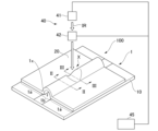
- FIG. 1 is a schematic perspective view of a kinematic element 100;
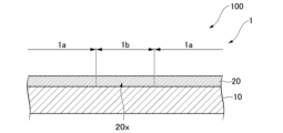
- FIG. FIG. 2 is a cross-sectional view taken along line II-II in FIG. 1;
- 2 is a cross-sectional view taken along line III-III in FIG. 1;
- FIG. 11 is a schematic cross-sectional view showing a modification of the motion element;
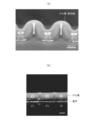
- 1 is an enlarged photograph of a laminate produced in an example.
- 4 is an enlarged photograph showing how a laminate is changed by irradiation with near-infrared light. It is an enlarged photograph which shows the mode of the change of the laminated body which scanned and irradiated the near-infrared light.
- FIG. 1 is a schematic perspective view of the motion element 100.
- FIG. 2 is a cross-sectional view taken along line II-II in FIG. 1.
- FIG. 3 is a cross-sectional view taken along line III-III in FIG. 1.
- FIG. 1 is a schematic perspective view of the motion element 100.
- FIG. 2 is a cross-sectional view taken along line II-II in FIG. 1.
- FIG. 3 is a cross-sectional view taken along line III-III in FIG. 1.
- the motion element 100 has a base material 10, a gel layer 20, and an input section 40 for inputting a stimulus to the gel layer 20.
- the base material 10 and the gel layer 20 may be collectively referred to as the laminate 1 .
- Base material 10 supports gel layer 20 .
- the modulus of rigidity of the substrate 10 is different from the modulus of rigidity of the gel layer 20 .
- the rigidity of the base material 10 is higher than that of the gel layer 20 .
- the material for forming the base material 10 various materials can be selected, regardless of whether they are organic materials or inorganic materials, as long as they do not impair the effects of the invention.
- the substrate 10 may or may not have optical transparency.
- Examples of the organic material that is the material for forming the base material 10 include polymers and elastomers.
- polymers include thermoplastic resins such as polyvinyl chloride, polystyrene, ABS resin, and polylactic acid, and thermosetting resins such as polyimide and phenol resin.
- elastomers examples include polysilicone and synthetic rubber.
- the base material 10 made of an elastomer is easily deformed according to stress.
- the gel layer 20 can be deformed as the substrate 10 is deformed.
- a gel having a degree of swelling different from that of the stimuli-responsive gel which is the material for forming the gel layer 20 described later, can also be used.
- additives may be added to the above-described organic materials, and various functions may be added to the base material 10 based on the physical properties of the additives.
- carbon nanotubes, gold nanostructures, porphyrin derivatives, polydopamine, indocyanine green, or the like may be included in organic materials to form the substrate 10 that generates heat upon receiving light.
- Inorganic materials that form the substrate 10 include glass with excellent transparency and chemical stability, conductors that generate heat when energized, magnetic metals that generate heat when stimulated by a magnetic field, and piezoelectric elements that generate electricity by stress. , a light-emitting element that emits light when energized.
- a light emitting diode can be mentioned as a light emitting element.
- the base material 10 may be subjected to various processing on at least one of the surface and the inside by known microfabrication techniques.
- the substrate 10 may have unevenness or grooves on its surface.
- the gel layer 20 is a layer formed on one surface of the substrate 10 using a stimuli-responsive gel as a forming material.
- a stimuli-responsive gel is formed from a polymer and a solvent that swells the polymer.
- the term "stimulus-responsive gel” refers to a gel that has the property of changing the retention amount (swelling degree) of the solvent retained by the gel in response to stimuli such as heat, light, electricity, and pH. "Irritation” does not include simply bringing a solvent into contact with the gel-constituting polymer or removing the solvent from the gel by drying.
- the stimulus-responsive gel may change the three-dimensional network structure of the polymer and change the degree of swelling by a stimulus that changes the molecular structure of the polymer that constitutes the gel.
- the stimuli-responsive gel may be one in which a substance contained in the gel generates heat when a stimulus is given to the substance, and the generated heat causes the solvent held by the gel to be discharged (evaporated) out of the gel. .
- the "swelling degree” refers to the volume of polymer network + solvent (original volume V 0 ) at the time of gel preparation, and the entire gel (polymer network + solvent after change) when the solvent content changes. It is represented by the ratio (V/V 0 ) of the volume (V) of .
- the degree of swelling is strongly influenced by the molecular structure of the polymer (kind, quantity, position of functional groups, three-dimensional structure, crosslink density).
- the amount of solvent that the polymer can hold changes depending on the input stimulus.
- stimuli-responsive gels include stimuli-responsive hydrogels that can be swollen with aqueous solvents and stimuli-responsive organogels (stimulus-responsive elastomers) that can swell with lipophilic solvents.
- stimulus-responsive hydrogel As the polymer contained in the stimulus-responsive hydrogel, a polymer whose molecular structure changes (responds) to various stimuli such as those described below can be used.
- Polymers that respond to heat include Lower Critical Solution Temperature (LCST) type polymers and Upper Critical Solution Temperature (UCST) type polymers.
- LCST Lower Critical Solution Temperature
- UST Upper Critical Solution Temperature
- LCST-type polymers include poly(N-isopropylacrylamide) and poly(methyl vinyl ether).
- the gel layer 20 contains an LCST-type polymer, when the swollen gel layer 20 is heated, it releases the solvent and shrinks.
- UCST-type polymers include poly(allylamine-co-allylurea).
- the gel layer 20 contains a UCST-type polymer, when the gel layer 20 is heated, it absorbs a solvent from the surroundings and swells.
- Polymers that respond to pH include polymer electrolytes obtained by polymerizing anionic monomers or cationic monomers.
- a change in pH causes a change in the charged state of the functional groups, which induces a change in the osmotic pressure inside the gel, and absorbs solvent from the surroundings to counteract the change. and swell.
- the gel layer 20 may include a water-soluble photoacid generator (diphenyl-2,4,6-trimethylphenylsulfonium p-toluenesulfonate) or a photobase generator (1,2-diisopropyl-3-[bis( By supporting dimethylamino)methylene]guanidium (2-(3-benzoylphenyl)propionate), a pH change can be locally induced by light irradiation.
- a water-soluble photoacid generator diphenyl-2,4,6-trimethylphenylsulfonium p-toluenesulfonate
- a photobase generator 1,2-diisopropyl-3-[bis( By supporting dimethylamino)methylene]guanidium (2-(3-benzoylphenyl)propionate), a pH change can be locally induced by light irradiation.
- Polymers that respond to light include polymers that have spiropyran or azobenzene in their skeletons.
- a molecular structure in which an inclusion complex of azobenzene and cyclodextrin is used as a cross-linking point may be introduced into the polymer that responds to light.
- a polymer having such a molecular structure can change the degree of swelling by changing the cross-linking point by light stimulation.
- a polymer that incorporates DNA or protein as a cross-linking point may be used as a polymer to which a biomolecule responds.
- the gel layer 20 contains macromolecules that respond to biomolecules, crosslinks by DNA or proteins are denatured (destroyed) or formed by thermal denaturation, pH change, etc., thereby changing the crosslink density of the gel and allowing permeation. Swelling (de-swelling) accompanying pressure change is induced.
- a temperature-responsive polymer gel compounded with magnetic particles such as iron
- magnetic particles such as iron
- the magnetic particles placed in the magnetic field generate heat due to magnetic induction heating, and the temperature responsive polymer changes in swelling degree in response to the heat, resulting in a volume change.
- a temperature-responsive polymer gel compounded with a microwave-absorbing material may also be used as the microwave-responsive gel.
- a microwave-absorbing material such as polyaniline
- the microwave absorbing material generates heat when irradiated with microwaves, and the temperature responsive polymer changes in swelling degree in response to the heat, resulting in a volume change.
- a hydrogel that responds to multiple stimuli may be formed by mixing a plurality of the above-described polymers.
- aqueous solvents include water and co-solvents containing water as a main component and water-miscible liquids (ionic liquids, dimethylsulfoxide, dimethylformamide, methanol, ethanol, acetone, etc.).
- the stimulus-responsive hydrogel may form an interpenetrating network structure. Specifically, after forming a gel containing a polymer having a first network structure, the gel is swollen in an aqueous solution containing components (monomer, cross-linking agent, initiator) that form the second network structure. . Thereafter, the components forming the second network are polymerized to form the second network in an interpenetrating manner with the first network to form an interpenetrating network. By forming such a structure, the mechanical strength can be increased.
- the method of synthesizing the polymer contained in the hydrogel is not particularly limited.
- an acrylic polymer chemical cross-linking by a polymerization reaction of acrylic groups can be used.
- polysaccharides and proteins gelation by physical bonding may be used, or chemical cross-linking agents typified by glutaraldehyde may be used.
- the type of polymerization reaction when polymerizing an acrylic monomer is not particularly limited, but radical polymerization using a water-soluble photopolymerization initiator can be mentioned as an example.
- Water-soluble photoinitiators include 2-oxoglutaric acid, 4′-(2-hydroxyethoxy)-2-hydroxy-2-methylpropiophenone (Irgacure 2959), phenyl(2,4,6-trimethylbenzoyl)phosphine lithium acid (LAP), 2,2′-azobis[2-methyl-N-(2-hydroxyethyl)propionamide] (VA-086) and the like.
- Thermal polymerization initiators include ammonium peroxodisulfate (APS) and potassium peroxodisulfate (KPS). It may also be combined with a polymerization accelerator, N,N,N',N'-tetramethylethane-1,2-diamine (TEMED).
- APS ammonium peroxodisulfate
- KPS potassium peroxodisulfate
- TEMED N,N,N',N'-tetramethylethane-1,2-diamine
- an oxygen scavenger may be added to the reaction system to prevent polymerization inhibition due to oxygen.
- Oxygen scavengers can include a combination of glucose and glucose oxidase. Radical polymerization may also be carried out under an inert gas atmosphere such as nitrogen or argon.
- a stimuli-responsive organogel is formed from a polymer (elastomer) and a photothermal conversion material that generates heat upon receiving light.
- Polymers (elastomers) contained in stimulus-responsive organogels include silicones such as polydimethylsiloxane, synthetic rubbers such as butadiene rubber, chloroprene rubber, isoprene rubber, acrylic rubber, and urethane rubber, natural rubber, polyethylene, poly Examples include thermoplastic resins such as vinyl chloride, polypropylene, polystyrene, polymethyl methacrylate, and polyethylene terephthalate, and thermosetting resins such as phenol-based and epoxy-based resins. These resins can induce a volume change by changing the solvent content due to drying or the like.
- Photothermal conversion materials include metal nanoparticles, carbon materials, and conductive polymers. Inside the stimulus-responsive organogel, the photothermal conversion material is dispersed in such a size that it can receive the irradiated light.
- solvents contained in stimuli-responsive organogels examples include methanol, ethanol, acetone, dimethylsulfoxide, dimethylformamide, ethyl acetate, chloroform, tetrahydrofuran, benzene, toluene, xylene, pyridine, carbon disulfide, ethylene glycol and glycerol.
- additives can be added to the stimuli-responsive gel as long as they do not inhibit gel formation.
- additives for example, biomolecules that improve biocompatibility, silver nanoparticles and surfactants for expressing antibacterial properties, ionic liquids and conductive polymers for increasing conductivity, and reacting to magnetic fields
- magnetic nanoparticles can be used. Any function can be imparted to the hydrogel by adding these additives to the hydrogel.
- a heat conversion material may be added as an additive.
- a material that generates heat upon receiving light photothermal conversion material
- the gel layer 20 can generate heat by irradiating the gel layer 20 with light.
- Thermal conversion materials include graphene, graphene oxide, metal nanoparticles, and polydopamine.
- a polymer contained in a stimuli-responsive gel a polymer that changes its molecular structure upon thermal stimulation is combined with a photothermal conversion material that generates heat in response to light.
- a heat stimulus responsive gel can be obtained.
- the shape of the gel layer 20 is not particularly limited, and various shapes can be selected according to usage patterns.
- the gel layer 20 can be, for example, film-shaped, plate-shaped, or block-shaped. Among these shapes, when it is desired to induce hollow shape deformation, a film shape is more preferable from the viewpoint of enabling large deformation with a small force.
- the thickness of the gel layer 20 is not particularly limited, it is preferably a thickness that maintains structural strength to the extent that it does not collapse under its own weight.
- the thickness is preferably 10 to 1000 ⁇ m.
- the thickness of the gel layer 20 is more preferably 60 to 600 ⁇ m, because it enables quick response and maintains structural strength.
- the mechanical properties of the gel layer 20 are determined by (1) chemically cross-linking the polymer that constitutes the gel, (2) physically cross-linking the polymer that constitutes the gel, or (3) increasing the concentration of the polymer contained in the gel. can be improved by performing one or more of
- the laminate 1 includes, at the interface between the base material 10 and the gel layer 20, an adhesion area 1a where the base material 10 and the gel layer 20 are adhered, a non-adhesion area 1b where the base material 10 and the gel layer 20 are not adhered, is formed.
- the non-adhesive region 1b is provided in a strip shape on one surface of the base material 10.
- the bonding areas of the laminate 1 are provided on both sides in the extending direction of the non-bonding area 1b in plan view (in a field of view along the normal to the base material 10).
- the pattern of the bonding area 1a and the non-bonding area 1b shown in FIG. 1 is an example, and various pattern shapes can be adopted according to the design.
- the input unit 40 non-contactly inputs a stimulus to which the stimulus-responsive gel constituting the gel layer 20 responds to an arbitrary position of the gel layer 20 .
- the input unit 40 has a stimulation unit 41 , an adjustment unit 42 and a control unit 45 .
- the stimulation unit 41 applies a stimulation to the gel layer 20 to which the stimulation-responsive gel that constitutes the gel layer 20 reacts.
- Types of stimulation can include, for example, light, magnetic fields, microwaves, and sound waves.
- the stimulation unit 41 has a configuration capable of applying each stimulation. For example, when the stimulation unit 41 applies light as stimulation, the stimulation unit 41 uses a light source that emits the light.
- the adjustment section 42 arbitrarily adjusts the position of the stimulation applied to the gel layer 20 by the stimulation section 41 .
- the adjustment unit 42 may adjust the position of stimulation by moving the stimulation unit 41, or may directly control the stimulation emitted from the stimulation unit 41 to adjust the position of stimulation.
- the adjustment unit 42 may be a servo motor that changes the position of the light source that is the stimulation unit 41, or a galvanometer that controls the direction of light emitted from the light source.
- An optical system such as a mirror may be used.
- the control unit 45 controls operations of the stimulation unit 41 and the adjustment unit 42 .
- the input unit 40 shown in FIG. 1 irradiates an arbitrary position X of the gel layer 20 with the infrared rays IR emitted from the stimulation unit 41, which is a laser light source, using the adjustment unit 42, which is a galvanomirror.
- the motion element 100 configured as above is driven as follows. In the following description, it is assumed that the gel layer 20 is a heat-stimulus-responsive hydrogel, and the heat-stimulus-responsive hydrogel contains an LCST-type polymer.
- the gel layer 20 is not fixed to the base material 10 in the non-bonded area 1b, but is fixed to the base material 10 in the bonded area 1a.
- the portion of the gel layer 20 that overlaps the non-bonded region 1b in plan view is denoted by reference numeral 20x (gel layer 20x).
- the gel layer 20 When such a motion element 100 is immersed in, for example, a solvent contained in the stimuli-responsive gel that forms the gel layer 20, the gel layer 20 swells and increases in volume isotropically. At this time, the gel layer 20x can be freely stretched in the direction in which the non-adhesive region 1b extends and in the direction away from the substrate 10 when the gel layer 20x increases in volume due to swelling.
- the gel layer 20 is fixed to the substrate 10 at the adhesive areas 1a located on both sides of the non-adhesive area 1b. Therefore, when the volume of the gel layer 20x increases due to swelling, the extension of the gel layer 20x in the direction intersecting with the extending direction of the non-bonded region 1b is restricted, and the internal pressure increases as the volume increases.
- the gel layer 20x buckles in the direction away from the base material 10 and swells greatly in order to alleviate the increase in internal pressure due to the increase in volume.
- the motion element 100 is formed with a tubular portion 20a having a channel 1x surrounded by the gel layer 20x and the base material 10. As shown in FIG.
- the shape of the conduit 1x can be controlled by controlling the pattern shape of the adhesive area 1a and the non-adhesive area 1b.
- the shape of the conduit 1x can be controlled by adjusting the type of the gel layer 20, the ratio of the rigidity of the base material 10 and the rigidity of the gel layer 20, the thickness of the gel layer 20, and the like.
- the rigidity modulus of the gel layer 20 and the swelling rate of the gel layer 20 can be controlled by changing the type of polymer monomer constituting the gel layer 20 and the type and amount of the cross-linking agent used.
- the tubular part 20a (gel layer 20x) is heated at the position X irradiated with infrared rays IR, which is thermal stimulation, by the input part 40 . Due to the heating, the LCST type polymer, which is a thermostimulable polymer, and water undergo phase separation in the gel layer 20x, and the gel layer 20x shrinks. As a result, as shown in FIG. 3, at the position X irradiated with the infrared rays IR, the pipeline 1x is closed and the gel layer 20x functions as a shutoff valve for the tubular portion 20a.
- the change in shape as described above is caused by the difference between the swelling rate of the gel layer 20 to which heat stimulation is not applied and the swelling rate of the gel layer 20 to which heat stimulation is applied at position X.
- the change in the gel layer 20 before and after applying heat stimulation is reversible. That is, when the thermal stimulation at the position X is stopped, the gel layer 20 of the motion element 100 immersed in the solvent absorbs the surrounding solvent and swells again, forming the tubular portion 20a at the position X as well. As a result, at position X, line 1x is opened again as shown in FIG.
- the deformation of the gel layer 20x is caused by two factors: (i) an increase in the volume of the entire gel layer 20 due to swelling of the stimulus-responsive gel, and (ii) buckling of the gel layer 20x whose elongation is restricted. . Therefore, compared to the gel layer 20 overlapping the adhesive region 1a, for example, where the gel layer 20x is deformed only by the factor (i), the amount of deformation (the height of the gel layer 20x before and after the stimulus response) difference in height H) increases.
- the swelling rate of the gel layer 20 can be controlled by a stimulus locally input to the gel layer 20, and the opening and closing of the tubular portion 20a (duct 1x) can be controlled.
- the laminate 1 of the motion element 100 can be manufactured by the following method. A case where the polymer contained in the stimulus-responsive gel is an acrylic polymer will be described as an example.
- Method 1 First, the surface of the base material 10 is surface-treated with a known silane coupling agent having a functional group polymerizable with an acrylic monomer.
- a (meth)acrylic group can be exemplified as a functional group possessed by the silane coupling agent.
- silane coupling agent 3-(methacryloyloxy)propyltrimethoxysilane, for example, can be used as the silane coupling agent.
- the surface of the substrate 10 can be treated with a silane coupling agent by washing the surface of the substrate 10 with an aqueous sodium hydroxide solution, treating with oxygen plasma or a piranha solution, and then applying a silane coupling agent.
- Piranha solution is a common name for a mixture of concentrated sulfuric acid and aqueous hydrogen peroxide.
- a mask of photoresist is formed using a known photolithography technique, and mask plasma treatment is performed with the pattern of the non-bonded region 1b to correspond to the non-bonded region 1b. Remove the silane coupling agent at the position where Thereby, a pattern of regions where the silane coupling agent is formed is formed.
- the laminate 1 having the gel layer 20 is obtained.
- the laminate 1 has an adhesive area 1a and a non-adhesive area 1b according to the pattern of the silane coupling agent.
- Method 2 When the material of the substrate 10 is an elastomer or a polymer film that swells with an organic solvent, first, an initiator solution is prepared by dissolving a hydrogen abstraction type photoinitiator in an organic solvent, and the initiator solution is applied to the substrate 10. to swell the initiator solution across the substrate 10 .
- Organic solvents include ethanol and acetone.
- Hydrogen abstraction type photoinitiators include benzophenone, Michler's ketone, Michler's ethyl ketone, and the like.
- the substrate 10 containing the initiator solution is pattern-exposed to consume the photoinitiator contained in the substrate 10 in a predetermined pattern.
- the acrylic monomer is radically polymerized using a photopolymerization initiator.
- the photopolymerization initiator reacts to obtain an acrylic polymer.
- the hydrogen abstraction type photoinitiator reacts with light irradiation and abstracts hydrogen atoms from the polymer constituting the base material 10 .
- reaction points (radicals) for radical polymerization are generated in the polymer constituting the base material 10 .
- reaction points generated in the base material 10 react with the radicals of the acrylic monomer and the radicals of the acrylic polymer (oligomer) generated by the radical polymerization, and the acrylic polymer is introduced into the base material 10.
- the acrylic polymer Since the photoinitiator contained in the base material 10 is consumed according to the pattern of the pattern exposure, the acrylic polymer is not introduced into the base material 10 in the pattern-exposed areas, and the pattern-exposed areas are not exposed. , an acrylic polymer is introduced into the substrate 10 .
- the laminate 1 has an adhesive area 1a and a non-adhesive area 1b according to pattern exposure.
- Method 3 In method 2, after the initiator solution is swollen on the entire substrate 10, the photoinitiator is consumed by pattern exposure to form a pattern of the photoinitiator contained in the substrate 10, but other methods are also possible. Adoptable.
- a pattern of water- and oil-repellent functional groups is formed on the surface of the substrate 10 in advance.
- the pattern of the water-repellent and oil-repellent functional groups is formed by, for example, surface-treating the substrate 10 with a silane coupling agent such as trichloro(1H,1H,2H,2H-heptadecafluorodecyl)silane, and subjecting it to the mask plasma treatment described above.
- a silane coupling agent such as trichloro(1H,1H,2H,2H-heptadecafluorodecyl)silane
- the above-described initiator solution is applied to the surface of the substrate 10 on which the pattern of the water-repellent and oil-repellent functional groups has been formed.
- the initiator solution is repelled and swelling of the substrate 10 is suppressed. Thereby, a pattern of the photoinitiator contained in the substrate 10 can be formed.
- an acrylic polymer may be polymerized in advance and then introduced to the surface of the base material 10 .
- Method 4 First, using the method described in Method 1 above, the surface of the substrate 10 is pattern-treated with a known silane coupling agent having a reactive functional group (such as an amino group or an epoxy group).
- a known silane coupling agent having a reactive functional group such as an amino group or an epoxy group.
- network-invading polymers include chitosan, alginic acid, and polyvinyl alcohol.
- the stimuli-responsive gel is brought into contact with the substrate 10 on which the network-invading polymer pattern is formed.
- the network-invading polymer penetrates inside the network structure of the stimuli-responsive gel.
- the network-invading polymer is crosslinked by changing its chemical structure by changing the pH or by diffusing and reacting with a low-molecular-weight crosslinking agent.
- the network-invading polymer forms a network inside the network structure of the stimuli-responsive gel and entangles with the stimuli-responsive gel, thereby creating a physical gap between the stimuli-responsive gel and the network-invading polymer.
- a physical or chemical bond is formed.
- the laminate 1 can be obtained by bonding the stimulation-responsive gel and the base material 10 together.
- the laminate 1 has an adhesive area 1a and a non-adhesive area 1b according to the pattern of the network-invading polymer.
- a cyanoacrylate-based adhesive may be applied to the surface of the substrate 10 in a predetermined pattern using a known method, and a stimulation-responsive gel sheet molded into a predetermined shape may be brought into contact. Thereby, the laminate 1 can be obtained by bonding the stimulation-responsive gel sheet and the substrate 10 together.
- the laminate 1 has an adhesive area 1a and a non-adhesive area 1b according to the adhesive pattern.
- the motion elements of the present invention are not limited to the configurations described above.
- the motion element can have various functions according to the formation pattern of the non-bonded areas.
- the input unit 40 may be capable of controlling scanning of stimulation (infrared IR) input to the gel layer 20 .
- the motion element 100 can continuously move the position X where the stimulus is input along the channel 1x.
- Such a motion element 100 can be used as a pump that continuously moves the position where the duct 1x is closed and pushes out the contents of the duct 1x in the scanning direction of stimulation.
- the input section 40 has one stimulation section 41, and the stimulation is input to one location (position X) of the gel layer 20, but the present invention is not limited to this.
- the motion element may have a configuration in which the input section 40 has a plurality of stimulating sections 41 and stimuli can be input to a plurality of locations at the same time.
- FIG. 4 is a schematic cross-sectional view showing a modification of the motion element, corresponding to FIGS.
- the motion element 200 of FIG. 4 has a substrate 10 , a gel layer 21 provided on the surface of the substrate 10 , and an input section (not shown) for inputting a stimulus to the gel layer 21 .
- a layered body 2 is formed by combining the base material 10 and the gel layer 21 .
- the laminate 2 includes, at the interface between the base material 10 and the gel layer 21, an adhesion area 2a where the base material 10 and the gel layer 21 are adhered, a non-adhesion area 2b where the base material 10 and the gel layer 21 are not adhered, is formed.
- the gel layer 21 may be a single layer entirely made of biocompatible stimuli-responsive gel, and has a laminated structure of a stimuli-responsive gel layer and a biocompatible material layer covering the surface of the stimuli-responsive gel layer. You may
- scaffolding proteins such as collagen and laminin can be used as biocompatible materials.
- Lamination methods include a physical adsorption method in which a substrate on which a gel layer is formed is impregnated with a scaffold protein solution, and a preformed stimuli-responsive gel layer on which Sulfo-SANPAH (sulfosuccinimidyl 6-(4'-azido -2'-nitrophenylamino)hexanoate) or other chemical fixation method can be used.
- Sulfo-SANPAH sulfosuccinimidyl 6-(4'-azido -2'-nitrophenylamino)hexanoate
- the gel layer 21 of the motion element 200 When the gel layer 21 of the motion element 200 is swollen, the gel layer 21 that overlaps the non-adhesive region 2b is deformed and largely lifted from the substrate 10, as shown in FIG. 4(a). In this state, the cells C are seeded on the surface of the gel layer 21 , immersed in a medium and cultured, whereby the cells C can be cultured on the surface of the gel layer 21 .
- the degree of swelling of the gel layer 21 overlapping the non-adhesive region 2b increases as shown in FIG. 4(b). It changes, for example, it shrinks until it flattens out.
- the surface area of the gel layer 21 overlapping the non-bonded region 2b is reduced with the volume change.
- the plurality of cells C cultured on the surface of the gel layer 21 are pressed against each other with their distances narrowed in the direction crossing the non-adhesion region 2b.
- the motion element 200 can be used as a cell culture substrate capable of applying mechanical stimulation to the cells C to be cultured.
- a motor element 200 is suitable for culturing myoblasts and vascular endothelial cells whose activities and secretions are changed by stretching stimulation.
- a silane coupling agent (3-(methacryloyloxy)propyltrimethoxysilane) having an adhesive functional group was applied to the plasma-treated surface of the glass substrate.
- a positive photoresist was spin-coated on the surface of the glass substrate coated with the silane coupling agent to form a resist layer.
- a resist layer having an opening with a width of 1 mm was formed by irradiating a strip having a line width of 1 mm through a mask with ultraviolet rays having a peak wavelength in the absorption wavelength band of the positive photoresist used and developing it.
- the resist layer was removed with acetone to obtain a substrate on which a pattern of adhesive functional groups was formed.
- the area where the pattern of adhesive functional groups is formed corresponds to the adhesive area.
- the region overlapping the opening of the resist layer has the adhesive functional group removed by oxygen plasma treatment, and corresponds to the non-adhesive region.
- the monomer solution includes N-isopropylacrylamide (2 mol/L) as a monomer, methylenebisacrylamide (0.02 mol/L) as a cross-linking agent, LAP (0.002 mol/L) as a photopolymerization initiator, and additives. It was an aqueous dispersion containing a certain gold nanorod (0.1% by mass of the total monomer liquid).
- a cover glass (seal substrate) treated with oxygen plasma was placed to cover the monomer solution, and the monomer solution was sandwiched between the base material and the seal substrate. After wiping off excess monomer liquid, ultraviolet rays (365 nm) were irradiated to polymerize the monomer liquid.
- the seal substrate was removed and immersed in a large excess amount of pure water to remove unreacted gel precursor molecules to obtain a laminate of the motion element of the example.
- Fig. 5 is an enlarged photograph of the laminate produced by the above method, Fig. 5(a) being a plan photograph and Fig. 5(b) being a side photograph.
- the gel layer of the laminate is formed in a wavy curve. This curved portion is located in a portion of the gel layer that overlaps the non-adhesive region, and is formed with a conduit in the same manner as the tubular portion shown in FIG.
- a light source that emits near-infrared light and a control device that controls the light source correspond to the input section of the present invention.
- FIG. 6 is an enlarged photograph showing how the laminate is changed by irradiation with near-infrared light.
- the photograph shown in FIG. 6 is a side view photograph taken through a long wavelength cut filter.
- a part of the three-dimensional structure (tubular part) can be changed by using light irradiation as a switch, and that the light-irradiated part functions as a dynamic valve that can be opened and closed. .
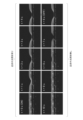
- FIG. 7 is an enlarged photograph (planar photograph) showing how a laminate irradiated with scanning near-infrared light changes.
- near-infrared rays were irradiated to the tubular part near the air bubbles in a state where the air bubbles were put in the pipe.
- arrows indicate the positions of bubbles in the conduit.
- the tubular part of the laminate When the tubular part of the laminate is irradiated with near-infrared light, the tubular part shrinks as shown in FIG. As shown in FIGS. 7A to 7D, when the near-infrared light was scanned along the tubular portion, it was confirmed that the bubbles also moved along with the scanning of the near-infrared light. Since the duct in the part irradiated with the near-infrared light is closed, and the closed part of the duct is moved by the scanning of the near-infrared light, the bubbles in the duct are pushed out to the closed part of the duct. It is thought that it moved with
- the fabricated kinetic element can transport liquids and solids contained in the channel using light irradiation as a switch.
- the motion element according to the present invention is useful as an actuation device that makes use of high-speed large deformation of a three-dimensional shape, and can be applied to a wide range of fields such as fluidics, micropumps, cell culture, adhesion control, friction control, and wettability control. be.
Landscapes
- Engineering & Computer Science (AREA)
- Chemical & Material Sciences (AREA)
- General Engineering & Computer Science (AREA)
- Combustion & Propulsion (AREA)
- Mechanical Engineering (AREA)
- Computer Hardware Design (AREA)
- Microelectronics & Electronic Packaging (AREA)
- Dispersion Chemistry (AREA)
- Health & Medical Sciences (AREA)
- Toxicology (AREA)
- Laminated Bodies (AREA)
- Micromachines (AREA)
Priority Applications (3)
| Application Number | Priority Date | Filing Date | Title |
|---|---|---|---|
| PCT/JP2021/047496 WO2023119467A1 (ja) | 2021-12-22 | 2021-12-22 | 運動素子 |
| US18/721,581 US20250101964A1 (en) | 2021-12-22 | 2021-12-22 | Motion element |
| JP2023568864A JPWO2023119467A1 (https=) | 2021-12-22 | 2021-12-22 |
Applications Claiming Priority (1)
| Application Number | Priority Date | Filing Date | Title |
|---|---|---|---|
| PCT/JP2021/047496 WO2023119467A1 (ja) | 2021-12-22 | 2021-12-22 | 運動素子 |
Publications (1)
| Publication Number | Publication Date |
|---|---|
| WO2023119467A1 true WO2023119467A1 (ja) | 2023-06-29 |
Family
ID=86901696
Family Applications (1)
| Application Number | Title | Priority Date | Filing Date |
|---|---|---|---|
| PCT/JP2021/047496 Ceased WO2023119467A1 (ja) | 2021-12-22 | 2021-12-22 | 運動素子 |
Country Status (3)
| Country | Link |
|---|---|
| US (1) | US20250101964A1 (https=) |
| JP (1) | JPWO2023119467A1 (https=) |
| WO (1) | WO2023119467A1 (https=) |
Cited By (1)
| Publication number | Priority date | Publication date | Assignee | Title |
|---|---|---|---|---|
| WO2025224796A1 (ja) * | 2024-04-22 | 2025-10-30 | Ntt株式会社 | 自律移動型デバイス、自律移動型デバイスの製造方法 |
Citations (6)
| Publication number | Priority date | Publication date | Assignee | Title |
|---|---|---|---|---|
| JP2002163022A (ja) * | 2000-11-29 | 2002-06-07 | Japan Science & Technology Corp | マイクロシステムにおける流れの制御方法 |
| JP2007147001A (ja) * | 2005-11-29 | 2007-06-14 | Yokohama National Univ | 送液システム |
| JP2007319942A (ja) * | 2006-05-30 | 2007-12-13 | Fuji Xerox Co Ltd | マイクロ流路デバイス |
| JP2009245035A (ja) * | 2008-03-31 | 2009-10-22 | Kazusa Dna Kenkyusho | マイクロシステムにおける流体の制御方法 |
| JP2020062843A (ja) * | 2018-10-18 | 2020-04-23 | 日本電信電話株式会社 | 積層体、積層体の製造方法および形状制御デバイス |
| WO2021079399A1 (ja) * | 2019-10-21 | 2021-04-29 | 日本電信電話株式会社 | ハイドロゲル流体デバイス、ハイドロゲル流体デバイスの製造方法 |
-
2021
- 2021-12-22 US US18/721,581 patent/US20250101964A1/en active Pending
- 2021-12-22 JP JP2023568864A patent/JPWO2023119467A1/ja active Pending
- 2021-12-22 WO PCT/JP2021/047496 patent/WO2023119467A1/ja not_active Ceased
Patent Citations (6)
| Publication number | Priority date | Publication date | Assignee | Title |
|---|---|---|---|---|
| JP2002163022A (ja) * | 2000-11-29 | 2002-06-07 | Japan Science & Technology Corp | マイクロシステムにおける流れの制御方法 |
| JP2007147001A (ja) * | 2005-11-29 | 2007-06-14 | Yokohama National Univ | 送液システム |
| JP2007319942A (ja) * | 2006-05-30 | 2007-12-13 | Fuji Xerox Co Ltd | マイクロ流路デバイス |
| JP2009245035A (ja) * | 2008-03-31 | 2009-10-22 | Kazusa Dna Kenkyusho | マイクロシステムにおける流体の制御方法 |
| JP2020062843A (ja) * | 2018-10-18 | 2020-04-23 | 日本電信電話株式会社 | 積層体、積層体の製造方法および形状制御デバイス |
| WO2021079399A1 (ja) * | 2019-10-21 | 2021-04-29 | 日本電信電話株式会社 | ハイドロゲル流体デバイス、ハイドロゲル流体デバイスの製造方法 |
Cited By (1)
| Publication number | Priority date | Publication date | Assignee | Title |
|---|---|---|---|---|
| WO2025224796A1 (ja) * | 2024-04-22 | 2025-10-30 | Ntt株式会社 | 自律移動型デバイス、自律移動型デバイスの製造方法 |
Also Published As
| Publication number | Publication date |
|---|---|
| US20250101964A1 (en) | 2025-03-27 |
| JPWO2023119467A1 (https=) | 2023-06-29 |
Similar Documents
| Publication | Publication Date | Title |
|---|---|---|
| JP7071641B2 (ja) | 積層体、積層体の製造方法および形状制御デバイス | |
| JP7208569B2 (ja) | ハイドロゲル流体デバイス、ハイドロゲル流体デバイスの製造方法 | |
| Zhang et al. | Versatile surface modification of hydrogels by surface-initiated, Cu0-mediated controlled radical polymerization | |
| Hu et al. | Surface modification of poly (dimethylsiloxane) microfluidic devices by ultraviolet polymer grafting | |
| Hribar et al. | Light-assisted direct-write of 3D functional biomaterials | |
| Peppas et al. | Hydrogels in biology and medicine: from molecular principles to bionanotechnology | |
| Ebara et al. | Surface modification of microfluidic channels by UV-mediated graft polymerization of non-fouling and ‘smart’polymers | |
| Di Benedetto et al. | Patterning polyacrylamide hydrogels by soft lithography | |
| Gao et al. | Synergistic pH and temperature-driven actuation of poly (NIPAM-co-DMAPMA)/clay nanocomposite hydrogel bilayers | |
| Li et al. | Programmable Dual‐Responsive Actuation of Single‐Hydrogel‐Based Bilayer Actuators by Photothermal and Skin Layer Effects with Graphene Oxides | |
| Guzman et al. | High strength bimodal amphiphilic conetworks for immunoisolation membranes: Synthesis, characterization, and properties | |
| De France et al. | 2.5 D hierarchical structuring of nanocomposite hydrogel films containing cellulose nanocrystals | |
| US20190185629A1 (en) | Polymeric devices and methods of making | |
| KR20150137178A (ko) | 입자 정렬을 이용한 코팅 방법 | |
| WO2023119467A1 (ja) | 運動素子 | |
| Park et al. | Air-stable aerophobic polydimethylsiloxane tube with efficient self-removal of air bubbles | |
| Mohania et al. | Fabrication and characterization of porous poly (dimethylsiloxane)(PDMS) adhesives | |
| Luo et al. | Near-infrared responsive gecko-inspired flexible arm gripper | |
| JP4549410B2 (ja) | 高分子ゲル複合体、及びその製造方法 | |
| Xiong et al. | Fast solvent-driven micropump fabricated by two-photon microfabrication | |
| Kozlovskaya et al. | Architecture of Hydrated Multilayer Poly (methacrylic acid) Hydrogels: The Effect of Solution pH | |
| Bayat et al. | Geometrical Constraints of Poly (diethylene glycol methyl ether methacrylate) Brushes on Spherical Nanoparticles and Cylindrical Nanowires: Implications for Thermoresponsive Brushes on Nanoobjects | |
| Gallardo et al. | Chemical and topographical modification of polycarbonate surfaces through diffusion/photocuring processes of hydrogel precursors based on vinylpyrrolidone | |
| JP7717316B2 (ja) | ハイドロゲル流体デバイスおよびハイドロゲル流体デバイスの製造方法 | |
| Chen et al. | Fabricating polymer canopies onto structured surfaces using liquid scaffolds |
Legal Events
| Date | Code | Title | Description |
|---|---|---|---|
| 121 | Ep: the epo has been informed by wipo that ep was designated in this application |
Ref document number: 21968904 Country of ref document: EP Kind code of ref document: A1 |
|
| ENP | Entry into the national phase |
Ref document number: 2023568864 Country of ref document: JP Kind code of ref document: A |
|
| WWE | Wipo information: entry into national phase |
Ref document number: 18721581 Country of ref document: US |
|
| NENP | Non-entry into the national phase |
Ref country code: DE |
|
| 122 | Ep: pct application non-entry in european phase |
Ref document number: 21968904 Country of ref document: EP Kind code of ref document: A1 |
|
| WWP | Wipo information: published in national office |
Ref document number: 18721581 Country of ref document: US |