WO2023119429A1 - アンテナ装置、無線電力伝送装置、及び無線電力伝送システム - Google Patents
アンテナ装置、無線電力伝送装置、及び無線電力伝送システム Download PDFInfo
- Publication number
- WO2023119429A1 WO2023119429A1 PCT/JP2021/047366 JP2021047366W WO2023119429A1 WO 2023119429 A1 WO2023119429 A1 WO 2023119429A1 JP 2021047366 W JP2021047366 W JP 2021047366W WO 2023119429 A1 WO2023119429 A1 WO 2023119429A1
- Authority
- WO
- WIPO (PCT)
- Prior art keywords
- power transmission
- antenna
- antenna device
- wireless power
- coil
- Prior art date
- Legal status (The legal status is an assumption and is not a legal conclusion. Google has not performed a legal analysis and makes no representation as to the accuracy of the status listed.)
- Ceased
Links
Images





Classifications
-
- H—ELECTRICITY
- H02—GENERATION; CONVERSION OR DISTRIBUTION OF ELECTRIC POWER
- H02J—ELECTRIC POWER NETWORKS; CIRCUIT ARRANGEMENTS OR SYSTEMS FOR SUPPLYING OR DISTRIBUTING ELECTRIC POWER; SYSTEMS FOR STORING ELECTRIC ENERGY
- H02J50/00—Circuit arrangements or systems for wireless supply or distribution of electric power
- H02J50/20—Circuit arrangements or systems for wireless supply or distribution of electric power using microwaves or radio frequency waves
-
- H—ELECTRICITY
- H02—GENERATION; CONVERSION OR DISTRIBUTION OF ELECTRIC POWER
- H02J—ELECTRIC POWER NETWORKS; CIRCUIT ARRANGEMENTS OR SYSTEMS FOR SUPPLYING OR DISTRIBUTING ELECTRIC POWER; SYSTEMS FOR STORING ELECTRIC ENERGY
- H02J50/00—Circuit arrangements or systems for wireless supply or distribution of electric power
-
- H—ELECTRICITY
- H02—GENERATION; CONVERSION OR DISTRIBUTION OF ELECTRIC POWER
- H02J—ELECTRIC POWER NETWORKS; CIRCUIT ARRANGEMENTS OR SYSTEMS FOR SUPPLYING OR DISTRIBUTING ELECTRIC POWER; SYSTEMS FOR STORING ELECTRIC ENERGY
- H02J50/00—Circuit arrangements or systems for wireless supply or distribution of electric power
- H02J50/10—Circuit arrangements or systems for wireless supply or distribution of electric power using inductive coupling
- H02J50/12—Circuit arrangements or systems for wireless supply or distribution of electric power using inductive coupling of the resonant type
Definitions
- the present invention relates to a technique for wirelessly transmitting power, and particularly to a technique effective in wirelessly transmitting power over a relatively long transmission distance of several meters or more without using a cable. .
- Patent Document 1 discloses a method (3) using magnetic field resonance or electric field resonance.
- microwaves radio waves propagate while diffusing in space, so the transmission efficiency decreases as the distance increases.
- the resonance phenomenon due to the resonance of the antennas on both the power transmission side and the power reception side is used, so if the distance between the antennas changes (that is, if the distance between the antennas is too short), or too far away), the transmission efficiency drops due to the condition of resonance.
- the present invention has been made in view of the above points, and aims to provide a technique for performing wireless power transmission more efficiently than the conventional technique.
- an antenna device for wireless power transmission is provided.
- FIG. 1 is a diagram illustrating an example of a system that performs wireless power transmission using surface waves;
- FIG. 1 is a diagram showing a configuration of an antenna device of Example 1;
- FIG. FIG. 3 is a diagram showing the configuration of a resonator;
- 1 is a diagram showing a configuration of an antenna device of Example 1;
- FIG. 1 is a diagram illustrating a configuration of a wireless power transmission system of Example 1;
- FIG. 10 is a diagram showing the configuration of the antenna device of Example 2;
- FIG. 10 is a diagram showing the configuration of the antenna device of Example 2;
- FIG. 10 is a diagram illustrating the configuration of a wireless power transmission system of Example 3;
- wireless power transmission using surface waves is performed. That is, the energy radiated from the power transmitting antenna is wirelessly transmitted to the power receiving antenna in the form of a surface wave.
- Antennas for both power transmission and power reception can use antennas of the same shape for transmitting and receiving surface waves.
- An antenna may also be called an "antenna device”.
- a surface wave is an electromagnetic wave that propagates on a two-dimensional plane along the interface of two media with different dielectric constants. Since the power (energy) of surface waves is concentrated near the interface and does not spread in the three-dimensional height direction, power can be transmitted with high efficiency between antennas near the interface.
- Air and metal floor are examples of two media with different dielectric constants that form the interface through which surface waves propagate.
- power can be efficiently wirelessly transmitted between devices placed on floors covered with metal panels in offices, factories, and the like.
- Fig. 1 shows a configuration example of a system that performs wireless power transmission using surface waves.
- a power transmitting antenna 100 and a power receiving antenna 200 which are antennas having the same shape for transmitting and receiving surface waves, are provided.
- surface waves propagate along the interface between medium A and medium B, which are two media with different dielectric constants, whereby power is wirelessly transmitted from power transmitting antenna 100 to power receiving antenna 200. .
- Example 1 In general, when an antenna resonates, both radio waves radiated into a three-dimensional space and surface waves radiated into a two-dimensional plane can be generated. In order to increase the transmission efficiency of wireless power transmission on a two-dimensional plane, it is desirable for the antenna to radiate less radio waves into a three-dimensional space and to radiate more surface waves on a two-dimensional plane.
- the structure shown in FIG. 2 realizes an antenna that reduces radiation of radio waves to a three-dimensional space and increases radiation of surface waves on a two-dimensional plane.
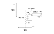
- FIG. 2 is a diagram showing the configuration of the antenna of Example 1.
- FIG. 2 shows an image of a cross section of the antenna taken along a plane perpendicular to the plane of the electrodes.
- the antenna of Example 1 includes an electrode 11 for emitting surface waves to the front medium (medium A) and an electrode 12 for coupling with the floor (medium B).
- the electrode 12 Since the electrode 12 is strongly coupled with the medium B on the floor, it is installed parallel to the floor so as to face the floor. Since the electrode 11 radiates a surface wave in a direction parallel to the interface, it is installed so as to face a direction parallel to the interface (that is, perpendicular to the electrode 12 parallel to the floor). It should be noted that “parallel” and “perpendicular” in the present embodiment may not be strictly “parallel” and “perpendicular”. For example, an orientation that deviates from “parallel” within a certain threshold may be regarded as “parallel.” Also, an orientation that deviates from "vertical” within a certain threshold may be regarded as "perpendicular".
- the electrodes 11 and 12 are connected by a coil (primary coil 13).
- a secondary coil 14 connected to the coaxial cable 15 is also provided.
- the electrodes 11 and 12 and the primary coil 13 constitute one resonator and have a unique resonance frequency.
- the sizes of the electrodes and coils are adjusted so that the resonance frequency of this resonator matches the frequency of the high-frequency power supply to be transmitted. Note that “match” does not have to be strictly “match”. For example, even if it deviates from “match” within a certain threshold range, it may be regarded as "match”.
- FIG. 3 shows a resonator formed by electrodes 11, 12, and primary coil 13.
- the resonator shown in FIG. 3 resonates, charges are accumulated in the electrodes 11 and 12 and the voltage amplitude between the electrodes 11 and 12 increases, creating a strong electric field around the electrodes.
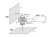
- FIG. 4 An example of the arrangement of the primary coil 13 and the secondary coil 14 is shown in FIG. In the example shown in FIG. 4, by winding the secondary coil 14 over the primary coil 13, it is possible to input/output power to/from the resonator.
- FIG. 5 shows a configuration example in which the antenna 100 is connected to a power transmission circuit and the antenna 200 is connected to a power reception circuit. Note that both the power transmission circuit and the power reception circuit may be called a power transmission/reception circuit.
- a device including an antenna and a power transmission/reception circuit may also be called a wireless power transmission device. Also, as shown in FIG. 5, a system including a plurality of wireless power transmission devices may be called a wireless power transmission system.
- the power transmission circuit has a matching circuit 101, an inverter 102, and a power supply 103.
- the power receiving circuit has a matching circuit 201 , a converter 202 and a load 203 .
- the matching circuit 101 of the power transmission circuit performs impedance matching between the antenna 100 and the inverter 102 .
- a matching circuit 201 of the power receiving circuit performs impedance matching between the antenna 200 and the converter 202 .
- the matching circuits 101 and 201 can suppress reflection and improve the transmission efficiency of the entire wireless power transmission system.
- Example 2 Next, Example 2 will be described.
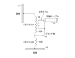
- the electrodes at both ends become “antinodes of resonance with maximum potential amplitude", and the vicinity of the center of the resonator becomes “resonance node with minimum potential amplitude”. Therefore, as shown in FIG. 6, the ground line 16 of the coaxial cable for feeding may be connected to a position where the potential is zero and becomes a resonance node (position between the primary coils 13A and 13B).
- FIG. 7 shows a diagram of the antenna shown in FIG. 6 viewed obliquely from above.
- Example 3 Next, Example 3 will be described.
- the antenna used in the third embodiment may be the antenna described in the first embodiment or the antenna described in the second embodiment.
- Wireless power transmission technology using surface waves allows power to be confined within a two-dimensional plane without being diffused in the three-dimensional height direction. It has the advantage of higher transmission efficiency than power transmission technology.
- Fig. 8 shows a system configuration example that utilizes the advantage of being able to bend the power transmission path along the interface.
- the components of the system are the same as those shown in FIG.
- the example of FIG. 8 shows the case where the other party to which power is to be sent is on the horizon or beyond the horizon line and cannot be seen by the other party. Even in such a case, it is possible to transmit power from antenna 100 to antenna 200, which could not be realized by conventional wireless power transmission techniques using lasers or microwaves.
- the antenna device for wireless power transmission includes two electrodes facing perpendicular to each other, a coil connecting them, and another coil magnetically coupled to the coil. and configured to be connected to a power transmission/reception circuit via the other coil.
- the two electrodes and the coil that connects them are resonators that resonate at the output frequency of the power transmission circuit for wireless power transmission.
- the resonator and the ground of the power transmission/reception circuit may be connected by a ground line.
- the antenna device configured as described above, it is possible to suppress the radiation of radio waves into a three-dimensional space and efficiently transmit and receive surface waves propagating on a two-dimensional plane.
- power since power is confined on a two-dimensional plane and transmitted, power can be transmitted more efficiently than conventional wireless power transmission technology that radiates power in three-dimensional spatial directions.
- the power will also be transmitted while bending along the interface, so power can be transmitted even if the other party is not directly visible.
- This specification discloses at least an antenna device, a wireless power transmission device, and a wireless power transmission system according to the following items.
- (Section 1) two electrodes oriented perpendicular to each other; a first coil connecting the two electrodes; and a second coil magnetically coupled to the first coil.
- (Section 2) 2. The antenna device according to claim 1, wherein the two electrodes and the first coil configure a resonator that resonates at an output frequency of a power transmission/reception circuit for wireless power transmission.
- (Section 3) 3.
- the antenna device according to claim 2 wherein the resonator and the ground of the power transmitting/receiving circuit are connected by a ground wire.
- Wireless power transmission comprising: the antenna device according to any one of items 1 to 4; and a power transmission/reception circuit connected to the antenna device via the second coil in the antenna device.
- a wireless power transmission system comprising: a power transmission side wireless power transmission device that is the wireless power transmission device according to claim 5; and a power reception side wireless power transmission device that is the wireless power transmission device according to claim 5.
Landscapes
- Engineering & Computer Science (AREA)
- Computer Networks & Wireless Communication (AREA)
- Power Engineering (AREA)
- Charge And Discharge Circuits For Batteries Or The Like (AREA)
Abstract
Description
前記2枚の電極を接続する第1のコイルと、
前記第1のコイルに磁界結合する第2のコイルと
を備える無線電力伝送用のアンテナ装置が提供される。
本実施の形態では、表面波を使用した無線電力伝送を行う。すなわち、送電用のアンテナから放射したエネルギーを表面波の形で受電用のアンテナまで無線で伝送する。送電用と受電用のアンテナは、どちらも表面波を送受する同じ形状のアンテナを用いることができる。なお、アンテナを「アンテナ装置」と呼んでもよい。
一般的に、アンテナが共振するとき、3次元空間に放射される電波と、2次元平面内に放射される表面波の両方が発生しうる。2次元平面上での無線電力伝送の伝送効率を上げるためには、アンテナは3次元空間への電波の放射を少なくし、2次元平面上の表面波の放射を大きくすることが望ましい。
次に、実施例2を説明する。アンテナ内部の共振器が共振するとき、両端の電極が「電位の振幅が最大の共振の腹」になり、共振器の中央付近が「電位の振幅が最小の共振の節」になる。そこで、図6に示すように、電位がゼロで共振の節となる位置(一次コイル13Aと一次コイル13Bの間の位置)に、給電用の同軸ケーブルのグランド線16を接続してもよい。
次に、実施例3を説明する。実施例3で使用するアンテナは実施例1で説明したアンテナであってもよいし、実施例2で説明したアンテナであってもよい。
以上説明したとおり、本実施の形態では、無線電力伝送用のアンテナ装置を、互いに垂直な方向を向いた2枚の電極と、それらをつなぐコイルと、そのコイルに磁界結合するもう一つのコイルを備え、当該もう一つのコイルを介して送受電回路に接続されるように構成した。
本明細書には、少なくとも下記各項のアンテナ装置、無線電力伝送装置、及び無線電力伝送システムが開示されている。
(第1項)
互いに垂直な方向を向いた2枚の電極と、
前記2枚の電極を接続する第1のコイルと、
前記第1のコイルに磁界結合する第2のコイルと
を備える無線電力伝送用のアンテナ装置。
(第2項)
前記2枚の電極と前記第1のコイルは、無線電力伝送用の送受電回路の出力周波数で共振する共振器を構成する
第1項に記載のアンテナ装置。
(第3項)
前記共振器と、前記送受電回路のグランドがグランド線によって接続されている
第2項に記載のアンテナ装置。
(第4項)
前記アンテナ装置は、表面波により電力を送電する、又は、表面波により送電された電力を受電する
第1項ないし第3項のうちいずれか1項に記載のアンテナ装置。
(第5項)
第1項ないし第4項のうちいずれか1項に記載の前記アンテナ装置と、前記アンテナ装置における前記第2のコイルを介して前記アンテナ装置に接続される送受電回路と、を備える無線電力伝送装置。
(第6項)
第5項に記載の無線電力伝送装置である送電側の無線電力伝送装置と、第5項に記載の無線電力伝送装置である受電側の無線電力伝送装置と、を備える無線電力伝送システム。
12 電極
13 1次コイル
14 2次コイル
15 同軸ケーブル
16 グランド線
100 アンテナ
101 整合回路
102 インバータ
103 電源
200 アンテナ
201 整合回路
202 コンバータ
203 負荷
Claims (6)
- 互いに垂直な方向を向いた2枚の電極と、
前記2枚の電極を接続する第1のコイルと、
前記第1のコイルに磁界結合する第2のコイルと
を備える無線電力伝送用のアンテナ装置。 - 前記2枚の電極と前記第1のコイルは、無線電力伝送用の送受電回路の出力周波数で共振する共振器を構成する
請求項1に記載のアンテナ装置。 - 前記共振器と、前記送受電回路のグランドがグランド線によって接続されている
請求項2に記載のアンテナ装置。 - 前記アンテナ装置は、表面波により電力を送電する、又は、表面波により送電された電力を受電する
請求項1ないし3のうちいずれか1項に記載のアンテナ装置。 - 請求項1ないし4のうちいずれか1項に記載の前記アンテナ装置と、前記アンテナ装置における前記第2のコイルを介して前記アンテナ装置に接続される送受電回路と、を備える無線電力伝送装置。
- 請求項5に記載の無線電力伝送装置である送電側の無線電力伝送装置と、請求項5に記載の無線電力伝送装置である受電側の無線電力伝送装置と、を備える無線電力伝送システム。
Priority Applications (3)
| Application Number | Priority Date | Filing Date | Title |
|---|---|---|---|
| PCT/JP2021/047366 WO2023119429A1 (ja) | 2021-12-21 | 2021-12-21 | アンテナ装置、無線電力伝送装置、及び無線電力伝送システム |
| US18/715,330 US20250038576A1 (en) | 2021-12-21 | 2021-12-21 | Antenna apparatus, wireless power transmission apparatus, and wireless power transmission system |
| JP2023568830A JP7758058B2 (ja) | 2021-12-21 | 2021-12-21 | アンテナ装置、無線電力伝送装置、及び無線電力伝送システム |
Applications Claiming Priority (1)
| Application Number | Priority Date | Filing Date | Title |
|---|---|---|---|
| PCT/JP2021/047366 WO2023119429A1 (ja) | 2021-12-21 | 2021-12-21 | アンテナ装置、無線電力伝送装置、及び無線電力伝送システム |
Publications (1)
| Publication Number | Publication Date |
|---|---|
| WO2023119429A1 true WO2023119429A1 (ja) | 2023-06-29 |
Family
ID=86901650
Family Applications (1)
| Application Number | Title | Priority Date | Filing Date |
|---|---|---|---|
| PCT/JP2021/047366 Ceased WO2023119429A1 (ja) | 2021-12-21 | 2021-12-21 | アンテナ装置、無線電力伝送装置、及び無線電力伝送システム |
Country Status (3)
| Country | Link |
|---|---|
| US (1) | US20250038576A1 (ja) |
| JP (1) | JP7758058B2 (ja) |
| WO (1) | WO2023119429A1 (ja) |
Cited By (1)
| Publication number | Priority date | Publication date | Assignee | Title |
|---|---|---|---|---|
| WO2025104813A1 (ja) * | 2023-11-14 | 2025-05-22 | 日本電信電話株式会社 | アンテナ、電力伝送システム |
Citations (3)
| Publication number | Priority date | Publication date | Assignee | Title |
|---|---|---|---|---|
| JP2008099235A (ja) * | 2006-09-11 | 2008-04-24 | Sony Corp | 通信システム及び通信装置 |
| WO2012086280A1 (ja) * | 2010-12-24 | 2012-06-28 | 株式会社村田製作所 | ワイヤレス電力伝送システム |
| JP2016509468A (ja) * | 2013-03-07 | 2016-03-24 | シーピージー テクノロジーズ、 エルエルシー | 損失性媒体上での誘導表面波モードの励起および使用 |
Family Cites Families (29)
| Publication number | Priority date | Publication date | Assignee | Title |
|---|---|---|---|---|
| JP3629448B2 (ja) * | 2001-07-27 | 2005-03-16 | Tdk株式会社 | アンテナ装置及びそれを備えた電子機器 |
| DE602004026549D1 (de) * | 2003-02-03 | 2010-05-27 | Panasonic Corp | Antenneneinrichtung und diese verwendende drahtlose kommunikationseinrichtung |
| EP1926223B1 (en) * | 2006-11-21 | 2018-02-28 | Sony Corporation | Communication system and communication apparatus |
| US8310200B2 (en) * | 2009-04-15 | 2012-11-13 | GM Global Technology Operations LLC | Inductive chargers and inductive charging systems for portable electronic devices |
| US20110080050A1 (en) * | 2009-10-02 | 2011-04-07 | Ut-Battelle, Llc | Systems and Methods for Directional Reactive Power Ground Plane Transmission |
| JP5838562B2 (ja) * | 2011-02-17 | 2016-01-06 | 富士通株式会社 | ワイヤレス送電装置及びワイヤレス送電システム |
| JP5802424B2 (ja) * | 2011-04-22 | 2015-10-28 | 矢崎総業株式会社 | 共鳴式非接触給電システム |
| JP5710759B2 (ja) * | 2011-06-07 | 2015-04-30 | パイオニア株式会社 | インピーダンス整合装置、制御方法 |
| AU2012306994B2 (en) * | 2011-09-07 | 2016-09-15 | Solace Power Inc. | Wireless electric field power transmission system and method |
| US20130057079A1 (en) * | 2011-09-07 | 2013-03-07 | Samsung Electronics Co., Ltd. | Apparatus and method of controlling wireless power transmission |
| KR20140091604A (ko) * | 2011-12-13 | 2014-07-21 | 야자키 소교 가부시키가이샤 | 전기적 연결부를 고정하기 위한 구조, 커넥터 및 커넥터를 연결하는 방법 |
| CN109067014B (zh) * | 2012-09-05 | 2022-04-15 | 瑞萨电子株式会社 | 非接触充电装置 |
| US9768643B2 (en) * | 2012-11-02 | 2017-09-19 | Panasonic Intellectual Property Management Co., Ltd. | Wireless power transmission system capable of continuing power transmission while suppressing heatup of foreign objects |
| KR101902920B1 (ko) * | 2012-12-11 | 2018-10-01 | 삼성전자주식회사 | 광대역 표면 플라즈몬 공진기를 포함하는 적외선 검출기 |
| JP6308371B2 (ja) * | 2013-04-22 | 2018-04-11 | パナソニックIpマネジメント株式会社 | 無線電力伝送装置 |
| JP6095507B2 (ja) * | 2013-06-28 | 2017-03-15 | オリンパス株式会社 | 内視鏡システム |
| JP6252589B2 (ja) * | 2013-07-31 | 2017-12-27 | パナソニック株式会社 | 無線送電装置及び無線電力伝送システム |
| US9281119B2 (en) * | 2013-11-13 | 2016-03-08 | The Hong Kong Polytechnic University | Three-coil topology for wireless power transfer |
| US9805864B2 (en) * | 2014-04-04 | 2017-10-31 | Apple Inc. | Inductive spring system |
| WO2015199151A1 (ja) * | 2014-06-25 | 2015-12-30 | 株式会社Ihi | コイル装置およびインダクタンス変更機構 |
| KR102388722B1 (ko) * | 2015-11-20 | 2022-04-21 | 삼성디스플레이 주식회사 | 표시 장치 및 유기 발광 표시 장치 |
| US10361586B2 (en) * | 2015-12-29 | 2019-07-23 | Motorola Solutions, Inc. | Method of wirelessly transferring power |
| JP6745134B2 (ja) * | 2016-05-12 | 2020-08-26 | 東京エレクトロン株式会社 | プラズマ処理装置 |
| KR101804683B1 (ko) * | 2016-06-20 | 2017-12-05 | 울산과학기술원 | 무선 전력 전송 시스템 및 통신 시스템 |
| US10819152B2 (en) * | 2016-09-12 | 2020-10-27 | The Research Foundation For The State University Of New York | Wireless power transfer systems and components thereof |
| KR102670579B1 (ko) * | 2020-10-27 | 2024-05-29 | 한국전자통신연구원 | 무선 전력 송신 장치 및 무선 전력 수신 장치 |
| US20240250563A1 (en) * | 2020-11-04 | 2024-07-25 | The Alfred E. Mann Foundation For Scientific Research | Automatically-aligning magnetic field system |
| JP7654823B2 (ja) * | 2021-03-30 | 2025-04-01 | アップル インコーポレイテッド | 電子デバイスにおけるワイヤレス電力伝送および通信のための磁気構成 |
| CN113300482A (zh) * | 2021-04-29 | 2021-08-24 | 伏达半导体(合肥)有限公司 | 无线电力传输设备、方法及系统 |
-
2021
- 2021-12-21 US US18/715,330 patent/US20250038576A1/en active Pending
- 2021-12-21 JP JP2023568830A patent/JP7758058B2/ja active Active
- 2021-12-21 WO PCT/JP2021/047366 patent/WO2023119429A1/ja not_active Ceased
Patent Citations (3)
| Publication number | Priority date | Publication date | Assignee | Title |
|---|---|---|---|---|
| JP2008099235A (ja) * | 2006-09-11 | 2008-04-24 | Sony Corp | 通信システム及び通信装置 |
| WO2012086280A1 (ja) * | 2010-12-24 | 2012-06-28 | 株式会社村田製作所 | ワイヤレス電力伝送システム |
| JP2016509468A (ja) * | 2013-03-07 | 2016-03-24 | シーピージー テクノロジーズ、 エルエルシー | 損失性媒体上での誘導表面波モードの励起および使用 |
Cited By (1)
| Publication number | Priority date | Publication date | Assignee | Title |
|---|---|---|---|---|
| WO2025104813A1 (ja) * | 2023-11-14 | 2025-05-22 | 日本電信電話株式会社 | アンテナ、電力伝送システム |
Also Published As
| Publication number | Publication date |
|---|---|
| JP7758058B2 (ja) | 2025-10-22 |
| US20250038576A1 (en) | 2025-01-30 |
| JPWO2023119429A1 (ja) | 2023-06-29 |
Similar Documents
| Publication | Publication Date | Title |
|---|---|---|
| US20110133564A1 (en) | Wireless Energy Transfer with Negative Index Material | |
| JP5981202B2 (ja) | 電力伝送システム | |
| JP4922347B2 (ja) | 複合アンテナ及びこれを用いた通信機器 | |
| JP2012182981A (ja) | エネルギーを無線で交換するシステムおよび方法 | |
| US9209525B2 (en) | Directive, electrically-small UWB antenna system and method | |
| US20110133566A1 (en) | Wireless Energy Transfer with Negative Material | |
| CN106712310A (zh) | 一种基于时间反演的分布式无线能量传输方法 | |
| US20190207295A1 (en) | Installation body and installation system | |
| WO2013114511A1 (ja) | 電力伝送装置、及び、電力伝送方法 | |
| JP7758058B2 (ja) | アンテナ装置、無線電力伝送装置、及び無線電力伝送システム | |
| JPH11340731A (ja) | 無給電アンテナ | |
| JP2019050641A (ja) | 平面アンテナ及びアンテナエレメント間の結合低減方法 | |
| JP2011142818A (ja) | 電力供給装置及び電力供給システム | |
| JP6156872B2 (ja) | 無線電力伝送システム | |
| JP2000216628A (ja) | 無給電アンテナ | |
| JP2013143846A (ja) | 車両用非接触充電システムに用いられる送受電コイルおよび送受波装置 | |
| US8294631B2 (en) | Antenna with a bent portion | |
| US12300891B2 (en) | Antenna device, and wireless communication device | |
| JPH08186429A (ja) | ダイバーシチアンテナ | |
| JP7740526B2 (ja) | 電力伝送装置 | |
| JP2019205039A (ja) | アンテナ及び無線通信装置 | |
| WO2025104813A1 (ja) | アンテナ、電力伝送システム | |
| JPH1032424A (ja) | 無給電アンテナ | |
| KR102109104B1 (ko) | 무선 전력 전송 장치 | |
| RU2704602C1 (ru) | Способ беспроводной передачи электрической энергии высокой частоты |
Legal Events
| Date | Code | Title | Description |
|---|---|---|---|
| 121 | Ep: the epo has been informed by wipo that ep was designated in this application |
Ref document number: 21968866 Country of ref document: EP Kind code of ref document: A1 |
|
| ENP | Entry into the national phase |
Ref document number: 2023568830 Country of ref document: JP Kind code of ref document: A |
|
| WWE | Wipo information: entry into national phase |
Ref document number: 18715330 Country of ref document: US |
|
| NENP | Non-entry into the national phase |
Ref country code: DE |
|
| 122 | Ep: pct application non-entry in european phase |
Ref document number: 21968866 Country of ref document: EP Kind code of ref document: A1 |