WO2023112810A1 - 冷凍サイクル装置における冷媒としての使用 - Google Patents
冷凍サイクル装置における冷媒としての使用 Download PDFInfo
- Publication number
- WO2023112810A1 WO2023112810A1 PCT/JP2022/045214 JP2022045214W WO2023112810A1 WO 2023112810 A1 WO2023112810 A1 WO 2023112810A1 JP 2022045214 W JP2022045214 W JP 2022045214W WO 2023112810 A1 WO2023112810 A1 WO 2023112810A1
- Authority
- WO
- WIPO (PCT)
- Prior art keywords
- refrigerant
- refrigerating machine
- machine oil
- compressor
- less
- Prior art date
- Legal status (The legal status is an assumption and is not a legal conclusion. Google has not performed a legal analysis and makes no representation as to the accuracy of the status listed.)
- Ceased
Links
Images





Classifications
-
- C—CHEMISTRY; METALLURGY
- C09—DYES; PAINTS; POLISHES; NATURAL RESINS; ADHESIVES; COMPOSITIONS NOT OTHERWISE PROVIDED FOR; APPLICATIONS OF MATERIALS NOT OTHERWISE PROVIDED FOR
- C09K—MATERIALS FOR MISCELLANEOUS APPLICATIONS, NOT PROVIDED FOR ELSEWHERE
- C09K5/00—Heat-transfer, heat-exchange or heat-storage materials, e.g. refrigerants; Materials for the production of heat or cold by chemical reactions other than by combustion
- C09K5/02—Materials undergoing a change of physical state when used
- C09K5/04—Materials undergoing a change of physical state when used the change of state being from liquid to vapour or vice versa
- C09K5/041—Materials undergoing a change of physical state when used the change of state being from liquid to vapour or vice versa for compression-type refrigeration systems
- C09K5/044—Materials undergoing a change of physical state when used the change of state being from liquid to vapour or vice versa for compression-type refrigeration systems comprising halogenated compounds
- C09K5/045—Materials undergoing a change of physical state when used the change of state being from liquid to vapour or vice versa for compression-type refrigeration systems comprising halogenated compounds containing only fluorine as halogen
-
- C—CHEMISTRY; METALLURGY
- C10—PETROLEUM, GAS OR COKE INDUSTRIES; TECHNICAL GASES CONTAINING CARBON MONOXIDE; FUELS; LUBRICANTS; PEAT
- C10M—LUBRICATING COMPOSITIONS; USE OF CHEMICAL SUBSTANCES EITHER ALONE OR AS LUBRICATING INGREDIENTS IN A LUBRICATING COMPOSITION
- C10M105/00—Lubricating compositions characterised by the base-material being a non-macromolecular organic compound
- C10M105/08—Lubricating compositions characterised by the base-material being a non-macromolecular organic compound containing oxygen
- C10M105/32—Esters
- C10M105/38—Esters of polyhydroxy compounds
-
- C—CHEMISTRY; METALLURGY
- C10—PETROLEUM, GAS OR COKE INDUSTRIES; TECHNICAL GASES CONTAINING CARBON MONOXIDE; FUELS; LUBRICANTS; PEAT
- C10M—LUBRICATING COMPOSITIONS; USE OF CHEMICAL SUBSTANCES EITHER ALONE OR AS LUBRICATING INGREDIENTS IN A LUBRICATING COMPOSITION
- C10M107/00—Lubricating compositions characterised by the base-material being a macromolecular compound
- C10M107/20—Lubricating compositions characterised by the base-material being a macromolecular compound containing oxygen
- C10M107/22—Macromolecular compounds obtained by reactions only involving carbon-to-carbon unsaturated bonds
- C10M107/24—Macromolecular compounds obtained by reactions only involving carbon-to-carbon unsaturated bonds containing monomers having an unsaturated radical bound to an alcohol, aldehyde, ketonic, ether, ketal or acetal radical
-
- C—CHEMISTRY; METALLURGY
- C10—PETROLEUM, GAS OR COKE INDUSTRIES; TECHNICAL GASES CONTAINING CARBON MONOXIDE; FUELS; LUBRICANTS; PEAT
- C10M—LUBRICATING COMPOSITIONS; USE OF CHEMICAL SUBSTANCES EITHER ALONE OR AS LUBRICATING INGREDIENTS IN A LUBRICATING COMPOSITION
- C10M111/00—Lubrication compositions characterised by the base-material being a mixture of two or more compounds covered by more than one of the main groups C10M101/00 - C10M109/00, each of these compounds being essential
- C10M111/04—Lubrication compositions characterised by the base-material being a mixture of two or more compounds covered by more than one of the main groups C10M101/00 - C10M109/00, each of these compounds being essential at least one of them being a macromolecular organic compound
-
- C—CHEMISTRY; METALLURGY
- C09—DYES; PAINTS; POLISHES; NATURAL RESINS; ADHESIVES; COMPOSITIONS NOT OTHERWISE PROVIDED FOR; APPLICATIONS OF MATERIALS NOT OTHERWISE PROVIDED FOR
- C09K—MATERIALS FOR MISCELLANEOUS APPLICATIONS, NOT PROVIDED FOR ELSEWHERE
- C09K2205/00—Aspects relating to compounds used in compression type refrigeration systems
- C09K2205/10—Components
- C09K2205/12—Hydrocarbons
- C09K2205/122—Halogenated hydrocarbons
-
- C—CHEMISTRY; METALLURGY
- C09—DYES; PAINTS; POLISHES; NATURAL RESINS; ADHESIVES; COMPOSITIONS NOT OTHERWISE PROVIDED FOR; APPLICATIONS OF MATERIALS NOT OTHERWISE PROVIDED FOR
- C09K—MATERIALS FOR MISCELLANEOUS APPLICATIONS, NOT PROVIDED FOR ELSEWHERE
- C09K2205/00—Aspects relating to compounds used in compression type refrigeration systems
- C09K2205/10—Components
- C09K2205/12—Hydrocarbons
- C09K2205/126—Unsaturated fluorinated hydrocarbons
-
- C—CHEMISTRY; METALLURGY
- C09—DYES; PAINTS; POLISHES; NATURAL RESINS; ADHESIVES; COMPOSITIONS NOT OTHERWISE PROVIDED FOR; APPLICATIONS OF MATERIALS NOT OTHERWISE PROVIDED FOR
- C09K—MATERIALS FOR MISCELLANEOUS APPLICATIONS, NOT PROVIDED FOR ELSEWHERE
- C09K2205/00—Aspects relating to compounds used in compression type refrigeration systems
- C09K2205/22—All components of a mixture being fluoro compounds
-
- C—CHEMISTRY; METALLURGY
- C10—PETROLEUM, GAS OR COKE INDUSTRIES; TECHNICAL GASES CONTAINING CARBON MONOXIDE; FUELS; LUBRICANTS; PEAT
- C10M—LUBRICATING COMPOSITIONS; USE OF CHEMICAL SUBSTANCES EITHER ALONE OR AS LUBRICATING INGREDIENTS IN A LUBRICATING COMPOSITION
- C10M2207/00—Organic non-macromolecular hydrocarbon compounds containing hydrogen, carbon and oxygen as ingredients in lubricant compositions
- C10M2207/28—Esters
- C10M2207/283—Esters of polyhydroxy compounds
- C10M2207/2835—Esters of polyhydroxy compounds used as base material
-
- C—CHEMISTRY; METALLURGY
- C10—PETROLEUM, GAS OR COKE INDUSTRIES; TECHNICAL GASES CONTAINING CARBON MONOXIDE; FUELS; LUBRICANTS; PEAT
- C10M—LUBRICATING COMPOSITIONS; USE OF CHEMICAL SUBSTANCES EITHER ALONE OR AS LUBRICATING INGREDIENTS IN A LUBRICATING COMPOSITION
- C10M2209/00—Organic macromolecular compounds containing oxygen as ingredients in lubricant compositions
- C10M2209/02—Macromolecular compounds obtained by reactions only involving carbon-to-carbon unsaturated bonds
- C10M2209/04—Macromolecular compounds obtained by reactions only involving carbon-to-carbon unsaturated bonds containing monomers having an unsaturated radical bound to an alcohol or ester thereof; bound to an aldehyde, ketonic, ether, ketal or acetal radical
- C10M2209/043—Macromolecular compounds obtained by reactions only involving carbon-to-carbon unsaturated bonds containing monomers having an unsaturated radical bound to an alcohol or ester thereof; bound to an aldehyde, ketonic, ether, ketal or acetal radical used as base material
-
- C—CHEMISTRY; METALLURGY
- C10—PETROLEUM, GAS OR COKE INDUSTRIES; TECHNICAL GASES CONTAINING CARBON MONOXIDE; FUELS; LUBRICANTS; PEAT
- C10N—INDEXING SCHEME ASSOCIATED WITH SUBCLASS C10M RELATING TO LUBRICATING COMPOSITIONS
- C10N2040/00—Specified use or application for which the lubricating composition is intended
- C10N2040/30—Refrigerators lubricants or compressors lubricants
-
- F—MECHANICAL ENGINEERING; LIGHTING; HEATING; WEAPONS; BLASTING
- F25—REFRIGERATION OR COOLING; COMBINED HEATING AND REFRIGERATION SYSTEMS; HEAT PUMP SYSTEMS; MANUFACTURE OR STORAGE OF ICE; LIQUEFACTION SOLIDIFICATION OF GASES
- F25B—REFRIGERATION MACHINES, PLANTS OR SYSTEMS; COMBINED HEATING AND REFRIGERATION SYSTEMS; HEAT PUMP SYSTEMS
- F25B13/00—Compression machines, plants or systems, with reversible cycle
-
- F—MECHANICAL ENGINEERING; LIGHTING; HEATING; WEAPONS; BLASTING
- F25—REFRIGERATION OR COOLING; COMBINED HEATING AND REFRIGERATION SYSTEMS; HEAT PUMP SYSTEMS; MANUFACTURE OR STORAGE OF ICE; LIQUEFACTION SOLIDIFICATION OF GASES
- F25B—REFRIGERATION MACHINES, PLANTS OR SYSTEMS; COMBINED HEATING AND REFRIGERATION SYSTEMS; HEAT PUMP SYSTEMS
- F25B31/00—Compressor arrangements
- F25B31/002—Lubrication
Definitions
- Hydrofluoroolefins which have a lower global warming potential (hereinafter sometimes simply referred to as GWP) than HFC refrigerants, have been attracting attention for refrigeration equipment.
- GWP global warming potential
- -Difluoroethylene (HFO-1132) is also studied in Patent Document 1 (Japanese Patent Application Laid-Open No. 2019-196312) as a low GWP refrigerant.
- HFO refrigerant has a low GWP, it has a low stability, so there is a risk that it will decompose under certain conditions and produce highly corrosive hydrogen fluoride.
- the use as a refrigerant in the refrigeration cycle device includes a mixed refrigerant containing 1,2-difluoroethylene and one or more types of hydrofluorocarbons, 1,2-difluoroethylene and one or more types of Use of at least one of a mixed refrigerant containing a hydrofluoroolefin and a mixed refrigerant containing one or more hydrofluorocarbons and one or more hydrofluoroolefins as a refrigerant.
- a refrigeration cycle device includes a refrigerant circuit having a compressor.
- the compressor has a compression element that compresses refrigerant and an oil reservoir that stores refrigerating machine oil.
- the air pressure inside the refrigerant circuit is 667 Pa or less.
- the refrigerator oil contains 3.0% by weight or more and 5.0% by weight or less of the acid scavenger.
- the temperature of the refrigerating machine oil in the oil reservoir is maintained at 120° C. or less.
- the content ratio of the acid scavenger in the refrigerating machine oil is the ratio when the refrigerating machine oil is 100 parts by weight.
- the use as a refrigerant in the refrigeration cycle device includes a mixed refrigerant containing 1,2-difluoroethylene and one or more types of hydrofluorocarbons, 1,2-difluoroethylene and one or more types of Use of at least one of a mixed refrigerant containing a hydrofluoroolefin and a mixed refrigerant containing one or more hydrofluorocarbons and one or more hydrofluoroolefins as a refrigerant.
- a refrigeration cycle device includes a refrigerant circuit having a compressor.
- the compressor has a compression element that compresses refrigerant and an oil reservoir that stores refrigerating machine oil.
- the air pressure inside the refrigerant circuit is 1333 Pa or less.
- the refrigerator oil contains no acid scavenger or less than 3.0% by weight of acid scavenger.
- the temperature of the refrigerating machine oil in the oil reservoir is maintained at 100° C. or less.
- the content ratio of the acid scavenger in the refrigerating machine oil is the ratio when the refrigerating machine oil is 100 parts by weight.
- the use as a refrigerant in the refrigeration cycle device includes a mixed refrigerant containing 1,2-difluoroethylene and one or more types of hydrofluorocarbons, 1,2-difluoroethylene and one or more types of Use of at least one of a mixed refrigerant containing a hydrofluoroolefin and a mixed refrigerant containing one or more hydrofluorocarbons and one or more hydrofluoroolefins as a refrigerant.
- a refrigeration cycle device includes a refrigerant circuit having a compressor.
- the compressor has a compression element that compresses refrigerant and an oil reservoir that stores refrigerating machine oil.
- the air pressure inside the refrigerant circuit is 2000 Pa or less.
- the refrigerator oil contains 3.0% by weight or more and 5.0% by weight or less of the acid scavenger.
- the temperature of the refrigerating machine oil in the oil reservoir is maintained at 100° C. or less.
- the content ratio of the acid scavenger in the refrigerating machine oil is the ratio when the refrigerating machine oil is 100 parts by weight.
- the use as a refrigerant in the refrigeration cycle device includes a mixed refrigerant containing 1,2-difluoroethylene and one or more types of hydrofluorocarbons, 1,2-difluoroethylene and one or more types of Use of at least one of a mixed refrigerant containing a hydrofluoroolefin and a mixed refrigerant containing one or more hydrofluorocarbons and one or more hydrofluoroolefins as a refrigerant.
- a refrigeration cycle device includes a refrigerant circuit having a compressor.
- the compressor has a compression element that compresses refrigerant and an oil reservoir that stores refrigerating machine oil.
- the air pressure inside the refrigerant circuit is 2000 Pa or less.
- the refrigerator oil contains no acid scavenger or less than 3.0% by weight of acid scavenger.
- the temperature of the refrigerating machine oil in the oil reservoir is maintained at 80° C. or lower.
- the content ratio of the acid scavenger in the refrigerating machine oil is the ratio when the refrigerating machine oil is 100 parts by weight.
- the use as a refrigerant in the refrigeration cycle device includes a mixed refrigerant containing 1,2-difluoroethylene and one or more types of hydrofluorocarbons, 1,2-difluoroethylene and one or more types of Use of at least one of a mixed refrigerant containing a hydrofluoroolefin and a mixed refrigerant containing one or more hydrofluorocarbons and one or more hydrofluoroolefins as a refrigerant.
- a refrigeration cycle device includes a refrigerant circuit having a compressor.
- the compressor has a compression element that compresses refrigerant and an oil reservoir that stores refrigerating machine oil.
- the air pressure inside the refrigerant circuit is 4000 Pa or less.
- the refrigerator oil contains 3.0% by weight or more and 5.0% by weight or less of the acid scavenger.
- the temperature of the refrigerating machine oil in the oil reservoir is maintained at 80° C. or lower.
- the content ratio of the acid scavenger in the refrigerating machine oil is the ratio when the refrigerating machine oil is 100 parts by weight.
- the decomposition of the refrigerant can be further suppressed, and the occurrence of corrosion in the refrigerant circuit can be sufficiently suppressed.
- the use as a refrigerant in the refrigeration cycle device according to the seventh aspect is the use as a refrigerant in the refrigeration cycle device according to any one of the first to sixth aspects, wherein the refrigerating machine oil contains at least one of polyvinyl ether and polyol ester. or
- the use as a refrigerant in the refrigeration cycle device according to the eighth aspect is the use as a refrigerant in the refrigeration cycle device according to any one of the first to seventh aspects, wherein the amount of moisture inside the refrigerant circuit is sealed in the refrigerant circuit 300 ppm or less relative to the amount of refrigerant used.
- the use as a refrigerant in the refrigeration cycle device according to the ninth aspect is the use as a refrigerant in the refrigeration cycle device according to any one of the first to eighth aspects, wherein the refrigerant circuit has an expansion valve having a needle portion. ing.
- the needle part is made of SUS or brass.
- the SUS may be, for example, stainless steel that has a chromium content of 10.5% by mass or more and a carbon content of 1.2% by mass or less.
- the brass may be, for example, an alloy of copper and zinc containing 20% by mass or more of zinc.
- the use as a refrigerant in the refrigeration cycle device according to the tenth aspect is the use as a refrigerant in the refrigeration cycle device according to any one of the first to ninth aspects, wherein the refrigerant consists of 1,2-difluoroethylene and R32.
- the refrigerant consists of 1,2-difluoroethylene and R1234yf
- a refrigerant consisting of 1,2-difluoroethylene, R32 and R1234yf and a refrigerant consisting of R1234yf, R1234ze, R1233zd and a hydrofluorocarbon.
- the use as a refrigerant in the refrigeration cycle device according to the eleventh aspect is the use as a refrigerant in the refrigeration cycle device according to any one of the first to tenth aspects, wherein the refrigeration cycle device is such that the temperature of the refrigerating machine oil in the oil reservoir is It is equipped with a temperature detection unit that detects In the refrigeration cycle device, the rotation speed of the compressor is controlled based on the detection result of the temperature detection section.
- the refrigeration cycle apparatus may include a control section having a processor or the like that grasps the detection result of the temperature detection section and controls the rotation speed of the compressor based on the detection result.
- FIG. 1 is a schematic configuration diagram of an air conditioner
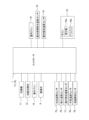
- FIG. 1 is a schematic block diagram of an air conditioner
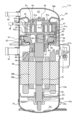
- FIG. It is a schematic cross-sectional block diagram of a compressor.
- 1 is a schematic cross-sectional configuration diagram of an expansion valve
- FIG. 4 is a graph showing the relationship between the discharge gas temperature and the acid value for each air pressure when an acid scavenger is blended at 3 wt %. 4 is a graph showing the relationship between discharge gas temperature and acid value for each air pressure when an acid scavenger is blended at 2 wt %.
- FIG. 10 is a schematic configuration diagram of an air conditioner according to another embodiment J
- FIG. 7 is a schematic cross-sectional configuration diagram of a compressor according to another embodiment J
- FIG. 11 is an enlarged view of the periphery of a floating member of a compressor according to another embodiment J; 10 is a graph showing the relationship between the discharge gas temperature and the acid number when the air pressure is different for the refrigerant circuit according to another embodiment J.
- FIG. 11 is an enlarged view of the periphery of a floating member of a compressor according to another embodiment J; 10 is a graph showing the relationship between the discharge gas temperature and the acid number when the air pressure is different for the refrigerant circuit according to another embodiment J.
- FIG. 1 is a schematic configuration diagram of a refrigerant circuit
- FIG. 2 is a schematic control block configuration diagram.
- the air conditioner 1 is a device that conditions air in a target space by performing a vapor compression refrigeration cycle.
- the air conditioner 1 mainly controls the operation of the outdoor unit 2, the indoor unit 3, the liquid refrigerant communication pipe 6 and the gas refrigerant communication pipe 5 that connect the outdoor unit 2 and the indoor unit 3, and the operation of the air conditioner 1. and a controller 7 .
- the air conditioner 1 performs a refrigeration cycle in which the refrigerant enclosed in the refrigerant circuit 10 is compressed, condensed or released, decompressed, evaporated, and then compressed again.
- the refrigerant circuit 10 is filled with refrigerant for performing a vapor compression refrigeration cycle.
- the refrigerants filled in the refrigerant circuit 10 are a mixed refrigerant containing 1,2-difluoroethylene and one or more hydrofluorocarbons, a mixed refrigerant containing 1,2-difluoroethylene and one or more hydrofluoroolefins, and 1 and/or a mixed refrigerant containing one or more types of hydrofluorocarbons and one or more types of hydrofluoroolefins.
- 1,2-difluoroethylene or other hydrofluoroolefins have a low GWP, which reduces global warming.
- 1,2-difluoroethylene and other hydrofluoroolefins have low stability and are prone to decomposition due to disproportionation reactions and the like.
- the pressure of the air inside the refrigerant circuit 10 is 667 Pa or less, and the refrigerating machine oil contains 3.0% by weight or more and 5.0% by weight or less of the acid scavenger, Since the temperature of the refrigerating machine oil in the oil reservoir, which will be described later, is maintained at 120° C. or lower, deterioration and decomposition of the refrigerant are suppressed.
- the mixed refrigerant containing 1,2-difluoroethylene and one or more hydrofluorocarbons includes, for example, a mixed refrigerant containing 1,2-difluoroethylene and R32, and a mixed refrigerant containing only 1,2-difluoroethylene and R32. , a mixed refrigerant containing 1,2-difluoroethylene, R32 and R1234yf, and a mixed refrigerant containing only 1,2-difluoroethylene, R32 and R1234yf.
- mixed refrigerants containing 1,2-difluoroethylene and one or more hydrofluoroolefins include, for example, mixed refrigerants containing 1,2-difluoroethylene and R1234yf, and mixtures consisting only of 1,2-difluoroethylene and R1234yf.
- Refrigerant, a mixed refrigerant containing 1,2-difluoroethylene, R32 and R1234yf, and a mixed refrigerant containing only 1,2-difluoroethylene, R32 and R1234yf include, for example, mixed refrigerants containing 1,2-difluoroethylene and R1234yf, and mixtures consisting only of 1,2-difluoroethylene and R1234yf.
- mixed refrigerants containing one or more hydrofluorocarbons and one or more hydrofluoroolefins include mixed refrigerants containing R1234yf, R1234ze, R1233zd, and hydrofluorocarbons, and mixed refrigerants containing only R1234yf, R1234ze, R1233zd, and hydrofluorocarbons.
- a mixed refrigerant containing 1,2-difluoroethylene, R32 and R1234yf, and a mixed refrigerant containing only 1,2-difluoroethylene, R32 and R1234yf. is mentioned.
- the hydrofluorocarbons include R32, R134a, R410A, etc. Among them, R32 is preferable.
- the refrigerant circuit 10 is filled with refrigerating machine oil together with the refrigerant.
- Ether oil or ester oil is preferable as the refrigerating machine oil used together with the refrigerant.
- Ether oils include, for example, polyvinyl ether oils (PVE) and polyoxyalkylene oils.
- ester oils include dibasic acid ester oil of dibasic acid and monohydric alcohol, polyol ester oil of polyol and fatty acid, or complex ester of polyol, polybasic acid and monohydric alcohol (or fatty acid). oil, polyol carbonate oil, and the like.
- refrigerating machine oil may be used individually by 1 type, and may be used in combination of 2 or more types.
- an acid scavenger is blended in the refrigerator oil. This suppresses corrosion of the refrigerant circuit 10 due to acid that may be generated by decomposition of the refrigerant.
- the blending amount of the acid scavenger is, for example, a value obtained by measuring the refrigerating machine oil stored in the oil reservoir 37 of the compressor 11 in the refrigerant circuit 10 of the air conditioner 1 whose operation is stopped.
- phenyl glycidyl ether, alkyl glycidyl ether, alkylene glycol glycidyl ether, cyclohexene oxide, ⁇ -olefin oxide, epoxy compounds such as epoxidized soybean oil, carbodiimide, and the like can be used.
- phenyl glycidyl ether, alkyl glycidyl ether, alkylene glycol glycidyl ether, cyclohexene oxide, and ⁇ -olefin oxide are preferred from the viewpoint of compatibility.
- the number of carbon atoms thereof should be 3 or more and 30 or less, and more preferably 4 or more and 24 or less.
- the ⁇ -olefin oxide may have a total carbon number of 4 or more and 50 or less, more preferably 4 or more and 24 or less. Only one type of acid scavenger may be used, or a plurality of types may be used in combination.
- the refrigerator oil can further contain at least one or more selected from the group consisting of extreme pressure agents and antioxidants as additives. These additives are preferably blended in, for example, 3 wt % or less in the refrigerator oil. By adjusting the blending amount of the antioxidant and the acid scavenger, it becomes easier to adjust the water content in the fluid containing the refrigerant and the refrigerating machine oil.
- extreme pressure agents include those containing phosphoric acid esters, monosulfides, polysulfides, sulfoxides, sulfones, thiosulfinates, sulfurized fats and oils, thiocarbonates, thiophenes, thiazoles, methanesulfone
- Organic sulfur compound-based extreme pressure agents such as acid esters, thiophosphate ester-based extreme pressure agents such as thiophosphate triesters, higher fatty acids, hydroxyaryl fatty acids, polyhydric alcohol esters, acrylic acid esters, etc.
- Ester type extreme pressure agents chlorinated hydrocarbons such as chlorinated paraffin, organic chlorine type extreme pressure agents such as chlorinated carboxylic acid derivatives, fluorinated aliphatic carboxylic acids, fluorinated ethylene resins, fluorinated alkyl polysiloxanes organic fluorinated extreme pressure agents such as fluorinated graphite, alcohol extreme pressure agents such as higher alcohols, naphthenates (lead naphthenate, etc.), fatty acid salts (fatty acid lead, etc.), thiophosphates (dialkyl Zinc dithiophosphate, etc.), thiocarbamates, organic molybdenum compounds, organic tin compounds, organic germanium compounds, borate esters, and other metal compound-based extreme pressure agents.
- chlorinated hydrocarbons such as chlorinated paraffin
- organic chlorine type extreme pressure agents such as chlorinated carboxylic acid derivatives, fluorinated aliphatic carboxylic acids, fluorinated ethylene resins, fluorin
- Phenolic antioxidants include 2,6-di-tert-butyl-4-methylphenol (DBPC), 2,6-di-tert-butyl-4-ethylphenol, 2,2′-methylenebis(4 -methyl-6-tert-butylphenol), 2,4-dimethyl-6-tert-butylphenol, 2,6-di-tert-butylphenol, di-tert-butyl-p-cresol, bisphenol A and the like.
- DBPC 2,6-di-tert-butyl-4-methylphenol
- 2,6-di-tert-butyl-4-ethylphenol 2,2′-methylenebis(4 -methyl-6-tert-butylphenol), 2,4-dimethyl-6-tert-butylphenol, 2,6-di-tert-butylphenol, di-tert-butyl-p-cresol, bisphenol A and the like.
- Amine antioxidants include N,N'-diisopropyl-p-phenylenediamine, N,N'-di-sec-butyl-p-phenylenediamine, phenyl- ⁇ -naphthylamine, N.I. N'-di-phenyl-p-phenylenediamine, N,N-di(2-naphthyl)-p-phenylenediamine and the like.
- the moisture content inside the refrigerant circuit 10 is preferably 300 ppm or less.
- the air pressure inside the refrigerant circuit 10 is 667 Pa (5 Torr) or less from the viewpoint of suppressing the decomposition of 1,2-difluoroethylene and other hydrofluoroolefins.
- the moisture content and the air pressure inside the refrigerant circuit 10 are determined by, for example, the heat exchanger functioning as a refrigerant condenser (indoor heat exchange It can be the value for the fluid at the outlet of the heat exchanger 18 or the outdoor heat exchanger 13) or the fluid at the outlet of the high-pressure receiver 8, which will be described later.
- the outdoor unit 2 is connected to the indoor unit 3 via the liquid refrigerant communication pipe 6 and the gas refrigerant communication pipe 5, and constitutes a part of the refrigerant circuit 10. As shown in FIG.
- the outdoor unit 2 mainly includes a compressor 11, a four-way switching valve 12, an outdoor heat exchanger 13, an expansion valve 9, a high pressure receiver 8, a low pressure receiver 14, an outdoor fan 15, and a liquid side closing valve. 17 and a gas side shutoff valve 16 .
- the compressor 11 is a device that compresses the low-pressure refrigerant in the refrigeration cycle to high pressure.
- a rotary type or scroll type compressor in which a compression element is rotationally driven by a compressor motor can be used. Details of the compressor 11 of the present embodiment will be described later.
- the compressor motor is for varying the capacity, and the inverter can control the operating frequency.
- the rotation speed of the compressor 11 is controlled using, for example, a predetermined target evaporation temperature as a target value during cooling operation, and the rotation speed is controlled using a predetermined target condensation temperature as a target value during heating operation.
- the four-way switching valve 12 connects the discharge side of the compressor 11 and the outdoor heat exchanger 13 while connecting the suction side of the compressor 11 and the gas side shutoff valve 16.
- a first connection state see the solid line in FIG. 1
- a second connection that connects the suction side of the compressor 11 and the outdoor heat exchanger 13 while connecting the discharge side of the compressor 11 and the gas side shutoff valve 16.
- the state see dotted line in FIG. 1 can be switched.
- the outdoor heat exchanger 13 is a heat exchanger that functions as a condenser or radiator for high-pressure refrigerant in the refrigeration cycle during cooling operation, and as an evaporator for low-pressure refrigerant in the refrigeration cycle during heating operation.
- the outdoor heat exchanger 13 includes a plurality of heat transfer tubes (not shown) through which refrigerant flows, and a plurality of heat transfer fins (not shown) through which air flows through the gaps between them.
- a plurality of heat transfer tubes are arranged vertically, and each heat transfer tube extends substantially horizontally.
- a plurality of vertically extending heat transfer fins are arranged along the direction in which the heat transfer tubes extend at predetermined intervals.
- a plurality of heat transfer fins and a plurality of heat transfer tubes are combined such that the plurality of heat transfer tubes pass through each heat transfer fin.
- the outdoor fan 15 supplies the outdoor air in the outdoor unit 2 to the outdoor heat exchanger 13, exchanges heat with the refrigerant in the outdoor heat exchanger 13, and then creates an air flow for discharging to the outside of the outdoor unit 2. give rise to The outdoor fan 15 is rotationally driven by an outdoor fan motor.
- the expansion valve 9 is provided between the liquid side end of the outdoor heat exchanger 13 and the high pressure receiver 8 .
- the expansion valve 9 is, for example, an electronic expansion valve whose opening degree can be adjusted by control, and will be described later in detail.
- the high pressure receiver 8 is provided between the expansion valve 9 and the liquid side shutoff valve 17.
- the high-pressure receiver 8 is a refrigerant container capable of storing surplus refrigerant as liquid refrigerant.
- the low-pressure receiver 14 is provided between the suction side of the compressor 11 and one of the connection ports of the four-way switching valve 12, and is a refrigerant container capable of storing excess refrigerant in the refrigerant circuit 10 as liquid refrigerant. be.
- the liquid-side shutoff valve 17 is a manual valve arranged at the connection portion with the liquid refrigerant communication pipe 6 in the outdoor unit 2 .
- the gas side shutoff valve 16 is a manual valve that is arranged in the connection portion between the outdoor unit 2 and the gas refrigerant communication pipe 5 .
- the outdoor unit 2 has an outdoor unit control section 71 that controls the operation of each section that configures the outdoor unit 2 .
- the outdoor unit control section 71 has a microcomputer including a CPU, memory, and the like.
- the outdoor unit control section 71 is connected to the indoor unit control section 72 of each indoor unit 3 via a communication line, and transmits and receives control signals and the like.
- the outdoor unit 2 is provided with a discharge temperature sensor 75, an intake temperature sensor 76, an outdoor heat exchanger temperature sensor 77, an outside air temperature sensor 78, an oil temperature detection sensor 79, and the like. Each of these sensors is electrically connected to the outdoor unit control section 71 and transmits detection signals to the outdoor unit control section 71 .
- a discharge temperature sensor 75 detects the temperature of refrigerant flowing through a discharge pipe 4 d connecting the discharge side of the compressor 11 and one of the connection ports of the four-way switching valve 12 .
- the intake temperature sensor 76 is connected to the intake pipe 4e extending from the low-pressure receiver 14 to the intake side of the compressor 11 in the intake passage connecting the intake side of the compressor 11 and one of the connection ports of the four-way switching valve 12.
- the outdoor heat exchanger temperature sensor 77 detects the temperature of the refrigerant flowing through the liquid-side outlet of the outdoor heat exchanger 13 opposite to the side to which the third pipe 4c is connected.
- the outdoor air temperature sensor 78 detects the outdoor air temperature before passing through the outdoor heat exchanger 13 .
- the oil temperature detection sensor 79 detects the temperature of refrigerating machine oil stored in the oil reservoir 37 of the compressor 11 .
- the indoor unit 3 is installed on an indoor wall surface, ceiling, or the like, which is the target space.
- the indoor unit 3 is connected to the outdoor unit 0 via the liquid refrigerant communication pipe 6 and the gas refrigerant communication pipe 5, and constitutes a part of the refrigerant circuit 10. As shown in FIG.
- the indoor unit 3 has an indoor heat exchanger 18 and an indoor fan 19.
- the indoor heat exchanger 18 has a liquid side connected to the liquid refrigerant communication pipe 6 and a gas side end connected to the gas refrigerant communication pipe 5 .
- the indoor heat exchanger 18 is a heat exchanger that functions as a low-pressure refrigerant evaporator in the refrigeration cycle during cooling operation, and functions as a high-pressure refrigerant condenser or radiator in the refrigeration cycle during heating operation.
- the indoor fan 19 sucks indoor air, which is the space to be air-conditioned, into the indoor unit 3, exchanges heat with the refrigerant in the indoor heat exchanger 18, and then creates an air flow for discharging to the outside of the indoor unit 3. give rise to
- the indoor fan 19 is rotationally driven by an indoor fan motor.
- the indoor unit 3 has an indoor unit control section 72 that controls the operation of each section that configures the indoor unit 3 .
- the indoor unit control section 72 has a microcomputer including a CPU, memory, and the like.
- the indoor unit control section 72 is connected to the outdoor unit control section 71 via a communication line, and transmits and receives control signals and the like.
- the indoor unit 3 is provided with an indoor liquid-side heat exchanger temperature sensor 73, an indoor air temperature sensor 74, and the like. Each of these sensors is electrically connected to the indoor unit controller 72 and transmits detection signals to the indoor unit controller 72 .
- the indoor liquid-side heat exchanger temperature sensor 73 detects the temperature of the refrigerant flowing through the liquid-side outlet of the indoor heat exchanger 18 opposite to the side to which the gas refrigerant communication pipe 5 is connected.
- the indoor air temperature sensor 74 detects the indoor air temperature before passing through the indoor heat exchanger 18 .
- Controller 7 In the air conditioner 1, the controller 7 that controls the operation of the air conditioner 1 is configured by connecting the outdoor unit controller 71 and the indoor unit controller 72 via a communication line.
- the controller 7 mainly has a processor such as a CPU (Central Processing Unit) and memories such as ROM and RAM. Various processes and controls by the controller 7 are realized by integrally functioning each part included in the outdoor unit control section 71 and/or the indoor unit control section 72 .
- a processor such as a CPU (Central Processing Unit)
- memories such as ROM and RAM.
- the controller 7 controls the components of the refrigerant circuit 10 of the air conditioner 1 so that the temperature of the refrigerating machine oil stored in the oil reservoir 37 is maintained at 120°C or less.
- the rotation speed of the compressor 11 is controlled so that the temperature of the refrigerating machine oil detected by the oil temperature detection sensor 79 is maintained at 120° C. or less.
- Remote control 70 The remote controller 70 is placed in a room that is an air-conditioned space or in a specific space of a building that includes the air-conditioned space, and is used by a user or the like to issue operation control commands and monitor the operating state of the air conditioner 1. .
- the remote controller 70 includes a reception unit 70a such as an operation button or a touch panel for receiving input of information by being operated by a user or the like, and a display 70b capable of displaying various information.
- the remote controller 70 is connected to the outdoor unit control section 71 and the indoor unit control section 72 via a communication line, and is capable of supplying the controller 7 with information received by the reception section 70a from the user. .
- Information received from the controller 7 can also be output on the display 70b.
- the information that the reception unit 70a receives from the user or the like is not particularly limited, but includes various information such as a command to execute the cooling operation mode, a command to execute the heating operation mode, a command to stop the operation, and designation of the set temperature.
- the information displayed on the display 70b is not particularly limited, but includes the current operating mode state (cooling or heating), the set temperature, and information indicating that various abnormalities have occurred.
- Compressor 11 for example, a scroll compressor as shown in FIG. 3 can be used.
- the compressor 11 includes a casing 20, a scroll compression mechanism 21, a drive motor 24, a crankshaft 25, a lower bearing 26, and a balance weight 30.
- the casing 20 has a substantially cylindrical member 20a with an upper and lower opening, and an upper lid 20b and a lower lid 20c provided at the upper and lower ends of the cylindrical member 20a, respectively.
- the cylindrical member 20a, the upper lid 20b and the lower lid 20c are fixed by welding so as to maintain airtightness.
- Casing 20 houses the components of compressor 11 , including scroll compression mechanism 21 , drive motor 24 , crankshaft 25 , and lower bearing 26 .
- An oil reservoir 37 is formed between the lower end of the inside of the casing 20 and a predetermined height.
- the oil reservoir 37 has an oil reservoir space So for storing refrigerating machine oil O for lubricating the scroll compression mechanism 21 and the like.
- the oil reservoir 37 is provided with an oil temperature detection sensor 79 for detecting the temperature of the reserved refrigerator oil.
- the oil temperature detection sensor 79 is attached to the outer surface of the lower lid 20c in order to detect the temperature of the refrigerating machine oil stored in the oil reservoir 37.
- a suction pipe 4e for sucking the low-pressure gas refrigerant in the refrigerating cycle of the refrigerant circuit 10 and supplying the gas refrigerant to the scroll compression mechanism 21 is provided through the upper lid 20b.
- a lower end of the intake pipe 4 e is connected to the fixed scroll 22 of the scroll compression mechanism 21 .
- the intake pipe 4e communicates with a compression chamber Sc of a scroll compression mechanism 21, which will be described later.
- An intermediate portion of the cylindrical member 20a of the casing 20 is provided with a discharge pipe 4d through which the refrigerant discharged to the outside of the casing 20 passes.
- the discharge pipe 4 d is arranged such that the end of the discharge pipe 4 d inside the casing 20 protrudes into the high-pressure space Sh formed below the housing 27 of the scroll compression mechanism 21 .
- the high-pressure refrigerant in the refrigeration cycle after being compressed by the scroll compression mechanism 21 flows through the discharge pipe 4d.
- the scroll compression mechanism 21 mainly has a housing 27, a fixed scroll 22 arranged above the housing 27, and a movable scroll 23 combined with the fixed scroll 22 to form a compression chamber Sc.
- the fixed scroll 22 has a flat fixed side end plate 22a, a spiral fixed side wrap 22b protruding from the front surface of the fixed side end plate 22a, and an outer edge portion 22c surrounding the fixed side wrap 22b.
- a non-circular discharge port 22d communicating with the compression chamber Sc of the scroll compression mechanism 21 is formed in the central portion of the fixed side end plate 22a so as to pass through the fixed side end plate 22a in the thickness direction.
- the refrigerant compressed in the compression chamber Sc is discharged from the discharge port 22d, passes through a refrigerant passage (not shown) formed in the fixed scroll 22 and the housing 27, and flows into the high pressure space Sh.
- the compressor 11 is a high-pressure dome-type compressor in which a high-pressure refrigerant exists in a region outside the scroll compression mechanism 21 in the casing 20 .
- the movable scroll 23 includes a flat plate-shaped movable side plate 23a, a spiral movable side wrap 23b protruding from the front surface of the movable side end plate 23a, and a cylindrical boss portion protruding from the rear surface of the movable side end plate 23a. 23c.
- the fixed-side wrap 22b of the fixed scroll 22 and the movable-side wrap 23b of the orbiting scroll 23 are combined in such a manner that the lower surface of the fixed-side end plate 22a and the upper surface of the movable-side end plate 23a face each other.
- a compression chamber Sc is formed between the adjacent fixed side wrap 22b and movable side wrap 23b.
- the boss portion 23c is a cylindrical portion whose upper end is closed.
- the movable scroll 23 and the crankshaft 25 are connected by inserting an eccentric portion 25b of the crankshaft 25, which will be described later, into the hollow portion of the boss portion 23c.
- the boss portion 23 c is arranged in an eccentric space 28 formed between the movable scroll 23 and the housing 27 .
- the eccentric space 28 communicates with the high-pressure space Sh via an oil supply path 39 of the crankshaft 25 (to be described later) and the like, and high pressure acts on the eccentric space 28 .
- This pressure pushes the lower surface of the movable end plate 23 a in the eccentric space 28 upward toward the fixed scroll 22 .
- This force brings the movable scroll 23 into close contact with the fixed scroll 22 .
- the movable scroll 23 is supported by the housing 27 via the Oldham ring 29 arranged in the "Oldham ring space Sr".
- the Oldham ring 29 is a member that prevents the orbiting scroll 23 from rotating and makes it revolve.
- the housing 27 is press-fitted inside the cylindrical member 20a and fixed to the cylindrical member 20a along the entire circumferential direction on its outer peripheral surface. Further, the housing 27 and the fixed scroll 22 are fixed by bolts (not shown) or the like so that the upper end surface of the housing 27 is in close contact with the lower surface of the outer edge portion 22c of the fixed scroll 22 .
- the housing 27 is formed with a recess 27a that is recessed in the center of the upper surface, and an upper bearing portion 27b that is located below the recess 27a.
- the concave portion 27a surrounds the side surface of the eccentric space 28 in which the boss portion 23c of the orbiting scroll 23 is arranged.
- An upper bearing 35 which is a cylindrical metal member that supports the main shaft 25a of the crankshaft 25, is arranged in the upper bearing portion 27b.
- the upper bearing 35 rotatably supports the main shaft 25a inserted into the upper bearing 35 .
- an Oldham ring space Sr in which the Oldham ring 29 is arranged is formed in the housing 27 .
- the drive motor 24 has an annular stator 33 fixed to the inner wall surface of the cylindrical member 20a, and a rotor 32 rotatably accommodated inside the stator 33 with a small gap (air gap passage).
- the stator 33 is configured with a coil.
- the rotor 32 is connected to the orbiting scroll 23 via a crankshaft 25 arranged to extend vertically along the axis of the cylindrical member 20a. Rotation of the rotor 32 causes the movable scroll 23 to revolve with respect to the fixed scroll 22 .
- the crankshaft 25 transmits the driving force of the drive motor 24 to the movable scroll 23 .
- the crankshaft 25 is arranged to extend vertically along the axis of the cylindrical member 20 a and connects the rotor 32 of the drive motor 24 and the orbiting scroll 23 of the scroll compression mechanism 21 .
- the crankshaft 25 has a main shaft 25a whose center axis coincides with the axis of the cylindrical member 20a, and an eccentric portion 25b that is eccentric with respect to the axis of the cylindrical member 20a.
- the eccentric portion 25b is inserted into the boss portion 23c of the movable scroll 23 as described above.
- a pin bearing 31, which is a cylindrical metal member that pivotally supports the eccentric portion 25b, is provided on the radially outer side of the eccentric portion 25b.
- the main shaft 25a is rotatably supported by a pin bearing 31, an upper bearing 35 of an upper bearing portion 27b of the housing 27, and a lower bearing 26, which will be described later.
- the main shaft 25 a is connected to the rotor 32 of the drive motor 24 between the upper bearing 35 and the lower bearing 26 .
- An oil supply path 39 for supplying refrigerating machine oil O to the scroll compression mechanism 21 and the like is formed inside the crankshaft 25 .
- the lower end of the main shaft 25a is positioned within the oil pool space So of the oil pool portion 37 formed in the lower portion of the casing 20, and the refrigerating machine oil O in the oil pool space So is supplied to the scroll compression mechanism 21 and the like through the oil supply path 39. be.
- the balance weight 30 is a member separate from the crankshaft 25, has an annular shape, and is fitted to the main shaft 25a.
- the balance weight 30 has a cylindrical portion 30a and an eccentric portion 30b formed in a part of the cylindrical portion 30a in the circumferential direction.
- the center of gravity of the cylindrical portion 30a is on the axis of the crankshaft 25, and has a circular shape when viewed in the axial direction.
- the center of gravity of the eccentric portion 30b is eccentric from the axial center of the crankshaft 25, specifically, eccentric from the axial center of the crankshaft 25 in a predetermined direction.
- the center of gravity of the entire balance weight 30 is also eccentric from the axial center of the crankshaft 25 in a predetermined direction.
- the movable scroll 23 is slidably supported by the eccentric portion 25b of the crankshaft 25 near its center. Thereby, the movable scroll 23 is also eccentric in the same direction as the eccentric portion 25b.
- the lower bearing 26 is arranged below the drive motor 24 .
- the lower bearing 26 is fixed inside and below the cylindrical member 20a.
- the lower bearing 26 constitutes a bearing on the lower end side of the crankshaft 25 and is a cylindrical metal member that supports the main shaft 25a of the crankshaft 25 so as to be rotatable.
- the refrigerant in the compression chamber Sc is compressed as the volume of the compression chamber Sc decreases, and finally becomes a high-pressure gas refrigerant.
- a high-pressure gas refrigerant is discharged from a discharge port 22d located near the center of the stationary end plate 22a. After that, the high pressure gas refrigerant passes through a refrigerant passage (not shown) formed in the fixed scroll 22 and the housing 27 and flows into the high pressure space Sh.
- the high-pressure gas refrigerant in the refrigeration cycle after being compressed by the scroll compression mechanism 21, which has flowed into the high-pressure space Sh, is discharged from the discharge pipe 4d.
- the expansion valve 9 mainly has a coil 91, a rotor 92, a valve body 93, a casing 94, a valve seat member 95 and the like.
- the coil 91 is provided in the circumferential direction when the longitudinal direction of the valve body 93 is taken as the axial direction.
- the rotor 92 is rotationally driven by the coil 91 .
- the rotor 92 moves in the direction of the screw axis by rotating.
- the valve body 93 is composed of a shaft 93a and a needle 93b.
- the shaft 93a has a cylindrical shape and extends vertically.
- One end of the shaft 93a is attached coaxially to the rotor 92, and moves axially together with the rotor 92.
- the needle 93b is provided in a conical shape facing downward at the lower end of the shaft 93a.
- the needle 93b protrudes into a valve-body-side space 96, which will be described later.
- the casing 94 accommodates the coil 91, the rotor 92, the shaft 93a of the valve body 93, etc. inside.
- the valve seat member 95 is provided below the casing 94 .
- the valve seat member 95 includes a first connecting portion 97, a second connecting portion 98, a valve body side space 96 for allowing communication between the first connecting portion 97 and the second connecting portion 98, and a first connection between the valve body side space 96 and the valve body side space 96. and a valve seat 99 provided between the portion 97 and the valve seat 99 .
- the valve seat 99 is formed in a funnel shape so as to face the needle 93b of the valve body 93 from below in the radial direction outside.
- the high-pressure liquid refrigerant that has flowed in from the first connecting portion 97 or the second connecting portion 98 is decompressed by passing through the gap between the needle 93b and the valve seat 99.
- the degree of pressure reduction at that time is adjusted by rotating the rotor 92 to advance and retract the valve body 93 to change the size of the gap between the needle 93b and the valve seat 99.
- the valve body 93 having the needle 93b can be made of SUS or brass, for example.
- the SUS valve body 93 is made of stainless steel such as SUS304, which has a chromium content of 10.5% by mass or more and a carbon content of 1.2% by mass or less. mentioned.
- a copper alloy containing 20% by mass or more of zinc can be used as the valve body 93 made of brass. Even if the valve body 93 having the needle 93b is made of such material, in the air conditioner 1 of the present embodiment, the air pressure inside the refrigerant circuit 10 is 667 Pa or less, and the refrigerating machine oil is 3.0 Pa or less.
- the acid scavenger is contained in an amount of not less than 5.0% by weight and not more than 5.0% by weight, the temperature of the refrigerating machine oil in the oil reservoir 37 is maintained at 120° C. or less. Corrosion of 93 is suppressed.
- 1,2-difluoroethylene and other hydrofluoroolefins used as refrigerants are unstable and prone to decomposition.
- a mixture containing 1,2-difluoroethylene and one or more hydrofluorocarbons A mixed refrigerant of either a refrigerant, a mixed refrigerant containing 1,2-difluoroethylene and one or more hydrofluoroolefins, or a mixed refrigerant containing one or more hydrofluorocarbons and one or more hydrofluoroolefins I am using This makes it possible to suppress the disproportionation reaction of 1,2-difluoroethylene and other hydrofluoroolefins.
- 1,2-difluoroethylene and other hydrofluoroolefins are likely to decompose in a high-temperature environment, especially in the refrigerant circuit where they are present together with high-temperature refrigerating machine oil.
- an acid such as hydrofluoric acid is generated from refrigerant deterioration products generated by such thermal decomposition of the refrigerant, which may corrode constituent elements of the refrigerant circuit.
- the pressure of the air inside the refrigerant circuit 10 is set to 667 Pa or less, and 3.0% by weight or more and 5.0% by weight or less of the acid scavenger is added to the refrigerating machine oil.
- the temperature of the refrigerating machine oil in the oil reservoir 37 is maintained at 120° C. or lower. This sufficiently suppresses the decomposition of the refrigerant that exists together with the refrigerating machine oil, suppresses the generation of acids such as hydrofluoric acid from the decomposition products, and suppresses the corrosion of the components of the refrigerant circuit 10 .
- the temperature of the refrigerating machine oil in the oil reservoir 37 can be raised to 120° C., so the operating condition range can be widened.
- FIG. 5 shows the refrigerant circuit 10 provided in the air conditioner 1 of the present embodiment.
- 3 shows the relationship between the discharged gas temperature and the acid value.
- a mixed refrigerant of 1,2-difluoroethylene and HFO-1234yf (weight ratio is 40 parts by mass: 60 parts by mass) is used as the refrigerant, and 3.0% by weight of an epoxy acid scavenger is blended as the acid scavenger.
- PVE refrigerating machine oil
- the acid value is the number of milligrams (mg) of potassium hydroxide (KOH) required to neutralize the acidic component contained in 1 g of the sample.
- Refrigerant oil was blended with 2.0% by weight of an acid scavenger, and while other conditions were the same as those for the measurement shown in FIG. Figure 6 shows the relationship between Here, a refrigerating machine oil (PVE) containing 2.0% by weight of an epoxy-based acid scavenger was used as the acid scavenger.
- PVE refrigerating machine oil
- the air pressure in the refrigerant circuit 10 is 667 Pa or less, and the discharge gas temperature of the compressor 11 is maintained at 120° C. or less. 0.10 (mgKOH/g) or less, and it can be seen that the corrosion of the components of the refrigerant circuit 10 is suppressed.
- the refrigerating machine oil stored in the oil reservoir 37 is located on the high pressure side of the compression mechanism 21 of the compressor 11, and high pressure acts thereon. It corresponds to the temperature detected by the detection sensor 79 .
- Embodiments (5-1) Other Embodiments A
- the air pressure inside the refrigerant circuit 10 is 667 Pa or less
- the refrigerating machine oil contains 3.0% by weight or more and 5.0% by weight or less of the acid scavenger
- the oil reservoir portion 37 The air conditioner 1 in which the temperature of the refrigerating machine oil is maintained at 120° C. or less has been described as an example.
- the air conditioner 1 is not limited to this. Alternatively, it may be an air conditioner that contains less than 3.0% by weight of an acid scavenger and maintains the temperature of the refrigerating machine oil in the oil reservoir 37 at 100° C. or lower, and may be maintained at 900° C. or lower. It may be an air conditioner. In this case, the refrigerating machine oil may contain the acid scavenger in an amount of 1.0% by weight or more and 2.5% by weight or less, or may be contained in an amount of 2.0% by weight.
- the decomposition of the refrigerant is suppressed and the corrosion of the components of the refrigerant circuit 10 due to decomposition products is suppressed by maintaining the temperature at a low temperature or lower, more preferably at a temperature lower than about 30 degrees. Further, according to FIGS. 5 and 6, even when the pressure of the air inside the refrigerant circuit 10 increases by about 667 Pa, the upper limit temperature of the refrigerating machine oil in the oil reservoir 37 is about 20° C. lower or lower. It can be seen that the decomposition of the refrigerant is suppressed and the corrosion of the constituent elements of the refrigerant circuit 10 due to the decomposed products is suppressed by maintaining such a value.
- the pressure of the air inside the refrigerant circuit 10 is 2000 Pa or less, and the refrigerating machine oil contains 3.0% by weight or more and 5.0% by weight or less of an acid scavenger.
- the temperature of the refrigerating machine oil in the oil reservoir 37 may be maintained at 100° C. or less.
- the pressure of the air inside the refrigerant circuit 10 is 2000 a or less, and the refrigerating machine oil does not contain an acid scavenger, or the acid scavenger is less than 3.0% by weight.
- It may be an air conditioner in which the temperature of the refrigerating machine oil in the oil reservoir 37 is maintained at 80° C. or lower.
- the refrigerating machine oil may contain 1.0% by weight or more and 2.5% by weight or less of the acid scavenger.
- the decomposition of the refrigerant is suppressed and the corrosion of the components of the refrigerant circuit 10 due to decomposition products is suppressed by maintaining the temperature at a low temperature or lower, more preferably at a temperature lower than about 30 degrees.
- the upper limit temperature of the refrigerating machine oil in the oil reservoir portion 37 is about 20° C. lower or lower. It can be seen that the decomposition of the refrigerant is suppressed and the corrosion of the constituent elements of the refrigerant circuit 10 due to the decomposed products is suppressed by maintaining such a value. From these, it can be seen that if the air pressure inside the refrigerant circuit 10 is 2000a or less, the air conditioner can maintain the temperature of the refrigerating machine oil in the oil reservoir 37 at 80° C. or less.
- the pressure of the air inside the refrigerant circuit 10 is 4000 Pa or less, and the refrigerating machine oil contains 3.0% by weight or more and 5.0% by weight or less of an acid scavenger.
- the temperature of the refrigerating machine oil in the oil reservoir 37 may be maintained at 80° C. or lower.
- the predetermined upper limit temperature of the refrigerating machine oil stored in the oil reservoir 37 may be determined based on the air pressure inside the refrigerant circuit 10 .
- the temperature of the refrigerating machine oil obtained by substituting the value of the air pressure inside the refrigerant circuit 10 into the following equation may be used as the upper limit temperature.
- the following equations are obtained based on experimental results showing how the refrigerant is decomposed according to the temperature of the refrigerating machine oil and the pressure of the air inside the refrigerant circuit 10 .
- the pressure of the air inside the refrigerant circuit 10 is 667 Pa or less
- the refrigerating machine oil contains 2.0% by weight or more of the acid scavenger
- the refrigeration in the oil reservoir 37 is It may be an air conditioner in which the temperature of machine oil is maintained at 120° C. or lower.
- the pressure of the air inside the refrigerant circuit 10 is 667 Pa or less
- the refrigerating machine oil contains 0.3% by weight or more of the acid scavenger
- the refrigeration in the oil reservoir 37 is It may be an air conditioner in which the temperature of machine oil is maintained at 100° C. or less.
- the pressure of the air inside the refrigerant circuit 10 is 1333 Pa or less
- the refrigerating machine oil contains 0.3% by weight or more of the acid scavenger
- the refrigeration in the oil reservoir 37 is It may be an air conditioner in which the temperature of machine oil is maintained at 80° C. or lower.
- the correlation between the rotation speed of the compressor 11 and the temperature of the refrigerating machine oil in the oil sump 37 is stored as data in a memory, and the temperature of the refrigerating machine oil in the oil sump 37 is determined based on the data.
- the number of rotations may be controlled so that the temperature is maintained below a predetermined value.
- the correlation between the discharge temperature, which is the temperature of the refrigerant discharged from the compressor 11, and the temperature of the refrigerating machine oil in the oil sump 37 is stored as data in a memory, and based on the data, the oil sump is The discharge temperature may be controlled so that the temperature of the refrigerating machine oil 37 is maintained below a predetermined value.
- the correlation between the discharge pressure, which is the pressure of the refrigerant discharged from the compressor 11, and the temperature of the refrigerating machine oil in the oil reservoir 37 is stored as data in a memory, and based on the data, the oil reservoir The discharge pressure may be controlled so that the temperature of the refrigerating machine oil 37 is maintained below a predetermined value.
- the air conditioner 1 may have a refrigerant circuit 10 using a low-pressure dome-shaped compressor 11a.
- the refrigerant and refrigerating machine oil to be used are the same as in the above embodiment.
- An air conditioner 1 according to another embodiment J has a refrigerant circuit 10 shown in FIG.
- the same reference numerals are assigned to the same parts as in the above embodiment, and the description thereof is omitted.
- This refrigerant circuit 10 has a first expansion valve 9a and a second expansion valve 9b instead of the expansion valve 9 of the above embodiment, and an injection pipe 4f.
- the first expansion valve 9 a is provided between the high pressure receiver 8 and the outdoor heat exchanger 13 .
- the second expansion valve 9b is provided between the high pressure receiver 8 and the liquid side shutoff valve 17.
- the injection pipe 4f connects the high pressure receiver 8 and the compressor 11a. Details of the compressor 11a will be described below.
- the compressor 11a is a so-called low-pressure dome scroll compressor. As shown in FIG. 8, the compressor 11a mainly includes a casing 54, a compression mechanism 40, a floating member 47, a housing 52, a seal member 55, a motor 58, a crankshaft 59, and a lower bearing housing. 62.
- the casing 54 has a substantially cylindrical cylindrical member 54a, an upper lid 54b attached to the upper end of the cylindrical member 54a, and a lower lid 54c attached to the lower end of the cylindrical member 54a.
- the cylindrical member 54a, the upper lid 54b and the lower lid 54c are fixed by welding so as to maintain airtightness.
- Casing 54 houses the components of compressor 11 a including compression mechanism 40 , floating member 47 , housing 52 , seal member 55 , motor 58 , crankshaft 59 and lower bearing housing 62 .
- a compression mechanism 40 is installed on the top of the casing 54 .
- a floating member 47 and a housing 52 are installed below the compression mechanism 40 .
- a motor 58 is installed below the housing 52 .
- a lower bearing housing 62 is installed below the motor 58 .
- An oil reservoir 37a is formed at the bottom of the casing 54.
- the oil reservoir portion 37a has an oil reservoir space So in which refrigerating machine oil for lubricating the compression mechanism 40 and the like is stored.
- the oil reservoir portion 37a is a portion of the casing 54 and corresponds to a portion below the lower bearing housing 62. As shown in FIG.
- the oil reservoir 37a is composed of a lower lid 54c and a lower end of a cylindrical member 54a.
- An oil temperature detection sensor 79 is attached to the outer surface of the oil reservoir 37a. The oil temperature detection sensor 79 measures the temperature of the refrigerating machine oil stored in the oil reservoir 37a.
- the internal space of the casing 54 is partitioned into a first space S1 and a second space S2 by a first flow path 56.
- the first space S ⁇ b>1 is a space below the first flow path 56 .
- the second space S ⁇ b>2 is a space above the first flow path 56 .
- the first flow path 56 is fixed by welding to the compression mechanism 40 and the casing 54 so as to keep airtightness between the first space S1 and the second space S2.
- the first flow path 56 is a plate-like member that is annular in plan view.
- the inner peripheral side of the first flow path 56 is fixed to the upper portion of the fixed scroll 41 of the compression mechanism 40 over the entire circumference.
- the outer peripheral side of the first flow path 56 is fixed to the inner surface of the casing 54 over the entire circumference.
- the first space S1 is a space in which the motor 58 is installed.
- the first space S1 is a space into which refrigerant before being compressed by the compressor 11a flows from the refrigerant circuit 10 having the compressor 11a.
- the first space S1 is a space into which a low-pressure refrigerant in the refrigeration cycle flows.
- the second space S2 is a space into which refrigerant discharged from the compression mechanism 40 (refrigerant compressed by the compression mechanism 40) flows.
- the second space S2 is a space into which high-pressure refrigerant in the refrigeration cycle flows.
- a suction pipe 4e, a discharge pipe 4d, and an injection pipe 4f are attached to the casing 54 so that the inside and outside of the casing 54 are communicated.
- the suction pipe 4e is attached near the center of the casing 54 in the vertical direction (vertical direction). Specifically, as shown in FIG. 8, the suction pipe 4e is horizontally attached to the cylindrical member 54a at a height position between the housing 52 and the motor 58. As shown in FIG. The suction pipe 4 e communicates the outside of the casing 54 with the first space S ⁇ b>1 inside the casing 54 . Refrigerant before compression (low-pressure refrigerant in the refrigeration cycle) flows through the suction pipe 4e into the first space S1.
- the discharge pipe 4 d is attached to the upper portion of the casing 54 at a height position above the first flow path 56 .
- the suction pipe 4e is horizontally attached to the upper lid 54b.
- the discharge pipe 4 d communicates the outside of the casing 54 with the second space S ⁇ b>2 inside the casing 54 .
- the refrigerant compressed by the compression mechanism 40 and flowed into the second space S2 flows out of the compressor 11a through the discharge pipe 4d.
- the injection pipe 4f is attached to the upper portion of the casing 54 at a height position below the first flow path 56. Specifically, as shown in FIG. 8, the injection pipe 4f is horizontally attached to the cylindrical member 54a at a height position of the compression mechanism 40. As shown in FIG. The end of the injection pipe 4f on the inner side of the casing 54 is connected to the fixed scroll 41 of the compression mechanism 40, as shown in FIG. The injection pipe 4f communicates with the compression chamber Sc inside the compression mechanism 40 during compression via a passage (not shown) formed in the fixed scroll 41 .
- An intermediate pressure refrigerant (an intermediate pressure refrigerant between low pressure and high pressure in the refrigeration cycle) is supplied from the refrigerant circuit 10 having the compressor 11a to the compression chamber Sc during compression through the injection pipe 4f.
- the compression mechanism 40 mainly has a fixed scroll 41 and a movable scroll 42 .
- the fixed scroll 41 and the movable scroll 42 are combined with each other to form a compression chamber Sc.
- the compression mechanism 40 compresses the refrigerant in the compression chamber Sc and discharges the compressed refrigerant.
- the fixed scroll 41 is mounted on the housing 52 as shown in FIG.
- the fixed scroll 41 and the housing 52 are fixed to each other by fixing means such as bolts.
- the fixed scroll 41 has a disk-shaped fixed-side end plate 41a, a spiral fixed-side wrap 41b, and a peripheral edge portion 41c.
- the fixed-side wrap 41b and the peripheral portion 41c extend from the front surface (lower surface) of the fixed-side end plate 41a toward the movable scroll 42 (downward).
- the fixed side wrap 41b is formed in a spiral shape (involute shape) from the vicinity of the center of the fixed side end plate 41a toward the outer peripheral side.
- the peripheral portion 41c has a cylindrical shape.
- the peripheral edge portion 41c is positioned on the outer peripheral side of the stationary side end plate 41a so as to surround the stationary side wrap 41b.
- the orbiting scroll 42 rotates with respect to the fixed scroll 41, so that the refrigerant (low-pressure refrigerant in the refrigerating cycle) that has flowed from the first space S1 into the compression chamber Sc on the peripheral edge side moves to the innermost side. It is compressed as it moves to the (central side) compression chamber Sc.
- a discharge port 41d for discharging the refrigerant compressed in the compression chamber Sc is formed near the center of the fixed side end plate 41a so as to penetrate the fixed side end plate 41a in its thickness direction (vertical direction).
- the discharge port 41d communicates with the innermost compression chamber Sc.
- a discharge valve 43 for opening and closing the discharge port 41d is attached above the fixed side end plate 41a.
- the discharge valve 43 When the pressure in the innermost compression chamber Sc communicating with the discharge port 41d becomes greater than the pressure in the space above the discharge valve 43 (the second space S2) by a predetermined value or more, the discharge valve 43 is opened to open the discharge port. The coolant flows into the second space S2 from 41d.
- a relief hole 41e is formed through the fixed side panel 41a in the thickness direction on the outer peripheral side of the discharge port 41d of the fixed side panel 41a.
- the relief hole 41e communicates with a compression chamber Sc formed outside the innermost compression chamber Sc communicating with the discharge port 41d.
- the relief hole 41e communicates with the compression chamber Sc in which the compression mechanism 40 is in the middle of compression.
- a plurality of relief holes 41e may be formed in the fixed end plate 41a.
- a relief valve 44 for opening and closing the relief hole 41e is attached above the fixed side end plate 41a.
- the relief valve 44 which is a safety valve, opens and the relief hole 41e opens.
- the coolant flows into the second space S2 from 41e.
- the movable scroll 42 has a disk-shaped movable side end plate 42a, a spiral movable side wrap 42b, and a cylindrical boss portion 42c.
- the movable wrap 42b extends from the front surface (upper surface) of the movable end plate 42a toward the fixed scroll 41 (upward).
- the boss portion 42c extends from the rear surface (lower surface) of the movable end plate 42a toward the motor 58 (downward).
- the orbiting side wrap 42b is formed in a spiral shape (involute shape) from the vicinity of the center of the orbiting side end plate 42a toward the outer peripheral side.
- the fixed side wrap 41b of the fixed scroll 41 and the movable side wrap 42b of the movable scroll 42 are combined with each other to form a compression chamber Sc.
- the fixed scroll 41 and the movable scroll 42 are combined so that the front surface (lower surface) of the fixed side end plate 41a and the front surface (upper surface) of the movable side end plate 42a face each other.
- a compression chamber Sc surrounded by the fixed side end plate 41a, the fixed side wrap 41b, the movable side wrap 42b and the movable side end plate 42a is formed.
- the compression mechanism 40 has a symmetrical wrap structure or an asymmetrical wrap structure.
- a first compression chamber surrounded by the outer peripheral surface of the movable side wrap 42b and the inner peripheral surface of the fixed side wrap 41b, the inner peripheral surface of the movable side wrap 42b and the fixed side wrap 41b. and a second compression chamber surrounded by the outer peripheral surface of the second compression chamber are formed point-symmetrically when viewed in the vertical direction.
- the first compression chamber and the second compression chamber are not formed point-symmetrically when viewed along the vertical direction.
- the movable end plate 42 a is arranged above the floating member 47 .
- the floating member 47 is pushed toward the orbiting scroll 42 by the pressure in the back pressure space Sb formed below the floating member 47 .
- the floating member 47 presses the movable scroll 42 toward the fixed scroll 41 when the upper pressing portion 50 of the floating member 47 contacts the rear surface (lower surface) of the movable end plate 42 a.
- the force of the floating member 47 pressing the orbiting scroll 42 toward the fixed scroll 41 brings the orbiting scroll 42 into close contact with the fixed scroll 41 .
- the back pressure space Sb is a space formed between the floating member 47 and the housing 52 .
- the back pressure space Sb is mainly formed on the back side (lower side) of the floating member 47, as shown in FIG.
- the refrigerant in the compression chamber Sc of the compression mechanism 40 is introduced into the back pressure space Sb.
- a seal is provided between the back pressure space Sb and the first space S1 around the back pressure space Sb.
- the pressure in the back pressure space Sb is higher than the pressure in the first space S1.
- An Oldham coupling 45 is arranged between the movable scroll 42 and the floating member 47 .
- Oldham coupling 45 is slidably engaged with both movable scroll 42 and floating member 47 .
- the Oldham coupling 45 rotates the movable scroll 42 with respect to the fixed scroll 41 while suppressing rotation of the movable scroll 42 .
- the boss portion 42 c is arranged in an eccentric space 51 surrounded by the inner surface of the floating member 47 .
- a first bearing metal 46 is arranged inside the boss portion 42c.
- the first bearing metal 46 is, for example, press-fitted and fixed inside the boss portion 42c.
- An eccentric portion 60 of the crankshaft 59 is inserted into the first bearing metal 46 .
- the movable scroll 42 and the crankshaft 59 are connected by inserting the eccentric portion 60 into the first bearing metal 46 .
- the floating member 47 is arranged on the back side of the movable scroll 42 (the side opposite to the side where the fixed scroll 41 is arranged).
- the floating member 47 presses the movable scroll 42 toward the fixed scroll 41 by being pushed toward the movable scroll 42 by the pressure of the back pressure space Sb.
- a part of the floating member 47 also functions as a bearing that supports the crankshaft 59 .
- the floating member 47 mainly has a cylindrical body portion 47a, a pressing portion 50, and an upper bearing housing 48.
- the body portion 47a forms an eccentric space 51 surrounded by the inner surface of the body portion 47a.
- a boss portion 42 c of the movable scroll 42 is arranged in the eccentric space 51 .
- the pressing portion 50 is a cylindrical member extending from the upper end of the main body portion 47a toward the movable scroll 42. As shown in FIG. 9, the thrust surface 50a at the upper end of the pressing portion 50 faces the rear surface of the movable end plate 42a of the movable scroll 42. As shown in FIG. The thrust surface 50a is formed in an annular shape in plan view. When the floating member 47 is pushed toward the movable scroll 42 by the pressure in the back pressure space Sb, the thrust surface 50a contacts the rear surface of the movable end plate 42a and presses the movable scroll 42 toward the fixed scroll 41.
- the upper bearing housing 48 is a cylindrical member arranged below the body portion 47a (below the eccentric portion space 51).
- a second bearing metal 49 is arranged inside the upper bearing housing 48 .
- the second bearing metal 49 is press-fitted and fixed inside the upper bearing housing 48, for example.
- the second bearing metal 49 rotatably supports the main shaft 61 of the crankshaft 59 .
- the housing 52 is a substantially cylindrical member arranged below the fixed scroll 41 and the floating member 47 .
- Housing 52 supports floating member 47 .
- a back pressure space Sb is formed between the housing 52 and the floating member 47 .
- Housing 52 is attached to the inner surface of casing 54 by, for example, a press fit.
- the sealing member 55 is a member for forming a back pressure space Sb between the floating member 47 and the housing 52 .
- the sealing member 55 is, for example, a gasket such as an O-ring.
- the sealing member 55 partitions the back pressure space Sb into a first chamber B1 and a second chamber B2.
- the first chamber B1 and the second chamber B2 are spaces that are formed in a substantially annular shape in plan view.
- the second chamber B2 is arranged inside the first chamber B1. In plan view, the area of the first chamber B1 is larger than the area of the second chamber B2.
- the first chamber B1 communicates with the compression chamber Sc during compression via the first flow path 56.
- the first flow path 56 is a flow path that guides the refrigerant being compressed in the compression mechanism 40 (intermediate pressure refrigerant) to the first chamber B1.
- a first flow path 56 is formed in the fixed scroll 41 and the housing 52 .
- the second chamber B2 communicates with the discharge port 41d of the fixed scroll 41 via the second flow path 57.
- the second flow path 57 is a flow path that guides the refrigerant (high-pressure refrigerant) discharged from the compression mechanism 40 to the second chamber B2.
- a second flow path 57 is formed in the fixed scroll 41 and the housing 52 .
- the pressure in the second chamber B2 is higher than the pressure in the first chamber B1.
- the area of the first chamber B1 is larger than the area of the second chamber B2 in plan view, it is difficult for the movable scroll 42 to press the fixed scroll 41 excessively due to the pressure in the back pressure space Sb.
- the second chamber B2 is arranged inside the first chamber B1, the pressure of the compression chamber Sc pushes the orbiting scroll 42 downward, and the floating member 47 pushes the orbiting scroll 42 upward. It is easy to ensure a balance between
- the motor 58 drives the movable scroll 42.
- the motor 58 has a stator 58a and a rotor 58b.
- the stator 58 a is an annular member fixed to the inner surface of the casing 54 .
- the rotor 58b is a cylindrical member arranged inside the stator 58a.
- a slight gap (air gap) is formed between the inner peripheral surface of the stator 58a and the outer peripheral surface of the rotor 58b.
- a crankshaft 59 passes through the rotor 58b along its axial direction.
- the rotor 58b is connected to the movable scroll 42 via the crankshaft 59.
- the motor 58 drives the orbiting scroll 42 by rotating the rotor 58 b to orbit the orbiting scroll 42 with respect to the fixed scroll 41 .
- the crankshaft 59 connects the rotor 58b of the motor 58 and the movable scroll 42 of the compression mechanism 40 .
- the crankshaft 59 extends vertically.
- the crankshaft 59 transmits the driving force of the motor 58 to the movable scroll 42 .
- the crankshaft 59 mainly has an eccentric portion 60 and a main shaft 61 .
- the eccentric part 60 is arranged above the main shaft 61 .
- the central axis of the eccentric portion 60 is eccentric with respect to the central axis of the main shaft 61 .
- the eccentric portion 60 is connected to the first bearing metal 46 arranged inside the boss portion 42 c of the movable scroll 42 .
- the main shaft 61 is rotatably supported by the second bearing metal 49 arranged in the upper bearing housing 48 of the floating member 47 and the third bearing metal 63 arranged in the lower bearing housing 62 .
- Main shaft 61 is coupled to rotor 58 b of motor 58 between upper bearing housing 48 and lower bearing housing 62 .
- the main shaft 61 extends vertically.
- An oil passage (not shown) is formed inside the crankshaft 59 .
- the oil passage has a main route and a branch route.
- the main path extends in the axial direction of crankshaft 59 from the lower end to the upper end of crankshaft 59 .
- the branch path extends radially of the crankshaft 59 from the main path.
- the refrigerating machine oil in the oil reservoir 37a is pumped up by a pump (not shown) provided at the lower end of the crankshaft 59, passes through an oil path, and flows through the crankshaft 59, the first bearing metal 46, and the second bearing metal 49. and the third bearing metal 63, the sliding portion of the compression mechanism 40, and the like.
- the lower bearing housing 62 is fixed to the inner surface of the casing 54.
- a lower bearing housing 62 is positioned below the motor 58 .
- a third bearing metal 63 is arranged inside the lower bearing housing 62 .
- the third bearing metal 63 is press-fitted and fixed inside the lower bearing housing 62, for example.
- the main shaft 61 of the crankshaft 59 passes through the third bearing metal 63 .
- the third bearing metal 63 rotatably supports the lower side of the main shaft 61 of the crankshaft 59 .
- the normal state is a state in which the pressure of the refrigerant discharged from the discharge port 41d of the compression mechanism 40 is higher than the pressure in the compression chamber Sc during compression.
- An intermediate-pressure refrigerant is injected from the injection pipe 4f into the compression chamber Sc during compression.
- the pressure of the refrigerant rises as it moves from the compression chamber Sc on the peripheral side (outside) to the compression chamber Sc on the center side (inner side), and finally reaches a high pressure in the refrigeration cycle.
- the refrigerant compressed by the compression mechanism 40 is discharged to the second space S2 from the discharge port 41d of the fixed end plate 41a.
- the high-pressure refrigerant in the second space S2 is discharged from the discharge pipe 4d.
- the refrigerating machine oil stored in the oil reservoir portion 37a is located on the low pressure side with respect to the compression mechanism 40, and the low pressure acts thereon. Therefore, it is easier to suppress the temperature rise of the refrigerating machine oil compared to the case where the high pressure refrigerant acts like the high pressure dome type compressor 11 of the above embodiment.
- FIG. 10 shows the relationship between the temperature of the discharge gas discharged from the compressor 11a and the acid value when the air pressure is changed for the refrigerant circuit 10 provided in the air conditioner 1 of another embodiment J. .
- a mixed refrigerant of 1,2-difluoroethylene and HFO-1234yf (weight ratio is 40 parts by mass: 60 parts by mass) is used as the refrigerant, and 3.0% by weight of an epoxy acid scavenger is blended as the acid scavenger.
- PVE refrigerating machine oil
- the pressure of the air inside the refrigerant circuit 10 is set to 667 Pa or less, and the refrigerating machine oil contains 3.0% by weight or more and 5.0% by weight or less of acid.
- the temperature of the refrigerating machine oil in the oil reservoir 37a may be maintained at 140° C. or lower while blending the scavenger.
- the pressure of the air inside the refrigerant circuit 10 is set to 1333 Pa or less, and the refrigerating machine oil contains 3.0% by weight or more and 5.0% by weight or less of acid.
- the temperature of the refrigerating machine oil in the oil reservoir 37a may be maintained at 140° C. or lower while blending the scavenger. Furthermore, in the air conditioner 1 using the low-pressure dome-type compressor 11a, the pressure of the air inside the refrigerant circuit 10 is set to 2000 Pa or less, and the refrigerating machine oil contains 3.0% by weight or more and 5.0% by weight or less of acid. The temperature of the refrigerating machine oil in the oil reservoir portion 37a may be maintained at 135° C. or lower while blending the scavenger.
- Air conditioner refrigerant cycle device
- gas refrigerant communication pipe liquid refrigerant communication pipe
- control unit 9
- expansion valve 10 refrigerant circuit 11 compressor 11a compressor 13 outdoor heat exchanger 18 indoor heat exchange 21 compression mechanism (compression element)
- Oil reservoir 37a
- Oil reservoir 79
- Oil temperature detection sensor temperature detector
- valve element 93b needle (needle portion)
Landscapes
- Chemical & Material Sciences (AREA)
- Engineering & Computer Science (AREA)
- Chemical Kinetics & Catalysis (AREA)
- Organic Chemistry (AREA)
- General Chemical & Material Sciences (AREA)
- Oil, Petroleum & Natural Gas (AREA)
- Thermal Sciences (AREA)
- Physics & Mathematics (AREA)
- Emergency Medicine (AREA)
- Health & Medical Sciences (AREA)
- Materials Engineering (AREA)
- Combustion & Propulsion (AREA)
- General Engineering & Computer Science (AREA)
- Mechanical Engineering (AREA)
- Lubricants (AREA)
Priority Applications (3)
| Application Number | Priority Date | Filing Date | Title |
|---|---|---|---|
| EP22907337.4A EP4450894B1 (en) | 2021-12-14 | 2022-12-08 | Usage as refrigerant in refrigeration cycle device |
| CN202280081893.XA CN118541574A (zh) | 2021-12-14 | 2022-12-08 | 冷冻循环装置中的制冷剂的使用 |
| US18/741,836 US20240327693A1 (en) | 2021-12-14 | 2024-06-13 | Use as refrigerant in refrigeration cycle apparatus |
Applications Claiming Priority (2)
| Application Number | Priority Date | Filing Date | Title |
|---|---|---|---|
| JP2021202400A JP7343805B2 (ja) | 2021-12-14 | 2021-12-14 | 冷凍サイクル装置における冷媒としての使用 |
| JP2021-202400 | 2021-12-14 |
Related Child Applications (1)
| Application Number | Title | Priority Date | Filing Date |
|---|---|---|---|
| US18/741,836 Continuation US20240327693A1 (en) | 2021-12-14 | 2024-06-13 | Use as refrigerant in refrigeration cycle apparatus |
Publications (1)
| Publication Number | Publication Date |
|---|---|
| WO2023112810A1 true WO2023112810A1 (ja) | 2023-06-22 |
Family
ID=86774650
Family Applications (1)
| Application Number | Title | Priority Date | Filing Date |
|---|---|---|---|
| PCT/JP2022/045214 Ceased WO2023112810A1 (ja) | 2021-12-14 | 2022-12-08 | 冷凍サイクル装置における冷媒としての使用 |
Country Status (5)
| Country | Link |
|---|---|
| US (1) | US20240327693A1 (https=) |
| EP (1) | EP4450894B1 (https=) |
| JP (2) | JP7343805B2 (https=) |
| CN (1) | CN118541574A (https=) |
| WO (1) | WO2023112810A1 (https=) |
Cited By (1)
| Publication number | Priority date | Publication date | Assignee | Title |
|---|---|---|---|---|
| WO2025069654A1 (ja) * | 2023-09-29 | 2025-04-03 | パナソニックIpマネジメント株式会社 | 冷凍サイクル装置 |
Families Citing this family (3)
| Publication number | Priority date | Publication date | Assignee | Title |
|---|---|---|---|---|
| EP4502494A4 (en) * | 2022-03-25 | 2025-11-05 | Mitsubishi Electric Corp | REFRIGERATION CYCLE DEVICE |
| EP4603566A4 (en) * | 2022-11-18 | 2026-02-18 | Eneos Corp | WORKING FLUID COMPOSITION, REFRIGERATION MACHINE OIL, AND REFRIGERATION MACHINE |
| JP2026008470A (ja) * | 2024-07-05 | 2026-01-19 | ダイキン工業株式会社 | 複数の仕切部材を有する圧縮機及び冷凍装置 |
Citations (3)
| Publication number | Priority date | Publication date | Assignee | Title |
|---|---|---|---|---|
| JP2019196312A (ja) | 2018-05-07 | 2019-11-14 | ダイキン工業株式会社 | 1,2−ジフルオロエチレン及び/又は1,1,2−トリフルオロエタンの製造方法 |
| WO2020008520A1 (ja) * | 2018-07-03 | 2020-01-09 | 三菱電機株式会社 | 空気調和機および圧縮機 |
| JP2021036193A (ja) * | 2012-10-31 | 2021-03-04 | ダイキン工業株式会社 | 冷凍装置 |
Family Cites Families (6)
| Publication number | Priority date | Publication date | Assignee | Title |
|---|---|---|---|---|
| JPH08334280A (ja) * | 1995-04-07 | 1996-12-17 | Fuji Koki Seisakusho:Kk | 膨張弁及び冷凍システム |
| JPH10318634A (ja) * | 1997-05-20 | 1998-12-04 | Hitachi Ltd | 冷凍サイクルの真空引き方法及び空気調和機並びに真空引き装置 |
| JP2009222361A (ja) * | 2008-03-18 | 2009-10-01 | Daikin Ind Ltd | 冷凍装置 |
| JPWO2015136980A1 (ja) * | 2014-03-14 | 2017-04-06 | 三菱電機株式会社 | 冷凍サイクル装置 |
| CN116792979A (zh) * | 2018-07-17 | 2023-09-22 | 大金工业株式会社 | 制冷循环装置 |
| WO2020255966A1 (ja) * | 2019-06-19 | 2020-12-24 | ダイキン工業株式会社 | 冷凍サイクル装置 |
-
2021
- 2021-12-14 JP JP2021202400A patent/JP7343805B2/ja active Active
-
2022
- 2022-12-08 CN CN202280081893.XA patent/CN118541574A/zh active Pending
- 2022-12-08 WO PCT/JP2022/045214 patent/WO2023112810A1/ja not_active Ceased
- 2022-12-08 EP EP22907337.4A patent/EP4450894B1/en active Active
-
2023
- 2023-04-03 JP JP2023059943A patent/JP2023088335A/ja active Pending
-
2024
- 2024-06-13 US US18/741,836 patent/US20240327693A1/en active Pending
Patent Citations (3)
| Publication number | Priority date | Publication date | Assignee | Title |
|---|---|---|---|---|
| JP2021036193A (ja) * | 2012-10-31 | 2021-03-04 | ダイキン工業株式会社 | 冷凍装置 |
| JP2019196312A (ja) | 2018-05-07 | 2019-11-14 | ダイキン工業株式会社 | 1,2−ジフルオロエチレン及び/又は1,1,2−トリフルオロエタンの製造方法 |
| WO2020008520A1 (ja) * | 2018-07-03 | 2020-01-09 | 三菱電機株式会社 | 空気調和機および圧縮機 |
Non-Patent Citations (1)
| Title |
|---|
| See also references of EP4450894A4 |
Cited By (1)
| Publication number | Priority date | Publication date | Assignee | Title |
|---|---|---|---|---|
| WO2025069654A1 (ja) * | 2023-09-29 | 2025-04-03 | パナソニックIpマネジメント株式会社 | 冷凍サイクル装置 |
Also Published As
| Publication number | Publication date |
|---|---|
| EP4450894A1 (en) | 2024-10-23 |
| CN118541574A (zh) | 2024-08-23 |
| EP4450894B1 (en) | 2026-03-18 |
| JP2023088335A (ja) | 2023-06-26 |
| US20240327693A1 (en) | 2024-10-03 |
| JP2023087873A (ja) | 2023-06-26 |
| EP4450894A4 (en) | 2025-03-19 |
| JP7343805B2 (ja) | 2023-09-13 |
Similar Documents
| Publication | Publication Date | Title |
|---|---|---|
| JP7343805B2 (ja) | 冷凍サイクル装置における冷媒としての使用 | |
| US12228135B2 (en) | Refrigeration cycle apparatus | |
| JP2016161138A (ja) | 冷凍サイクルの油戻し回路および油戻し方法 | |
| WO2021020461A1 (ja) | 冷媒サイクル装置 | |
| US10215451B2 (en) | Compressor and refrigeration cycle device using same | |
| CN110953754A (zh) | 制冷空调装置及用于该制冷空调装置的密闭型电动压缩机 | |
| EP4191160A1 (en) | Use of composition as refrigerant in device, device, and refrigeration cycle device | |
| WO2022203040A1 (ja) | 冷凍サイクル装置 | |
| US20130189080A1 (en) | Rotary compressor | |
| US20240263852A1 (en) | Compressor, refrigeration apparatus, and refrigerating machine oil | |
| US20220196302A1 (en) | Refrigerant cycle apparatus | |
| JP2023043465A (ja) | 冷凍機油組成物、作動流体、および、冷凍サイクル装置 | |
| CN110926050A (zh) | 制冷空调装置及用于该制冷空调装置的密闭型电动压缩机 | |
| JP2017089982A (ja) | 冷凍装置 | |
| JP5791760B2 (ja) | 冷媒圧縮機 | |
| JP5641801B2 (ja) | 冷媒圧縮機 | |
| JP5911637B2 (ja) | 圧縮機 | |
| JP2020030022A (ja) | 冷凍空調装置及びこれに用いる密閉型電動圧縮機 | |
| WO2023152854A1 (ja) | 圧縮機および冷凍サイクル装置 | |
| WO2025192410A1 (ja) | 冷凍サイクル装置および冷凍機油 | |
| CN114616394A (zh) | 涡旋式压缩机和制冷循环装置 | |
| JP2008151045A (ja) | 圧縮機 |
Legal Events
| Date | Code | Title | Description |
|---|---|---|---|
| 121 | Ep: the epo has been informed by wipo that ep was designated in this application |
Ref document number: 22907337 Country of ref document: EP Kind code of ref document: A1 |
|
| WWE | Wipo information: entry into national phase |
Ref document number: 202280081893.X Country of ref document: CN |
|
| WWE | Wipo information: entry into national phase |
Ref document number: 202417052408 Country of ref document: IN |
|
| WWE | Wipo information: entry into national phase |
Ref document number: 2022907337 Country of ref document: EP |
|
| NENP | Non-entry into the national phase |
Ref country code: DE |
|
| ENP | Entry into the national phase |
Ref document number: 2022907337 Country of ref document: EP Effective date: 20240715 |
|
| WWG | Wipo information: grant in national office |
Ref document number: 2022907337 Country of ref document: EP |