WO2023112263A1 - 無線品質予測方法、及び無線通信システム - Google Patents
無線品質予測方法、及び無線通信システム Download PDFInfo
- Publication number
- WO2023112263A1 WO2023112263A1 PCT/JP2021/046558 JP2021046558W WO2023112263A1 WO 2023112263 A1 WO2023112263 A1 WO 2023112263A1 JP 2021046558 W JP2021046558 W JP 2021046558W WO 2023112263 A1 WO2023112263 A1 WO 2023112263A1
- Authority
- WO
- WIPO (PCT)
- Prior art keywords
- user terminal
- prediction
- predicted value
- received power
- value
- Prior art date
- Legal status (The legal status is an assumption and is not a legal conclusion. Google has not performed a legal analysis and makes no representation as to the accuracy of the status listed.)
- Ceased
Links
Images


Classifications
-
- H—ELECTRICITY
- H04—ELECTRIC COMMUNICATION TECHNIQUE
- H04W—WIRELESS COMMUNICATION NETWORKS
- H04W16/00—Network planning, e.g. coverage or traffic planning tools; Network deployment, e.g. resource partitioning or cells structures
- H04W16/18—Network planning tools
-
- H—ELECTRICITY
- H04—ELECTRIC COMMUNICATION TECHNIQUE
- H04W—WIRELESS COMMUNICATION NETWORKS
- H04W24/00—Supervisory, monitoring or testing arrangements
- H04W24/08—Testing, supervising or monitoring using real traffic
-
- Y—GENERAL TAGGING OF NEW TECHNOLOGICAL DEVELOPMENTS; GENERAL TAGGING OF CROSS-SECTIONAL TECHNOLOGIES SPANNING OVER SEVERAL SECTIONS OF THE IPC; TECHNICAL SUBJECTS COVERED BY FORMER USPC CROSS-REFERENCE ART COLLECTIONS [XRACs] AND DIGESTS
- Y02—TECHNOLOGIES OR APPLICATIONS FOR MITIGATION OR ADAPTATION AGAINST CLIMATE CHANGE
- Y02D—CLIMATE CHANGE MITIGATION TECHNOLOGIES IN INFORMATION AND COMMUNICATION TECHNOLOGIES [ICT], I.E. INFORMATION AND COMMUNICATION TECHNOLOGIES AIMING AT THE REDUCTION OF THEIR OWN ENERGY USE
- Y02D30/00—Reducing energy consumption in communication networks
- Y02D30/70—Reducing energy consumption in communication networks in wireless communication networks
Definitions
- the present invention relates to a radio quality prediction method and a radio communication system.
- the radio wave measurement results in the wireless communication area are measured in advance, a wireless quality distribution (heat map) is created, and handover control based on the created wireless quality distribution is being considered.
- the embodiments of the present invention have been made in view of the above problems, and provide a radio quality prediction method that can easily cope with changes in radio quality even when the propagation environment changes.
- a radio quality prediction method provides a radio communication system in which a current location of a user terminal, an estimated location of the user terminal after a predetermined time has elapsed, and the current location a first prediction value that is a prediction value of the reception power at the current position and the reception power at the estimated position using a reception power predictor to obtain an actual measurement value of the reception power of the user terminal in
- the second predicted value is corrected based on a first prediction process of predicting a second predicted value, which is a predicted value, and a comparison result between the actually measured value of the received power and the first predicted value performing a correction process for obtaining a third predicted value; and a second prediction process for predicting the radio quality of the user terminal at the estimated location using a radio quality predictor and the third predicted value.
- FIG. 4 is a diagram showing an example of a received power predictor according to the present embodiment
- FIG. 4 is a diagram illustrating an example of a radio quality predictor according to the present embodiment
- 6 is a flowchart showing an example of radio quality prediction processing according to the present embodiment
- It is a figure for demonstrating the 1st prediction process which concerns on this embodiment.
- It is a figure for demonstrating the correction process which concerns on this embodiment.
- It is a figure for demonstrating the 2
- FIG. 4 is a sequence diagram showing an example of processing of the wireless communication system according to the present embodiment; It is a figure showing an example of hardware constitutions of a prediction device concerning this embodiment. It is a figure which shows the example of the hardware constitutions of the user terminal which concerns on this embodiment.
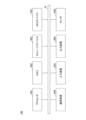
- FIG. 1 is a diagram showing an example of the system configuration of a radio communication system according to this embodiment.
- the radio communication system 1 includes, for example, a user terminal 100 that is a radio station used by a user, and a prediction device 10 that can communicate with the user terminal 100 .
- the prediction device 10 is, for example, an information processing device having a computer configuration, or a system including a plurality of computers.
- the prediction device 10 estimates the radio quality at the estimated position based on the current position of the user terminal 100, the estimated position of the user terminal 100 after a predetermined time has elapsed, and the measured received power of the user terminal 100 at the current position. Perform radio quality prediction processing to predict.
- the user terminal 100 selects a radio base station 2 having better radio quality than other radio base stations 2 among a plurality of radio base stations 2, for example, a predetermined radio base station such as 5G (5th. Generation) or LTE (Long Term Evolution). It is a wireless station that connects by wireless communication.
- the user terminal 100 can communicate with the prediction device 10 via the radio base station 2 or the like, inquires of the prediction device 10 about the radio quality at the estimated position, and obtains the radio quality at the estimated position notified from the prediction device 10. Based on the predicted value, for example, communication control such as handover is performed.
- ⁇ Functional configuration> (Functional configuration of prediction device) Prediction device 10, for example, acquisition unit 11, first prediction unit 12, correction unit 13, second prediction unit 14, notification unit 15, reception It implements a power predictor 21, a radio quality predictor 22, and the like.
- Prediction device 10 for example, acquisition unit 11, first prediction unit 12, correction unit 13, second prediction unit 14, notification unit 15, reception It implements a power predictor 21, a radio quality predictor 22, and the like.
- each of the functional configurations described above is not limited to a physical machine (computer), and may be implemented by, for example, a program executed by a virtual machine on a cloud. Further, each functional configuration described above may be distributed and arranged in separate physical machines or virtual machines. Furthermore, at least part of each of the functional configurations described above may be realized by hardware.
- the acquisition unit 11 executes an acquisition process for acquiring the current position of the user terminal 100, the estimated position of the user terminal 100 after a predetermined time has passed, and the measured received power of the user terminal 100 at the current position. For example, the acquisition unit 11 acquires the current position of the user terminal 100, the estimated position, and the measured value of the received power included in the inquiry transmitted by the user terminal 100.
- FIG. 1 A block diagram illustrating an acquisition process for acquiring the current position of the user terminal 100, the estimated position of the user terminal 100 after a predetermined time has passed, and the measured received power of the user terminal 100 at the current position.
- First prediction unit 12 uses received power predictor 21 to generate a predicted value of received power at the current position of user terminal 100 (hereinafter referred to as first predicted value P1) and a predicted value of received power at the estimated position.
- a first prediction process for predicting a predicted value (hereinafter referred to as a second predicted value P2) is executed.
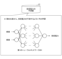
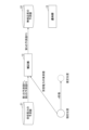
- FIG. 2 is a diagram for explaining the received power predictor 21 according to this embodiment.
- the received power predictor 21 is a computer, storage unit, device, or the like having a first neural network 201 pre-trained to predict the received power at the current position using the current position (for example, latitude and longitude) as a feature value. is.
- the first prediction unit 12 inputs the current position of the user terminal 100 acquired by the acquisition unit 11 to the trained first neural network 201 of the reception power predictor 21, thereby calculating the current position of the user terminal 100. A first estimate P1 of the received power at the location is obtained. Similarly, the first prediction unit 12 inputs the estimated position of the user terminal 100 acquired by the acquisition unit 11 to the trained first neural network 201 included in the reception power predictor 21, so that the user terminal A second estimate P2 of the received power at the 100 estimated locations is obtained.
- the correcting unit 13 corrects the second predicted value P2 based on the result of comparison between the measured value of received power acquired by the acquiring unit 11 and the measured value of received power predicted by the first predicting unit 12.
- a third predicted value P3 is obtained.
- the correction unit 13 calculates the third predicted value P3 using the following formula (1).
- P3 (measured value of received power - P1) + P2 (1)
- the present invention is not limited to this, and the correction unit may calculate the third predicted value P3 using another formula such as the following formula (2).
- the predetermined time (n seconds) for obtaining the estimated position of the user terminal 100 is set to a sufficiently short time so that the distance between the current position of the user terminal 100 and the estimated position does not become too large. It is desirable to keep Also, it is desirable that n in the predetermined time (n seconds) be a set value that can be changed by an administrator or the like.
- the second prediction unit 14 uses the radio quality predictor 22 and the third prediction value P3 corrected by the correction unit 13 to predict the radio quality (for example, throughput) of the user terminal 100 at the estimated position. 2 prediction processing is executed.
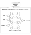
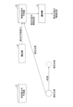
- FIG. 3 is a diagram for explaining the radio quality predictor 22 according to this embodiment.
- the wireless quality predictor 22 uses a plurality of pieces of information including the current position and the received power as feature quantities, and has a computer having a second neural network 301 trained in advance to predict wireless quality such as throughput, a storage unit, Or a device or the like.
- the plurality of pieces of information may include, for example, time information such as time and time period, or calendar information such as weekdays, weekends, and holidays.
- the second prediction unit 14 wirelessly transmits a plurality of pieces of information including the estimated position of the user terminal 100 after the elapse of the predetermined time acquired by the acquisition unit 11 and the third prediction value P3 corrected by the correction unit 13. Input to the trained second neural network 301 of the quality predictor 22 . Thereby, the second prediction unit 14 can obtain a predicted value of radio quality such as throughput at the estimated position of the user terminal 100 .
- the predicted value of radio quality is not limited to throughput, and may be other radio quality values such as error rate and retransmission rate.
- the notification unit 15 notifies the user terminal 100 of the predicted value of radio quality at the estimated position of the user terminal 100 predicted by the second prediction unit 14 .
- the functional configuration of the prediction device 10 shown in FIG. 1 is an example.
- the received power predictor 21 or the radio quality predictor 22 or the like may be implemented by a computer or the like external to the prediction device 10 .
- the trained first neural network 201 included in the received power predictor 21 may be included in the first predictor 12 .
- second prediction unit 14 may have trained second neural network 301 of radio quality predictor 22 .
- a computer provided in the user terminal 100 executes a predetermined program, so that the user terminal 100, for example, has a wireless communication unit 101, a position acquisition unit 102, a calculation unit 103, a reception power acquisition unit 104, an inquiry unit 105, and a storage unit 106. , the information receiving unit 107, the communication control unit 108, and the like. It should be noted that at least part of the functional configurations described above may be realized by hardware.
- the wireless communication unit 101 performs predetermined wireless communication with one or more wireless base stations 2 under the control of the communication control unit 108 .
- the position acquisition unit 102 acquires the current position of the user terminal 100 using, for example, a GPS (Global Positioning System) device or the like.
- the calculation unit 103 calculates, for example, the current position of the user terminal 100 acquired by the position acquisition unit 102 and the movement of the user terminal 100 measured by a sensor such as an acceleration sensor or an angle sensor, and a predetermined time (n seconds) has elapsed. Calculation processing for calculating the estimated position of the user terminal 100 is executed later. Alternatively, the calculation unit 103 stores the history of the current position of the user terminal 100 acquired by the position acquisition unit 102 in the storage unit 106, and based on this history, the user terminal 100 after a predetermined time (n seconds) has passed. An estimated position of the terminal 100 may be estimated. Note that, in the present embodiment, any method may be used for the calculation unit 103 to estimate the estimated position of the user terminal 100 after a predetermined period of time has elapsed.
- the received power acquisition unit 104 executes a received power acquisition process of acquiring, from the wireless communication unit 101, the communication control unit 108, or the like, the measured value of the received power of the radio wave that the wireless communication unit 101 receives from the wireless base station 2.
- the inquiry unit 105 executes an inquiry process of transmitting an inquiry including the current location of the user terminal 100, the estimated location of the user terminal 100 after a predetermined time has elapsed, and the measured received power value at the current location to the prediction device 10. do.
- the storage unit 106 stores, for example, various information such as a history of the current location of the user terminal 100, or data.
- the information receiving unit 107 executes information receiving processing for receiving the predicted value of the communication quality at the estimated position notified from the prediction device 10 in response to the inquiry by the inquiry unit 105 .
- the communication control unit 108 executes communication control processing such as call control of wireless communication by the wireless communication unit 101 .
- the communication control unit 108 determines whether or not to perform handover based on the predicted value of the communication quality at the estimated position received by the information receiving unit 107, and controls the wireless communication unit 101 when handover is performed. Execute handover.
- the system configuration and functional configuration of the wireless communication system 1 shown in FIG. 1 are examples.
- the acquisition unit 11, the notification unit 15, the inquiry unit 105, the information reception unit 107, and the like in FIG. 1 are unnecessary.
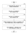
- FIG. 4 is a flowchart showing an example of radio quality prediction processing according to this embodiment.
- This process shows an example of the radio quality prediction process executed by the radio communication system 1 .
- This process is executed by the prediction device 10 in FIG. 1, for example.
- the user terminal 100 includes the first predictor 12, the corrector 13, the second predictor 14, the received power predictor 21, the radio quality predictor 22, and the like.
- the processing in FIG. 4 may be executed by the user terminal 100.
- FIG. the following description will be given assuming that the prediction device 10 performs the radio quality prediction processing shown in FIG.
- step S401 the acquisition unit 11 acquires the current position of the user terminal 100, the estimated position of the user terminal 100 after a predetermined time has elapsed, and the measured received power of the user terminal 100 at the current position. For example, when receiving an inquiry from the user terminal 100, the acquiring unit 11 acquires the current position, the estimated position, and the measured received power of the user terminal 100 included in the inquiry.
- the first prediction unit 12 In steps S402 and S403, the first prediction unit 12 generates a first predicted value P1 of received power at the current position of the user terminal 100 and a first predicted value P1 of received power at the estimated position of the user terminal 100 after a predetermined time has elapsed. A first prediction process for predicting a predicted value P2 of 2 is executed.
- FIG. 5 is a diagram for explaining the first prediction process according to this embodiment.
- the current position of the user terminal 100 is called “current position”
- the estimated position of the user terminal 100 after a predetermined time (n seconds) is called “estimated position”.
- the predetermined time n seconds is a set value set by an administrator, designer, or the like, and is set in advance so that good prediction results can be obtained.
- the first prediction unit 12 inputs the current position (for example, latitude and longitude) acquired by the acquisition unit 11 to the trained first neural network 201 of the reception power predictor 21 described in FIG.
- the output received power is set as the first predicted value P1 of the received power at the current position.
- the first prediction unit 12 applies the estimated position (for example, latitude and longitude) acquired by the acquisition unit 11 to the trained first neural network 201 of the reception power predictor 21 described in FIG.
- the input and output received power is used as the second predicted value P2 of the received power at the estimated position.
- step S404 of FIG. 4 the correction unit 13 calculates the second A third predicted value P3 is obtained by correcting the predicted value P2 of .
- FIG. 6 is a diagram for explaining correction processing according to the present embodiment.
- the correction unit 13 compares the measured received power value at the current position acquired by the acquisition unit 11 with the first prediction value P1 predicted by the first prediction unit 12, and performs a second prediction based on the comparison result.
- a third predicted value P3 is obtained by correcting the value P2.
- the correction unit 13 calculates the third predicted value P3 using the formula (1) or formula (2) described above.
- the correction unit 13 calculates, for example, the difference between the actual measurement value of the received power at the current location and the first predicted value P1, and adds or subtracts the calculated difference to or from the second predicted value P2.
- a third predicted value P3 of the received power at the estimated position which takes into account the influence of the building, is obtained.
- step S405 of FIG. 4 the third prediction value P3 corrected by the correction unit 13 is used to execute a second prediction process of predicting the throughput (an example of radio quality) of the user terminal 100 at the estimated position.
- FIG. 7 is a diagram for explaining the second prediction process according to this embodiment.
- the second prediction unit 14 uses the wireless quality predictor 22 described with reference to FIG. input to the trained second neural network 301 . Also, the second prediction unit 14 uses the throughput output from the trained second neural network 301 as the predicted value of the radio quality at the estimated position.
- the notification unit 15 notifies the user terminal 100 or the like of the predicted value of the radio quality at the estimated position predicted by the second prediction unit 14 .
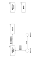
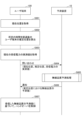
- FIG. 8 is a sequence diagram showing an example of processing of the wireless communication system according to this embodiment. This processing shows an example of processing of the entire radio communication system corresponding to the radio quality prediction processing described with reference to FIG.
- the user terminal 100 is connected to one of the radio base stations 2 by predetermined radio communication, and can communicate with the prediction device 10.
- step S801 the location acquisition unit 102 of the user terminal 100 acquires the current location of the user terminal 100 using, for example, a GPS device. Based on the current position of the user terminal 100 and the movement of the user terminal 100 measured by the sensor, the estimated position of the user terminal 100 after a predetermined time (n seconds) has elapsed is calculated.
- step S803 the received power acquisition unit 104 of the user terminal 100 acquires the measured value of the received power of radio waves received by the wireless communication unit 101 from the wireless base station 2 from the wireless communication unit 101, the communication control unit 108, or the like. .
- step S804 the inquiry unit 105 of the user terminal 100 transmits an inquiry including the current position of the user terminal 100, the estimated position, and the actual measurement of the received power to the prediction device 10.
- step S805 upon receiving an inquiry from the user terminal 100, the prediction device 10 executes the radio quality prediction process described with reference to FIG.
- step S806 the notification unit 15 of the prediction device 10 notifies the user terminal 100 of the predicted value of radio quality at the estimated position.
- step S807 the communication control unit 108 of the user terminal 100 controls handover and the like of the user terminal 100 based on the predicted value of radio quality at the estimated position received by the information receiving unit 107.
- FIG. 9 is a diagram showing an example of the hardware configuration of the prediction device 10 according to this embodiment.
- the prediction device 10 has, for example, the configuration of a computer 900 as shown in FIG.
- computer 900 has processor 901, memory 902, storage device 903, communication device 904, input device 905, output device 906, bus B and the like.
- the processor 901 is, for example, an arithmetic device such as a CPU (Central Processing Unit) that implements various functions by executing a predetermined program.
- the memory 902 is a storage medium readable by the computer 900, and includes, for example, RAM (Random Access Memory), ROM (Read Only Memory), and the like.
- the storage device 903 is a computer-readable storage medium, and may include, for example, a HDD (Hard Disk Drive), an SSD (Solid State Drive), various optical discs, magneto-optical discs, and the like.
- the communication device 904 includes one or more pieces of hardware (communication devices) for communicating with other devices via a wireless or wired network.
- the input device 905 is an input device (for example, keyboard, mouse, microphone, switch, button, sensor, etc.) that receives input from the outside.
- the output device 906 is an output device (for example, display, speaker, LED lamp, etc.) that outputs to the outside. Note that the input device 905 and the output device 906 may be integrated (for example, an input/output device such as a touch panel display).
- a bus B is commonly connected to each of the components described above, and transmits, for example, address signals, data signals, and various control signals.
- the processor 901 is not limited to a CPU, and may be, for example, a DSP (Digital Signal Processor), a PLD (Programmable Logic Device), or an FPGA (Field Programmable Gate Array).
- FIG. 10 is a diagram showing an example of a hardware configuration of a user terminal according to this embodiment.
- the user terminal 100 has a GPS device 1001, a sensor 1002, etc. in addition to the hardware configuration of the computer 900 described with reference to FIG.
- the GPS device 1001 is a positioning device that receives positioning signals transmitted by GPS satellites and outputs position information indicating the current position of the user terminal 100 .
- the sensor 1002 is, for example, a detection device that detects movement of the user terminal 100, such as an acceleration sensor or an angle sensor.
- the prediction device 10 in this embodiment is not limited to being realized by a dedicated device, and may be realized by a general-purpose computer. In that case, a program for realizing this function may be recorded in a computer-readable recording medium, and the program recorded in this recording medium may be read into a computer system and executed. It should be noted that the "computer system” referred to here includes hardware such as an OS and peripheral devices.
- “computer-readable recording medium” includes various storage devices such as portable media such as flexible disks, magneto-optical disks, ROMs and CD-ROMs, and hard disks built into computer systems.
- “computer-readable recording medium” refers to a program that dynamically retains programs for a short period of time, like a communication line when transmitting a program via a network such as the Internet or a communication line such as a telephone line. It may also include something that holds the program for a certain period of time, such as a volatile memory inside a computer system that serves as a server or client in that case.
- the above program may be for realizing part of the functions described above, or may be capable of realizing the functions described above in combination with a program already recorded in a computer system, It may be implemented using hardware such as PLD (Programmable Logic Device) or FPGA (Field Programmable Gate Array).
- PLD Programmable Logic Device
- FPGA Field Programmable Gate Array
- the prediction device 10 uses the received power predictor 21 to obtain the first predicted value P1 of the received power at the current position and the first predicted value P1 of the received power at the estimated position after the lapse of a predetermined time. 2 predicted value P2. Further, the prediction device 10 corrects the second predicted value P2 using the comparison result (difference or ratio) between the measured received power value at the current position and the first predicted value P1, and corrects the corrected third The radio quality at the estimated position is estimated using the predicted value P3 of .
- a radio quality prediction method that performs (Section 2) 2.
- (Section 3) Item 1 or 2 wherein the wireless quality predictor has a second neural network trained in advance to predict the wireless quality using a plurality of pieces of information including current position and received power as feature quantities.
- the radio quality prediction method according to .
- a wireless communication system including a user terminal and a prediction device communicable with the user terminal, The prediction device is an acquisition unit that acquires, from the user terminal, the current location of the user terminal, an estimated location of the user terminal after a predetermined time has elapsed, and a measured received power value of the user terminal at the current location; A first prediction that predicts a first prediction value that is a prediction value of reception power at the current position and a second prediction value that is a prediction value of reception power at the estimated position using a reception power predictor.
- a wireless communication system comprising: (Section 6)
- the user terminal is an inquiry unit that transmits an inquiry including a current position of the user terminal, an estimated position of the user terminal after a predetermined time has elapsed, and an actual measurement value of received power of the user terminal at the current position to the prediction device; a communication control unit that controls handover of the user terminal based on the predicted value of radio quality of the user terminal at the estimated position notified from the prediction device; 6.
Landscapes
- Engineering & Computer Science (AREA)
- Computer Networks & Wireless Communication (AREA)
- Signal Processing (AREA)
- Mobile Radio Communication Systems (AREA)
Priority Applications (2)
| Application Number | Priority Date | Filing Date | Title |
|---|---|---|---|
| JP2023567441A JP7729400B2 (ja) | 2021-12-16 | 2021-12-16 | 無線品質予測方法、及び無線通信システム |
| PCT/JP2021/046558 WO2023112263A1 (ja) | 2021-12-16 | 2021-12-16 | 無線品質予測方法、及び無線通信システム |
Applications Claiming Priority (1)
| Application Number | Priority Date | Filing Date | Title |
|---|---|---|---|
| PCT/JP2021/046558 WO2023112263A1 (ja) | 2021-12-16 | 2021-12-16 | 無線品質予測方法、及び無線通信システム |
Publications (1)
| Publication Number | Publication Date |
|---|---|
| WO2023112263A1 true WO2023112263A1 (ja) | 2023-06-22 |
Family
ID=86773880
Family Applications (1)
| Application Number | Title | Priority Date | Filing Date |
|---|---|---|---|
| PCT/JP2021/046558 Ceased WO2023112263A1 (ja) | 2021-12-16 | 2021-12-16 | 無線品質予測方法、及び無線通信システム |
Country Status (2)
| Country | Link |
|---|---|
| JP (1) | JP7729400B2 (enExample) |
| WO (1) | WO2023112263A1 (enExample) |
Citations (3)
| Publication number | Priority date | Publication date | Assignee | Title |
|---|---|---|---|---|
| JP2012209744A (ja) * | 2011-03-29 | 2012-10-25 | Casio Comput Co Ltd | 情報処理端末及び情報処理方法、並びにプログラム |
| JP2015126405A (ja) * | 2013-12-26 | 2015-07-06 | 日本電気株式会社 | カバレッジホール評価装置と方法及びプログラム並びに無線通信装置 |
| JP2018032939A (ja) * | 2016-08-23 | 2018-03-01 | 日本電信電話株式会社 | 品質推定装置及び品質推定方法 |
Family Cites Families (3)
| Publication number | Priority date | Publication date | Assignee | Title |
|---|---|---|---|---|
| US12170547B2 (en) * | 2019-04-26 | 2024-12-17 | Nippon Telegraph And Telephone Corporation | Terminal and communication system |
| JP7184171B2 (ja) * | 2019-04-26 | 2022-12-06 | 日本電信電話株式会社 | 通信装置及び通信システム |
| JP7276481B2 (ja) * | 2019-10-01 | 2023-05-18 | 日本電信電話株式会社 | 移動端末及び通信品質予測方法 |
-
2021
- 2021-12-16 JP JP2023567441A patent/JP7729400B2/ja active Active
- 2021-12-16 WO PCT/JP2021/046558 patent/WO2023112263A1/ja not_active Ceased
Patent Citations (3)
| Publication number | Priority date | Publication date | Assignee | Title |
|---|---|---|---|---|
| JP2012209744A (ja) * | 2011-03-29 | 2012-10-25 | Casio Comput Co Ltd | 情報処理端末及び情報処理方法、並びにプログラム |
| JP2015126405A (ja) * | 2013-12-26 | 2015-07-06 | 日本電気株式会社 | カバレッジホール評価装置と方法及びプログラム並びに無線通信装置 |
| JP2018032939A (ja) * | 2016-08-23 | 2018-03-01 | 日本電信電話株式会社 | 品質推定装置及び品質推定方法 |
Also Published As
| Publication number | Publication date |
|---|---|
| JP7729400B2 (ja) | 2025-08-26 |
| JPWO2023112263A1 (enExample) | 2023-06-22 |
Similar Documents
| Publication | Publication Date | Title |
|---|---|---|
| US10897493B2 (en) | Systems and methods for predictive user location and content replication | |
| US9118776B2 (en) | Location monitoring feature of a mobile device for activating an application subsystem | |
| De Oliveira et al. | An efficient directed localization recursion protocol for wireless sensor networks | |
| JP6851309B2 (ja) | 情報を収集及び処理する方法、クライアント端末、及びサーバ | |
| US20190011571A1 (en) | Systems, methods and devices for satellite navigation reconciliation | |
| CN104995973B (zh) | 移动设备定位系统 | |
| KR101517090B1 (ko) | 모바일 디바이스 위치 결정에 대한 방법들 및 장치 | |
| US20160280401A1 (en) | Systems, methods and devices for satellite navigation | |
| CN111491332A (zh) | 动态服务迁移方法及装置 | |
| Kasana et al. | Location error resilient geographical routing for vehicular ad‐hoc networks | |
| JP2009278421A (ja) | 無線品質劣化予測システム | |
| WO2015073134A1 (en) | Using rssi and rtt information for choosing access points to associate with | |
| Rashid et al. | Dead reckoning localisation technique for mobile wireless sensor networks | |
| CN105393141A (zh) | 用于将位置参数提供给移动应用程序的方法和设备 | |
| Sedighian Kashi | Area coverage of heterogeneous wireless sensor networks in support of Internet of Things demands | |
| WO2015193727A1 (en) | Method, apparatus and readable medium for an api notifying an application that qos will change in future | |
| US10674313B2 (en) | Automatic optimization procedure termination using a smoothing-based technique | |
| Jin et al. | Detecting node failures in mobile wireless networks: A probabilistic approach | |
| US20180195867A1 (en) | Systems and methods for indoor and outdoor mobile device navigation | |
| JP6101601B2 (ja) | 情報処理装置及び位置測位方法 | |
| JP7729400B2 (ja) | 無線品質予測方法、及び無線通信システム | |
| KR20130000824A (ko) | 단말기 측위 시스템 및 방법, 측위 장치 및 그 장치의 구동 방법, 클라우드 컴퓨팅 서비스 장치 및 그 장치의 구동 방법, 액세스포인트 및 액세스포인트의 구동 방법, 단말기 | |
| KR102612792B1 (ko) | 전자 장치 및 전자 장치의 관심 영역 진입 판단 방법 | |
| JP7779385B2 (ja) | 無線品質予測システム、無線品質予測装置、無線品質予測方法、及びプログラム | |
| Liu et al. | Edge big data-enabled low-cost indoor localization based on Bayesian analysis of RSS |
Legal Events
| Date | Code | Title | Description |
|---|---|---|---|
| 121 | Ep: the epo has been informed by wipo that ep was designated in this application |
Ref document number: 21968178 Country of ref document: EP Kind code of ref document: A1 |
|
| ENP | Entry into the national phase |
Ref document number: 2023567441 Country of ref document: JP Kind code of ref document: A |
|
| NENP | Non-entry into the national phase |
Ref country code: DE |
|
| 122 | Ep: pct application non-entry in european phase |
Ref document number: 21968178 Country of ref document: EP Kind code of ref document: A1 |