WO2023112082A1 - コントローラ、制御システム、学習装置および推論装置 - Google Patents
コントローラ、制御システム、学習装置および推論装置 Download PDFInfo
- Publication number
- WO2023112082A1 WO2023112082A1 PCT/JP2021/045769 JP2021045769W WO2023112082A1 WO 2023112082 A1 WO2023112082 A1 WO 2023112082A1 JP 2021045769 W JP2021045769 W JP 2021045769W WO 2023112082 A1 WO2023112082 A1 WO 2023112082A1
- Authority
- WO
- WIPO (PCT)
- Prior art keywords
- motor
- model
- control
- correction
- controller
- Prior art date
- Legal status (The legal status is an assumption and is not a legal conclusion. Google has not performed a legal analysis and makes no representation as to the accuracy of the status listed.)
- Ceased
Links
Images







Classifications
-
- H—ELECTRICITY
- H02—GENERATION; CONVERSION OR DISTRIBUTION OF ELECTRIC POWER
- H02P—CONTROL OR REGULATION OF ELECTRIC MOTORS, ELECTRIC GENERATORS OR DYNAMO-ELECTRIC CONVERTERS; CONTROLLING TRANSFORMERS, REACTORS OR CHOKE COILS
- H02P29/00—Arrangements for regulating or controlling electric motors, appropriate for both AC and DC motors
- H02P29/02—Providing protection against overload without automatic interruption of supply
- H02P29/024—Detecting a fault condition, e.g. short circuit, locked rotor, open circuit or loss of load
- H02P29/028—Detecting a fault condition, e.g. short circuit, locked rotor, open circuit or loss of load the motor continuing operation despite the fault condition, e.g. eliminating, compensating for or remedying the fault
-
- G—PHYSICS
- G05—CONTROLLING; REGULATING
- G05B—CONTROL OR REGULATING SYSTEMS IN GENERAL; FUNCTIONAL ELEMENTS OF SUCH SYSTEMS; MONITORING OR TESTING ARRANGEMENTS FOR SUCH SYSTEMS OR ELEMENTS
- G05B13/00—Adaptive control systems, i.e. systems automatically adjusting themselves to have a performance which is optimum according to some preassigned criterion
- G05B13/02—Adaptive control systems, i.e. systems automatically adjusting themselves to have a performance which is optimum according to some preassigned criterion electric
- G05B13/04—Adaptive control systems, i.e. systems automatically adjusting themselves to have a performance which is optimum according to some preassigned criterion electric involving the use of models or simulators
- G05B13/042—Adaptive control systems, i.e. systems automatically adjusting themselves to have a performance which is optimum according to some preassigned criterion electric involving the use of models or simulators in which a parameter or coefficient is automatically adjusted to optimise the performance
-
- H—ELECTRICITY
- H02—GENERATION; CONVERSION OR DISTRIBUTION OF ELECTRIC POWER
- H02P—CONTROL OR REGULATION OF ELECTRIC MOTORS, ELECTRIC GENERATORS OR DYNAMO-ELECTRIC CONVERTERS; CONTROLLING TRANSFORMERS, REACTORS OR CHOKE COILS
- H02P23/00—Arrangements or methods for the control of AC motors characterised by a control method other than vector control
- H02P23/20—Controlling the acceleration or deceleration
-
- H—ELECTRICITY
- H02—GENERATION; CONVERSION OR DISTRIBUTION OF ELECTRIC POWER
- H02P—CONTROL OR REGULATION OF ELECTRIC MOTORS, ELECTRIC GENERATORS OR DYNAMO-ELECTRIC CONVERTERS; CONTROLLING TRANSFORMERS, REACTORS OR CHOKE COILS
- H02P6/00—Arrangements for controlling synchronous motors or other dynamo-electric motors using electronic commutation dependent on the rotor position; Electronic commutators therefor
- H02P6/34—Modelling or simulation for control purposes
-
- H—ELECTRICITY
- H02—GENERATION; CONVERSION OR DISTRIBUTION OF ELECTRIC POWER
- H02P—CONTROL OR REGULATION OF ELECTRIC MOTORS, ELECTRIC GENERATORS OR DYNAMO-ELECTRIC CONVERTERS; CONTROLLING TRANSFORMERS, REACTORS OR CHOKE COILS
- H02P29/00—Arrangements for regulating or controlling electric motors, appropriate for both AC and DC motors
- H02P29/02—Providing protection against overload without automatic interruption of supply
- H02P29/024—Detecting a fault condition, e.g. short circuit, locked rotor, open circuit or loss of load
- H02P29/0241—Detecting a fault condition, e.g. short circuit, locked rotor, open circuit or loss of load the fault being an overvoltage
-
- H—ELECTRICITY
- H02—GENERATION; CONVERSION OR DISTRIBUTION OF ELECTRIC POWER
- H02P—CONTROL OR REGULATION OF ELECTRIC MOTORS, ELECTRIC GENERATORS OR DYNAMO-ELECTRIC CONVERTERS; CONTROLLING TRANSFORMERS, REACTORS OR CHOKE COILS
- H02P29/00—Arrangements for regulating or controlling electric motors, appropriate for both AC and DC motors
- H02P29/02—Providing protection against overload without automatic interruption of supply
- H02P29/024—Detecting a fault condition, e.g. short circuit, locked rotor, open circuit or loss of load
- H02P29/027—Detecting a fault condition, e.g. short circuit, locked rotor, open circuit or loss of load the fault being an over-current
-
- H—ELECTRICITY
- H02—GENERATION; CONVERSION OR DISTRIBUTION OF ELECTRIC POWER
- H02P—CONTROL OR REGULATION OF ELECTRIC MOTORS, ELECTRIC GENERATORS OR DYNAMO-ELECTRIC CONVERTERS; CONTROLLING TRANSFORMERS, REACTORS OR CHOKE COILS
- H02P29/00—Arrangements for regulating or controlling electric motors, appropriate for both AC and DC motors
- H02P29/10—Arrangements for regulating or controlling electric motors, appropriate for both AC and DC motors for preventing overspeed or under speed
Definitions
- the present disclosure relates to a controller, control system, learning device, and reasoning device connected to a motor control device that controls the operation of a motor.
- a servo motor control device that performs follow-up control.
- a control device In general servomotor control, a control device is known that performs PID (Proportional Integral Differential) control so as to follow an externally input position command value and speed command value.
- PID Proportional Integral Differential
- the control input is limited for the purpose of protecting the servomotor. Therefore, a control device with a limited control input has a windup phenomenon that overshoots the output response when the control input is saturated when a movement command that exceeds the control input limit is given. Due to this, the position command, speed command, etc. cannot be followed, causing deterioration of control performance such as overshoot, and instability of the control system.
- Patent Document 1 discloses that, as a measure against saturation with respect to the control input limit, the control input to a controlled object having a limit to the control input to the motor is predicted to be limited.
- a technique for preventing saturation of control input is disclosed by correcting the positional deviation by using
- a controller which is a host control device connected to a motor control device, generates a position command based on a program, such as a G-code program, that determines the path of the motor to be driven.
- a program such as a G-code program
- the motor control device corrects the position deviation, which is the difference between the position command input from the controller and the detected motor position, in order to prevent the windup phenomenon. are being implemented. Therefore, when the motor control device performs such correction, there is a problem that the object to be driven by the motor moves through a path different from the path assumed by the controller.
- the present disclosure has been made in view of the above.
- the purpose is to get the controller to update.
- the present disclosure is a controller that outputs a position command to a motor control device that supplies current to a motor to control its operation.
- the controller analyzes an operation program that defines the path of the object to be driven by the operation of the motor, and has a program analysis unit that outputs analysis data, and a machine model that calculates the acceleration that the motor can output.
- a position command generator that generates a position command based on the machine model and updates the machine model when the control input to the motor exceeds a preset control input limit and saturates.
- the controller of the present disclosure has the effect of being able to update the mechanical model used when generating the position command for the motor control device based on the saturation state while suppressing the deterioration of the control performance due to the saturation of the control input. Play.
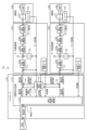
- FIG. 1 is a diagram showing a configuration example of a control system according to Embodiment 1;
- FIG. FIG. 4 is a diagram showing a configuration example of a pre-correction position command calculation unit included in the controller according to the first embodiment;
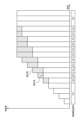
- FIG. 4 is a diagram showing an example of a movement amount before acceleration/deceleration processing by an acceleration/deceleration processing unit included in a pre-correction position command calculation unit of the controller according to Embodiment 1;
- FIG. 5 is a diagram showing an example of a movement amount after acceleration/deceleration processing by an acceleration/deceleration processing unit included in a pre-correction position command calculation unit of the controller according to Embodiment 1;
- FIG. 5 is a diagram showing an example of a motor characteristic model held by an acceleration/deceleration processing unit included in a pre-correction position command calculation unit of the controller according to Embodiment 1;
- FIG. 4 is a diagram showing a configuration example of an acceleration correction calculation unit included in the controller according to Embodiment 1;
- FIG. 5 is a diagram showing an example of a difference in movement amount when the acceleration correction calculation unit of the controller according to Embodiment 1 corrects the acceleration;
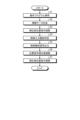
- 3 is a flow chart showing an operation for suppressing deterioration of control performance due to saturation of control input in the controller according to the first embodiment;
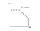
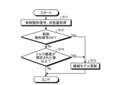
- FIG. 4 is a diagram showing an image of plotting, as motor characteristics, the motor torque calculated from the state quantity when the control saturation signal is ON in the acceleration/deceleration processing unit included in the pre-correction position command calculation unit of the controller according to the first embodiment; 4 is a flow chart showing the operation of updating the machine model in the controller according to the first embodiment based on the saturation state;
- FIG. 3 is a diagram showing a configuration example of hardware that implements the controller according to the first embodiment;
- FIG. 10 is a diagram showing a configuration example of a learning device applied to a controller according to Embodiment 4;
- FIG. 14 is a diagram schematically showing an example of a neural network used in the model generation unit of the learning device according to Embodiment 4;
- FIG. 11 is a diagram showing a configuration example of an inference device applied to a controller according to a fourth embodiment; Flowchart showing inference processing of the inference device according to the fourth embodiment FIG.
- FIG. 11 is a diagram showing an example of a case where a learning device and an inference device are installed outside a controller in Embodiment 4;
- FIG. 14 is a diagram showing an example of a case where a learning device and an inference device are installed inside a controller in Embodiment 4;
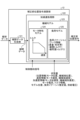
- FIG. 1 is a diagram showing a configuration example of a control system 40 according to Embodiment 1.
- the control system 40 includes a controller 10 and a motor control device 20 .
- the controller 10 suppresses deterioration of control performance due to saturation of the control input, and updates the mechanical model used when generating the position command for the motor control device 20 based on the saturation state. characterized by Each feature will be described below. First, suppression of deterioration of control performance due to saturation of control input will be described.
- saturation of the control input means exceeding a preset control input limit.
- the controller 10 is a host control device connected to the motor control device 20. Controller 10 outputs a position command to motor control device 20 .
- the motor control device 20 controls the operation of the motor 31 by supplying current to the motor 31 based on the position command.
- An encoder 33 that detects the motor position of the motor 31 and a load 32 that is driven by the operation of the motor 31 are connected to the motor 31 .
- Motor 31 and load 32 are collectively referred to as mechanical system 30 .
- the mechanical system 30 includes a drive shaft that drives a load 32 that constitutes a machine tool or the like. In the following description, the drive shaft is simply referred to as shaft.
- the controller 10 controls operations of a plurality of axes in a machine tool or the like
- the motor 31 and the motor control device 20 are prepared for each axis.
- the controller 10 targets one motor control device 20 and one mechanical system 30
- the encoder 33 may be included in the mechanical system 30 as shown in FIG.
- the motor control device 20 drives (operates) the motor 31 based on the corrected position command acquired from the controller 10 .
- the motor control device 20 includes a position deviation calculator 21, a position controller 22, a speed calculator 23, a speed deviation calculator 24, a speed controller 25, and a current limiter 26. , and a current control unit 27 .
- the position deviation calculation unit 21 calculates the position deviation between the corrected position command acquired from the controller 10 and the motor position of the motor 31 detected by the encoder 33 .
- the position control section 22 generates a speed command for the motor 31 based on the position deviation calculated by the position deviation calculation section 21 .
- the speed calculator 23 calculates the speed of the motor 31 by differentiating the motor position of the motor 31 detected by the encoder 33 .
- a speed deviation calculator 24 calculates a speed deviation between the speed command generated by the position controller 22 and the speed of the motor 31 calculated by the speed calculator 23 .
- the speed controller 25 generates a current command for the motor 31 based on the speed deviation calculated by the speed deviation calculator 24 .
- the current limiting unit 26 limits the current command generated by the speed control unit 25 to a motor maximum current Imax or less specified to protect the motor 31, and outputs a post-limiting current command. .
- the current limiting unit 26 limits the current command when the current command is equal to or greater than the maximum motor current Imax, and when the current command is less than the maximum motor current Imax, the current command is left as it is without limiting the current.
- the current control unit 27 generates and outputs a motor current I to the motor 31 based on the post-limiting current command and the motor current I fed back.
- the controller 10 includes a program analysis section 11 , pre-correction position command calculation section 12 , acceleration correction calculation section 13 , and position command calculation section 14 .
- the pre-correction position command calculator 12 , the acceleration correction calculator 13 , and the position command calculator 14 constitute a position command generator 15 .
- the program analysis unit 11 analyzes an operation program input from the outside, and outputs analysis results as analysis data.
- the operating program is composed of a plurality of instruction blocks.
- the operation program is, for example, a program that defines the path of operation of the load 32 that is driven by the operation of the motor 31 .
- a motion path of the load 32 defined by the motion program is referred to as a command path.
- the analysis data is information necessary for movement of each axis, such as movement amount of each axis for each command block, command feed speed, and command information.
- the command information is, for example, a G code.
- the position command generator 15 has a machine model for calculating the acceleration that the motor 31 can output, and generates a position command based on the analysis data and the machine model. Further, the position command generator 15 updates the machine model when the control input to the motor 31 exceeds a preset control input limit and saturates.
- the operation of the position command generator 15 will be described in detail below as the operations of the pre-correction position command calculator 12, the acceleration correction calculator 13, and the position command calculator 14. FIG.
- the pre-correction position command calculation unit 12 has a machine model for calculating the acceleration that the motor 31 can output, and calculates the pre-correction position command based on the analysis data and the machine model. Specifically, the pre-correction position command calculation unit 12 generates interpolation data based on the analysis data acquired from the program analysis unit 11, and generates a pre-correction position command for accelerating and decelerating the motor 31 based on the interpolation data. to generate FIG. 2 is a diagram showing a configuration example of the pre-correction position command calculator 12 included in the controller 10 according to the first embodiment.
- the pre-correction position command calculation unit 12 includes an interpolation data generation unit 121 and an acceleration/deceleration processing unit 122 .
- the interpolation data generation unit 121 generates interpolation data based on the analysis data acquired from the program analysis unit 11.
- the interpolation data includes information used to generate speed calculation values such as a target speed in addition to data representing the amount of movement for one control cycle.
- the acceleration/deceleration processing unit 122 receives the interpolated data obtained from the interpolated data generation unit 121 and the state quantity described later, performs acceleration/deceleration processing using the mechanical model 123, and performs acceleration/deceleration processing within the range of torque that the motor 31 can output.
- a pre-correction position command is calculated by integrating the amount of movement for one control cycle for each axis for acceleration/deceleration driving.
- the machine model 123 includes a motor characteristic model 124 that indicates torque-speed characteristics that the motor 31 can output, and a load model 125 that includes information on the load 32 to be driven.
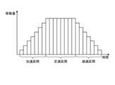
- FIG. 3 is a diagram showing an example of the amount of movement before acceleration/deceleration processing by the acceleration/deceleration processing unit 122 included in the pre-correction position command calculation unit 12 of the controller 10 according to the first embodiment.
- FIG. 4 is a diagram showing an example of a movement amount after acceleration/deceleration processing by the acceleration/deceleration processing unit 122 included in the pre-correction position command calculation unit 12 of the controller 10 according to the first embodiment.
- the horizontal axis indicates time
- the vertical axis indicates the amount of movement.
- the amount of movement corresponds to the amount of change in the position command for one control cycle, and corresponds to the speed command.
- FIG. 3 corresponds to interpolation data
- the amount of movement after the acceleration/deceleration processing by the acceleration/deceleration processing unit 122 is greater than the movement amount before the acceleration/deceleration processing shown in FIG. Because the amount is smaller, it takes longer to move the required amount of movement.
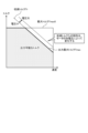
- FIG. 5 is a diagram showing an example of the motor characteristic model 124 held by the acceleration/deceleration processing unit 122 included in the pre-correction position command calculation unit 12 of the controller 10 according to the first embodiment.
- the torque that the motor 31 can output, that is, the maximum output torque Tmax is the smaller of the reduced torque Tr determined from The thick line shown in FIG. 5 is the maximum output torque Tmax.
- the maximum torque Tmax0 becomes the maximum output torque Tmax, and the voltage command applied to the motor 31, which is the control input. is limited, the reduced torque Tr becomes the maximum output torque Tmax.
- torque saturation the case where the current command, which is the control input, is limited because it exceeds the control input limit
- voltage saturation the case where the voltage command applied to the motor 31, which is the control input, is limited because it exceeds the control input limit.
- the load model 125 included in the mechanical model 123 held by the acceleration/deceleration processing unit 122 includes information such as load inertia J, workpiece information, friction torque T1, and unbalanced load torque T2.
- the work information includes, for example, information such as the weight of the work and the shape of the work.
- a work is an object to be machined by a machine tool when the controller 10 controls the operation of the machine tool.
- the acceleration/deceleration processing unit 122 calculates the pre-correction position command.
- the motor torque Tm can be calculated from the output torque Tout acting on the load 32 and the disturbance torque Td acting as a disturbance, as shown in Equation (1).
- Tm is motor torque [Nm]
- Tout is output torque [Nm]
- Td disturbance torque [Nm].
- the disturbance torque Td here can be calculated from the friction torque T1 and the unbalanced load torque T2 as shown in Equation (2).
- T1 friction torque [Nm] and T2 is unbalanced load torque [Nm].
- the angular acceleration ⁇ can be calculated from the output torque Tout and the load inertia J as shown in Equation (3).
- Equation (3) J is the load inertia [kg/m 2 ], which is the moment of inertia. That is, on the premise that the information possessed by the mechanical model 123 matches the object to be driven, the acceleration/deceleration processing unit 122 controls the motor characteristic model 124 and the load model 125 so that the motor torque Tm is equal to or less than the maximum output torque Tmax. If the angular acceleration ⁇ is determined on the basis of , it is possible to calculate a position command before correction that does not cause saturation of the control input.
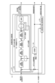
- the acceleration correction calculation unit 13 determines whether or not the control input to the motor 31 is saturated. When it is determined that the control input is saturated, the control saturation signal is turned ON and output, and the control input is saturated. If it is determined that it is not, the control saturation signal is turned off and output. Further, the acceleration correction calculation unit 13 calculates a position command correction value for correcting the pre-correction position command based on the control saturation signal. Specifically, the acceleration correction calculation unit 13 uses the pre-correction position command obtained from the pre-correction position command calculation unit 12 and the motor position obtained from the encoder 33 to generate a position command for correcting the pre-correction position command. Calculate the correction value. FIG.
- the acceleration correction calculation section 13 includes a model output section 131 , a model position deviation calculation section 133 , a comparison section 134 and a position command correction value calculation section 135 .
- a model output unit 131 receives as input the pre-correction position command calculated by the pre-correction position command calculation unit 12, and generates a model of the motor 31 using a motor control model 132 including a position control unit, a speed control unit, a current control unit, and the like. Calculate the position.
- the motor control model 132 simulates the motor control device 20, and outputs the motor position as the model position when the motor 31 is controlled without saturation of the control input.
- the portion corresponding to the mechanical system represented by the motor, load, and encoder is a model corresponding to the motor characteristic model 124 of the mechanical model 123 shown in FIG.
- the model position deviation between the model position calculated by the model position deviation calculator 133 described later and the motor position is zero.
- the model position and the motor position diverge, so the position droop, which is the deviation between the pre-correction position command and the motor position, expands, and the model position deviation also expands. . Therefore, the acceleration correction calculation unit 13 can determine the saturation of the control input by monitoring the model position deviation. Further, as described above, the saturation of the control input is mainly due to torque saturation or voltage saturation. Therefore, by reducing the motor acceleration, the motor torque Tm can be reduced, and the saturation of the control input can be eliminated.
- the model output unit 131 may acquire the information of the motor characteristic model 124 from the pre-correction position command calculation unit 12 as the information of the model corresponding to the motor characteristic model 124.
- the unit 12 updates the motor characteristic model 124 information on the updated motor characteristic model 124 may be acquired.
- the model position deviation calculation unit 133 calculates the deviation between the model position calculated by the model output unit 131 and the motor position of the motor 31 detected by the encoder 33, and outputs it as a model position deviation.
- the comparison unit 134 compares the model position deviation calculated by the model position deviation calculation unit 133 with a prescribed threshold value, and if the model position deviation is equal to or greater than the threshold value, determines that the control input has been saturated for some reason, and controls saturation. Output the signal as ON. On the other hand, when the model position deviation is less than the threshold value, the comparison unit 134 determines that saturation of the control input has not occurred, and outputs the control saturation signal as OFF.
- the threshold used in the comparison unit 134 may be a fixed value or a variable value. In the case of a fixed value, it is set in advance by the manufacturer or user of the controller 10 .
- a variable value for example, a value obtained by multiplying the position deviation between the pre-correction position command calculated in the motor control model 132 shown in FIG. 6 and the model position by a specified coefficient may be used as the threshold value.
- the threshold used by the comparison unit 134 is an example of control input limitation.
- the position command correction value calculation unit 135 corrects the position command based on the control saturation signal obtained from the comparison unit 134, the motor position obtained from the encoder 33, and the pre-correction position command obtained from the pre-correction position command calculation unit 12. Calculate values. Specifically, when the control saturation signal is turned ON, the position command correction value calculation unit 135 reduces the post-correction command acceleration that is the post-correction acceleration, that is, the amount of change in the post-correction position command for one control cycle. Then, it calculates and outputs a position command correction value for correcting the pre-correction position command.
- the position command correction value calculation unit 135 may correct the post-correction command acceleration to 0, or may correct it to decrease stepwise with a time constant. In either case, the aforementioned model position deviation acts to decrease rather than increase.
- the comparison unit 134 determines that the saturation of the control input has been canceled and outputs the control saturation signal. Output as OFF. In this case, when the control saturation signal is turned OFF, the position command correction value calculation unit 135 calculates and outputs a position command correction value that increases the post-correction command acceleration compared to when the control saturation signal is ON. do.
- the position command correction value calculation unit 135 controls the position command correction value so that the command acceleration after correction becomes 0 when the control saturation signal is ON, and controls the command acceleration after correction when the control saturation signal is OFF.
- the position command correction value is controlled so that the acceleration is equivalent to the pre-correction command acceleration, which is the pre-correction acceleration.
- FIG. 7 is a diagram showing an example of the difference in movement amount when the acceleration correction calculation unit 13 of the controller 10 according to Embodiment 1 corrects the acceleration.
- the horizontal axis indicates time
- the vertical axis indicates the amount of movement.
- the horizontal axis indicates the ON/OFF timing of the control saturation signal.
- the acceleration correction calculation unit 13 when a pre-correction position command that causes the motor 31 to accelerate beyond the maximum output torque Tmax is input, the motor torque Tm becomes too small with respect to the required torque, that is, the acceleration. Saturation occurs. At this time, the maximum output torque Tmax is output when the control input is saturated. Since the model position deviation increases when the control input is saturated, the acceleration correction calculation unit 13 turns on the control saturation signal. The acceleration correction calculation unit 13 corrects the position command correction value so that the post-correction command acceleration, which is the post-correction acceleration, becomes zero. Therefore, the saturation of the control input is gradually eliminated and the model position deviation is reduced.
- the acceleration correction calculation unit 13 turns off the control saturation signal when the model position deviation becomes equal to or less than the threshold value, and controls the position command correction value so as to return to the original acceleration. Under such control, the acceleration correction calculation unit 13 controls the model position deviation to be around the threshold during acceleration and deceleration, and the control saturation signal repeats ON/OFF. Therefore, the controller 10 can accelerate and decelerate at the maximum output torque Tmax while suppressing deterioration of control performance such as overshoot due to a windup phenomenon caused by excessive control saturation.
- the acceleration correction calculation unit 13 generates the model position when the motor control device 20 controls the motor 31 based on the pre-correction position command, and calculates the deviation between the model position and the detected motor position of the motor 31. is equal to or greater than a specified threshold value, it is determined that the control input has been saturated, and a control saturation signal is turned ON and output. When the model position deviation is less than the threshold value, the acceleration correction calculation unit 13 determines that the control input is not saturated, and outputs the control saturation signal as OFF.
- the acceleration correction calculation unit 13 When the control saturation signal is turned ON and output, the acceleration correction calculation unit 13 outputs a position command correction value for correcting the pre-correction position command so that the post-correction command acceleration decreases. After that, when the control saturation signal is turned off and output, the acceleration correction calculation unit 13 changes the position command correction value so as to increase from the post-correction command acceleration when the control saturation signal is turned on and output.
- the position command calculation unit 14 uses the pre-correction position command obtained from the pre-correction position command calculation unit 12 and the position command correction value obtained from the acceleration correction calculation unit 13 to generate a post-correction position command for the motor control device 20 .
- a position command is calculated and output to the motor control device 20 .
- the position command calculation unit 14 calculates a post-correction position command by correcting the pre-correction position command using the position command correction value.
- the controller 10 can suppress deterioration of control performance due to saturation of the control input while maintaining the path to be driven by the motor 31 without adding any special processing to the motor control device 20. .
- FIG. 8 is a flowchart showing an operation of suppressing deterioration of control performance due to saturation of control input in the controller 10 according to the first embodiment.
- the program analysis unit 11 analyzes the operation program (step S1) and outputs analysis data.
- the interpolation data generator 121 of the pre-correction position command calculator 12 generates interpolation data from the analysis data (step S2).
- the acceleration/deceleration processing unit 122 of the pre-correction position command calculation unit 12 receives the interpolation data and the state quantity, performs acceleration/deceleration processing using the mechanical model 123, and calculates a pre-correction position command (step S3).
- the comparison unit 134 of the acceleration correction calculation unit 13 compares the model position deviation calculated by the model position deviation calculation unit 133 with a specified threshold, and determines whether or not the control input is saturated (step S4).
- the comparison unit 134 outputs the control saturation signal ON or OFF according to the determination result (step S5).
- the position command correction value calculator 135 of the acceleration correction calculator 13 calculates a position command correction value based on the control saturation signal, the motor position, and the pre-correction position command (step S6).
- the position command calculator 14 calculates a post-correction position command using the pre-correction position command and the position command correction value (step S7).
- the position command calculator 14 outputs the corrected position command as a position command to the motor control device 20 .
- State quantities input to the machine model 123 are motor position, machine end position, motor speed, machine end speed, motor acceleration, machine end acceleration, motor current I, torque information, model position, load inertia estimated value, supply at least one of the voltages.
- the motor position and the machine-end position are collectively referred to as position information
- the motor speed and machine-end speed are collectively referred to as speed information
- the motor acceleration and machine-end acceleration are collectively referred to as acceleration information.
- the machine end is a defined portion of the mechanical system 30 to be driven by the motor control device 20 when all or part of the load 32 moves due to the rotation of the motor 31 . Any method of estimating the load inertia estimated value can be adopted as long as it is estimated during execution of the operation program.
- state quantities may be data calculated by the motor control device 20 or the acceleration correction calculation unit 13, or may be data obtained by being measured by an external sensor (not shown) included in the motor control device 20.
- the acceleration/deceleration processing unit 122 generates a motor characteristic model 124 and a load control unit 124 according to the control saturation signal obtained from the acceleration correction calculation unit 13 and the state quantity obtained from at least one of the motor control device 20 and the acceleration correction calculation unit 13 .
- the torque output by the motor 31 can be calculated from the motor current I, which is a state quantity, and a torque constant preset according to the motor 31, as shown in Equation (4).
- FIG. 9 plots the motor torque Tm calculated from the state quantity when the control saturation signal is ON in the acceleration/deceleration processing unit 122 provided in the pre-correction position command calculation unit 12 of the controller 10 according to the first embodiment as a motor characteristic. It is a figure which shows an image. Although it has been explained that the saturation of the control input is mainly torque saturation or voltage saturation, it can be determined from the state quantity as follows. In the determination, a motor current threshold value Ith that is slightly smaller than the motor maximum current Imax corresponding to the output maximum torque Tmax from equation (4) is used in consideration of variations.
- Acceleration/deceleration processing unit 122 determines torque saturation when motor current I ⁇ motor current threshold Ith when the control saturation signal is ON, and determines torque saturation when motor current I ⁇ motor current threshold Ith when the control saturation signal is ON. can be determined as voltage saturation. Torque saturation can be considered as commanded motor torque Tm ⁇ maximum torque Tmax0. On the other hand, voltage saturation occurs when the commanded motor torque Tm ⁇ maximum torque Tmax0 under the condition that the control input is saturated.
- the acceleration/deceleration processing unit 122 determines that the torque is saturated, it can be considered that there is a difference in the load inertia J, the friction torque T1, or the unbalanced load torque T2 from the above-described formulas (1) to (3). be done. Therefore, the acceleration/deceleration processing unit 122 can update the load inertia J, the friction torque T1, or the unbalanced load torque T2 of the load model 125 based on the state quantity.
- the acceleration/deceleration processing unit 122 may determine the information of the load model 125 to be updated according to the workpiece information. Further, the acceleration/deceleration processing unit 122 may be updated based on the load inertia estimated value as the state quantity.
- the acceleration/deceleration processing unit 122 determines that the voltage is saturated, it is considered that there is a difference in the reduction torque Tr. Since the reduction torque Tr changes depending on the voltage that can be applied to the motor 31, that is, the supply voltage, the acceleration/deceleration processing unit 122 uses data linked to the motor speed and the supply voltage as state quantities, and uses the reduction torque Tr in the motor characteristic model 124 as data linked to the motor speed and supply voltage. Tr can be updated.
- the pre-correction position command calculation unit 12 when the obtained control saturation signal is ON, indicates the operating state of at least one of the controller 10, the motor control device 20, and the motor 31 when the control saturation signal is ON.
- the machine model 123 is updated based on the state quantity.
- the pre-correction position command calculation unit 12 also has a motor characteristic model 124 and a load model 125 as the mechanical model 123 . If the acquired control saturation signal is ON and the motor current I is equal to or greater than the motor current threshold value Ith, which is a prescribed value, the pre-correction position command calculation unit 12 calculates a value based on the state quantity when the control saturation signal is ON. Update the load model 125.
- the pre-correction position command calculation unit 12 calculates the value based on the state quantity when the control saturation signal is ON. Update the motor characteristic model 124 . That is, the position command generator 15 has a mechanical model 123 that calculates the acceleration that the motor 31 can output, generates a position command based on the analysis data and the mechanical model 123, and controls input to the motor 31 in advance. When the control input limit is exceeded and saturated, the machine model 123 is updated. Further, the position command generator 15 determines whether or not the control input to the motor 31 is saturated (step S4). and motor 31, the machine model 123 is updated based on the state quantity indicating the operating state of at least one of them.
- the acceleration/deceleration processing unit 122 may update the mechanical model 123 even when the control saturation signal is OFF. For example, the acceleration/deceleration processing unit 122 compares the motor torque Tm as a model associated with the movement command calculated from the machine model 123 and the motor torque Tm calculated from the motor current I to define a torque deviation. If it is greater than or equal to the value, it can be determined that the load model 125 has an error. In this case, as in the case of torque saturation, it is considered that a difference occurs in load inertia J, friction torque T1, or unbalanced load torque T2.
- the acceleration/deceleration processing unit 122 can update the load inertia J, the friction torque T1, or the unbalanced load torque T2 of the load model 125 based on the state quantity.
- the acceleration/deceleration processing unit 122 may determine the information of the load model 125 to be updated according to the workpiece information. Further, the acceleration/deceleration processing unit 122 may be updated based on the load inertia estimated value as the state quantity.
- the pre-correction position command calculation unit 12 determines that the acquired control saturation signal is OFF and the difference between the motor torque Tm calculated from the mechanical model 123 and the motor torque Tm calculated from the motor current I is If the torque deviation is greater than or equal to a specified value, the machine model 123 is updated based on the state quantity. Specifically, the pre-correction position command calculation unit 12 has a motor characteristic model 124 and a load model 125 as the machine model 123 and updates the load model 125 as the machine model 123 .
- the controller 10 always optimizes the mechanical model 123 according to the actual state of the mechanical system 30 by updating the mechanical model 123 based on the state quantity when the control input is saturated. can be done.
- the controller 10 uses the updated machine model 123 not only for generating a position command, but also for other applications using the machine model 123, such as operation time prediction, path prediction, and machining prediction based on a program. may
- FIG. 10 is a flow chart showing the operation of updating the machine model 123 in the controller 10 according to Embodiment 1 based on the saturation state.
- the acceleration/deceleration processing unit 122 of the pre-correction position command calculation unit 12 acquires the control saturation signal and the state quantity (step S11).
- the acceleration/deceleration processing unit 122 determines whether or not the control saturation signal is ON (step S12). If the control saturation signal is ON (step S12: Yes), the acceleration/deceleration processing unit 122 updates the machine model 123 (step S13).
- step S14 determines whether or not the torque deviation is equal to or greater than a specified value. If the torque deviation is greater than or equal to the prescribed value (step S14: Yes), the acceleration/deceleration processing unit 122 updates the machine model 123 (step S13). If the torque deviation is less than the specified value (step S14: No), the acceleration/deceleration processing section 122 terminates its operation.
- FIG. 11 is a diagram showing a configuration example of hardware that implements the controller 10 according to the first embodiment.
- FIG. 11 shows a case where the program analysis unit 11, pre-correction position command calculation unit 12, acceleration correction calculation unit 13, and position command calculation unit 14 of the controller 10 are realized by a processing circuit 61 having a processor 63 and a memory 64. shows a configuration example.
- the processor 63 is a CPU (Central Processing Unit).
- the processor 63 may be an arithmetic unit, microprocessor, microcomputer, or DSP (Digital Signal Processor).
- the memory 64 is, for example, a volatile or It is a non-volatile semiconductor memory.
- the memory 64 stores programs for operating as the program analysis unit 11, the pre-correction position command calculation unit 12, the acceleration correction calculation unit 13, and the position command calculation unit 14.
- the program analysis unit 11, the pre-correction position command calculation unit 12, the acceleration correction calculation unit 13, and the position command calculation unit 14 can be realized.
- the programs stored in the memory 64 for operating as the program analysis unit 11, the pre-correction position command calculation unit 12, the acceleration correction calculation unit 13, and the position command calculation unit 14 are, for example, CD (Compact Disc)- It may be provided to a user or the like while being written in a storage medium such as a ROM or DVD (Digital Versatile Disc)-ROM, or may be provided via a network.
- the processor 63 outputs data such as calculation results to the volatile memory of the memory 64 .
- the processor 63 saves the data by outputting the data such as the calculation result to the auxiliary storage device via the volatile memory of the memory 64 .
- the input unit 62 is a circuit that receives an input signal to the controller 10 from the outside.
- the input unit 62 receives, for example, an operation program, motor position, state quantity, and the like.
- the output unit 65 is a circuit that outputs the signal generated by the controller 10 to the outside.
- the output unit 65 outputs, for example, a post-correction position command.
- FIG. 11 shows an example of hardware when the program analysis section 11, pre-correction position command calculation section 12, acceleration correction calculation section 13, and position command calculation section 14 are realized by a general-purpose processor 63 and memory 64.
- the program analysis unit 11, pre-correction position command calculation unit 12, acceleration correction calculation unit 13, and position command calculation unit 14 may be realized by dedicated processing circuits. That is, the program analysis unit 11, pre-correction position command calculation unit 12, acceleration correction calculation unit 13, and position command calculation unit 14 may be realized by dedicated processing circuits.
- the dedicated processing circuit is a single circuit, a composite circuit, an ASIC (Application Specific Integrated Circuit), an FPGA (Field Programmable Gate Array), or a circuit combining these.
- Part of the program analysis unit 11, the pre-correction position command calculation unit 12, the acceleration correction calculation unit 13, and the position command calculation unit 14 is realized by the processor 63 and the memory 64, and the rest is realized by a dedicated processing circuit. good too.
- the controller 10 suppresses deterioration of the control performance while maintaining the path of the object to be driven by the motor 31, and performs an optimum control according to the actual state of the mechanical system 30.
- machine model 123 can be updated.
- the controller 10 can operate the motor 31 with the optimum acceleration or time constant by determining the position command based on the machine model 123, and the motor 31 can always output without having an extra torque margin.
- the cycle time can be shortened because acceleration and deceleration operations can be performed with a small maximum torque.
- even when the controller 10 predicts motion in advance based on the motion program it is possible to obtain good results with little error by using the updated machine model 123 .
- Embodiment 2 In the first embodiment, the case where one motor control device 20 is connected to the controller 10 has been described. Here, some controllers, which are host control devices, can control a plurality of motors at the same time. However, when the controller interpolates and controls a plurality of motors at the same time, if the correction is performed individually, the motors cannot be interpolated. Embodiment 2 describes a case where there are a plurality of motor control devices connected to a controller, and the controller controls a plurality of motors at the same time.
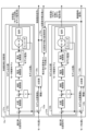
- FIG. 12 is a diagram showing a configuration example of the control system 40a according to the second embodiment.
- the control system 40a includes a controller 10a and motor control devices 20a and 20b.
- the controller 10a is a host control device connected to the motor control devices 20a and 20b.
- a mechanical system 30a is connected to the motor control device 20a, and a mechanical system 30b is connected to the motor control device 20b.
- the motor control device 20a includes a position deviation calculator 21a, a position controller 22a, a speed calculator 23a, a speed deviation calculator 24a, a speed controller 25a, and a current limiter 26a. , and a current control unit 27a.
- the motor control device 20b includes a position deviation calculator 21b, a position controller 22b, a speed calculator 23b, a speed deviation calculator 24b, a speed controller 25b, a current limiter 26b, and a current controller 27b.
- the mechanical system 30a includes a motor 31a, a load 32a, and an encoder 33a.
- the mechanical system 30b also includes a motor 31b, a load 32b, and an encoder 33b. Since the motor control devices 20a and 20b have the same configuration as the motor control device 20 of the first embodiment, detailed description thereof will be omitted. Since the mechanical systems 30a and 30b have the same configuration as the mechanical system 30 of the first embodiment, detailed description thereof will be omitted.
- the controller 10a includes a program analysis section 11, a pre-correction position command calculation section 12a, an acceleration correction calculation section 13a, and position command calculation sections 14a and 14b.
- the pre-correction position command calculator 12a, the acceleration correction calculator 13a, and the position command calculators 14a and 14b constitute a position command generator 15a.
- the program analysis unit 11 performs the same operation as the program analysis unit 11 of Embodiment 1 shown in FIG.
- the pre-correction position command calculation unit 12a generates interpolation data based on the analysis data acquired from the program analysis unit 11, and generates pre-correction position commands a and b for accelerating and decelerating the motors 31a and 31b based on the interpolation data. to calculate The pre-correction position command calculator 12a calculates pre-correction position commands a and b for the two motors 31a and 31b. The operation is the same as that of the pre-correction position command calculator 12 of the first embodiment shown in FIGS. Therefore, a detailed description of the operation of the pre-correction position command calculator 12a is omitted.
- the acceleration correction calculation unit 13a uses the pre-correction position commands a and b obtained from the pre-correction position command calculation unit 12a, the motor position a obtained from the encoder 33a, and the motor position b obtained from the encoder 33b to calculate the pre-correction position A position command correction value a for correcting the command a is calculated, and a position command correction value b for correcting the pre-correction position command b is calculated.
- FIG. 13 is a diagram showing a configuration example of the acceleration correction calculation section 13a included in the controller 10a according to the second embodiment.
- the acceleration correction calculation unit 13a includes model output units 131a and 131b, model position deviation calculation units 133a and 133b, comparison units 134a and 134b, and a position command correction value calculation unit 135a.
- the model output unit 131a holds a motor control model 132a.
- the model output unit 131b holds a motor control model 132b.
- the operations of the model output units 131a and 131b, the model position deviation calculation units 133a and 133b, and the comparison units 134a and 134b are similar to those of the model output unit 131, the model position deviation calculation unit 133, and the comparison units of the first embodiment shown in FIG. 134, detailed description thereof will be omitted.
- the position command correction value calculation unit 135a calculates position command correction values a and b for the pre-correction position commands a and b. At this time, the position command correction value calculation section 135a calculates the position command correction values a and b by ORing the control saturation signals a and b output from the comparison sections 134a and 134b. The position command correction value calculation unit 135a calculates 1 of the post-correction position commands a and b for all the motors 31a and 31b when there is saturation of the control input in at least one of the plurality of motors 31a and 31b. Position command correction values a and b for correcting the pre-correction position commands a and b are calculated and output so that the amount of change for each control cycle is reduced.
- the configuration corresponding to the position command correction value calculation unit 135a takes the logical sum of three or more control saturation signals, thereby realizing the same control as in the present embodiment.
- the controller 10a is connected to a plurality of motor controllers 20a, 20b that supply current to different motors 31a, 31b to control their operation, and the plurality of motors 31a, 31b are interpolated.
- the acceleration correction calculation unit 13a turns ON the control saturation signal for one of the motors 31a and 31b and outputs it, the corrected command acceleration, which is the corrected acceleration, is obtained while maintaining the interpolating operation between the motors 31a and 31b.
- Position command correction values for a plurality of motors 31a and 31b that perform interpolation operations are output so as to decrease.
- the acceleration correction calculation unit 13a turns ON the control saturation signals while maintaining the interpolating operation of the motors 31a and 31b.
- the position command correction values for the plurality of motors 31a and 31b that perform interpolation operations are changed so as to increase from the post-correction command acceleration at the time of output.
- the hardware configuration of the controller 10a of the second embodiment is the same as the hardware configuration of the controller 10 of the first embodiment shown in FIG.
- the controller 10a is connected to the plurality of motor control devices 20a and 20b, and even when the plurality of motors 31a and 31b perform interpolation operations, the motors 31a and 31b It is possible to suppress the deterioration of the control performance due to the saturation of the control input while maintaining the path of the driven object, and obtain the same effect as in the first embodiment.
- Embodiment 3 In the third embodiment, a case will be described in which the motor control device outputs a current limit signal indicating that the current is being limited when the current is being limited in response to the current command.
- FIG. 14 is a diagram showing a configuration example of a control system 40c according to the third embodiment.
- the control system 40c includes a controller 10c and a motor control device 20c.
- the controller 10c is a host control device connected to the motor control device 20c.
- a mechanical system 30 is connected to the motor control device 20c.
- the motor control device 20c includes a position deviation calculator 21, a position controller 22, a speed calculator 23, a speed deviation calculator 24, a speed controller 25, and a current limiter 26c. , and a current control unit 27 .
- the current limiting section 26c has the same function as the current limiting section 26 of the first embodiment shown in FIG. It has the function to Controlled saturation can be considered during current limiting.
- the current limiter 26c turns ON the current limit signal and outputs it when the current limit is performed, and turns OFF the current limit signal when the current limit is not performed.
- the controller 10c includes a program analysis unit 11, a pre-correction position command calculation unit 12c, an acceleration correction calculation unit 13c, and a position command calculation unit 14.
- the pre-correction position command calculator 12c, the acceleration correction calculator 13c, and the position command calculator 14 constitute a position command generator 15c.
- FIG. 15 is a diagram showing a configuration example of the acceleration correction calculation section 13c included in the controller 10c according to the third embodiment.
- the acceleration correction calculation unit 13c includes a model output unit 131, a model position deviation calculation unit 133, a comparison unit 134, a position command correction value calculation unit 135c, and a logical sum calculation unit 136.
- the logical sum calculation unit 136 calculates the logical sum of the control saturation signal obtained from the comparison unit 134 and the current limiting signal obtained from the current limiting unit 26c of the motor control device 20c.
- the OR operation unit 136 turns ON the control saturation signal c when at least one of the control saturation signal and the current limit signal is ON, and outputs the control saturation signal c when both the control saturation signal and the current limit signal are OFF. is turned off.
- the position command correction value calculation unit 135c acquires a different signal from the position command correction value calculation unit 135 of the first embodiment. The operation is the same as that of the correction value calculation unit 135 .
- the acceleration correction calculation unit 13c acquires the current limit signal indicating whether or not the current command, which is the control input to the motor 31 from the motor control device 20c, is equal to or greater than a specified value, and the current command is determined.
- the control saturation signal c is turned ON and output.
- the acceleration correction calculation unit 13c acquires a current limit signal indicating that the current command is less than a specified value and when the model position deviation is less than a specified threshold value, the acceleration correction calculation unit 13c turns off the control saturation signal c and outputs it. .
- the pre-correction position command calculation unit 12c acquires a different signal from the pre-correction position command calculation unit 12 of the first embodiment. The operation is the same as that of the position command calculation unit 12 .
- the hardware configuration of the controller 10c of the third embodiment is the same as the hardware configuration of the controller 10 of the first embodiment shown in FIG.
- the controller 10c uses the current limit signal to determine control saturation.
- the controller 10c can detect the saturation of the control input earlier than the control saturation signal turns ON due to the expansion of the model position deviation under the torque saturation condition.
- Embodiment 4 a learning device and an inference device that machine-learn the machine model 123 will be described.
- the mechanical model 123 here is composed of a motor characteristic model 124 and a load model 125.
- the acceleration/deceleration processing unit 122 mainly shown in FIG. It is used to calculate a pre-correction position command for acceleration/deceleration driving.
- the motor characteristic model 124 is mainly a torque-speed characteristic, and is used to calculate the torque that can be output according to the supply voltage, operating speed, and the like.
- the load model 125 is used to calculate the load inertia J for the motor 31 mainly from work information, friction torque T1, unbalanced load torque T2, and other information.
- FIG. 16 is a diagram showing a configuration example of a learning device 70 applied to the controller 10 according to the fourth embodiment.
- the learning device 70 includes a data acquisition unit 71 , a model generation unit 72 , and a learned model storage unit 73 .
- the model is a machine model 123 mainly in the acceleration/deceleration processing unit 122 shown in FIG. be.
- the learned model storage unit 73 is outside the learning device 70 in FIG. 16 , the learned model storage unit 73 may be included inside the learning device 70 .
- the data acquisition unit 71 acquires the acquired information and the machine state as learning data from the controller 10 .
- the acquired information includes the control saturation signal of the control input, the state quantity indicating the operating state of at least one of the controller 10, the motor control device 20, and the motor 31, program information, and workpiece information.
- the machine state includes motor characteristics, load inertia J, friction torque T1, and unbalanced load torque T2.
- the model generating unit 72 learns the obtained information using the obtained information output from the data obtaining unit 71 and the learning data created based on the combination of the machine states that are the teacher data. That is, the model generator 72 generates a learned model for inferring the optimum load model 125 included in the machine model 123 from the acquired information of the controller 10 and the machine state.
- the learning data is data in which the obtained information and the machine state are associated with each other.
- the learning algorithm used by the model generation unit 72 can use known algorithms such as supervised learning, unsupervised learning, and reinforcement learning. As an example, a case where a neural network is applied will be described.
- the model generator 72 learns the machine model 123 by so-called supervised learning, for example, according to the neural network model.
- supervised learning refers to a method of inferring a result from an input by giving a set of input and result (label) data to the learning device 70 to learn features in the learning data.
- a neural network consists of an input layer consisting of multiple neurons, an intermediate layer (hidden layer) consisting of multiple neurons, and an output layer consisting of multiple neurons.
- the intermediate layer may be one layer, or two or more layers.
- FIG. 17 is a diagram schematically showing an example of a neural network used in model generation section 72 of learning device 70 according to the fourth embodiment.
- the neural network learns the machine model 123 by so-called supervised learning according to learning data created based on a combination of the acquired information acquired by the data acquisition unit 71 and the teacher data.
- the neural network learns by adjusting the weights W1 and W2 so that the obtained information is input to the input layer and the result output from the output layer approaches the teacher data.
- the model generation unit 72 generates and outputs a learned model by executing the above learning.
- the learned model storage unit 73 stores the learned model output from the model generation unit 72.
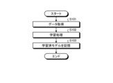
- FIG. 18 is a flow chart showing learning processing of the learning device 70 according to the fourth embodiment.
- the data acquisition unit 71 acquires the acquired information and the machine state as data (step S101). Although the data acquisition unit 71 acquires the acquired information and the machine state at the same time, the present invention is not limited to this. Since the data acquisition unit 71 only needs to input the acquired information and the machine state in association with each other, the acquired information and the machine state may be acquired at different timings.
- the model generation unit 72 performs learning processing (step S102). Specifically, the model generation unit 72 learns the machine model 123 by so-called supervised learning according to learning data created based on a combination of the acquired information acquired by the data acquisition unit 71 and the machine state. Generate a finished model.
- the learned model storage unit 73 stores the learned model generated by the model generation unit 72 (step S103).
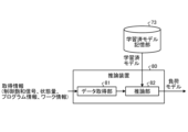
- FIG. 19 is a diagram showing a configuration example of an inference device 80 applied to the controller 10 according to the fourth embodiment.
- the inference device 80 includes a data acquisition unit 81 and an inference unit 82 .
- the inference unit 82 here corresponds to the acceleration/deceleration processing unit 122 shown in FIG. 2 and outputs a pre-correction position command based on the learned machine model 123 .
- the data acquisition unit 81 acquires acquisition information.
- the acquired information includes the control saturation signal of the control input, the state quantity indicating the operating state of at least one of the controller 10, the motor control device 20, and the motor 31, program information, and workpiece information.
- the inference unit 82 uses the learned model stored in the learned model storage unit 73 to infer the load model 125 included in the machine model 123 from the acquired information acquired by the data acquisition unit 81 . That is, the inference unit 82 can infer and output the load model 125 included in the machine model 123 inferred from the acquired information by inputting the acquired information acquired by the data acquisition unit 81 into the learned model. can.
- the machine model 123 is output using the learned model learned by the model generation unit 72 of the learning device 70 applied to the controller 10.
- a learned model may be obtained from the learning device 70 that is used, and the machine model 123 may be output based on this learned model.
- FIG. 20 is a flowchart showing inference processing of the inference device 80 according to the fourth embodiment.
- the data acquisition unit 81 acquires acquisition information as data (step S111).
- the inference unit 82 inputs the acquired information to the learned model stored in the learned model storage unit 73 (step S112).
- the inference unit 82 obtains the machine model 123 by inputting acquired information into the learned model.
- the inference unit 82 outputs the machine model 123 obtained by the learned model to the controller 10 as data (step S113).
- the controller 10 outputs a pre-correction position command based on the acquired machine model 123 (step S114).
- the learning device 70 and the reasoning device 80 can output the program information and the factors that change in the work state as the machine model 123 based on the information that can be obtained from the control system 40, making it possible to easily predict the operation. Become.
- supervised learning is applied to the learning algorithm used by the model generation unit 72
- the present invention is not limited to this.
- reinforcement learning unsupervised learning, semi-supervised learning, and the like as learning algorithms.
- the model generation unit 72 may learn the machine model 123 according to learning data created for a plurality of controllers 10 .
- the model generation unit 72 may acquire learning data from a plurality of controllers 10 used in the same area, or learning data collected from a plurality of controllers 10 operating independently in different areas. may be used to learn the machine model 123 .
- the model generation unit 72 may add the controller 10 from which the learning data is to be collected to the target in the middle, or remove it from the target in the middle.
- the learning device 70 that has learned the machine model 123 for a certain controller 10 may be applied to another controller 10 to relearn and update the machine model 123 for the other controller 10 .
- model generation unit 72 deep learning that learns to extract the feature amount itself can also be used, and other known methods such as genetic programming, functional logic programming, Machine learning may be performed according to support vector machines and the like.
- the learning device 70 and the reasoning device 80 are used to learn the machine model 123 of the controller 10, for example, they may be connected to the controller 10 via a network and may be devices separate from the controller 10. good. Also, the learning device 70 and the reasoning device 80 may be built in the controller 10 . Furthermore, learning device 70 and reasoning device 80 may reside on a cloud server.
- FIG. 21 is a diagram showing an example in which learning device 70 and reasoning device 80 are installed outside controller 10 in the fourth embodiment.
- FIG. 22 is a diagram showing an example in which the learning device 70 and the reasoning device 80 are installed inside the controller 10 in the fourth embodiment.
- a network may exist between controller 10 and learning device 70 and reasoning device 80 .
- the learning device 70 and the reasoning device 80 may exist on a cloud server. 21 and 22, it is assumed that the learned model storage unit 73 is included in the learning device 70.
- FIG. 21 and 22 it is assumed that the learned model storage unit 73 is included in the learning device 70.
- the controller 10 may update the machine model 123 by the method of the first embodiment, or update the machine model 123 using the learning device 70 and the inference device 80 as in the fourth embodiment. good too.
- the learning device 70 and the reasoning device 80 are applied to the controller 10 has been described, the present invention is not limited to this. It is also possible to apply the learning device 70 and the reasoning device 80 to the controllers 10a and 10c.
Landscapes
- Engineering & Computer Science (AREA)
- Power Engineering (AREA)
- Health & Medical Sciences (AREA)
- Artificial Intelligence (AREA)
- Computer Vision & Pattern Recognition (AREA)
- Evolutionary Computation (AREA)
- Medical Informatics (AREA)
- Software Systems (AREA)
- Physics & Mathematics (AREA)
- General Physics & Mathematics (AREA)
- Automation & Control Theory (AREA)
- Control Of Electric Motors In General (AREA)
Abstract
Description
図1は、実施の形態1に係る制御システム40の構成例を示す図である。制御システム40は、コントローラ10と、モータ制御装置20と、を備える。本実施の形態において、コントローラ10は、制御入力の飽和による制御性能の劣化を抑制すること、およびモータ制御装置20に対する位置指令を生成する際に使用する機械モデルを飽和状況に基づいて更新することを特徴とする。以下、それぞれの特徴について説明する。まず、制御入力の飽和による制御性能の劣化を抑制することについて説明する。ここで、制御入力の飽和とは、予め設定された制御入力制限を超えることを意味する。
実施の形態1では、コントローラ10に接続されるモータ制御装置20が1つの場合について説明した。ここで、上位制御装置であるコントローラには、複数のモータを同時に制御できるものがある。ただし、コントローラが複数のモータを同時に補間制御する場合、個別に補正を実施するとモータ同士の補間を取ることができなくなってしまう。実施の形態2では、コントローラに接続されるモータ制御装置が複数あり、コントローラが複数のモータを同時に制御する場合について説明する。
実施の形態3では、モータ制御装置が、電流指令に対して電流制限中の場合に電流制限中であることを示す電流制限信号を出力する場合について説明する。
実施の形態4では、機械モデル123を機械学習する学習装置および推論装置について説明する。ここでの機械モデル123は、モータ特性モデル124および負荷モデル125で構成されており、主に図2に示す加減速処理部122で、補間データに基づいてモータ31が出力可能なトルクの範囲で加減速駆動させるための補正前位置指令の演算に用いられる。モータ特性モデル124は、主にトルク-速度特性であり、供給電圧、動作速度などに応じて出力可能なトルクの算出に用いられる。負荷モデル125は、主にワーク情報、摩擦トルクT1、偏荷重トルクT2などの情報から、モータ31に対する負荷イナーシャJの算出に用いられる。
図16は、実施の形態4に係るコントローラ10に適用される学習装置70の構成例を示す図である。学習装置70は、データ取得部71と、モデル生成部72と、学習済モデル記憶部73と、を備える。ここでのモデルとは、主に図2に示す加減速処理部122にある、モータ31が出力可能なトルクの範囲で加減速駆動させるための補正前位置指令の演算に用いられる機械モデル123である。なお、図16では、学習済モデル記憶部73が学習装置70の外部にあるが、学習済モデル記憶部73を学習装置70の内部に含めてもよい。
図19は、実施の形態4に係るコントローラ10に適用される推論装置80の構成例を示す図である。推論装置80は、データ取得部81と、推論部82と、を備える。ここでの推論部82は、図2に示す加減速処理部122に相当し、学習した機械モデル123に基づいて、補正前位置指令を出力する。
Claims (16)
- モータに電流を供給して動作を制御するモータ制御装置に対して位置指令を出力するコントローラであって、
前記モータの動作によって駆動する駆動対象の経路を規定する動作プログラムを解析し、解析データを出力するプログラム解析部と、
前記モータが出力可能な加速度を算出する機械モデルを有し、前記解析データおよび前記機械モデルに基づいて前記位置指令を生成し、前記モータに対する制御入力が予め設定された制御入力制限を超えて飽和した場合は前記機械モデルを更新する位置指令生成部と、
を備えることを特徴とするコントローラ。 - 前記位置指令生成部は、前記モータに対する制御入力が前記飽和したか否かを判定し、前記制御入力が前記飽和したと判定した場合は、前記飽和したときの前記コントローラおよび前記モータ制御装置および前記モータのうち少なくとも1つの動作状態を示す状態量に基づいて、前記機械モデルを更新する、
ことを特徴とする請求項1に記載のコントローラ。 - 前記位置指令生成部は、
前記モータが出力可能な加速度を算出する機械モデルを有し、前記解析データおよび前記機械モデルに基づいて、補正前位置指令を演算する補正前位置指令演算部と、
前記モータに対する制御入力が前記飽和したか否かを判定し、前記制御入力が前記飽和したと判定した場合は制御飽和信号をONにして出力し、前記制御入力が前記飽和していないと判定した場合は前記制御飽和信号をOFFにして出力し、さらに前記制御飽和信号に基づいて、前記補正前位置指令を補正するための位置指令補正値を演算する加速度補正演算部と、
前記補正前位置指令と前記位置指令補正値とを用いて前記位置指令を演算する位置指令演算部と、
を備え、
前記補正前位置指令演算部は、取得した前記制御飽和信号がONの場合、前記制御飽和信号がONのときの前記コントローラおよび前記モータ制御装置および前記モータのうち少なくとも1つの動作状態を示す状態量に基づいて、前記機械モデルを更新する、
ことを特徴とする請求項1または2に記載のコントローラ。 - 前記加速度補正演算部は、前記補正前位置指令に基づいて前記モータ制御装置が前記モータを制御した場合のモデル位置を生成し、前記モデル位置と検出された前記モータのモータ位置との偏差であるモデル位置偏差が規定された閾値以上の場合、前記制御入力が前記飽和したと判定して前記制御飽和信号をONにして出力し、前記モデル位置偏差が前記閾値未満の場合、前記制御入力が前記飽和していないと判定して前記制御飽和信号をOFFにして出力する、
ことを特徴とする請求項3に記載のコントローラ。 - 前記加速度補正演算部は、前記モータ制御装置から前記モータへの制御入力である電流指令が規定された値以上か否かを示す電流制限信号を取得し、前記電流指令が前記規定された値以上であることを示す前記電流制限信号を取得した場合は前記制御飽和信号をONにして出力し、前記電流指令が前記規定された値未満であることを示す前記電流制限信号を取得した場合かつ前記モデル位置偏差が規定された閾値未満の場合は前記制御飽和信号をOFFにして出力する、
ことを特徴とする請求項4に記載のコントローラ。 - 前記加速度補正演算部は、前記制御飽和信号をONにして出力する場合は補正後の加速度である補正後指令加速度が減少するように前記補正前位置指令を補正する前記位置指令補正値を出力し、その後、前記制御飽和信号をOFFにして出力する場合は前記制御飽和信号をONにして出力したときの前記補正後指令加速度から増加するように前記位置指令補正値を変更する、
ことを特徴とする請求項3から5のいずれか1つに記載のコントローラ。 - 前記補正前位置指令演算部は、取得した前記制御飽和信号がOFFであり、かつ前記機械モデルから算出されたモータトルクとモータ電流から算出されたモータトルクとの偏差であるトルク偏差が規定された値以上の場合、前記状態量に基づいて、前記機械モデルを更新する、
ことを特徴とする請求項3から6のいずれか1つに記載のコントローラ。 - 前記補正前位置指令演算部は、前記機械モデルとしてモータ特性モデルおよび負荷モデルを有し、前記機械モデルとして前記負荷モデルを更新する、
ことを特徴とする請求項7に記載のコントローラ。 - 前記補正前位置指令演算部は、前記機械モデルとしてモータ特性モデルおよび負荷モデルを有し、取得した前記制御飽和信号がONのときにモータ電流が規定された値以上の場合、前記制御飽和信号がONのときの前記状態量に基づいて前記負荷モデルを更新し、取得した前記制御飽和信号がONのときに前記モータ電流が規定された値未満の場合、前記制御飽和信号がONのときの前記状態量に基づいて前記モータ特性モデルを更新する、
ことを特徴とする請求項3から7のいずれか1つに記載のコントローラ。 - 前記状態量は、モータ位置、前記モータ制御装置の駆動対象である機械系の機械端位置、モータ速度、前記機械系の機械端速度、モータ加速度、前記機械系の機械端加速度、モータ電流、トルク情報、前記加速度補正演算部で算出されるモデル位置、負荷イナーシャ推定値、および前記モータへの供給電圧のうち少なくとも1つを含む、
ことを特徴とする請求項3から8のいずれか1つに記載のコントローラ。 - 各々が異なる前記モータに電流を供給して動作を制御する複数の前記モータ制御装置に接続され、複数の前記モータが補間されて制御され、
前記加速度補正演算部は、何れかの前記モータについての前記制御飽和信号をONにして出力する場合、前記モータ同士の補間動作を維持しつつ補正後の加速度である補正後指令加速度が減少するように、補間動作する複数の前記モータに対する位置指令補正値を出力し、その後、補間動作する複数の前記モータについての前記制御飽和信号をOFFにして出力する場合、前記モータ同士の補間動作を維持しつつ前記制御飽和信号をONにして出力したときの前記補正後指令加速度から増加するように、補間動作する複数の前記モータに対する位置指令補正値を変更する、
ことを特徴とする請求項3から10のいずれか1つに記載のコントローラ。 - 前記制御飽和信号、前記状態量、前記動作プログラムのプログラム情報、およびワーク情報を含む取得情報と、モータ特性、負荷イナーシャ、摩擦トルク、および偏荷重トルクを含む教師データと、を学習用データとして取得するデータ取得部と、
前記学習用データを用いて、前記取得情報から、前記機械モデルに含まれる負荷モデルを推論するための学習済モデルを生成するモデル生成部と、
を備える学習装置、
を備えることを特徴とする請求項3から11のいずれか1つに記載のコントローラ。 - 前記制御飽和信号、前記状態量、前記動作プログラムのプログラム情報、およびワーク情報を取得情報として取得するデータ取得部と、
前記機械モデルに含まれる負荷モデルを推論するための学習済モデルを用いて、前記データ取得部で取得された前記取得情報から負荷モデルを推論する推論部と、
を備える推論装置、
を備えることを特徴とする請求項3から12のいずれか1つに記載のコントローラ。 - 請求項1から13のいずれか1つに記載のコントローラと、
前記コントローラから取得した位置指令に基づいてモータの位置制御を行うモータ制御装置と、
を備えることを特徴とする制御システム。 - モータに電流を供給して動作を制御するモータ制御装置に対して位置指令を出力するコントローラから、前記モータに対する制御入力が予め設定された制御入力制限を超えて飽和したか否かを示す制御飽和信号、前記コントローラおよび前記モータ制御装置および前記モータのうち少なくとも1つの動作状態を示す状態量、前記コントローラに入力される動作プログラムのプログラム情報、およびワーク情報を含む取得情報と、モータ特性、負荷イナーシャ、摩擦トルク、および偏荷重トルクを含む教師データと、を学習用データとして取得するデータ取得部と、
前記学習用データを用いて、前記取得情報から、前記コントローラが有する機械モデルに含まれる負荷モデルを推論するための学習済モデルを生成するモデル生成部と、
を備えることを特徴とする学習装置。 - モータに電流を供給して動作を制御するモータ制御装置に対して位置指令を出力するコントローラから、前記モータに対する制御入力が予め設定された制御入力制限を超えて飽和したか否かを示す制御飽和信号、前記コントローラおよび前記モータ制御装置および前記モータのうち少なくとも1つの動作状態を示す状態量、前記コントローラに入力される動作プログラムのプログラム情報、およびワーク情報を取得情報として取得するデータ取得部と、
前記コントローラが有する機械モデルに含まれる負荷モデルを推論するための学習済モデルを用いて、前記データ取得部で取得された前記取得情報から負荷モデルを推論する推論部と、
を備えることを特徴とする推論装置。
Priority Applications (5)
| Application Number | Priority Date | Filing Date | Title |
|---|---|---|---|
| CN202180098399.XA CN117378139B (zh) | 2021-12-13 | 2021-12-13 | 控制器、控制系统 |
| PCT/JP2021/045769 WO2023112082A1 (ja) | 2021-12-13 | 2021-12-13 | コントローラ、制御システム、学習装置および推論装置 |
| CN202411970148.8A CN119766063A (zh) | 2021-12-13 | 2021-12-13 | 学习装置及推断装置 |
| JP2022519601A JP7106038B1 (ja) | 2021-12-13 | 2021-12-13 | コントローラ、制御システム、学習装置および推論装置 |
| DE112021007575.6T DE112021007575T5 (de) | 2021-12-13 | 2021-12-13 | Steuerung, Steuerungssystem, Lernvorrichtung und Inferenzvorrichtung |
Applications Claiming Priority (1)
| Application Number | Priority Date | Filing Date | Title |
|---|---|---|---|
| PCT/JP2021/045769 WO2023112082A1 (ja) | 2021-12-13 | 2021-12-13 | コントローラ、制御システム、学習装置および推論装置 |
Publications (1)
| Publication Number | Publication Date |
|---|---|
| WO2023112082A1 true WO2023112082A1 (ja) | 2023-06-22 |
Family
ID=82556746
Family Applications (1)
| Application Number | Title | Priority Date | Filing Date |
|---|---|---|---|
| PCT/JP2021/045769 Ceased WO2023112082A1 (ja) | 2021-12-13 | 2021-12-13 | コントローラ、制御システム、学習装置および推論装置 |
Country Status (4)
| Country | Link |
|---|---|
| JP (1) | JP7106038B1 (ja) |
| CN (2) | CN119766063A (ja) |
| DE (1) | DE112021007575T5 (ja) |
| WO (1) | WO2023112082A1 (ja) |
Citations (3)
| Publication number | Priority date | Publication date | Assignee | Title |
|---|---|---|---|---|
| JPH10138186A (ja) * | 1996-11-01 | 1998-05-26 | Toyota Motor Corp | 物理系の制御方法および装置 |
| JP2018173777A (ja) * | 2017-03-31 | 2018-11-08 | ファナック株式会社 | 機械学習装置、サーボ制御装置、サーボ制御システム、及び機械学習方法 |
| JP2019181635A (ja) * | 2018-04-12 | 2019-10-24 | ファナック株式会社 | 情報処理装置及び情報処理方法 |
Family Cites Families (2)
| Publication number | Priority date | Publication date | Assignee | Title |
|---|---|---|---|---|
| JP5388604B2 (ja) | 2009-01-29 | 2014-01-15 | 三菱電機株式会社 | モータ駆動制御装置 |
| JP6697491B2 (ja) * | 2018-01-25 | 2020-05-20 | ファナック株式会社 | 機械学習装置、サーボモータ制御装置、サーボモータ制御システム、及び機械学習方法 |
-
2021
- 2021-12-13 DE DE112021007575.6T patent/DE112021007575T5/de active Pending
- 2021-12-13 WO PCT/JP2021/045769 patent/WO2023112082A1/ja not_active Ceased
- 2021-12-13 CN CN202411970148.8A patent/CN119766063A/zh active Pending
- 2021-12-13 JP JP2022519601A patent/JP7106038B1/ja active Active
- 2021-12-13 CN CN202180098399.XA patent/CN117378139B/zh active Active
Patent Citations (3)
| Publication number | Priority date | Publication date | Assignee | Title |
|---|---|---|---|---|
| JPH10138186A (ja) * | 1996-11-01 | 1998-05-26 | Toyota Motor Corp | 物理系の制御方法および装置 |
| JP2018173777A (ja) * | 2017-03-31 | 2018-11-08 | ファナック株式会社 | 機械学習装置、サーボ制御装置、サーボ制御システム、及び機械学習方法 |
| JP2019181635A (ja) * | 2018-04-12 | 2019-10-24 | ファナック株式会社 | 情報処理装置及び情報処理方法 |
Also Published As
| Publication number | Publication date |
|---|---|
| DE112021007575T5 (de) | 2024-02-22 |
| CN117378139B (zh) | 2025-01-03 |
| JPWO2023112082A1 (ja) | 2023-06-22 |
| JP7106038B1 (ja) | 2022-07-25 |
| CN117378139A (zh) | 2024-01-09 |
| CN119766063A (zh) | 2025-04-04 |
Similar Documents
| Publication | Publication Date | Title |
|---|---|---|
| CN114655248A (zh) | 自动驾驶车辆的横向控制方法、装置及车辆 | |
| US9207654B2 (en) | Servo controller | |
| US5144549A (en) | Time delay controlled processes | |
| US6037736A (en) | Apparatus for determination of control constant | |
| JP6469320B1 (ja) | サーボ制御装置 | |
| JP6740279B2 (ja) | 調整装置及び調整方法 | |
| TWI440295B (zh) | 馬達控制裝置 | |
| JP2019063960A (ja) | 熱変位補正システム | |
| JP2019063959A (ja) | 熱変位補正システム | |
| CN116829440A (zh) | 机动车辆车道保持辅助系统 | |
| KR20130017403A (ko) | 액추에이터 제어 장치 및 방법 | |
| CN116635802B (zh) | 数控装置 | |
| JP4453526B2 (ja) | サーボ制御装置 | |
| JP6646025B2 (ja) | 制御装置及び機械学習装置 | |
| JP2002091570A (ja) | サーボ制御方法 | |
| JP7106038B1 (ja) | コントローラ、制御システム、学習装置および推論装置 | |
| JP2014174842A (ja) | S字加減速制御プログラム、動作制御プログラム、記録媒体、コントローラ、s字加減速制御演算方法およびワーク動作制御システム | |
| CN116830118A (zh) | 电动助力转向中的马达控制 | |
| KR100222763B1 (ko) | 로봇의 위치제어용 선형출력 제어장치 및 방법 | |
| JP3582541B2 (ja) | スライディングモード制御による位置決め制御方法 | |
| Cheong et al. | Joint tracking controller for multi‐link flexible robot using disturbance observer and parameter adaptation scheme | |
| Das et al. | Fuzzy Fractional Order PID Controller Design for Single Link Robotic Arm Manipulator | |
| JP7558456B1 (ja) | モータ制御装置およびモータ制御方法 | |
| JP2881873B2 (ja) | デジタル適応制御装置 | |
| Zhang et al. | Adaptive Extended State Observer-Based Tracking Control for PMSM Drive Systems With Uncertainties and Disturbances |
Legal Events
| Date | Code | Title | Description |
|---|---|---|---|
| WWE | Wipo information: entry into national phase |
Ref document number: 2022519601 Country of ref document: JP |
|
| 121 | Ep: the epo has been informed by wipo that ep was designated in this application |
Ref document number: 21968005 Country of ref document: EP Kind code of ref document: A1 |
|
| WWE | Wipo information: entry into national phase |
Ref document number: 202180098399.X Country of ref document: CN |
|
| WWE | Wipo information: entry into national phase |
Ref document number: 112021007575 Country of ref document: DE |
|
| 122 | Ep: pct application non-entry in european phase |
Ref document number: 21968005 Country of ref document: EP Kind code of ref document: A1 |
|
| WWG | Wipo information: grant in national office |
Ref document number: 202180098399.X Country of ref document: CN |