WO2023112080A1 - 試薬保管庫、および自動分析装置 - Google Patents
試薬保管庫、および自動分析装置 Download PDFInfo
- Publication number
- WO2023112080A1 WO2023112080A1 PCT/JP2021/045763 JP2021045763W WO2023112080A1 WO 2023112080 A1 WO2023112080 A1 WO 2023112080A1 JP 2021045763 W JP2021045763 W JP 2021045763W WO 2023112080 A1 WO2023112080 A1 WO 2023112080A1
- Authority
- WO
- WIPO (PCT)
- Prior art keywords
- reagent
- reagent storage
- automatic analyzer
- identification code
- disk
- Prior art date
Links
Images


Classifications
-
- G—PHYSICS
- G01—MEASURING; TESTING
- G01N—INVESTIGATING OR ANALYSING MATERIALS BY DETERMINING THEIR CHEMICAL OR PHYSICAL PROPERTIES
- G01N35/00—Automatic analysis not limited to methods or materials provided for in any single one of groups G01N1/00 - G01N33/00; Handling materials therefor
Definitions
- the present invention relates to an automatic analyzer that analyzes samples such as blood and urine, and a reagent storage.
- Patent Document 1 describes an automatic analyzer that can use a reagent container that has an ID such as a barcode attached to the upper surface or the lower surface of the reagent container, or both.
- information such as the type of reagent is recorded on information recording media such as barcodes, which are read and used for quality control of testing.
- the location where the information recording medium is attached is not limited to the top or side of the reagent container, but is sometimes attached to the bottom.
- the information recording medium is preferably provided on the upper surface of the reagent container, and it is difficult to read the information recording medium provided on the side or bottom of the reagent container.
- the present invention includes a plurality of means for solving the above problems.
- a plurality of reagent containers each holding a reagent therein and having an identification code in which information about the reagent is recorded are provided.
- a reagent disk to be installed a main body for housing the reagent disk inside, a lid for the reagent disk covering the upper surface side of the main body, a rotation mechanism for rotating the reagent disk, a reading device for reading the identification code
- the reagent storage includes a guide for moving the reading device between the side and bottom of the reagent container installed on the reagent disk.
- the present invention it is possible to use the reagent container provided with the information recording medium on the side or the bottom without distinguishing between them, and it is possible to perform the inspection using a more correct reagent than in the past. Problems, configurations and effects other than those described above will be clarified by the following description of the embodiments.
- FIG. 1 is a diagram showing a schematic configuration of an automatic analyzer according to Example 1 of the present invention
- FIG. 3 shows an identification code on the side of a reagent container
- FIG. 4 shows the identification code on the bottom of the reagent container.
- 4 is a diagram showing a schematic configuration of a reagent storage of the automatic analyzer according to Example 1.
- FIG. 4 is a diagram showing a schematic cross-sectional configuration of a reagent storage of the automatic analyzer according to Example 1.
- FIG. 4 is a diagram showing details of a curve guide, a block, and a reading device in a reagent storage of the automatic analyzer according to Example 1.
- FIG. 4 shows a reagent information reading workflow of the automatic analyzer according to Example 1.
- FIG. 11 is a diagram showing a schematic cross-sectional configuration of a reagent storage of an automatic analyzer according to Example 4; FIG. 11 shows a reagent information reading workflow of the automatic analyzer according to Example 4.
- FIG. 11 is a diagram showing a schematic cross-sectional configuration of a reagent storage of an automatic analyzer according to Example 4; FIG. 11 shows a reagent information reading workflow of the automatic analyzer according to Example 4.
- Example 1 A first embodiment of a reagent storage and an automatic analyzer of the present invention will be described with reference to FIGS. 1 to 7.
- FIG. 1 A first embodiment of a reagent storage and an automatic analyzer of the present invention will be described with reference to FIGS. 1 to 7.
- FIG. 1 A first embodiment of a reagent storage and an automatic analyzer of the present invention will be described with reference to FIGS. 1 to 7.
- FIG. 1 A first embodiment of a reagent storage and an automatic analyzer of the present invention will be described with reference to FIGS. 1 to 7.
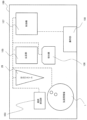
- FIG. 1 is a diagram showing a schematic configuration of an automatic analyzer according to the first embodiment.
- an automatic analyzer 100 is an apparatus for dispensing a specimen and a reagent into a reaction section 105 and measuring the physical properties of a mixed liquid prepared by reacting. It has a system 28, a reagent storage 1, a reaction section 105, a detection section 106, a control section 107, an operation section 108, and the like.
- the specimen installation section 103 has a structure for annularly installing specimen containers (not shown for convenience' sake). During sample dispensing, the sample installation unit 103 rotates to transport the sample container to the access position of the dispensing system 28 .
- the reagent storage 1 is a mechanism for storing reagent containers 14 containing reagents (see FIGS. 2 and 3), and has reagent disks 13 and the like.
- a plurality of reagent installation positions are provided on the reagent disk 13, and are configured so that a plurality of reagent containers 14 can be installed.
- the reagent disc 13 has a rotary drive mechanism, and moves each reagent container 14 to a predetermined position on the circumference by a rotary motion.
- the pipetting system 28 is composed of a rotary drive mechanism, a vertical drive mechanism, and a pipetting probe. Alternatively, it moves between the reagent aspirating position (the position of the dispensing hole 4 ) in the reagent storage 1 and the reagent discharging position in the reaction section 105 to dispense the sample from the sample container or the reagent from the reagent container 14 .
- This pipetting system 28 may be in a form in which a system dedicated to specimens and a system dedicated to reagents are provided separately or in a form in which they are shared, and are not particularly limited.
- the control unit 107 is composed of, for example, a hardware board and a computer, and incorporates a storage device such as a hard disk. In this embodiment, the controller 107 controls the operation of the reader 16 so that the identification code 15 is read when the dispensing system 28 dispenses the reagent. The details will be described later.
- the control unit 107 may be configured as hardware by a dedicated circuit board, or may be configured by software executed by a computer. When configured by hardware, it can be realized by integrating a plurality of arithmetic units for executing processing on a wiring substrate, a semiconductor chip, or a package. When configured by software, it can be realized by installing a high-speed general-purpose CPU in a computer and executing a program for executing desired arithmetic processing. It is also possible to upgrade an existing device with a recording medium in which this program is recorded. These devices, circuits, and computers are connected by a wired or wireless network, and data is transmitted and received as appropriate.
- the operation unit 108 is composed of a display device, which is a display, and input devices such as a mouse and a keyboard.
- FIG. 2 shows the identification code on the side of the reagent container
- FIG. 3 shows the identification code on the bottom of the reagent container.
- Each of the reagent containers 14 shown in FIGS. 2 and 3 is a container having a tubular side surface, holds a reagent therein, and has an identification code 15 in which information about the reagent is recorded. .
- the reagent container 14 shown in FIG. 2 has an identification code 15 formed of a two-dimensional bar code, a one-dimensional bar code, or the like attached to its side surface.
- the identification code 15 stores the container ID for identifying the reagent container 14, the type of reagent, the amount of reagent, the expiration date of the reagent, and other necessary information.
- an identification code 15 composed of a two-dimensional barcode, a one-dimensional barcode, etc. is attached to the bottom surface.
- the shape of the reagent container 14 is tubular as shown in FIGS. 2 and 3
- the shape is not particularly limited, and may be rectangular parallelepiped. Also, by having two or more separated compartments, one tube may hold two or more types of reagents.
- FIG. 4 is a diagram showing a schematic configuration of the reagent storage of the automatic analyzer according to Example 1
- FIG. 5 is a diagram showing a cross-sectional schematic configuration of the reagent storage
- FIG. 6 is a curve guide, a block, and a reader in the reagent storage. It is a diagram showing the details of.
- the reagent storage cabinet 1 includes a reagent disk 13, a main body 3, a lid 2, a fixture 5, a pot 6, a heat insulating material 7, windows 9 and 10, a rotating mechanism, a reading device 16, a curved line. It is composed of a guide 19, a block 17, a timing belt 20, a timing pulley 21, an idler pulley 22, and the like.
- the main body 3 is a container for accommodating the reagent disk 13 inside, and is composed of a heat insulating material 7 for accommodating the cauldron 6 interposed between the main body 3 and the reagent disk 13, and a transparent member for reading the identification code 15. It has one or more windows 9 on the side and one or more windows 10 on the bottom.
- the window 10 is formed on the bottom surface of the substantially disk-shaped main body 3, in the area directly below the portion where the dispensing hole 4 provided in the lid 2 is provided, in the vertical direction as if a part of the main body 3 and the heat insulating material 7 were removed. is provided.
- the window 9 is located on the side surface of the substantially disk-shaped main body 3 and is located on the outer circumferential side of the reagent disk 13 at the location where the dispensing hole 4 provided in the lid 2 is provided. It is provided as if a part of the was removed.
- These windows 9 and 10 are provided on the side surface or the bottom surface of the main body 3, respectively, but may be provided at two or more locations on the side surface or the bottom surface.
- the reader 16 is a device that reads the identification code 15 and is installed on the curve guide 19 so as to read the identification code 15 installed on the reagent disk 13 through the windows 9 and 10 .
- the reader 16 is assumed to have an imaging device such as a CMOS camera, but it is not particularly limited and may be read by oscillating a laser and using its light.
- the curved guide 19 shown in FIGS. 4 to 6 is provided on the outside of the main body 3 of the reagent storage 1, and has a window 10 capable of imaging the bottom surface of the reagent container 14 installed on the reagent disc 13, and a guide 19 of the reagent container 14. It is provided for moving between windows 9 capable of imaging the sides. Movement of the reader 16 between the window 9 and the window 10 is controlled by the controller 107 .
- This curved guide 19 is installed so that the position where the identification code 15 attached to the reagent container 14 installed inside can be seen from the window 9 or the window 10 of the reagent storage 1 is set as a trajectory. It is desirable that the identification code 15 be installed so that the identification code 15 can be confirmed through the window 9 when the identification code 15 is provided on the bottom surface, and through the window 10 when the identification code 15 is provided on the bottom surface.
- the curved guide 19 is preferably arranged so as to linearly connect the windows 9 and 10 when the automatic analyzer 100 is viewed from above in the vertical direction. It is desirable to have arcuate motion guides that are curved when viewed from the vertical direction.
- Block 17 with the reading device 16 attached moves on the curve guide 19 that draws a curve.
- Block 17 can be moved by timing belt 20 .
- the timing belt 20 is moved by a timing pulley 21 and an idler pulley 22 .
- a block 17 may be provided on the belt conveyor, the reading device 16 may be attached to the block 17, and the reading device 16 may be moved.
- reading device 16 and the curve guide 19 are not limited to being arranged outside the main body 3 and may be arranged inside the main body 3 .
- reading devices 16 may be installed within the automatic analyzer 100, it is desirable to have only one reading device 16 in the area near the reagent storage 1.
- the lid 2 covers the top side of the main body 3 and is provided with a dispensing hole 4 for the dispensing system 28 to access the reagent container 14 installed on the reagent disk 13 in the main body 3 .
- the lid 2 is provided with a fixture 5 that prevents the lid 2 from being freely opened after the reagent is placed, and can be opened and closed according to commands from a device such as an electromagnetic lock.
- the rotation mechanism rotates the reagent disk 13, and is composed of a motor 23, pulley 24, belt 25, shaft 26, pedestal 27, and the like.
- a shaft 26 is connected to the central portion of the reagent disk 13 .
- a shaft 26 is driven by a motor 23 via a pulley 24 and a belt 25 to rotate, thereby making it possible to rotate the reagent disk 13 .
- These members are held by a pedestal 27 .
- the method of rotating the reagent disk 13 is not limited to this, and may be rotated by other methods.
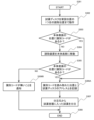
- FIG. 7 shows the reagent information reading workflow of the automatic analyzer according to the first embodiment.
- reading of the identification code 15 starts when the reagent container 14 is started to be loaded into the apparatus, for example, by manual loading by an operator or automatic loading by a reagent container transporting device. (Step 301).
- control unit 107 controls the rotation mechanism so that the position where the reagent container 14 to be read is placed is directly below the dispensing hole 4, which is the first reading position, that is, the positions of the windows 9 and 10. to rotate the reagent disk 13 and stop it (step 302).
- the reader 16 is moved to a position where the reagent container 14 can be photographed through the window 9 on the side of the main body 3 (step 302).
- step 303 If the reading is successful, the process proceeds to step 306A.
- step 304 the reading device 16 is moved to a position where the reagent container 14 can be imaged from the window 10 on the bottom surface of the main body 3 (step 304).
- the identification code 15 provided on the bottom surface of the reagent container 14 installed on the reagent disk 13 is read through the window 10 by the reading device 16, and the identification code 15 is located on the bottom surface, and the reading is successful. (step 305).
- step 306A If the reading is successful, the process proceeds to step 306A, and if the reading fails, the process proceeds to step 306B.
- step 306A When the identification code 15 is successfully read in step 303 or step 305, the address of the reagent disk 13 from which the identification code 15 is read is associated with the reagent information of the installed reagent container 14 (step 306A).
- the dispensing system 28 dispenses from the address of the reagent disk 13 containing the reagent container 14 containing the reagent having the requested reagent information (step 307). Specifically, the dispensing system 28 dispenses the reagent in the reagent container 14 through the dispensing hole 4 in the lid 2 of the reagent storage 1 .
- control unit 107 moves the reading device 16 to the position of the window 9 or window 10 on the side where the reading is successful, and also when dispensing the reagent. It is desirable to read the reagent information and confirm whether or not the correct reagent has been dispensed.
- step 306B the controller 107 is notified that the identification code 15 cannot be read.
- step 308 the workflow is terminated (step 308). If there is an unread reagent container 14 on the reagent disk 13, the processing from step 301 to step 306B is repeated.
- the reagent storage 1 in the automatic analyzer 100 of the first embodiment of the present invention described above holds reagents therein, and a plurality of reagent containers 14 each having an identification code 15 in which reagent information is recorded are installed.
- a curved guide 19 is provided to move the reader 16 between the sides and bottom of the reagent container 14 located at 13 .
- the identification code 15 attached to the reagent container 14 can be recorded in the reader while the lid 2 of the reagent storage 1 is closed. It is possible to suppress measurement failures due to mistakes more strongly than before, and to enable quality control of reagents. Moreover, even if it is not necessary to provide a plurality of readers 16, the reagent containers 14 provided with the identification code 15 for identifying the reagent on the side or the bottom can be used without discrimination.
- the reading device 16 since the reading device 16 reads the identification code 15 when the dispensing system 28 dispenses the reagent, the correct reagent can be reliably dispensed.
- the main body 3 has one or more windows 9 and 10 for reading the identification code 15 on each of its side and bottom surfaces. By reading the identification code 15 through the windows 9 and 10, it is possible to prevent the volume of the main body 3 of the reagent storage 1 from increasing.
- the curved guide 19 is curved when the reagent storage 1 is viewed from the vertical direction.
- the distance can be shortened, and the time required for processing such as reagent registration can be shortened.
- FIG. 8 is a diagram showing a schematic configuration of the reagent storage of the automatic analyzer according to the second embodiment.
- the reagent storage 1A shown in FIG. 8 is different from the reagent storage 1 of Example 1 in that it further includes a cooling device 8 and is provided with a curved guide 19A instead of the curved guide 19.
- the cooling device 8 is composed of a Peltier element or the like in the reagent storage 1 and is thermally connected to the kettle 6 to cool the interior of the kettle 6 .
- the curved guide 19A extends to the upper part of the lid 2 compared to the curved guide 19, and the highest position of the curved guide 19A in the vertical direction is the height position higher than the lid 2, and the standby position of the reading device 16. It has become.
- the reagent storage and the automatic analyzer of Example 2 of the present invention also provide substantially the same effects as the reagent storage and automatic analyzer of Example 1 described above.
- the highest position of the curved guide 19A in the vertical direction is the height position higher than the lid 2, and is the standby position of the reading device 16.
- FIG. 9 is a diagram showing a schematic configuration of the reagent storage of the automatic analyzer according to the third embodiment.
- the reagent storage 1B of this embodiment shown in FIG. 9 differs from the reagent storage 1 of Embodiment 1 in that it further includes a tilt block 18 for the reading device 16 to read the identification code 15 obliquely.
- the distance from the reader 16 to the identification code 15 is 40 mm
- the reader 16 is tilted 15 ⁇ 2° with respect to the identification code 15
- the reflected light from the reagent container 14 will interfere with the reading by the reader 16. Therefore, it is possible to further improve the reading efficiency.
- the reagent storage and the automatic analyzer of Example 3 of the present invention also provide substantially the same effects as the reagent storage and automatic analyzer of Example 1 described above.
- the reading device 16 further includes a tilt block 18 for reading the identification code 15 from an oblique angle, reading errors can be further reduced. Since the angle at which the identification code 15 can be read increases as the number of reading errors decreases, the angle at which the reagent container 14 can be placed on the reagent disk 13 can be increased, thereby enhancing convenience. play.
- tilt block 18 as in this embodiment can also be applied to the reagent storage 1A described in the second embodiment.
- FIG. 10 is a diagram showing a schematic configuration of the reagent storage of the automatic analyzer according to the fourth embodiment
- FIG. 11 is a diagram showing a cross-sectional schematic configuration of the reagent storage
- FIG. 12 is a diagram showing a workflow for reading reagent information.
- the reagent storage 1C of this embodiment shown in FIGS. 10 and 11 is configured such that the curved guide 19C moves the reading device 16 between the outer peripheral side and the inner peripheral side via the bottom surface of the reagent disk 13. It is different from the reagent storage 1 of the first embodiment in that
- the main body 3C of the reagent storage 1C has a window 9A on the inner peripheral surface side in addition to the window 9 on the outer peripheral surface side and the window 10 on the bottom surface.
- steps 1101 to 1105 are the same as steps 301 to 305 shown in FIG. 7, respectively, so details will be omitted.
- the reading device 16 is then moved to a position where the reagent container 14 can be imaged from the window 9A on the inner peripheral surface of the main body 3 (step 1105). 1106).
- the identification code 15 provided on the side surface of the reagent container 14 installed on the reagent disk 13 is read by the reading device 16 through the window 9A. is successful (step 1107). If the reading is successful, the process proceeds to step 1108A. On the other hand, if the reading fails, the process proceeds to step 1108B.
- Steps 1108A to 1110 after that are the same as steps 306A to 308 shown in FIG. 3, respectively, so the details are similarly omitted.
- the reagent storage and the automatic analyzer of Example 4 of the present invention also provide substantially the same effects as the reagent storage and automatic analyzer of Example 1 described above.
- the curved guide 19C reads the identification code attached to the reagent container 14 even on the inner peripheral side of the main body 3 by moving the reading device 16 between the outer peripheral side and the inner peripheral side via the bottom surface of the reagent disk 13 .
- 15 can be read, the angle at which the identification code 15 can be read is increased, so restrictions on the installation orientation of the reagent container 14 can be relaxed when installing the reagent container 14 in the reagent storage 1, and convenience can be further enhanced. can.
- the configuration of the curved guide 19C for moving the reading device 16 between the outer peripheral side and the inner peripheral side via the bottom surface of the reagent disk 13 as in the present embodiment is similar to the configuration of the reagent storage 1A of the second embodiment, 3 reagent storage 1B, or the reagent storage with the structure of Example 2 to Example 3.
Landscapes
- Physics & Mathematics (AREA)
- Health & Medical Sciences (AREA)
- Life Sciences & Earth Sciences (AREA)
- Chemical & Material Sciences (AREA)
- Analytical Chemistry (AREA)
- Biochemistry (AREA)
- General Health & Medical Sciences (AREA)
- General Physics & Mathematics (AREA)
- Immunology (AREA)
- Pathology (AREA)
- Automatic Analysis And Handling Materials Therefor (AREA)
Abstract
試薬保管庫1は、その内部に試薬を保持しており、試薬の情報が記録された識別コード15を有する試薬容器14を複数設置する試薬ディスク13と、試薬ディスク13を内部に収める本体3と、本体3の上面側を覆う、試薬ディスク13の蓋2と、試薬ディスク13を回転させる回転機構と、識別コード15を読み取る読取装置16と、備え、試薬ディスク13に設置された試薬容器14の側面と底面との間で読取装置16を移動させる曲線ガイド19を備える。これにより、情報記録媒体が側面、あるいは底部に備えられた試薬容器を区別せずに使用でき、また従来に比べてより正しい試薬を用いて検査を行うことができるようになる。
Description
本発明は、血液や尿などの検体を分析する自動分析装置、および試薬保管庫に関する。
特許文献1には、試薬容器に取り付ける、バーコード等のIDを試薬容器上面又は下面、若しくはその両方に付ける構造の試薬容器を使用可能な構造とした、自動分析装置が記載されている。
検体の分析を行う自動分析装置で使用する試薬には試薬の種類等の情報をバーコード等の情報記録媒体に記録し、それを読み取ることで検査の品質管理に利用している。
オペレータが試薬の種類をコンピュータに入力する必要がある場合は、間違って入力した場合や試薬容器を架設する際に誤った位置に設置してしまうことで誤った分析結果を報告する可能性があった。それらの課題を解消するために装置が記録媒体を読取ることにより試薬の種類を自動的に識別する技術がある(例えば特許文献1参照)。
近年、情報記録媒体の取り付け箇所を試薬容器の上面や側面に限らずに、底面にも取り付けられることがある。しかし、特許文献1記載の方式では、情報記録媒体は試薬容器の上面に設けられることが好ましいとされており、試薬容器の側面や底部に設けられた情報記録媒体を読み取ることが困難である。
本発明の目的は、試薬を識別するための情報記録媒体が側面、あるいは底部に備えられた試薬容器を区別せずに使用でき、また従来に比べてより正しい試薬を用いて検査を行うことが可能な自動分析装置、およびそれを実現する試薬保管庫を提供することにある。
本発明は、上記課題を解決する手段を複数含んでいるが、その一例を挙げるならば、その内部に試薬を保持しており、前記試薬の情報が記録された識別コードを有する試薬容器を複数設置する試薬ディスクと、前記試薬ディスクを内部に収める本体と、前記本体の上面側を覆う、前記試薬ディスクの蓋と、前記試薬ディスクを回転させる回転機構と、前記識別コードを読み取る読取装置と、備えた試薬保管庫において、前記試薬ディスクに設置された前記試薬容器の側面と底面との間で前記読取装置を移動させるガイドを備えることを特徴とした。
本発明によれば、情報記録媒体が側面、あるいは底部に備えられた試薬容器を区別せずに使用でき、また従来に比べてより正しい試薬を用いて検査を行うことができるようになる。上記した以外の課題、構成および効果は、以下の実施例の説明により明らかにされる。
以下に本発明の試薬保管庫、および自動分析装置の実施例を、図面を用いて説明する。なお、本明細書で用いる図面において、同一のまたは対応する構成要素には同一、または類似の符号を付け、これらの構成要素については繰り返しの説明を省略する場合がある。
<実施例1>
本発明の試薬保管庫、および自動分析装置の実施例1について図1乃至図7を用いて説明する。
本発明の試薬保管庫、および自動分析装置の実施例1について図1乃至図7を用いて説明する。
最初に、自動分析装置の全体構成について図1を用いて説明する。図1は、本実施例1に係る自動分析装置の概略構成を示す図である。
図1において、自動分析装置100は、検体と試薬とを反応部105に分注して、反応させて調製した混合液の物性の測定を行うための装置であり、検体架設部103、分注システム28、試薬保管庫1、反応部105、検出部106、制御部107、操作部108等を備えている。
検体架設部103は、環状に検体容器(図示の都合上省略)を架設する構造となっている。検体分注の際に検体架設部103が回転し、分注システム28のアクセスポジションへ検体容器を輸送する。
試薬保管庫1は、試薬が収容された試薬容器14(図2や図3参照)を保管するための機構であり、試薬ディスク13などを有する。
試薬ディスク13上には試薬設置位置が複数設けられており、複数の試薬容器14を設置できるように構成されている。試薬ディスク13は回転駆動機構を有し、回転運動によって各々の試薬容器14を円周部上の所定位置へ移動させる。
分注システム28は回転駆動機構、上下駆動機構、および分注プローブから構成されており、回転駆動機構および上下駆動機構により検体架設部103の検体吸引位置と反応部105の検体吐出位置との間や、試薬保管庫1の試薬吸引位置(分注孔4の位置)と反応部105の試薬吐出位置との間を移動し、検体容器から検体を、あるいは試薬容器14から試薬を分注する。この分注システム28は、検体専用のシステムと試薬専用のシステムとを別途設ける形態でも、共用する形態でもよく、特に限定されない。
制御部107は、例えばハードウェア基板とコンピュータとで構成され、ハードディスクなどの記憶装置等を内蔵している。本実施例では、この制御部107は、分注システム28が試薬を分注する際に識別コード15の読み取りを行うよう読取装置16の動作を制御する。その詳細は後述する。
制御部107は、専用の回路基板によってハードウェアとして構成されていてもよいし、コンピュータで実行されるソフトウェアによって構成されてもよい。ハードウェアにより構成する場合には、処理を実行する複数の演算器を配線基板上、または半導体チップまたはパッケージ内に集積することにより実現できる。ソフトウェアにより構成する場合には、コンピュータに高速な汎用CPUを搭載して、所望の演算処理を実行するプログラムを実行することで実現できる。このプログラムが記録された記録媒体により、既存の装置をアップグレードすることも可能である。また、これらの装置や回路、コンピュータ間は、有線または無線のネットワークで接続され、適宜データが送受信される。
操作部108は、ディスプレイである表示装置や、マウス、キーボードなどの入力装置から構成されている。
次いで、本実施例の自動分析装置100で好適に用いられる試薬容器14の構成について図2および図3を用いて説明する。図2は試薬容器の側面にある識別コードを示す図、図3は試薬容器の底面にある識別コードを示す図である。
図2および図3に示す試薬容器14は、各々が、チューブ状の側面を有する容器であり、その内部に試薬を保持しており、試薬の情報が記録された識別コード15を有している。
図2に示す試薬容器14では、その側面に二次元バーコードや一次元バーコード等で構成される識別コード15が取り付けられている。識別コード15には、試薬容器14を特定するための容器ID、試薬の種類、試薬の量、試薬の有効期限、その他必要な情報が格納されている。
図3に示す試薬容器14では、その底面に二次元バーコードや一次元バーコード等で構成される識別コード15が取り付けられている。
なお、本実施例では、試薬容器14の形状が図2や図3のようなチューブ状の場合について説明するが、その形状も特に限定は無く、直方体状などとしてもよい。また、2箇所以上の分離された区画を有することで1本で2種類以上の試薬を保持する形態としてもよい。
次いで、本発明の自動分析装置100の試薬保管庫1の構造の詳細について図4乃至図6以降を用いて説明する。図4は実施例1に係る自動分析装置の試薬保管庫の概略構成を示す図、図5は試薬保管庫の断面概略構成を示す図、図6は試薬保管庫における曲線ガイドとブロックと読取装置の詳細を示す図である。
試薬保管庫1は、図4および図5に示すように、試薬ディスク13、本体3、蓋2、固定具5、釜6、断熱材7、窓9,10、回転機構、読取装置16、曲線ガイド19、ブロック17、タイミングベルト20、タイミングプーリ21、アイドラプーリ22などから構成される。
本体3は、試薬ディスク13を内部に収める容器であり、本体3と試薬ディスク13との間に介在している釜6を収める断熱材7や、識別コード15を読み取るために透明な部材で構成される窓9を側面に、窓10を底面にそれぞれ1つ以上有している。
窓10は、略円盤形状の本体3の底面のうち、蓋2に設けられた分注孔4が設けられた箇所の鉛直方向直下の領域に本体3や断熱材7の一部分を取り除いたように設けられている。窓9は、略円盤形状の本体3の側面のうち、蓋2に設けられた分注孔4が設けられた箇所の試薬ディスク13の円周方向外周側の領域に、本体3や断熱材7の一部分を取り除いたように設けられている。
これら窓9,10は、本体3の側面あるいは底面にそれぞれ1箇所ずつ設けられているが、側面あるいは底面にそれぞれ2箇所以上設けてもよい。
読取装置16は、識別コード15を読み取る装置であり、窓9,10を介して試薬ディスク13に設置された識別コード15を読み取るように曲線ガイド19に設置される。この読取装置16はCMOSカメラなどの撮像素子を備えているものとするが、レーザーを発振させその光によって読み取るものとしてもよく、特に限定されない。
図4乃至図6に示す曲線ガイド19は、試薬保管庫1の本体3の外側に備えられており、試薬ディスク13に設置された試薬容器14の底面を撮像可能な窓10と試薬容器14の側面を撮像可能な窓9との間を移動させるために設けられている。読取装置16の窓9と窓10との間の移動の動作は、制御部107の制御により制御される。
この曲線ガイド19は、試薬保管庫1の窓9あるいは窓10から内部に設置した試薬容器14に取り付けられた識別コード15が見える位置を軌跡とするように設置されており、試薬容器14は側面に識別コード15がある場合は窓9から、底面に識別コード15がある場合は窓10から識別コード15が確認できるように設置されることが望ましい。
曲線ガイド19は、自動分析装置100を鉛直方向上方側から見たときに、窓9と窓10との間を直線状に結ぶように配置されていることが望ましく、また、試薬保管庫1を垂直方向から見たときに曲線状になっている円弧状の運動ガイドであることが望ましい。
曲線ガイド19では、曲線を描く曲線ガイド19上を読取装置16が取り付けられたブロック17が可動する。ブロック17はタイミングベルト20によって移動することができる。タイミングベルト20はタイミングプーリ21やアイドラプーリ22によって可動している。曲線ガイド19以外にもベルトコンベアにブロック17を設けそのブロック17に読取装置16を取り付け、読取装置16を可動させても良い。
なお、読取装置16および曲線ガイド19は本体3の外側に配置される場合に限られず、本体3の内部に設置してもよい。
また、読取装置16は自動分析装置100内で複数設置してもよいが、試薬保管庫1に近い領域については一つとすることが望ましい。
蓋2は、本体3の上面側を覆っており、分注システム28が本体3内の試薬ディスク13に設置された試薬容器14にアクセスするための分注孔4が設けられている。蓋2は試薬を設置した後に蓋2を自由に開けられない固定具5を備えており、その固定については、電磁式ロック等の装置からの指令で開閉できるものとする。
回転機構は試薬ディスク13を回転させるものであり、モータ23、プーリ24、ベルト25、シャフト26、台座27などから構成される。シャフト26は試薬ディスク13の中央部に接続されている。シャフト26はプーリ24とベルト25を介してモータ23の駆動により回転し、試薬ディスク13を回転させることを可能としている。これらの部材は台座27によって保持されている。なお、試薬ディスク13の回転方法はこれに限定されず、それ以外の方法で回転させても良い。
次いで、本実施例の自動分析装置100における試薬情報の読み取りにおける識別コード15の読み取りの流れについて図7を用いて説明する。図7は実施例1に係る自動分析装置の試薬情報読み込みワークフローを示す。
図7に示すように、例えばオペレータの手による手動搬入、あるいは試薬容器搬送装置による自動搬入に伴い、装置内への試薬容器14の搬入が開始されると、識別コード15の読み取りが開始される(ステップ301)。
まず、制御部107は、読取対象の試薬容器14が架設されている箇所が1つ目の読取位置である分注孔4の直下、すなわち窓9,10の位置に来るように回転機構を制御して試薬ディスク13を回転させ、停止させる(ステップ302)。また、同時に、読取装置16を本体3の側面の窓9から試薬容器14を写せる位置まで移動させる(ステップ302)。
その後、読取装置16により窓9越しに試薬ディスク13に架設された試薬容器14の側面に設けられた識別コード15のコード読み取りを実行し、側面の位置に識別コード15があり、読み取りが成功したか否かを判定する(ステップ303)。読取に成功した場合は処理をステップ306Aに進める。
これに対し、読み取りが失敗したときは処理をステップ304に進めて、読取装置16を本体3の底面の窓10から試薬容器14を写せる位置まで移動させる(ステップ304)。
その後、読取装置16により窓10越しに試薬ディスク13に架設された試薬容器14の底面に設けられた識別コード15のコード読み取りを実行し、底面の位置に識別コード15があり、読み取りが成功したか否かを判定する(ステップ305)。
読取に成功した場合は処理をステップ306Aに進め、読み取りが失敗したときは処理をステップ306Bに進める。
ステップ303あるいはステップ305において識別コード15の読み取りが成功したときは、識別コード15を読み取れた試薬ディスク13のアドレスと設置された試薬容器14の試薬情報とを紐付けする(ステップ306A)。
その後、検体の分析の際に試薬の分注の際に、分注システム28は、要求のあった試薬情報を持つ試薬が入った試薬容器14がある試薬ディスク13のアドレスから分注する(ステップ307)。具体的には、試薬保管庫1の蓋2にある分注孔4から分注システム28は試薬容器14に入った試薬を分注する。
ここで、本発明では、このステップ307の際も、制御部107は、読取装置16を窓9、あるいは窓10のうち、読み取りに成功した側の位置まで移動させ、試薬分注の際にも試薬情報の読み取りを行い、確実に正しい試薬が分注されているか否かを確認することが望ましい。
これに対し、ステップ305でも読み取りが失敗したときは識別コード15が読み込めないことを制御部107に通知する(ステップ306B)。
その後、ワークフローを終了する(ステップ308)。なお、試薬ディスク13上に未読み込みの試薬容器14が存在する場合は、ステップ301乃至ステップ306Bの処理を繰り返し実行する。
次に、本実施例の効果について説明する。
上述した本発明の実施例1の自動分析装置100における試薬保管庫1は、その内部に試薬を保持しており、試薬の情報が記録された識別コード15を有する試薬容器14を複数設置する試薬ディスク13と、試薬ディスク13を内部に収める本体3と、本体3の上面側を覆う蓋2と、試薬ディスク13を回転させる回転機構と、識別コード15を読み取る読取装置16と、備え、試薬ディスク13に設置された試薬容器14の側面と底面との間で読取装置16を移動させる曲線ガイド19を備える。
これによって、試薬保管庫1の蓋2が閉じられている状態で試薬容器14に取り付けられた識別コード15を読み装置に記録することができるので、試薬の入れ直し等が行われることが無く、置き間違えによる測定不良を従来に比べて強く抑制することができるとともに、試薬の品質管理を可能とする。また、読取装置16を複数設ける必要がなくとも試薬を識別するための識別コード15が側面、あるいは底部に備えられた試薬容器14を区別せずに使用することができる。
また、読取装置16は、分注システム28が試薬を分注する際に識別コード15の読み取りを行うため、分注する際に正しい試薬を確実に分注することができる。
更に、本体3は、識別コード15を読み取るための窓9,10を側面および底面にそれぞれ1つ以上有しており、読取装置16および曲線ガイド19は本体3の外側に配置され、読取装置16は、窓9,10を介して識別コード15を読み取ることで、試薬保管庫1の本体3の体積が大きくなることを抑制できる。
また、曲線ガイド19は、試薬保管庫1を垂直方向から見たときに曲線状になっていることにより、本体3側面の窓9と底面の窓10との間を移動する読取装置16の移動距離を短くすることができ、試薬登録などの処理に要する時間を短くすることができる。
<実施例2>
本発明の実施例2の試薬保管庫、および自動分析装置について図8を用いて説明する。図8は本実施例2に係る自動分析装置の試薬保管庫の概略構成を示す図である。
本発明の実施例2の試薬保管庫、および自動分析装置について図8を用いて説明する。図8は本実施例2に係る自動分析装置の試薬保管庫の概略構成を示す図である。
図8に示す試薬保管庫1Aは、実施例1の試薬保管庫1との相違点は、冷却装置8を更に備えており、また曲線ガイド19の替わりに曲線ガイド19Aが設けられている。
冷却装置8は、試薬保管庫1にはペルチェ素子等で構成され、釜6に熱的に接続されていることで釜6の内部を冷却する。
曲線ガイド19Aは、曲線ガイド19に比べて蓋2の上部まで伸びており、曲線ガイド19Aの鉛直方向の高さの最も高い位置が蓋2以上の高さ位置であり、読取装置16の待機位置となっている。
その他の構成・動作は前述した実施例1の試薬保管庫、および自動分析装置と略同じ構成・動作であり、詳細は省略する。
本発明の実施例2の試薬保管庫、および自動分析装置においても、前述した実施例1の試薬保管庫、および自動分析装置とほぼ同様な効果が得られる。
また、曲線ガイド19Aの鉛直方向の高さが最も高い位置が蓋2以上の高さ位置であり、読取装置16の待機位置となっていることにより、識別コード15を読む動作以外では読取装置16は冷却装置8の排熱の影響を受けづらい釜6より上部の位置で待機できるため、排熱による読取装置16が高温にさらされさることを防ぐとこができる。従って、読取装置16の熱暴走による読取不良を防ぐことができる。
<実施例3>
本発明の実施例3の試薬保管庫、および自動分析装置について図9を用いて説明する。図9は本実施例3に係る自動分析装置の試薬保管庫の概略構成を示す図である。
本発明の実施例3の試薬保管庫、および自動分析装置について図9を用いて説明する。図9は本実施例3に係る自動分析装置の試薬保管庫の概略構成を示す図である。
図9に示す本実施例の試薬保管庫1Bは、読取装置16が識別コード15を斜めから読み取るためのチルトブロック18を更に備える点が実施例1の試薬保管庫1とは異なる。
試薬容器14の側面が曲面である場合、その曲面に貼り付けられた識別コード15を読み取る際に、その形状が曲面であるためにハレーションが発生し、識別コード15を読取装置16が読み取りにくくなることがある。しかし読取装置16を傾けることで識別コード15からの反射光が読取装置16に入ることを抑制することができる。
例えば、読取装置16から識別コード15までの距離が40mmの場合、読取装置16は識別コード15に対して15±2°傾いていると試薬容器14の反射光が読取装置16の読取を阻害せず、読み取り効率の更なる向上を図ることができる。
その他の構成・動作は前述した実施例1の試薬保管庫、および自動分析装置と略同じ構成・動作であり、詳細は省略する。
本発明の実施例3の試薬保管庫、および自動分析装置においても、前述した実施例1の試薬保管庫、および自動分析装置とほぼ同様な効果が得られる。
また、読取装置16が識別コード15を斜めから読み取るためのチルトブロック18を更に備えるので、読取不良をより低減できる。そして、読取不良が減ると識別コード15を読める角度が大きくなるので、試薬ディスク13に試薬容器14を設置する際に設置できる角度を大きくできるので、利便性をより高めることができる、との効果を奏する。
なお、本実施例のようなチルトブロック18は、実施例2で説明した試薬保管庫1Aに対しても適用可能である。
<実施例4>
本発明の実施例4の試薬保管庫、および自動分析装置について図10乃至図12を用いて説明する。図10は本実施例4に係る自動分析装置の試薬保管庫の概略構成を示す図、図11は試薬保管庫の断面概略構成を示す図、図12は試薬情報読み込みワークフローを示す図である。
本発明の実施例4の試薬保管庫、および自動分析装置について図10乃至図12を用いて説明する。図10は本実施例4に係る自動分析装置の試薬保管庫の概略構成を示す図、図11は試薬保管庫の断面概略構成を示す図、図12は試薬情報読み込みワークフローを示す図である。
図10および図11に示す本実施例の試薬保管庫1Cは、曲線ガイド19Cが試薬ディスク13の底面を介して外周側と内周側との間で読取装置16を移動させるように構成されている点が実施例1の試薬保管庫1と異なる点である。
本実施例では、試薬保管庫1Cの本体3Cは、外周面側の窓9、底面の窓10に加えて、内周面側に窓9Aを備えている。
次いで、本実施例の自動分析装置における試薬情報の読み取りにおける識別コード15の読み取りの流れについて図12を用いて説明する。
図12に示す各ステップのうち、ステップ1101乃至ステップ1105は図7に示したステップ301乃至ステップ305とそれぞれ同じであるため、詳細は省略する。
図12では、ステップ1105において底面の位置での識別コード15の読み取りが失敗した後は、次いで、読取装置16を本体3の内周面の窓9Aから試薬容器14を写せる位置まで移動させる(ステップ1106)。
その後、読取装置16により窓9A越しに試薬ディスク13に架設された試薬容器14の側面に設けられた識別コード15のコード読み取りを実行し、内周面側の位置に識別コード15があり、読み取りが成功したか否かを判定する(ステップ1107)。読取に成功した場合は処理をステップ1108Aに進める。これに対し、読み取りが失敗したときは処理をステップ1108Bに進める。
その後のステップ1108A乃至ステップ1110は図3に示したステップ306A乃至ステップ308とそれぞれ同じであるため、同様に詳細は省略する。
その他の構成・動作は前述した実施例1の試薬保管庫、および自動分析装置と略同じ構成・動作であり、詳細は省略する。
本発明の実施例4の試薬保管庫、および自動分析装置においても、前述した実施例1の試薬保管庫、および自動分析装置とほぼ同様な効果が得られる。
また、曲線ガイド19Cは、試薬ディスク13の底面を介して外周側と内周側との間で読取装置16を移動させることにより、本体3の内周側でも試薬容器14に貼り付けた識別コード15を読むことができるので、識別コード15を読む角度が大きくなるので試薬保管庫1に試薬容器14を設置する際に設置する向きの制約を緩和することができ、利便性をより高めることができる。
なお、本実施例のような試薬ディスク13の底面を介して外周側と内周側との間で読取装置16を移動させる曲線ガイド19Cの構成は、実施例2の試薬保管庫1A、実施例3の試薬保管庫1B、あるいは実施例2に実施例3の構造を備えた試薬保管庫に適用可能である。
<その他>
なお、本発明は、上記の実施例に限定されるものではなく、様々な変形例が含まれる。上記の実施例は本発明を分かりやすく説明するために詳細に説明したものであり、必ずしも説明した全ての構成を備えるものに限定されるものではない。
なお、本発明は、上記の実施例に限定されるものではなく、様々な変形例が含まれる。上記の実施例は本発明を分かりやすく説明するために詳細に説明したものであり、必ずしも説明した全ての構成を備えるものに限定されるものではない。
また、ある実施例の構成の一部を他の実施例の構成に置き換えることも可能であり、また、ある実施例の構成に他の実施例の構成を加えることも可能である。また、各実施例の構成の一部について、他の構成の追加・削除・置換をすることも可能である。
1,1A,1B,1C…試薬保管庫
2…蓋
3,3C…本体
4…分注孔
5…固定具
6…釜
7…断熱材
8…冷却装置
9,9A,10…窓
13…試薬ディスク
14…試薬容器
15…識別コード
16…読取装置
17…ブロック
18…チルトブロック
19,19A,19C…曲線ガイド
20…タイミングベルト
21…タイミングプーリ
22…アイドラプーリ
23…モータ(回転機構)
24…プーリ(回転機構)
25…ベルト(回転機構)
26…シャフト(回転機構)
27…台座
28…分注システム(試薬分注機構)
100…自動分析装置
103…検体架設部
105…反応部
106…検出部
107…制御部
108…操作部
2…蓋
3,3C…本体
4…分注孔
5…固定具
6…釜
7…断熱材
8…冷却装置
9,9A,10…窓
13…試薬ディスク
14…試薬容器
15…識別コード
16…読取装置
17…ブロック
18…チルトブロック
19,19A,19C…曲線ガイド
20…タイミングベルト
21…タイミングプーリ
22…アイドラプーリ
23…モータ(回転機構)
24…プーリ(回転機構)
25…ベルト(回転機構)
26…シャフト(回転機構)
27…台座
28…分注システム(試薬分注機構)
100…自動分析装置
103…検体架設部
105…反応部
106…検出部
107…制御部
108…操作部
Claims (15)
- その内部に試薬を保持しており、前記試薬の情報が記録された識別コードを有する試薬容器を複数設置する試薬ディスクと、
前記試薬ディスクを内部に収める本体と、
前記本体の上面側を覆う、前記試薬ディスクの蓋と、
前記試薬ディスクを回転させる回転機構と、
前記識別コードを読み取る読取装置と、備えた試薬保管庫において、
前記試薬ディスクに設置された前記試薬容器の側面と底面との間で前記読取装置を移動させるガイドを備える
ことを特徴とした試薬保管庫。 - 請求項1に記載の試薬保管庫において、
前記本体と前記試薬ディスクとの間に介在する釜と、
前記釜の内部を冷却する冷却装置と、を更に備え、
前記本体は前記釜を収める断熱材を有する
ことを特徴とした試薬保管庫。 - 請求項2に記載の試薬保管庫において、
前記ガイドの鉛直方向の高さが最も高い位置が前記蓋以上の高さ位置であり、前記読取装置の待機位置となっている
ことを特徴とした試薬保管庫。 - 請求項1に記載の試薬保管庫において、
前記読取装置が前記識別コードを斜めから読み取るためのチルト部材を更に備える
ことを特徴とした試薬保管庫。 - 請求項1に記載の試薬保管庫において、
前記ガイドは、前記試薬ディスクの底面を介して外周側と内周側との間で前記読取装置を移動させる
ことを特徴とした試薬保管庫。 - 請求項1に記載の試薬保管庫において、
前記ガイドは、前記試薬保管庫を垂直方向から見たときに曲線状になっている
ことを特徴とした試薬保管庫。 - 請求項1に記載の試薬保管庫において、
前記本体は、前記識別コードを読み取るための窓を側面および底面にそれぞれ1つ以上有しており、
前記読取装置および前記ガイドは前記本体の外側に配置され、
前記読取装置は、前記窓を介して前記識別コードを読み取る
ことを特徴とした試薬保管庫。 - その内部に試薬を保持しており、前記試薬の情報が記録された識別コードを有する試薬容器から前記試薬を分注する試薬分注機構と、
前記試薬容器を保管する試薬保管庫と、を備え、
検体と前記試薬とを反応部に分注して、反応させて調製した混合液の測定を行う自動分析装置において、
前記試薬保管庫は、
を複数設置する試薬ディスクと、
前記試薬ディスクを内部に収める本体と、
前記本体の上面側を覆う蓋と、
前記試薬ディスクを回転させる回転機構と、
前記識別コードを読み取る読取装置と、
前記試薬ディスクに設置された前記試薬容器の側面と底面との間で前記読取装置を移動させるガイドと、を有する
ことを特徴とした自動分析装置。 - 請求項8に記載の自動分析装置において、
前記試薬保管庫は、
前記本体と前記試薬ディスクとの間に介在する釜と、
前記釜の内部を冷却する冷却装置と、を更に備え、
前記本体は前記釜を収める断熱材を有する
ことを特徴とした自動分析装置。 - 請求項9に記載の自動分析装置において、
前記試薬保管庫の前記ガイドの鉛直方向の高さが最も高い位置が前記蓋以上の高さ位置であり、前記読取装置の待機位置となっている
ことを特徴とした自動分析装置。 - 請求項8に記載の自動分析装置において、
前記試薬保管庫は、前記読取装置が前記識別コードを斜めから読み取るためのチルト部材を有する
ことを特徴とした自動分析装置。 - 請求項8に記載の自動分析装置において、
前記試薬保管庫の前記ガイドは、前記試薬ディスクの底面を介して外周側と内周側との間で前記読取装置を移動させる
ことを特徴とした自動分析装置。 - 請求項8に記載の自動分析装置において、
前記試薬保管庫の前記ガイドは、前記試薬保管庫を垂直方向から見たときに曲線状になっている
ことを特徴とした自動分析装置。 - 請求項8に記載の自動分析装置において、
前記試薬保管庫の前記本体は、前記識別コードを読み取るための窓を側面および底面にそれぞれ1つ以上有しており、
前記読取装置および前記ガイドは前記本体の外側に配置され、
前記読取装置は、前記窓を介して前記識別コードを読み取る
ことを特徴とした自動分析装置。 - 請求項8に記載の自動分析装置において、
前記読取装置は、前記試薬分注機構が前記試薬を分注する際に前記識別コードの読み取りを行う
ことを特徴とした自動分析装置。
Priority Applications (1)
| Application Number | Priority Date | Filing Date | Title |
|---|---|---|---|
| PCT/JP2021/045763 WO2023112080A1 (ja) | 2021-12-13 | 2021-12-13 | 試薬保管庫、および自動分析装置 |
Applications Claiming Priority (1)
| Application Number | Priority Date | Filing Date | Title |
|---|---|---|---|
| PCT/JP2021/045763 WO2023112080A1 (ja) | 2021-12-13 | 2021-12-13 | 試薬保管庫、および自動分析装置 |
Publications (1)
| Publication Number | Publication Date |
|---|---|
| WO2023112080A1 true WO2023112080A1 (ja) | 2023-06-22 |
Family
ID=86773948
Family Applications (1)
| Application Number | Title | Priority Date | Filing Date |
|---|---|---|---|
| PCT/JP2021/045763 WO2023112080A1 (ja) | 2021-12-13 | 2021-12-13 | 試薬保管庫、および自動分析装置 |
Country Status (1)
| Country | Link |
|---|---|
| WO (1) | WO2023112080A1 (ja) |
Citations (9)
| Publication number | Priority date | Publication date | Assignee | Title |
|---|---|---|---|---|
| JPH0291963U (ja) * | 1988-12-29 | 1990-07-20 | ||
| JPH03162672A (ja) * | 1989-11-20 | 1991-07-12 | Shimadzu Corp | 自動分析装置の試料分注装置 |
| US5420408A (en) * | 1992-07-16 | 1995-05-30 | Schiapparelli Biosystems, Inc. | Reagent bottle identification method |
| JP2008196973A (ja) * | 2007-02-13 | 2008-08-28 | Olympus Corp | 試薬情報取得装置、試薬情報取得方法及び自動分析装置 |
| JP2008275585A (ja) * | 2007-03-30 | 2008-11-13 | Sysmex Corp | 試料分析装置 |
| JP2018059801A (ja) * | 2016-10-05 | 2018-04-12 | キヤノンメディカルシステムズ株式会社 | 自動分析装置 |
| CN108152521A (zh) * | 2016-12-05 | 2018-06-12 | 深圳华大智造科技有限公司 | 试剂存储器 |
| JP2019095254A (ja) * | 2017-11-21 | 2019-06-20 | キヤノンメディカルシステムズ株式会社 | 自動分析装置 |
| JP2019525171A (ja) * | 2015-07-23 | 2019-09-05 | メソ スケール テクノロジーズ,エルエルシー | 消耗品データ統合管理システム及びプラットフォーム |
-
2021
- 2021-12-13 WO PCT/JP2021/045763 patent/WO2023112080A1/ja unknown
Patent Citations (9)
| Publication number | Priority date | Publication date | Assignee | Title |
|---|---|---|---|---|
| JPH0291963U (ja) * | 1988-12-29 | 1990-07-20 | ||
| JPH03162672A (ja) * | 1989-11-20 | 1991-07-12 | Shimadzu Corp | 自動分析装置の試料分注装置 |
| US5420408A (en) * | 1992-07-16 | 1995-05-30 | Schiapparelli Biosystems, Inc. | Reagent bottle identification method |
| JP2008196973A (ja) * | 2007-02-13 | 2008-08-28 | Olympus Corp | 試薬情報取得装置、試薬情報取得方法及び自動分析装置 |
| JP2008275585A (ja) * | 2007-03-30 | 2008-11-13 | Sysmex Corp | 試料分析装置 |
| JP2019525171A (ja) * | 2015-07-23 | 2019-09-05 | メソ スケール テクノロジーズ,エルエルシー | 消耗品データ統合管理システム及びプラットフォーム |
| JP2018059801A (ja) * | 2016-10-05 | 2018-04-12 | キヤノンメディカルシステムズ株式会社 | 自動分析装置 |
| CN108152521A (zh) * | 2016-12-05 | 2018-06-12 | 深圳华大智造科技有限公司 | 试剂存储器 |
| JP2019095254A (ja) * | 2017-11-21 | 2019-06-20 | キヤノンメディカルシステムズ株式会社 | 自動分析装置 |
Similar Documents
| Publication | Publication Date | Title |
|---|---|---|
| US7964140B2 (en) | Automatic analyzer | |
| JP4975407B2 (ja) | 分析装置 | |
| JP4876010B2 (ja) | 検体分析装置および試薬吸引方法 | |
| JP5377866B2 (ja) | 検体分析装置 | |
| US7641855B2 (en) | System for automatically storing and reprocessing patient samples in an automatic clinical analyzer | |
| US10359441B2 (en) | Reagent station for an automated analysis device | |
| US8425839B2 (en) | Sample analyzer | |
| JP5032088B2 (ja) | 分析装置および試薬収容具 | |
| US20080241937A1 (en) | Sample analyzer and sample analyzing method | |
| JP6768163B2 (ja) | 自動分析装置 | |
| US10062955B2 (en) | Sample analyzer and reagent information obtaining method | |
| JP2008096223A (ja) | 分析装置 | |
| JP2021193402A (ja) | 自動分析装置 | |
| JP7080391B2 (ja) | 自動分析装置 | |
| WO2023112080A1 (ja) | 試薬保管庫、および自動分析装置 | |
| JP2006292699A (ja) | 自動分析装置 | |
| JP2007322326A (ja) | キャリブレーション有効期限管理方法、キャリブレーション有効期限管理用プログラム、および自動分析装置 | |
| JP4654259B2 (ja) | 自動分析装置 | |
| WO2022176295A1 (ja) | 自動分析装置および自動分析装置の制御方法 | |
| JP5722406B2 (ja) | 検体分析装置 | |
| JP7053898B2 (ja) | 自動分析システムおよび検体の搬送方法 | |
| JP3300704B2 (ja) | 自動分析装置および方法 | |
| JP7066423B2 (ja) | 自動分析装置 | |
| JP7456008B2 (ja) | 自動分析装置および自動分析装置における試薬の保管方法 | |
| WO2023248565A1 (ja) | 自動分析装置及び自動分析装置での情報読み取り方法 |
Legal Events
| Date | Code | Title | Description |
|---|---|---|---|
| 121 | Ep: the epo has been informed by wipo that ep was designated in this application |
Ref document number: 21968003 Country of ref document: EP Kind code of ref document: A1 |