WO2023106354A1 - 教示システム、ロボットシステム、ロボットの教示方法及びロボットの教示プログラム - Google Patents
教示システム、ロボットシステム、ロボットの教示方法及びロボットの教示プログラム Download PDFInfo
- Publication number
- WO2023106354A1 WO2023106354A1 PCT/JP2022/045193 JP2022045193W WO2023106354A1 WO 2023106354 A1 WO2023106354 A1 WO 2023106354A1 JP 2022045193 W JP2022045193 W JP 2022045193W WO 2023106354 A1 WO2023106354 A1 WO 2023106354A1
- Authority
- WO
- WIPO (PCT)
- Prior art keywords
- virtual
- teaching
- image
- robot
- work
- Prior art date
- Legal status (The legal status is an assumption and is not a legal conclusion. Google has not performed a legal analysis and makes no representation as to the accuracy of the status listed.)
- Ceased
Links
Images


Classifications
-
- B—PERFORMING OPERATIONS; TRANSPORTING
- B25—HAND TOOLS; PORTABLE POWER-DRIVEN TOOLS; MANIPULATORS
- B25J—MANIPULATORS; CHAMBERS PROVIDED WITH MANIPULATION DEVICES
- B25J9/00—Program-controlled manipulators
- B25J9/16—Program controls
- B25J9/1656—Program controls characterised by programming, planning systems for manipulators
-
- B—PERFORMING OPERATIONS; TRANSPORTING
- B25—HAND TOOLS; PORTABLE POWER-DRIVEN TOOLS; MANIPULATORS
- B25J—MANIPULATORS; CHAMBERS PROVIDED WITH MANIPULATION DEVICES
- B25J9/00—Program-controlled manipulators
- B25J9/0081—Program-controlled manipulators with leader teach-in means
-
- B—PERFORMING OPERATIONS; TRANSPORTING
- B25—HAND TOOLS; PORTABLE POWER-DRIVEN TOOLS; MANIPULATORS
- B25J—MANIPULATORS; CHAMBERS PROVIDED WITH MANIPULATION DEVICES
- B25J9/00—Program-controlled manipulators
- B25J9/16—Program controls
- B25J9/1656—Program controls characterised by programming, planning systems for manipulators
- B25J9/1671—Program controls characterised by programming, planning systems for manipulators characterised by simulation, either to verify existing program or to create and verify new program, CAD/CAM oriented, graphic oriented programming systems
-
- G—PHYSICS
- G05—CONTROLLING; REGULATING
- G05B—CONTROL OR REGULATING SYSTEMS IN GENERAL; FUNCTIONAL ELEMENTS OF SUCH SYSTEMS; MONITORING OR TESTING ARRANGEMENTS FOR SUCH SYSTEMS OR ELEMENTS
- G05B19/00—Program-control systems
- G05B19/02—Program-control systems electric
- G05B19/42—Recording and playback systems, i.e. in which the program is recorded from a cycle of operations, e.g. the cycle of operations being manually controlled, after which this record is played back on the same machine
Definitions
- the technology disclosed herein relates to a teaching system, a robot system, a robot teaching method, and a robot teaching program.
- Patent Document 1 discloses a teaching device that extracts a motion trajectory of a workpiece from an image acquired by a camera and converts the extracted motion trajectory into a robot motion trajectory.
- the teaching system disclosed herein includes a teaching point generation device that generates teaching points for a robot having a tool that performs non-contact processing on a workpiece, an operator operated by a user, and a tool corresponding to the tool.
- the robot system disclosed herein includes the teaching system and a robot that operates according to the teaching points generated by the teaching point generating device.
- a teaching method for a robot disclosed herein is a teaching method for a robot having a tool for performing processing on a workpiece without contact, wherein a virtual tool corresponding to the tool and a virtual workpiece corresponding to the workpiece are provided. generating a virtual image arranged in a virtual space; displaying the virtual image; and moving the virtual tool in the virtual image according to a user's operation of an operation device for operating the virtual tool. and generating a teaching point corresponding to the position of the virtual tool in the virtual space.
- a teaching program for a robot disclosed herein is a teaching program for a robot having a tool that performs non-contact processing on a work, wherein a virtual tool corresponding to the tool and a virtual work corresponding to the work are provided.
- FIG. 1 is a schematic configuration of a robot system.
- FIG. 2 is a diagram showing an example of the VR space.
- FIG. 3 is an example of a VR image.
- FIG. 4 is a block diagram schematically showing the hardware configuration of the teaching system.
- FIG. 5 is a functional block diagram of the image generation device.
- FIG. 6 is a functional block diagram of the teaching point generation device.
- FIG. 7 is a flow chart of the first teaching mode.
- FIG. 8 is an example of a VR image at the start of painting in the first teaching mode.
- FIG. 9 is an example of a VR image during painting in the first teaching mode.
- FIG. 10 is another example of a VR image in the first teaching mode.
- FIG. 11 is a flow chart of the second teaching mode.
- FIG. 12 is an example of the VR space in the second teaching mode.
- FIG. 13 is an example of a VR image in the second teaching mode.
- FIG. 14 is a flow chart of playback mode.
- FIG. 1 is a schematic configuration of a robot system 1000. As shown in FIG. 1 , exemplary embodiments will be described in detail based on the drawings.
- the robot system 1000 includes a robot 1 and a teaching system 100.
- the teaching system 100 creates teaching data for the robot 1 .
- the robot 1 and the teaching system 100 are connected so as to be able to exchange signals.
- Robot 1 is an industrial robot.
- the robot 1 is displaced or deformed with degrees of freedom.
- the robot 1 processes the workpiece W.
- a work W is arranged relative to the robot 1 .
- the processing performed by the robot 1 is processing for processing the workpiece W.
- FIG. Specifically, the machining process is a process of injecting a predetermined injection target toward the work W.
- the processing in this example is painting in which paint is injected toward the workpiece W.
- Paint is an example of an injection target.
- Robot 1 is equipped with a manipulator.” Specifically, the robot 1 includes an articulated robot arm 11 and an end effector 12 connected to the robot arm 11 . End effector 12 is an example of a tool.
- the robot arm 11 changes the position and orientation of the end effector 12 by displacing and deforming.
- a predetermined robot coordinate system is set in the robot 1 . By controlling the positions and orientations of the robot arm 11 and the end effector 12 in the robot coordinate system, the robot arm 11 is displaced and deformed, and the position and orientation of the end effector 12 are accordingly changed.
- the robot arm 11 is, for example, a vertically articulated arm. Specifically, the robot arm 11 includes a plurality of links 13, a plurality of joints 14, and a plurality of motors 15 (see FIG. 4). Each joint 14 of the robot arm 11 rotatably connects each two adjacent links 13 . Each motor 15 rotationally drives the corresponding joint 14 . Motor 15 is, for example, a servo motor. The robot arm 11 is displaced and deformed by driving the motor 15 . The position and the like of the end effector 12 change as the robot arm 11 operates.
- the end effector 12 processes the workpiece W.
- the end effector 12 injects the injection target toward the work W.
- the end effector 12 is a coating device that injects paint onto the work W that is an object to be coated.
- the end effector 12 has an injection port 16 for injecting paint toward a predetermined injection axis.
- a teaching system 100 includes a teaching point generation device 2 that generates a teaching point for a robot 1, an operation device 3 operated by a user who is a teacher, and a virtual robot 81 corresponding to the robot 1 arranged in a virtual space 80.
- An image generating device 4 for generating a virtual image 8 and a display 5 for displaying the virtual image 8 are provided.
- the image generation device 4 generates a virtual image 8 in which the virtual robot 81 operates according to the user's operation of the operation device 3 .
- the teaching point generation device 2 generates a teaching point corresponding to the position in the virtual space 80 of the virtual robot 81 generated by the image generation device 4 . Further, the taught point generation device 2 creates taught data based on the generated taught points.
- the teaching system 100 utilizes virtual technology, that is, XR (Cross Reality) technology, operates the virtual robot 81 in the virtual space 80 to generate virtual teaching points in the virtual space 80, and corresponds to the virtual teaching points. Generate a teaching point in the real space.
- the teaching system 100 creates teaching data for the robot 1 based on the generated teaching points.
- XR includes VR (Virtual Reality), AR (Augmented Reality), MR (Mixed Reality), and SR (Substitutional Reality).
- the teaching system utilizes VR technology.
- the virtual space is also referred to as "VR space”.
- a virtual image is also called a “VR image”.
- the teaching system 100 creates teaching points and thus teaching data for causing the robot 1 to perform painting.
- the robot 1 moves the robot arm 11 according to the teaching data to change the position and attitude of the end effector 12, and injects paint onto the work W from the end effector 12 to perform painting.
- the teaching point generating device 2 and the image generating device 4 are connected so as to be able to exchange signals.
- the operation device 3 and the display device 5 are connected to the image generation device 4 so as to be able to transmit and receive signals.
- the operation device 3 is used to operate the virtual robot 81 in the virtual space 80 .
- the operation device 3 is a portable device, and is held manually by the user, for example.
- the operation device 3 has an operation device main body 30 and an operation section 31 that receives input from the user.
- the operation device main body 30 has a shape that can be gripped by the user.
- An operation unit 31 is provided in the operation device main body 30 .
- the operation device main body 30 may have a shape that simulates an injection gun that can be held by the user.
- the user can have an image of gripping an injection gun when gripping the operation device main body 30 in the preparation stage. Therefore, when generating a teaching point, the user operates the operation device 3 while viewing the VR image 8 displayed on the display device 5, but can operate the operation device 3 with the feeling of gripping the injection gun.
- the operation unit 31 outputs a corresponding operation signal when operated by the user.
- the operation device 3 outputs an operation signal from the operation unit 31 to the image generation device 4 .
- the operation signal is used for generating the VR image 8 by the image generation device 4 .
- the display 5 displays the VR image 8 generated by the image generation device 4.
- a VR image 8 generated by the image generating device 4 is input to the display 5 .
- the display 5 is worn on the user's head.
- the display 5 is an HMD (Head Mounted Display).
- the HMD may be a goggle-shaped device dedicated to VR having a display, or may be configured by attaching a mobile terminal such as a smartphone to a holder that can be worn on the head.
- the teaching system 100 further includes a tracking system 6 that detects the position and orientation of the controller 3 in real space and the position and orientation of the display 5 in real space.
- the tracking system 6 includes a plurality of (for example, two) light emitters 61, a first sensor 62 provided in the operation device 3, a second sensor 63 provided in the display device 5, a first sensor 62 and a second sensor 62. It has an image generation device 4 as a calculation unit for calculating respective positions of the operation device 3 and the display device 5 from the detection results of the two sensors 63 .
- the tracking system 6 is an outside-in tracking system.
- the light emitter 61, the first sensor 62, and the second sensor 63 are connected to the image generation device 4 so as to be able to send and receive signals.
- the tracking system 6 detects the positions and orientations of the first sensor 62 and the second sensor 63 within an action area in which the user can move in real space.
- a predetermined operation coordinate system is set in the action area.
- the tracking system 6 detects the positions and orientations of the first sensor 62 and the second sensor 63 in the operation coordinate system.
- the tracking system 6 is an example of a manipulator sensor that detects the position and orientation of the manipulator in real space.
- the operation coordinate system of the tracking system 6 corresponds to the VR coordinate system set in the VR space 80.
- the operation coordinate system of the tracking system 6 also corresponds to the robot coordinate system of the robot 1 .
- the VR coordinate system of the VR space 80 also corresponds to the robot coordinate system of the robot 1 . That is, the robot coordinate system, the operation coordinate system, and the VR coordinate system correspond to each other. For example, when the position of the operation coordinate system is determined, the position of the robot coordinate system and the position of the VR coordinate system are uniquely determined.
- the light emitter 61 irradiates the real space with light.
- the light emitter 61 is an infrared laser that scans the real space with infrared laser light.
- the light emitter 61 scans the laser light in the vertical and horizontal directions while intermittently irradiating the laser light.
- the irradiation information of the laser light from the light emitter 61 is input to the image generation device 4 .
- the first sensor 62 and the second sensor 63 are sensors that detect light, such as infrared sensors.
- the detection results of the first sensor 62 and the second sensor 63 are input to the image generation device 4 .
- the image generation device 4 detects the arrival time of the laser light from the light emitter 61 to the first sensor 62 and the irradiation information of the laser light from the light emitter 61 (for example, In what direction in the real space is the laser beam irradiated?), the position and attitude of the operating device 3 in the real space are determined.
- the image generation device 4 similarly obtains the position and orientation of the display 5 in the real space when the second sensor 63 detects the laser light.
- the image generation device 4 regards the position and orientation of the display 5 in the real space as the position and direction of the user's line of sight in the real space, respectively.
- the image generation device 4 functions as a calculation unit of the tracking system 6.
- the calculation section may be provided separately from the image generation device 4 .
- the image generation device 4 obtains the position and orientation of the user's line of sight and the position and orientation of the controller 3 in the VR space 80 from the position and orientation of the user's line of sight and the position and orientation of the controller 3 in the real space. That is, the image generation device 4 converts the position and orientation of the user's line of sight and the position and orientation of the operation device 3 in the operation coordinate system into the position and orientation of the user's line of sight and the position and orientation of the operation device 3 in the VR coordinate system. .
- the image generation device 4 generates a VR image 8 in which a virtual robot 81 corresponding to the robot 1 and a first virtual work 84 a corresponding to the work W are arranged in the VR space 80 .
- FIG. 2 is a diagram showing an example of the VR space 80.
- FIG. 3 is an example of the VR image 8.
- the VR image 8 in FIG. 3 is a first-person viewpoint image expressed from the user's viewpoint.
- the image generation device 4 generates a VR image 8 in which the virtual robot 81 operates in the VR space 80 to perform processing on the first virtual work 84a.
- the image generation device 4 generates a VR image 8 corresponding to the position and direction of the user's line of sight in the VR space 80 and transmits the generated VR image 8 to the display device 5 .
- a virtual support device 87, a virtual booth 88, a virtual fence 89, etc. are arranged in the VR space 80.
- the virtual support device 87, the virtual booth 88, and the virtual fence 89 are examples of virtual equipment corresponding to equipment existing around the robot 1 in the real space. Therefore, depending on the user's line of sight, the VR image 8 may include a virtual support device 87, a virtual booth 88, a virtual fence 89, or the like.
- the virtual support device 87 is an object in the VR space 80 corresponding to the support device 19 (see FIG. 1) that supports the work W in the real space.
- a virtual booth 88 is an object in the VR space 80 that corresponds to a painting booth in which a work W is placed and painting work is performed in the real space.
- a virtual fence 89 is an object in the VR space 80 that corresponds to a safety fence that surrounds the robot 1 in real space.
- the relative positional relationship between the virtual robot 81, the virtual support device 87, the virtual booth 88, and the virtual fence 89 in the VR space 80 is the same as the relative positional relationship between the robot 1, the support device 19, the painting booth, and the safety fence in the real space. Match.
- the first area 80a which is the area inside the virtual fence 89, includes at least the movable range of the virtual robot 81.
- a second area 80b outside the virtual fence 89 is a safe area where the virtual robot 81 does not move.
- a virtual robot 81 and a first virtual work 84a are arranged in the first area 80a. Specifically, the virtual robot 81 is placed inside a virtual fence 89 .
- a virtual robot 81 has a virtual arm 82 corresponding to the robot arm 11 and a virtual end effector 83 corresponding to the end effector 12 .
- Virtual end effector 83 is an example of a virtual tool.
- a first virtual work 84 a is arranged in a virtual booth 88 . The relative positional relationship between the first virtual work 84a and the virtual end effector 83 in the VR space 80 matches the relative positional relationship between the work W and the end effector 12 in the real space.
- the image generation device 4 cuts out a portion of the VR space 80 according to the line of sight of the user to create a VR image 8 .
- the image generation device 4 generates the VR image 8 according to the position and orientation of the display device 5 .
- the image generation device 4 performs various displays according to the setting contents.
- FIG. 3 shows the VR image 8 in a state of approaching the virtual end effector 83 and the first virtual work 84a.
- a virtual manipulator 85 corresponding to the manipulator 3 and a second virtual work 84 b for simulating the processing of the robot 1 by the virtual manipulator 85 are further arranged in the VR space 80 .
- the image generation device 4 may perform various additional displays.
- the additional display may be a display for assisting the teaching operation, or a virtual display different from the real space.
- the image generation device 4 may additionally display that the virtual arm 82 has taken on a shape corresponding to a singular point or has come close to that shape.
- the virtual end effector 83 has a first virtual exit 83a corresponding to the exit 16.
- the virtual end effector 83 has a first virtual injection axis P ⁇ b>1 corresponding to the injection axis of the paint from the injection port 16 .
- the first virtual injection axis P1 extends from the first virtual injection port 83a.
- a first virtual ejection axis P1 indicates the posture of the virtual end effector 83 .
- the first virtual injection axis P1 also represents the distance from the virtual end effector 83. Specifically, the type of line representing the first virtual ejection axis P1 is changed according to the distance from the first virtual ejection port 83a. In the example of FIG. 3, the portion of the first virtual injection axis P1 where the distance from the first virtual injection port 83a corresponds to the appropriate range for painting is indicated by a broken line, and the other portion is indicated by a solid line. there is The user can determine whether or not the distance between the virtual end effector 83 and the first virtual work 84a is appropriate depending on which part of the first virtual injection axis P1 intersects the surface of the first virtual work 84a. can.
- the first virtual injection axis P1 is an example of an image indicating the degree of distance from the virtual tool.
- the virtual operator 85 is placed at a position in the VR space 80 corresponding to the position of the first sensor 62 in real space.
- the virtual manipulator 85 has a second virtual exit 85a.
- a second virtual ejection axis P ⁇ b>2 is set in the virtual manipulator 85 .
- the second virtual injection axis P2 extends from the second virtual injection port 85a.
- a second virtual ejection axis P2 indicates the posture of the virtual manipulator 85 .
- the second virtual ejection axis P2 represents the distance from the virtual manipulator 85. Specifically, the type of line representing the second virtual ejection axis P2 is changed according to the distance from the second virtual ejection port 85a. In the example of FIG. 3, the portion of the second virtual injection axis P2 where the distance from the second virtual injection port 85a corresponds to the appropriate range for painting is indicated by a broken line, and the other portion is indicated by a solid line. there is Depending on which part of the second virtual injection axis P2 intersects the surface of the second virtual work 84b, the user can determine whether or not the distance between the virtual manipulator 85 and the second virtual work 84b is appropriate. can.
- the second virtual work 84b has the same size and shape as the first virtual work 84a.
- the virtual end effector 83 is arranged at a position offset with respect to the virtual manipulator 85 .
- the first virtual work 84a is arranged at a position offset from the second virtual work 84b.
- the relative positional relationship between the second virtual work 84b and the virtual manipulator 85 matches the relative positional relationship between the first virtual work 84a and the virtual end effector 83.
- the position of the intersection of the first virtual injection axis P1 on the first virtual workpiece 84a matches the position of the intersection of the second virtual injection axis P2 on the second virtual workpiece 84b.
- the distance from the first virtual injection opening 83a to the first virtual work 84a matches the distance from the second virtual injection opening 85a to the second virtual work 84b.
- the image generation device 4 causes the virtual robot 81 to operate according to the operation of the operation device 3 by the user. For example, based on the detection result of the first sensor 62, the image generation device 4 causes the virtual robot 81 to perform an action in the VR space 80 that is linked to the movement of the operation device 3 in the real space. Specifically, the image generation device 4 arranges the virtual robot 81 in the VR space 80 so as to correspond to the position and orientation of the operation device 3 in the real space obtained based on the detection result of the first sensor 62. . As the image generation device 4 continues this process, the virtual robot 81 in the VR space 80 operates in conjunction with the operation of the operation device 3 in the real space.
- the teaching point generation device 2 generates, as teaching points, the position and orientation of the robot 1 in the real space that correspond to the position and orientation of the virtual robot 81 in the virtual space 80 . Specifically, the teaching point generation device 2 generates the positions and orientations of representative portions of the robot 1 as teaching points. In this example, the representative part of robot 1 is end effector 12 . That is, the taught point generation device 2 generates a position including the posture of the end effector 12 as a taught point. More specifically, the teaching point is the position and attitude (that is, the orientation) of the injection port 16 of the coating device in the end effector 12 .
- the user while operating the virtual robot 81 within the VR space 80 , the user generates a virtual teaching point, which is a teaching point within the VR space 80 , via the operation unit 31 of the operation device 3 .
- the user also inputs the presence/absence of ejection of the ejection target to the image generation device 4 via the operation device 3 .
- the image generating device 4 generates virtual teaching points based on the generated signal from the manipulator 3 .
- the image generation device 4 outputs the position and orientation of the operation device 3 in the operation coordinate system, which correspond to the virtual teaching points, to the teaching point generation device 2 .
- the teaching point generating device 2 obtains the position and orientation of the end effector 12 in the robot coordinate system from the position and orientation of the manipulator 3 in the operation coordinate system, and sets them as teaching points. As a result, the teaching point generation device 2 generates teaching points corresponding to the positions of the virtual robot 81 in the virtual space 80 . By repeating such processing while operating the virtual robot 81 in the VR space 80, the teaching point generating device 2 generates a plurality of teaching points arranged in time series, and also determines the presence or absence of injection associated therewith. will also be set.
- the teaching point generation device 2 creates teaching data based on the teaching points.
- the teaching data is a data group for operating the robot 1 so as to draw a trajectory passing through a plurality of teaching points in chronological order.
- the teaching data also includes information on ejection of the ejection target (eg, presence or absence of ejection).
- FIG. 4 is a block diagram schematically showing the hardware configuration of teaching system 100. As shown in FIG. 4
- the teaching point generation device 2 has a storage section 21 and a processing section 22 .
- the storage unit 21 is a computer-readable storage medium that stores various programs and various data.
- the storage unit 21 is formed of a magnetic disk such as a hard disk, an optical disk such as a CD (Compact Disc) and a DVD (Digital Versatile Disc), or a semiconductor memory.
- a storage unit 42 and a storage unit 52 to be described later are also configured in the same manner as the storage unit 21 .
- the storage unit 21 stores teaching points and teaching data created based on the teaching points.
- the processing unit 22 realizes various functions of the teaching point generation device 2 by reading and executing various programs stored in the storage unit 21 .
- the processing unit 22 includes various processors such as CPU (Central Processing Unit), GPU (Graphics Processing Unit) and / or DSP (Digital Signal Processor), VRAM (Video Random Access Memory), RAM (Random Access Memory) and / or It has various semiconductor memories such as ROM (Read Only Memory).
- CPU Central Processing Unit
- GPU Graphics Processing Unit
- DSP Digital Signal Processor
- VRAM Video Random Access Memory
- RAM Random Access Memory
- It has various semiconductor memories such as ROM (Read Only Memory).
- a processing unit 43 and a processing unit 53 to be described later also have the same configuration as the processing unit 22 .
- the operation unit 31 of the operation device 3 has a generation switch 32, an injection switch 33, a stop switch 34, and an end switch 35.
- the generation switch 32, injection switch 33, stop switch 34, and end switch 35 each output an operation signal.
- the generation switch 32 is a switch for generating teaching points.
- the teaching point generation device 2 generates, as teaching points, the position and orientation of the robot 1 in the robot coordinate system corresponding to the virtual robot 81 when the generation switch 32 is operated.
- the image generation device 4 generates the position and orientation of the virtual robot 81 when the generation switch 32 is operated as a virtual teaching point. Therefore, the generating switch 32 can also be regarded as a switch for generating virtual teaching points.
- the injection switch 33 is a switch for setting execution of paint injection.
- the image generation device 4 causes the paint ejection to start at the position of the virtual robot 81 at that time. Set execution.
- the stop switch 34 is a switch for setting the stop of paint injection.
- the image generating device 4 stops the paint ejection at the position of the virtual robot 81 at that time. Set stop.
- the end switch 35 is a switch for ending the teaching work.
- the image generation device 4 causes the virtual robot 81 to finish the teaching work at the position of the virtual robot 81 at that time. set.
- the display device 5 has a display section 51 , a storage section 52 and a processing section 53 .
- the display unit 51 is, for example, a liquid crystal display or an organic EL (electro-luminescence) display.
- the display unit 51 can display a right-eye image and a left-eye image. That is, the display unit 51 displays a three-dimensional image including the right-eye image and the left-eye image.
- the storage unit 52 is a computer-readable storage medium that stores various programs and various data.
- the storage unit 52 is formed of a semiconductor memory or the like.
- the storage unit 52 stores programs and various data for causing the computer, that is, the processing unit 53, to perform various functions for displaying the VR image 8 on the display unit 51.
- FIG. 1 is a diagrammatic representation of a computer that is, the processing unit 53.
- the processing unit 53 reads out and executes various programs stored in the storage unit 52 to control each unit of the display device 5 in an integrated manner, and performs various functions for displaying the VR image 8 on the display unit 51. come true.
- the display device 5 may have headphones. The user can listen to voice information necessary for teaching work via headphones.
- the image generation device 4 has an input unit 41 , a storage unit 42 and a processing unit 43 .
- the input unit 41 accepts operation input from the user.
- the input unit 41 outputs an input signal to the processing unit 43 according to the operation input.
- the input unit 41 is a keyboard or mouse.
- the input unit 41 is used to input display/non-display settings for various objects and various settings for display contents, which will be described later.
- the storage unit 42 is a computer-readable storage medium that stores various programs and various data.
- the storage unit 42 stores a teaching program 42a, field definition data 42b and object definition data 42c.
- the field definition data 42b defines the field in which the virtual robot 81 and the like are installed.
- field definition data 42b defines factory floors and walls, and the like.
- the object definition data 42 c defines objects necessary for realizing processing of the virtual robot 81 in the VR space 80 .
- object definition data 42c such as a virtual robot 81, a first virtual work 84a, a second virtual work 84b, a virtual operator 85, and virtual equipment are prepared.
- the field definition data 42b and the object definition data 42c are created based on actual design data of the robot 1 or the like. In this case, it is not necessary to obtain the actual work W for teaching, and the teaching work can be performed before obtaining the work W.
- the field definition data 42b and the object definition data 42c may be created based on actual measurement values obtained by actually measuring the robot 1 or the like.
- the processing unit 43 reads out and executes programs such as the teaching program 42a stored in the storage unit 42, thereby realizing various functions for generating the VR image 8 in the image generation device 4 as a computer.
- FIG. 5 is a functional block diagram of the image generation device 4.
- FIG. 6 is a functional block diagram of the teaching point generation device 2. As shown in FIG.
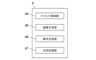
- the image generation device 4 has a tracking control unit 44, an image generation unit 45, a motion generation unit 46, and a generation processing unit 47 as functional blocks.
- the image generator 45 has a function of generating a virtual image in which a virtual tool corresponding to the tool and a virtual work corresponding to the work are arranged in a virtual space.
- the action generator 46 has a function of operating the virtual tool in the virtual image in accordance with the user's operation of the manipulator for operating the virtual tool to perform processing on the virtual work.
- the generation processing unit 47 has a function of generating teaching points for the robot based on the position of the virtual robot in the virtual space.
- the tracking control unit 44 calculates the positions and orientations of the controller 3 and the display 5 in the VR space 80 based on the detection results of the tracking system 6 .
- the tracking control unit 44 executes various arithmetic processing related to tracking based on the irradiation information of the light emitter 61, the detection result of the first sensor 62, and the detection result of the second sensor 63.
- FIG. Specifically, the tracking control unit 44 obtains the position and orientation of the operating device 3 in the real space operating coordinate system based on the detection result of the first sensor 62 and the irradiation information of the light emitting device 61 .
- the tracking control unit 44 obtains the position and orientation of the display 5 in the real space operation coordinate system based on the detection result of the second sensor 63 and the irradiation information of the light emitter 61 .
- the image generation unit 45 generates the VR image 8.
- the image generation unit 45 reads the field definition data 42b and the object definition data 42c from the storage unit 42, and generates the VR space 80 and various objects.
- a VR coordinate system corresponding to the robot coordinate system in the real space is set in the VR space 80 .
- the image generator 45 arranges the virtual robot 81, the first virtual work 84a, the virtual equipment, etc. in the VR space 80 based on the VR coordinate system.
- the image generator 45 converts the relative positional relationship between the virtual robot 81, the first virtual work 84a, and the virtual equipment in the VR coordinate system into the relative positional relationship between the robot 1, the work W, and the equipment in the robot coordinate system. match.
- the image generator 45 generates the virtual robot 81 according to the motion obtained by the motion generator 46 .
- the image generator 45 sets the line of sight in the VR space 80 and generates the VR image 8 according to the line of sight. Specifically, the image generation unit 45 calculates the position and orientation of the display 5 in the VR space 80 based on a predetermined coordinate correspondence relationship from the position and orientation of the display 5 in the operation coordinate system obtained by the tracking control unit 44. Ask for The coordinate correspondence here is the correspondence between the operation coordinate system of the tracking system 6 and the VR coordinate system of the VR space 80 .
- the image generation unit 45 sets the position of the display 5 in the VR coordinate system to the position of the user's line of sight (that is, the position of the eyes) in the VR space 80, and sets the posture of the display 5 in the VR coordinate system to the position of the user in the VR space 80. Set the line of sight.
- the image generator 45 generates the VR image 8 according to the set position and direction of the line of sight.
- the image generator 45 outputs the generated VR image 8 to the display device 5 .
- the motion generation unit 46 generates motions of the virtual robot 81 in the VR space 80 according to the position and orientation of the operation device 3 in the real space obtained by the tracking control unit 44 .
- the action generator 46 obtains the position and orientation of the virtual operator 85 in the VR coordinate system from the position and orientation of the operator 3 in the operation coordinate system, based on the coordinate correspondence relationship between the operation coordinate system and the VR coordinate system.
- the motion generator 46 sets the position of the virtual end effector 83 (specifically, the position of the second virtual injection port 85a) to a position shifted by a specific offset amount in the specific offset direction from the position of the virtual operating device 85 (specifically, the position of the second virtual injection port 85a). position of the first virtual injection port 83a).
- the motion generator 46 matches the posture of the virtual end effector 83 with the posture of the virtual manipulator 85 . Specifically, the motion generator 46 makes the first virtual ejection axis P1 parallel to the second virtual ejection axis P2. Thus, the position and orientation of the virtual end effector 83 are determined.
- the motion generator 46 calculates the position and orientation of the end effector 12 in the real space from the position and orientation of the virtual end effector 83 in the VR space 80 based on the coordinate correspondence relationship between the VR coordinate system and the robot coordinate system. demand.
- the motion generator 46 outputs the position and orientation of the end effector 12 to the taught point generator 2 .
- the teaching point generation device 2 calculates the rotation angle of each joint 14 of the robot arm 11 (that is, the rotation angle of each motor 15) for realizing the position and posture of the end effector 12.
- the taught point generation device 2 outputs the calculated rotation angle of each joint 14 to the motion generation unit 46 .
- the motion generation unit 46 generates the virtual arm 82 so as to realize the rotation angle of each joint 14 input from the teaching point generation device 2 .
- the motion generation unit 46 can generate the virtual robot 81 having the virtual end effector 83 arranged at a position and orientation corresponding to the position and orientation of the operation device 3 in the real space. .
- the motion generating unit 46 generates, or updates, the virtual robot 81 according to the position and orientation of the manipulator 3 in the real space that are obtained at any time, thereby causing the virtual robot 81 to move in conjunction with the manipulator 3 . can be done.
- the motion generator 46 sets motion limits on the motion range of the virtual robot 81 .
- the motion generator 46 notifies that the virtual robot 81 has reached the motion limit.
- the motion generator 46 outputs a warning signal to the image generator 45 when the virtual robot 81 reaches the motion limit.
- the image generator 45 displays that the operation limit has been reached.
- the user is notified that the virtual robot 81 has reached its motion limit.
- the motion restriction includes, for example, motion restriction of the virtual arm 82 itself and motion restriction due to the surrounding environment of the virtual arm 82 .
- the motion limitation of the virtual arm 82 itself is the limitation of the rotation angle of the joint of the virtual arm 82, and is, for example, a singular point.
- the limitation of the rotation angle of the joint of the virtual arm 82 is the same as the limitation of the rotation angle of the joint 14 of the robot arm 11 in the real space.
- Operational restrictions due to the surrounding environment of the virtual arm 82 include restrictions due to interference between the virtual arm 82 and virtual equipment.
- the virtual equipment includes a virtual support device 87, a virtual booth 88, a virtual fence 89 and the like, which will be described later in detail.
- the motion limit of the virtual robot 81 is set after providing a margin for the limit of the rotation angle of the joint 14 and interference with equipment.
- the generation processing unit 47 outputs a generation command to generate a taught point to the taught point generation device 2 based on the operation signal from the operator 3 . Specifically, when the generation processing unit 47 receives the operation signal of the generation switch 32 , the generation processing unit 47 outputs to the taught point generation device 2 a generation command for generating a taught point together with the position and orientation of the operator 3 in the operation coordinate system at that time. . Further, the generation processing unit 47 sets the position and orientation of the virtual end effector 83 when the operation signal of the generation switch 32 is received as a virtual teaching point.
- the generation processing unit 47 sets whether or not to inject paint based on the operation signal from the operation device 3. Specifically, when the generation processing unit 47 receives the operation signal of the injection switch 33, it sets the injection execution of the paint. On the other hand, when the generation processing unit 47 receives the operation signal of the stop switch 34, it sets the injection stop of the paint. When outputting a generation command to the teaching point generation device 2, the generation processing unit 47 also outputs paint injection information (that is, execution of injection or stop of injection).
- the generation processing unit 47 outputs paint injection information to the image generation unit 45 .
- the image generator 45 switches between display and non-display of the virtual paint ejected from the virtual end effector 83 according to the ejection information of the paint.
- the generation processing unit 47 outputs to the taught point generation device 2 an end command for executing end processing for ending the teaching work.
- the teaching point generation device 2 has a rotation angle generation unit 23, a teaching point generation unit 24, a teaching data generation unit 25, and a robot control unit 26 as functional blocks.
- the rotation angle generation unit 23 inputs from the motion generation unit 46 the rotation angles of the joints 14 of the robot arm 11 (that is, the rotation angle). Since the length of each link 13 of the robot arm 11 is known, once the angle of each joint 14 is determined, the position and orientation of the robot 1, that is, the position and orientation of the end effector 12 are uniquely determined. Therefore, when the position and orientation of the end effector 12 are given, the rotation angle generator 23 can obtain the rotation angle of each joint 14 based on the length of each link 13 . The rotation angle generation unit 23 stores the obtained rotation angles of the joints 14 in the storage unit 21 and outputs them to the motion generation unit 46 .
- the teaching point generation unit 24 generates teaching points.
- the teaching point generation unit 24 obtains the position and orientation of the end effector 12 in the robot coordinate system as teaching points based on the position and orientation of the operation device 3 in the operation coordinate system that are input together with the teaching point generation command.
- the virtual end effector 83 is arranged at a position offset with respect to the virtual manipulator 85 in the VR image 8, so the teaching point generation unit 24 sets the position and orientation of the manipulator 3 in the manipulation coordinate system to the robot.
- the position and orientation similarly offset from the position and orientation converted into the coordinate system are used as the position and orientation of the end effector 12 in the robot coordinate system.
- the taught point generation unit 24 stores the generated taught points in the storage unit 21 .
- the teaching point generation unit 24 also saves the paint injection information in the storage unit 21 together with the teaching points.
- the teaching point generation unit 24 stores the teaching point and the paint injection information in the storage unit 21 each time a generation command is input.
- the storage unit 21 accumulates teaching points and paint injection information.
- the teaching data generation unit 25 generates teaching data based on the teaching points generated by the teaching point generation unit 24 . Upon receiving the termination command from the generation processing section 47, the teaching data generating section 25 generates teaching data as one of the termination processes for ending the teaching work.
- the teaching data generation unit 25 reads the generated plurality of teaching points from the storage unit 21 . Further, the teaching data generation unit 25 reads out from the storage unit 21 the rotation angles of the joints 14 of the robot arm 11 and the paint injection information corresponding to each of the teaching points. Thus, the teaching data generation unit 25 generates teaching data.
- the teaching data includes a plurality of sets of rotation angles of a plurality of joints 14, time series information of the plurality of sets, and paint injection information (execution of injection or stop of injection) for each set.
- the robot control unit 26 controls the robot 1 based on the teaching data to operate the robot 1 in real space.
- the robot control unit 26 performs processing after the teaching data is generated, and does not directly contribute to the generation of the teaching data.
- the robot control unit 26 executes automatic operation of the robot 1 .
- a command for automatic operation of the robot 1 is input to the robot control unit 26 by the user operating the teaching point generation device 2 .
- the robot control unit 26 controls the robot 1 based on teaching data.
- the robot control unit 26 calculates the rotation angles of the corresponding motors 15 for realizing the rotation angles of the multiple joints 14 and supplies currents corresponding to the calculated rotation angles to the respective motors 15 .
- the robot control unit 26 also controls the end effector 12 according to the paint injection information included in the teaching data. Specifically, when paint injection is set to be executed, the robot control unit 26 causes the end effector 12 to execute paint injection. On the other hand, when the paint injection is set to stop, the robot control unit 26 stops the paint injection from the end effector 12 .
- the robot 1 moves while drawing a trajectory that passes through the generated teaching points, and sprays paint in a specific section between them. As a result, the work W is painted.
- a teaching operation using the teaching system 100 is performed by a user wearing the display 5 on the head and operating the operation device 3 while viewing the VR image 8 displayed on the display 5 .
- teaching system 100 is configured to be switchable between a first teaching mode and a second teaching mode.
- the first teaching mode is a mode in which the teaching work is performed while displaying the VR image 8 seen by the user existing within the movable range of the virtual robot 81 .
- the second teaching mode is a mode in which the teaching work is performed while displaying the VR image 8 seen by the user who is outside the movable range of the virtual robot 81 . Switching between the first teaching mode and the second teaching mode is performed by the user via the input unit 41, for example.
- the correspondence relationship between the operation coordinate system of the tracking system 6 and the VR coordinate system of the VR space 80 differs between the first teaching mode and the second teaching mode. That is, the correspondence between the operation coordinate system of the tracking system 6 and the VR coordinate system of the VR space 80 includes a first correspondence for the first teaching mode and a second correspondence for the second teaching mode. there is According to the first correspondence, the operating area of the tracking system 6 is associated with the first area 80 a inside the virtual fence 89 . According to the second correspondence, the operating area of the tracking system 6 is associated with the second area 80b outside the virtual fence 89. FIG.
- the user operating in the action area of the tracking system 6 in the real space operates inside the virtual fence 89 which is the first area 80 a in the VR space 80 .
- the user operating in the action area of the tracking system 6 in the real space operates outside the virtual fence 89, which is the second area 80b in the VR space 80.
- FIG. The image generation device 4 switches between the VR image 8 for the first teaching mode and the VR image 8 for the second teaching mode by switching the first correspondence and the second correspondence.
- FIG. 7 is a flow chart of the first teaching mode.
- FIG. 8 is an example of a VR image 8 at the start of painting in the first teaching mode.
- FIG. 9 is an example of a VR image 8 during painting in the first teaching mode.
- the tracking system 6 starts tracking in step S101. That is, the tracking system 6 starts detecting and tracking the positions and orientations of the operation device 3 and the display device 5 in real space.
- the image generation device 4 After the tracking system 6 starts tracking, the image generation device 4 generates the VR image 8 in step S102.
- a display 5 displays the generated VR image 8 .
- the image generation device 4 In the first teaching mode, the image generation device 4 generates the VR image 8 seen by the user present in the first area 80a.
- the VR image 8 in FIG. 3 is the VR image 8 in the first teaching mode.
- the image generation unit 45 reads the field definition data 42b and the object definition data 42c from the storage unit 42, and generates the VR space 80, the virtual robot 81, and the like.
- the second virtual work 84b is arranged in the first area 80a in the vicinity of the first virtual work 84a.
- the motion generation unit 46 generates motions of the virtual robot 81 according to the position and orientation of the operation device 3 .
- the image generation unit 45 and the motion generation unit 46 use the first correspondence for the first teaching mode to convert the positions and orientations of the controller 3 and the display 5 in the operation coordinate system of the tracking system 6 into the VR space. 80 VR coordinate system position and pose.
- the image generation unit 45 causes the virtual robot 81 to perform the motion generated by the motion generation unit 46 , and generates the line-of-sight VR image 8 according to the position and orientation of the display device 5 .
- the user can operate the virtual robot 81 in the VR image 8 by operating the operation device 3 while viewing the VR image 8 displayed on the display device 5 .
- the user attempts to paint the second virtual work 84b in the VR space 80 using the virtual manipulator 85, the user is positioned in the first area 80a.
- the first teaching mode since the user is placed in the first area 80a, the user can perform teaching work while observing the states of the virtual end effector 83 and the first virtual work 84a at a position close to the virtual robot 81.
- the first teaching mode can also be called an approach teaching mode.
- a step S102 generates a virtual image in which a virtual tool corresponding to the tool and a virtual work corresponding to the work are arranged in a virtual space, displays the virtual image, and operates an operating device for operating the virtual tool. This corresponds to operating a virtual tool in a virtual image in response to an operation from a user to execute processing on a virtual work.
- the motion generator 46 determines whether the virtual robot 81 has reached the motion limit in step S103. If the virtual robot 81 reaches the motion limit, a warning is given in step S104. For example, the image generation unit 45 displays a warning in the VR image 8 that the virtual robot 81 has reached its motion limit. Steps S103 and S104 are repeated until the motion of the virtual robot 81 is within the motion limits.
- the motion range of the virtual robot 81 is restricted in the same manner as the actual robot 1.
- the robot 1 in the real space has motion limitations due to the limit of the rotation angle of the joint 14 and interference between the robot arm 11 and a safety fence, a painting booth, or the like. By doing so, it is possible to prevent the virtual robot 81 from performing actions that cannot be realized in the real space.
- step S105 the image generating device 4 determines whether or not an instruction to generate teaching points has been received. Specifically, the generation processing unit 47 determines whether or not an operation signal for the generation switch 32 has been received from the operation device 3 . If the generation processing unit 47 has not received the operation signal of the generation switch 32, the process returns to step S103. In other words, the monitoring of the motion limit and the determination of the teaching point generation instruction are repeated.
- the user operates the generation switch 32 when the virtual robot 81 is positioned at a desired teaching point.
- the generation processing unit 47 receives the operation signal of the generation switch 32
- the taught point generation device 2 generates a taught point in step S106.
- the generation processing unit 47 outputs a generation command to the taught point generation device 2 .
- the teaching point generation device 2 receives the position and orientation of the end effector 12 in the real space corresponding to the position and orientation of the virtual end effector 83 from the image generation device 4 at any time, and calculates the rotation angles of the multiple joints 14. are doing.
- the teaching point generation unit 24 generates the position and orientation of the end effector 12 that are most recent when the generation command is received as a teaching point, and stores the teaching point in the storage unit 21 .
- the teaching point generation unit 24 also stores in the storage unit 21 rotation angles of a plurality of joints 14 corresponding to the positions and postures of the end effector 12 generated as teaching points.
- the generation processing unit 47 sets the position and orientation of the virtual end effector 83 in the VR coordinate system when the operation signal of the generation switch 32 is received as the virtual teaching point.
- the image generation device 4 displays the virtual teaching point 92 on the VR image 8 as shown in FIG. Specifically, the image generator 45 generates the VR image 8 in which the virtual teaching points 92 generated by the generation processor 47 are arranged in the VR space 80 . Further, the image generator 45 displays a trajectory 93 that connects the plurality of virtual teaching points 92 in chronological order. That is, the image generation unit 45 arranges a predetermined number of the most recent virtual teaching points in the VR space 80 among the plurality of virtual teaching points that are sequentially generated over time.
- the generation processing unit 47 determines execution and stop of painting in step S107. Specifically, the generation processing unit 47 determines whether or not there is an operation signal for the ejection switch 33 and an operation signal for the stop switch 34 . The generation processing unit 47 sets execution of painting when receiving the operation signal of the injection switch 33 . On the other hand, when the generation processing unit 47 receives the operation signal of the stop switch 34, it sets the stop of painting. The generation processing unit 47 outputs the painting settings to the taught point generation device 2 and the image generation unit 45 . The taught point generation unit 24 of the taught point generation device 2 associates the painting settings with the taught points and stores them in the storage unit 21 .
- the image generation unit 45 switches between display and non-display of the virtual paint from the virtual end effector 83 and the virtual operation device 85 according to the painting settings. Specifically, when execution of painting is set, the image generator 45 generates the first virtual paint 86a ejected from the virtual end effector 83 and the first virtual paint 86a ejected from the virtual manipulator 85 in step S108. 2 Display the virtual paint 86b. On the other hand, if the stop of painting is set, the image generation unit 45 generates the first virtual paint 86a ejected from the virtual end effector 83 and the second virtual paint ejected from the virtual manipulator 85 in step S109. Hide 86b.
- the user operates the generation switch 32 and the injection switch 33 when the virtual end effector 83 moves to the paint injection start position near the first virtual workpiece 84a. Then, the image generator 45 displays the virtual teaching point 92 and the first virtual paint 86 a and the second virtual paint 86 b in the VR image 8 .
- the first virtual paint 86a corresponds to the paint ejected from the end effector 12.
- the first virtual paint 86a is injected from the first virtual injection port 83a.
- the first virtual paint 86a has a conical outer shape with the first virtual injection axis P1 as the central axis.
- the outer shape of the first virtual paint 86a represents a virtual injection range corresponding to the injection range of the paint in the real space (for example, the range in which the paint can be effectively injected).
- the first virtual paint 86a is an example of a virtual injection target.
- the second virtual paint 86b is injected from the second virtual injection port 85a.
- the second virtual paint 86b has a conical outer shape with the second virtual injection axis P2 as the central axis.
- the outline of the second virtual paint 86b is the same as the outline of the first virtual paint 86a.
- the outer shape of the second virtual paint 86b represents a virtual ejection range corresponding to the ejection range of the paint in the real space.
- the image generation unit 45 displays the first coating 91a on the painted portion of the first virtual work 84a.
- the first coating film 91a is displayed in a color different from that of the surface of the first virtual workpiece 84a.
- the image generator 45 displays the second coating 91b on the painted portion of the second virtual workpiece 84b.
- the second coating 91b is displayed in a color different from that of the surface of the second virtual workpiece 84b.
- the first coating film 91a and the second coating film 91b are examples of indications indicating that they are after treatment, that is, after coating.
- step S110 the image generating device 4 determines whether or not there is an instruction to end the teaching work. Specifically, the image generation device 4 determines whether or not an operation signal for the end switch 35 has been received. If the image generating device 4 has not received the operation signal of the end switch 35, the process returns to step S103. In other words, the processing from the monitoring of the motion limit is repeated, and the generation of teaching points is continued.
- the user As shown in FIG. 9, the user generates teaching points while continuing painting the first virtual work 84a with the virtual end effector 83 and painting the second virtual work 84b with the virtual manipulator 85.
- the image generation unit 45 displays the overlapping portion of the first coating film 91a in a distinguishable manner.
- the overlapping portion 91c where the first coating film 91a overlaps is displayed in a different color from the other portions.
- the overlapping portion 91d where the second coating film 91b overlaps is displayed in a different color from the other portions.
- the user When the teaching point generation is completed, the user operates the end switch 35 .
- the image generation device 4 receives the operation signal of the end switch 35 , the generation processing section 47 outputs a termination command to the teaching point generation device 2 .
- the teaching point generation device 2 generates teaching data in step S111.
- the teaching data generation unit 25 creates teaching data based on a plurality of teaching points and the like stored in the storage unit 21 and stores the created teaching data in the storage unit 21 . This completes the teaching work in the first teaching mode.
- a process of resetting the generated taught points may be executed between the start and the end of generation of the taught points.
- generation of taught points is restarted from the beginning.
- the teaching points stored in the storage unit 21 are reset, and the processing is restarted from step S103.
- the user operates the virtual robot 81 by operating the operation device 3 while viewing the VR image 8 .
- the user's line of sight is placed in the first area 80a, so a VR image 8 approaching the virtual end effector 83 can be generated as shown in FIG. 3 and the like. Therefore, teaching can be performed while confirming the virtual end effector 83 nearby. Since it is the VR image 8 , the user can approach the virtual end effector 83 without worrying about interference between the user and the virtual robot 81 . For example, the user can also generate teaching points while viewing the virtual end effector 83 and the like from a position where the virtual arm 82 interferes.
- the image generation unit 45 switches between display and non-display of various objects and adjusts the display content according to the settings made by the user.
- the image generator 45 includes a virtual arm 82, a second virtual workpiece 84b, a virtual manipulator 85, a first virtual paint 86a, a second virtual paint 86b, a first virtual injection axis P1, a second virtual injection axis.
- a virtual support device 87, a virtual booth 88, a virtual fence 89, a virtual teaching point 92, a trajectory 93, etc. can be individually switched between display and non-display. Switching between display and non-display and display contents can be set by the user via the input unit 41 .
- FIG. 10 is another example of the VR image 8 in the first teaching mode.
- the virtual arm 82 is hidden.
- the image generation device 4 can switch display and non-display of the virtual arm 82 .
- By displaying the virtual arm 82 it is possible to generate teaching points while confirming not only the state of the virtual end effector 83 but also the virtual arm 82.
- FIG. On the other hand, hiding the virtual arm 82 makes it easier to check the status of the virtual end effector 83 . As a result, the portion hidden by the virtual arm 82 can also be confirmed.
- the virtual operator 85 is displayed superimposed on the virtual end effector 83, and the second virtual workpiece 84b, the second virtual paint 86b, and the second virtual injection axis P2 are not displayed.
- the offset amount of the virtual end effector 83 with respect to the virtual manipulator 85 is set to zero.
- the image generator 45 displays the virtual end effector 83 at the position of the virtual controller 85 in the VR space 80 . Note that the image generator 45 may display only the virtual end effector 83 while completely hiding the virtual operation device 85 .
- the VR image 8 becomes an image in which the user grips and moves the virtual end effector 83 .
- the virtual arm 82 is not displayed in the example of FIG. 10, the virtual end effector 83 may be superimposed on the virtual manipulator 85 while the virtual arm 82 is displayed.
- the offset amount of the virtual end effector 83 with respect to the virtual manipulator 85 can be set not only to 0, but also to any value. Also, the offset direction can be set in any direction. The offset direction and offset amount are set by the user through the input unit 41 . The image generator 45 arranges the virtual end effector 83 with the virtual manipulator 85 as a reference based on the set offset direction and offset amount.
- the image generation unit 45 can change, for example, the outer shape (for example, the spread angle, etc.) of the first virtual paint 86a.
- the spread angle of the first virtual paint 86a is narrower and the dimension of the first virtual paint 86a in the direction of the first virtual injection axis P1 is longer than in the examples of FIG. 8 and the like.
- the second virtual paint 86b can be changed in the same manner as the first virtual paint 86a.
- the image generator 45 can change the display mode of the virtual teaching point 92 .
- the image generator 45 is configured to be switchable between a mode in which all virtual teaching points 92 are displayed and a mode in which a finite number of the nearest virtual teaching points 92 are displayed.
- the number of displayed virtual teaching points 92 can be changed.
- the number of displayed virtual teaching points 92 is the most recent two.
- the image generator 45 can also hide the trajectory 93 .
- FIG. 11 is a flow chart of the second teaching mode.
- FIG. 12 is an example of the VR space 80 in the second teaching mode.
- FIG. 13 is an example of a VR image 8 in the second teaching mode.
- the tracking system 6 starts tracking in step S201. That is, the tracking system 6 starts detecting and tracking the positions and orientations of the operation device 3 and the display device 5 in real space.
- the image generation device 4 After the tracking system 6 starts tracking, the image generation device 4 generates the VR image 8 in step S202.
- a display 5 displays the generated VR image 8 .
- the image generating device 4 In the second teaching mode, the image generating device 4 generates the VR image 8 seen by the user present in the second area 80b.
- the image generation unit 45 reads the field definition data 42b and the object definition data 42c from the storage unit 42, and generates the VR space 80, the virtual robot 81, and the like.
- the second virtual workpiece 84b is arranged in the second area 80b.
- the motion generation unit 46 generates motions of the virtual robot 81 according to the position and orientation of the operation device 3 .
- the image generation unit 45 and the motion generation unit 46 use the second correspondence for the second teaching mode to convert the positions and orientations of the controller 3 and the display 5 in the operation coordinate system of the tracking system 6 into the VR space. 80 VR coordinate system position and pose.
- the image generation unit 45 causes the virtual robot 81 to perform the motion generated by the motion generation unit 46 , and generates the line-of-sight VR image 8 according to the position and orientation of the display device 5 .
- the user can operate the virtual robot 81 in the VR image 8 by operating the operation device 3 while viewing the VR image 8 displayed on the display device 5 .
- the user In the second teaching mode, as shown in FIG. 13, the user generates teaching points while painting the second virtual work 84b in the second area 80b with the virtual manipulator 85.
- FIG. Since the user is located in the second area 80b, the user can perform teaching work while observing the overall state of the virtual robot 81 from a position away from the virtual robot 81.
- FIG. The second teaching mode can also be called a remote teaching mode.
- the user In the second teaching mode, the user is away from the virtual end effector 83 and the first virtual work 84a. However, in the second teaching mode as well, the relative positional relationship between the second virtual work 84b and the virtual manipulator 85 is the same as that between the first virtual work 84a and the virtual end effector 83. match the positional relationship. Therefore, the user substantially confirms the relative positional relationship between the first virtual work 84a and the virtual end effector 83 by confirming the relative positional relationship between the second virtual work 84b and the virtual manipulator 85. can do. That is, in the second teaching mode, it is possible to generate teaching points while checking the overall motion of the virtual robot 81 and substantially checking the motion of the virtual end effector 83 .
- a step S202 generates a virtual image in which a virtual tool corresponding to the tool and a virtual work corresponding to the work are arranged in a virtual space, displays the virtual image, and operates an operating device for operating the virtual tool. This corresponds to operating a virtual tool in a virtual image in response to an operation from a user to execute processing on a virtual work.
- the processing after step S203 in the second teaching mode is basically the same as the processing after step S103 in the first teaching mode. However, since the user is away from the virtual end effector 83, the display of the first virtual injection axis P1, the first virtual paint 86a, the first paint film 91a, the overlapping portion 91c, the virtual teaching point 92, and the trajectory 93 is omitted.
- the image generation device 4 of the teaching system 100 has a playback mode that displays the VR image 8 in which the virtual robot 81 operates according to the teaching point. Switching to the playback mode is performed by the user via the input unit 41, for example.
- the playback mode is executed, for example, when checking teaching data. In the playback mode, generation of taught points and generation of taught data are not performed.
- the playback mode is performed, for example, with the display 5 worn on the user's head.
- FIG. 14 is a flow chart of playback mode.
- the tracking system 6 starts tracking in step S301. At this time, the tracking system 6 starts detecting and tracking the position and orientation of the display 5 in real space. Unlike the first teaching mode and the second teaching mode, the tracking system 6 does not detect or track the position and orientation of the manipulator 3 .
- the image generation device 4 acquires teaching data from the storage unit 21 of the teaching point generation device 2 in step S302.
- the image generation device 4 generates the VR image 8 in step S303.
- a display 5 displays the generated VR image 8 .
- the image generation unit 45 reads the field definition data and the object definition data from the storage unit 42, and generates the VR space 80, the virtual robot 81, and the like. In playback mode, the second virtual work 84b and the virtual manipulator 85 are not generated.
- the motion generator 46 causes the virtual robot 81 to move according to the teaching data.
- the image generator 45 basically generates the VR image 8 seen by the user present in the second area 80b. That is, the image generator 45 converts the position and orientation of the display 5 in the operation coordinate system of the tracking system 6 into the position and orientation of the VR coordinate system in the VR space 80 using the second correspondence for the second teaching mode. Convert.
- the image generation unit 45 generates a line-of-sight VR image 8 corresponding to the position and orientation of the display device 5 .
- the playback mode it becomes easier to form a VR image 8 in which the entire virtual robot 81 is within the angle of view.
- the user can confirm the teaching data by confirming the motion of the virtual robot 81 displayed on the display device 5 .
- the display 5 is tracked and the VR image 8 corresponding to the position and orientation of the display 5 is generated, so the user can confirm the motion of the virtual robot 81 from a desired position and desired angle. be able to.
- the playback mode it is possible to hide the virtual equipment and the like in order to make it easier to check the operation of the virtual robot 81 .
- the virtual booth 88 and the virtual fence 89 may be hidden. Display or non-display of various objects can be set by the user via the input unit 41 .
- the user's position in playback mode can be changed.
- the image generation device 4 may generate the VR image 8 from the same user position as in the first teaching mode. That is, the image generator 45 converts the position and orientation of the display 5 in the operation coordinate system of the tracking system 6 into the position and orientation of the VR coordinate system in the VR space 80 using the first correspondence relationship for the first teaching mode. Convert.
- the image generating unit 45 may convert the position and orientation of the display device 5 in the operation coordinate system of the tracking system 6 into the VR of the VR space 80 using the corresponding relationship dedicated to the playback mode, which is different from the first teaching mode and the second teaching mode. It may be converted to the position and orientation of the coordinate system.
- the operating speed of the virtual robot 81 in playback mode may be changeable.
- the operating speed of the virtual robot 81 in the reproduction mode is a normal speed, which is the speed of the robot 1 that actually operates according to the teaching data, a speed faster than the normal speed (i.e., high speed), and a speed slower than the normal speed (i.e., low speed).
- both the virtual end effector 83 and the first virtual work 84a processed by the virtual end effector 83 are displayed in the VR image 8.
- the teaching point can be generated while checking the relative positional relationship between the end effector 83 and the first virtual workpiece 84a.
- teaching points are generated while confirming the motion of the robot 1 in the real space
- the user generates teaching points while confirming the VR image 8 on the display 5. No need to worry about interference. Therefore, the user can easily determine whether the position and movement of the robot 1 are appropriate when generating teaching points.
- the distance from the injection opening 16 to the workpiece W and the orientation of the injection opening 16 with respect to the workpiece W determine the quality of the process. may affect If the surface of the workpiece W is not flat, the influence of the distance from the injection port 16 and the direction of the injection port 16 is particularly large. According to the teaching system 100, the distance from the first virtual exit 83a of the virtual end effector 83 to the workpiece W and the orientation of the first virtual exit 83a can be easily confirmed in the VR image 8. FIG.
- the virtual end effector 83 is processing, ie painting, the first virtual work 84a. This allows the user to generate teaching points while checking the status of processing by the virtual end effector 83 .
- the first coating film 91a is applied to the painted portion of the first virtual workpiece 84a. This allows the user to generate teaching points so that unprocessed portions do not occur. Furthermore, the overlapping portion 91c where the first coating 91a overlaps is displayed so as to be distinguishable from other portions. This allows the user to generate teaching points so as to reduce unevenness in processing.
- the first virtual paint 86a is displayed as an injection target from the virtual end effector 83.
- the user can easily judge whether the relative positional relationship between the virtual end effector 83 and the first virtual work 84a is appropriate. This is particularly effective for processing, such as painting, in which the virtual end effector 83 and the first virtual workpiece 84a are not in contact with each other.
- the second virtual paint 86b is also injected from the virtual manipulator 85 and the second virtual work 84b is painted, the user does not have to look at the virtual end effector 83 and the first virtual work 84a. can also grasp the states of the virtual end effector 83 and the first virtual work 84a.
- the painting of the second virtual work 84b by the virtual manipulator 85 is particularly effective. Even in the first teaching mode, painting of the second virtual work 84b by the virtual manipulator 85 is effective when the second virtual work 84b is separated from the first virtual work 84a.
- VR image 8 virtual facilities corresponding to the facilities existing around the robot 1 are displayed. Specifically, a virtual support device 87 and the like are displayed in the VR image 8 .
- the user can also avoid interference between the robot 1 in the real space and surrounding equipment by generating teaching points so that the virtual robot 81 does not interfere with the virtual equipment.
- the image generation device 4 sets a motion limit for the motion range of the virtual robot 81, and notifies, ie warns, that the virtual robot 81 has reached the motion limit.
- the virtual robot 81 can be freely moved.
- the virtual robot 81 can even perform actions that the robot 1 cannot do in the real space. Therefore, by setting a motion limit in the motion range of the virtual robot 81, it is possible to prevent the virtual robot 81 from performing motions that the robot 1 cannot do in the real space.
- the virtual robot 81 performs actions linked to the actions of the operation device 3 in the real space. That is, the motion of the operation device 3 in real space is tracked by the tracking system 6 .
- the virtual end effector 83 is operated in conjunction with the operation of the manipulator 3 based on the tracking result of the manipulator 3 . Therefore, the user can operate the virtual end effector 83 with the same feeling as moving his/her own hand. As a result, the user can generate teaching points while operating the virtual end effector 83 precisely and as intended. For example, in the case of teaching using a teach pendant, proficiency is required to operate the teach pendant.
- teaching points can be easily generated.
- a virtual controller 85 is also displayed in the VR image 8. Since the virtual operating device 85 corresponding to the operating device 3 operated by the user is displayed in the VR image 8, the sense of the hand and the visual sense match, and the operation of the operating device 3 and the virtual end effector 83 are facilitated. become.
- the virtual manipulator 85 is arranged at a position offset from the virtual robot 81 by a predetermined amount. Specifically, since the virtual end effector 83 is arranged at a position shifted from the virtual manipulator 85 , the user can easily check the state of the virtual end effector 83 .
- a second virtual work 84b corresponding to the virtual manipulator 85 is displayed. It matches the relative positional relationship with the workpiece 84a. Therefore, when the virtual manipulator 85 paints the second virtual work 84b, the virtual end effector 83 paints the same position of the first virtual paint 86a as the second virtual work 84b. That is, when the user paints the second virtual work 84b while looking at the virtual manipulator 85 and the second virtual work 84b in the VR image 8, the virtual end effector 83 paints the first virtual work 84a in the same way. The user can generate teaching points while looking at the virtual manipulator 85 and the second virtual work 84b without looking at the virtual end effector 83.
- the user can also check the state of the virtual end effector 83 by looking at the virtual end effector 83 while painting the second virtual work 84b with the virtual manipulator 85 .
- This allows the user to check the state of the virtual end effector 83 at an angle different from that of the virtual manipulator 85 .
- virtual teaching points 92 corresponding to the generated teaching points are displayed on the VR image 8 .
- This allows the user to generate taught points while checking the generated taught points on the VR image 8 .
- a plurality of virtual teaching points 92 arranged in time series are displayed.
- the user can imagine the trajectory of the virtual end effector 83 from the plurality of virtual teaching points 92 .
- the user can generate teaching points while imagining the trajectory of the virtual end effector 83 .
- the nearest finite number of virtual teaching points 92 are displayed.
- old teaching points that are not very helpful in forming the future trajectory of the virtual end effector 83 are not displayed.
- only a useful number of virtual teaching points 92 are displayed in the VR image 8, and the display of the VR image 8 can be simplified.
- the robot 1 is not limited to an industrial robot, and may be a medical robot.
- the processing performed by the robot 1 is not limited to painting, and may be welding, cleaning, shot blasting, or the like, for example. Further, the processing performed by the robot 1 may be an inspection processing for inspecting the work.
- the object to be ejected by the robot 1 is not limited to paint, but may be ink, cleaning liquid, water, filler material, abrasive (for example, shot material), sealing material, laser, flame, ultrasonic waves, electromagnetism, or the like.
- the inspection process may be a process of inspecting the external appearance of the work using the camera used in the end effector 12 .
- the robot arm 11 may have redundancy.
- the user may select the joint angle of the robot arm 11 corresponding to the generated teaching point from a plurality of joint angles, or the teaching point generation device 2 may select the joint angle based on various conditions. You may choose.
- the image generation device 4 presents a plurality of shapes of the robot arm 11 to the user via the display 5, and the user selects one robot arm 11. A shape may be selected.
- the mechanism for changing the position and orientation of the end effector 12 is not limited to the robot arm 11.
- the robot 1 may have another mechanism for changing the position and posture of the end effector 12 instead of the robot arm 11 .
- the robot arm 11 is not limited to a vertical multi-joint type, and may be a horizontal multi-joint type, a parallel link type, a Cartesian coordinate type, a polar coordinate type, or the like.
- the teaching point generating device 2 may be formed from one device or may be formed from a plurality of devices.
- the teaching point generation device 2 does not have to have the robot control section 26 . That is, the teaching point generation device 2 does not have to have the function of controlling the robot 1 based on the teaching data.
- the teaching point generation device 2 receives the position and orientation of the manipulator 3 in the operation coordinate system corresponding to the virtual teaching point from the image generation device 4, and generates the teaching point of the robot 1 from the received position and orientation of the manipulator 3. but not limited to this.
- the teaching point generating device 2 can employ any method as long as it generates teaching points corresponding to the positions of the virtual robot in the virtual space.
- the teaching point generation device 2 obtains the position and orientation of the end effector 12 in the robot coordinate system from the detection result of the tracking system 6, and further receives a teaching point generation command from the operation device 3 or via the image generation device 4.
- a teaching point may be generated from the position and orientation of the end effector 12 . That is, the taught point generation device 2 may have the function of the tracking control section 44 .
- the teaching point generating device 2 receives the detection result of the first sensor 62 of the tracking system 6 and the irradiation information of the light emitter 61, and based on the detection result of the first sensor 62 and the irradiation information of the light emitter 61, the operation coordinate system The position and orientation of the operation device 3 in .
- the teaching point generation device 2 converts the position and orientation of the manipulator 3 in the operation coordinate system into the position and orientation of the end effector 12 in the robot coordinate system.
- the taught point generating device 2 sets the position and orientation of the end effector 12 when receiving the instruction to generate the taught point as the taught point.
- the teaching point generation device 2 transforms the position and orientation of the virtual teaching point 92 generated by the image generation device 4 in the VR coordinate system into the position and orientation of the teaching point in the robot coordinate system. may be generated.
- the teaching point generating device 2 obtains the position and orientation of the end effector 12 in the robot coordinate system from the detection result of the tracking system 6, and the image generating device 4 obtains the position of the end effector 12 obtained by the teaching point generating device 2.
- the posture may be converted into the position and posture of the virtual end effector 83 in the VR coordinate system to generate the VR image 8, and the virtual teaching point may be generated according to the instruction from the user.
- the taught point generation device 2 receives a taught point generation command via the operation device 3 or the image generation device 4, and uses the position and orientation of the end effector 12 at the time of receiving the taught point generation command as the taught point. good too.
- the teaching point generation device 2 since the operation coordinate system, the robot coordinate system, and the VR coordinate system correspond to each other, the teaching point generation device 2 generates teaching points in the robot coordinate system from the position and orientation of the operator 3 in the operation coordinate system.
- a teaching point in the robot coordinate system may be generated from the position and posture of the virtual teaching point 92 in the VR coordinate system, the virtual end effector 83, or the virtual manipulator 85 or the like. In either case, the generated teaching point of the robot coordinate system corresponds to the position of the virtual robot in the virtual space.
- the robot coordinate system, the operation coordinate system, and the VR coordinate system need only correspond to each other, and their scales do not have to be the same. That is, the image generation device 4 may generate the VR image 8 based on the VR coordinate system with a scale twice that of the robot coordinate system. Also, the robot coordinate system, the operation coordinate system, and the VR coordinate system need only correspond to each other, and may be horizontally or vertically reversed.
- the teaching point generation device 2 and the image generation device 4 are configured as separate hardware devices, but may be configured as a single device.
- the image generation device 4 may be formed from one device, or may be formed from a plurality of devices.
- the virtual images generated by the image generation device 4 are not limited to VR images, and may be AR (Augmented Reality) images or MR (Mixed Reality) images.
- a virtual arm 82, a first virtual work 84a, a second virtual work 84b, a virtual manipulator 85, a first virtual paint 86a, a second virtual paint 86b, a virtual equipment, and a first virtual work 84b are included in the virtual image.
- Some or all of the coating film 91a, the second coating film 91b, the virtual teaching point 92, and the trajectory 93 may not be configured to be switchable between display and non-display.
- the VR image 8 generated by the image generating device 4 should have at least the virtual robot 81, and includes a first virtual work 84a, a second virtual work 84b, a virtual manipulator 85, and a first virtual paint 86a. , the second virtual paint 86b, the virtual equipment, the first coating 91a, the second coating 91b, the virtual teaching point 92, and the locus 93, part or all of which may be omitted.
- the image generation device 4 may have only one or two of the first teaching mode, the second teaching mode, and the reproduction mode. One or two modes may be omitted. For example, among the first teaching mode, the second teaching mode, and the reproduction mode, the image generating device 4 may have only the first teaching mode, or may have only the second teaching mode, It may have only play mode.
- the operating device 3 may be, for example, a teaching pendant.
- the operation unit 31 may be provided in a device separate from the operation device 3 .
- the operation unit 31 may be provided on the display device 5 or the image generation device 4 .
- the controller sensor that detects the position and orientation of the controller 3 in real space is not limited to the tracking system 6.
- the manipulator sensor may be a different tracking system than tracking system 6 .
- the operating device sensor may be a tracking system that includes a light-emitting tracking marker provided on the operating device 3 and a camera that stereo-photographs the real space in which the user exists.
- tracking markers emit infrared light.
- the camera is an infrared camera.
- Image data captured by the camera is transmitted to the image generation device 4 .
- the image generation device 4 obtains the position and orientation of the operation device 3 in real space by image processing the image data from the camera.
- the tracking system may be either an outside-in system or an inside-out system.
- the method of notifying the user that the virtual robot 81 has reached its motion limit is not limited to the notification information included in the VR image 8.
- the notification to the user that the virtual robot 81 has reached the motion limit may be sound or vibration emitted by a device such as the display 5 or the operation device 3 .
- a teaching point is generated each time the generation switch 32 of the operation device 3 is operated, but generation of teaching points is not limited to intermittent generation.
- the teaching points may be generated continuously during a period from the generation start time determined according to the operation of the operation device 3 to the generation end time. In this case, for example, a plurality of points on the movement trajectory of the virtual manipulator 85 moving in the virtual space 80 are generated as teaching points.
- the command for generating teaching data is not limited to the end command.
- the teaching data generation unit 25 receives a command for generating teaching data when a user operates the operation device 3, the display device 5, the input unit 41 of the image generation device 4, or the input unit of the teaching point generation device 2. It may be input to the data generator 25 .
- the teaching data may include a set of multiple joints 14 to complement movement of the end effector 12 between one teaching point and the next teaching point.
- the rotation angle of the joint 14 may be a value related to the rotation angle instead of the rotation angle itself.
- the rotation angle of joint 14 may be the rotation angle of motor 15 .
- the above display of the posture of the virtual end effector 83 and display of the distance from the virtual end effector 83 are merely examples.
- the angle of the first virtual injection axis P1 in the virtual coordinate system or the angle of the first virtual injection axis P1 with respect to the normal direction of the first virtual work 84a is shown in the VR image 8. It may be displayed numerically.
- the first virtual paint 86 a may be color-coded according to the distance from the virtual end effector 83 . That is, the color of first virtual paint 86 a may represent the distance from virtual end effector 83 .
- the distance from the virtual end effector 83 may be displayed numerically in the VR image 8 .
- the display device 5 is not limited to the HMD.
- the display 5 may be a general display.
- the function of operating the robot 1 of the teaching system 100 is not essential. That is, the teaching point generation device 2 does not have to have the robot control section 26 .
- the teaching system 100 may not have a function to generate teaching points, but may generate a virtual image in which the virtual robot operates according to the teaching points, and display the virtual image. That is, this teaching system includes a teaching point generating device that generates teaching points for a robot, an image generating device that generates a virtual image in which a virtual robot corresponding to the robot is arranged in a virtual space, and a virtual image that displays the virtual image. and a display, wherein the image generation device generates the virtual image in which the virtual robot moves according to the teaching point generated by the teaching point generation device. In this case, the teaching point generation device simply generates the input teaching points, and the image generation device generates a virtual image in which the virtual robot operates according to the teaching points generated by the teaching point generation device. According to such a teaching system, it is possible to judge whether or not the teaching point is appropriate while observing the motion of the virtual robot.
- the field definition data 42b, the object definition data 42c, etc. are not limited to those created based on the actual design data of the robot 1, etc. or the actual measurement values of the robot 1, etc.
- the field definition data 42b and the object definition data 42c may be created using simulation software such as offline programming tools or offline teaching software.
- the teacher inputs numerical information through the user interface to create data (for example, field definition data 42b, object definition data 42c, etc.) related to fields and objects in the VR space. be able to.
- the simulation software may allow a computer to realize a function of creating data on fields and objects by scanning a site such as a factory where the robot 1 is actually placed.
- the teaching system 100 may output the generated teaching data to the outside.
- teaching system 100 may output teaching data to a computer loaded with simulation software.
- the computer can display teaching data by the function of simulation software.
- ASICs Application Specific Integrated Circuits
- a circuit or processing circuit that includes a combination of A processor is considered a processing circuit or circuit because it includes transistors and other circuits.
- a circuit, unit, or means is hardware that performs or is programmed to perform the recited functions.
- the hardware may be the hardware disclosed herein, or other known hardware programmed or configured to perform the recited functions.
- a circuit, means or unit is a combination of hardware and software where the hardware is a processor which is considered a type of circuit, the software being used to configure the hardware and/or the processor.
- a teaching system 100 includes a teaching point generation device 2 that generates teaching points for a robot 1 having an end effector 12 (tool) that performs non-contact processing on a workpiece W, and an operator operated by a user. 3, a VR image 8 (virtual tool) in which a virtual end effector 83 (virtual tool) corresponding to the end effector 12 and a first virtual work 84a (virtual work) corresponding to the work W are arranged in a VR space 80 (virtual space). and a display device 5 for displaying a VR image 8.
- the image generation device 4 generates a first virtual A VR image 8 for executing processing on a workpiece 84 a is generated, and the taught point generation device 2 generates a taught point corresponding to the position in the VR space 80 of the virtual end effector 83 generated by the image generation device 4 .
- the user can operate the virtual end effector 83 in the VR space 80 by operating the operation device 3 while viewing the VR image 8 displayed on the display device 5 .
- the user can generate teaching points while operating the virtual end effector 83 in the VR space 80 and executing processing on the first virtual work 84a.
- the user can generate teaching points while checking the relative positional relationship between the virtual end effector 83 and the first virtual workpiece 84a.
- the VR image 8 since the VR image 8 is used, the user can confirm the motion of the virtual robot from various viewpoints such as a viewpoint closer to the virtual robot 81 and a viewpoint away from the virtual robot 81 .
- the user can confirm the motion of the virtual robot 81 from a position close to the virtual robot 81, in other words, within the motion range of the robot 1, which cannot be realized in the real space. Therefore, the user can appropriately generate teaching points.
- the image generation device 4 attaches a display indicating that the processing has been completed to the portion of the first virtual work 84a that has been processed by the virtual end effector 83. . Specifically, the first coating film 91a is applied to the painted portion of the first virtual workpiece 84a.
- the user can distinguish between a processed portion and an unprocessed portion in the first virtual work 84a. Therefore, the user can generate teaching points so that there is no unprocessed portion in the first virtual workpiece 84a.
- the image generation device 4 displays an image indicating the degree of distance from the virtual end effector 83 on the VR image 8 .
- the first virtual ejection axis P ⁇ b>1 extending from the virtual end effector 83 indicates the degree of distance from the virtual end effector 83 .
- the user can generate teaching points while visually grasping the distance from the virtual end effector 83 .
- the user can generate teaching points while appropriately adjusting the distance between the virtual end effector 83 and the first virtual workpiece 84a.
- the image generating device 4 displays an image showing the posture of the virtual end effector 83 on the VR image 8.
- the first virtual ejection axis P1 extending from the virtual end effector 83 indicates the posture of the virtual end effector 83 .
- the user can generate teaching points while visually grasping the posture of the virtual end effector 83 .
- the end effector 12 is configured to inject the paint (predetermined injection target) toward the workpiece W in the process
- the image generation device 4 displays in the VR image 8 the first virtual paint 86a corresponding to the paint or the virtual ejection range corresponding to the ejection range of the paint.
- the user can generate teaching points while visually grasping the paint or the injection range of the paint.
- the processing is painting, welding, cleaning or shot blasting.
- teaching points can be appropriately generated for the robot 1 that performs painting, welding, cleaning, or shot blasting.
- the image generation device 4 indicates that the processed portion of the first virtual work 84a has been processed.
- An image is displayed in the VR image 8 so that the portion where the processing is duplicated can be discriminated.
- an overlapping portion 91c where the first coating film 91a overlaps is attached to the first virtual workpiece 84a.
- the user can visually grasp portions where processing overlaps in the first virtual work 84a. Therefore, the user can generate teaching points so as not to cause unevenness in the processing of the first virtual work 84a.
- the robot 1 further has a robot arm 11 to which the end effector 12 is connected, and the image generating device 4 is a robot arm A virtual arm 82 corresponding to 11 is displayed in the VR image 8 .
- the user can generate teaching points while also confirming the motion of the robot arm 11 .
- the image generation device 4 is configured to switch display and non-display of the virtual arm 82 in the VR image 8 .
- the user can easily check the operation of the virtual end effector 83 by hiding the virtual arm 82, for example.
- the user can confirm the motion of the virtual arm 82 as well as the virtual end effector 83 .
- the robot system 1000 includes the teaching system 100 according to any one of [1] to [9] and the robot 1 that operates according to the teaching points generated by the teaching point generating device 2.
- the user can operate the virtual end effector 83 in the VR space 80 by operating the operation device 3 while viewing the VR image 8 displayed on the display device 5 .
- the user can generate teaching points while operating the virtual end effector 83 in the VR space 80 and executing processing on the first virtual work 84a.
- the user can generate teaching points while checking the relative positional relationship between the virtual end effector 83 and the first virtual workpiece 84a.
- the VR image 8 since the VR image 8 is used, the user can confirm the motion of the virtual robot from various viewpoints such as a viewpoint closer to the virtual robot 81 and a viewpoint away from the virtual robot 81 .
- the user can confirm the motion of the virtual robot 81 from a position close to the virtual robot 81, in other words, within the motion range of the robot 1, which cannot be realized in the real space. Therefore, the user can appropriately generate teaching points.
- a teaching method for the robot 1 is to generate a VR image 8 in which a virtual end effector 83 corresponding to the end effector 12 and a first virtual work 84a corresponding to the work W are arranged in the VR space 80; Displaying the image 8 and operating the virtual end effector 83 in the VR image 8 according to the user's operation to the operation device 3 for operating the virtual end effector 83 to process the first virtual work 84a. and generating a taught point corresponding to the position of the virtual end effector 83 in the VR space 80 .
- the user can operate the virtual end effector 83 in the VR space 80 by operating the operation device 3 while viewing the displayed VR image 8 .
- the user can generate teaching points while operating the virtual end effector 83 in the VR space 80 and executing processing on the first virtual work 84a.
- the user can generate teaching points while checking the relative positional relationship between the virtual end effector 83 and the first virtual workpiece 84a.
- the VR image 8 since the VR image 8 is used, the user can confirm the motion of the virtual robot from various viewpoints such as a viewpoint closer to the virtual robot 81 and a viewpoint away from the virtual robot 81 .
- the user can confirm the motion of the virtual robot 81 from a position close to the virtual robot 81, in other words, within the motion range of the robot 1, which cannot be realized in the real space. Therefore, the user can appropriately generate teaching points.
- the teaching program 42a of the robot 1 has a function of generating a VR image 8 in which a virtual end effector 83 corresponding to the end effector 12 and a first virtual work 84a corresponding to the work W are arranged in the VR space 80, A function of operating the virtual end effector 83 in the VR image 8 according to the user's operation on the operation device 3 for operating the virtual end effector 83, and teaching corresponding to the position of the virtual end effector 83 in the VR space 80 A computer is made to implement a function of generating points.
- the user can operate the virtual end effector 83 in the VR space 80 by operating the operation device 3 while viewing the VR image 8 .
- the user can generate teaching points while operating the virtual end effector 83 in the VR space 80 and executing processing on the first virtual work 84a.
- the user can generate teaching points while checking the relative positional relationship between the virtual end effector 83 and the first virtual workpiece 84a.
- the VR image 8 since the VR image 8 is used, the user can confirm the motion of the virtual robot from various viewpoints such as a viewpoint closer to the virtual robot 81 and a viewpoint away from the virtual robot 81 .
- the user can confirm the motion of the virtual robot 81 from a position close to the virtual robot 81, in other words, within the motion range of the robot 1, which cannot be realized in the real space. Therefore, the user can appropriately generate teaching points.
- robot system 100 teaching system 1 robot 11 robot arm 12 end effector (tool) 14 Joint 2 Teaching point generation device 3 Manipulator 4 Image generation device 42a Teaching program 5 Display device 6 Tracking system (manipulator sensor) 8 VR image (virtual image) 80 VR space (virtual space) 81 virtual robot 82 virtual arm 83 virtual end effector (virtual tool) 84a first virtual work (virtual work) 85 virtual operator 87 virtual support device (virtual equipment) 88 virtual booth (virtual facility) 89 virtual fence (virtual facility)
Landscapes
- Engineering & Computer Science (AREA)
- Robotics (AREA)
- Mechanical Engineering (AREA)
- Physics & Mathematics (AREA)
- General Physics & Mathematics (AREA)
- Automation & Control Theory (AREA)
- Numerical Control (AREA)
- Manipulator (AREA)
Priority Applications (3)
| Application Number | Priority Date | Filing Date | Title |
|---|---|---|---|
| JP2023566350A JP7819211B2 (ja) | 2021-12-07 | 2022-12-07 | 教示システム、ロボットシステム、ロボットの教示方法及びロボットの教示プログラム |
| US18/717,492 US20250026004A1 (en) | 2021-12-07 | 2022-12-07 | Teaching system, robot system, teaching method for robot, and teaching program for robot |
| CN202280081206.4A CN118369191A (zh) | 2021-12-07 | 2022-12-07 | 示教系统、机器人系统、机器人的示教方法以及机器人的示教程序 |
Applications Claiming Priority (2)
| Application Number | Priority Date | Filing Date | Title |
|---|---|---|---|
| JP2021-198841 | 2021-12-07 | ||
| JP2021198841 | 2021-12-07 |
Publications (1)
| Publication Number | Publication Date |
|---|---|
| WO2023106354A1 true WO2023106354A1 (ja) | 2023-06-15 |
Family
ID=86730615
Family Applications (1)
| Application Number | Title | Priority Date | Filing Date |
|---|---|---|---|
| PCT/JP2022/045193 Ceased WO2023106354A1 (ja) | 2021-12-07 | 2022-12-07 | 教示システム、ロボットシステム、ロボットの教示方法及びロボットの教示プログラム |
Country Status (4)
| Country | Link |
|---|---|
| US (1) | US20250026004A1 (https=) |
| JP (1) | JP7819211B2 (https=) |
| CN (1) | CN118369191A (https=) |
| WO (1) | WO2023106354A1 (https=) |
Cited By (3)
| Publication number | Priority date | Publication date | Assignee | Title |
|---|---|---|---|---|
| WO2025053255A1 (ja) * | 2023-09-06 | 2025-03-13 | 川崎重工業株式会社 | 検査システム、検査方法およびロボットシステム |
| JP2025037655A (ja) * | 2023-09-06 | 2025-03-18 | 川崎重工業株式会社 | 検査システムおよび検査方法 |
| JP2025037654A (ja) * | 2023-09-06 | 2025-03-18 | 川崎重工業株式会社 | 検査システムおよび検査方法 |
Citations (5)
| Publication number | Priority date | Publication date | Assignee | Title |
|---|---|---|---|---|
| JP2001216015A (ja) * | 2000-01-31 | 2001-08-10 | Iwate Prefecture | ロボットの動作教示装置 |
| JP2014079824A (ja) * | 2012-10-15 | 2014-05-08 | Toshiba Corp | 作業画面表示方法および作業画面表示装置 |
| JP2015077661A (ja) * | 2013-10-17 | 2015-04-23 | 株式会社安川電機 | ティーチングシステムおよびティーチング方法 |
| WO2019103954A1 (en) * | 2017-11-21 | 2019-05-31 | Intuitive Surgical Operations, Inc. | Systems and methods for master/tool registration and control for intuitive motion |
| JP2021088031A (ja) * | 2019-12-04 | 2021-06-10 | ファナック株式会社 | ロボットプログラミング装置 |
Family Cites Families (5)
| Publication number | Priority date | Publication date | Assignee | Title |
|---|---|---|---|---|
| JP2006051550A (ja) * | 2004-08-10 | 2006-02-23 | Matsushita Electric Ind Co Ltd | 移動体への位置教示装置および位置教示方法 |
| JP2010194687A (ja) * | 2009-02-26 | 2010-09-09 | Yaskawa Electric Corp | 透過型視線検出装置及び移動型ロボットシステム |
| DE102016113060A1 (de) * | 2016-07-15 | 2018-01-18 | Beckhoff Automation Gmbh | Verfahren zum Steuern eines Objekts |
| JP2018036720A (ja) * | 2016-08-29 | 2018-03-08 | 株式会社タカラトミー | 仮想空間観察システム、方法及びプログラム |
| JP7400217B2 (ja) * | 2019-05-30 | 2023-12-19 | セイコーエプソン株式会社 | ロボットシステムおよび可搬型教示装置 |
-
2022
- 2022-12-07 US US18/717,492 patent/US20250026004A1/en active Pending
- 2022-12-07 WO PCT/JP2022/045193 patent/WO2023106354A1/ja not_active Ceased
- 2022-12-07 JP JP2023566350A patent/JP7819211B2/ja active Active
- 2022-12-07 CN CN202280081206.4A patent/CN118369191A/zh active Pending
Patent Citations (5)
| Publication number | Priority date | Publication date | Assignee | Title |
|---|---|---|---|---|
| JP2001216015A (ja) * | 2000-01-31 | 2001-08-10 | Iwate Prefecture | ロボットの動作教示装置 |
| JP2014079824A (ja) * | 2012-10-15 | 2014-05-08 | Toshiba Corp | 作業画面表示方法および作業画面表示装置 |
| JP2015077661A (ja) * | 2013-10-17 | 2015-04-23 | 株式会社安川電機 | ティーチングシステムおよびティーチング方法 |
| WO2019103954A1 (en) * | 2017-11-21 | 2019-05-31 | Intuitive Surgical Operations, Inc. | Systems and methods for master/tool registration and control for intuitive motion |
| JP2021088031A (ja) * | 2019-12-04 | 2021-06-10 | ファナック株式会社 | ロボットプログラミング装置 |
Cited By (5)
| Publication number | Priority date | Publication date | Assignee | Title |
|---|---|---|---|---|
| WO2025053255A1 (ja) * | 2023-09-06 | 2025-03-13 | 川崎重工業株式会社 | 検査システム、検査方法およびロボットシステム |
| JP2025037655A (ja) * | 2023-09-06 | 2025-03-18 | 川崎重工業株式会社 | 検査システムおよび検査方法 |
| JP2025037654A (ja) * | 2023-09-06 | 2025-03-18 | 川崎重工業株式会社 | 検査システムおよび検査方法 |
| JP7654733B2 (ja) | 2023-09-06 | 2025-04-01 | 川崎重工業株式会社 | 検査システムおよび検査方法 |
| JP7707249B2 (ja) | 2023-09-06 | 2025-07-14 | 川崎重工業株式会社 | 検査システムおよび検査方法 |
Also Published As
| Publication number | Publication date |
|---|---|
| US20250026004A1 (en) | 2025-01-23 |
| JP7819211B2 (ja) | 2026-02-24 |
| JPWO2023106354A1 (https=) | 2023-06-15 |
| CN118369191A (zh) | 2024-07-19 |
Similar Documents
| Publication | Publication Date | Title |
|---|---|---|
| WO2023106354A1 (ja) | 教示システム、ロボットシステム、ロボットの教示方法及びロボットの教示プログラム | |
| US10543599B2 (en) | Robot system equipped with video display apparatus that displays image of virtual object in superimposed fashion on real image of robot | |
| US10905508B2 (en) | Remote control robot system | |
| JP6311421B2 (ja) | ティーチングシステム、ロボットシステムおよびティーチング方法 | |
| US7298385B2 (en) | Method and device for visualizing computer-generated informations | |
| US10052765B2 (en) | Robot system having augmented reality-compatible display | |
| Fang et al. | Novel AR-based interface for human-robot interaction and visualization | |
| Zaeh et al. | Interactive laser-projection for programming industrial robots | |
| CN108161904A (zh) | 基于增强现实的机器人在线示教装置、系统、方法、设备 | |
| JP2005106825A (ja) | 受像装置の位置および方向づけの決定方法および装置 | |
| EP2055446A1 (en) | A portable robot control apparatus and a method for controlling a movement of a robot | |
| JP2004209641A (ja) | 工業ロボットをプログラミングするための方法およびシステム | |
| WO2011039542A1 (en) | Method and system of programming a robot | |
| KR20150044812A (ko) | 티칭 시스템 및 티칭 방법 | |
| CN107584206A (zh) | 激光加工机器人系统 | |
| KR20170024769A (ko) | 로봇 제어 장치 | |
| Vagvolgyi et al. | Scene modeling and augmented virtuality interface for telerobotic satellite servicing | |
| JP6469159B2 (ja) | 接触センサによるワーク位置検出プログラム生成機能を備えたオフラインプログラミング装置及び方法 | |
| JP7819210B2 (ja) | 教示システム、ロボットシステム、ロボットの教示方法及びロボットの教示プログラム | |
| CN117207173A (zh) | 机器人的动作路径生成方法及装置、机器人系统以及程序 | |
| Michas et al. | Interactive programming of industrial robots for edge tracing using a virtual reality gaming environment | |
| JP6682120B2 (ja) | ロボットティーチング装置 | |
| Matour et al. | Development of a platform for novel intuitive control of robotic manipulators using augmented reality and cartesian force control | |
| US20230398688A1 (en) | Motion trajectory generation method for robot, motion trajectory generation apparatus for robot, robot system, and program | |
| JP2000039911A (ja) | ロボット制御装置 |
Legal Events
| Date | Code | Title | Description |
|---|---|---|---|
| 121 | Ep: the epo has been informed by wipo that ep was designated in this application |
Ref document number: 22904282 Country of ref document: EP Kind code of ref document: A1 |
|
| WWE | Wipo information: entry into national phase |
Ref document number: 202280081206.4 Country of ref document: CN |
|
| WWE | Wipo information: entry into national phase |
Ref document number: 18717492 Country of ref document: US Ref document number: 2023566350 Country of ref document: JP |
|
| NENP | Non-entry into the national phase |
Ref country code: DE |
|
| 122 | Ep: pct application non-entry in european phase |
Ref document number: 22904282 Country of ref document: EP Kind code of ref document: A1 |