WO2023106213A1 - 情報処理装置 - Google Patents
情報処理装置 Download PDFInfo
- Publication number
- WO2023106213A1 WO2023106213A1 PCT/JP2022/044446 JP2022044446W WO2023106213A1 WO 2023106213 A1 WO2023106213 A1 WO 2023106213A1 JP 2022044446 W JP2022044446 W JP 2022044446W WO 2023106213 A1 WO2023106213 A1 WO 2023106213A1
- Authority
- WO
- WIPO (PCT)
- Prior art keywords
- information
- virtual object
- weather information
- display
- weather
- Prior art date
- Legal status (The legal status is an assumption and is not a legal conclusion. Google has not performed a legal analysis and makes no representation as to the accuracy of the status listed.)
- Ceased
Links
Images




Classifications
-
- G—PHYSICS
- G06—COMPUTING OR CALCULATING; COUNTING
- G06F—ELECTRIC DIGITAL DATA PROCESSING
- G06F3/00—Input arrangements for transferring data to be processed into a form capable of being handled by the computer; Output arrangements for transferring data from processing unit to output unit, e.g. interface arrangements
- G06F3/01—Input arrangements or combined input and output arrangements for interaction between user and computer
-
- G—PHYSICS
- G06—COMPUTING OR CALCULATING; COUNTING
- G06T—IMAGE DATA PROCESSING OR GENERATION, IN GENERAL
- G06T19/00—Manipulating three-dimensional [3D] models or images for computer graphics
-
- H—ELECTRICITY
- H04—ELECTRIC COMMUNICATION TECHNIQUE
- H04L—TRANSMISSION OF DIGITAL INFORMATION, e.g. TELEGRAPHIC COMMUNICATION
- H04L67/00—Network arrangements or protocols for supporting network services or applications
- H04L67/01—Protocols
- H04L67/131—Protocols for games, networked simulations or virtual reality
-
- H—ELECTRICITY
- H04—ELECTRIC COMMUNICATION TECHNIQUE
- H04L—TRANSMISSION OF DIGITAL INFORMATION, e.g. TELEGRAPHIC COMMUNICATION
- H04L67/00—Network arrangements or protocols for supporting network services or applications
- H04L67/50—Network services
- H04L67/52—Network services specially adapted for the location of the user terminal
-
- Y—GENERAL TAGGING OF NEW TECHNOLOGICAL DEVELOPMENTS; GENERAL TAGGING OF CROSS-SECTIONAL TECHNOLOGIES SPANNING OVER SEVERAL SECTIONS OF THE IPC; TECHNICAL SUBJECTS COVERED BY FORMER USPC CROSS-REFERENCE ART COLLECTIONS [XRACs] AND DIGESTS
- Y02—TECHNOLOGIES OR APPLICATIONS FOR MITIGATION OR ADAPTATION AGAINST CLIMATE CHANGE
- Y02A—TECHNOLOGIES FOR ADAPTATION TO CLIMATE CHANGE
- Y02A90/00—Technologies having an indirect contribution to adaptation to climate change
- Y02A90/10—Information and communication technologies [ICT] supporting adaptation to climate change, e.g. for weather forecasting or climate simulation
Definitions
- the present invention relates to an information processing device.
- Patent Literature 1 discloses a display device that superimposes and displays a virtual object on an object (physical object) in a real space visually recognized by a user by using AR technology.
- the display device includes a control condition determination section and a display control section.
- a control condition determination unit determines whether or not a control condition defined for each virtual object is satisfied.
- the display control unit controls display so that the virtual object is displayed in a second display mode different from the first display mode, which is the normal display mode, when it is determined that the control condition is satisfied.
- Virtual objects displayed with XR glasses generally have display data generated in advance. Therefore, depending on the surrounding environment when the virtual object is displayed, the virtual object may not blend in with the surroundings and the user may feel uncomfortable.
- the control conditions and the second display mode are shown, the relationship between the control conditions and the second display mode is not specifically defined. Therefore, the conventional technology described above cannot deal with such a problem.
- the purpose of the present invention is to display virtual objects in a more natural way.
- An information processing apparatus includes a display control unit that causes a display device to display a virtual object associated with a first position in a physical space, and an acquisition that acquires environment information that indicates the environment of the first position. a feature estimation unit for estimating a visual feature at the first position based on the environment information; and image processing for applying the visual feature estimated by the feature estimation unit to the virtual object. and an image processing unit that performs image processing, wherein the display control unit causes the display device to display the virtual object image-processed by the image processing unit.
- FIG. 3 is an explanatory diagram showing the appearance of AR glasses 30.
- FIG. 3 is a block diagram showing the configuration of AR glasses 30.
- FIG. 3 is a block diagram showing the configuration of a terminal device 40;
- FIG. 2 is a block diagram showing the configuration of a virtual object server 20;
- FIG. 3 is a block diagram showing the configuration of a weather information server 50;
- FIG. 5 is an explanatory diagram schematically showing estimation of weather information performed by a weather information management unit 512;
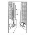
- FIG. 2 is an explanatory diagram schematically showing a physical space R;
- FIG. 4 is a schematic explanatory diagram of display of a virtual object V before image processing;
- FIG. 11 is an explanatory diagram schematically showing a display mode of a virtual object V according to a comparative example
- FIG. 4 is an explanatory diagram schematically showing a display mode of a virtual object V subjected to image processing
- FIG. 11 is an explanatory diagram schematically showing another display mode of the virtual object V subjected to image processing
- 4 is a flowchart showing the operation of the processing device 406; It is a block diagram which shows the whole structure of the information processing system 2 which concerns on 2nd Embodiment. It is a block diagram which shows the structure of the terminal device 40 in 2nd Embodiment.
- First Embodiment A configuration of an information processing system 1 including an information processing apparatus according to a first embodiment of the present invention will be described below.
- FIG. 1 is a diagram showing the overall configuration of an information processing system 1 according to the first embodiment.
- the information processing system 1 includes a wearable device 10 , a virtual object server 20 and a weather information server 50 .
- the weather information server 50 is an example of an environmental information providing server. Also, weather information is an example of environmental information.
- the information processing system 1 is a system that presents various types of information using AR technology to a user wearing AR glasses 30, which will be described later.
- the AR technology is, for example, a technology that allows a user wearing a device such as a transmissive head-mounted display to visually recognize a virtual object V.
- the virtual object V is associated with one point in the physical space.
- first position the position in the physical space associated with the virtual object V
- first position information information indicating the first position
- the virtual object V is displayed on the AR glasses 30 when the user's viewing range includes the first position.
- the AR glasses 30 display the virtual object V so that the user recognizes that the virtual object V is positioned at the first position in the physical space.
- the virtual object V may be displayed and other types of information such as audio information may be output.
- a virtual object V is, for example, a still image, a moving image, a 3DCG model, text, or the like.
- the virtual object V is facility information.
- the virtual object server 20 provides the virtual object V to the AR glasses 30 .
- the AR glasses 30 approaching the first position indicates a state where the first position may enter the user's visual field range or a state where the first position enters the user's visual field range.
- the virtual object V may display the name of the facility and the guidance of the facility using text, for example. Also, the virtual object V may be a moving image or a still image displaying the name of the facility and the guidance of the facility.
- wearable device 10 Although only one wearable device 10 is illustrated in FIG. 1 , the number is only an example, and the information processing system 1 can include any number of wearable devices 10 .
- the wearable device 10 is a device worn by the user to perceive the virtual object V.
- the wearable device 10 includes AR glasses 30 and a terminal device 40 .
- AR glasses 30 are an example of a display device.
- the terminal device 40 is an example of an information processing device.
- the AR glasses 30 and the terminal device 40 are communicably connected to each other.
- the terminal device 40 is, for example, a mobile terminal device such as a smart phone or a tablet.
- the terminal device 40 is connected to the virtual object server 20 via the communication network N so as to be able to communicate with each other.
- the terminal device 40 receives virtual object data DV corresponding to the virtual object V from the virtual object server 20 .
- the terminal device 40 displays the virtual object V on the AR glasses 30 using the virtual object data DV.
- the terminal device 40 is connected to the weather information server 50 via the communication network N so as to be able to communicate with each other.
- the terminal device 40 receives weather information for the first location from the weather information server 50 .
- Weather information is information related to weather conditions, such as presence or absence of rain or snowfall, amount of precipitation, wind direction, wind speed, temperature, humidity, amount of clouds, and presence or absence of thunder.
- the terminal device 40 changes the display mode of the virtual object V on the AR glasses 30 using the weather information.
- AR glass 30 The AR glasses 30 are a transmissive head-mounted display worn on the user's head. Under the control of the terminal device 40, the AR glasses 30 display the virtual object V on the display panels provided in each of the binocular lenses 310A and 310B. As the display device, for example, a goggle-shaped transmissive head-mounted display having functions similar to those of the AR glasses 30 may be used.
- FIG. 2 is an explanatory diagram showing the appearance of the AR glasses 30.
- the AR glasses 30 have temples 301 and 302, a bridge 303, frames 304 and 305, rims 306 and 307, lenses 310A and 310B, and an imaging lens LEN visible from the outside.
- An imaging lens LEN that constitutes the imaging device 324 shown in FIG. 3 is arranged in the bridge 303 .
- a frame 304 is provided with a display panel for the left eye and an optical member for the left eye.
- the display panel is, for example, a liquid crystal panel or an organic EL (Electro Luminescence) panel.
- the display panel for the left eye displays an image based on control from the terminal device 40, which will be described later, for example.
- the optical member for the left eye is an optical member that guides the light emitted from the display panel for the left eye to the lens 310A.
- the frame 304 is provided with a speaker 322 to be described later.
- a display panel for the right eye and an optical member for the right eye are provided on the frame 305 .
- the display panel for the right eye displays an image based on control from the terminal device 40, for example.
- the optical member for the right eye is an optical member that guides the light emitted from the display panel for the right eye to the lens 310B.
- the frame 305 is provided with a speaker 322 which will be described later.
- the rim 306 holds the lens 310A. Rim 307 also holds lens 310B.
- Each of the lenses 310A and 310B has a half mirror.
- the half mirror of the lens 310A guides the light representing the physical space R to the user's left eye by transmitting the light representing the physical space R.
- the half mirror of the lens 310B reflects the light guided by the optical member for the left eye to the left eye of the user.
- the half mirror of the lens 310B guides the light representing the physical space R to the user's right eye by transmitting the light representing the physical space R.
- the half mirror of the lens 310B reflects the light guided by the optical member for the right eye to the right eye of the user.
- the lenses 310A and 310B are positioned in front of the user's left and right eyes.
- a user wearing the AR glasses 30 views the real space R represented by the light transmitted through the lenses 310A and 310B and an image projected by a projection device 321, which will be described later, superimposed on each other.
- FIG. 3 is a block diagram showing the configuration of the AR glasses 30.
- the AR glasses 30 include the temples 301 and 302, the bridge 303, the frames 304 and 305, the rims 306 and 307, the lenses 310A and 310B, and the imaging lens LEN, as well as the projection device 321 and the speaker 322. , a communication device 323 , an imaging device 324 , a GPS device 326 , a storage device 327 , a processing device 328 and a bus 329 .
- Each configuration shown in FIG. 3 is stored in frames 304 and 305, for example.
- the projection device 321, the speaker 322, the communication device 323, the imaging device 324, the storage device 327, and the processing device 328 are interconnected by a bus 329 for communicating information.
- the bus 329 may be configured using a single bus, or may be configured using different buses between elements such as devices.
- the projection device 321 includes a lens 310A, a left-eye display panel, a left-eye optical member, a lens 310B, a right-eye display panel, and a right-eye optical member.
- the projection device 321 functions as a display placed in front of the user's eyeball.
- Light representing the physical space R is transmitted through the projection device 321 .
- the projection device 321 displays an image based on control from the terminal device 40 .
- the image displayed by the projection device 321 is an image displayed as a virtual object V, for example.
- a speaker 322 is located in each of frames 304 and 305 .
- Speaker 322 may be located, for example, in one of frames 304 and 305, at least one of temples 301 and 302, or bridge 303, rather than in each of frames 304 and 305.
- FIG. The speaker 322 is controlled by the terminal device 40 directly or via the processing device 328 of the AR glasses 30 .
- the sound output by the speaker 322 is, for example, the sound that accompanies the virtual object V and the like.
- the speaker 322 may be separate from the AR glasses 30 without being included in the AR glasses 30 .
- the communication device 323 has a communication interface for communicating with other devices.
- the communication device 323 communicates with the terminal device 40 using wireless communication or wired communication.
- the communication device 323 communicates with the communication device 403 (see FIG. 4) of the terminal device 40 using short-range wireless communication such as Bluetooth (registered trademark).
- the imaging device 324 captures an image of a subject and outputs captured image information indicating the captured image (hereinafter referred to as "captured image").
- the imaging range of imaging device 324 may, for example, match or include the user's viewing range. Therefore, the captured image state information includes the real space R of the user's visual field range.
- the captured image generated by the imaging device 324 is transmitted to the terminal device 40 via the communication device 323 as captured image information.
- the imaging device 324 repeats imaging at predetermined imaging intervals, and transmits generated captured image information to the terminal device 40 each time imaging is performed.
- the imaging device 324 has, for example, an imaging optical system and an imaging device.
- the imaging optical system is an optical system including at least one imaging lens LEN (see FIG. 2).
- the imaging optical system may have various optical elements such as a prism, or may have a zoom lens, a focus lens, or the like.
- the imaging device is, for example, a CCD (Charge Coupled Device) image sensor or a CMOS (Complementary MOS) image sensor.
- the GPS device 326 receives radio waves from multiple satellites and generates position information from the received radio waves.
- the position information generated by the GPS device 326 will be referred to as "user position information”
- the position indicated by the user position information will be referred to as "user position”.
- the user position information indicates the position of the user wearing the AR glasses 30 .
- the user location information may be in any format as long as the user location can be specified. In this embodiment, the user location information is latitude and longitude, for example. Note that the user location information may be obtained using means other than the GPS device 326 . For example, information specifying the name of the facility where the AR glasses 30 (user) are located may be received by a beacon or the like provided in the facility.
- the GPS device 326 may be provided in the terminal device 40 . In this case, the position of the terminal device 40 is regarded as the user's position.
- the storage device 327 is a recording medium readable by the processing device 328 .
- Storage 327 includes, for example, non-volatile memory and volatile memory.
- Non-volatile memories are, for example, ROM (Read Only Memory), EPROM (Erasable Programmable Read Only Memory) and EEPROM (Electrically Erasable Programmable Read Only Memory).
- Volatile memory is, for example, RAM (Random Access Memory).
- Storage device 327 stores program PG1.
- a program PG1 is a program for operating the AR glasses 30 .
- the processing device 328 includes one or more CPUs (Central Processing Units).
- CPUs Central Processing Units
- One or more CPUs is an example of one or more processors.
- Each of the processor and CPU is an example of a computer.
- the processing device 328 reads the program PG1 from the storage device 327.
- the processing device 328 functions as an operation control unit 330 by executing the program PG1.
- the operation control unit 330 is composed of circuits such as DSP (Digital Signal Processor), ASIC (Application Specific Integrated Circuit), PLD (Programmable Logic Device), and FPGA (Field Programmable Gate Array). may be
- the operation control unit 330 controls the operation of the AR glasses 30.
- the operation control unit 330 provides the projection device 321 with the image display control signal received by the communication device 323 from the terminal device 40 .
- the projection device 321 displays an image indicated by the image display control signal.
- the operation control unit 330 also provides the speaker 322 with a control signal for audio output that the communication device 323 has received from the terminal device 40 .
- the speaker 322 emits the sound indicated by the control signal for audio output.
- the operation control unit 330 transmits captured image information captured by the imaging device 324 and user position information generated by the GPS device 326 to the terminal device 40 .
- FIG. 4 is a block diagram showing the configuration of the terminal device 40.
- Terminal device 40 includes touch panel 401 , communication device 403 , storage device 405 , processing device 406 and bus 407 .
- the touch panel 401, communication device 403, storage device 405, and processing device 406 are interconnected by a bus 407 for communicating information.
- the bus 407 may be configured using a single bus, or may be configured using different buses between devices.
- the touch panel 401 displays various information to the user and detects the user's touch operation.
- the touch panel 401 serves as both an input device and an output device.
- the touch panel 401 is configured by attaching a touch sensor unit capable of detecting a touch operation between various display panels such as a liquid crystal display panel or an organic EL display panel and a cover glass.
- the touch panel 401 periodically detects the contact position of the user's finger on the touch panel 401 and transmits touch information indicating the detected contact position to the processing device 406 . do.
- the communication device 403 has a communication interface for communicating with other devices.
- the communication device 403 communicates with the AR glasses 30 using wireless communication or wired communication.
- the communication device 403 communicates with the communication device 323 (see FIG. 3) using the same short-range wireless communication as the communication device 323 of the AR glasses 30 .
- the communication device 403 communicates with the virtual object server 20 and the weather information server 50 using wireless communication or wired communication.
- the communication device 403 has an interface that can be connected to the communication network N. Through the communication network N, the communication device 203 (see FIG. 5) of the virtual object server 20 and the communication device 503 (see FIG. 5) of the weather information server 50 (See FIG. 6).
- the storage device 405 is a recording medium readable by the processing device 406 .
- Storage 405 includes, for example, non-volatile memory and volatile memory.
- Non-volatile memories are, for example, ROM, EPROM and EEPROM.
- Volatile memory is, for example, RAM.
- Storage device 405 stores program PG2.
- the program PG2 is a program for operating the terminal device 40 .
- the processing unit 406 includes one or more CPUs.
- One or more CPUs is an example of one or more processors.
- Each of the processor and CPU is an example of a computer.
- the processing device 406 reads the program PG2 from the storage device 405.
- the processing device 406 functions as a virtual object acquisition unit 410, a display control unit 412, an environment information acquisition unit 414, a feature estimation unit 416, and an image processing unit 418 by executing the program PG2.
- At least one of the virtual object acquisition unit 410, the display control unit 412, the environment information acquisition unit 414, the feature estimation unit 416, and the image processing unit 418 may be configured by circuits such as DSP, ASIC, PLD, and FPGA.
- the details of the virtual object acquisition unit 410, the display control unit 412, the environment information acquisition unit 414, the feature estimation unit 416, and the image processing unit 418 will be described later.
- FIG. 5 is a block diagram showing the configuration of the virtual object server 20.
- Virtual object server 20 includes input device 201 , display device 202 , communication device 203 , storage device 205 , processing device 206 and bus 207 .
- the input device 201, the display device 202, the communication device 203, the storage device 205, and the processing device 206 are interconnected by a bus 207 for communicating information.
- the bus 207 may be configured using a single bus, or may be configured using different buses between devices.
- the input device 201 is a device that receives operations performed by the administrator of the virtual object server 20.
- the input device 201 includes a pointing device such as a keyboard, touch pad, touch panel, or mouse.
- the input device 201 may also serve as the display device 202 .
- the display device 202 is a device that displays images and character information.
- the display device 202 displays various images under the control of the processing device 206 .
- various display panels such as a liquid crystal display panel and an organic EL display panel are preferably used as the display device 202 .
- the communication device 203 communicates with the terminal device 40 (see FIGS. 1 and 4) using wireless communication or wired communication.
- the communication device 203 has an interface connectable to the communication network N and communicates with the terminal device 40 via the communication network N.
- the storage device 205 is a recording medium readable by the processing device 206 .
- Storage device 205 includes, for example, non-volatile memory and volatile memory.
- Non-volatile memories are, for example, ROM, EPROM and EEPROM.
- Volatile memory is, for example, RAM.
- Storage device 205 stores program PG3 and virtual object data DV.
- a program PG3 is a program for operating the virtual object server 20 .
- the virtual object data DV includes image data and audio data for displaying the virtual object V, and control data that defines the output mode when the image data and audio data are output.
- the storage device 205 stores one or more virtual object data DV.
- First position information is associated with one or a plurality of pieces of virtual object data DV.
- the virtual object V provided by the virtual object server 20 is pre-associated with the first position information, that is, the display position is pre-determined. do not have. For example, if the virtual object V is a message or image sent to the user by an acquaintance, or an advertisement (for example, an advertisement delivered to a target with a specific attribute regardless of location), the display position is difficult to determine. When displaying these types of virtual objects V, the display position is determined, for example, from within the user's visual field range at the timing when the virtual object V is displayed.
- the processing unit 206 includes one or more CPUs.
- One or more CPUs is an example of one or more processors.
- Each of the processor and CPU is an example of a computer.
- the processing device 206 reads the program PG3 from the storage device 205.
- the processing device 206 functions as an operation control unit 210 by executing the program PG3.
- the operation control unit 210 controls operations of the virtual object server 20 .
- the operation control unit 210 transmits to the terminal device 40 virtual object data DV in which the vicinity of the user position is the first position. More specifically, the motion control unit 210 determines, for example, whether there is a virtual object V whose first position is within a predetermined distance from the user position.
- the motion control unit 210 reads the virtual object data DV of the virtual object V from the storage device 205 and transmits it to the terminal device 40 . At this time, the motion control unit 210 may select and transmit only the virtual object data DV of the virtual object V having the first position in the direction the user is facing.
- FIG. 6 is a block diagram showing the configuration of the weather information server 50.
- Weather information server 50 includes input device 501 , display device 502 , communication device 503 , storage device 505 , processing device 506 and bus 507 .
- Input device 501, display device 502, communication device 503, storage device 505, and processing device 506 are interconnected by bus 507 for communicating information.
- the bus 507 may be configured using a single bus, or may be configured using different buses between devices.
- the input device 501 is a device that accepts operations performed by the administrator of the weather information server 50 .
- the input device 201 includes a pointing device such as a keyboard, touch pad, touch panel, or mouse.
- the input device 501 may also serve as the display device 502 .
- the display device 502 is a device that displays images and character information. Display device 502 displays various images under the control of processing device 506 .
- various display panels such as a liquid crystal display panel and an organic EL display panel are preferably used as the display device 502 .
- the communication device 503 communicates with the terminal device 40 (see FIGS. 1 and 4) using wireless communication or wired communication.
- the communication device 503 has an interface connectable to the communication network N and communicates with the terminal device 40 via the communication network N.
- FIG. Also, the communication device 503 communicates with an observation device 60 (60A to 60C, see FIG. 7), which will be described later, using wireless communication or wired communication.
- the storage device 505 is a recording medium readable by the processing device 506 .
- Storage 505 includes, for example, non-volatile memory and volatile memory.
- Non-volatile memories are, for example, ROM, EPROM and EEPROM.
- Volatile memory is, for example, RAM.
- Storage device 505 stores program PG4 and weather information database DB2.
- program PG4 is a program for operating the weather information server 50 .
- location information is associated with weather information at a location indicated by the location information.
- the processing unit 506 includes one or more CPUs.
- One or more CPUs is an example of one or more processors.
- Each of the processor and CPU is an example of a computer.
- the processing device 506 reads the program PG4 from the storage device 505.
- Processing device 506 functions as operation control unit 510 and weather information management unit 512 by executing program PG4.
- the operation control unit 510 controls the operation of the weather information server 50. For example, when receiving the first location information from the terminal device 40 via the communication device 503 , the operation control unit 510 transmits the first weather information indicating the weather at the display location to the terminal device 40 .
- the first weather information is an example of first environmental information.
- the first weather information may be weather information generated by the weather information management unit 512, which will be described later, or may be weather information stored in the weather information database DB2.
- the weather information management unit 512 manages weather information using the weather information database DB2.
- the weather information management unit 512 acquires second weather information indicating the weather at the second position from the observation device 60 (see FIG. 7) placed at an arbitrary position (hereinafter referred to as “second position”).
- the second position is a position different from the first position.
- the second weather information is an example of second environmental information.
- Observation device 60 is an example of an environmental information measurement device.
- the observation device 60 is installed in a weather observation facility such as a weather station or an unmanned weather observation facility.
- Observation device 60 includes a detection device that detects a physical quantity that indicates the weather at the second location, such as a rain gauge, a thermometer, or an anemometer.
- a physical quantity indicating the weather at the second position is an example of a physical quantity indicating the environment at the second position.
- the second weather information acquired by the weather information management unit 512 is physical quantities detected by the observation device 60 .
- the observation device 60 another AR glass 30 used by another user or an information processing device such as a smartphone may be used.
- the second weather information (for example, the presence or absence of precipitation or wind speed and direction) is estimated from the captured image captured by the imaging device 324, for example.
- the imaging device 324 of the other AR glasses 30 becomes part of the detection device. That is, the detection device may be arranged in another AR glasses 30 that displays the virtual object V superimposed on the real space R within the visual range of another user different from the user of the AR glasses 30 .
- the detection device includes an imaging device 324 that captures an image of the surroundings, and generates weather information by estimating the weather conditions at the location of the detection device based on the captured image captured by the imaging device 324. good.
- the other AR glass 30 is equipped with a thermometer, a hygrometer, an anemometer, etc.
- the thermometer, hygrometer, anemometer, etc. correspond to the detection device.
- the other AR glasses 30 may transmit information measured by a thermometer, a hygrometer, an anemometer, or the like mounted on the device to the weather information server 50 as the second weather information.
- the observation device 60 is connected to the communication network N and transmits the observed (or estimated) second weather information to the weather information server 50 via the communication network N.
- the weather information management unit 512 records the weather information transmitted from the observation device 60 together with the location information of the observation device 60 in the weather information database DB2.
- the weather information management unit 512 uses the second weather information acquired from the observation device 60 to estimate the first weather information.
- the weather information management unit 512 estimates the first weather information based on the second weather information contained in the weather information database DB2, and sends the estimated weather information to the terminal device. Send to device 40 .
- FIG. 7 is an explanatory diagram schematically showing estimation of weather information performed by the weather information management unit 512.
- FIG. 7 the positions of a plurality of observation devices 60A-60C are plotted on a map M.
- FIG. FIG. 7 also shows temperature values observed by the observation devices 60A to 60C. Specifically, a temperature of 22° C. is observed by the observation device 60A, a temperature of 21° C. is observed by the observation device 60B, and a temperature of 18° C. is observed by the observation device 60C.
- the individual temperature values observed by these observation devices 60A to 60C are the second weather information.
- the terminal device 40 requests weather information (first weather information) at a position P (an example of a first position) that is different from any of the observation devices 60A to 60C.
- the weather information management unit 512 divides the temperature difference between the observation devices 60A to 60C by the distance between the observation devices 60A to 60C to calculate the temperature change amount per unit distance on the map M, for example. Assuming that the observation device 60 closest to the position P is the observation device 60C, the temperature at the position P can be calculated from the temperature change per unit distance x the distance between the position P and the observation device 60C + the temperature of the observation device 60C. . Therefore, in the example of FIG. 7, the temperature at position P (first weather information) can be estimated to be 20°C.
- the weather information management unit 512 estimates weather information (first weather information) at the first location using, for example, a conventionally known weather forecast method.
- a plurality of observation devices 60A to 60C are shown in FIG. 7, and the weather information management unit 512 acquires a plurality of second weather information.
- the weather information management section 512 may obtain one piece of second weather information from one observation device 60 (for example, the observation device 60A) and estimate the first weather information based on this.
- the weather information management unit 512 may transmit, for example, weather information observed by the observation device 60 closest to the position P as weather information (first weather information) at the position P (first position).
- first weather information weather information
- the weather information observed by the observation device 60 is 1 weather information.
- processing device 406 functions as the virtual object acquisition unit 410, the display control unit 412, the environment information acquisition unit 414, the feature estimation unit 416, and the image processing unit 418 by executing the program PG2. Function. The details of each functional unit will be described below.
- the virtual object acquisition unit 410 acquires the virtual object V from the virtual object server 20.
- the virtual object acquisition unit 410 transmits user position information to the virtual object server 20 and receives virtual object data DV of a virtual object V having a first position near the user position.
- the display control unit 412 causes the AR glasses 30 to display the virtual object V associated with the first position in the physical space R.
- the display control unit 412 controls the projection device 321 of the AR glasses 30 using the virtual object data DV acquired by the virtual object acquisition unit 410 to display the virtual object V corresponding to the virtual object data DV.
- FIG. 8A is an explanatory diagram schematically showing the physical space R.
- FIG. A building B, a tree T, and the like exist in the physical space R.
- FIG. 8B is a schematic explanatory diagram of the display of the virtual object V before image processing.
- a virtual object V is superimposed on the physical space R and displayed.
- the virtual object V is text information displaying the name of a facility (café ABC) around the user and privilege information at the facility.
- the environment information acquisition unit 414 acquires environment information indicating the environment of the first position.
- the environment information acquisition unit 414 is an example of an acquisition unit.
- the environmental information is weather information about the weather at the first location.
- the environmental information acquisition unit 414 acquires weather information from the weather information server 50 .
- the environment information acquisition unit 414 transmits the first location information to the weather information server 50 and receives weather information at the first location (hereinafter referred to as “first weather information”) from the weather information server 50 .
- the distance between the first position and the user position is often several meters to several tens of meters.
- the first position may be approximated by the user's position.
- the environment information acquisition unit 414 transmits user position information to the weather information server 50 and receives weather information at the user position from the weather information server 50 .
- the weather information at the user's position is treated as the first weather information.
- the feature estimation unit 416 estimates visual features at the first position based on the environmental information.
- environmental information is weather information. Therefore, the visual features estimated by the feature estimation unit 416 are the visual features that occur under the weather indicated by the weather information.
- the visual features based on the weather will be explained in detail below. For example, when it is raining, raindrops make it difficult to see the surroundings in the real space R within the user's field of vision. Also, for example, when fog is applied, the surroundings appear white and misty. Also, when the wind is blowing, light objects such as tree branches and leaves appear to flutter in the direction of the wind. Also, when the sun is shining and the temperature is high, the object appears to sway due to radiant heat from the ground.
- the feature estimation unit 416 estimates changes in how the surroundings are viewed according to the weather conditions as described above.
- the image processing unit 418 performs image processing to give the virtual object V the visual features estimated by the feature estimation unit 416 .
- the display control unit 412 causes the AR glasses 30 to display the virtual object V image-processed by the image processing unit 418 .
- FIG. 9 is an explanatory diagram schematically showing the display mode of the virtual object V according to the comparative example.
- FIG. 10 is an explanatory diagram schematically showing a display mode of a virtual object V subjected to image processing.
- the image processing unit 418 performs image processing such that raindrops D pass through the front surface of the virtual object V as shown in FIG. 10, for example. Therefore, the virtual object V is not emphasized more than necessary, and the virtual object V is displayed in a form that does not make the user feel uncomfortable.
- the feature estimation unit 416 estimates that raindrops pass in front of the virtual object V as a visual feature. Further, the image processing unit 418 gives the virtual object V an effect corresponding to raindrops. Note that when the wind direction and wind strength can be acquired as the first weather information, the feature estimation unit 416 may estimate the falling direction of the raindrops D based on these information.
- FIG. 11 is an explanatory diagram schematically showing another display mode of the image-processed virtual object V.
- the feature estimation unit 416 determines that the visual feature is a feature that the virtual object V deforms based on the wind direction and wind speed. Therefore, the feature estimation unit 416 estimates the degree of deformation of the virtual object V as a visual feature. Further, the image processing unit 418 gives the virtual object V an effect based on the estimated degree of deformation. The image processing unit 418 performs image processing such that the virtual object V flutters in the direction of the wind, as shown in FIG. 11, for example. In FIG.
- the wind is blowing toward the right front of the user in the physical space R, and image processing is also performed on the virtual object V so that it flutters toward the right front of the user. Therefore, the virtual object V blends in with the surrounding environment, and the user recognizes it as if it were a part of the real space R.
- FIG. 12 is a flow chart showing the operation of the processing device 406 .
- the processing device 406 receives user position information from the AR glasses 30 (step S100).
- the processing device 406 functions as the virtual object acquisition unit 410 and transmits user position information to the virtual object server 20 (step S101).
- the virtual object server 20 transmits the virtual object data DV of the virtual object V to the terminal device 40 when there is a virtual object V having the first position near the user position.
- step S102 Until the processing device 406 receives the virtual object data DV (step S102: NO), the processing device 406 returns to step S100 to receive the user position information from the AR glasses 30 and transmit the user position information to the virtual object server 20. to continue.
- the processing device 406 Upon receiving the virtual object data DV (step S102: YES), the processing device 406 functions as the environment information acquisition unit 414 and transmits the first position information of the virtual object data DV received in step S102 to the weather information server 50. (Step S103).
- the weather information server 50 generates first weather information at the first location based on the weather information contained in the weather information database DB2, and transmits the generated first weather information to the terminal device 40.
- the processing device 406 waits until receiving the first weather information (step S104: NO).
- the processing device 406 functions as the feature estimation unit 416 and estimates visual features at the first location based on the first weather information (step S105). .
- the processing device 406 functions as an image processing unit 418, and performs image processing for adding the visual features estimated in step S105 to the virtual object V (step S106).
- the processing device 406 functions as the display control unit 412, superimposes the virtual object V image-processed in step S106 on the physical space R, and displays it on the AR glasses 30 (step S107). After that, the processing device 406 returns the process to step S100 and repeats the subsequent processes.
- the terminal device 40 estimates the visual characteristics at the first position (display position of the virtual object V) based on the environment information, The estimated visual features are given to the virtual object V.
- the environmental information is weather information
- the terminal device 40 estimates visual features that occur under the weather indicated by the weather information. Therefore, the virtual object V is displayed in a more natural manner, especially when the virtual object V is displayed outdoors.
- the weather information server 50 acquires the second weather information from the observation device 60 arranged at the second position different from the first position, and uses the second weather information to obtain the second weather information. 1 Estimate weather information. Therefore, the weather information at the first position is pinpointed, and the error between the weather information and the actual weather is reduced.
- the weather information server 50 collects the weather detected by the other AR glasses 30 and uses it to estimate the first weather information. Therefore, weather information can be obtained at a large number of observation points compared to meteorological observatories or unmanned weather observation facilities, and the estimation accuracy of the first weather information is improved.
- the imaging device 324 is used as the weather information detection device, weather information can be obtained using the standard equipment of the AR glasses 30, improving convenience.
- FIG. 13 is a block diagram showing the overall configuration of the information processing system 2 according to the second embodiment.
- the information processing system 2 comprises a wearable device 10 and a virtual object server 20 . That is, in the second embodiment, the information processing system 2 does not include the weather information server 50 .
- FIG. 14 is a block diagram showing the configuration of the terminal device 40 according to the second embodiment.
- the processing device 406 of the terminal device 40 executes the program PG2 to obtain a virtual object acquisition unit 410, a display control unit 412, an environment information acquisition unit 414, a feature estimation unit 416, an image processing unit 418, and It functions as an environment information estimation unit 420 . That is, in the second embodiment, the processing device 406 also functions as the environment information estimation unit 420 .
- the environment information estimation unit 420 estimates the environment at the first position based on the captured image of the imaging device 324 of the AR glasses 30 .
- the environment information estimation unit 420 generates first weather information based on the image captured by the imaging device 324 . That is, in the second embodiment, the imaging device 324 of the AR glasses 30 functions as one component of the detection device. Also, in the second embodiment, the environment information acquisition unit 414 acquires the first weather information generated by the environment information estimation unit 420 .
- the captured image captured by the imaging device 324 of the AR glasses 30 is an image captured around the AR glasses 30, and shows the state of the surroundings of the AR glasses 30 including the first position.
- the environment information estimation unit 420 estimates physical quantities indicating the weather around the AR glasses 30 using image analysis. As a specific example, the environment information estimation unit 420 calculates the physical quantity (amount of clouds, presence/absence of precipitation, amount of precipitation or sunshine) indicating the weather at the first position based on the state of the sky in the captured image captured by the imaging device 324, for example. strength, etc.). Also, the environment information estimation unit 420 estimates the wind direction at the first position, for example, based on the shaking of an object (such as branches and leaves of a tree) captured in the captured image. In this case, the environment information estimation unit 420 may estimate the strength of the wind (wind speed) based on the magnitude of the shaking of the object.
- the weather information acquisition unit 414 Weather information detected by the detection device may be obtained.
- the first weather information is estimated based on the captured image captured by the imaging device 324 of the AR glasses 30 . Therefore, the terminal device 40 can acquire the first weather information without connecting to the weather information server 50, which simplifies the system. Further, according to the second embodiment, it is possible to pinpoint and reliably acquire the weather information at the first position. Therefore, the accuracy of the estimation performed by the feature estimation unit 416 is improved, and the virtual object V is displayed in a more natural form.
- the weather at the first position may be estimated based on the captured image. For example, when the first weather information obtained from the weather information server 50 indicates that cloudy weather is expected to change to rain, it may be determined from the captured image whether it is actually starting to rain at the first location. Further, for example, although precipitation is shown in the captured image, it may be difficult to determine whether the precipitation is rain or snow only with the captured image. In this case, the temperature at the first location may be obtained from the weather information server 50, and whether the precipitation is rain or snow may be determined based on the temperature.
- the AR glasses 30 and the terminal device 40 are separate bodies. Not limited to this, the AR glasses 30 may have the function of the terminal device 40, for example. That is, the communication device 323 of the AR glasses 30 can be connected to the communication network N so that the AR glasses 30 can receive virtual object data directly from the virtual object server 20 and weather information directly from the weather information server 50. can be
- the terminal device 40 is not required, which is advantageous in simplifying the system configuration.
- the display device is the AR glasses 30 .
- the display device is not limited to this, and any device that can display the virtual object V associated with the position information may be used.
- the display device may be VR glasses, MR glasses, or the display of a smart phone when executing the AR function.
- the environmental information is not limited to weather information, and may be, for example, the progress of autumn leaves, the flowering of cherry blossoms, the state of sunshine, and the like.
- the image processing unit 418 may change the tone of the display color of the virtual object V according to the color of the surrounding leaves. Further, when the environmental information is the state of blossoming cherry blossoms, the image processing unit 418 may perform image processing to superimpose the image of the cherry blossom petals on the virtual object V when the cherry blossom petals are scattered.
- the image processing unit 418 reduces at least one of the brightness and saturation of the virtual object V when the surroundings become dark, and reduces the brightness or saturation of the virtual object V when the surroundings become bright. At least one of saturation may be increased.
- the virtual object V is displayed in a display mode that blends in with the surrounding environment. Therefore, the virtual object V is displayed without making the user feel uncomfortable.
- Each function illustrated in FIGS. 3 to 6 is realized by any combination of hardware and software.
- a method for realizing each function is not particularly limited.
- Each function may be implemented using one device physically or logically coupled, or two or more devices physically or logically separated, directly or indirectly (e.g., wired, It may also be implemented using devices that are configured by connecting (eg, wirelessly).
- Each function may be implemented by combining software in the one device or the plurality of devices.
- apparatus may be read as other terms such as circuits, devices or units.
- storage device 205 storage device 327, storage device 405 and storage device 505
- CD-ROM Compact Disc ROM
- other optical discs hard disk drives, flexible discs, magneto-optical discs (e.g. compact discs, digital versatile discs, Blu-ray (registered trademark) discs), smart cards, flash memory ( card, stick, key drive), floppy disk, magnetic strip, and/or the like.
- the program may be transmitted from a network via an electric communication line.
- Each of the first embodiment, second embodiment, first to third modifications is LTE (Long Term Evolution), LTE-A (LTA-Advanced), SUPER 3G, IMT-Advanced, 4G (4th generation mobile communication system), 5G (5th generation mobile communication system), 6th generation mobile communication system (6G), xth generation mobile communication system nication system (xG) (x is, for example, an integer or a decimal number), FRA (Future Radio Access) , NR (new Radio), New radio access (NX), Future generation radio access (FX), W-CDMA (registered trademark), GSM (registered trademark), CDMA2000, UMB (Ultra Mobile Broadband), IEEE 802.11 ( Wi-Fi (registered trademark)), IEEE 802.16 (WiMAX (registered trademark)), IEEE 802.20, UWB (Ultra-WideBand), Bluetooth (registered trademark), other suitable systems and systems utilizing these may be applied to at least one of the next generation systems that are extended, modified, created, defined
- input/output information may be stored in a specific location (for example, memory), or managed. It may be managed using a table. Input/output information and the like may be overwritten, updated, or appended. The output information and the like may be deleted. The entered information and the like may be transmitted to another device.
- a specific location for example, memory
- Input/output information and the like may be overwritten, updated, or appended.
- the output information and the like may be deleted.
- the entered information and the like may be transmitted to another device.
- the determination may be made based on the value (0 or 1) represented by one bit. However, it may be performed based on a true/false value (Boolean: true or false), or may be performed based on numerical comparison (for example, comparison with a predetermined value).
- the programs exemplified in each of the first embodiment, second embodiment, and first to third modifications are referred to as software, firmware, middleware, microcode, hardware description language, or other names.
- instruction, instruction set, code, code segment, program code, subprogram, software module, application, software application, software package, routine, subroutine, object, executable file, thread of execution, procedure or function, whether called by should be interpreted broadly to mean Software, instructions, etc. may also be transmitted and received over a transmission medium.
- the software uses wired technology (coaxial cable, fiber optic cable, twisted pair and digital subscriber line (DSL), etc.) and/or wireless technology (infrared, microwave, etc.) to access websites, servers, or other When transmitted from a remote source, these wired and/or wireless technologies are included within the definition of transmission media.
- wired technology coaxial cable, fiber optic cable, twisted pair and digital subscriber line (DSL), etc.
- wireless technology infrared, microwave, etc.
- the terminal device 40 may be a mobile station.
- a mobile station is defined by those skilled in the art as subscriber station, mobile unit, subscriber unit, wireless unit, remote unit, mobile device, wireless device, wireless communication device, remote device, mobile subscriber station, access terminal, mobile terminal, wireless It may also be referred to as a terminal, remote terminal, handset, user agent, mobile client, client or some other suitable terminology.
- a mobile station may be called a transmitting device, a receiving device, a communication device, or the like.
- a mobile station may be a device mounted on a mobile, or the mobile itself, or the like.
- a moving object means an object that can move. The moving speed of the moving body is arbitrary. The moving object can be stopped.
- Mobile bodies include, for example, vehicles, transport vehicles, automobiles, motorcycles, bicycles, connected cars, excavators, bulldozers, wheel loaders, dump trucks, forklifts, trains, buses, carts, rickshaws, ships (ship and other watercraft), Including, but not limited to, airplanes, rockets, satellites, drones, multicopters, quadcopters, balloons, and anything mounted thereon.
- the mobile body may be a mobile body that autonomously travels based on an operation command.
- the mobile object may be a vehicle (e.g., car, airplane, etc.), an unmanned mobile object (e.g., drone, self-driving car, etc.), or a robot (manned or unmanned).
- vehicle e.g., car, airplane, etc.
- unmanned mobile object e.g., drone, self-driving car, etc.
- a robot manned or unmanned.
- Mobile stations also include devices that are not necessarily mobile during communication operations.
- the mobile station may be an IoT (Internet of Things) device such as a sensor.
- determining encompasses a wide variety of actions.
- Determination includes, for example, judging, calculating, computing, processing, deriving, investigating, looking up, searching, inquiry (e.g., table , searching in a database or other data structure), ascertaining what has been “determined”, and the like.
- determining includes receiving (e.g., receiving information), transmitting (e.g., transmitting information), input, output, accessing ( For example, access to data in memory) may be considered to be a "judgment” or “decision”.
- determining may include considering resolving, selecting, choosing, establishing, comparing, etc. to be “determined.” Thus, “determining” may include deeming some action "determined”. Also, “determination” may be read as “assuming", “expecting", “considering”, or the like.
- connection refers to two or more elements means any direct or indirect connection or coupling between, and may include the presence of one or more intermediate elements between two elements that are “connected” or “coupled” to each other. Couplings or connections between elements may be physical, logical, or a combination thereof. For example, “connection” may be read as "access”.
- two elements are defined using at least one of one or more wires, cables, and printed electrical connections and, as some non-limiting and non-exhaustive examples, in the radio frequency domain. , electromagnetic energy having wavelengths in the microwave and light (both visible and invisible) regions, and the like.
Landscapes
- Engineering & Computer Science (AREA)
- General Engineering & Computer Science (AREA)
- Theoretical Computer Science (AREA)
- Computer Networks & Wireless Communication (AREA)
- Signal Processing (AREA)
- Physics & Mathematics (AREA)
- General Physics & Mathematics (AREA)
- Computer Graphics (AREA)
- Computer Hardware Design (AREA)
- Software Systems (AREA)
- Human Computer Interaction (AREA)
- User Interface Of Digital Computer (AREA)
Priority Applications (1)
| Application Number | Priority Date | Filing Date | Title |
|---|---|---|---|
| JP2023566279A JP7717839B2 (ja) | 2021-12-10 | 2022-12-01 | 情報処理装置 |
Applications Claiming Priority (2)
| Application Number | Priority Date | Filing Date | Title |
|---|---|---|---|
| JP2021-200674 | 2021-12-10 | ||
| JP2021200674 | 2021-12-10 |
Publications (1)
| Publication Number | Publication Date |
|---|---|
| WO2023106213A1 true WO2023106213A1 (ja) | 2023-06-15 |
Family
ID=86730351
Family Applications (1)
| Application Number | Title | Priority Date | Filing Date |
|---|---|---|---|
| PCT/JP2022/044446 Ceased WO2023106213A1 (ja) | 2021-12-10 | 2022-12-01 | 情報処理装置 |
Country Status (2)
| Country | Link |
|---|---|
| JP (1) | JP7717839B2 (https=) |
| WO (1) | WO2023106213A1 (https=) |
Cited By (1)
| Publication number | Priority date | Publication date | Assignee | Title |
|---|---|---|---|---|
| JP7723854B1 (ja) * | 2024-08-07 | 2025-08-14 | Kddi株式会社 | 情報処理装置、情報処理方法及びプログラム |
Citations (3)
| Publication number | Priority date | Publication date | Assignee | Title |
|---|---|---|---|---|
| JP2008083289A (ja) * | 2006-09-27 | 2008-04-10 | Sony Corp | 撮像表示装置、撮像表示方法 |
| JP2014142847A (ja) * | 2013-01-25 | 2014-08-07 | Masanori Ihara | 拡張現実における情報提供サービス方法 |
| WO2021241431A1 (ja) * | 2020-05-29 | 2021-12-02 | ソニーグループ株式会社 | 情報処理装置、情報処理方法、及びコンピュータが読み取り可能な記録媒体 |
Family Cites Families (1)
| Publication number | Priority date | Publication date | Assignee | Title |
|---|---|---|---|---|
| JPH06331756A (ja) * | 1993-05-24 | 1994-12-02 | Hitachi Plant Eng & Constr Co Ltd | 予測システム |
-
2022
- 2022-12-01 JP JP2023566279A patent/JP7717839B2/ja active Active
- 2022-12-01 WO PCT/JP2022/044446 patent/WO2023106213A1/ja not_active Ceased
Patent Citations (3)
| Publication number | Priority date | Publication date | Assignee | Title |
|---|---|---|---|---|
| JP2008083289A (ja) * | 2006-09-27 | 2008-04-10 | Sony Corp | 撮像表示装置、撮像表示方法 |
| JP2014142847A (ja) * | 2013-01-25 | 2014-08-07 | Masanori Ihara | 拡張現実における情報提供サービス方法 |
| WO2021241431A1 (ja) * | 2020-05-29 | 2021-12-02 | ソニーグループ株式会社 | 情報処理装置、情報処理方法、及びコンピュータが読み取り可能な記録媒体 |
Cited By (1)
| Publication number | Priority date | Publication date | Assignee | Title |
|---|---|---|---|---|
| JP7723854B1 (ja) * | 2024-08-07 | 2025-08-14 | Kddi株式会社 | 情報処理装置、情報処理方法及びプログラム |
Also Published As
| Publication number | Publication date |
|---|---|
| JPWO2023106213A1 (https=) | 2023-06-15 |
| JP7717839B2 (ja) | 2025-08-04 |
Similar Documents
| Publication | Publication Date | Title |
|---|---|---|
| CN105139347B (zh) | 一种结合暗通道先验原理的偏振成像去雾方法 | |
| US9696798B2 (en) | Eye gaze direction indicator | |
| US20150146004A1 (en) | Centralized video surveillance data in head mounted device | |
| US20150317838A1 (en) | Registration for vehicular augmented reality using auto-harmonization | |
| CN106104667B (zh) | 具有光透射率的选择可控制区域的挡风玻璃及其控制方法 | |
| US20180111451A1 (en) | Automated windshield glare elimination assistant | |
| KR20220056834A (ko) | 표시 방법, 장치, 단말 기기, 컴퓨터 판독 가능한 저장 매체 및 컴퓨터 프로그램 | |
| CN104634784A (zh) | 大气能见度监测方法和装置 | |
| JP7717839B2 (ja) | 情報処理装置 | |
| US12209878B2 (en) | Navigation method, electronic device and readable storage medium | |
| US11294456B2 (en) | Perspective or gaze based visual identification and location system | |
| CN109842790A (zh) | 影像信息显示方法与显示器 | |
| US10600325B1 (en) | Avionic display system | |
| CN105070204A (zh) | 一种微型amoled光学显示器 | |
| CN114998771B (zh) | 飞行器视景增强的显示方法、系统、飞行器及存储介质 | |
| Toet et al. | The TRICLOBS dynamic multi-band image data set for the development and evaluation of image fusion methods | |
| US11836978B2 (en) | Related information output device | |
| US11827150B2 (en) | Computer-implemented object visibility improvement by interposing an image in a viewer's line-of-sight | |
| TW201333753A (zh) | 具有實景導覽功能之透明顯示器 | |
| KR20210088487A (ko) | 3d 헤드업디스플레이 시스템 및 그의 제어 방법 | |
| CN103727951B (zh) | 无屏导航系统 | |
| JP7723754B2 (ja) | 情報処理装置 | |
| WO2020230892A1 (ja) | 処理装置 | |
| CN109443377A (zh) | 一种图像处理方法、系统、服务器和存储介质 | |
| US20250155971A1 (en) | Display control apparatus |
Legal Events
| Date | Code | Title | Description |
|---|---|---|---|
| 121 | Ep: the epo has been informed by wipo that ep was designated in this application |
Ref document number: 22904144 Country of ref document: EP Kind code of ref document: A1 |
|
| WWE | Wipo information: entry into national phase |
Ref document number: 2023566279 Country of ref document: JP |
|
| NENP | Non-entry into the national phase |
Ref country code: DE |
|
| 122 | Ep: pct application non-entry in european phase |
Ref document number: 22904144 Country of ref document: EP Kind code of ref document: A1 |