WO2023106158A1 - 自動運転を行う農業機械のための経路計画システム - Google Patents
自動運転を行う農業機械のための経路計画システム Download PDFInfo
- Publication number
- WO2023106158A1 WO2023106158A1 PCT/JP2022/043810 JP2022043810W WO2023106158A1 WO 2023106158 A1 WO2023106158 A1 WO 2023106158A1 JP 2022043810 W JP2022043810 W JP 2022043810W WO 2023106158 A1 WO2023106158 A1 WO 2023106158A1
- Authority
- WO
- WIPO (PCT)
- Prior art keywords
- work
- agricultural
- agricultural machine
- route
- farm
- Prior art date
- Legal status (The legal status is an assumption and is not a legal conclusion. Google has not performed a legal analysis and makes no representation as to the accuracy of the status listed.)
- Ceased
Links
Images










Classifications
-
- G—PHYSICS
- G01—MEASURING; TESTING
- G01C—MEASURING DISTANCES, LEVELS OR BEARINGS; SURVEYING; NAVIGATION; GYROSCOPIC INSTRUMENTS; PHOTOGRAMMETRY OR VIDEOGRAMMETRY
- G01C21/00—Navigation; Navigational instruments not provided for in groups G01C1/00 - G01C19/00
- G01C21/26—Navigation; Navigational instruments not provided for in groups G01C1/00 - G01C19/00 specially adapted for navigation in a road network
- G01C21/34—Route searching; Route guidance
-
- G—PHYSICS
- G01—MEASURING; TESTING
- G01C—MEASURING DISTANCES, LEVELS OR BEARINGS; SURVEYING; NAVIGATION; GYROSCOPIC INSTRUMENTS; PHOTOGRAMMETRY OR VIDEOGRAMMETRY
- G01C21/00—Navigation; Navigational instruments not provided for in groups G01C1/00 - G01C19/00
- G01C21/26—Navigation; Navigational instruments not provided for in groups G01C1/00 - G01C19/00 specially adapted for navigation in a road network
- G01C21/34—Route searching; Route guidance
- G01C21/36—Input/output arrangements for on-board computers
- G01C21/3667—Display of a road map
-
- A—HUMAN NECESSITIES
- A01—AGRICULTURE; FORESTRY; ANIMAL HUSBANDRY; HUNTING; TRAPPING; FISHING
- A01B—SOIL WORKING IN AGRICULTURE OR FORESTRY; PARTS, DETAILS, OR ACCESSORIES OF AGRICULTURAL MACHINES OR IMPLEMENTS, IN GENERAL
- A01B69/00—Steering of agricultural machines or implements; Guiding agricultural machines or implements on a desired track
- A01B69/007—Steering or guiding of agricultural vehicles, e.g. steering of the tractor to keep the plough in the furrow
- A01B69/008—Steering or guiding of agricultural vehicles, e.g. steering of the tractor to keep the plough in the furrow automatic
-
- G—PHYSICS
- G06—COMPUTING OR CALCULATING; COUNTING
- G06Q—INFORMATION AND COMMUNICATION TECHNOLOGY [ICT] SPECIALLY ADAPTED FOR ADMINISTRATIVE, COMMERCIAL, FINANCIAL, MANAGERIAL OR SUPERVISORY PURPOSES; SYSTEMS OR METHODS SPECIALLY ADAPTED FOR ADMINISTRATIVE, COMMERCIAL, FINANCIAL, MANAGERIAL OR SUPERVISORY PURPOSES, NOT OTHERWISE PROVIDED FOR
- G06Q50/00—Information and communication technology [ICT] specially adapted for implementation of business processes of specific business sectors, e.g. utilities or tourism
- G06Q50/02—Agriculture; Fishing; Forestry; Mining
Definitions
- the present disclosure relates to a route planning system for agricultural machinery that operates automatically.
- Patent Documents 1 and 2 disclose an example of a system that automatically drives an unmanned working vehicle between two fields separated from each other by a road.
- This disclosure provides techniques for more efficient route planning for agricultural machinery that operates automatically.
- a route planning system is a route planning system for agricultural machines that operate automatically.
- the route planning system includes a storage device that stores a map including a plurality of farm fields, a plurality of waiting locations, and roads connecting the plurality of farm fields and the plurality of waiting locations, and each operation of the agricultural machine on the map. and a processing unit for generating a route for the day.
- the processing device based on information indicating at least one of the growth status of crops in the plurality of fields, the progress status of farm work in the plurality of fields, the planting status in the plurality of fields, and weather conditions, is performed on each work day. determines a specific waiting place from among the plurality of waiting places to which the agricultural machine moves after performing the last agricultural work, and generates a route from the field where the last agricultural work is performed to the specific waiting place. do.
- a route planning system is a route planning system for agricultural machines that automatically operate across multiple regions.
- the route planning system includes a storage device that stores a map of an area including the plurality of regions, and a processing device.
- the processing device determines a timing for the agricultural work to be performed by the agricultural machine in each of the plurality of areas based on information indicating a rough estimate of the timing of the agricultural work to be performed by the agricultural machine for each area.
- a route of the agricultural machine on the map is generated so that the agricultural machine performs the agricultural work at the determined time.
- a computer-readable storage medium may include both volatile and non-volatile storage media.
- a device may consist of a plurality of devices. When the device is composed of two or more devices, the two or more devices may be arranged in one device, or may be divided and arranged in two or more separate devices. .
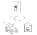
- FIG. 1 is a diagram for explaining an overview of an agricultural management system according to the exemplary first embodiment of the present disclosure
- FIG. FIG. 2 is a side view schematically showing an example of a work vehicle and implements connected to the work vehicle
- 1 is a block diagram showing a configuration example of a work vehicle and implements
- FIG. 1 is a conceptual diagram showing an example of a work vehicle that performs positioning by RTK-GNSS
- FIG. 3 is a diagram showing an example of an operation terminal and an operation switch group provided inside a cabin; It is a block diagram which illustrates the hardware constitutions of a management apparatus and a terminal device.
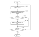
- FIG. 4 is a diagram schematically showing an example of a working vehicle that automatically travels along a target route in a field; 4 is a flowchart showing an example of steering control operation during automatic driving; FIG. 3 is a diagram showing an example of a working vehicle that travels along a target route P; FIG. 4 is a diagram showing an example of a work vehicle that is shifted to the right from a target path P; FIG. 4 is a diagram showing an example of a work vehicle that is shifted to the left from a target path P; FIG. 4 is a diagram showing an example of a work vehicle facing in a direction that is inclined with respect to a target path P; FIG.
- FIG. 4 is a diagram schematically showing an example of a situation in which a plurality of work vehicles are automatically traveling on roads inside and outside a field; It is a figure which shows an example of the setting screen displayed on a terminal device. It is a figure which shows the example of the schedule of agricultural work produced by the management apparatus.
- FIG. 4 is a diagram showing an example of a map referred to when planning a route;
- FIG. 4 is a diagram showing an example of a global route;
- FIG. 10 is a diagram showing another example of global paths;
- FIG. 4 is a diagram showing an example of global and local paths generated in an environment with obstacles;
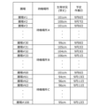
- FIG. 10 is a diagram showing another example of a map of an area including multiple waiting areas; It is a figure which shows an example of the table which shows the correspondence of a waiting place and an agricultural field. It is a figure which shows an example of the map which specified the correspondence of a waiting place and an agricultural field. It is a figure which shows an example of the table which manages the growth condition of the crops in each field.
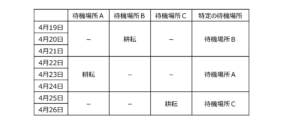
- FIG. 21 is a table showing an example of the distribution of working days in a plurality of fields corresponding to the example shown in FIG. 20; FIG. It is a figure which shows an example of the table which manages the progress of the agricultural work in each field.
- FIG. 23 is a diagram showing an example of distribution of working days in a plurality of fields corresponding to the example shown in FIG.
- FIG. 22 It is a figure which shows the example of the correspondence of planting information and the number of fields which belong to each standby place.
- FIG. 25 is a diagram showing the distribution of working days in a plurality of fields corresponding to the example shown in FIG. 24;
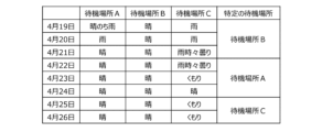
- FIG. 4 is a diagram showing an example of the relationship between weather conditions and specific standby locations on each working day;
- FIG. 27 is a diagram showing an example of a day on which farm work is performed and a specific waiting place to be selected in the example shown in FIG. 26; 4 is a flow chart showing an example of an operation by a management device;
- FIG. 10 is a diagram for explaining an overview of an agricultural management system according to an exemplary second embodiment of the present disclosure;
- FIG. 4 is a flowchart illustrating an example of operations performed by a management device; It is a figure which shows an example of the area
- FIG. 10 is a diagram showing another example of information indicating a guideline for the timing of agricultural work for each region; It is a figure which shows an example of the work plan of each agricultural work. It is a figure which shows an example of the setting screen displayed on a terminal device.
- FIG. 4 is a diagram showing an example of a map referred to when planning a route; FIG.
- agricultural machinery means machinery used in agricultural applications.
- Examples of agricultural machinery include tractors, harvesters, rice transplanters, ride-on tenders, vegetable transplanters, mowers, seeders, fertilizer applicators, agricultural drones, and agricultural mobile robots.
- a working vehicle such as a tractor functions not only as an "agricultural machine” alone, but also as a single “agricultural machine” in which a working vehicle (implement) attached to or towed by the working vehicle and the working vehicle as a whole function.
- Agricultural machines perform farm work such as plowing, sowing, pest control, fertilization, planting of crops, or harvesting on the ground in fields. These agricultural operations are sometimes referred to as “ground operations” or simply “operations.” Traveling while a vehicle-type agricultural machine performs farm work is sometimes referred to as "working travel.”
- “Automated operation” means that the movement of agricultural machinery is controlled by the operation of the control device, not by manual operation by the driver.
- Agricultural machines that operate automatically are sometimes called “automatic driving farm machines” or “robot farm machines”.
- automated driving farm machines not only the movement of the agricultural machine but also the operation of agricultural work (for example, the operation of the working machine) may be automatically controlled.
- the agricultural machine is a vehicle-type machine
- the automatic driving of the agricultural machine is called “automatic driving”.
- the controller may control at least one of the steering, movement speed regulation, movement start and stop necessary for movement of the agricultural machine.
- the control device may control operations such as raising and lowering the work implement and starting and stopping the operation of the work implement.
- Movement by automatic operation may include not only movement of the agricultural machine toward a destination along a predetermined route, but also movement following a tracking target.
- An agricultural machine that operates automatically may move partially based on a user's instruction.
- the agricultural machine that automatically operates may operate in a manual operation mode in which the agricultural machine is moved by manual operation by the driver.
- the act of steering an agricultural machine not by manual operation but by the action of a control device is called "automatic steering".
- Part or all of the controller may be external to the agricultural machine.
- Communication, such as control signals, commands, or data, may occur between a control device external to the agricultural machine and the agricultural machine.
- An agricultural machine that operates automatically may move autonomously while sensing the surrounding environment without a human being involved in controlling the movement of the agricultural machine.
- Agricultural machines capable of autonomous movement can run unmanned inside or outside a field (for example, on roads). Obstacle detection and obstacle avoidance operation may be performed during autonomous movement.
- a "work plan” is data that defines a schedule for one or more farm work to be performed by an agricultural machine.
- a work plan may include, for example, information indicating the order of farm work to be performed by the agricultural machine and the field on which each farm work is to be performed.
- the work plan may include information about the days and times each farm work is scheduled to occur.
- a work plan that includes information on the days and times each farm work is scheduled to be performed is specifically referred to as a "work schedule" or simply a "schedule".
- the work schedule may include information on the scheduled start time and/or the scheduled end time of each farm work to be performed on each work day.
- the work plan or work schedule may include information such as the content of work, the implements used, and/or the types and amounts of agricultural materials used for each agricultural work.
- agricultural material means a material used in agricultural work performed by agricultural machinery. Agricultural materials are sometimes simply referred to as “materials.” Agricultural materials may include materials consumed by agricultural operations, such as pesticides, fertilizers, seeds, or seedlings.
- the work plan may be created by a processing device that communicates with the agricultural machine to manage farm work, or a processing device mounted on the agricultural machine. The processing device can, for example, create a work plan based on information input by a user (a farmer, farm worker, etc.) by operating a terminal device.
- a processing device that communicates with agricultural machines and manages farm work is referred to as a “management device”.
- the management device may manage farm work of a plurality of agricultural machines.
- the management device may create a work plan including information on each farm work performed by each of the plurality of agricultural machines.
- the work plan may be downloaded by each agricultural machine and stored in storage. According to the work plan, each agricultural machine can automatically go to the field and perform the scheduled agricultural work.
- Environmental map is data expressing the position or area of an object existing in the environment in which the agricultural machine moves, using a predetermined coordinate system.
- Environmental maps are sometimes simply referred to as "maps" or “map data”.
- the coordinate system that defines the environment map can be, for example, a world coordinate system, such as a geographic coordinate system fixed with respect to the earth.
- the environment map may include information other than position (for example, attribute information and other information) about objects existing in the environment.
- Environmental maps include various types of maps, such as point cloud maps or grid maps. Local map or partial map data generated or processed in the process of constructing an environment map is also referred to as a "map" or "map data”.
- Global path means the data of the route from the starting point to the destination point when the agricultural machine moves automatically, generated by the processing device that performs the route planning. Generating a global path is called global path planning.
- the global route is also called “target route” or simply “route”.
- a global path may be defined, for example, by coordinate values of points through which the agricultural machine should pass. A point through which the agricultural machine should pass is called a "waypoint”, and a line segment connecting adjacent waypoints is called a "link”.
- Local path means a local path capable of avoiding obstacles, which is sequentially generated when the agricultural machine automatically moves along the global path. Generating a local path is called local path planning. A local route is sequentially generated based on data acquired by one or more sensing devices provided on the agricultural machine while the agricultural machine is moving. A local route may be defined by multiple waypoints along a portion of the global route. However, if an obstacle exists in the vicinity of the global path, waypoints may be set to bypass the obstacle. The length of the links between waypoints in the local path is shorter than the length of the links between waypoints in the global path.
- the device that generates the local route may be the same as or different from the device that generates the global route. For example, a management device that manages farm work by an agricultural machine may generate a global route, and a controller mounted on the agricultural machine may generate a local route.
- a “standby place” is a place set up to stand by while agricultural machinery is not doing farm work.
- One or more waiting locations may be provided in the environment in which the agricultural machine operates autonomously.
- a waiting area can be, for example, a warehouse, garage, barn, parking lot, or other facility.
- a waiting place may be a place jointly managed or used by a plurality of users.
- the holding location may be a warehouse, barn, garage, or parking lot at a farmer's home or business that is different from the agricultural machine user.
- the waiting place may be a place operated by a business operator that provides a service of renting out the self-driving agricultural machine to the user.
- a plurality of waiting locations may be interspersed in the environment in which the agricultural machinery moves. At the standby place, work such as replacement or maintenance of agricultural machinery parts or implements, or replenishment of materials may be performed. In that case, parts, tools, or materials necessary for those operations can be placed in the waiting area.
- the technology of the present disclosure can be applied not only to work vehicles such as tractors, but also to other types of agricultural machines.
- the agricultural machine may be an agricultural drone, or Unmanned Arial Vehicle (UAV).
- UAV Unmanned Arial Vehicle
- Agricultural drones can be used for agricultural operations that can be performed from the air, such as seeding, fertilizing, or pesticide application.
- Agricultural drones may be used for sensing crop growth conditions from the air. Such drones also fall under agricultural machinery in this disclosure.
- FIG. 1 is a diagram for explaining an overview of an agricultural management system according to an exemplary embodiment of the present disclosure.
- the agricultural management system shown in FIG. 1 includes an agricultural machine 100 , a terminal device 400 and a management device 600 .
- the terminal device 400 is a computer used by the user of the agricultural machine 100 .
- the management device 600 is a computer managed by a business operator who operates an agricultural management system.
- Agricultural machine 100 , terminal device 400 , and management device 600 can communicate with each other via network 80 .
- the agricultural management system may include a plurality of agricultural machines.
- the agricultural machine 100 in this embodiment is a tractor.
- Agricultural machine 100 may be a work vehicle other than a tractor or other type of agricultural machine.
- the agricultural machine 100 can be equipped with implements on one or both of the rear and front portions.
- the agricultural machine 100 can travel in a field while performing farm work according to the type of implement.
- the agricultural machine 100 may travel inside or outside a field without the implement attached.
- the agricultural machine 100 has an automatic driving function.
- the agricultural machine 100 can be driven not by manual operation but by the function of the control device.
- the control device in this embodiment is provided inside the agricultural machine 100 and can control both the speed and the steering of the agricultural machine 100 .
- the agricultural machine 100 can automatically travel not only inside the field but also outside the field (for example, roads).
- the agricultural machine 100 includes devices such as GNSS receivers and LiDAR sensors that are used for positioning or self-position estimation.
- the control device of the agricultural machine 100 automatically causes the agricultural machine 100 to travel based on the position of the agricultural machine 100 and the target route information generated by the management device 600 .
- the control device also controls the operation of implements.
- the agricultural machine 100 can perform farm work using the implement while automatically traveling in the field.
- the agricultural machine 100 can automatically travel along the target route on roads outside the field (for example, farm roads or general roads).
- the agricultural machine 100 determines a local route that can avoid obstacles along the target route based on data output from a sensing device such as a camera or a LiDAR sensor. Run while generating. In a field, the agricultural machine 100 may travel while generating a local route in the same manner as described above, or may travel along the target route without generating a local route and an obstacle is detected. You may perform the operation
- the management device 600 is a computer that manages farm work by the agricultural machines 100 .
- the management device 600 may be a server computer that centrally manages information on fields and farm work on the cloud and supports agriculture by utilizing data on the cloud, for example.
- the management device 600 for example, creates a work plan for the agricultural machine 100 and performs global route planning for the agricultural machine 100 according to the work plan.
- the management device 600 generates a global route (target route) using different methods inside and outside the field.
- the management device 600 generates a target route in the field based on information about the field.
- the management device 600 can store the pre-registered external shape of the field, the area of the field, the position of the entrance/exit of the field, the width of the agricultural machine 100, the width of the implement, the content of the work, the type of crops to be cultivated, the growth of the crops, and so on.
- a target path in a field can be generated based on a variety of information, such as area, crop growth, or crop row or furrow spacing.
- Management device 600 generates a target course in a field based on information which a user inputted using terminal device 400 or other devices, for example.
- the management device 600 may generate a route in the field so as to cover the entire work area where work is performed, for example.
- the management device 600 may generate the target route only outside the work area within the field, and may not generate the target route inside the work area.
- the agricultural machine 100 recognizes a row of crops or rows of ridges based on data output from a camera or a LiDAR sensor, and runs while generating a local route along the recognized row of crops or rows of ridges. good.
- the management device 600 generates a target route outside the field according to the work plan.
- the management device 600 can determine the order of farm work indicated by the work plan, the position of the farm field where each farm work is performed, the position of the entrance/exit of the farm field, the scheduled start and end times of each farm work, road surface conditions, weather conditions, or traffic conditions.
- a target route outside the farm field can be generated based on various information such as.
- the management device 600 may further generate and edit an environment map based on data collected by the agricultural machine 100 or other moving bodies using sensing devices such as LiDAR sensors.
- the management device 600 transmits the generated work plan, target route, and environmental map data to the agricultural machine 100 .
- the agricultural machine 100 automatically performs movement and farm work based on those data.
- the global route planning and the generation (or editing) of the environment map are not limited to the management device 600, and may be performed by another device.
- a controller of agricultural machine 100 may perform global route planning or environmental map generation or editing.
- the environment map generating device, the work plan generating device, and the route planning device may be distributed at different locations.
- the terminal device 400 is a computer used by a user remote from the agricultural machine 100 .
- the terminal device 400 shown in FIG. 1 is a laptop computer, but is not limited to this.
- the terminal device 400 may be a stationary computer such as a desktop PC (personal computer), or a mobile terminal such as a smart phone or tablet computer.
- the terminal device 400 displays a setting screen on the display for the user to input information necessary for creating a work plan (for example, a schedule for each farm work) for the agricultural machine 100 .
- a work plan for example, a schedule for each farm work
- Management device 600 creates a work plan based on the information.
- the terminal device 400 may also be used to register one or more fields on which the agricultural machine 100 performs agricultural work.
- FIG. 2 is a side view schematically showing an example of the agricultural machine 100 and the implement 300 connected to the agricultural machine 100.
- the agricultural machine 100 in this embodiment can operate in both manual operation mode and automatic operation mode. In the automatic operation mode, the agricultural machine 100 can run unmanned. The agricultural machine 100 can be automatically operated both inside and outside the field.
- the agricultural machine 100 includes a vehicle body 101, a prime mover (engine) 102, and a transmission (transmission) 103.
- a vehicle body 101 is provided with wheels 104 with tires and a cabin 105 .
- Wheels 104 include a pair of front wheels 104F and a pair of rear wheels 104R.
- a driver's seat 107 , a steering device 106 , an operation terminal 200 , and a group of switches for operation are provided inside the cabin 105 .
- the front wheels 104F and the rear wheels 104R may be equipped with crawlers instead of tires.
- Agricultural machine 100 includes a plurality of sensing devices that sense the surroundings of agricultural machine 100 .
- the sensing device includes multiple cameras 120 , LiDAR sensors 140 and multiple obstacle sensors 130 .
- the cameras 120 may be provided on the front, rear, left, and right of the agricultural machine 100, for example.
- the camera 120 photographs the environment around the agricultural machine 100 and generates image data. Images acquired by the camera 120 can be transmitted to the terminal device 400 for remote monitoring. The image can be used to monitor the agricultural machine 100 during unmanned operation.
- the camera 120 can also be used to generate images for recognizing surrounding features or obstacles, white lines, signs, displays, etc. when the agricultural machine 100 travels on a road outside the field (farm road or general road). can be used.
- the LiDAR sensor 140 in the example of FIG. 2 is arranged at the lower front portion of the vehicle body 101. LiDAR sensor 140 may be provided at other locations. While the agricultural machine 100 is traveling mainly outside the farm, the LiDAR sensor 140 detects the distance and direction to each measurement point of an object present in the surrounding environment, or two-dimensional or three-dimensional coordinate values of each measurement point. Repeatedly outputs sensor data indicating Sensor data output from the LiDAR sensor 140 is processed by the controller of the agricultural machine 100 .
- the control device can estimate the self-position of the agricultural machine 100 by matching the sensor data and the environment map. The control device further detects objects such as obstacles existing around the agricultural machine 100 based on the sensor data, and generates a local route along which the agricultural machine 100 should actually travel along the global route. be able to.
- the controller can also generate or edit an environment map using algorithms such as SLAM (Simultaneous Localization and Mapping).
- the agricultural machine 100 may have multiple LiDAR sensors arranged at different locations and with different orientation
- a plurality of obstacle sensors 130 shown in FIG. 2 are provided at the front and rear of the cabin 105. Obstacle sensors 130 may be placed at other locations as well. For example, one or more obstacle sensors 130 may be provided anywhere on the sides, front, and rear of the vehicle body 101 . Obstacle sensors 130 may include, for example, laser scanners or ultrasonic sonars. The obstacle sensor 130 is used to detect surrounding obstacles and stop or detour the agricultural machine 100 during automatic travel.
- a LiDAR sensor 140 may be utilized as one of the obstacle sensors 130 .
- the agricultural machine 100 further includes a GNSS unit 110.
- GNSS unit 110 includes a GNSS receiver.
- the GNSS receiver may include an antenna that receives signals from GNSS satellites and a processor that calculates the position of agricultural machine 100 based on the signals received by the antenna.
- the GNSS unit 110 receives satellite signals transmitted from multiple GNSS satellites and performs positioning based on the satellite signals.
- GNSS is a general term for satellite positioning systems such as GPS (Global Positioning System), QZSS (Quasi-Zenith Satellite System, eg, Michibiki), GLONASS, Galileo, and BeiDou.
- GPS Global Positioning System
- QZSS Quadasi-Zenith Satellite System
- Galileo Galileo
- BeiDou BeiDou.
- the GNSS unit 110 may include an inertial measurement unit (IMU). Signals from the IMU can be used to supplement the location data.
- the IMU can measure tilts and minute movements of the agricultural machine 100 . Positioning performance can be improved by using data obtained by the IMU to supplement position data based on satellite signals.
- the control device of the agricultural machine 100 may use sensing data acquired by a sensing device such as the camera 120 or the LiDAR sensor 140 for positioning in addition to the positioning result obtained by the GNSS unit 110 .
- a sensing device such as the camera 120 or the LiDAR sensor 140
- the data obtained by the camera 120 or the LiDAR sensor 140 and the previously stored Based on the environment map stored in the device, the position and orientation of the agricultural machine 100 can be estimated with high accuracy.
- the position of the agricultural machine 100 can be specified with higher accuracy.
- the prime mover 102 may be, for example, a diesel engine.
- An electric motor may be used instead of the diesel engine.
- the transmission 103 can change the driving force and the moving speed of the agricultural machine 100 by shifting.
- the transmission 103 can also switch between forward and reverse of the agricultural machine 100 .
- the steering device 106 includes a steering wheel, a steering shaft connected to the steering wheel, and a power steering device that assists steering by the steering wheel.
- the front wheel 104F is a steerable wheel, and the traveling direction of the agricultural machine 100 can be changed by changing the steering angle (also referred to as "steering angle").
- the steering angle of the front wheels 104F can be changed by operating the steering wheel.
- the power steering system includes a hydraulic system or an electric motor that supplies an assist force for changing the steering angle of the front wheels 104F. When automatic steering is performed, the steering angle is automatically adjusted by the power of the hydraulic system or the electric motor under the control of the control device arranged in the agricultural machine 100 .
- a coupling device 108 is provided at the rear portion of the vehicle body 101 .
- the coupling device 108 includes, for example, a three-point support device (also called a "three-point link” or “three-point hitch"), a PTO (Power Take Off) shaft, a universal joint, and a communication cable.
- the implement 300 can be attached to and detached from the agricultural machine 100 by the coupling device 108 .
- the coupling device 108 can change the position or posture of the implement 300 by elevating the three-point link by, for example, a hydraulic device.
- power can be sent from the agricultural machine 100 to the implement 300 via the universal joint.
- the agricultural machine 100 can cause the implement 300 to perform a predetermined work while pulling the implement 300 .
- the connecting device may be provided in front of the vehicle body 101 . In that case, implements can be connected to the front of the agricultural machine 100 .
- the implement 300 shown in FIG. 2 is a rotary tiller, but the implement 300 is not limited to the rotary tiller. Any implement such as seeder, spreader, transplanter, mower, rake, baler, harvester, sprayer, or harrow. It can be used by connecting to the agricultural machine 100 .
- the agricultural machine 100 shown in FIG. 2 is capable of manned operation, but may only be compatible with unmanned operation. In that case, the components required only for manned operation, such as the cabin 105 , the steering device 106 and the driver's seat 107 , may not be provided in the agricultural machine 100 .
- the unmanned agricultural machine 100 can travel autonomously or remotely controlled by a user.
- FIG. 3 is a block diagram showing a configuration example of the agricultural machine 100 and the implement 300. As shown in FIG. Agricultural machine 100 and implement 300 can communicate with each other via a communication cable included in coupling device 108 . Agricultural machine 100 can communicate with terminal device 400 and management device 600 via network 80 .
- the agricultural machine 100 in the example of FIG.
- a communication device 190 an operation switch group 210 , a buzzer 220 and a drive device 240 are provided. These components are communicatively connected to each other via a bus.
- the GNSS unit 110 comprises a GNSS receiver 111 , an RTK receiver 112 , an inertial measurement unit (IMU) 115 and processing circuitry 116 .
- the sensor group 150 includes a steering wheel sensor 152 , a steering angle sensor 154 and an axle sensor 156 .
- Control system 160 includes storage device 170 and control device 180 .
- the controller 180 comprises a plurality of electronic control units (ECUs) 181-186.
- the implement 300 includes a drive device 340 , a control device 380 and a communication device 390 .
- FIG. 3 shows constituent elements that are relatively highly relevant to the automatic operation of the agricultural machine 100, and illustration of other constituent elements is omitted.
- the GNSS receiver 111 in the GNSS unit 110 receives satellite signals transmitted from multiple GNSS satellites and generates GNSS data based on the satellite signals.
- GNSS data is generated in a predetermined format, eg, NMEA-0183 format.
- GNSS data may include, for example, values indicating the identification number, elevation, azimuth, and received strength of each satellite from which the satellite signal was received.
- the GNSS unit 110 shown in FIG. 3 performs positioning of the agricultural machine 100 using RTK (Real Time Kinematic)-GNSS.
- FIG. 4 is a conceptual diagram showing an example of the agricultural machine 100 that performs positioning by RTK-GNSS. Positioning by RTK-GNSS uses correction signals transmitted from the reference station 60 in addition to satellite signals transmitted from a plurality of GNSS satellites 50 .
- the reference station 60 can be installed near the field where the agricultural machine 100 travels (for example, within 10 km from the agricultural machine 100).
- the reference station 60 generates a correction signal, for example in RTCM format, based on the satellite signals received from the plurality of GNSS satellites 50 and transmits it to the GNSS unit 110 .
- RTK receiver 112 includes an antenna and modem to receive correction signals transmitted from reference station 60 .
- the processing circuit 116 of the GNSS unit 110 corrects the positioning result by the GNSS receiver 111 based on the correction signal.
- RTK-GNSS it is possible to perform positioning with an accuracy of, for example, an error of several centimeters.
- Location information including latitude, longitude and altitude information, is obtained through RTK-GNSS high-precision positioning.
- the GNSS unit 110 calculates the position of the agricultural machine 100, for example, at a frequency of about 1 to 10 times per second.
- the positioning method is not limited to RTK-GNSS, and any positioning method (interferometric positioning method, relative positioning method, etc.) that can obtain position information with the required accuracy can be used.
- positioning may be performed using VRS (Virtual Reference Station) or DGPS (Differential Global Positioning System). If position information with required accuracy can be obtained without using the correction signal transmitted from the reference station 60, the position information may be generated without using the correction signal.
- GNSS unit 110 may not include RTK receiver 112 .
- a position of the agricultural machine 100 is estimated.
- the position of agricultural machine 100 may be estimated by matching data output from LiDAR sensor 140 and/or camera 120 with a highly accurate environmental map.
- the GNSS unit 110 in this embodiment further includes an IMU 115 .
- IMU 115 may include a 3-axis accelerometer and a 3-axis gyroscope.
- the IMU 115 may include an orientation sensor, such as a 3-axis geomagnetic sensor.
- the IMU 115 functions as a motion sensor and can output signals indicating various quantities such as acceleration, speed, displacement, and attitude of the agricultural machine 100 .
- Processing circuitry 116 may more accurately estimate the position and orientation of agricultural machine 100 based on signals output from IMU 115 in addition to satellite signals and correction signals. Signals output from IMU 115 may be used to correct or impute positions calculated based on satellite signals and correction signals.
- IMU 115 outputs signals more frequently than GNSS receiver 111 .
- processing circuitry 116 can measure the position and orientation of agricultural machine 100 at a higher frequency (eg, 10 Hz or higher).
- a higher frequency eg, 10 Hz or higher.
- IMU 115 may be provided as a separate device from GNSS unit 110 .
- the camera 120 is an imaging device that captures the environment around the agricultural machine 100 .
- the camera 120 includes an image sensor such as a CCD (Charge Coupled Device) or CMOS (Complementary Metal Oxide Semiconductor). Camera 120 may also include optics, including one or more lenses, and signal processing circuitry.
- the camera 120 captures an image of the environment around the agricultural machine 100 while the agricultural machine 100 is running, and generates image (for example, moving image) data.
- the camera 120 can capture moving images at a frame rate of 3 frames per second (fps) or higher, for example. Images generated by the camera 120 can be used, for example, when a remote observer checks the environment around the agricultural machine 100 using the terminal device 400 .
- the images generated by camera 120 may be used for positioning or obstacle detection.
- a plurality of cameras 120 may be provided at different positions on the agricultural machine 100, or a single camera may be provided. There may be separate visible cameras for generating visible light images and infrared cameras for generating infrared images. Both visible and infrared cameras may be provided as cameras for generating images for surveillance. Infrared cameras can also be used to detect obstacles at night.
- the obstacle sensor 130 detects objects existing around the agricultural machine 100 .
- Obstacle sensors 130 may include, for example, laser scanners or ultrasonic sonars. Obstacle sensor 130 outputs a signal indicating the presence of an obstacle when an object is present closer than a predetermined distance from obstacle sensor 130 .
- a plurality of obstacle sensors 130 may be provided at different positions on the agricultural machine 100 . For example, multiple laser scanners and multiple ultrasonic sonars may be placed at different locations on the agricultural machine 100 . By providing such a large number of obstacle sensors 130, blind spots in monitoring obstacles around the agricultural machine 100 can be reduced.
- a steering wheel sensor 152 measures the rotation angle of the steering wheel of the agricultural machine 100 .
- the steering angle sensor 154 measures the steering angle of the front wheels 104F, which are steered wheels. Measured values by the steering wheel sensor 152 and the steering angle sensor 154 are used for steering control by the controller 180 .
- the axle sensor 156 measures the rotational speed of the axle connected to the wheel 104, that is, the number of revolutions per unit time.
- Axle sensor 156 can be, for example, a sensor utilizing a magnetoresistive element (MR), a Hall element, or an electromagnetic pickup.
- the axle sensor 156 outputs, for example, a numerical value indicating the number of rotations per minute (unit: rpm) of the axle.
- Axle sensor 156 is used to measure the speed of agricultural machine 100 .
- the driving device 240 includes various devices necessary for running the agricultural machine 100 and driving the implement 300, such as the prime mover 102, the transmission 103, the steering device 106, and the coupling device 108 described above.
- Prime mover 102 may comprise an internal combustion engine, such as a diesel engine, for example.
- Drive system 240 may include an electric motor for traction instead of or in addition to the internal combustion engine.
- the buzzer 220 is an audio output device that emits a warning sound to notify an abnormality. Buzzer 220 emits a warning sound when an obstacle is detected, for example, during automatic driving. Buzzer 220 is controlled by controller 180 .
- the storage device 170 includes one or more storage media such as flash memory or magnetic disk.
- Storage device 170 stores various data generated by GNSS unit 110 , camera 120 , obstacle sensor 130 , LiDAR sensor 140 , sensor group 150 , and control device 180 .
- the data stored in the storage device 170 may include map data (environmental map) of the environment in which the agricultural machine 100 travels, and global route (target route) data for automatic driving.
- the environment map includes information on a plurality of farm fields where the agricultural machine 100 performs farm work and roads around the fields.
- the environment map and target route may be generated by a processor in management device 600 .
- the control device 180 in this embodiment has a function of generating or editing an environment map and a target route.
- the control device 180 can edit the environment map and target route acquired from the management device 600 according to the running environment of the agricultural machine 100 .
- the storage device 170 also stores work plan data received by the communication device 190 from the management device 600 .
- a work plan includes information about a plurality of agricultural tasks to be performed by agricultural machine 100 over a plurality of work days.
- the work plan may be, for example, work schedule data including information on the scheduled time of each farm work to be performed by the agricultural machine 100 on each work day.
- the storage device 170 also stores a computer program that causes each ECU in the control device 180 to execute various operations described later.
- Such a computer program can be provided to the agricultural machine 100 via a storage medium (such as a semiconductor memory or an optical disk) or an electric communication line (such as the Internet).
- Such computer programs may be sold as commercial software.
- the control device 180 includes multiple ECUs.
- the plurality of ECUs include, for example, an ECU 181 for speed control, an ECU 182 for steering control, an ECU 183 for implement control, an ECU 184 for automatic driving control, an ECU 185 for route generation, and an ECU 186 for map generation.
- the ECU 181 controls the speed of the agricultural machine 100 by controlling the prime mover 102, transmission 103, and brakes included in the drive device 240.
- the ECU 182 controls the steering of the agricultural machine 100 by controlling the hydraulic system or the electric motor included in the steering system 106 based on the measurement value of the steering wheel sensor 152 .
- the ECU 183 controls the operations of the three-point link and the PTO shaft included in the coupling device 108 in order to cause the implement 300 to perform desired operations. ECU 183 also generates signals that control the operation of implement 300 and transmits the signals from communication device 190 to implement 300 .
- the ECU 184 performs calculations and controls for realizing automatic driving based on data output from the GNSS unit 110, the camera 120, the obstacle sensor 130, the LiDAR sensor 140, and the sensor group 150. For example, ECU 184 identifies the position of agricultural machine 100 based on data output from at least one of GNSS unit 110 , camera 120 , and LiDAR sensor 140 . Within the field, ECU 184 may determine the position of agricultural machine 100 based solely on data output from GNSS unit 110 . The ECU 184 may estimate or correct the position of the agricultural machine 100 based on data acquired by the camera 120 or the LiDAR sensor 140 . By using the data acquired by the camera 120 or the LiDAR sensor 140, the accuracy of positioning can be further improved.
- the ECU 184 uses data output from the LiDAR sensor 140 or the camera 120 to estimate the position of the agricultural machine 100 .
- the ECU 184 may estimate the position of the agricultural machine 100 by matching data output from the LiDAR sensor 140 or the camera 120 with an environmental map.
- the ECU 184 performs calculations necessary for the agricultural machine 100 to travel along the target route or local route based on the estimated position of the agricultural machine 100 .
- the ECU 184 sends a speed change command to the ECU 181 and a steering angle change command to the ECU 182 .
- ECU 181 changes the speed of agricultural machine 100 by controlling prime mover 102, transmission 103, or brakes in response to speed change commands.
- the ECU 182 changes the steering angle by controlling the steering device 106 in response to the command to change the steering angle.
- the ECU 185 sequentially generates local routes that can avoid obstacles while the agricultural machine 100 is traveling on the road along the target route.
- the ECU 185 recognizes obstacles existing around the agricultural machine 100 based on the data output from the camera 120 , the obstacle sensor 130 and the LiDAR sensor 140 while the agricultural machine 100 is running.
- the ECU 185 generates local routes to avoid recognized obstacles.
- the ECU 185 may have a function of global route planning instead of the management device 600 .
- the ECU 185 determines the movement destination of the agricultural machine 100 based on the work plan stored in the storage device 170, and determines the target route from the start point of movement of the agricultural machine 100 to the destination point. Based on the environmental map containing the road information stored in the storage device 170, the ECU 185 can create, for example, a route that can reach the destination in the shortest time as a target route.
- the ECU 186 creates or edits a map of the environment in which the agricultural machine 100 travels.
- an environment map generated by an external device such as the management device 600 is transmitted to the agricultural machine 100 and recorded in the storage device 170, but the ECU 186 can also generate or edit the environment map instead.
- the environmental map may be generated based on sensor data output from the LiDAR sensor 140 .
- the ECU 186 sequentially generates three-dimensional point cloud data based on sensor data output from the LiDAR sensor 140 while the agricultural machine 100 is running.
- the ECU 186 can generate an environment map by connecting the sequentially generated point cloud data using an algorithm such as SLAM, for example.
- the environment map generated in this manner is a highly accurate three-dimensional map and can be used by the ECU 184 for self-position estimation. Based on this 3D map, a 2D map can be generated for use in global route planning.
- the three-dimensional map used for self-localization and the two-dimensional map used for global route planning are both referred to as "environmental maps.”
- the ECU 186 further adds various attribute information related to structures, road conditions, road passability, etc. recognized based on the data output from the camera 120 or the LiDAR sensor 140 to the map. can also be edited.
- the control device 180 realizes automatic operation.
- the control device 180 controls the driving device 240 based on the measured or estimated position of the agricultural machine 100 and the target route. Thereby, the control device 180 can cause the agricultural machine 100 to travel along the target route.
- a plurality of ECUs included in the control device 180 can communicate with each other according to a vehicle bus standard such as CAN (Controller Area Network). Instead of CAN, a higher-speed communication method such as in-vehicle Ethernet (registered trademark) may be used.
- CAN Controller Area Network
- a higher-speed communication method such as in-vehicle Ethernet (registered trademark) may be used.
- An on-board computer that integrates at least some functions of the ECUs 181 to 186 may be provided.
- the control device 180 may include ECUs other than the ECUs 181 to 186, and an arbitrary number of ECUs may be provided according to functions.
- Each ECU includes processing circuitry that includes one or more processors.
- the communication device 190 is a device including circuits for communicating with the implement 300 , the terminal device 400 and the management device 600 .
- Communication device 190 includes circuitry for transmitting and receiving signals conforming to the ISOBUS standard, such as ISOBUS-TIM, to and from communication device 390 of implement 300 .
- the implement 300 can be caused to perform a desired operation, or information can be obtained from the implement 300 .
- Communication device 190 may further include an antenna and communication circuitry for transmitting and receiving signals over network 80 to and from respective communication devices of terminal device 400 and management device 600 .
- Network 80 may include, for example, cellular mobile communication networks such as 3G, 4G or 5G and the Internet.
- the communication device 190 may have a function of communicating with a mobile terminal used by a supervisor near the agricultural machine 100 .
- Communication with such mobile terminals is based on any wireless communication standard, such as Wi-Fi (registered trademark), cellular mobile communication such as 3G, 4G or 5G, or Bluetooth (registered trademark).
- Wi-Fi registered trademark
- cellular mobile communication such as 3G, 4G or 5G
- Bluetooth registered trademark
- the operation terminal 200 is a terminal for the user to execute operations related to running of the agricultural machine 100 and operation of the implement 300, and is also called a virtual terminal (VT).
- Operating terminal 200 may include a display device, such as a touch screen, and/or one or more buttons.
- the display device can be a display such as a liquid crystal or an organic light emitting diode (OLED), for example.
- OLED organic light emitting diode
- the operation terminal 200 the user can perform various operations such as switching the automatic driving mode on/off, recording or editing an environment map, setting a target route, and switching the implement 300 on/off. can be executed. At least part of these operations can also be realized by operating the operation switch group 210 .
- the operating terminal 200 may be configured to be removable from the agricultural machine 100 .
- a user located away from the agricultural machine 100 may operate the removed operation terminal 200 to control the operation of the agricultural machine 100 .
- the user may control the operation of the agricultural machine 100 by operating a computer, such as the terminal device 400, in which necessary application software is installed.
- FIG. 5 is a diagram showing an example of the operation terminal 200 and the operation switch group 210 provided inside the cabin 105.
- FIG. A switch group 210 including a plurality of switches that can be operated by a user is arranged inside the cabin 105 .
- the operation switch group 210 includes, for example, a switch for selecting the gear stage of the main transmission or the sub-transmission, a switch for switching between the automatic driving mode and the manual driving mode, a switch for switching between forward and reverse, and an implement.
- a switch or the like for raising or lowering 300 may be included. Note that if the agricultural machine 100 only operates unmanned and does not have a function of manned operation, the agricultural machine 100 need not include the operation switch group 210 .
- the driving device 340 in the implement 300 shown in FIG. 3 performs operations necessary for the implement 300 to perform a predetermined work.
- Drive device 340 includes a device, such as a hydraulic device, an electric motor, or a pump, depending on the application of implement 300 .
- Controller 380 controls the operation of drive 340 .
- the control device 380 causes the drive device 340 to perform various operations in response to signals transmitted from the agricultural machine 100 via the communication device 390 .
- a signal corresponding to the state of the implement 300 can also be transmitted from the communication device 390 to the agricultural machine 100 .
- FIG. 6 is a block diagram illustrating a schematic hardware configuration of the management device 600 and the terminal device 400. As shown in FIG. 6
- the management device 600 includes a storage device 650 , a processor 660 , a ROM (Read Only Memory) 670 , a RAM (Random Access Memory) 680 and a communication device 690 . These components are communicatively connected to each other via a bus.
- the management device 600 can function as a cloud server that manages schedules of agricultural work in fields performed by the agricultural machines 100 and utilizes managed data to support agriculture.
- the user can use the terminal device 400 to input information necessary for creating a work plan and upload the input information to the management device 600 via the network 80 . Based on the information, the management device 600 can create a schedule for farm work, that is, a work plan.
- Management device 600 is also capable of generating or editing environmental maps and global route planning for agricultural machine 100 . Instead of the management device 600 generating the environment map, the environment map may be distributed from a computer outside the management device 600 .
- the communication device 690 is a communication module for communicating with the agricultural machine 100 and the terminal device 400 via the network 80.
- the communication device 690 can perform wired communication conforming to a communication standard such as IEEE1394 (registered trademark) or Ethernet (registered trademark), for example.
- the communication device 690 may perform wireless communication conforming to the Bluetooth® standard or Wi-Fi standard, or cellular mobile communication such as 3G, 4G or 5G.
- the processor 660 may be, for example, a semiconductor integrated circuit including a central processing unit (CPU).
- Processor 660 may be implemented by a microprocessor or microcontroller.
- the processor 660 is an FPGA (Field Programmable Gate Array) equipped with a CPU, a GPU (Graphics Processing Unit), an ASIC (Application Specific Integrated Circuit), an ASSP (Application Specific Standard Product), or selected from these circuits. It can also be realized by a combination of two or more circuits.
- the processor 660 sequentially executes a computer program describing a group of instructions for executing at least one process stored in the ROM 670 to achieve desired processes.
- the ROM 670 is, for example, a writable memory (eg PROM), a rewritable memory (eg flash memory), or a read-only memory.
- ROM 670 stores programs that control the operation of processor 660 .
- the ROM 670 does not have to be a single storage medium, and may be a collection of multiple storage media. Part of the collection of multiple storage media may be removable memory.
- the RAM 680 provides a work area for temporarily expanding the control program stored in the ROM 670 at boot time.
- the RAM 680 does not have to be a single storage medium, and may be a collection of multiple storage media.
- the storage device 650 mainly functions as database storage.
- Storage device 650 may be, for example, a magnetic storage device or a semiconductor storage device.
- An example of a magnetic storage device is a hard disk drive (HDD).
- An example of a semiconductor memory device is a solid state drive (SSD).
- Storage device 650 may be a device independent of management device 600 .
- the storage device 650 may be a storage device connected to the management device 600 via the network 80, such as a cloud storage.
- the terminal device 400 includes an input device 420 , a display device 430 , a storage device 450 , a processor 460 , a ROM 470 , a RAM 480 and a communication device 490 . These components are communicatively connected to each other via a bus.
- the input device 420 is a device for converting a user's instruction into data and inputting it to the computer.
- Input device 420 may be, for example, a keyboard, mouse, or touch panel.
- Display device 430 may be, for example, a liquid crystal display or an organic EL display. Descriptions of the processor 460, the ROM 470, the RAM 480, the storage device 450, and the communication device 490 are the same as those described in the hardware configuration example of the management device 600, and the description thereof will be omitted.
- the agricultural machine 100 in this embodiment can automatically travel both inside and outside the field.
- the agricultural machine 100 drives the implement 300 to perform a predetermined agricultural work while traveling along a preset target route.
- the obstacle sensor 130 detects an obstacle while traveling in a field
- the agricultural machine 100 stops traveling, emits a warning sound from the buzzer 220, and issues a warning signal to the terminal device 400 or the management device 600.
- and perform operations such as sending Positioning of the agricultural machine 100 in the field is performed mainly based on data output from the GNSS unit 110 .
- the agricultural machine 100 automatically travels along a target route set on a farm road or a general road outside the field.
- the agricultural machine 100 runs while generating a local route based on data acquired by the camera 120 or the LiDAR sensor 140 while running outside the field.
- the agricultural machine 100 avoids the obstacle or stops on the spot.
- the position of the agricultural machine 100 is estimated based on the data output from the LiDAR sensor 140 or the camera 120 in addition to the positioning data output from the GNSS unit 110 .
- FIG. 7 is a diagram schematically showing an example of the agricultural machine 100 automatically traveling along a target route in a field.
- the farm field includes a work area 72 in which the agricultural machine 100 works using the implement 300, and a headland 74 located near the outer edge of the farm field. Which area of the field on the map corresponds to the work area 72 or the headland 74 can be set in advance by the user.
- the target paths in this example include a plurality of parallel main paths P1 and a plurality of turning paths P2 connecting the plurality of main paths P1.
- the main path P1 is located within the working area 72 and the turning path P2 is located within the headland 74 .
- each main path P1 may include a curved portion.
- the main route P1 is, for example, an operation in which the user designates two points (points A and B in FIG. 7) near the edge of the field while looking at the map of the field displayed on the display of the operation terminal 200 or the terminal device 400. It can be automatically generated by doing.
- the management device 600 sets a plurality of main routes P1 parallel to the line segment connecting the point A and the point B specified by the user, and connects the main routes P1 with a turning route P2, thereby making the farm field generate a target path in
- the dashed line in FIG. 7 represents the working width of implement 300 .
- the working width can be set and recorded by the user operating the operation terminal 200 or the terminal device 400 . Alternatively, the working width may be automatically recognized and recorded when implement 300 is connected to agricultural machine 100 .
- the intervals between the main paths P1 can be set according to the working width.
- the target route can be created based on the user's operation before automatic driving is started.
- the target route can be created, for example, so as to cover the entire working area 72 in the field.
- the agricultural machine 100 automatically travels along a target route as shown in FIG. 7 from a work start point to a work end point while repeating reciprocation. Note that the target route shown in FIG. 7 is merely an example, and the method of determining the target route is arbitrary.
- control device 180 Next, an example of control during automatic operation in a field by the control device 180 will be described.
- FIG. 8 is a flowchart showing an example of the steering control operation during automatic driving executed by the control device 180.
- the control device 180 performs automatic steering by executing the operations of steps S121 to S125 shown in FIG. 8 while the agricultural machine 100 is running. As for the speed, it is maintained at a preset speed, for example.
- the control device 180 acquires data indicating the position of the agricultural machine 100 generated by the GNSS unit 110 while the agricultural machine 100 is running (step S121).
- the control device 180 calculates the deviation between the position of the agricultural machine 100 and the target route (step S122). The deviation represents the distance between the position of the agricultural machine 100 at that time and the target route.
- the control device 180 determines whether or not the calculated positional deviation exceeds a preset threshold value (step S123).
- control device 180 changes the steering angle by changing the control parameters of the steering device included in the drive device 240 so that the deviation becomes smaller. If the deviation does not exceed the threshold in step S123, the operation of step S124 is omitted. In subsequent step S125, control device 180 determines whether or not an operation end command has been received.
- An operation end command can be issued, for example, when the user instructs to stop the automatic operation by remote control, or when the agricultural machine 100 reaches the destination. If the operation end command has not been issued, the process returns to step S121, and similar operations are executed based on the newly measured position of the agricultural machine 100.
- FIG. The control device 180 repeats the operations of steps S121 to S125 until an operation end command is issued. The above operations are executed by ECUs 182 and 184 in control device 180 .
- the controller 180 controls the drive 240 based solely on the deviation between the position of the agricultural machine 100 determined by the GNSS unit 110 and the target path, but also takes into account heading deviations. may be controlled. For example, if the orientation deviation, which is the angular difference between the orientation of the agricultural machine 100 identified by the GNSS unit 110 and the direction of the target route, exceeds a preset threshold value, the control device 180 drives according to the deviation.
- a control parameter (eg, steering angle) of the steering system of device 240 may be changed.
- FIG. 9A is a diagram showing an example of the agricultural machine 100 traveling along the target route P.
- FIG. 9B is a diagram showing an example of the agricultural machine 100 at a position shifted to the right from the target path P.
- FIG. 9C is a diagram showing an example of the agricultural machine 100 at a position shifted to the left from the target path P.
- FIG. 9D is a diagram showing an example of the agricultural machine 100 oriented in an oblique direction with respect to the target path P.
- the pose indicating the position and orientation of the agricultural machine 100 measured by the GNSS unit 110 is expressed as r(x, y, ⁇ ).
- (x, y) are coordinates representing the position of the reference point of the agricultural machine 100 in the XY coordinate system, which is a two-dimensional coordinate system fixed to the earth.
- the reference point of the agricultural machine 100 is the position where the GNSS antenna is installed on the cabin, but the position of the reference point is arbitrary.
- ⁇ is an angle representing the measured orientation of the agricultural machine 100 .
- the target path P is parallel to the Y-axis, but in general the target path P is not necessarily parallel to the Y-axis.
- the control device 180 maintains the steering angle and speed of the agricultural machine 100 without changing.
- the control device 180 steers the agricultural machine 100 so that the traveling direction of the agricultural machine 100 is tilted to the left and approaches the path P. change the angle.
- the speed may be changed in addition to the steering angle.
- the magnitude of the steering angle can be adjusted, for example, according to the magnitude of the positional deviation ⁇ x.
- the control device 180 steers the agricultural machine 100 so that the running direction of the agricultural machine 100 is tilted to the right and approaches the path P. change the angle. Also in this case, the speed may be changed in addition to the steering angle. The amount of change in the steering angle can be adjusted, for example, according to the magnitude of the positional deviation ⁇ x.
- the control device 180 performs steering so that the azimuth deviation ⁇ becomes small. change the angle. Also in this case, the speed may be changed in addition to the steering angle.
- the magnitude of the steering angle can be adjusted, for example, according to the respective magnitudes of the position deviation ⁇ x and heading deviation ⁇ . For example, the smaller the absolute value of the positional deviation ⁇ x, the larger the amount of change in the steering angle corresponding to the azimuth deviation ⁇ .
- the absolute value of the positional deviation ⁇ x is large, the steering angle will be greatly changed in order to return to the route P, so the absolute value of the azimuth deviation ⁇ will inevitably become large. Conversely, when the absolute value of the positional deviation ⁇ x is small, it is necessary to make the azimuth deviation ⁇ close to zero. Therefore, it is appropriate to relatively increase the weight (that is, the control gain) of the azimuth deviation ⁇ for determining the steering angle.
- a control technique such as PID control or MPC control (model predictive control) can be applied to the steering control and speed control of the agricultural machine 100 .
- PID control or MPC control model predictive control
- control device 180 stops the agricultural machine 100 . At this time, buzzer 220 may emit a warning sound, or a warning signal may be transmitted to terminal device 400 or management device 600 . If obstacle avoidance is possible, controller 180 may control drive 240 to avoid the obstacle.
- the agricultural machine 100 in this embodiment can automatically travel not only inside the field but also outside the field.
- the control device 180 detects objects (for example, other vehicles, pedestrians, etc.) that are relatively distant from the agricultural machine 100 based on data output from the camera 120 or the LiDAR sensor 140. can do.
- the control device 180 generates a local route to avoid the detected object, and performs speed control and steering control along the local route, thereby realizing automatic driving on the road outside the field.
- FIG. 10 is a diagram schematically showing an example of a situation in which a plurality of agricultural machines 100 are automatically traveling inside a farm field 70 and on roads 76 outside the farm field 70 .
- the storage device 170 records an environmental map of an area including a plurality of farm fields and roads around them, and a target route.
- Environmental maps and target routes may be generated by management device 600 or ECU 185 .
- the agricultural machine 100 travels on the road, the agricultural machine 100 moves along the target route while sensing the surroundings using a sensing device such as the camera 120 and the LiDAR sensor 140 with the implement 300 raised. run.
- the control device 180 sequentially generates local routes and causes the agricultural machine 100 to travel along the local routes. As a result, it is possible to automatically travel while avoiding obstacles.
- the target route may be changed according to the situation.
- a work plan includes information about one or more farm work to be performed by agricultural machine 100 .
- the work plan includes information on one or more farm work to be performed by the agricultural machine 100 and the field in which each farm work is performed.
- the work plan may include information on a plurality of farm work to be performed by the agricultural machine 100 over a plurality of work days and the fields where each farm work is performed.
- the work plan can be a database that includes work schedule information indicating which farm work is to be done in which field at what time for each work day. An example in which the work plan is data of such a work schedule will be described below.
- a work plan can be created by the processor 660 of the management device 600 based on the information input by the user using the terminal device 400 . An example of a work schedule creation method will be described below.
- FIG. 11 is a diagram showing an example of a setting screen 760 displayed on the display device 430 of the terminal device 400.
- the processor 460 of the terminal device 400 activates the application software for schedule creation in response to the user's operation using the input device 420, and causes the display device 430 to display a setting screen 760 as shown in FIG. .
- the user can input information necessary for creating a work schedule.
- FIG. 11 shows an example of the setting screen 760 when plowing accompanied by the application of fertilizer is performed in a rice field as agricultural work.
- the setting screen 760 is not limited to the illustrated one, and can be changed as appropriate.
- the setting screen 760 in the example of FIG. 11 includes a date setting portion 762, a cropping plan selection portion 763, a field selection portion 764, a work selection portion 765, an operator selection portion 766, a time setting portion 767, a machine selection portion 768, and a fertilizer selection portion. 769 , and a spray rate setting portion 770 .
- the date input by the input device 420 is displayed in the date setting portion 762 .
- the input date is set as the farm work implementation date.
- the cropping plan selection portion 763 displays a list of names of cropping plans created in advance. A user can select a desired cropping plan from the list.
- the cropping plan is created in advance for each crop type/variety and recorded in the storage device 650 of the management device 600 .
- the planting plan is a plan of which crops are to be planted in which field (that is, to plant).
- a planting plan is made by a manager or the like who manages a plurality of fields before planting crops in the fields.
- the cropping plan for the rice variety "Koshiibuki" is selected.
- the content set on the setting screen 760 is associated with the planting plan of "Koshiibuki".
- a farm field in the map is displayed in the farm field selection portion 764 .
- the user can select any field from the displayed fields.
- the portion indicating "farm field A” is selected.
- the selected “field A” is set as the field where farm work is performed.
- the work selection portion 765 displays a plurality of agricultural works required for cultivating the selected crops.
- the user can select one agricultural work from a plurality of agricultural works.
- "plowing” is selected from a plurality of agricultural works.
- the selected "tillage” is set as the agricultural work to be performed.
- Pre-registered workers are displayed in the worker selection portion 766 .
- the user can select one or more workers from the displayed plurality of workers.
- "worker B and worker C" are selected among the plurality of workers.
- the selected "worker B, worker C” are set as the workers in charge of implementing or managing the farm work.
- the worker since the agricultural machine automatically performs the farm work, the worker may not actually perform the farm work, but only remotely monitor the farm work performed by the agricultural machine.
- the working time input from the input device 420 is displayed in the time setting portion 767 .
- a working time is specified by a start time and an end time.
- the input work time is set as the scheduled time for the farm work to be performed.
- the machine selection section 768 is a part that sets the agricultural machines used in the farm work.
- the machine selection section 768 can display, for example, the types or models of agricultural machines registered in advance by the management device 600, the types or models of usable implements, and the like. A user can select a particular machine from among the displayed machines. In the example of FIG. 11, an implement whose model is "NW4511" is selected. In this case, the implement is set as the machine used in the agricultural work.
- the names of a plurality of fertilizers registered in advance by the management device 600 are displayed in the fertilizer selection portion 769 .
- the user can select a specific fertilizer from among the displayed multiple fertilizers.
- the selected fertilizer is set as the fertilizer used in the agricultural work.
- a numerical value input from the input device 420 is displayed in the application amount setting portion 770 .
- the entered numerical value is set as the spread amount.
- the communication device 490 of the terminal device 400 manages the input information.
- Processor 660 of management device 600 stores the received information in storage device 650 .
- the processor 660 creates a schedule of agricultural work to be executed by each agricultural machine, and stores the schedule in the storage device 650 .
- the farm work information managed by the management device 600 is not limited to the above.
- the setting screen 760 may be used to set the type and application amount of agricultural chemicals used in the field. Information related to farm work other than the farm work shown in FIG. 11 may be set.
- FIG. 12 is a diagram showing an example of a farm work schedule created by the management device 600.
- the schedule in this example includes, for each registered agricultural machine, information indicating the date and time of farm work, the field, work details, and implements used.
- the schedule may include other information according to the work content, such as the type of agricultural chemical or the amount of agricultural chemical to be applied.
- the processor 660 of the management device 600 issues farm work instructions to the agricultural machine 100 .
- the schedule may also be downloaded by controller 180 of agricultural machine 100 and stored in storage device 170 . In that case, the control device 180 may spontaneously start operating according to the schedule stored in the storage device 170 .
- the work plan is created by the management device 600, but the work plan may be created by another device.
- the processor 460 of the terminal device 400 or the controller 180 of the agricultural machine 100 may have the function of generating or updating the work plan.
- the management device 600 in this embodiment functions as a route planning system for the agricultural machinery 100.
- the storage device 650 stores a map including a plurality of farm fields, a plurality of waiting locations, and roads connecting the plurality of farm fields and the plurality of waiting locations.
- the processor 660 of the management device 600 functions as a processing device that generates the route of the agricultural machine 100 on the map (the above-described global route).
- the management device 600 generates a route of the agricultural machine 100 for each work day based on the work plan. For example, the management device 600 generates a route between fields and a route connecting a farm field and a standby place for each work day according to the schedule of farm work for each work day indicated by the work plan.
- FIG. 13 is a diagram showing an example of a map that is referenced during route planning.
- This map is a two-dimensional digital map and may be generated by management device 600 or other device.
- the map shown in FIG. 13 includes information on the position (for example, latitude and longitude) of each point on a plurality of fields 70 where the agricultural machine 100 performs farm work and on roads 76 around them.
- This map also includes positional information of a plurality of waiting locations 90 where the agricultural machine 100 temporarily waits.
- the waiting place 90 is registered in advance by an administrator of the agricultural management system and recorded in the storage device 650, for example.
- a map such as that shown in FIG. 13 can be created over the area in which the agricultural machine 100 can travel.
- the map shown in FIG. 13 is a two-dimensional map, a three-dimensional map may be used for route planning.
- the waiting place 90 can be, for example, a place shared by a plurality of agricultural machines.
- the waiting place 90 may be, for example, a facility such as a parking lot or a garage managed and operated by a business operating an agricultural management system, an agricultural cooperative, or a municipality. If the waiting place 90 is a facility that is locked at night, it is possible to prevent theft of the agricultural machine stopped at the waiting place 90 . A part of any farm field may be used as the waiting place 90 . Although three waiting places 90 are illustrated in FIG. 13, two or four or more waiting places 90 may be provided.
- the management device 600 reads from the storage device 650 the map of the area including the farm field where the farm work is scheduled to be performed on each work day before the farm work is started on the work day, and based on the map, the route of the agricultural machine 100 ( global routes).
- FIG. 14 is a diagram showing an example of a generated route.
- FIG. 14 exemplifies a field group 70A in which farm work is performed on one work day, a field group 70B in which farm work is performed on the next work day, and a field group 70C in which farm work is performed on the next work day.
- FIG. 14 also illustrates three waiting locations 90A, 90B, 90C for the agricultural machine 100 to wait.
- the farm field groups 70A, 70B, 70C and the standby places 90A, 90B, 90C are drawn relatively close to each other. In reality, the mutual distances between these field groups 70A, 70B, 70C and waiting places 90A, 90B, 90C may be long, for example, 500m to 10km or more.
- the routes generated by the management device 600 are indicated by arrows. Illustration of the route generated in the field is omitted. As described with reference to FIG. 7, the in-field route is generated separately from the out-of-field route.
- the management device 600 generates the entire global route by connecting the route outside the farm field and the route inside the farm field. Solid arrows in FIG. 14 indicate an example of the path of the agricultural machine 100 on a working day. A dashed arrow indicates an example of the path of the agricultural machine 100 in the next working day.
- the management device 600 generates a route from the waiting place 90A as a starting point to the waiting place 90B via the farm field group 70A in order as a route for one work day. This is because the waiting place 90B is the closest waiting place to the field group 70B where farm work is scheduled for the next working day.
- the management device 600 generates, as a route for the next work day, a route starting from the waiting place 90B and sequentially passing through the farm field group 70B and reaching the waiting place 90C. This is because the waiting place 90C is the closest waiting place to the farm field group 70C where farm work is scheduled for the next working day.
- the management device 600 generates a route from the last farm field on each working day to the standby location with the shortest average distance from the group of farm fields on which farm work will be conducted on the next working day. .
- the agricultural machine 100 travels along the generated route.
- the agricultural machine 100 departs from the standby place 90A, sequentially visits the field group 70A scheduled for farm work on that day, and performs the farm work shown in the schedule in each field. Execute. In each field, the agricultural machine 100 performs agricultural work while automatically traveling along the work traveling route, for example, by the method described with reference to FIGS. 7 to 9D. When farm work is completed in one field, the agricultural machine 100 enters the next field and performs farm work in the same way. Thus, when the farm work in the last field of the day is finished, the agricultural machine 100 moves to the waiting place 90A. The agricultural machine 100 waits at the standby place 90A until the next working day.
- the agricultural machine 100 departs from the standby place 90A, sequentially visits the field group 70B scheduled for farm work on that day, and performs the farm work shown in the schedule in each field.
- the agricultural machine 100 moves to the waiting place 90B and waits at the waiting place 90B until the next working day.
- the agricultural machine 100 departs from the waiting place 90B, performs farm work in the field group 70C in order, and then heads to a predetermined waiting place. Through such operations, scheduled farm work can be completed while efficiently moving the agricultural machine 100 along the optimum route according to the schedule.
- the time and fuel consumption required for moving the agricultural machine 100 can be reduced compared to returning to the same location (for example, storage) each time. can.
- a series of farm operations over multiple working days can be streamlined.
- FIG. 15 is a diagram showing an example of global routes generated in a working day.
- the management device 600 generates a route returning from the waiting place 90 to the waiting place 90 via four fields 70 .
- the management device 600 generates a first route 30A within the field 70 and a second route 30B on the road 76 around the field 70 .
- the first route 30A is shown only for the farm field 70 on the lower left, and illustration of the first routes for the other farm fields 70 is omitted.
- the management device 600 generates the first route 30A as indicated by the solid arrow in FIG. 15 inside each field 70 on the map.
- Management device 600 generates first route 30A based on the user's prior settings, as described with reference to FIG.
- the first route 30A can be generated so as to cover the entire work area 72 from the start point S to the end point G while repeating round trips.
- the row spacing in the first path 30A can be determined by considering the width and turning performance of the agricultural machine 100 and the implement 300 .
- the management device 600 generates the first route 30A in the farm field 70 based on the registered information on the farm field 70 .
- the management device 600 generates the first route 30A based on information such as the registered outer shape and area of the agricultural field 70 and the range of the work area 73 and the headlands 74 set by the user.
- the first route 30A can be generated for each field 70, for example, before the agricultural machine 100 starts automatic operation.
- the management device 600 further generates a route from the waiting place 96 to the farm field 70 and a route connecting the plurality of farm fields 70 as the second route 30B.
- the management device 600 generates a second route 30B at the entrance of the farm field 70 in addition to the road 76, and the second route 30B generated at the entrance and the starting point S of the first route 30A.
- the management device 600 also generates a second route 30B at the exit of the field 70, and a fourth route connecting the second route 30B generated at the exit and the end point G of the first route 30A. Generate 30D.
- the entrance and exit of the farm field 70 are common, and are hereinafter referred to as the entrance/exit 71 .
- Each agricultural field 70 may have a plurality of entrances/exits 71, and the entrances and exits may be provided at different locations.
- the environment map also includes positional information of the entrance/exit 71 (or entrance and exit) of each field 70 .
- Management device 600 can generate second route 30B based on the position information.
- the management device 600 generates the third route 30C and the fourth route 30D in areas other than areas where farm work has already been performed in the field 70 . As a result, it is possible to prevent the agricultural machine 100 from trampling the work area 72 in which farm work has already been performed.
- the management device 600 can generate all routes for a predetermined period (for example, half a day, one day, three days, etc.) by executing the above-described route generation processing for each field 70 and the roads 76 around it. For example, on each work day, the management device 600 may generate all routes necessary for completing all farm work scheduled for that work day before the agricultural machine 100 starts running. Alternatively, the management device 600 first generates a route for performing part of the agricultural work scheduled for each working day, and after the part of the agricultural work is completed, the remaining agricultural work for that working day is performed. You may generate a route for Furthermore, the management device 600 may generate all the routes required to complete all farm work scheduled for multiple working days at once. The management device 600 may change the once generated route according to various conditions such as the progress of farm work, weather conditions, traffic conditions, or farm road conditions.
- a predetermined period for example, half a day, one day, three days, etc.
- Management device 600 generates a second route 30B along road 76 according to a predetermined route generation algorithm.
- the management device 600 can generate the second route 30B according to a route generation algorithm based on a search algorithm such as the Dijkstra method or the A * method.
- the management device 600 may automatically generate the second route 30B at a predetermined timing based on the work plan, or may generate the second route 30B according to an instruction from the user.
- the management device 600 may determine the second route 30B according to the state of the road 76 (for example, farm road) leading to the field 70 . For example, if trees grow thickly along the road to the farm field 70 and there is a risk of obstructing reception of radio waves from the GNSS satellites, the management device 600 excludes such a road to generate the second route 30B. may
- the management device 600 can generate a global route from the starting point of the agricultural machine 100 to the terminal point via one or more fields 70 .
- the management device 600 may generate the route of the agricultural machine 100, for example, for each predetermined period (one day, half a day, 3 hours, etc.).
- the management device 600 generates a global route for the agricultural machine 100 according to a pre-created schedule so that the agricultural machine 100 performs farm work in the specified field 70 at the specified time.
- the generated global route information is transmitted to the agricultural machine 100 and recorded in the storage device 170 .
- the ECU 184 that performs automatic operation control controls the ECUs 181 and 182 so that the agricultural machine 100 travels along the global route. Thereby, the agricultural machine 100 starts traveling along the global route.
- the ECU 185 in the control device 180 sequentially generates local routes that can avoid the obstacle while the agricultural machine 100 is running. While the agricultural machine 100 is running, the ECU 185 generates a local route based on sensing data acquired by sensing devices (obstacle sensor 130, LiDAR sensor 140, camera 120, etc.) provided in the agricultural machine 100. do. A local route is defined by multiple waypoints along a portion of the global route. The ECU 185 determines whether there is an obstacle on or near the path of the agricultural machine 100 based on the sensing data.
- the ECU 185 sets multiple waypoints to generate a local route to avoid the obstacles. If no obstacles are present, the ECU 185 generates a local path approximately parallel to the global path. Information indicating the generated local route is sent to the ECU 184 for automatic operation control. ECU 184 controls ECU 181 and ECU 182 so that agricultural machine 100 travels along a local route. As a result, the agricultural machine 100 can travel while avoiding obstacles. Note that when there is a traffic light on the road on which the agricultural machine 100 travels, the agricultural machine 100 recognizes the traffic light based on the image captured by the camera 120, stops at a red light, and starts at a green light. you can go
- FIG. 16 is a diagram showing an example of global routes and local routes generated in an environment with obstacles.
- a global route 30 is illustrated by dotted line arrows, and a local route 32 that is sequentially generated during travel is illustrated by solid line arrows.
- a global path 30 is defined by a plurality of waypoints 30p.
- the local path 32 is defined by a plurality of waypoints 32p set at shorter intervals than the waypoints 30p.
- Each waypoint for example, has position and orientation information.
- the management device 600 generates the global route 30 by setting multiple waypoints 30p at multiple locations including intersections of the road 76 .
- the distance between the waypoints 30p may be relatively long, for example, several meters to several tens of meters.
- the ECU 185 generates the local route 32 by setting a plurality of waypoints 32p based on the sensing data output from the sensing device while the agricultural machine 100 is running.
- the spacing of waypoints 32p on local path 32 is less than the spacing of waypoints 30p on global path 30 .
- the distance between the waypoints 32p can be, for example, on the order of tens of centimeters (cm) to several meters (m).
- the local route 32 is generated within a relatively narrow range (for example, a range of several meters) starting from the position of the agricultural machine 100 .
- FIG. 16 illustrates a series of local paths 32 generated while agricultural machine 100 travels along road 76 between fields 70 and makes a left turn at an intersection.
- the ECU 185 repeats the operation of generating a local route from the position of the agricultural machine 100 estimated by the ECU 184 to a point several meters ahead, for example.
- the agricultural machine 100 travels along the sequentially generated local routes.
- FIG. 16 illustrates an example of a range sensed by a sensing device such as the camera 120, the obstacle sensor 130, or the LiDAR sensor 140 mounted on the agricultural machine 100 in a fan shape.
- the ECU 185 generates the local route 32 to avoid the detected obstacles 40 based on the sensing data.
- the ECU 185 detects the possibility of the agricultural machine 100 colliding with the obstacle 40 based on the sensing data and the width of the agricultural machine 100 (including the width of the implement if the implement is attached).
- the ECU 185 sets a plurality of waypoints 32 p to avoid the obstacle 40 and generates the local route 32 .
- the ECU 185 recognizes not only the presence or absence of obstacles 40 but also the state of the road surface (for example, muddy, depression, etc.) based on sensing data.
- Local paths 32 may be generated to avoid.
- Agricultural machine 100 travels along local path 32 .
- the controller 180 may stop the agricultural machine 100 .
- the control device 180 may send a warning signal to the terminal device 400 or the management device 600 to alert the observer. After stopping, the control device 180 may resume traveling of the agricultural machine 100 when it recognizes that the obstacle 40 has moved and the risk of collision has disappeared.
- FIG. 17 is a diagram showing an example of a map of an area where agricultural machinery performs farm work.
- the map shown in FIG. 16 is an explanatory map created by processing an aerial photograph created by the Geospatial Information Authority of Japan. Maps that are actually used are not necessarily based on aerial photographs created by the Geospatial Information Authority of Japan, and may have any data format.
- a map is generated and recorded in the storage device 650 throughout the area over which the agricultural machine travels.
- the map shown in FIG. 17 includes information on the position (for example, latitude and longitude) of each point on a plurality of fields 70, a plurality of waiting places 90, and roads 76 around them.
- the position of the waiting place 90 is indicated by a .DELTA. mark.
- the waiting place 90 can be a facility such as a warehouse, a garage, or a parking lot managed by a business operator who operates an agricultural management system, for example. A part of any farm field may be used as the waiting place 90 .
- Each agricultural machine automatically operates under the control of the management device 600 and performs its assigned agricultural work.
- the map is created in advance so as to cover the entire area where all agricultural machines operated under the management of the management device 600 move.
- Each agricultural machine may be, for example, a tractor such as the agricultural machine 100 described above, or other types of agricultural vehicles such as rice transplanters, combine harvesters, vegetable harvesters, or agricultural drones. good too.
- FIG. 17 illustrates five waiting locations 90.
- the waiting places 90 can be set, for example, at intervals of several hundred meters to several kilometers.
- the number and distribution of waiting places 90 are determined according to various conditions such as the number of agricultural machines in operation, the distribution of fields 70, the size of the area in which the agricultural machines are operated, and the road traffic environment.
- the waiting place 90 is registered by, for example, an administrator of the agricultural management system. Positional information of each waiting place 90 and information indicating a field group corresponding to each waiting place 90 are recorded in the storage device 650 in advance.
- the management device 600 controls each agricultural machine to be operated last on each work day based on information indicating at least one of the growth status of crops, the progress status of agricultural work, the planting status, and the weather status in a plurality of fields 70 .
- a specific waiting place to be moved to after performing the farm work is determined from among a plurality of waiting places 90. - ⁇
- the management device 600 generates a route from the field where the last agricultural work is performed on the working day to the specific standby place.
- the specific waiting place to which the agricultural machinery goes after performing the last farm work in each work day can be appropriately determined according to various conditions such as the growth state of the crop, the progress of the farm work, the planting state, or the weather condition. can be selected.
- the management device 600 in this embodiment monitors at least one of the crop growth status, farm work progress status, planting status, and weather status in each field.
- the management device 600 When generating a route for each work day of the agricultural machine, the management device 600 generates a route after work on the work day based on at least one of the crop growth status, farm work progress status, planting status, and weather conditions. Decide where to wait.
- the management device 600 determines the distribution of working days in the fields located around each of the plurality of standby locations based on at least one of the crop growth status, farm work progress status, planting status, and weather conditions. do.
- the management device 600 determines a specific standby location to which the agricultural machine will go after performing the last agricultural work in each working day. For example, when determining a specific standby location for each work day, the management device 600 selects a group of fields on which farm work will be performed on the next work day based on the distribution of work days in the fields located around each standby location. A waiting place closest to the field group may be determined as the specified waiting place.
- the standby location closest to the field group means the standby location having the smallest average linear distance or moving distance from the plurality of fields included in the field group among the plurality of standby locations. Such an operation shortens the distance traveled by the agricultural machine, shortening travel time, and reducing fuel consumption.
- FIG. 18 is a diagram showing an example of a table showing an example of correspondence between waiting places and fields.
- fields #1 to #100 out of 100 fields (fields #1 to #100), fields #1 to #30 are associated with waiting place A, fields #31 to #60 are associated with waiting place B, and field # 61 to #100 are associated with the waiting place C.
- the farm field is expressed as "belonging" to the waiting place.
- the standby location closest to the fields #1 to #30 is the standby location A
- the standby location closest to the fields #31 to #60 is the standby location B
- the field #61 is the standby location closest to the fields #31 to #60.
- ⁇ #100 can be generated if the closest waiting location is waiting location C.
- the management device 600 can determine a waiting place close to a field group where farm work scheduled for the next working day will be performed. Note that the table shown in FIG. 18 is an example, and the number of waiting locations is not limited to three, and may be four or more. Also, the number of farm fields associated with each waiting place is arbitrary and is not limited to the illustrated number. This point also applies to subsequent figures.
- FIG. 19 is a diagram showing an example of a map that clearly shows the correspondence between waiting places and fields.
- the farm field group 70A belonging to the waiting place 90A, the farm field group 70B belonging to the waiting place 90B, and the farm field group 70C belonging to the waiting place 90C are shown in different patterns.
- each field in which farm work is automatically performed by the agricultural machine 100 is associated with one standby location relatively close to the field.
- each field does not necessarily have to be associated with the nearest waiting place. It may be better to group neighboring fields together according to attributes such as the crop planted or the owner.
- a group of fields, rather than individual fields may be associated with one waiting location. In such a form, some fields in the group may be associated with a waiting place different from the nearest waiting place (for example, the second closest waiting place).
- the management device 600 in this embodiment generates a work plan, for example, as illustrated in FIG. 12, for each agricultural machine based on data acquired from one or more users. Based on the work plan, the management device 600 determines the route of each agricultural machine for each work day, and instructs each agricultural machine to move along the route and perform the farm work.
- the work plan defines the distribution of work days in a plurality of fields in which each agricultural machine works.
- the management device 600 determines a specific standby location to which each agricultural machine moves after finishing farm work on each work day, according to the distribution of work days indicated by the work plan.
- the management device 600 In determining a specific standby place, the management device 600 refers to information (for example, data such as a table) indicating various conditions such as crop growth conditions, agricultural work progress conditions, planting conditions, and weather conditions in each field. do.
- the management device 600 updates the work plan according to these situations, and determines the standby location and route of the agricultural machine for each work day according to the distribution of work days indicated by the updated work plan.
- the management device 600 confirms these situations, for example, for each work day or at fixed time intervals, corrects the work plan according to the situation, and determines a standby place for each work day according to the corrected work plan.
- FIG. 20 is a diagram showing an example of a table for managing the growth status of crops in each field.
- This table contains information about crop growth conditions (for example, average plant height) and scheduled working days in each field. Data about crop growth can be obtained by mobiles such as drones equipped with LiDAR sensors or cameras, for example.
- the growth status is not limited to the plant height of crops, and may be expressed by other indices such as the vegetation index.
- the management device 600 determines the scheduled working days for farm work such as harvesting in each field according to the growth status of crops in each field, and writes the dates into the table. For example, the management device 600 determines the working days of each field so that the earlier the crop grows in the field, the earlier the work is performed. In the example shown in FIG.
- the management device 600 advances the work days for the fields #31 to #60 belonging to the standby location B and delays the work days for the fields #61 to #100 belonging to the standby location C.
- the table shown in FIG. 20 includes information indicating which standby location each field corresponds to, but this information may be omitted. As shown in FIG. 18, when the correspondence between farm fields and standby locations is recorded in a separate table, the table shown in FIG. 20 may not include standby location information. This point also applies to subsequent figures.
- FIG. 21 is a table showing an example of the distribution of working days for a plurality of fields in the growth situation shown in FIG.
- the management device 600 tallies the number of fields in which farm work is performed among the fields belonging to each standby place for each working day. For example, the management device 600 determines, for each working day, the standby location with the largest number of fields around which farm work is performed as the specific standby location to which the agricultural machine is headed after the last farm work of the day is completed. In the example of FIG. 21, the management device 600 sets the standby location B from September 1st to September 5th, the standby location A from September 6th to September 10th, and the standby location A from September 11th to September 11th. Until the 15th, the waiting place C is determined as a specific waiting place.
- the management device 600 updates the distribution of working days according to the growth status of crops in a plurality of fields, and based on the updated distribution of working days, each Determine specific waiting areas for the working day.
- the work days for each field it is possible to set the work days for each field so that, for example, the farm work is performed in order from the field where the crops grow quickly, and the total moving distance of the agricultural machinery is shortened, so that the farm work can be performed more efficiently. becomes possible.
- FIG. 22 is a diagram showing an example of a table for managing the progress of farm work in each field.
- This table contains information on the progress and scheduled work dates of specific farm work in each field.
- the progress can be represented, for example, by status information indicating whether the farm work has already been completed at that time.
- the farm work is tillage, and the progress is represented by statuses such as "Untilled" or "Tilled”.
- the management device 600 determines the scheduled work date for the field whose progress status is "Untilled” and writes the information into the table.
- the management device 600 periodically (for example, every day) determines the working days from the next day onwards for the fields that have not yet been tilled, and updates the table.
- FIG. 22 contains information on the progress and scheduled work dates of specific farm work in each field.
- the progress can be represented, for example, by status information indicating whether the farm work has already been completed at that time.
- the farm work is tillage, and the progress is represented by statuses such as "Untilled
- the work in the fields #61 to #100 near the standby location C has already been completed.
- the work days can be determined so that the remaining unfinished fields will be worked on, for example, in order from the field closest to the position of the agricultural machine at that point in time.
- the progress status is changed from "unplowed" to "plowed".
- the progress status can be changed automatically based on information such as a work completion notification sent from the agricultural machine, for example.
- FIG. 23 is a diagram showing an example of the distribution of working days in a plurality of fields corresponding to the example shown in FIG.
- the management device 600 determines, for each work day, a standby location having the largest number of farm fields around which farm work is performed as a specific standby location. In this example, on April 19th and April 20th, agricultural work is scheduled only in the fields belonging to the waiting place B, so the waiting place B is determined as the specific waiting place. On April 21 and April 22, agricultural work is scheduled only in the fields belonging to the standby location A, so the standby location A is determined as the specific standby location. Even after the distribution of work days is determined in this way, there are cases where the work does not proceed as planned and the progress of the work is behind schedule. In that case, the management device 600 updates the progress and corrects the working days in each field based on the updated progress.
- the management device 600 updates the distribution of work days according to the progress of farm work in a plurality of fields, and updates the distribution of work days based on the updated distribution of work days. Determine specific waiting areas for the working day. This makes it possible to determine an appropriate waiting place and optimize the route plan according to the progress of farm work, for example. As a result, the total travel distance of the agricultural machine can be shortened, making it possible to perform farm work more efficiently.
- FIG. 24 is a diagram showing an example of a correspondence relationship between planting information and the number of fields belonging to each standby location.
- the planting information represents, for example, varieties of crops to be planted.
- rice varieties such as "Koshihikari A”, “Koshihikari B”, and “Hinohikari” are recorded as cropping information.
- the management device 600 determines the days of work in each field so that the farm work in the fields planted with the same variety of crops is concentrated in a short period of time.
- FIG. 24 is a diagram showing an example of a correspondence relationship between planting information and the number of fields belonging to each standby location.
- the planting information represents, for example, varieties of crops to be planted.
- rice varieties such as "Koshihikari A”, “Koshihikari B”, and "Hinohikari” are recorded as cropping information.
- the management device 600 determines the days of work in each field so that the farm work in the fields planted with the same variety of crops is concentrated in a short period of time.
- FIG. 25 is a diagram showing the distribution of working days in a plurality of fields corresponding to the example shown in FIG.
- the management device 600 determines the working days for each field so that the agricultural machine moves in the order of the field group belonging to the waiting place B, the farm field group belonging to the waiting place A, and the farm field group belonging to the waiting place C. do.
- the management device 600 designates the standby location B from April 19th to April 21st, the standby location A from April 22nd to April 27th, and the standby location A from April 28th to May 3rd. determines waiting place C as a particular waiting place.
- the management device 600 updates the distribution of working days according to the cropping conditions in a plurality of fields, and updates each working day based on the updated distribution of working days. determine specific waiting areas in As a result, for example, when it is necessary to perform agricultural work intensively in a short period of time in a field planted with crops of the same variety, it is possible to determine appropriate waiting locations and optimize route planning. As a result, it becomes possible to shorten the total travel distance of the agricultural machine and perform farm work more efficiently.
- FIG. 26 is a diagram showing an example of the relationship between weather conditions and specific waiting locations on each work day.
- parking locations A, B, and C are separated from each other by varying weather conditions.
- the management device 600 acquires the weather data of the point where each waiting place is located from a server computer that distributes weather data via a network such as the Internet.
- a network such as the Internet.
- the management device 600 performs farm work first in the field around the waiting place B, then in the field around the waiting place A, and then in the field around the waiting place C. The work day in each field is determined so that farm work can be done.
- FIG. 27 is a diagram showing an example of days when farm work (plowing in this example) is performed and specific waiting places to be selected in the example shown in FIG.
- the fields around the waiting place B are plowed, so the waiting place B is selected as the specific waiting place.
- the fields around the waiting place A are plowed, so the waiting place A is selected as the specific waiting place.
- the waiting place C is selected as the specific waiting place because the fields around the waiting place C are plowed.
- the management device 600 updates the distribution of working days according to the weather conditions at the points where the plurality of standby places are respectively located, and updates the distribution of the updated working days.
- the management device 600 determines a specific standby location according to any of the crop growth status, farm work progress status, planting status, and weather conditions in each field. Instead of such an operation, the management device 600 may determine a specific standby location based on any two or more of the growing conditions of crops, the progress of agricultural work, planting conditions, and weather conditions. . Composite consideration of these situations enables more appropriate route planning according to the situation, making it possible to further improve the efficiency of operation of agricultural machinery.
- the management device 600 is positioned around each standby location based on at least one of the growth status of crops in a plurality of fields, the progress status of farm work, the planting status, and the weather conditions. Determine the distribution of working days in the field. Based on the distribution of working days, the management device 600 determines a specific waiting location to which the agricultural machine moves after performing the last agricultural work in each working day. For example, when determining a specific standby location for each work day, the management device 600 identifies a field group where farm work will be performed on the next work day based on the distribution of work days, A location may be determined as a specific waiting location.
- the management device 600 may determine the standby location closest to the first field where the last farm work is performed on the work day as the specific standby location. . That is, the management device 600 selects the standby location closest to the first field where the last farm work is performed on the work day, or the second field where the farm work is first performed on the next work day specified from the work day distribution. may be determined as the particular waiting location. If the waiting place closest to the first field and the waiting place closest to the second field are different, the management device 600 selects the waiting place closest to the first field and the waiting place closest to the second field. A waiting place with a shorter movement distance when moving from the first field to the second field via the waiting place may be determined as the specific waiting place. As a result, it is possible to shorten the travel distance and the travel time between the farm field and the standby place, so that efficient operation becomes possible while suppressing fuel consumption.
- FIG. 28 is a flowchart showing an example of operations by the management device 600 in this embodiment.
- the management device 600 can perform global route planning for the agricultural machinery on a certain working day and allow the agricultural machinery to perform automatic operation.
- the operation of route planning shown in FIG. 28 can be performed at any timing before starting the movement of the agricultural machine.
- the route planning may be performed immediately before the start of movement of the agricultural machine, or may be performed on or before the day before the start of movement.
- the management device 600 acquires information indicating at least one of the growth status of crops, the progress status of farm work, the planting status, and the weather status in each field.
- the information may be managed by the management device 600 itself, or may be managed by a device different from the management device 600 .
- the growth status of crops, the progress status of farm work, the planting status, and the weather conditions may be distributed and managed by a plurality of devices.
- the information acquired here can be, for example, information as shown in FIG. 20, FIG. 22, FIG. 24, and/or FIG.
- step S142 the management device 600 determines a specific standby location to which the agricultural machine will move after performing the last agricultural work on the working day. For example, based on the information acquired in step S141, the management device 600 determines the first field group where farm work is to be performed on the working day, and designates the first waiting place closest to the first field group as the specific waiting place. may decide. Alternatively, based on the information acquired in step S141, the management device 600 determines the second field group where farm work will be performed on the next working day, and designates the second waiting place closest to the second field group as the specified waiting place. may be determined as If the first standby location and the second standby location are different, the management device 600 may select, as the specific standby location, either the first standby location or the second standby location, whichever has the shorter travel distance of the agricultural machine. good.
- step S143 the management device 600 generates a route for the working day. That is, the management device 600 generates a global route from the standby location, which is the departure point on the work day, to the standby location determined in step S142 via one or more fields where farm work is performed on that day. .
- This route can be determined, for example, to minimize the total travel distance of the agricultural machine.
- step S144 the management device 600 transmits a movement command including information on the generated route to the agricultural machine.
- this movement command may also include schedule information indicating, for example, at what time and in which field the farm work should be performed.
- the control device of the agricultural machine starts automatic operation at the designated time and moves along the designated route. The agricultural machine moves while generating a local path that can avoid obstacles, for example, by the method described with reference to FIG.
- the management device 600 can generate the route of the agricultural machine in a working day.
- the management device 600 can generate a route of the agricultural machine for each working day and instruct the agricultural machine to move, for example, by executing the operation shown in FIG. 28 for each working day.
- the management device 600 may perform the operation shown in FIG. 28 again to correct the route or the waiting place. For example, a sudden change in weather may make it impossible to carry out an originally planned work while the agricultural machine is moving. Even in such a case, by performing the operation shown in FIG. 28 (for example, at regular time intervals) after starting movement, it is possible to appropriately change the waiting place and route.
- the management device 600 in the above embodiment generates routes for each work day for a plurality of agricultural machines.
- the management device 600 controls each work day based on information indicating at least one of the growth status of crops in a plurality of fields, the progress status of farm work in a plurality of fields, the cropping status in a plurality of fields, and the weather conditions. determines a specific waiting place from among a plurality of waiting places to which each agricultural machine moves after performing the last agricultural work.
- the management device 600 generates a route from the field where the last agricultural work is performed to a specific standby place for each agricultural machine. This makes it possible to determine the optimum route that minimizes the total travel distance for each agricultural machine.
- the number of agricultural machines is not limited to a plurality, and the number may be one.
- FIG. 29 is a diagram for explaining an overview of an agricultural management system according to the exemplary second embodiment of the present disclosure.
- the agricultural management system shown in FIG. 29 includes a plurality of agricultural machines 100 and a management device 600.
- FIG. 29 also shows a plurality of terminal devices 400 used by a plurality of users.
- the management device 600 is a computer managed by a business operator who operates an agricultural management system.
- Each agricultural machine 100 and each terminal device 400 can communicate with the management device 600 via the network 80 .
- the agricultural management system may include two or fewer or four or more agricultural machines 100 .
- Agricultural management systems may include a plurality of different types of agricultural machinery, such as, for example, tractors, rice planters, combines, and/or agricultural drones.
- Each agricultural machine 100 performs its assigned agricultural work in a designated field according to instructions from the management device 600 .
- the agricultural management system shown in FIG. 1 can be used, for example, as a substitute service for agricultural work using a plurality of agricultural machines 100 that operate automatically.
- each of a plurality of agricultural machines 100 is controlled to move between a plurality of fields managed by a plurality of users who are contractors, and to perform designated agricultural work in designated fields.
- the management device 600 creates a work plan for each agricultural machine 100 based on information indicating a rough plan for farm work input by each user using each terminal device 400, and creates a work plan for each agricultural machine 100 based on the work plan. Route planning may be performed.
- management device 600 may perform processing about billing to each user.
- the management device 600 may be a collection of multiple computers.
- the management device 600 may include a computer that creates a work plan for each agricultural machine 100, a computer that plans a route for each agricultural machine 100, and a computer that charges each user.
- Agricultural work agency services such as those described above can be provided over a wide area, such as a country, state, region, prefecture, or an area spanning multiple countries.
- the area served may include multiple areas with different climates or weather conditions.
- Weather conditions such as temperature, humidity, precipitation, and amount of sunshine can vary from region to region.
- the times at which individual agricultural operations for example, tillage, sowing, planting, pest control, fertilization, harvesting, etc.
- the management device 600 in the present embodiment acquires information indicating a guideline for the timing of agricultural work for each region, which is recorded in the storage device in advance, and based on the information, each agricultural machine 100 performs farm work in each region.
- the information indicating the approximate timing of agricultural work can be created for each type of agricultural work, such as plowing, sowing, planting, pest control, fertilization, or harvesting.
- the management device 600 determines the route that each agricultural machine 100 should move such that each agricultural machine 100 performs a predetermined agricultural work at the time determined for each region.
- the management device 600 refers to the map of the area where each agricultural machine 100 moves, generates a route on the map for each agricultural machine 100 to move, and transmits the route information to each agricultural machine 100 .
- Each agricultural machine 100 moves based on the received route information and performs a predetermined agricultural work in the field assigned to each.
- Each agricultural machine 100 has the same configuration as the agricultural machine 100 in the first embodiment.
- Each agricultural machine 100 can travel inside and outside a field (for example, a road) by automatic operation.
- the terminal device 400 is a computer used by a user remote from the agricultural machine 100 .
- the terminal device 400 may be a mobile terminal such as a laptop computer, a smart phone, or a tablet computer as shown in FIG. 29, or a stationary computer such as a desktop PC.
- Each terminal device 400 displays a setting screen on the display for the user to input information necessary for creating a work plan (for example, a schedule for each farm work).
- the terminal device 400 transmits the input information to the management device 600 .
- Management device 600 creates a work plan based on the information.
- the terminal device 400 may also be used to register one or more fields on which the agricultural machine 100 performs agricultural work.
- the management device 600 functions as a route planning system for each agricultural machine 100 that automatically operates across multiple regions.
- Storage device 650 stores a map of an area that includes multiple regions. For example, storage device 650 stores a map of a relatively large area that includes multiple regions with different climates or weather conditions.
- the processor 660 of the management device 600 functions as a processing device that generates the route (the global route described above) of each agricultural machine 100 on the map.
- FIG. 30 is a flowchart outlining the operations performed by the management device 600.
- the storage device 650 records in advance information indicating a rough estimate of the timing of agricultural work to be performed by each agricultural machine 100 for each region.
- the management device 600 acquires the information from the storage device 650 (step S241). Based on the information, the management device 600 determines when each agricultural machine 100 performs farm work in each of the plurality of regions (step S242).
- the management device 600 generates a route for each agricultural machine 100 on the map so that each agricultural machine 100 performs the farm work at the time determined for each region (step S243).
- the management device 600 determines a plurality of work days on which each agricultural machine 100 performs the farm work at the time determined for each region, and generates a route for each agricultural machine 100 on each work day.
- the management device 600 transmits a movement command including information on the generated route to each agricultural machine 100 (step S244).
- this movement command may also include schedule information indicating, for example, at what time and in which field the farm work should be performed.
- the control device 180 of each agricultural machine 100 starts automatic operation at the specified time, moves the agricultural machine 100 along the specified route, and causes the farm work to be performed in the field. .
- FIG. 31 is a diagram showing an example of a region in which the agricultural machine 100 moves.
- each agricultural machine 100 moves over a wide area in Japan for a relatively long period of time (for example, several weeks to several months or longer) and performs farm work in fields in each region.
- the area where the agricultural machine 100 performs farm work is divided into eight areas A to H.
- FIG. Area A is located furthest south, followed by areas B, C, D, E, F, and G, which are generally distributed from south to north in that order, and area H is located furthest north.
- Each region shown in FIG. 31 has an area of 10,000 square kilometers (km 2 ) to 100,000 km 2 and may include 1000 or more fields. Each region can be larger or smaller than this example. Each region may, for example, have an area of 30 km 2 or more and/or 100 or more fields. Two adjacent regions are accessible to each other via a road.
- an agricultural land that is surrounded by paths such as ridges or farm roads is defined as one agricultural field.
- Each field can be, for example, a field, paddy field, orchard, or pasture.
- FIG. 32 is a diagram showing an example of information indicating a guideline for the timing of agricultural work for each region in the example shown in FIG.
- the information indicating the approximate timing of agricultural work for each region can be created in the form of a table as shown in FIG. 32, for example.
- the table shown in FIG. 32 shows a guideline (for example, a recommended time) of the work period in each region for a certain agricultural work.
- Such a table can be created for each type of farm work, and recorded in the storage device 650, for example.
- the management device 600 in the present embodiment determines the timing for each agricultural machine 100 to perform agricultural work in each region based on information indicating the approximate timing of agricultural work for each region, as illustrated in FIG. 32 . do.
- the management device 600 generates a route for each work day for each agricultural machine 100 so that each agricultural machine 100 performs the farm work at the time determined for each region.
- the management device 600 creates a work plan for each agricultural machine 100 over a plurality of work days based on the information indicating the approximate timing of agricultural work for each region, and performs each work for each agricultural machine 100 according to the work plan.
- a route in days may be generated.
- Each agricultural machine 100 moves along the generated route and performs farm work in each field indicated by the work plan.
- Each agricultural machine 100 may automatically travel on roads including public roads in order to move between regions.
- the information indicating the estimated timing of agricultural work for each region indicates that the northern region tends to have later agricultural work.
- the management device 600 determines when the agricultural machine 100 performs farm work in each region so as to gradually move the agricultural machine 100 north as the days pass, according to the trend.
- the information indicating the approximate timing of agricultural work for each region shows a tendency that the closer to the south the region is, the later the timing of agricultural work. For example, in the Southern Hemisphere, in general, regions located in the north are warmer, regions located in the south are colder, and regions located in the south tend to have later agricultural work.
- the management device 600 may determine the timing for the agricultural machine 100 to perform the farm work in each region so as to gradually move the agricultural machine 100 southward as the days pass according to the trend. good. In this way, the management device 600 generates a route for each work day for each agricultural machine 100 so that the agricultural machine 100 gradually moves from an area with a relatively high temperature to an area with a lower temperature in accordance with changes in temperature. You may
- a zone with a climate or meteorological conditions suitable for agricultural work at a certain time will be called a "work front" after comparing it to a front in weather.
- the work front generally moves from south to north as the day progresses.
- the work front does not necessarily show such a simple transition in many cases.
- climate can vary not only by latitude, but also by various geographical conditions such as altitude, topography, and degree of monsoon influence.
- the working front does not generally move simply from south to north or north to south. Even in such a case, it is possible to carry out farm work in each region at an appropriate time by appropriately creating information indicating a guideline for the timing of farm work for each region.
- the information indicating the approximate timing of agricultural work for each region can be created based on information such as the recommended timing for each agricultural work published by organizations such as agricultural cooperatives in each region.
- the information may be created by a system administrator, or may be automatically created by the system based on information published on the Internet or the like.
- the information may be changed for each farming season, or may be used for multiple seasons after being created once.
- each agricultural machine 100 performs farm work in all eight regions shown.
- Each agricultural machine 100 is not limited to such a form, and may perform farm work only in a part of area.
- farm work may be performed by groups of agricultural machines that differ from region to region.
- the management device 600 performs farm work in a plurality of fields in the region A during the first period (for example, mid-March) by the first agricultural machine group, and then performs farm work by the second agricultural machine group during the second period.
- a work plan for each agricultural machine 100 may be created so as to perform farm work in a field in region B (for example, late March).
- each agricultural machine group in charge of each region performs farm work in the field in each region at an appropriate time based on the information indicating the approximate time of farm work. of work plans may be created.
- a first group of machines serves regions A and B
- a second group of machines serves regions B and C
- a third group of machines serves regions C and D, and so on.
- one agricultural machine group may perform farm work in fields in two or more regions.
- the system of the present embodiment may be used to perform multiple types of agricultural work in multiple regions using multiple types of agricultural machinery.
- multiple types of agricultural machinery such as tractors, rice transplanters, mowers, drones, and/or combine harvesters may be used to perform multiple types of farm work in multiple regions.
- FIG. 33 is a diagram showing another example of information indicating a guideline for the timing of agricultural work for each region.
- FIG. 33 shows an example of a table containing information indicating approximate times for each region of a plurality of types of agricultural work performed in rice cultivation in paddy fields.
- the area where the agricultural machine 100 performs farm work is divided into six areas a to f.
- the table shown in FIG. 33 records a guideline of timing (for example, recommended timing) for each region for each of the six types of farming work (field raising, puddling, rice planting, herbicide application, fertilizer application, and harvesting).
- the type of agricultural work is not limited to this example, and varies depending on the crops to be grown.
- plowing and puddling can be performed by a tractor fitted with implements (eg, rotary, plow, harrow, etc.).
- Rice planting may be performed by a rice transplanter.
- Herbicide and fertilizer application can be performed by drones.
- Harvesting can be performed by a combine.
- the approximate timing of farm work is expressed as a period including specific date information (for example, “March 11th to April 17th”). It is In this way, the information indicating the approximate timing of farm work can be recorded in various formats.
- specific agricultural machines for example, rice transplanters, combine harvesters, etc.
- the system may be configured without such agricultural machines.
- the management device 600 creates a work plan for each agricultural machine 100 based on information indicating rough times for one or more types of farm work for each region, as illustrated in FIG. 32 or 33 . .
- the management device 600 generates a route for each work day for each agricultural machine 100 according to the created work plan, and issues movement and farm work instructions to each agricultural machine 100 .
- a work plan includes information on one or more agricultural works to be performed by each agricultural machine 100 .
- the work plan includes information on one or more farm work to be performed by each agricultural machine 100 and the field in which each farm work is performed.
- the work plan may include information on a plurality of farm work to be performed by each agricultural machine 100 over a plurality of work days and the fields where each farm work is performed.
- the work plan can be a database that includes work schedule information indicating which farm work is to be done in which field at what time for each work day. An example in which the work plan is data of such a work schedule will be described below.
- FIG. 34 is a diagram showing an example of a work plan for each agricultural machine 100.
- the work plan in this example includes, for each registered agricultural machine 100, information indicating the date and time of farm work, the field, work details, and implements to be used.
- the work plan is not limited to the format shown in FIG. 34, and may include other information related to work. For example, information such as pesticide or fertilizer type or application rate may be included in the work plan.
- the processor 660 of the management device 600 generates a route for each work day for each agricultural machine 100 and issues farm work instructions to each agricultural machine 100 .
- the work plan may be downloaded by the controller 180 of the agricultural machine 100 and also stored in the storage device 170 . In that case, the control device 180 may spontaneously start operating according to the schedule indicated by the work plan stored in the storage device 170 .
- the management device 600 may create a work plan based on information input by each user using the terminal device 400, in addition to the information indicating the approximate timing of farm work. For example, the management device 600 may create a work plan based on information indicating a rough plan for each type of farm work in one or more fields managed by each user.
- FIG. 35 is a diagram showing an example of a setting screen 760 displayed on the display device 430 of the terminal device 400.
- the processor 460 of the terminal device 400 activates application software for creating a work plan in response to the user's operation using the input device 420, and displays a setting screen 760 as shown in FIG. Let On this setting screen 760, the user can input rough plan information necessary for creating a work plan.
- FIG. 35 shows an example of the setting screen 760 when plowing accompanied by fertilizer spreading is performed in a rice field as agricultural work.
- the setting screen 760 is not limited to the illustrated one, and can be changed as appropriate.
- the setting screen 760 in the example of FIG. 35 includes a period setting portion 761, a time setting portion 762, a crop variety selection portion 763, a field selection portion 764, a work selection portion 765, a machine selection portion 766, a fertilizer selection portion 767, and a spray amount setting. including section 768 .
- the period setting portion 761 displays the period entered by the user.
- the user inputs the period during which he/she wishes to carry out farm work. Days included in the input period are set as candidates for farm work dates.
- the work time entered by the user is displayed in the time setting section 762 .
- the user inputs the working hours for which the farm work is desired to be performed.
- a working time is specified by a start time and an end time.
- the input work time is set as a candidate for the time when the farm work is performed.
- the crop variety selection section 763 displays a list of crop varieties to be planted (that is, to be planted). A user can select a desired product type from the list. In the example of FIG. 35, the rice variety "Koshiibuki" is selected.
- a farm field in the map is displayed in the farm field selection portion 764 .
- the user can select any field from the displayed fields.
- the portion indicating "farm field A” is selected.
- the selected “field A” is set as the field where farm work is performed.
- the user can also select multiple fields at the same time.
- the work selection portion 765 displays a plurality of agricultural works required for cultivating the selected crops.
- the user can select one agricultural work from a plurality of agricultural works.
- "plowing” is selected from a plurality of agricultural works.
- the selected "tillage” is set as the agricultural work to be performed.
- the machine selection section 766 is a part for setting the agricultural machines used in the farm work.
- the machine selection section 766 can display, for example, the types or models of agricultural machines registered in advance by the management device 600, the types or models of usable implements, and the like. A user can select a particular machine from among the displayed machines. In the example of FIG. 35, an implement whose model is "NW4511" is selected. In this case, the implement is set as the machine used in the agricultural work.
- the names of a plurality of pre-registered fertilizers are displayed in the fertilizer selection portion 767.
- the user can select a specific fertilizer from among the displayed multiple fertilizers.
- the selected fertilizer is set as the fertilizer used in the agricultural work.
- a numerical value input from the input device 420 is displayed in the application amount setting portion 770 .
- the entered numerical value is set as the spread amount.
- the communication device 490 of the terminal device 400 manages the input information. Send to device 600 .
- Processor 660 of management device 600 stores the received information in storage device 650 .
- the farm work information managed by the management device 600 is not limited to the above.
- the setting screen 760 may be used to set the type and application amount of agricultural chemicals used in the field. Information related to farm work other than the farm work shown in FIG. 35 may be set.
- the management device 600 creates a work plan for farm work to be executed by each agricultural machine 100 based on the information received from each user's terminal device 400 and the information indicating the approximate timing of farm work for each region. For example, the management device 600 considers the desired period and desired working hours of agricultural work input by each user and the information indicating the approximate timing of the agricultural work for each region, and determines the actual working days and times of each agricultural work. Determine working hours. Specifically, the management device 600 stores the number, distribution, and usage status of the agricultural machines 100 deployed in the area, the distribution of fields where farm work is performed in the area, the work date and time desired by each user, The date and time of farm work in each field is determined by comprehensively considering the standard of work time in the area.
- An algorithm using artificial intelligence such as a deep neural network, may be used to determine the date and time of farm work in each field.
- the management device 600 notifies the terminal device 400 used by the user of the determined farm work implementation date and time. If the determined date and time of implementation differ from the date and time desired by the user, information to that effect may be notified.
- the management device 600 executes the route planning for each work day of each agricultural machine 100 based on the determined date and time of farm work in each field.
- a specific example of a route planning method for each working day of the agricultural machine 100 will be described below.
- the agricultural machine 100 is a work vehicle such as a tractor, and the route outside the field is generated on a road (farm road or general road). Note that if the agricultural machine 100 is a flying object such as a drone, there is no need to create a route outside the field on the road.
- FIG. 36 is a diagram showing an example of a map that is referenced during route planning.
- FIG. 36 shows a small example of a map of an area in Japan. This map corresponds to the map shown in FIG.
- This map is a two-dimensional digital map and may be generated by management device 600 or other device. Such a map can be generated in advance for the entire area over which the agricultural machine 100 moves and recorded in the storage device 650 .
- the maps shown in FIGS. 36 and 17 are two-dimensional maps, three-dimensional maps may be used for route planning.
- the map shown in FIG. 17 includes information on the position (for example, latitude and longitude) of each point on a plurality of fields 70 where the agricultural machinery 100 performs farm work and on roads 76 around them.
- This map also includes positional information of a plurality of waiting locations 90 where the agricultural machine 100 temporarily waits.
- the waiting place 90 can be registered in advance by an administrator of the agricultural management system and recorded in the storage device 650, for example.
- a map such as that shown in FIG. 17 can be created over the entire area in which the agricultural machine 100 moves.
- the map may include information indicating multiple fields, multiple waiting locations, and roads connecting the multiple fields and multiple waiting locations in each region.
- the management device 600 Before starting farm work on each work day, the management device 600 reads from the storage device 650 the map of the area including the farm field where the farm work is scheduled for that work day, and based on the map and the work plan, the agricultural work is performed based on the map and the work plan. Generate a path for the machine 100 (global path). Based on the work plan, the management device 600 determines, from among a plurality of waiting places, a specific waiting place to which the agricultural machine 100 moves after performing the last agricultural work on each working day, and the last farming work is performed. Generate a route from a field to a specific waiting area. The method of generating the path of the agricultural machine 100 for each working day is the same as the method in the first embodiment. For example, as described with reference to FIG. 14 or 15, the management device 600 can generate a route of the agricultural machine 100 for each working day.
- the management device 600 may modify the work plan according to the situation. For example, using the same method as in the first embodiment, the management device 600 may update the work plan according to at least one of crop growth conditions, farm work progress conditions, planting conditions, and weather conditions in a plurality of fields. good. In that case, the management device 600 generates the route of the agricultural machine 100 for each work day according to the updated work plan. As a result, the route of the agricultural machine 100 on each work day can be appropriately set according to various conditions such as the growing condition of crops, the progress of agricultural work, the planting condition, and the weather condition.
- the management device 600 may monitor at least one of the growth status of crops, the progress status of farm work, the planting status, and the weather status in each field.
- the management device 600 creates a work plan for the work day and after based on at least one of crop growth conditions, farm work progress, planting conditions, and weather conditions. may be modified.
- the management device 600 can determine the distribution of work days in the fields located around each of the plurality of standby places based on the revised work plan. Based on the determined distribution of work days, the management device 600 determines a specific standby place to which the agricultural machine 100 goes after the last farm work in each work day, and determines the route between the fields, the field and the standby place. can be generated.
- the management device 600 selects a group of fields on which farm work will be performed on the next work day based on, for example, the distribution of work days in the fields located around each standby location. A waiting place closest to the field group may be determined as the specified waiting place. Such an operation shortens the distance traveled by the agricultural machine, shortening travel time, and reducing fuel consumption.
- the management device 600 performs work in accordance with any one of the growth status of crops, the progress status of farm work, the planting status, and the weather conditions in each field. It can be configured to modify the plan. Instead of such an operation, the management device 600 may modify the work plan based on any two or more of the growing conditions of crops, the progress of agricultural work, planting conditions, and weather conditions. Composite consideration of these situations enables more appropriate route planning according to the situation, making it possible to further improve the efficiency of operation of agricultural machinery.
- the processor 660 in the management device 600 manages at least one of the growing conditions of crops, the progress of agricultural work, the planting conditions, and the weather conditions, and determines standby locations and Perform global route planning for agricultural machinery.
- a processing device different from the management device 600 may perform the determination of the waiting place and the global route planning of the agricultural machinery in each working day.
- the processing device acquires from the management device 600 information indicating at least one of the growth status of crops, the progress status of agricultural work, the planting status, and the weather conditions, and based on the information, the specified can be determined and the route of the agricultural machine can be generated.
- a processing device may be a control device provided inside the agricultural machine.
- the processor 660 in the management device 600 creates a work plan for the agricultural machine 100 based on the information indicating the approximate timing of farm work for each region, and based on the work plan, Make a route plan.
- a processing device different from the management device 600 may plan the route of the agricultural machine 100 .
- the processing device can acquire the work plan from the management device 600 and generate the route of the agricultural machine 100 for each work day based on the information.
- Such a processing device may be the controller 180 provided inside the agricultural machine 100 .
- a plurality of agricultural machines 100 are included in the system, but the number of agricultural machines 100 may be singular.
- the technology in each of the above embodiments may be applied not only to work vehicles such as tractors, but also to agricultural drones (that is, UAVs), for example.
- the agricultural drone path planning processor does not need to generate a path along road 76, unlike the example shown in FIG. For example, a route that linearly connects between a standby place and a field and between fields may be generated as a route for an agricultural drone.
- a system that performs route planning or automatic operation control in the above embodiments can be retrofitted to agricultural machines that do not have those functions.
- Such systems can be manufactured and sold independently of agricultural machinery.
- Computer programs used in such systems may also be manufactured and sold independently of agricultural machinery.
- the computer program may be provided by being stored in a non-transitory computer-readable storage medium, for example.
- Computer programs may also be provided by download via telecommunications lines (eg, the Internet).
- the present disclosure includes the route planning system, agricultural machine control system, and agricultural machine described in the following items.
- a route planning system for an agricultural machine that operates automatically, comprising: a storage device that stores a map including a plurality of farm fields, a plurality of standby locations, and roads connecting the plurality of farm fields and the plurality of standby locations; a processing device that generates a route for each working day of the agricultural machine on the map; with The processing device is Based on information indicating at least one of the growth status of crops in the plurality of fields, the progress status of farm work in the plurality of fields, the cropping status in the plurality of fields, and weather conditions, the agricultural machine operates on each work day. determining, from among the plurality of waiting places, a specific waiting place to move to after performing the last farm work; generating a route from the field where the last agricultural work is performed to the specific waiting location; Route planning system.
- an appropriate standby place is determined for each work day based on at least one of crop growth conditions, farm work progress, planting conditions, and weather conditions in a plurality of fields, and It is possible to generate a route from the field where the last farm work is performed to the waiting place. This makes it possible to determine an appropriate waiting place according to the situation for each working day without having to decide the waiting place in advance.
- the processing device is Determining the distribution of work days in fields located around each of the plurality of standby places based on at least one of the crop growth status, the farm work progress status, the planting status, and the weather status; determining the specific waiting location for each working day based on the distribution of the working days; A route planning system according to item 1.
- the distribution of work days in the fields located around each standby place is appropriately determined based on at least one of the growth status of crops, the progress of farm work, the planting status, and the weather conditions, and the work days Depending on the distribution of , it is possible to appropriately determine a specific waiting place for each working day.
- the processing device When determining the specific standby location for each working day, the processing device identifies a group of fields in which farm work will be performed on the next working day based on the distribution of the working days, 3. A route planning system according to item 2, wherein a location is determined as said specific waiting location.
- the agricultural machinery can be moved to the standby location closest to the field group where farm work will be performed on the next working day. Therefore, the travel distance of the agricultural machine can be shortened, and the consumption of energy associated with the travel can be suppressed.
- the processing device determines the standby location closest to the first field where the last agricultural work is performed on the work day, or is identified from the distribution of the work days. 3. The route planning system according to item 2, wherein a standby location closest to a second field where farm work is first performed on the next working day is determined as the specific standby location.
- the agricultural machine can be moved to the standby location closest to the first field where the last agricultural work is performed on each working day, or the second field where the first agricultural work is performed on the next working day. Therefore, the travel distance of the agricultural machine can be shortened, and the energy consumption associated with the travel can be suppressed.
- the processing device moves from the first field to the second field via the waiting place, among the waiting place closest to the first field and the waiting place closest to the second field. 5.
- the moving distance is Agricultural machinery can be moved to a shorter waiting area. Therefore, it is possible to further reduce energy consumption associated with movement of the agricultural machine.
- the processing device controls at least one of the crop growth status, the agricultural work progress status, the planting status, and the weather condition from the management device that manages the 10.
- a route planning system according to any one of items 1 to 9, for obtaining information.
- the processing device grasps at least one of the crop growth status, the farm work progress status, the planting status, and the weather situation based on the information acquired from the management device, and selects an appropriate standby place. can decide.
- the agricultural machine can move along the appropriate path generated by the processing device.
- the processing device is generating a route for each work day for a plurality of agricultural machines including the agricultural machine; Each agricultural machine on each work day based on the information indicating at least one of the growth status of crops in the plurality of fields, the progress status of farm work in the plurality of fields, the cropping status in the plurality of fields, and weather conditions determining, from among the plurality of waiting places, a specific waiting place to which the will move after performing the last farm work; generating a route from the field where the last agricultural work is performed to the specific standby location for each agricultural machine; 12.
- a route planning system according to any one of items 1-11.
- the routes of a plurality of agricultural machines over a plurality of working days can be appropriately determined according to at least one of the growing conditions of crops in a plurality of fields, progress of farm work, planting conditions, and weather conditions. . Therefore, the efficiency of agricultural work using a plurality of agricultural machines can be further improved.
- a route planning system according to any one of items 1 to 12; a controller for moving the agricultural machine along the path generated by the processor; A control system with
- a route planning system for agricultural machinery that automatically operates across multiple regions, a storage device that stores a map of an area that includes the plurality of regions; Based on the information indicating the approximate timing of the agricultural work to be performed by the agricultural machine in each of the plurality of regions, the timing determined for each region is determined. a processing device for generating a path of the agricultural machine on the map so that the agricultural machine performs the agricultural work;
- a route planning system comprising:
- the timing at which the agricultural machine performs agricultural work in each region is determined, and the route of the agricultural machine is generated according to the determined time. be able to. As a result, it becomes possible to have the agricultural machine automatically operate along an appropriate route according to the standard of time for each region.
- the processing device creates a work plan for the agricultural machine over a plurality of work days based on the information indicating the approximate timing of the agricultural work for each region, and according to the work plan, in each work day for the agricultural machine 17.
- Route planning system according to item 15 or 16, for generating routes.
- the processing device updates the work plan according to at least one of the growth status of crops in the plurality of fields, the progress status of farm work in the plurality of fields, the cropping status in the plurality of fields, and weather conditions.
- the path planning system according to item 17, wherein the path of the agricultural machine for each working day is generated according to the updated work plan.
- the work plan can be flexibly updated according to at least one of the growth status of crops in multiple fields, the progress of farm work, the planting status, and the weather conditions, and the path of agricultural machinery for each work day can be optimized. can do.
- the map includes information indicating a plurality of farm fields, a plurality of standby locations, and roads connecting the plurality of farm fields and the plurality of standby locations in each region; Based on the work plan, the processing device determines, from among the plurality of standby places, a specific waiting place to which the agricultural machine moves after performing the last agricultural work on each working day, and generating a route from the field where the Route planning system according to item 17 or 18.
- an appropriate standby place is determined for each work day, and the final farm work of the work day is determined. It is possible to generate a route from the field where the is performed to the waiting place. Therefore, it is possible to determine an appropriate waiting place according to the situation for each working day without having to decide the waiting place in advance.
- the processing device adjusts the agricultural work as the days pass according to the trend.
- a route planning system according to any one of items 15 to 19, wherein the agricultural machine determines when to perform the agricultural work in each of the plurality of regions so as to gradually move the machine northward.
- the agricultural machine can move along the appropriate path generated by the processing device.
- the routes for each agricultural machine can be generated appropriately according to the timing of farm work for each region. Therefore, the efficiency of agricultural work using a plurality of agricultural machines can be further improved.
- the processing device is For each of the multiple types of farm work, obtain information that indicates the approximate time for each region, Based on the information, determining when the plurality of agricultural machines assigned to each of the plurality of types of agricultural work will perform the respective agricultural work in each region; generating a route for each agricultural machine so that each agricultural machine performs the respective agricultural work at the determined time; 24.
- a route planning system according to item 23.
- the processing device is Acquiring information indicating a rough plan for each type of agricultural work in one or more fields managed by each user from a plurality of terminal devices used by a plurality of users, creating a work plan for each agricultural machine based on the information indicating the rough plan and the information indicating the estimated timing for each region acquired for each type of agricultural work; generating a route for each work day for each agricultural machine according to the work plan; 25.
- a route planning system according to item 24.
- a method performed by a processing device in a path planning system for automated driving agricultural machinery comprising: obtaining a map including a plurality of fields, a plurality of waiting locations, and roads connecting the plurality of fields and the plurality of waiting locations; generating a route for each working day of the agricultural machine on the map; including Generating the route includes: Acquiring information indicating at least one of crop growth status in the plurality of fields, progress status of farm work in the plurality of fields, cropping status in the plurality of fields, and weather conditions; Determining, based on the information, a specific parking location from among the plurality of parking locations to which the agricultural machine moves after performing the last agricultural work on each working day; generating a route from the field where the last agricultural work is performed to the specific waiting location; method including.
- a method performed by a processing device in a route planning system for agricultural machinery that operates automatically across multiple regions comprising: obtaining a map of a region that includes the plurality of regions; Acquiring information indicating approximate times for each region of agricultural work to be performed by the agricultural machine; determining when the agricultural machine should perform the agricultural work in each of the plurality of regions based on the information; generating a route of the agricultural machine on the map so that the agricultural machine performs the agricultural work at the time determined for each region; method including.
- the technology of the present disclosure can be applied to a route planning system for agricultural machines such as tractors, harvesters, rice transplanters, ride-on care machines, vegetable transplanters, mowers, seeders, fertilizers, or agricultural robots. can be done.
Landscapes
- Engineering & Computer Science (AREA)
- Radar, Positioning & Navigation (AREA)
- Remote Sensing (AREA)
- Life Sciences & Earth Sciences (AREA)
- Physics & Mathematics (AREA)
- General Physics & Mathematics (AREA)
- Mechanical Engineering (AREA)
- Soil Sciences (AREA)
- Environmental Sciences (AREA)
- Automation & Control Theory (AREA)
- Business, Economics & Management (AREA)
- Marine Sciences & Fisheries (AREA)
- Human Resources & Organizations (AREA)
- Mining & Mineral Resources (AREA)
- Agronomy & Crop Science (AREA)
- Health & Medical Sciences (AREA)
- Economics (AREA)
- General Health & Medical Sciences (AREA)
- Animal Husbandry (AREA)
- Marketing (AREA)
- Primary Health Care (AREA)
- Strategic Management (AREA)
- Tourism & Hospitality (AREA)
- General Business, Economics & Management (AREA)
- Theoretical Computer Science (AREA)
- Guiding Agricultural Machines (AREA)
- Management, Administration, Business Operations System, And Electronic Commerce (AREA)
Priority Applications (3)
| Application Number | Priority Date | Filing Date | Title |
|---|---|---|---|
| EP22904089.4A EP4437820A4 (en) | 2021-12-06 | 2022-11-28 | ROUTE PLANNING SYSTEM FOR AUTOMATICALLY OPERATED AGRICULTURAL MACHINERY |
| JP2023566252A JP7659659B2 (ja) | 2021-12-06 | 2022-11-28 | 自動運転を行う農業機械のための経路計画システム |
| US18/734,861 US20240337500A1 (en) | 2021-12-06 | 2024-06-05 | Path planning system for self-driving agricultural machine |
Applications Claiming Priority (4)
| Application Number | Priority Date | Filing Date | Title |
|---|---|---|---|
| JP2021-197898 | 2021-12-06 | ||
| JP2021-197899 | 2021-12-06 | ||
| JP2021197899 | 2021-12-06 | ||
| JP2021197898 | 2021-12-06 |
Related Child Applications (1)
| Application Number | Title | Priority Date | Filing Date |
|---|---|---|---|
| US18/734,861 Continuation US20240337500A1 (en) | 2021-12-06 | 2024-06-05 | Path planning system for self-driving agricultural machine |
Publications (1)
| Publication Number | Publication Date |
|---|---|
| WO2023106158A1 true WO2023106158A1 (ja) | 2023-06-15 |
Family
ID=86730257
Family Applications (1)
| Application Number | Title | Priority Date | Filing Date |
|---|---|---|---|
| PCT/JP2022/043810 Ceased WO2023106158A1 (ja) | 2021-12-06 | 2022-11-28 | 自動運転を行う農業機械のための経路計画システム |
Country Status (4)
| Country | Link |
|---|---|
| US (1) | US20240337500A1 (https=) |
| EP (1) | EP4437820A4 (https=) |
| JP (1) | JP7659659B2 (https=) |
| WO (1) | WO2023106158A1 (https=) |
Cited By (6)
| Publication number | Priority date | Publication date | Assignee | Title |
|---|---|---|---|---|
| CN118689229A (zh) * | 2024-07-04 | 2024-09-24 | 山东旭农农业科技有限公司 | 智能农机远程操控系统 |
| WO2025142983A1 (ja) * | 2023-12-26 | 2025-07-03 | 株式会社クボタ | 作業支援装置、作業システム、及び作業支援方法 |
| WO2025150357A1 (ja) * | 2024-01-10 | 2025-07-17 | 株式会社クボタ | コンピュータプログラム、情報処理方法及びシステム |
| US12433184B2 (en) * | 2022-03-14 | 2025-10-07 | Krone Agricultural SE | Method for performing driving route optimization |
| EP4656023A1 (de) * | 2024-05-27 | 2025-12-03 | CLAAS Selbstfahrende Erntemaschinen GmbH | Planungssystem |
| EP4656024A1 (de) * | 2024-05-27 | 2025-12-03 | CLAAS Selbstfahrende Erntemaschinen GmbH | Planungssystem |
Families Citing this family (3)
| Publication number | Priority date | Publication date | Assignee | Title |
|---|---|---|---|---|
| JP2023147897A (ja) * | 2022-03-30 | 2023-10-13 | ヤンマーホールディングス株式会社 | 制御装置及び作業車両 |
| KR102507888B1 (ko) * | 2022-10-25 | 2023-03-08 | 주식회사 긴트 | 스티어링 유격에 대한 보상 각도를 사전 설정하는 방법 및 상기 보상 각도를 이용하는 자율 주행 농기계 |
| US20250331439A1 (en) * | 2024-04-24 | 2025-10-30 | Deere & Company | Obstacle avoidance by automatically shifting a guidance line |
Citations (6)
| Publication number | Priority date | Publication date | Assignee | Title |
|---|---|---|---|---|
| JPH11299351A (ja) * | 1998-04-20 | 1999-11-02 | Omron Corp | 作業決定支援装置および方法、並びに記録媒体 |
| JP2017068869A (ja) * | 2016-12-27 | 2017-04-06 | 三菱電機株式会社 | 農業用管理システム及び農業用管理システム用管理センタ |
| JP2018005467A (ja) * | 2016-06-30 | 2018-01-11 | 株式会社日立製作所 | 農作業計画支援装置及び農作業計画支援方法 |
| JP2019128660A (ja) * | 2018-01-22 | 2019-08-01 | 株式会社クボタ | 農業支援システム |
| JP2021029218A (ja) | 2019-08-29 | 2021-03-01 | 井関農機株式会社 | 農道経路情報格納システムおよび作業車両 |
| JP2021073602A (ja) | 2021-01-28 | 2021-05-13 | ヤンマーパワーテクノロジー株式会社 | 自動走行システム及び状況報知装置 |
Family Cites Families (5)
| Publication number | Priority date | Publication date | Assignee | Title |
|---|---|---|---|---|
| EP3776393B1 (en) * | 2018-03-30 | 2023-07-19 | Positec Power Tools (Suzhou) Co., Ltd | Automatic lawnmower |
| JP7182471B2 (ja) * | 2019-01-11 | 2022-12-02 | 株式会社クボタ | 作業管理システム及び作業機 |
| FR3109690B1 (fr) * | 2020-04-27 | 2022-06-03 | Aptimiz | Système et procédé informatisé d’interprétation de données de localisation d’au moins un travailleur agricole, et programme d’ordinateur |
| WO2021244593A1 (zh) * | 2020-06-03 | 2021-12-09 | 格力博(江苏)股份有限公司 | 自动割草机及其路径规划方法、系统和设备 |
| JP7775330B2 (ja) * | 2021-11-25 | 2025-11-25 | 株式会社クボタ | 自動運転を行う農業機械のための経路計画システム |
-
2022
- 2022-11-28 EP EP22904089.4A patent/EP4437820A4/en active Pending
- 2022-11-28 JP JP2023566252A patent/JP7659659B2/ja active Active
- 2022-11-28 WO PCT/JP2022/043810 patent/WO2023106158A1/ja not_active Ceased
-
2024
- 2024-06-05 US US18/734,861 patent/US20240337500A1/en active Pending
Patent Citations (6)
| Publication number | Priority date | Publication date | Assignee | Title |
|---|---|---|---|---|
| JPH11299351A (ja) * | 1998-04-20 | 1999-11-02 | Omron Corp | 作業決定支援装置および方法、並びに記録媒体 |
| JP2018005467A (ja) * | 2016-06-30 | 2018-01-11 | 株式会社日立製作所 | 農作業計画支援装置及び農作業計画支援方法 |
| JP2017068869A (ja) * | 2016-12-27 | 2017-04-06 | 三菱電機株式会社 | 農業用管理システム及び農業用管理システム用管理センタ |
| JP2019128660A (ja) * | 2018-01-22 | 2019-08-01 | 株式会社クボタ | 農業支援システム |
| JP2021029218A (ja) | 2019-08-29 | 2021-03-01 | 井関農機株式会社 | 農道経路情報格納システムおよび作業車両 |
| JP2021073602A (ja) | 2021-01-28 | 2021-05-13 | ヤンマーパワーテクノロジー株式会社 | 自動走行システム及び状況報知装置 |
Cited By (6)
| Publication number | Priority date | Publication date | Assignee | Title |
|---|---|---|---|---|
| US12433184B2 (en) * | 2022-03-14 | 2025-10-07 | Krone Agricultural SE | Method for performing driving route optimization |
| WO2025142983A1 (ja) * | 2023-12-26 | 2025-07-03 | 株式会社クボタ | 作業支援装置、作業システム、及び作業支援方法 |
| WO2025150357A1 (ja) * | 2024-01-10 | 2025-07-17 | 株式会社クボタ | コンピュータプログラム、情報処理方法及びシステム |
| EP4656023A1 (de) * | 2024-05-27 | 2025-12-03 | CLAAS Selbstfahrende Erntemaschinen GmbH | Planungssystem |
| EP4656024A1 (de) * | 2024-05-27 | 2025-12-03 | CLAAS Selbstfahrende Erntemaschinen GmbH | Planungssystem |
| CN118689229A (zh) * | 2024-07-04 | 2024-09-24 | 山东旭农农业科技有限公司 | 智能农机远程操控系统 |
Also Published As
| Publication number | Publication date |
|---|---|
| EP4437820A4 (en) | 2025-03-05 |
| US20240337500A1 (en) | 2024-10-10 |
| JP7659659B2 (ja) | 2025-04-09 |
| JPWO2023106158A1 (https=) | 2023-06-15 |
| EP4437820A1 (en) | 2024-10-02 |
Similar Documents
| Publication | Publication Date | Title |
|---|---|---|
| JP7659659B2 (ja) | 自動運転を行う農業機械のための経路計画システム | |
| JP7775330B2 (ja) | 自動運転を行う農業機械のための経路計画システム | |
| JP7766109B2 (ja) | 自動走行を行う農業機械のための経路計画システムおよび経路計画方法 | |
| JPWO2023106158A5 (https=) | ||
| JP7799049B2 (ja) | 経路計画システム | |
| US12509091B2 (en) | Agricultural road identification system, control system, and agricultural machine | |
| JP7756174B2 (ja) | 地図生成システムおよび地図生成方法 | |
| EP4455820A1 (en) | Travel control system for agricultural machine capable of remote-controlled travel | |
| US20240188475A1 (en) | Agricultural assistance system and agricultural assistance method | |
| JPWO2023112515A5 (https=) | ||
| US20250117021A1 (en) | Travel control system, agricultural machine and travel control method | |
| US20240188476A1 (en) | Management system, and method for managing access of agricultural machine to field | |
| WO2023127557A1 (ja) | 農業機械、農業機械に用いるセンシングシステムおよびセンシング方法 | |
| WO2023127390A1 (ja) | 遠隔操作走行が可能な農業機械の走行制御システム | |
| EP4501091B1 (en) | Turning control for autonomous agricultural vehicle | |
| EP4501092B1 (en) | Turning control for autonomous agricultural vehicle | |
| JP7680986B2 (ja) | 経路生成システム、農業機械および経路生成方法 |
Legal Events
| Date | Code | Title | Description |
|---|---|---|---|
| 121 | Ep: the epo has been informed by wipo that ep was designated in this application |
Ref document number: 22904089 Country of ref document: EP Kind code of ref document: A1 |
|
| ENP | Entry into the national phase |
Ref document number: 2023566252 Country of ref document: JP Kind code of ref document: A |
|
| WWE | Wipo information: entry into national phase |
Ref document number: 2022904089 Country of ref document: EP |
|
| ENP | Entry into the national phase |
Ref document number: 2022904089 Country of ref document: EP Effective date: 20240626 |
|
| WWE | Wipo information: entry into national phase |
Ref document number: 202417051129 Country of ref document: IN |
|
| NENP | Non-entry into the national phase |
Ref country code: DE |