WO2023106071A1 - 農道識別システム、制御システムおよび農業機械 - Google Patents
農道識別システム、制御システムおよび農業機械 Download PDFInfo
- Publication number
- WO2023106071A1 WO2023106071A1 PCT/JP2022/042918 JP2022042918W WO2023106071A1 WO 2023106071 A1 WO2023106071 A1 WO 2023106071A1 JP 2022042918 W JP2022042918 W JP 2022042918W WO 2023106071 A1 WO2023106071 A1 WO 2023106071A1
- Authority
- WO
- WIPO (PCT)
- Prior art keywords
- road
- farm
- work vehicle
- agricultural
- information
- Prior art date
Links
- 238000012545 processing Methods 0.000 claims abstract description 70
- 238000000034 method Methods 0.000 claims description 31
- 241000196324 Embryophyta Species 0.000 claims description 8
- 244000025254 Cannabis sativa Species 0.000 claims description 7
- 238000012544 monitoring process Methods 0.000 claims description 6
- 238000007726 management method Methods 0.000 description 64
- 238000003860 storage Methods 0.000 description 48
- 238000004891 communication Methods 0.000 description 34
- 238000010586 diagram Methods 0.000 description 27
- 230000006870 function Effects 0.000 description 26
- 238000013461 design Methods 0.000 description 20
- 230000033001 locomotion Effects 0.000 description 17
- 230000008859 change Effects 0.000 description 13
- 230000007613 environmental effect Effects 0.000 description 12
- 230000005540 biological transmission Effects 0.000 description 10
- 238000012937 correction Methods 0.000 description 9
- 238000004590 computer program Methods 0.000 description 8
- 230000008878 coupling Effects 0.000 description 8
- 238000010168 coupling process Methods 0.000 description 8
- 238000005859 coupling reaction Methods 0.000 description 8
- 230000001133 acceleration Effects 0.000 description 7
- 238000005259 measurement Methods 0.000 description 6
- 239000012773 agricultural material Substances 0.000 description 5
- 238000005516 engineering process Methods 0.000 description 5
- 230000008569 process Effects 0.000 description 5
- 239000004065 semiconductor Substances 0.000 description 5
- 241000209094 Oryza Species 0.000 description 4
- 235000007164 Oryza sativa Nutrition 0.000 description 4
- 230000009471 action Effects 0.000 description 4
- 238000004422 calculation algorithm Methods 0.000 description 4
- 238000001914 filtration Methods 0.000 description 4
- 239000000463 material Substances 0.000 description 4
- 230000004044 response Effects 0.000 description 4
- 235000009566 rice Nutrition 0.000 description 4
- 241001124569 Lycaenidae Species 0.000 description 3
- 230000001413 cellular effect Effects 0.000 description 3
- 239000000470 constituent Substances 0.000 description 3
- 238000001514 detection method Methods 0.000 description 3
- 239000003337 fertilizer Substances 0.000 description 3
- 238000010295 mobile communication Methods 0.000 description 3
- 239000000047 product Substances 0.000 description 3
- 239000013589 supplement Substances 0.000 description 3
- 238000013459 approach Methods 0.000 description 2
- 238000004364 calculation method Methods 0.000 description 2
- 238000002485 combustion reaction Methods 0.000 description 2
- 238000013527 convolutional neural network Methods 0.000 description 2
- 230000012010 growth Effects 0.000 description 2
- 238000003384 imaging method Methods 0.000 description 2
- 239000004973 liquid crystal related substance Substances 0.000 description 2
- 238000010801 machine learning Methods 0.000 description 2
- 230000003287 optical effect Effects 0.000 description 2
- 238000012827 research and development Methods 0.000 description 2
- 235000013311 vegetables Nutrition 0.000 description 2
- 206010024796 Logorrhoea Diseases 0.000 description 1
- 241000607479 Yersinia pestis Species 0.000 description 1
- 230000005856 abnormality Effects 0.000 description 1
- 238000012271 agricultural production Methods 0.000 description 1
- 239000010426 asphalt Substances 0.000 description 1
- 230000008901 benefit Effects 0.000 description 1
- 230000000295 complement effect Effects 0.000 description 1
- 239000002361 compost Substances 0.000 description 1
- 238000006073 displacement reaction Methods 0.000 description 1
- 238000009826 distribution Methods 0.000 description 1
- 235000013399 edible fruits Nutrition 0.000 description 1
- 230000000694 effects Effects 0.000 description 1
- 230000003028 elevating effect Effects 0.000 description 1
- 238000011156 evaluation Methods 0.000 description 1
- 230000001747 exhibiting effect Effects 0.000 description 1
- 230000004720 fertilization Effects 0.000 description 1
- 238000003306 harvesting Methods 0.000 description 1
- 230000004807 localization Effects 0.000 description 1
- 238000013507 mapping Methods 0.000 description 1
- 229910044991 metal oxide Inorganic materials 0.000 description 1
- 150000004706 metal oxides Chemical class 0.000 description 1
- 238000012986 modification Methods 0.000 description 1
- 230000004048 modification Effects 0.000 description 1
- 239000002420 orchard Substances 0.000 description 1
- 239000000575 pesticide Substances 0.000 description 1
- 230000001141 propulsive effect Effects 0.000 description 1
- 230000011218 segmentation Effects 0.000 description 1
- 239000002689 soil Substances 0.000 description 1
- 239000007787 solid Substances 0.000 description 1
- 238000009331 sowing Methods 0.000 description 1
Images


Classifications
-
- A—HUMAN NECESSITIES
- A01—AGRICULTURE; FORESTRY; ANIMAL HUSBANDRY; HUNTING; TRAPPING; FISHING
- A01B—SOIL WORKING IN AGRICULTURE OR FORESTRY; PARTS, DETAILS, OR ACCESSORIES OF AGRICULTURAL MACHINES OR IMPLEMENTS, IN GENERAL
- A01B69/00—Steering of agricultural machines or implements; Guiding agricultural machines or implements on a desired track
-
- G—PHYSICS
- G05—CONTROLLING; REGULATING
- G05D—SYSTEMS FOR CONTROLLING OR REGULATING NON-ELECTRIC VARIABLES
- G05D1/00—Control of position, course, altitude or attitude of land, water, air or space vehicles, e.g. using automatic pilots
- G05D1/02—Control of position or course in two dimensions
-
- G—PHYSICS
- G08—SIGNALLING
- G08G—TRAFFIC CONTROL SYSTEMS
- G08G1/00—Traffic control systems for road vehicles
Definitions
- the present disclosure relates to a farm road identification system for agricultural machines that operate automatically, a control system including such a farm road identification system, and an agricultural machine including such a control system.
- Patent Literature 1 discloses a system that automatically drives an unmanned working vehicle between two fields separated by a road.
- Patent Literature 1 also discloses a system that stores data on farm roads connecting a plurality of farm fields and determines whether or not the farm roads are passable.
- Japanese Patent Laid-Open No. 2002-200003 discloses a control device that increases the driving force transmitted to the rear wheels of a four-wheel drive vehicle to a predetermined level or more when predetermined conditions are met, such as that the road on which the four-wheel drive vehicle is traveling is a farm road. ing.
- the control device of Patent Document 2 determines whether or not the road on which the vehicle travels is a farm road by acquiring information on the type of road stored in the information providing server of the intelligent transportation system.
- the present disclosure provides a system that can identify whether or not a road on which an agricultural machine that automatically operates is a farm road in various environments.
- a farm road identification system is a farm road identification system for an agricultural machine that automatically operates, wherein the ground on which the agricultural machine travels is sensed to acquire first sensing data, and the at least one sensing device for sensing a surrounding environment to obtain second sensing data; obtaining first information about a cross-sectional profile of the ground based on the first sensing data; and obtaining first information about a transverse profile of the ground based on the second sensing data. and a processing device that acquires second information about the surrounding environment by using the first information and the second information, and identifies whether the road on the ground is a farm road or not based on the first information and the second information.
- a computer-readable storage medium may include both volatile and non-volatile storage media.
- a device may consist of a plurality of devices. When the device is composed of two or more devices, the two or more devices may be arranged in one device, or may be divided and arranged in two or more separate devices. .
- a system for an agricultural machine that operates automatically, which can identify whether a road on which the agricultural machine is to travel is a farm road or not in various environments. be.
- FIG. 1 is a diagram for explaining an overview of an agricultural management system according to an exemplary embodiment of the present disclosure
- FIG. FIG. 2 is a side view schematically showing an example of a work vehicle and implements connected to the work vehicle
- 1 is a block diagram showing a configuration example of a work vehicle and implements
- FIG. 1 is a conceptual diagram showing an example of a work vehicle that performs positioning by RTK-GNSS
- FIG. 3 is a diagram showing an example of an operation terminal and an operation switch group provided inside a cabin; It is a block diagram which illustrates the hardware constitutions of a management apparatus and a terminal device.
- FIG. 4 is a diagram schematically showing an example of a working vehicle that automatically travels along a target route in a field; 4 is a flowchart showing an example of steering control operation during automatic driving; FIG. 3 is a diagram showing an example of a working vehicle that travels along a target route P; FIG. 4 is a diagram showing an example of a work vehicle that is shifted to the right from a target path P; FIG. 4 is a diagram showing an example of a work vehicle that is shifted to the left from a target path P; FIG. 4 is a diagram showing an example of a work vehicle facing in a direction that is inclined with respect to a target path P; FIG.
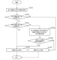
- FIG. 4 is a diagram schematically showing an example of a situation in which a plurality of work vehicles are automatically traveling on roads inside and outside a field; 1 is a flow chart illustrating an example method of route planning and cruise control using a farm road identification system; It is a flowchart which shows the example of the method to identify whether it is a farm road.
- FIG. 4 is a diagram showing a monochrome image corresponding to an example of an image acquired by a camera of a work vehicle;
- FIG. 4 is a diagram showing a monochrome image corresponding to an example of an image acquired by a camera of a work vehicle;
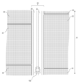
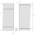
- FIG. 10 is a plan view schematically showing an example of how a work vehicle automatically travels outside a field while using a farm road identification system;
- FIG. 10 is a plan view schematically showing an example of how a work vehicle automatically travels outside a field while using a farm road identification system
- FIG. 10 is a plan view schematically showing an example of how a work vehicle automatically travels outside a field while using a farm road identification system
- It is a flowchart which shows the example of the method to identify whether it is a farm road.
- FIG. 4 is a diagram showing an example of global and local paths generated in an environment with obstacles;
- agricultural machinery means machinery used in agricultural applications.
- Examples of agricultural machinery include tractors, harvesters, rice transplanters, ride-on tenders, vegetable transplanters, lawn mowers, seeders, fertilizer applicators, and agricultural mobile robots.
- a work vehicle such as a tractor function as an "agricultural machine” on its own, but a work vehicle (implement) attached to or towed by the work vehicle and the work vehicle as a whole function as one "agricultural machine”.
- Agricultural machines perform farm work such as plowing, sowing, pest control, fertilization, planting of crops, or harvesting on the ground in fields. These agricultural operations are sometimes referred to as “ground operations” or simply “operations.” Traveling while a vehicle-type agricultural machine performs farm work is sometimes referred to as "working travel.”
- “Automated operation” means that the movement of agricultural machinery is controlled by the operation of the control device, not by manual operation by the driver.
- Agricultural machines that operate automatically are sometimes called “automatic driving farm machines” or “robot farm machines”.
- automated driving farm machines not only the movement of the agricultural machine but also the operation of agricultural work (for example, the operation of the working machine) may be automatically controlled.
- the agricultural machine is a vehicle-type machine
- the automatic driving of the agricultural machine is called “automatic driving”.
- the controller may control at least one of steering, movement speed adjustment, movement start and stop required for movement of the agricultural machine.
- the control device may control operations such as raising and lowering the work implement and starting and stopping the operation of the work implement.
- Movement by automatic operation may include not only movement of the agricultural machine toward a destination along a predetermined route, but also movement following a tracking target.
- An agricultural machine that operates automatically may move partially based on a user's instruction.
- the agricultural machine that automatically operates may operate in a manual operation mode in which the agricultural machine is moved by manual operation by the driver.
- the act of steering an agricultural machine not by manual operation but by the action of a control device is called "automatic steering".
- Part or all of the controller may be external to the agricultural machine.
- Communication, such as control signals, commands, or data, may occur between a control device external to the agricultural machine and the agricultural machine.
- An agricultural machine that operates automatically may move autonomously while sensing the surrounding environment without a human being involved in controlling the movement of the agricultural machine.
- Agricultural machines capable of autonomous movement can run unmanned inside or outside a field (for example, on roads). Obstacle detection and obstacle avoidance operation may be performed during autonomous movement.
- a "work plan” is data that defines a schedule for one or more farm work to be performed by an agricultural machine.
- a work plan may include, for example, information indicating the order of farm work to be performed by the agricultural machine and the field on which each farm work is to be performed.
- the work plan may include information about the days and times each farm work is scheduled to occur.
- a work plan that includes information on the days and times each farm work is scheduled to be performed is specifically referred to as a "work schedule" or simply a "schedule".
- the work schedule may include information on the scheduled start time and/or the scheduled end time of each farm work to be performed on each work day.
- the work plan or work schedule may include information such as the content of work, the implements used, and/or the types and amounts of agricultural materials used for each agricultural work.
- agricultural material means a material used in agricultural work performed by agricultural machinery. Agricultural materials are sometimes simply referred to as “materials.” Agricultural materials may include materials consumed by agricultural operations, such as pesticides, fertilizers, seeds, or seedlings.
- the work plan may be created by a processing device that communicates with the agricultural machine to manage farm work, or a processing device mounted on the agricultural machine. The processing device can, for example, create a work plan based on information input by a user (a farmer, farm worker, etc.) by operating a terminal device.
- a processing device that communicates with agricultural machines and manages farm work is referred to as a “management device”.
- the management device may manage farm work of a plurality of agricultural machines.
- the management device may create a work plan including information on each farm work performed by each of the plurality of agricultural machines.
- the work plan may be downloaded by each agricultural machine and stored in storage. According to the work plan, each agricultural machine can automatically go to the field and perform the scheduled agricultural work.
- Environmental map is data expressing the position or area of an object existing in the environment in which the agricultural machine moves, using a predetermined coordinate system.
- Environmental maps are sometimes simply referred to as "maps" or “map data”.
- the coordinate system that defines the environment map can be, for example, a world coordinate system, such as a geographic coordinate system fixed with respect to the earth.
- the environment map may include information other than position (for example, attribute information and other information) about objects existing in the environment.
- Environmental maps include various types of maps, such as point cloud maps or grid maps. Local map or partial map data generated or processed in the process of constructing an environment map is also referred to as a "map" or "map data”.
- Global path means the data of the route from the starting point to the destination point when the agricultural machine moves automatically, generated by the processing device that performs the route planning. Generating a global path is called global path planning or global path design. In the following description, the global route is also called “target route” or simply “route”.
- a global path may be defined, for example, by coordinate values of points through which the agricultural machine should pass. A point through which the agricultural machine should pass is called a "waypoint", and a line segment connecting adjacent waypoints is called a "link”.
- Local path means a local path capable of avoiding obstacles, which is sequentially generated when the agricultural machine automatically moves along the global path. Generating local paths is called local path planning or local path design.
- a local route is sequentially generated based on data acquired by one or more sensing devices provided on the agricultural machine while the agricultural machine is moving.
- a local route may be defined by multiple waypoints along a portion of the global route. However, if an obstacle exists in the vicinity of the global path, waypoints may be set to bypass the obstacle.
- the length of the links between waypoints in the local path is shorter than the length of the links between waypoints in the global path.
- the device that generates the local route may be the same as or different from the device that generates the global route.
- a management device that manages farm work by an agricultural machine may generate a global route, and a controller mounted on the agricultural machine may generate a local route.
- the combination of the management device and the control device functions as the "processing device" that performs the route planning.
- a farm machine controller may function as a processor that performs both global and local path design.
- “Farm road” means a road that is mainly used for agricultural purposes.
- Agricultural roads are not limited to roads paved with asphalt, but also include unpaved roads covered with soil or gravel.
- Agricultural roads include roads (including private roads) exclusively passable by vehicle-type agricultural machines (for example, work vehicles such as tractors) and roads passable by general vehicles (passenger cars, trucks, buses, etc.). The work vehicle may automatically travel on general roads in addition to farm roads.
- General roads are roads maintained for general vehicle traffic.
- FIG. 1 is a diagram for explaining an overview of an agricultural management system according to an exemplary embodiment of the present disclosure.
- the agricultural management system shown in FIG. 1 includes a work vehicle 100 , a terminal device 400 and a management device 600 .
- Terminal device 400 is a computer used by a user who remotely monitors work vehicle 100 .
- the management device 600 is a computer managed by a business operator who operates an agricultural management system.
- Work vehicle 100 , terminal device 400 , and management device 600 can communicate with each other via network 80 .
- a farm management system may include multiple work vehicles or other agricultural machinery.
- the work vehicle 100 in this embodiment is a tractor.
- Work vehicle 100 can be equipped with implements on one or both of the rear and front portions.
- the work vehicle 100 can travel in a field while performing farm work according to the type of implement.
- the work vehicle 100 may travel inside or outside the field without the implements attached.
- the work vehicle 100 has an automatic driving function.
- the work vehicle 100 can be driven not by manual operation but by the function of the control device.
- the control device in this embodiment is provided inside the work vehicle 100 and can control both the speed and steering of the work vehicle 100 .
- the work vehicle 100 can automatically travel not only inside the farm field but also outside the farm field (for example, roads).
- the work vehicle 100 is equipped with devices such as a GNSS receiver and a LiDAR sensor, which are used for positioning or self-position estimation.
- the control device of work vehicle 100 automatically causes work vehicle 100 to travel based on the position of work vehicle 100 and information on the target route.
- the control device controls the operation of the implements in addition to the travel control of the work vehicle 100 .
- the work vehicle 100 can perform farm work using implements while automatically traveling in the field.
- the work vehicle 100 can automatically travel along the target route on a road outside the field (for example, a farm road or a general road).
- the work vehicle 100 When the work vehicle 100 automatically travels along a road outside a field, the work vehicle 100 follows a target route along a local route capable of avoiding obstacles based on data output from a sensing device such as a camera or a LiDAR sensor. Run while generating. The work vehicle 100 can also detect farm roads based on the data output from the sensing device, and travel while generating a local route on the farm roads. As a result, even if the global route is not correctly set on the farm road, it is possible to appropriately automatically travel on the farm road. Work vehicle 100 may travel in a field while generating a local route in the same manner as described above, or may travel along a target route without generating a local route and an obstacle is detected. You may perform the operation
- a sensing device such as a camera or a LiDAR sensor
- the management device 600 is a computer that manages farm work by the work vehicle 100 .
- the management device 600 may be a server computer that centrally manages information about agricultural fields on the cloud and supports agriculture by utilizing data on the cloud, for example.
- the management device 600 for example, creates a work plan for the work vehicle 100 and performs global route planning for the work vehicle 100 according to the work plan.
- the management device 600 generates a global route (target route) using different methods inside and outside the field.
- the management device 600 generates a target route in the field based on information about the field.
- the management device 600 can store the pre-registered outline of the field, the area of the field, the position of the entrance/exit of the field, the width of the work vehicle 100, the width of the implement, the content of the work, the type of crops to be cultivated, and the growth of the crops.
- a target path in a field can be generated based on a variety of information, such as area, crop growth, or crop row or furrow spacing.
- Management device 600 generates a target course in a field based on information which a user inputted using terminal device 400 or other devices, for example.
- the management device 600 generates a route in the field so as to cover the entire work area where work is performed, for example.
- the management device 600 generates a target route outside the field according to the work plan or the instruction of the user.
- the management device 600 can determine the order of farm work indicated by the work plan, the position of the farm field where each farm work is performed, the position of the entrance/exit of the farm field, the scheduled start and end times of each farm work, road surface conditions, weather conditions, or traffic conditions.
- a target route outside the farm field can be generated based on various information such as.
- the management device 600 may generate a target route based on information indicating a route or waypoints designated by the user by operating the terminal device 400, regardless of the work plan.
- Management device 600 may further generate and edit an environment map based on data collected by work vehicle 100 or other moving objects using sensing devices such as LiDAR sensors.
- Management device 600 transmits the generated work plan, target route, and environment map data to work vehicle 100 . Work vehicle 100 automatically performs movement and farm work based on those data.
- the global route design and the generation (or editing) of the environment map are not limited to the management device 600, and may be performed by another device.
- the control device of work vehicle 100 may perform global route design or environment map generation or editing.
- the terminal device 400 is a computer used by a user who is remote from the work vehicle 100 .
- the terminal device 400 shown in FIG. 1 is a laptop computer, but is not limited to this.
- the terminal device 400 may be a stationary computer such as a desktop PC (personal computer), or a mobile terminal such as a smart phone or tablet computer.
- the terminal device 400 can be used to remotely monitor the work vehicle 100 or remotely operate the work vehicle 100 .
- the terminal device 400 can display images captured by one or more cameras (imaging devices) included in the work vehicle 100 on the display. The user can view the image, check the surroundings of work vehicle 100, and send an instruction to stop or start work vehicle 100.
- the terminal device 400 can also display on the display a setting screen for the user to input information necessary for creating a work plan (for example, a schedule for each agricultural work) for the work vehicle 100 .
- a work plan for example, a schedule for each agricultural work
- the terminal device 400 transmits the input information to the management device 600 .
- Management device 600 creates a work plan based on the information.
- the terminal device 400 may further have a function of displaying on the display a setting screen for the user to input information necessary for setting the target route.
- FIG. 2 is a side view schematically showing an example of work vehicle 100 and implement 300 coupled to work vehicle 100.
- the work vehicle 100 in this embodiment can operate in both manual operation mode and automatic operation mode. In the automatic operation mode, work vehicle 100 can run unmanned. The work vehicle 100 can be automatically driven both inside and outside the field.
- the work vehicle 100 includes a vehicle body 101 , a prime mover (engine) 102 and a transmission (transmission) 103 .
- a vehicle body 101 is provided with wheels 104 with tires and a cabin 105 .
- Wheels 104 include a pair of front wheels 104F and a pair of rear wheels 104R.
- a driver's seat 107 , a steering device 106 , an operation terminal 200 , and a group of switches for operation are provided inside the cabin 105 .
- the work vehicle 100 travels in a field, one or both of the front wheels 104F and the rear wheels 104R are replaced with (a plurality of) wheels (crawlers) equipped with tracks instead of wheels with tires. good too.
- the work vehicle 100 includes a plurality of sensing devices that sense the surroundings of the work vehicle 100.
- the sensing device includes multiple cameras 120 , LiDAR sensors 140 and multiple obstacle sensors 130 .
- the cameras 120 may be provided on the front, rear, left, and right of the work vehicle 100, for example. Camera 120 photographs the environment around work vehicle 100 and generates image data. Images acquired by the camera 120 can be transmitted to the terminal device 400 for remote monitoring. The image may be used to monitor work vehicle 100 during unmanned operation. The camera 120 can also be used to generate images for recognizing surrounding features or obstacles, white lines, signs, displays, etc. when the work vehicle 100 travels on a road outside the field (farm road or general road). can be used.
- the LiDAR sensor 140 in the example of FIG. 2 is arranged at the lower front portion of the vehicle body 101. LiDAR sensor 140 may be provided at other locations.
- the LiDAR sensor 140 detects the distance and direction to each measurement point of an object present in the surrounding environment, or two-dimensional or three-dimensional coordinate values of each measurement point, while the work vehicle 100 is mainly traveling outside the farm field. Repeatedly outputs sensor data indicating The sensor data output from LiDAR sensor 140 is processed by the control device of work vehicle 100 .
- the control device can estimate the self-location of the work vehicle 100 by matching the sensor data and the environment map.
- the control device further detects objects such as obstacles existing around work vehicle 100 based on the sensor data, and generates a local route along which work vehicle 100 should actually travel along the global route. be able to.
- the controller can also generate or edit an environment map using algorithms such as SLAM (Simultaneous Localization and Mapping).
- Work vehicle 100 may include multiple LiDAR sensors arranged at different locations and with
- a plurality of obstacle sensors 130 shown in FIG. 2 are provided at the front and rear of the cabin 105. Obstacle sensors 130 may be placed at other locations as well. For example, one or more obstacle sensors 130 may be provided at any position on the side, front, and rear of the vehicle body 101 . Obstacle sensors 130 may include, for example, laser scanners or ultrasonic sonars. The obstacle sensor 130 is used to detect surrounding obstacles and stop or detour the work vehicle 100 during automatic travel.
- a LiDAR sensor 140 may be utilized as one of the obstacle sensors 130 .
- the work vehicle 100 further includes a GNSS unit 110.
- GNSS unit 110 includes a GNSS receiver.
- the GNSS receiver may include an antenna that receives signals from GNSS satellites and a processor that calculates the position of work vehicle 100 based on the signals received by the antenna.
- the GNSS unit 110 receives satellite signals transmitted from multiple GNSS satellites and performs positioning based on the satellite signals.
- GNSS is a general term for satellite positioning systems such as GPS (Global Positioning System), QZSS (Quasi-Zenith Satellite System, eg, Michibiki), GLONASS, Galileo, and BeiDou.
- GPS Global Positioning System
- QZSS Quadasi-Zenith Satellite System
- GLONASS Galileo
- BeiDou BeiDou.
- the GNSS unit 110 may include an inertial measurement unit (IMU). Signals from the IMU can be used to supplement the location data.
- the IMU can measure the tilt and minute movements of work vehicle 100 . Positioning performance can be improved by using data obtained by the IMU to supplement position data based on satellite signals.
- the control device of the work vehicle 100 may use sensing data acquired by a sensing device such as the camera 120 or the LiDAR sensor 140 for positioning in addition to the positioning results obtained by the GNSS unit 110 .
- a sensing device such as the camera 120 or the LiDAR sensor 140
- the control device of the work vehicle 100 may use sensing data acquired by a sensing device such as the camera 120 or the LiDAR sensor 140 for positioning in addition to the positioning results obtained by the GNSS unit 110 .
- a sensing device such as the camera 120 or the LiDAR sensor 140 for positioning in addition to the positioning results obtained by the GNSS unit 110 .
- a feature functioning as a feature point in the environment in which the work vehicle 100 travels such as a farm road, a forest road, a general road, or an orchard
- data acquired by the camera 120 or the LiDAR sensor 140 and pre-stored Based on the environment map stored in the device, the position and orientation of work vehicle 100 can be estimated with high accuracy.
- the prime mover 102 may be, for example, a diesel engine.
- An electric motor may be used instead of the diesel engine.
- the transmission 103 can change the propulsive force and the moving speed of the work vehicle 100 by shifting.
- the transmission 103 can also switch between forward and reverse travel of the work vehicle 100 .
- the steering device 106 includes a steering wheel, a steering shaft connected to the steering wheel, and a power steering device that assists steering by the steering wheel.
- the front wheels 104F are steerable wheels, and the running direction of the work vehicle 100 can be changed by changing the turning angle (also referred to as the "steering angle") of the front wheels 104F.
- the steering angle of the front wheels 104F can be changed by operating the steering wheel.
- the power steering system includes a hydraulic system or an electric motor that supplies an assist force for changing the steering angle of the front wheels 104F. When automatic steering is performed, the steering angle is automatically adjusted by the power of the hydraulic system or the electric motor under the control of the control device arranged in the work vehicle 100 .
- a coupling device 108 is provided at the rear portion of the vehicle body 101 .
- the coupling device 108 includes, for example, a three-point support device (also called a "three-point link” or “three-point hitch"), a PTO (Power Take Off) shaft, a universal joint, and a communication cable.
- the implement 300 can be attached to and detached from the work vehicle 100 by the coupling device 108 .
- the coupling device 108 can change the position or posture of the implement 300 by elevating the three-point link by, for example, a hydraulic device.
- power can be sent from the work vehicle 100 to the implement 300 via the universal joint.
- the work vehicle 100 can cause the implement 300 to perform a predetermined work while pulling the implement 300 .
- the connecting device may be provided in front of the vehicle body 101 . In that case, implements can be connected to the front of work vehicle 100 .
- the implement 300 shown in FIG. 2 is a rotary tiller, but the implement 300 is not limited to the rotary tiller. Any implement such as seeder, spreader, transplanter, mower, rake, baler, harvester, sprayer, or harrow. It can be used by connecting to the work vehicle 100 .
- the work vehicle 100 shown in FIG. 2 is capable of manned operation, but may only be compatible with unmanned operation. In that case, components required only for manned operation, such as cabin 105 , steering device 106 and driver's seat 107 , may not be provided in work vehicle 100 .
- the unmanned work vehicle 100 can travel autonomously or remotely controlled by a user.
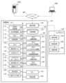
- FIG. 3 is a block diagram showing a configuration example of the work vehicle 100 and the implement 300. As shown in FIG. Work vehicle 100 and implement 300 may communicate with each other via a communication cable included in coupling device 108 . Work vehicle 100 can communicate with terminal device 400 and management device 600 via network 80 .
- the GNSS unit 110 comprises a GNSS receiver 111 , an RTK receiver 112 , an inertial measurement unit (IMU) 115 and processing circuitry 116 .
- the sensor group 150 includes a steering wheel sensor 152 , a steering angle sensor 154 and an axle sensor 156 .
- Control system 160 includes storage device 170 and control device 180 .
- the controller 180 comprises a plurality of electronic control units (ECUs) 181-186.
- the implement 300 includes a drive device 340 , a control device 380 and a communication device 390 . Note that FIG. 3 shows constituent elements that are relatively highly relevant to the operation of automatic driving by the work vehicle 100, and illustration of other constituent elements is omitted.
- the GNSS receiver 111 in the GNSS unit 110 receives satellite signals transmitted from multiple GNSS satellites and generates GNSS data based on the satellite signals.
- GNSS data is generated in a predetermined format, eg, NMEA-0183 format.
- GNSS data may include, for example, values indicating the identification number, elevation, azimuth, and received strength of each satellite from which the satellite signal was received.
- the GNSS unit 110 shown in FIG. 3 performs positioning of the work vehicle 100 using RTK (Real Time Kinematic)-GNSS.
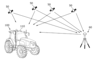
- FIG. 4 is a conceptual diagram showing an example of the work vehicle 100 that performs positioning by RTK-GNSS. Positioning by RTK-GNSS uses correction signals transmitted from the reference station 60 in addition to satellite signals transmitted from a plurality of GNSS satellites 50 .
- the reference station 60 can be installed near the field where the work vehicle 100 travels (for example, within 10 km from the work vehicle 100).
- the reference station 60 generates a correction signal, for example in RTCM format, based on the satellite signals received from the plurality of GNSS satellites 50 and transmits it to the GNSS unit 110 .
- RTK receiver 112 includes an antenna and modem to receive correction signals transmitted from reference station 60 .
- the processing circuit 116 of the GNSS unit 110 corrects the positioning result by the GNSS receiver 111 based on the correction signal.
- RTK-GNSS it is possible to perform positioning with an accuracy of, for example, an error of several centimeters.
- Location information including latitude, longitude and altitude information, is obtained through RTK-GNSS high-precision positioning.
- the GNSS unit 110 calculates the position of the work vehicle 100, for example, at a frequency of about 1 to 10 times per second.
- the positioning method is not limited to RTK-GNSS, and any positioning method (interferometric positioning method, relative positioning method, etc.) that can obtain position information with the required accuracy can be used.
- positioning may be performed using VRS (Virtual Reference Station) or DGPS (Differential Global Positioning System). If position information with required accuracy can be obtained without using the correction signal transmitted from the reference station 60, the position information may be generated without using the correction signal.
- GNSS unit 110 may not include RTK receiver 112 .
- the position of work vehicle 100 is estimated.
- the position of work vehicle 100 may be estimated by matching data output from LiDAR sensor 140 and/or camera 120 with a highly accurate environmental map.
- the GNSS unit 110 in this embodiment further includes an IMU 115 .
- IMU 115 may include a 3-axis accelerometer and a 3-axis gyroscope.
- the IMU 115 may include an orientation sensor, such as a 3-axis geomagnetic sensor.
- IMU 115 functions as a motion sensor and can output signals indicating various quantities such as acceleration, speed, displacement, and attitude of work vehicle 100 .
- Processing circuitry 116 may more accurately estimate the position and orientation of work vehicle 100 based on signals output from IMU 115 in addition to satellite signals and correction signals. Signals output from IMU 115 may be used to correct or impute positions calculated based on satellite signals and correction signals.
- IMU 115 outputs signals more frequently than GNSS receiver 111 .
- processing circuitry 116 can measure the position and orientation of work vehicle 100 at a higher frequency (eg, 10 Hz or higher).
- a higher frequency eg, 10 Hz or higher.
- IMU 115 may be provided as a separate device from GNSS unit 110 .
- the camera 120 is an imaging device that captures the environment around the work vehicle 100 .
- the camera 120 includes an image sensor such as a CCD (Charge Coupled Device) or CMOS (Complementary Metal Oxide Semiconductor).
- Camera 120 may also include an optical system, including one or more lenses, and signal processing circuitry.
- the camera 120 captures an image of the environment around the work vehicle 100 while the work vehicle 100 is traveling, and generates image (for example, moving image) data.
- the camera 120 can capture moving images at a frame rate of 3 frames per second (fps) or higher, for example.
- the image generated by the camera 120 can be used, for example, when a remote monitor uses the terminal device 400 to check the environment around the work vehicle 100 .
- the images generated by camera 120 may be used for positioning or obstacle detection.
- a plurality of cameras 120 may be provided at different positions on work vehicle 100, or a single camera may be provided. There may be separate visible cameras for generating visible light images and infrared cameras for generating infrared images. Both visible and infrared cameras may be provided as cameras for generating images for surveillance. Infrared cameras can also be used to detect obstacles at night.
- the obstacle sensor 130 detects objects existing around the work vehicle 100 .
- Obstacle sensors 130 may include, for example, laser scanners or ultrasonic sonars. Obstacle sensor 130 outputs a signal indicating the presence of an obstacle when an object is present closer than a predetermined distance from obstacle sensor 130 .
- a plurality of obstacle sensors 130 may be provided at different positions on work vehicle 100 . For example, multiple laser scanners and multiple ultrasonic sonars may be placed at different locations on work vehicle 100 . By providing such many obstacle sensors 130, blind spots in monitoring obstacles around the work vehicle 100 can be reduced.
- the steering wheel sensor 152 measures the rotation angle of the steering wheel of the work vehicle 100.
- the steering angle sensor 154 measures the steering angle of the front wheels 104F, which are steered wheels. Measured values by the steering wheel sensor 152 and the steering angle sensor 154 are used for steering control by the controller 180 .
- the axle sensor 156 measures the rotational speed of the axle connected to the wheel 104, that is, the number of revolutions per unit time.
- Axle sensor 156 can be, for example, a sensor utilizing a magnetoresistive element (MR), a Hall element, or an electromagnetic pickup.
- the axle sensor 156 outputs, for example, a numerical value indicating the number of rotations per minute (unit: rpm) of the axle.
- Axle sensors 156 are used to measure the speed of work vehicle 100 .
- the drive device 240 includes various devices necessary for running the work vehicle 100 and driving the implements 300, such as the prime mover 102, the transmission device 103, the steering device 106, and the coupling device 108 described above.
- Prime mover 102 may comprise an internal combustion engine, such as a diesel engine, for example.
- Drive system 240 may include an electric motor for traction instead of or in addition to the internal combustion engine.
- the buzzer 220 is an audio output device that emits a warning sound to notify an abnormality. Buzzer 220 emits a warning sound when an obstacle is detected, for example, during automatic driving. Buzzer 220 is controlled by controller 180 .
- the storage device 170 includes one or more storage media such as flash memory or magnetic disk.
- Storage device 170 stores various data generated by GNSS unit 110 , camera 120 , obstacle sensor 130 , LiDAR sensor 140 , sensor group 150 , and control device 180 .
- the data stored in storage device 170 may include map data (environmental map) of the environment in which work vehicle 100 travels and data of a global route (target route) for automatic driving.
- the environment map includes information of a plurality of farm fields where work vehicle 100 performs farm work and roads around the fields.
- the environment map and target route may be generated by a processor in management device 600 .
- the control device 180 in this embodiment has a function of generating or editing an environment map and a target route.
- Control device 180 can edit the environment map and target route acquired from management device 600 according to the traveling environment of work vehicle 100 .
- the storage device 170 also stores work plan data received by the communication device 190 from the management device 600 .
- a work plan includes information about a plurality of farm tasks that work vehicle 100 will perform over a plurality of work days.
- the work plan may be, for example, work schedule data including information on the scheduled time of each farm work to be performed by the work vehicle 100 on each work day.
- the storage device 170 also stores a computer program that causes each ECU in the control device 180 to execute various operations described later.
- Such a computer program can be provided to work vehicle 100 via a storage medium (such as a semiconductor memory or an optical disk) or an electric communication line (such as the Internet).
- Such computer programs may be sold as commercial software.
- the control device 180 includes multiple ECUs.
- the plurality of ECUs include, for example, an ECU 181 for speed control, an ECU 182 for steering control, an ECU 183 for implement control, an ECU 184 for automatic driving control, an ECU 185 for route generation, and an ECU 186 for map generation.
- the ECU 181 controls the speed of the work vehicle 100 by controlling the prime mover 102, the transmission 103, and the brakes included in the drive device 240.
- the ECU 182 controls the steering of the work vehicle 100 by controlling the hydraulic system or the electric motor included in the steering system 106 based on the measurement value of the steering wheel sensor 152 .
- the ECU 183 controls the operations of the three-point link and the PTO shaft included in the coupling device 108 in order to cause the implement 300 to perform desired operations. ECU 183 also generates signals that control the operation of implement 300 and transmits the signals from communication device 190 to implement 300 .
- the ECU 184 performs calculations and controls for realizing automatic driving based on data output from the GNSS unit 110, the camera 120, the obstacle sensor 130, the LiDAR sensor 140, and the sensor group 150. For example, ECU 184 identifies the position of work vehicle 100 based on data output from at least one of GNSS unit 110 , camera 120 , and LiDAR sensor 140 . Within the field, ECU 184 may determine the position of work vehicle 100 based solely on data output from GNSS unit 110 . ECU 184 may estimate or correct the position of work vehicle 100 based on data acquired by camera 120 or LiDAR sensor 140 . By using the data acquired by the camera 120 or the LiDAR sensor 140, the accuracy of positioning can be further improved.
- ECU 184 estimates the position of work vehicle 100 using data output from LiDAR sensor 140 or camera 120 .
- the ECU 184 may estimate the position of the work vehicle 100 by matching data output from the LiDAR sensor 140 or the camera 120 with an environmental map.
- ECU 184 performs calculations necessary for work vehicle 100 to travel along the target route or local route based on the estimated position of work vehicle 100 .
- the ECU 184 sends a speed change command to the ECU 181 and a steering angle change command to the ECU 182 .
- ECU 181 changes the speed of work vehicle 100 by controlling prime mover 102, transmission 103, or brakes in response to speed change commands.
- the ECU 182 changes the steering angle by controlling the steering device 106 in response to the command to change the steering angle.
- the ECU 185 sequentially generates local routes that can avoid obstacles while the work vehicle 100 is traveling along the target route. For example, the ECU 185 recognizes farm roads and obstacles existing around the work vehicle 100 based on data output from the camera 120 , the obstacle sensor 130 , and the LiDAR sensor 140 while the work vehicle 100 is traveling. The ECU 185 generates a local route on the farm road to avoid the recognized obstacles.
- the ECU 185 may have a function of global route design instead of the management device 600 . In that case, the ECU 185 determines the destination of the work vehicle 100 based on the work plan stored in the storage device 170, and determines the target route from the start point of movement of the work vehicle 100 to the destination point. Based on the environmental map containing the road information stored in the storage device 170, the ECU 185 can create, for example, a route that can reach the destination in the shortest time as a target route.
- the ECU 186 creates or edits a map of the environment in which the work vehicle 100 travels.
- an environment map generated by an external device such as management device 600 is transmitted to work vehicle 100 and recorded in storage device 170, but ECU 186 can instead generate or edit the environment map. .
- An environment map may be generated based on sensor data output from the LiDAR sensor 140 .
- the ECU 186 sequentially generates three-dimensional point cloud data based on sensor data output from the LiDAR sensor 140 while the work vehicle 100 is running.
- the ECU 186 can generate an environment map by connecting the sequentially generated point cloud data using an algorithm such as SLAM, for example.
- the environment map generated in this manner is a highly accurate three-dimensional map and can be used by the ECU 184 for self-position estimation. Based on this 3D map, a 2D map can be generated for use in global route planning.
- the three-dimensional map used for self-localization and the two-dimensional map used for global route planning are both referred to as "environmental maps.”
- the ECU 186 further adds various attribute information related to structures, road conditions, road passability, etc. recognized based on the data output from the camera 120 or the LiDAR sensor 140 to the map. can also be edited.
- control device 180 realizes automatic operation.
- control device 180 controls drive device 240 based on the measured or estimated position of work vehicle 100 and the target route. Thereby, the control device 180 can cause the work vehicle 100 to travel along the target route.
- a plurality of ECUs included in the control device 180 can communicate with each other according to a vehicle bus standard such as CAN (Controller Area Network). Instead of CAN, a higher-speed communication method such as in-vehicle Ethernet (registered trademark) may be used.
- CAN Controller Area Network
- a higher-speed communication method such as in-vehicle Ethernet (registered trademark) may be used.
- An on-board computer that integrates at least some functions of the ECUs 181 to 186 may be provided.
- the control device 180 may include ECUs other than the ECUs 181 to 186, and an arbitrary number of ECUs may be provided according to functions.
- Each ECU includes processing circuitry that includes one or more processors.
- the communication device 190 is a device including circuits for communicating with the implement 300 , the terminal device 400 and the management device 600 .
- Communication device 190 includes circuitry for transmitting and receiving signals conforming to the ISOBUS standard, such as ISOBUS-TIM, to and from communication device 390 of implement 300 .
- the implement 300 can be caused to perform a desired operation, or information can be obtained from the implement 300 .
- Communication device 190 may further include an antenna and communication circuitry for transmitting and receiving signals over network 80 to and from respective communication devices of terminal device 400 and management device 600 .
- Network 80 may include, for example, cellular mobile communication networks such as 3G, 4G or 5G and the Internet.
- the communication device 190 may have a function of communicating with a mobile terminal used by a supervisor near the work vehicle 100 .
- Communication with such mobile terminals is based on any wireless communication standard, such as Wi-Fi (registered trademark), cellular mobile communication such as 3G, 4G or 5G, or Bluetooth (registered trademark).
- Wi-Fi registered trademark
- cellular mobile communication such as 3G, 4G or 5G
- Bluetooth registered trademark
- the operation terminal 200 is a terminal for the user to execute operations related to the running of the work vehicle 100 and the operation of the implement 300, and is also called a virtual terminal (VT).
- Operation terminal 200 may include a display device such as a touch screen and/or one or more buttons.
- the display device can be a display such as a liquid crystal or an organic light emitting diode (OLED), for example.
- OLED organic light emitting diode
- the operation terminal 200 the user can perform various operations such as switching the automatic driving mode on/off, recording or editing an environment map, setting a target route, and switching the implement 300 on/off. can be executed. At least part of these operations can also be realized by operating the operation switch group 210 .
- Operation terminal 200 may be configured to be removable from work vehicle 100 .
- a user located away from work vehicle 100 may operate operation terminal 200 that has been removed to control the operation of work vehicle 100 .
- the user may control the operation of work vehicle 100 by operating a computer, such as terminal device 400 , in which necessary application software is installed, instead of operating terminal 200 .
- FIG. 5 is a diagram showing an example of the operation terminal 200 and the operation switch group 210 provided inside the cabin 105.
- FIG. Inside the cabin 105, an operation switch group 210 including a plurality of switches that can be operated by the user is arranged.
- the operation switch group 210 includes, for example, a switch for selecting the gear stage of the main transmission or the sub-transmission, a switch for switching between the automatic driving mode and the manual driving mode, a switch for switching between forward and reverse, and an implement.
- a switch or the like for raising or lowering 300 may be included. Note that if the work vehicle 100 only operates unmanned and does not have a function of manned operation, the work vehicle 100 need not include the operation switch group 210 .
- the driving device 340 in the implement 300 shown in FIG. 3 performs operations necessary for the implement 300 to perform a predetermined work.
- Drive device 340 includes a device, such as a hydraulic device, an electric motor, or a pump, depending on the application of implement 300 .
- Controller 380 controls the operation of drive 340 .
- Control device 380 causes drive device 340 to perform various operations in response to signals transmitted from work vehicle 100 via communication device 390 .
- a signal corresponding to the state of the implement 300 can also be transmitted from the communication device 390 to the work vehicle 100 .
- FIG. 6 is a block diagram illustrating a schematic hardware configuration of the management device 600 and the terminal device 400. As shown in FIG. 6
- the management device 600 includes a storage device 650 , a processor 660 , a ROM (Read Only Memory) 670 , a RAM (Random Access Memory) 680 and a communication device 690 . These components are communicatively connected to each other via a bus.
- the management device 600 can function as a cloud server that manages the schedule of agricultural work in the field performed by the work vehicle 100 and utilizes managed data to support agriculture.
- the user can use the terminal device 400 to input information necessary for creating a work plan and upload the information to the management device 600 via the network 80 . Based on the information, the management device 600 can create a farm work schedule, that is, a work plan.
- Management device 600 is also capable of generating or editing environmental maps and global route planning for work vehicle 100 .
- the environment map may be distributed from a computer outside the management device 600 .
- the communication device 690 is a communication module for communicating with the work vehicle 100 and the terminal device 400 via the network 80.
- the communication device 690 can perform wired communication conforming to a communication standard such as IEEE1394 (registered trademark) or Ethernet (registered trademark), for example.
- the communication device 690 may perform wireless communication conforming to the Bluetooth® standard or Wi-Fi standard, or cellular mobile communication such as 3G, 4G or 5G.
- the processor 660 may be, for example, a semiconductor integrated circuit including a central processing unit (CPU).
- Processor 660 may be implemented by a microprocessor or microcontroller.
- the processor 660 is an FPGA (Field Programmable Gate Array) equipped with a CPU, a GPU (Graphics Processing Unit), an ASIC (Application Specific Integrated Circuit), an ASSP (Application Specific Standard Product), or selected from these circuits. It can also be realized by a combination of two or more circuits.
- the processor 660 sequentially executes a computer program describing a group of instructions for executing at least one process stored in the ROM 670 to achieve desired processes.
- the ROM 670 is, for example, a writable memory (eg PROM), a rewritable memory (eg flash memory), or a read-only memory.
- ROM 670 stores programs that control the operation of processor 660 .
- the ROM 670 does not have to be a single storage medium, and may be a collection of multiple storage media. Part of the collection of multiple storage media may be removable memory.
- the RAM 680 provides a work area for temporarily expanding the control program stored in the ROM 670 at boot time.
- the RAM 680 does not have to be a single storage medium, and may be a collection of multiple storage media.
- the storage device 650 mainly functions as database storage.
- Storage device 650 may be, for example, a magnetic storage device or a semiconductor storage device.
- An example of a magnetic storage device is a hard disk drive (HDD).
- An example of a semiconductor memory device is a solid state drive (SSD).
- Storage device 650 may be a device independent of management device 600 .
- the storage device 650 may be a storage device connected to the management device 600 via the network 80, such as a cloud storage.
- the terminal device 400 includes an input device 420 , a display device 430 , a storage device 450 , a processor 460 , a ROM 470 , a RAM 480 and a communication device 490 . These components are communicatively connected to each other via a bus.
- the input device 420 is a device for converting a user's instruction into data and inputting it to the computer.
- Input device 420 may be, for example, a keyboard, mouse, or touch panel.
- Display device 430 may be, for example, a liquid crystal display or an organic EL display. Descriptions of the processor 460, the ROM 470, the RAM 480, the storage device 450, and the communication device 490 are the same as those described in the hardware configuration example of the management device 600, and the description thereof will be omitted.
- the work vehicle 100 in this embodiment can automatically travel both inside and outside the field.
- the work vehicle 100 drives the implement 300 to perform predetermined farm work while traveling along a preset target route.
- the work vehicle 100 stops traveling, emits a warning sound from the buzzer 220, and transmits a warning signal to the terminal device 400.
- Positioning of the work vehicle 100 in the field is performed mainly based on data output from the GNSS unit 110 .
- the work vehicle 100 automatically travels along a target route set on a farm road or a general road outside the field.
- the work vehicle 100 travels while performing local route design based on data acquired by the camera 120 or the LiDAR sensor 140 while traveling outside the field.
- the work vehicle 100 can detect a farm road based on data acquired by the camera 120 or the LiDAR sensor 140 while traveling outside a field, and can travel while generating a local route on the farm road.
- work vehicle 100 avoids the obstacle or stops on the spot.
- the position of work vehicle 100 is estimated based on data output from LiDAR sensor 140 or camera 120 in addition to positioning data output from GNSS unit 110 .
- FIG. 7 is a diagram schematically showing an example of the working vehicle 100 that automatically travels along a target route in a field.
- the farm field includes a work area 72 where work vehicle 100 performs work using implement 300, and a headland 74 located near the outer periphery of the farm field. Which area of the field on the map corresponds to the work area 72 or the headland 74 can be set in advance by the user.
- the target paths in this example include a plurality of parallel main paths P1 and a plurality of turning paths P2 connecting the plurality of main paths P1.
- the main path P1 is located within the working area 72 and the turning path P2 is located within the headland 74 .
- each main path P1 may include a curved portion.
- the dashed line in FIG. 7 represents the working width of implement 300 .
- the working width is preset and recorded in the storage device 170 .
- the working width can be set and recorded by the user operating the operation terminal 200 or the terminal device 400 . Alternatively, the working width may be automatically recognized and recorded when implement 300 is connected to work vehicle 100 .
- the intervals between the main paths P1 can be set according to the working width.
- a target route can be created based on a user's operation before automatic driving is started.
- the target route can be created, for example, so as to cover the entire work area 72 in the field.
- the work vehicle 100 automatically travels along a target route as shown in FIG. 7 from a work start point to a work end point while repeating reciprocation. Note that the target route shown in FIG. 7 is merely an example, and the method of determining the target route is arbitrary.
- control device 180 Next, an example of control during automatic operation in a field by the control device 180 will be described.
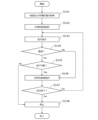
- FIG. 8 is a flowchart showing an example of the steering control operation during automatic driving executed by the control device 180.
- the control device 180 performs automatic steering by executing the operations of steps S121 to S125 shown in FIG. As for the speed, it is maintained at a preset speed, for example.
- the control device 180 acquires data indicating the position of the work vehicle 100 generated by the GNSS unit 110 while the work vehicle 100 is traveling (step S121).
- control device 180 calculates the deviation between the position of work vehicle 100 and the target route (step S122). The deviation represents the distance between the position of work vehicle 100 at that time and the target route.
- the control device 180 determines whether or not the calculated positional deviation exceeds a preset threshold value (step S123).
- control device 180 changes the steering angle by changing the control parameters of the steering device included in the drive device 240 so that the deviation becomes smaller. If the deviation does not exceed the threshold in step S123, the operation of step S124 is omitted. In subsequent step S125, control device 180 determines whether or not an operation end command has been received.
- An operation end command can be issued, for example, when the user instructs to stop the automatic operation by remote control, or when work vehicle 100 reaches the destination. If the command to end the operation has not been issued, the process returns to step S121, and similar operations are executed based on the newly measured position of the work vehicle 100.
- FIG. The control device 180 repeats the operations of steps S121 to S125 until an operation end command is issued. The above operations are executed by ECUs 182 and 184 in control device 180 .
- controller 180 controls drive 240 based only on the deviation between the position of work vehicle 100 identified by GNSS unit 110 and the target path, but also takes into account heading deviation. may be controlled. For example, when the azimuth deviation, which is the angular difference between the direction of the work vehicle 100 identified by the GNSS unit 110 and the direction of the target route, exceeds a preset threshold value, the control device 180 drives according to the deviation.
- a control parameter eg, steering angle
- FIG. 9A is a diagram showing an example of the work vehicle 100 traveling along the target route P.
- FIG. 9B is a diagram showing an example of work vehicle 100 at a position shifted to the right from target path P.
- FIG. 9C is a diagram showing an example of work vehicle 100 at a position shifted to the left from target path P.
- FIG. 9D is a diagram showing an example of the work vehicle 100 oriented in a direction inclined with respect to the target path P.
- the pose indicating the position and orientation of work vehicle 100 measured by GNSS unit 110 is expressed as r(x, y, ⁇ ).
- (x, y) are coordinates representing the position of the reference point of work vehicle 100 in the XY coordinate system, which is a two-dimensional coordinate system fixed to the earth.
- the reference point of work vehicle 100 is at the position where the GNSS antenna is installed on the cabin, but the position of the reference point is arbitrary.
- ⁇ is an angle representing the measured orientation of work vehicle 100 .
- the target path P is parallel to the Y-axis, but in general the target path P is not necessarily parallel to the Y-axis.
- control device 180 maintains the steering angle and speed of work vehicle 100 without changing.
- control device 180 steers work vehicle 100 so that the traveling direction of work vehicle 100 leans leftward and approaches path P. change the angle.
- the speed may be changed in addition to the steering angle.
- the magnitude of the steering angle can be adjusted, for example, according to the magnitude of the positional deviation ⁇ x.
- control device 180 steers so that the traveling direction of work vehicle 100 leans to the right and approaches path P. change the angle. Also in this case, the speed may be changed in addition to the steering angle. The amount of change in the steering angle can be adjusted, for example, according to the magnitude of the positional deviation ⁇ x.
- control device 180 when work vehicle 100 does not deviate greatly from target path P but is oriented in a different direction from target path P, control device 180 performs steering such that azimuth deviation ⁇ becomes small. change the angle. Also in this case, the speed may be changed in addition to the steering angle.
- the magnitude of the steering angle can be adjusted, for example, according to the respective magnitudes of the position deviation ⁇ x and heading deviation ⁇ . For example, the smaller the absolute value of the positional deviation ⁇ x, the larger the amount of change in the steering angle corresponding to the azimuth deviation ⁇ .
- the absolute value of the positional deviation ⁇ x is large, the steering angle will be greatly changed in order to return to the route P, so the absolute value of the azimuth deviation ⁇ will inevitably become large. Conversely, when the absolute value of the positional deviation ⁇ x is small, it is necessary to make the azimuth deviation ⁇ close to zero. Therefore, it is appropriate to relatively increase the weight (that is, the control gain) of the azimuth deviation ⁇ for determining the steering angle.
- a control technique such as PID control or MPC control (model predictive control) can be applied to the steering control and speed control of work vehicle 100 .
- PID control or MPC control model predictive control
- control device 180 When an obstacle is detected by one or more obstacle sensors 130 during travel, the control device 180 causes the work vehicle 100 to stop. At this time, the buzzer 220 may emit a warning sound or may transmit a warning signal to the terminal device 400 . If obstacle avoidance is possible, controller 180 may control drive 240 to avoid the obstacle.
- the work vehicle 100 in this embodiment can automatically travel not only inside the field but also outside the field.
- the control device 180 detects objects (for example, other vehicles, pedestrians, etc.) that are relatively distant from the work vehicle 100 based on data output from the camera 120 or the LiDAR sensor 140. can do.
- the control device 180 generates a local route to avoid the detected object, and performs speed control and steering control along the local route, thereby realizing automatic driving on the road outside the field.
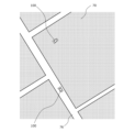
- FIG. 10 is a diagram schematically showing an example of a situation in which a plurality of work vehicles 100 are automatically traveling inside a farm field 70 and on roads 76 outside the farm field 70 .
- the storage device 170 records an environmental map of an area including a plurality of farm fields and roads around them, and a target route.
- Environmental maps and target routes may be generated by management device 600 or ECU 185 .
- work vehicle 100 travels on a road, work vehicle 100 moves along a target route while sensing the surroundings using sensing devices such as camera 120 and LiDAR sensor 140 with implement 300 raised. run.
- the control device 180 sequentially generates local routes and causes the work vehicle 100 to travel along the local routes. As a result, it is possible to automatically travel while avoiding obstacles.
- the target route may be changed according to the situation.
- the sensing device of the work vehicle 100 and the control device 180 of the work vehicle 100 in this embodiment cooperate to function as a farm road identification system for the work vehicle 100 .
- the agricultural road identification system can identify whether the road on which the working vehicle 100 is to travel is a agricultural road.
- the farm road identification system is mainly used while the working vehicle 100 is automatically traveling outside the field.
- a farm road identification system can perform actions to identify whether it is a farm road and generate a local route along the farm road.
- the farm road identification system may identify farm roads while the work vehicle 100 is manually driven outside the field and collect data regarding the location and width of the farm roads. The collected data may be used to generate maps containing detailed information about farm roads.
- the sensing device of the work vehicle 100 includes multiple cameras 120, LiDAR sensors 140, and multiple obstacle sensors 130, for example, in the example of FIG. Without being limited to this, the sensing device of work vehicle 100 may include at least one of camera 120 , obstacle sensor 130 , and LiDAR sensor 140 . At least one sensing device of the work vehicle 100 can be used as a sensing device in the farm road identification system. As the sensing device of the farm road identification system, an example of using the sensing device provided on the work vehicle 100 is described here, but the sensing device is not limited to this example. For example, a sensing device of an agricultural machine other than the work vehicle 100 or a moving object such as a drone (Unmanned Arial Vehicle: UAV) may be used as the sensing device of the farm road identification system.
- UAV Unmanned Arial Vehicle
- the sensing device senses the ground on which the work vehicle 100 travels (for example, the ground located on the traveling direction side of the work vehicle 100) and acquires sensing data related to the ground.
- This sensing data may be referred to as "first sensing data”.
- the sensing device senses the environment around the work vehicle 100 and acquires sensing data related to the surrounding environment including features other than the ground.
- This sensing data may be referred to as "second sensing data”.
- the first sensing data and the second sensing data may be acquired by the same sensing device, or may be acquired by different sensing devices.
- the first sensing data may be acquired by the camera 120 and the second sensing data may be acquired by the LiDAR sensor 140, or vice versa.
- both camera 120 and LiDAR sensor 140 may be used to acquire one or both of the first sensing data and the second sensing data.
- the first sensing data acquired by camera 120 may include image data of the ground on which work vehicle 100 travels.
- the first sensing data acquired by LiDAR sensor 140 may include point cloud data of the ground on which work vehicle 100 travels.
- the second sensing data acquired by sensing by camera 120 may include image data of the environment around work vehicle 100 .
- the second sensing data obtained by sensing by the LiDAR sensor 140 may include point cloud data of the environment around the work vehicle 100 .
- the control device 180 of the work vehicle 100 functions as a processing device that identifies whether the road on which the work vehicle 100 is to travel is a farm road based on the first sensing data and the second sensing data.
- a processing device of the farm road identification system an example in which the control device 180 functions as a processing device of the farm road identification system will be described, but part or all of the processing executed by the control device 180 in the farm road identification system may be executed by another device. good.
- Such other devices may be any of management device 600 (processor 660), terminal device 400 (processor 460) and operation terminal 200.
- FIG. For example, if part of the processing performed by the control device 180 is performed by the processor 660 of the management device 600, the combination of the control device 180 and the management device 600 functions as the processing device of the farm road identification system.
- the route generation ECU 185 of the control device 180 functions as a processing device of the farm road identification system
- the farm road identification processing may be executed by another ECU of the control device 180.
- the control device 180 may further have an ECU for identifying whether it is a farm road.
- the control device 180 acquires information on the transverse profile of the ground on which the work vehicle 100 travels, based on the first sensing data. Control device 180 also acquires information about the environment around work vehicle 100 based on the second sensing data. Information about the cross-sectional profile of the ground on which work vehicle 100 travels may be referred to as "first information”, and information about the environment around work vehicle 100 may be referred to as "second information”.
- the transverse profile of the ground on which the work vehicle 100 travels refers to the shape of the ground (that is, the ground surface) in a direction that intersects the direction in which the work vehicle 100 travels (hereinafter also referred to as "transverse direction").
- a transverse profile can be, for example, a graph whose horizontal axis represents position on a scanline in the transverse direction and whose vertical axis represents ground distance (i.e., height or depth) relative to a reference plane, or a table containing such graphical information. can be obtained as data.
- the "reference plane” is, for example, a horizontal plane, but may be an inclined plane when the ground is inclined as a whole.
- the distance from the reference surface to the ground is obtained by measuring the position information of the sensing device and the distance from the sensing device to the ground on the scanning line, if the sensing device has ranging capability. information. Examples of sensing devices with such ranging capabilities include depth cameras, LiDAR sensors, and laser interferometers. Also, if the sensing device is a camera that does not have a range finding function, the height or depth of the ground on the scanning line may be estimated from the image acquired by the camera using image processing technology.
- control device 180 measures (or estimates) the tilt angle of work vehicle 100 or the tilt angle of the sensing device using IMU 115 of work vehicle 100, and uses the tilt angle as the first sensing data.
- a transverse profile may be obtained by correcting Control device 180 may generate a signal including first information indicating a traverse profile (also referred to as a traverse profile signal), for example, at regular time intervals or each time work vehicle 100 travels a certain distance, and record the signal in storage device 170 . good.
- the transverse profile does not necessarily have information about the exact height or depth of the ground relative to the reference plane. Depending on the size of the asperities, the transverse profile may also contain information that roughly indicates the size of the asperities, e.g. good.
- the transverse profile may also include information on the transverse gradient, that is, the gradient of the ground in the direction intersecting the direction in which the work vehicle 100 travels.
- the cross slope is, for example, the difference in ground level between the right and left edges of the road divided by the width of the road.
- Each scan line may be divided into a plurality of regions, and the partial cross slope may be determined by dividing the difference in ground height at each end of each region by the width of each region.
- Control device 180 may detect the width (that is, the length in the transverse direction) of the drivable area of the road on which work vehicle 100 is to travel, based on the first sensing data. Using the area corresponding to the drivable area in each scan line, the cross slope of the drivable area may be determined by dividing the difference in ground height at both ends of the area by the width of the drivable area. .
- first information relating to the transverse profile of the ground on which work vehicle 100 travels may include data on scanning lines in directions other than the transverse direction.
- the information is referred to as first information as long as it includes the profile of the ground (ground surface) in the transverse direction.
- control device 180 may acquire a cross-ground profile each time the work vehicle 100 travels a predetermined distance (eg, 1 meter or more). In that case, control device 180 may cause the sensing device to acquire the first sensing data each time work vehicle 100 travels a predetermined distance.
- a predetermined distance eg, 1 meter or more
- controller 180 Based on the first sensing data, controller 180 further determines a longitudinal profile of the ground, that is, the shape of the ground in a direction along the direction in which work vehicle 100 travels, in addition to the transverse profile of the ground. may be obtained.
- the information about the environment around the work vehicle 100 is information about the environment around the work vehicle 100 that can include features other than the ground.
- the second information is, for example, information about an object existing around the work vehicle 100 (including, for example, the position and type of the object).
- control device 180 can obtain the second information by recognizing one or more objects existing around work vehicle 100 based on the second sensing data.
- Controller 180 may also identify the type of recognized object.
- Controller 180 may use machine learning for object recognition and object type identification.
- controller 180 may use an identification technique such as semantic segmentation using convolutional neural networks (CNN) to identify the type of object from second sensing data such as image data.
- CNN convolutional neural networks
- the identification algorithm is not limited to a specific one, and any algorithm can be used.
- the control device 180 identifies whether or not the road on the ground on which the work vehicle 100 travels is a farm road, based on the information on the crossing profile of the ground on which the work vehicle 100 travels and the information on the environment around the work vehicle 100 .
- Control device 180 determines, for example, whether work vehicle 100 satisfies one or more conditions regarding the crossing profile of the ground on which work vehicle 100 travels and the information regarding the surrounding environment of work vehicle 100, thereby allowing work vehicle 100 to To identify whether a road on the ground to be driven is a farm road or not.
- the determination condition is determined in advance, and can be recorded, for example, in the storage device 170 of the work vehicle 100, the storage device 650 of the management device 600, the storage device 450 of the terminal device 400, or the like.
- the determination condition may be set by the user. A specific example of the determination condition will be described later.
- the agricultural road identification system in this embodiment can identify whether or not the road on which the agricultural machine is to travel is a farm road based on sensing data of the ground on which the agricultural machine travels and sensing data of the environment around the agricultural machine. Therefore, it is possible to identify whether the road on which the agricultural machine is to travel is a farm road or not in various environments. For example, even if information about the road type of the road cannot be obtained from the environmental map or the intelligent transportation system, it is possible to determine whether the road is a farm road using sensing data of the ground on which the agricultural machine travels and the environment around the agricultural machine. It is possible to identify whether or not Since it is possible to identify whether the road is a farm road or not in various environments, the automatic driving of the agricultural machine can be performed more smoothly. "Distinguishing whether or not it is a farm road” means, for example, determining whether or not it is a road that should be recognized separately from a general road.
- General roads are roads maintained for general vehicle traffic.
- Farm roads are roads that are mainly used for agricultural purposes. Farm roads are sometimes broadly classified into farm roads within fields and basic farm roads. In-field farm roads are farm roads mainly used for agricultural production activities. Including farm roads, etc. Farm roads within fields are, for example, roads that connect fields, roads that connect fields and villages, and fields and agricultural facilities (for example, collection and shipping fields, fruit sorting fields, rice centers, country elevators, compost centers, etc.). Including connecting roads, etc.
- Basic agricultural roads are basic agricultural roads in rural areas and are mainly used for distribution of agricultural products and agricultural materials. Main agricultural roads include, for example, roads used for the purpose of transporting agricultural products to markets and consumption areas. Basic agricultural roads include, for example, roads connecting agricultural facilities and general roads.
- the criteria for identifying farm roads as farm roads by the farm road identification system according to the embodiment of the present disclosure can be adjusted as appropriate. In other words, it is not necessary to identify all roads that fall under the above "farm roads” as farm roads. For example, among the above-mentioned "farm roads”, it is preferable to be able to distinguish and recognize farm roads that are not sufficiently maintained compared to general roads, such as unpaved farm roads or narrow farm roads.
- the agricultural road identification system in this embodiment can adjust the criteria for identifying agricultural roads according to the type of agricultural machine (including the type of implement if the agricultural machine is equipped with implements). It also has the advantage of being able to Alternatively, the farm road identification system could adjust the criteria for farm road identification according to the characteristics of the agricultural machine or implement (eg, width, height, weight, horsepower, etc.).
- the farm road identification system of the present embodiment utilizes the external features of farm roads, specifically based on information on the crossing profile of the ground on which the agricultural machine travels and information on the surrounding environment of the farm road. Therefore, it is possible to appropriately adjust the criteria for identifying a farm road according to needs.
- the farm road identification system may be configured so that the user can change the farm road identification criteria by operating the operation terminal 200 or the terminal device 400 .
- the farm road identification system in this embodiment can be configured to perform operations for identifying farm roads, for example, during local route design.
- the control device 180 may carry out the local route design and the identification of whether it is a farm road in parallel, or may carry out the identification of whether it is a farm road before the local route design.
- control device 180 determines that the road on which work vehicle 100 is about to travel is a farm road
- control device 180 controls work vehicle 100 based on sensing data of the ground on which work vehicle 100 travels and sensing data of the environment around work vehicle 100.
- 100 local routes may be established.
- control device 180 determines that the road on which the work vehicle 100 is to travel is a farm road
- the control device 180 sets a waypoint at an appropriate position (for example, near the center in the transverse direction) on the farm road to create a local route. May be set.
- control device 180 determines that the road on which work vehicle 100 is about to travel is a farm road
- control device 180 determines that work vehicle 100 is about to travel based on the sensing data of the ground on which work vehicle 100 travels and/or the crossing profile of the ground.
- the drivable area of the road (eg the width of the area in the transverse direction) may be detected.
- the drivable area can be set, for example, by avoiding obstacles on the road.
- the travelable area may be set by excluding areas in which the work vehicle 100 preferably avoids traveling, such as large unevenness, steps, and mud.
- Control device 180 may detect ruts formed on the ground (that is, tracks left by wheels) based on sensing data of the ground on which work vehicle 100 travels.
- a rut is formed in the ground, for example, as a depression extending along the direction in which the road extends. When controller 180 detects a rut, it may set a local path along the rut.
- the controller 180 compares the distance between the ruts and the distance between the two front wheels 104F, and if the difference between these distances is negligibly small, The local route may be set so that the front wheels 104F run on the ruts, or avoid the ruts if the difference in distance is large.
- control device 180 determines that the road on which work vehicle 100 is about to travel is a farm road, control device 180 identifies at least one characteristic point of a field entrance, a ditch, and an agricultural facility from sensing data of the environment around work vehicle 100. landmarks may be set on the path of work vehicle 100 using the feature points. The set landmarks can be used for self-localization.
- the control device 180 may reflect information indicating the result of identifying whether it is a farm road or not on the map. For example, the control device 180 may add to the map attribute information indicating that a specific road in the existing map is a farm road. The controller 180 may also correct the position and width of the farm road in the existing map based on the identified farm road position and width information if the position and width of the farm road in the existing map are inaccurate.
- the control device 180 may further use information about the degree of vibration of the work vehicle 100 (sometimes referred to as third information) to identify whether it is a farm road.
- control device 180 controls information about the degree of vibration of work vehicle 100 (for example, the frequency (frequency) characteristics of the vibration waveform, vibration acceleration, etc.) can be obtained.
- the control device 180 may acquire a vibration waveform from the acceleration sensor of the work vehicle 100 and perform filtering to remove components caused by factors other than unevenness of the ground (for example, acceleration of the work vehicle 100). By performing such filtering, the vibration waveform can be used to evaluate the unevenness of the ground.
- Machine learning may be used for filtering.
- control device 180 determines that a road on the ground on which work vehicle 100 travels is a farm road, based on the width and/or length of work vehicle 100, whether or not work vehicle 100 can travel on that road. may be further determined.
- the work vehicle 100 illustrated here is a tractor to which implements can be attached.
- control device 180 determines whether work vehicle 100 can travel on the road based on the vehicle width and/or length of the implements that are installed. be able to.
- the vehicle width and length of work vehicle 100 are recorded in storage device 170 of work vehicle 100, for example.
- the width and length of implements attached to work vehicle 100 are also recorded in storage device 170 of work vehicle 100, for example. It may be automatically recognized and recorded when the implement is connected to the work vehicle 100 .
- the control device 180 can change the control method of the work vehicle 100 based on the result of identifying whether the road on which the work vehicle 100 travels is a farm road.
- the control device 180 may control the driving device 240 by different methods depending on whether the road on which the work vehicle 100 is to travel is identified as a farm road or not. For example, when the road on which work vehicle 100 is to travel is identified as a farm road, control device 180 may reduce the speed of work vehicle 100 compared to when the road is identified as non-farm road.
- control device 180 determines that the work vehicle 100 cannot travel on that road, it stops the work vehicle 100 from traveling.
- controller 180 may notify a computer that remotely monitors work vehicle 100 that work vehicle 100 cannot travel that road.
- controller 180 may send a signal to terminal 400 to notify a user remotely monitoring work vehicle 100 .
- a user can remotely operate the work vehicle 100 via the terminal device 400, for example.
- FIG. 11 is a flowchart showing an example of route planning and travel control operations using the agricultural road identification system in this embodiment. In the example of FIG. 11, it is identified whether or not it is a farm road before the local route design.
- the management device 600 first acquires the map and work plan from the storage device 650 (step S141). Next, the management device 600 performs global route design for the work vehicle 100 by the method described above based on the map and work plan (step S142). Global route design can be performed at any time before work vehicle 100 starts traveling. The global route design may be performed immediately before work vehicle 100 starts running, or may be performed on or before the day before the start of running. Also, the global route may be generated based on information (for example, starting point, destination point, waypoint, etc.) input by the user using the terminal device 400 . Management device 600 transmits data indicating the generated global route to work vehicle 100 . After that, the management device 600 issues a travel instruction to the work vehicle 100 at a predetermined timing.
- control device 180 of work vehicle 100 controls drive device 240 so that work vehicle 100 starts traveling (step S143).
- work vehicle 100 starts traveling.
- the timing to start traveling can be set, for example, to an appropriate timing at which the work vehicle 100 can reach the field by the scheduled start time of the first farm work in each work day indicated by the work plan.
- the ECU 185 of the control device 180 identifies whether or not the road on which the work vehicle 100 is to travel is a farm road (step S144). When it is determined that the road is a farm road, the ECU 185 of the control device 180 determines whether or not the road is drivable (step S145).
- the ECU 185 of the control device 180 performs local route design for avoiding collisions with obstacles by a method described later (step S146).
- step S144 when it is determined that the road is not a farm road, local route design (step S146) may be performed without determining whether or not it is possible to travel (step S145).
- step S145 If no obstacle is detected, the ECU 185 generates a local path substantially parallel to the global path, and if an obstacle is detected, the ECU 185 generates a local path that can avoid the obstacle. Subsequently, the ECU 184 determines whether or not to terminate the travel of the work vehicle 100 (step S147).
- ECU 184 stops work vehicle 100 (step S148).
- the ECU 184 also stops the work vehicle 100 when it is determined that it is not drivable (step S148). If no obstacle is detected, or if a local route capable of avoiding the obstacle can be generated, the process returns to step S143. The action is repeated.
- the control device 180 may, at a predetermined timing, identify whether the road on which the work vehicle 100 is to travel is a farm road. For example, the control device 180 acquires a vibration waveform from the acceleration sensor of the work vehicle 100, performs filtering to remove components (for example, acceleration of the work vehicle 100) caused by factors other than unevenness of the ground, and obtains vibrations. The degree of vibration (frequency characteristics of vibration, etc.) may be evaluated from the waveform. Control device 180 determines whether or not an index value representing the degree of vibration is greater than a predetermined value, and triggers work vehicle 100 to travel when the degree of vibration is greater than the predetermined value. It may be determined whether the road to be used is a farm road or not.
- farm road identification system is not limited to the example in FIG.
- a work plan may not be used in setting global routes.
- the farm road identification system can also be used to create a map that includes information on whether it is a farm road or not.
- FIG. 12 is a flow chart showing an example of a method for identifying whether a road is a farm road or not.
- control device 180 controls that information (first information) about the crossing profile of the ground on which work vehicle 100 travels satisfies at least one first condition, and information about the environment around work vehicle 100 (second information) satisfies at least one second condition, it is determined that the road on which the work vehicle 100 is going to travel is a farm road.
- the control device 180 acquires first information and second information (step S151).
- the control device 180 determines whether or not the first information satisfies the first condition (step S152).
- the control device 180 determines whether or not the second information satisfies the second condition (step S153). When it is determined that the second information satisfies the second condition, it is determined to be a farm road (step S154). When it is determined that the first information does not satisfy the first condition and when it is determined that the second information does not satisfy the second condition, the control device 180 determines that the road is not a farm road (step S155).
- control device 180 may acquire the second information only when it is determined that the first information satisfies the first condition, without being limited to the example of FIG.
- the order of determining whether the first information satisfies the first condition (step S152) and determining whether the second information satisfies the second condition (step S153) may be reversed.
- FIGS. 13A and 13B are diagrams showing monochrome images corresponding to examples of images acquired by camera 120 of work vehicle 100.
- FIG. These figures illustrate images including the ground on which work vehicle 100 travels and the environment around work vehicle 100 .
- the control device 180 can identify farm roads, for example, according to determination conditions exemplified below. The determination conditions exemplified below can also be used in combination.
- the first condition includes, for example, a condition that reflects that a rut extending along the direction in which the road extends is formed on the ground on which the work vehicle 100 travels.
- two ruts 24 are formed extending along the direction in which the road extends.
- the two ruts 24 run substantially parallel to each other.
- a ridge may be formed extending along the direction in which the road extends.
- Ruts may be formed on unpaved farm roads as in the example of FIGS. 13A and 13B.
- grass may grow on or along the ridge between two ruts.
- Such ruts can be detected as one of the characteristics of a farm road and used as a condition for identifying whether it is a farm road.
- the first condition includes, for example, a condition that a portion indicating a recess is included in a corresponding position of a plurality of continuous transverse profiles.
- the first condition may include, for example, that a plurality of consecutive transverse profiles contain portions exhibiting two recesses at corresponding locations.
- controller 180 may further determine whether the detected depressions are classified as ruts. Image data of the ground, for example, can be used to determine whether or not the depression is classified as a rut.
- the first condition may further include a condition that a convex portion is formed between two concave portions.
- the first condition may further include a condition that grass grows on or along the convex portion.
- Grass detection may be performed, for example, by detecting green pixels using the RGB values of the color image data of the ground captured by camera 120 .
- the RGB color space may be converted to the HSV color space, and the HSV color space may be used to detect green pixels.
- the HSV color space is a color space made up of three components: Hue, Saturation, and Value. When detecting green pixels, the hue range may be set to a range of 30 to 90, for example.
- the first condition may include, for example, a condition that the gradient (inclination) of the ground in the direction intersecting the direction in which the road extends is greater than a predetermined value.
- a predetermined value For example, as in the example of FIG. 13B, when there is a forest 26 on one side of the road, the road may have a large slope in the direction intersecting the extending direction of the road.
- the first condition includes, for example, that the slope of the transverse profile of the ground is greater than a predetermined value.
- the first condition may include conditions related to road roughness.
- IRI International Roughness Index
- Unpaved farm roads are considered to have greater unevenness in the longitudinal direction than general roads.
- the controller 180 may acquire a longitudinal profile of the road and determine the IRI from the longitudinal profile to evaluate the degree of unevenness (roughness) of the road.
- the first condition may include a condition that the degree of unevenness of the road is greater than a predetermined value.
- the second condition includes, for example, the condition that at least one of a group consisting of a field, a furrow, a forest, and plants exists adjacent to the road on both sides or one side of the road.
- the presence of any one of fields, footpaths, forests, and plants adjacent to a road is detected as one of the characteristics of a farm road, and used as one of the conditions for identifying whether or not it is a farm road.
- farm fields 22 exist on both sides of the road and adjacent to the road
- farm fields 22 exist on one side of the road adjacent to the road.
- the control device 180 detects the road from sensing data acquired by sensing the environment around the work vehicle 100, and recognizes and recognizes objects existing on both sides or one side of the road adjacent to the road. identify the type of object
- 13C, 13D, and 13E are plan views schematically showing an example of how the work vehicle 100 automatically travels on the road 20 outside the field while using the farm road identification system according to the present embodiment.
- the method of identifying whether it is a farm road is not limited to the above examples. Another example of a method for identifying whether a road is a farm road will be described with reference to FIGS. 13E and 13F.
- FIG. 13F is a flow chart showing another example of a method of identifying whether it is a farm road. Differences from the flowchart of FIG. 12 will be mainly described.
- two ruts 24 extending along the direction in which the road 20 extends are formed in sections A10, A11 and A12 of the road 20 that are continuous with each other.
- the control device 180 determines that the first information satisfies the first condition and the second information satisfies the second condition, road 20 is determined to be a farm road.
- the section A11 following the section A10, adjacent to the road 20 there are no farm fields, footpaths, forests, or plants on either side of the road 20.
- the control device 180 refers to the distance traveled by the work vehicle 100 after it was last determined that the road 20 was a farm road in the section A10 before the section A11 (step S153a), and the referenced distance is predetermined. It is determined whether the distance is less than the predetermined distance (for example, 100 m or less) (step S153b), and if it is less than the predetermined distance, it is determined that the road 20 is a farm road.
- the predetermined distance for example, 100 m or less
- control device 180 shifts from a state in which the first information satisfies the first condition and the second information satisfies the second condition to a state in which the first information satisfies the first condition and the second information satisfies the second condition. If the second information does not satisfy the second condition and the distance traveled by the work vehicle 100 is less than or equal to a predetermined distance, the road is determined to be a farm road.
- Management device 600 generates a global route, and information on the generated global route is transmitted to work vehicle 100 and stored in storage device 170 .
- the ECU 184 that performs automatic operation control controls the ECUs 181 and 182 so that the work vehicle 100 travels along the global route. As a result, work vehicle 100 starts traveling along the global route.
- ECU 185 in control device 180 sequentially generates local routes capable of avoiding obstacles while work vehicle 100 is traveling. While work vehicle 100 is traveling, ECU 185 generates a local route based on sensing data acquired by sensing devices (obstacle sensor 130, LiDAR sensor 140, camera 120, etc.) provided in work vehicle 100. do. A local route is defined by multiple waypoints along a portion of the global route. Based on the sensing data, ECU 185 determines whether there is an obstacle on or near the path of work vehicle 100 .
- the ECU 185 sets multiple waypoints to generate a local route to avoid the obstacles. If no obstacles are present, the ECU 185 generates a local path approximately parallel to the global path. Information indicating the generated local route is sent to the ECU 184 for automatic operation control. ECU 184 controls ECU 181 and ECU 182 so that work vehicle 100 travels along a local route. As a result, work vehicle 100 can travel while avoiding obstacles. Note that when there is a traffic light on the road on which the work vehicle 100 travels, the work vehicle 100 recognizes the traffic light based on the image captured by the camera 120, for example, stops when the light is red, and starts when the light is green. you can go
- FIG. 14 is a diagram showing an example of global routes and local routes generated in an environment with obstacles.
- a global route 30 is illustrated by dotted line arrows, and a local route 32 that is sequentially generated during travel is illustrated by solid line arrows.
- a global path 30 is defined by a plurality of waypoints 30p.
- the local path 32 is defined by a plurality of waypoints 32p set at shorter intervals than the waypoints 30p.
- Each waypoint for example, has position and orientation information.
- the management device 600 generates the global route 30 by setting multiple waypoints 30p at multiple locations including intersections of the road 76 .
- the distance between the waypoints 30p may be relatively long, for example, several meters to several tens of meters.
- the ECU 185 generates the local route 32 by setting a plurality of waypoints 32p based on the sensing data output from the sensing device while the work vehicle 100 is traveling.
- the spacing of waypoints 32p on local path 32 is less than the spacing of waypoints 30p on global path 30 .
- the distance between the waypoints 32p can be, for example, on the order of tens of centimeters (cm) to several meters (m).
- the local route 32 is generated within a relatively narrow range (for example, a range of several meters) starting from the position of the work vehicle 100 .
- FIG. 14 illustrates a series of local paths 32 generated while work vehicle 100 travels along road 76 between fields 70 and makes a left turn at an intersection.
- the ECU 185 repeats the operation of generating a local route from the position of the work vehicle 100 estimated by the ECU 184 to a point several meters ahead, for example.
- the work vehicle 100 travels along a local route that is sequentially generated.
- FIG. 14 illustrates an example of a sector-shaped range sensed by a sensing device such as the camera 120, the obstacle sensor 130, or the LiDAR sensor 140 mounted on the work vehicle 100.
- the ECU 185 generates the local route 32 to avoid the detected obstacles 40 based on the sensing data.
- the ECU 185 detects the possibility that the work vehicle 100 will collide with the obstacle 40 based on, for example, the sensing data and the width of the work vehicle 100 (including the width of the implement if the implement is attached).
- the ECU 185 sets a plurality of waypoints 32 p to avoid the obstacle 40 and generates the local route 32 .
- the ECU 185 recognizes not only the presence or absence of obstacles 40 but also the state of the road surface (for example, muddy, depression, etc.) based on sensing data. Local paths 32 may be generated to avoid. Work vehicle 100 travels along local route 32 . If the obstacle 40 cannot be avoided no matter how the local route 32 is set, the control device 180 may stop the work vehicle 100 . At this time, the control device 180 may send a warning signal to the terminal device 400 to alert the observer. After stopping, the control device 180 may resume traveling of the work vehicle 100 when it recognizes that the obstacle 40 has moved and the risk of collision has disappeared.
- the global route is not changed after being generated once until the destination is reached.
- the global route may be corrected while work vehicle 100 is traveling without being limited to such an example.
- the ECU 185 detects the state of the road on which the work vehicle 100 is traveling and At least one of vegetation and weather conditions may be recognized, and the global route may be changed if the recognized condition satisfies a predetermined condition.
- some roads may be difficult to navigate. For example, the road may become muddy due to heavy rain, the road surface may collapse, or the road may become impassable due to an accident or other reasons.
- ECU 185 detects roads that are difficult to pass based on sensing data acquired while work vehicle 100 is traveling, and changes the route to avoid such roads. may Further, when the route is changed, the ECU 185 may cause the storage device 170 to store the changed route, and transmit the changed route information to the management device 600 . In that case, the management device 600 may adopt the changed route when generating a route to the same field next time. This enables flexible route planning according to changes in the driving environment.
- the farm road identification system in the above embodiment can be retrofitted to agricultural machines that do not have that function.
- Such systems can be manufactured and sold independently of agricultural machinery.
- Computer programs used in such systems may also be manufactured and sold independently of agricultural machinery.
- the computer program may be provided by being stored in a non-transitory computer-readable storage medium, for example.
- Computer programs may also be provided by download via telecommunications lines (eg, the Internet).
- the present disclosure includes the farm road identification system, control system, and agricultural machinery described in the following items.
- a farm road identification system for automated driving agricultural machinery comprising: acquiring first sensing data by sensing the ground on which the agricultural machine travels; at least one sensing device that senses an environment around the agricultural machine to acquire second sensing data; obtaining first information about a transverse profile of the ground based on the first sensing data; acquiring second information about the surrounding environment based on the second sensing data; and a processing device that identifies whether the road on the ground is a farm road based on the first information and the second information.
- said at least one sensing device comprises a LiDAR sensor and/or camera;
- the first sensing data includes point cloud data of the ground acquired by the LiDAR sensor and/or image data of the ground acquired by the camera, Any one of items 1 to 3, wherein the second sensing data includes point cloud data of the surrounding environment acquired by the LiDAR sensor and/or image data of the surrounding environment acquired by the camera.
- the agricultural machinery that operates automatically can run more smoothly.
- the agricultural road identification system having the above configuration can be applied to various agricultural machines.
- the agricultural machine is a tractor to which implements can be attached, When the tractor is equipped with implements and the road is determined to be a farm road, the processing device determines whether the agricultural machine is on the road based on the vehicle width and/or length of the implements. 6.
- the agricultural road identification system according to any one of items 1 to 5, which determines whether or not it is possible to travel on.
- the agricultural machinery that operates automatically can run more smoothly.
- the agricultural road identification system having the above configuration can be applied to various agricultural machines (including implements attached to the agricultural machines).
- said at least one sensing device comprises a LiDAR sensor and/or camera;
- the second sensing data includes point cloud data of the surrounding environment acquired by the LiDAR sensor and/or image data of the surrounding environment acquired by the camera,
- the processing device detects the road from the second sensing data, and is selected from the group consisting of a farm field, a footpath, a forest, and plants adjacent to the road and existing on both sides or one side of the road.
- Farm road identification system according to item 8, detecting at least one.
- the processing device determines that the first condition is satisfied when a rut formed on the ground and extending along the direction in which the road extends is detected based on the first information.
- the described farm road identification system determines that the first condition is satisfied when a rut formed on the ground and extending along the direction in which the road extends is detected based on the first information.
- the processing device detects, based on the first information, that the transverse profile of the ground has a convexity in the center and that the convexity extends along the direction in which the road extends. 4. The farm road identification system according to item 3, wherein the farm road identification system determines that the first condition is satisfied when the first condition is satisfied.
- the processing device determines that the first condition is satisfied when it is detected that grass is growing on or along the convex portion based on the first information.
- the described farm road identification system The described farm road identification system.
- the at least one sensing device includes a camera;
- the first sensing data includes color image data of the ground acquired by the camera, 13.
- [Item 15] further comprising a sensor for detecting vibration of the agricultural machine;
- the processing device acquires third information about the degree of vibration of the agricultural machine based on the signal output from the sensor, and further based on the third information, identifies whether the road is a farm road.
- a farm road identification system according to any one of items 1 to 14.
- the processing device determines whether an index value representing the degree of vibration of the agricultural machine is greater than a predetermined value, and if the index value is greater than the predetermined value, identifies whether the road is a farm road. 16. Farm road identification system according to item 15.
- the processing device detects, from the second sensing data, at least one feature point selected from the group consisting of a field entrance, a ditch, and an agricultural facility, and uses the at least one feature point to detect a path of the agricultural machine. 19.
- a farm road identification system according to any one of items 1 to 19; and a control device that controls travel of the agricultural machine.
- the automatic driving agricultural machine can be driven more smoothly on both general roads and farm roads.
- the technology of the present disclosure can be applied to a farm road identification system for agricultural machines such as tractors, harvesters, rice transplanters, ride-on care machines, vegetable transplanters, lawn mowers, seeders, fertilizers, or agricultural robots. can be done.
- a farm road identification system according to an embodiment of the present disclosure is used, for example, while an agricultural machine is automatically traveling outside a field.
- Axle sensor 160 Control system 170 Storage device 180 Control device 181 to 186 ECU 190 Communication device 200 Operation terminal 210 Operation switch group 220 Buzzer 240 Driving device 300 Implement 340 Driving device 380 Control device 390 Communication device 400 Terminal device 420 Input device 430 Display device 450 Storage device 460 Processor 470 ROM 480 RAM 490 Communication device 600... Management device, 650... Storage device, 660... Processor, 670... ROM, 680... RAM, 690... Communication device
Landscapes
- Engineering & Computer Science (AREA)
- Physics & Mathematics (AREA)
- General Physics & Mathematics (AREA)
- Life Sciences & Earth Sciences (AREA)
- Aviation & Aerospace Engineering (AREA)
- Radar, Positioning & Navigation (AREA)
- Remote Sensing (AREA)
- Automation & Control Theory (AREA)
- Mechanical Engineering (AREA)
- Soil Sciences (AREA)
- Environmental Sciences (AREA)
- Guiding Agricultural Machines (AREA)
Abstract
Description
本開示において「農業機械」は、農業用途で使用される機械を意味する。農業機械の例は、トラクタ、収穫機、田植機、乗用管理機、野菜移植機、草刈機、播種機、施肥機、および農業用移動ロボットを含む。トラクタのような作業車両が単独で「農業機械」として機能する場合だけでなく、作業車両に装着または牽引される作業機(インプルメント)と作業車両の全体が一つの「農業機械」として機能する場合がある。農業機械は、圃場内の地面に対して、耕耘、播種、防除、施肥、作物の植え付け、または収穫などの農作業を行う。これらの農作業を「対地作業」または単に「作業」と称することがある。車両型の農業機械が農作業を行いながら走行することを「作業走行」と称することがある。
以下、本開示の実施形態を説明する。ただし、必要以上に詳細な説明は省略することがある。例えば、既によく知られた事項の詳細な説明および実質的に同一の構成に関する重複する説明を省略することがある。これは、以下の説明が不必要に冗長になることを避け、当業者の理解を容易にするためである。なお、発明者は、当業者が本開示を十分に理解するために添付図面および以下の説明を提供するのであって、これらによって特許請求の範囲に記載の主題を限定することを意図するものではない。以下の説明において、同一または類似の機能を有する構成要素については、同一の参照符号を付している。
図2は、作業車両100、および作業車両100に連結されたインプルメント300の例を模式的に示す側面図である。本実施形態における作業車両100は、手動運転モードと自動運転モードの両方で動作することができる。自動運転モードにおいて、作業車両100は無人で走行することができる。作業車両100は、圃場内と圃場外の両方で自動運転が可能である。
次に、作業車両100、端末装置400、および管理装置600の動作を説明する。
まず、作業車両100による自動走行の動作の例を説明する。本実施形態における作業車両100は、圃場内および圃場外の両方で自動で走行することができる。圃場内において、作業車両100は、予め設定された目標経路に沿って走行しながら、インプルメント300を駆動して所定の農作業を行う。作業車両100は、圃場内を走行中、障害物センサ130によって障害物が検出された場合、走行を停止し、ブザー220からの警告音の発出、および端末装置400への警告信号の送信などの動作を行う。圃場内において、作業車両100の測位は、主にGNSSユニット110から出力されるデータに基づいて行われる。一方、圃場外において、作業車両100は、圃場外の農道または一般道に設定された目標経路に沿って自動で走行する。作業車両100は、圃場外を走行中、カメラ120またはLiDARセンサ140によって取得されたデータに基づいて局所的経路設計を行いながら走行する。例えば、作業車両100は、圃場外を走行中、カメラ120またはLiDARセンサ140によって取得されたデータに基づいて農道を検出し、農道上に局所的経路を生成しながら走行することができる。圃場外において、作業車両100は、障害物が検出されると、障害物を回避するか、その場で停止する。圃場外においては、GNSSユニット110から出力される測位データに加え、LiDARセンサ140またはカメラ120から出力されるデータに基づいて作業車両100の位置が推定される。
本実施形態における作業車両100のセンシング装置と作業車両100の制御装置180とは、協働して、作業車両100のための農道識別システムとして機能する。農道識別システムは、作業車両100が走行しようとする道が農道か否かを識別することができる。農道識別システムは、主に、作業車両100が圃場外を自動で走行している間に用いられる。農道識別システムは、農道か否かを識別し、農道に沿って局所的経路を生成する動作を実行することができる。農道識別システムは、作業車両100が圃場外を手動で走行している間に農道を識別し、農道の位置および幅に関するデータを収集してもよい。収集されたデータは、農道に関する詳細な情報を含む地図を生成する用途で用いられてもよい。
農道か否かの判定条件の具体例を、図13Aおよび図13Bを参照しながら説明する。図13Aおよび図13Bは、作業車両100のカメラ120が取得した画像の例に対応するモノクロ画像を示す図である。これらの図は、作業車両100が走行する地面および作業車両100の周囲の環境を含む画像を例示している。制御装置180は、例えば以下で例示する判定条件に従って農道を識別することができる。以下で例示する判定条件は、組み合わせて用いることもできる。
管理装置600は、大域的経路を生成し、生成された大域的経路の情報は、作業車両100に送信され、記憶装置170に記憶される。自動運転制御を行うECU184は、大域的経路に沿って作業車両100が走行するように、ECU181および182を制御する。これにより、作業車両100は、大域的経路に沿って走行を開始する。
自動運転を行う農業機械のための農道識別システムであって、
前記農業機械が走行する地面をセンシングして第1センシングデータを取得し、
前記農業機械の周辺の環境をセンシングして第2センシングデータを取得する、少なくとも1つのセンシング装置と、
前記第1センシングデータに基づいて前記地面の横断プロファイルに関する第1情報を
取得し、
前記第2センシングデータに基づいて前記周辺の環境に関する第2情報を取得し、
前記第1情報および前記第2情報に基づいて、前記地面にある道が農道か否かを識別する、処理装置と
を備える、農道識別システム。
前記処理装置は、前記第2センシングデータに基づいて、前記農業機械の周辺に存在する1または複数の物体を認識し、認識した結果を含む前記第2情報を取得する、項目1に記載の農道識別システム。
前記処理装置は、前記第1情報が第1条件を満たし、かつ、前記第2情報が第2条件を満たすとき、前記道が農道であると判定する、項目1または2に記載の農道識別システム。
前記少なくとも1つのセンシング装置は、LiDARセンサおよび/またはカメラを含み、
前記第1センシングデータは、前記LiDARセンサによって取得された前記地面の点群データおよび/または前記カメラによって取得された前記地面の画像データを含み、
前記第2センシングデータは、前記LiDARセンサによって取得された前記周辺の環境の点群データおよび/または前記カメラによって取得された前記周辺の環境の画像データを含む、項目1から3のいずれか1項に記載の農道識別システム。
前記処理装置は、前記道が農道であると判定したとき、前記農業機械の車幅および/または長さに基づいて、前記農業機械が前記道を走行可能か否かを判定する、項目1から4のいずれか1項に記載の農道識別システム。
前記農業機械は、インプルメントを装着可能なトラクタであり、
前記処理装置は、前記トラクタがインプルメントを装着している場合に、前記道が農道であると判定したとき、前記インプルメントの車幅および/または長さに基づいて、前記農業機械が前記道を走行可能か否かを判定する、項目1から5のいずれか1項に記載の農道識別システム。
前記処理装置は、前記農業機械が前記道を走行できないと判定したとき、前記農業機械が前記道を走行できないことを、前記農業機械の監視コンピュータに通知する、項目5または6に記載の農道識別システム。
前記処理装置は、前記第2センシングデータに基づいて、前記道に隣接して、前記道の両側または片側に、圃場、畦道、林および草木からなる群から選択された少なくとも1つが認識されたとき、前記第2条件が満たされたと判定する、項目3に記載の農道識別システム。
前記少なくとも1つのセンシング装置は、LiDARセンサおよび/またはカメラを含み、
前記第2センシングデータは、前記LiDARセンサによって取得された前記周辺の環境の点群データおよび/または前記カメラによって取得された前記周辺の環境の画像データを含み、
前記処理装置は、前記第2センシングデータから、前記道を検出するとともに、前記道に隣接して、前記道の両側または片側に存在する、圃場、畦道、林および草木からなる群から選択された少なくとも1つを検出する、項目8に記載の農道識別システム。
前記処理装置は、前記第1情報に基づいて、前記地面に形成された、前記道が延びる方向に沿って延びる轍が検出されたとき、前記第1条件が満たされたと判定する、項目3に記載の農道識別システム。
前記処理装置は、前記第1情報に基づいて、前記地面の横断プロファイルが中央部に凸部を有し、かつ、前記凸部が、前記道が延びる方向に沿って延びていることが検出されたとき、前記第1条件が満たされたと判定する、項目3に記載の農道識別システム。
前記処理装置は、前記第1情報に基づいて、前記凸部上または前記凸部に沿って草が生えていることが検出されたとき、前記第1条件が満たされたと判定する、項目11に記載の農道識別システム。
前記少なくとも1つのセンシング装置は、カメラを含み、
前記第1センシングデータは、前記カメラによって取得された前記地面のカラー画像データを含み、
前記処理装置は、前記地面の前記カラー画像データのRGB値に基づいて、前記凸部上または前記凸部に沿って生えている草を検出する、項目12に記載の農道識別システム。
前記処理装置は、前記第1情報に基づいて、前記地面に所定値よりも大きい傾きが検出されたとき、前記第1条件が満たされたと判定する、項目3に記載の農道識別システム。
前記農業機械の振動を検知するセンサをさらに有し、
前記処理装置は、前記センサから出力された信号に基づいて前記農業機械の振動の程度に関する第3情報を取得し、前記第3情報にさらに基づいて、前記道が農道か否かを識別する、項目1から14のいずれか1項に記載の農道識別システム。
前記処理装置は、前記農業機械の振動の程度を表す指標値が所定値よりも大きいか否かを判定し、前記指標値が所定値よりも大きいとき、前記道が農道か否かの識別を行う、項目15に記載の農道識別システム。
前記処理装置は、前記第1センシングデータに基づいて前記地面のラフネスを評価し、前記地面のラフネスにさらに基づいて、前記道が農道か否かを識別する、項目1から16のいずれか1項に記載の農道識別システム。
前記処理装置は、前記道が農道であると判定したとき、前記第1センシングデータおよび前記第2センシングデータに基づいて、前記道に沿って前記農業機械の経路を設定する、項目1から17のいずれか1項に記載の農道識別システム。
前記処理装置は、前記第2センシングデータから、圃場の出入口、溝および農業施設からなる群から選択された少なくとも1つの特徴点を検出し、前記少なくとも1つの特徴点を用いて前記農業機械の経路にランドマークを設定する、項目18に記載の農道識別システム。
項目1から19のいずれか1項に記載の農道識別システムと、
前記農業機械の走行を制御する制御装置と
を備える、制御システム。
前記制御装置は、前記処理装置が、前記道が農道であると判定したときと、前記道が農道でないと判定したときとで、前記農業機械の制御方法を異ならせる、項目20に記載の制御システム。
項目20または21に記載の制御システムを備える、農業機械。
Claims (22)
- 自動運転を行う農業機械のための農道識別システムであって、
前記農業機械が走行する地面をセンシングして第1センシングデータを取得し、
前記農業機械の周辺の環境をセンシングして第2センシングデータを取得する、少なくとも1つのセンシング装置と、
前記第1センシングデータに基づいて前記地面の横断プロファイルに関する第1情報を取得し、
前記第2センシングデータに基づいて前記周辺の環境に関する第2情報を取得し、
前記第1情報および前記第2情報に基づいて、前記地面にある道が農道か否かを識別する、処理装置と
を備える、農道識別システム。 - 前記処理装置は、前記第2センシングデータに基づいて、前記農業機械の周辺に存在する1または複数の物体を認識し、認識した結果を含む前記第2情報を取得する、請求項1に記載の農道識別システム。
- 前記処理装置は、前記第1情報が第1条件を満たし、かつ、前記第2情報が第2条件を満たすとき、前記道が農道であると判定する、請求項1または2に記載の農道識別システム。
- 前記少なくとも1つのセンシング装置は、LiDARセンサおよび/またはカメラを含み、
前記第1センシングデータは、前記LiDARセンサによって取得された前記地面の点群データおよび/または前記カメラによって取得された前記地面の画像データを含み、
前記第2センシングデータは、前記LiDARセンサによって取得された前記周辺の環境の点群データおよび/または前記カメラによって取得された前記周辺の環境の画像データを含む、請求項1から3のいずれか1項に記載の農道識別システム。 - 前記処理装置は、前記道が農道であると判定したとき、前記農業機械の車幅および/または長さに基づいて、前記農業機械が前記道を走行可能か否かを判定する、請求項1から4のいずれか1項に記載の農道識別システム。
- 前記農業機械は、インプルメントを装着可能なトラクタであり、
前記処理装置は、前記トラクタがインプルメントを装着している場合に、前記道が農道であると判定したとき、前記インプルメントの車幅および/または長さに基づいて、前記農業機械が前記道を走行可能か否かを判定する、請求項1から5のいずれか1項に記載の農道識別システム。 - 前記処理装置は、前記農業機械が前記道を走行できないと判定したとき、前記農業機械が前記道を走行できないことを、前記農業機械の監視コンピュータに通知する、請求項5または6に記載の農道識別システム。
- 前記処理装置は、前記第2センシングデータに基づいて、前記道に隣接して、前記道の両側または片側に、圃場、畦道、林および草木からなる群から選択された少なくとも1つが認識されたとき、前記第2条件が満たされたと判定する、請求項3に記載の農道識別システム。
- 前記少なくとも1つのセンシング装置は、LiDARセンサおよび/またはカメラを含み、
前記第2センシングデータは、前記LiDARセンサによって取得された前記周辺の環境の点群データおよび/または前記カメラによって取得された前記周辺の環境の画像データを含み、
前記処理装置は、前記第2センシングデータから、前記道を検出するとともに、前記道に隣接して、前記道の両側または片側に存在する、圃場、畦道、林および草木からなる群から選択された少なくとも1つを検出する、請求項8に記載の農道識別システム。 - 前記処理装置は、前記第1情報に基づいて、前記地面に形成された、前記道が延びる方向に沿って延びる轍が検出されたとき、前記第1条件が満たされたと判定する、請求項3に記載の農道識別システム。
- 前記処理装置は、前記第1情報に基づいて、前記地面の横断プロファイルが中央部に凸部を有し、かつ、前記凸部が、前記道が延びる方向に沿って延びていることが検出されたとき、前記第1条件が満たされたと判定する、請求項3に記載の農道識別システム。
- 前記処理装置は、前記第1情報に基づいて、前記凸部上または前記凸部に沿って草が生えていることが検出されたとき、前記第1条件が満たされたと判定する、請求項11に記載の農道識別システム。
- 前記少なくとも1つのセンシング装置は、カメラを含み、
前記第1センシングデータは、前記カメラによって取得された前記地面のカラー画像データを含み、
前記処理装置は、前記地面の前記カラー画像データのRGB値に基づいて、前記凸部上または前記凸部に沿って生えている草を検出する、請求項12に記載の農道識別システム。 - 前記処理装置は、前記第1情報に基づいて、前記地面に所定値よりも大きい傾きが検出されたとき、前記第1条件が満たされたと判定する、請求項3に記載の農道識別システム。
- 前記農業機械の振動を検知するセンサをさらに有し、
前記処理装置は、前記センサから出力された信号に基づいて前記農業機械の振動の程度に関する第3情報を取得し、前記第3情報にさらに基づいて、前記道が農道か否かを識別する、請求項1から14のいずれか1項に記載の農道識別システム。 - 前記処理装置は、前記農業機械の振動の程度を表す指標値が所定値よりも大きいか否かを判定し、前記指標値が所定値よりも大きいとき、前記道が農道か否かの識別を行う、請求項15に記載の農道識別システム。
- 前記処理装置は、前記第1センシングデータに基づいて前記地面のラフネスを評価し、前記地面のラフネスにさらに基づいて、前記道が農道か否かを識別する、請求項1から16のいずれか1項に記載の農道識別システム。
- 前記処理装置は、前記道が農道であると判定したとき、前記第1センシングデータおよび前記第2センシングデータに基づいて、前記道に沿って前記農業機械の経路を設定する、請求項1から17のいずれか1項に記載の農道識別システム。
- 前記処理装置は、前記第2センシングデータから、圃場の出入口、溝および農業施設からなる群から選択された少なくとも1つの特徴点を検出し、前記少なくとも1つの特徴点を用いて前記農業機械の経路にランドマークを設定する、請求項18に記載の農道識別システム。
- 請求項1から19のいずれか1項に記載の農道識別システムと、
前記農業機械の走行を制御する制御装置と
を備える、制御システム。 - 前記制御装置は、前記処理装置が、前記道が農道であると判定したときと、前記道が農道でないと判定したときとで、前記農業機械の制御方法を異ならせる、請求項20に記載の制御システム。
- 請求項20または21に記載の制御システムを備える、農業機械。
Priority Applications (1)
| Application Number | Priority Date | Filing Date | Title |
|---|---|---|---|
| JP2023566203A JPWO2023106071A1 (ja) | 2021-12-06 | 2022-11-18 |
Applications Claiming Priority (2)
| Application Number | Priority Date | Filing Date | Title |
|---|---|---|---|
| JP2021197662 | 2021-12-06 | ||
| JP2021-197662 | 2021-12-06 |
Related Child Applications (1)
| Application Number | Title | Priority Date | Filing Date |
|---|---|---|---|
| US18/734,399 Continuation US20240317238A1 (en) | 2021-12-06 | 2024-06-05 | Agricultural road identification system, control system, and agricultural machine |
Publications (1)
| Publication Number | Publication Date |
|---|---|
| WO2023106071A1 true WO2023106071A1 (ja) | 2023-06-15 |
Family
ID=86730312
Family Applications (1)
| Application Number | Title | Priority Date | Filing Date |
|---|---|---|---|
| PCT/JP2022/042918 WO2023106071A1 (ja) | 2021-12-06 | 2022-11-18 | 農道識別システム、制御システムおよび農業機械 |
Country Status (2)
| Country | Link |
|---|---|
| JP (1) | JPWO2023106071A1 (ja) |
| WO (1) | WO2023106071A1 (ja) |
Citations (6)
| Publication number | Priority date | Publication date | Assignee | Title |
|---|---|---|---|---|
| JP2012167942A (ja) * | 2011-02-10 | 2012-09-06 | Hitachi Ltd | 最適経路検索システム及び最適経路検索方法 |
| WO2018101351A1 (ja) * | 2016-12-02 | 2018-06-07 | 株式会社クボタ | 走行経路管理システム及び走行経路決定装置 |
| JP2019086438A (ja) * | 2017-11-08 | 2019-06-06 | 本田技研工業株式会社 | 地図生成サーバおよび地図生成方法 |
| JP2020144101A (ja) * | 2019-01-25 | 2020-09-10 | ベイジン バイドゥ ネットコム サイエンス アンド テクノロジー カンパニー リミテッド | 走行経路を生成するための方法及び装置 |
| JP2021029218A (ja) | 2019-08-29 | 2021-03-01 | 井関農機株式会社 | 農道経路情報格納システムおよび作業車両 |
| JP2021130401A (ja) | 2020-02-20 | 2021-09-09 | 株式会社ジェイテクト | 4輪駆動車の制御装置 |
-
2022
- 2022-11-18 WO PCT/JP2022/042918 patent/WO2023106071A1/ja active Application Filing
- 2022-11-18 JP JP2023566203A patent/JPWO2023106071A1/ja active Pending
Patent Citations (6)
| Publication number | Priority date | Publication date | Assignee | Title |
|---|---|---|---|---|
| JP2012167942A (ja) * | 2011-02-10 | 2012-09-06 | Hitachi Ltd | 最適経路検索システム及び最適経路検索方法 |
| WO2018101351A1 (ja) * | 2016-12-02 | 2018-06-07 | 株式会社クボタ | 走行経路管理システム及び走行経路決定装置 |
| JP2019086438A (ja) * | 2017-11-08 | 2019-06-06 | 本田技研工業株式会社 | 地図生成サーバおよび地図生成方法 |
| JP2020144101A (ja) * | 2019-01-25 | 2020-09-10 | ベイジン バイドゥ ネットコム サイエンス アンド テクノロジー カンパニー リミテッド | 走行経路を生成するための方法及び装置 |
| JP2021029218A (ja) | 2019-08-29 | 2021-03-01 | 井関農機株式会社 | 農道経路情報格納システムおよび作業車両 |
| JP2021130401A (ja) | 2020-02-20 | 2021-09-09 | 株式会社ジェイテクト | 4輪駆動車の制御装置 |
Also Published As
| Publication number | Publication date |
|---|---|
| JPWO2023106071A1 (ja) | 2023-06-15 |
Similar Documents
| Publication | Publication Date | Title |
|---|---|---|
| EP3826449B1 (en) | Vehicle controllers for agricultural and industrial applications | |
| US20240065131A1 (en) | Agricultural Lane Following | |
| US20240188475A1 (en) | Agricultural assistance system and agricultural assistance method | |
| US20240172577A1 (en) | Control system for agricultural machine and agriculture management system | |
| WO2023119871A1 (ja) | 自動走行を行う農業機械のための経路計画システムおよび経路計画方法 | |
| WO2023127391A1 (ja) | 遠隔操作走行が可能な農業機械の走行制御システム | |
| WO2023106071A1 (ja) | 農道識別システム、制御システムおよび農業機械 | |
| US20240317238A1 (en) | Agricultural road identification system, control system, and agricultural machine | |
| WO2023218688A1 (ja) | 地図作成システムおよび経路計画システム | |
| WO2023095856A1 (ja) | 自動運転を行う農業機械のための経路計画システム | |
| WO2023112515A1 (ja) | 地図生成システムおよび地図生成方法 | |
| WO2023127557A1 (ja) | 農業機械、農業機械に用いるセンシングシステムおよびセンシング方法 | |
| WO2023127556A1 (ja) | 農業機械、農業機械に用いるセンシングシステムおよびセンシング方法 | |
| WO2023119996A1 (ja) | 障害物検出システム、農業機械および障害物検出方法 | |
| WO2024004486A1 (ja) | 作業車両、制御方法および制御システム | |
| WO2023248909A1 (ja) | 走行制御システム、農業機械および走行制御方法 | |
| WO2023106158A1 (ja) | 自動運転を行う農業機械のための経路計画システム | |
| WO2024004463A1 (ja) | 走行制御システム、走行制御方法およびコンピュータプログラム | |
| WO2023238724A1 (ja) | 農業機械の自動走行のための経路生成システムおよび経路生成方法 | |
| WO2023127353A1 (ja) | 農業機械、センシングシステム、センシング方法、遠隔操縦システム、および制御方法 | |
| WO2023127390A1 (ja) | 遠隔操作走行が可能な農業機械の走行制御システム | |
| WO2023238827A1 (ja) | 農業管理システム | |
| JP2024003645A (ja) | 経路生成システム、農業機械および経路生成方法 | |
| WO2023119986A1 (ja) | 農業機械、および、農業機械に用いるジェスチャ認識システム | |
| WO2023243369A1 (ja) | 映像表示システムおよび作業車両 |
Legal Events
| Date | Code | Title | Description |
|---|---|---|---|
| 121 | Ep: the epo has been informed by wipo that ep was designated in this application |
Ref document number: 22904002 Country of ref document: EP Kind code of ref document: A1 |
|
| WWE | Wipo information: entry into national phase |
Ref document number: 2023566203 Country of ref document: JP |
|
| WWE | Wipo information: entry into national phase |
Ref document number: 2022904002 Country of ref document: EP |
|
| NENP | Non-entry into the national phase |
Ref country code: DE |
|
| ENP | Entry into the national phase |
Ref document number: 2022904002 Country of ref document: EP Effective date: 20240708 |