WO2023105873A1 - 伸縮デバイス - Google Patents
伸縮デバイス Download PDFInfo
- Publication number
- WO2023105873A1 WO2023105873A1 PCT/JP2022/034267 JP2022034267W WO2023105873A1 WO 2023105873 A1 WO2023105873 A1 WO 2023105873A1 JP 2022034267 W JP2022034267 W JP 2022034267W WO 2023105873 A1 WO2023105873 A1 WO 2023105873A1
- Authority
- WO
- WIPO (PCT)
- Prior art keywords
- expandable
- wiring
- stretchable
- main surface
- width
- Prior art date
- Legal status (The legal status is an assumption and is not a legal conclusion. Google has not performed a legal analysis and makes no representation as to the accuracy of the status listed.)
- Ceased
Links
Images







Classifications
-
- H—ELECTRICITY
- H05—ELECTRIC TECHNIQUES NOT OTHERWISE PROVIDED FOR
- H05K—PRINTED CIRCUITS; CASINGS OR CONSTRUCTIONAL DETAILS OF ELECTRIC APPARATUS; MANUFACTURE OF ASSEMBLAGES OF ELECTRICAL COMPONENTS
- H05K1/00—Printed circuits
- H05K1/02—Details
-
- H—ELECTRICITY
- H05—ELECTRIC TECHNIQUES NOT OTHERWISE PROVIDED FOR
- H05K—PRINTED CIRCUITS; CASINGS OR CONSTRUCTIONAL DETAILS OF ELECTRIC APPARATUS; MANUFACTURE OF ASSEMBLAGES OF ELECTRICAL COMPONENTS
- H05K3/00—Apparatus or processes for manufacturing printed circuits
- H05K3/22—Secondary treatment of printed circuits
- H05K3/28—Applying non-metallic protective coatings
Definitions
- the present disclosure relates to elastic devices.
- Patent Document 1 Japanese Patent No. 5448736
- the stretchable device includes stretchable wires and a covering layer covering the stretchable wires.
- the cross-sectional shape of the expandable wiring is rectangular.
- the adhesion of the coating layer to the stretchable wiring may decrease, and the reliability of the stretchable wiring may decrease.
- the expansion and contraction wiring has a rectangular cross-sectional shape, so that the covering layer is less likely to follow the shape of the expansion and contraction wiring, resulting in lower adhesion.
- the adhesiveness of the coating layer is lowered, and a gap may be generated between the stretchable wire and the coating layer. Moisture intrusion into these voids may cause ion migration or the like in the expansion/contraction wiring, deteriorating the reliability of the expansion/contraction wiring.
- an object of the present disclosure is to provide an elastic device that can ensure the reliability of the elastic wiring.
- a stretchable device includes: a stretchable stretchable substrate having a main surface; an expandable and contractible wiring provided on the main surface and extending along the main surface; a covering layer provided on the main surface and covering the expansion and contraction wiring, In a cross section orthogonal to the extending direction of the expandable wiring, the expandable wiring has a top surface, a bottom surface, and first and second side surfaces connecting the top surface and the bottom surface; At least one side surface of the first side surface and the second side surface is inclined such that the width of the expandable wiring in the direction parallel to the main surface increases from the top surface side toward the bottom surface side. Including inclined surfaces.
- the “upper surface” means a height of 70% of the maximum height of the expandable wire in the direction perpendicular to the main surface of the expandable base material among the surfaces of the expandable wire in the cross section perpendicular to the extending direction of the expandable wire. refers to the plane located above the
- At least one of the first side surface and the second side surface of the expandable wire extends from the upper surface side to the bottom surface side of the expandable wire in a direction parallel to the main surface of the expandable base material. It includes a sloped surface that slopes to an increasing width. Therefore, the covering layer can easily follow the shape of the expandable wiring, and the adhesion of the covering layer can be improved. As a result, it is possible to suppress the formation of a gap between the expandable wire and the covering layer, so that the reliability of the expandable wire can be ensured.
- the entirety of the at least one side surface is the inclined surface.
- the adhesion of the coating layer to the expandable wiring is further improved, and the reliability of the expandable wiring can be ensured more reliably.
- Each side of the first side and the second side includes the inclined surface.
- the adhesion of the coating layer to the expandable wiring is further improved, and the reliability of the expandable wiring can be ensured more reliably.
- the stretching device In a cross section orthogonal to the extending direction of the expandable wiring, when the height of the inclined surface in the direction orthogonal to the main surface is T, and the width of the inclined surface in the direction parallel to the main surface is L, The inclined surface on at least one of the first side surface and the second side surface satisfies L/T>3.
- the adhesion of the coating layer to the expandable wiring is effectively improved, and the reliability of the expandable wiring can be ensured more reliably.
- each side of the first side and the second side includes the inclined surface; All the slanted surfaces satisfy L/T>3.
- the adhesion of the covering layer to the expandable wiring can be more effectively improved, and the reliability of the expandable wiring can be ensured more reliably.
- the water absorption rate of the coating layer is lower than that of the stretchable base material.
- the reliability of the expandable wiring can be ensured.
- the water absorption rate of the coating layer is 1% by weight or less.
- the reliability of the expandable wiring can be ensured more reliably.
- a Young's modulus of the coating layer is smaller than that of the elastic wire.
- the Young's modulus of the coating layer is 100 MPa or less.
- the reliability of the expandable wiring can be ensured more reliably.
- the stretching device further comprising a first protective layer on the main surface;
- the first protective layer is located between the main surface and the bottom surface and is in contact with the main surface and the bottom surface in a cross section perpendicular to the extending direction of the expandable wiring.
- the reliability of the expandable wiring can be ensured more reliably.
- the covering layer is in contact with a part of the expansion wiring, further comprising a gap between at least one side of the first side and the second side and the coating layer;
- the maximum value of the width of the gap in the direction perpendicular to the extending direction of the expandable wiring when viewed from the direction perpendicular to the main surface is 10 ⁇ m or more and 100 ⁇ m or less.
- the size of the gap is limited, so that the deterioration of the reliability of the expandable wire can be suppressed. Reliability can be ensured.
- the coating layer has an inclined portion that covers at least one of the first side surface and the second side surface and is inclined with respect to a direction orthogonal to the main surface,
- the height of the inclined surface in the direction perpendicular to the main surface is T
- the width of the inclined surface in the direction parallel to the main surface is L
- the width of the inclined surface in the direction parallel to the main surface is L.
- a second protective layer provided on the main surface and covering the stretchable wiring, In a cross section orthogonal to the extending direction of the expandable wire, the second protective layer is positioned between the expandable wire and the covering layer, and the upper surface, the first side surface and the second side surface of the expandable wire. are in contact with
- the second protective layer is further provided, the reliability of the expandable wiring can be ensured more reliably.
- the covering layer is in contact with a portion of the second protective layer; Further, on at least one of the first side surface and the second side surface, a gap is formed between the coating layer and a portion of the second protective layer that is in contact with the first side surface and the second side surface.
- the maximum value of the width of the gap in the direction perpendicular to the extending direction of the expandable wiring when viewed from the direction perpendicular to the main surface is 10 ⁇ m or more and 100 ⁇ m or less.
- the size of the gap is limited, so that the reliability of the expandable wiring can be prevented from deteriorating. Wiring reliability can be ensured.
- the coating layer has an inclined portion that covers at least one of the first side surface and the second side surface and is inclined with respect to a direction orthogonal to the main surface,
- the height of the inclined surface in the direction perpendicular to the main surface is T
- the width of the inclined surface in the direction parallel to the main surface is L
- the width of the inclined surface in the direction parallel to the main surface is L.
- a plurality of the expandable wires are present,
- the covering layer covers the plurality of stretchable wires and has a contact portion that is in close contact with the stretchable substrate between at least the adjacent stretchable wires.
- the adhesive portion since the adhesive portion is provided, it is possible to prevent adjacent elastic wires from being connected through a gap. As a result, it is possible to suppress ion migration or the like that may occur between adjacent expansion/contraction wires, and to ensure the reliability of the expansion/contraction wires.
- a plurality of the expandable wires are present,
- the covering layer covers the plurality of stretchable wirings and has a contact portion that is in close contact with the first protective layer between at least the adjacent stretchable wirings.
- the adhesive portion since the adhesive portion is provided, it is possible to prevent adjacent elastic wires from being connected through a gap. As a result, it is possible to suppress ion migration or the like that may occur between adjacent expansion/contraction wires, and to ensure the reliability of the expansion/contraction wires.
- a plurality of the expandable wires are present,
- the covering layer covers the plurality of expansion and contraction wirings and has a contact portion that is in close contact with the second protective layer between at least the adjacent expansion and contraction wirings.
- the adhesive portion since the adhesive portion is provided, it is possible to prevent adjacent elastic wires from being connected through a gap. As a result, it is possible to suppress ion migration or the like that may occur between adjacent expansion/contraction wires, and to ensure the reliability of the expansion/contraction wires.
- the reliability of the stretchable wiring can be ensured.
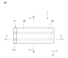
- FIG. 1 is a plan view showing a first embodiment of an elastic device
- FIG. FIG. 2 is a cross-sectional view taken along the line BB of FIG. 1
- 2 is a cross-sectional view taken along line CC of FIG. 1
- FIG. 2B is an enlarged view of area A in FIG. 2A
- FIG. 5 is a graph for explaining the upper surface of the expandable wiring
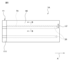
- Fig. 10 is a plan view showing a second embodiment of an elastic device
- FIG. 6 is a cross-sectional view taken along the line BB of FIG. 5
- FIG. 11 is a cross-sectional view showing a third embodiment of an elastic device
- FIG. 8 is an enlarged view of the A region in FIG. 7
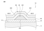
- FIG. 11 is a cross-sectional view showing a fourth embodiment of an elastic device
- FIG. 11 is a cross-sectional view showing a fifth embodiment of an elastic device
- 4 is a graph showing the relationship between L/T and the maximum width of the gap.
- FIG. 1 is a plan view showing a first embodiment of an elastic device
- FIG. 2A is a cross-sectional view taken along the line BB of FIG. 1.
- FIG. 2B is a cross-sectional view taken along line CC of FIG. 1.
- FIG. A stretchable device is used, for example, to be attached to a living body and to measure a biological signal.
- the stretchable device 1 comprises a stretchable stretchable substrate 11 having a major surface 111 and stretchable bases 11 provided on and extending along the major surface 111 . and a covering layer 60 provided on the main surface 111 and covering the expandable wiring 20 .
- the stretchable base material 11 extends in one direction A.
- the stretchable base material 11 is formed in a rectangular shape having long sides along one direction A. As shown in FIG.
- the width of the stretchable base material 11 is preferably constant along the one direction A. The width refers to the length in the direction orthogonal to one direction A.
- the stretchable base material 11 is made of an elastic resin material such as styrene resin, olefin resin, epoxy resin, urethane resin, acrylic resin, or silicone resin, preferably urethane resin.
- Urethane resins include thermoplastic polyurethane (TPU).
- Styrene resins include styrene-butadiene-styrene copolymer resins (SBS).
- the stretch ratio of the stretchable base material 11 is preferably 50% or more. By setting the expansion ratio as described above, the expandable device 1 has good followability to the living body.
- the Young's modulus of the elastic base material 11 is preferably 100 MPa or less, more preferably 30 MPa or less. By setting the Young's modulus as described above, it is possible to suppress the user's discomfort.
- the water absorption rate of the stretchable base material 11 is preferably 1% by weight or less from the viewpoint of ensuring the reliability of the stretchable device 1 more reliably.
- the thickness of the elastic base material 11 is, for example, 0.1 ⁇ m or more and 100 ⁇ m or less.
- the width of the elastic base material 11 is, for example, 10 mm or more and 100 mm or less.
- the expandable wiring 20 is provided on the main surface 111 and extends along the main surface 111 .
- “on the main surface” refers not to an absolute direction such as the vertical direction defined by the direction of gravity, but to an outward direction between the outer side and the inner side of the substrate bounded by the main surface. . Therefore, “on the major surface” is a relative direction determined by the orientation of the major surface.
- “above” an element includes not only the position directly above (on) in contact with the element, but also the position above the element, that is, the position above the element via another object. Also includes a spaced above position.
- the expandable wiring 20 extends along one direction A. It is preferable that a plurality of expandable wirings 20 are present. When a plurality of expandable wires 20 are present, it is preferable that the plurality of expandable wires 20 are arranged side by side in a direction orthogonal to the one direction A, but the arrangement method is not particularly limited. In the first embodiment, two expandable wires 20 exist and are arranged parallel to each other. Note that the expandable wiring 20 does not have to extend in one direction.
- the stretchable wiring 20 is made of a stretchable conductive material.
- a metal foil of silver, copper, nickel, or the like may be used.
- a mixture consisting of The metal powder is preferably silver.
- the average particle size D50 of the metal powder is preferably 0.01 ⁇ m or more and 10 ⁇ m or less.
- the shape of the metal powder may be a spherical shape, a flat shape, an irregular shape having projections, or the like.
- the thickness of the expandable wiring 20 is preferably 100 ⁇ m or less, more preferably 50 ⁇ m or less, and preferably 1 ⁇ m or more, more preferably 10 ⁇ m or more.
- the width of the expandable wiring 20 is preferably 0.2 mm or more.
- the stretchable wiring 20 is formed by screen printing, inkjet printing, dispensing, or the like so as to be in direct contact with the main surface 111 .
- the expansion/contraction wiring 20 may be arranged on the main surface 111 with an insulating protective film (not shown) interposed therebetween.
- the covering layer 60 is a member that protects the expandable wiring 20 from the external environment.
- the covering layer 60 may be a laminate material, a laminate film, or the like.
- the covering layer 60 covers at least part of the expandable wiring 20 .
- the covering layer 60 partially covers the expandable wire 20 so as to expose one end portion of the expandable wire 20 in the extending direction.
- the coating layer 60 preferably has a contact portion 601 that adheres to the stretchable base material 11 at least between adjacent stretchable wires 20 .
- the contact portion 601 can prevent adjacent elastic wires 20 from being connected through a gap.
- the covering layer 60 is an area on the main surface 111 excluding the area where the expandable wiring 20 is provided from the area where the covering layer 60 and the main surface 111 overlap when viewed from the direction perpendicular to the main surface 111. is in close contact with all areas of
- the coating layer 60 is made of an elastic resin material such as ionomer resin, polyester resin, styrene resin, olefin resin, epoxy resin, urethane resin, acrylic resin, or silicone resin, preferably urethane resin.
- Urethane resins include thermoplastic polyurethane (TPU).
- Styrene resins include styrene-butadiene-styrene copolymer resins (SBS).
- the material of the coating layer 60 may be the same as or different from the material of the elastic base material 11 .
- the coating layer 60 may be a film coated with an adhesive to improve adhesion, instead of a thermoplastic resin such as an elastomer resin.
- the thickness of the coating layer 60 is preferably 5 ⁇ m or more, more preferably 10 ⁇ m or more, and preferably 200 ⁇ m or less, more preferably 100 ⁇ m or less.
- the method of forming the coating layer 60 is not particularly limited, but for example, it is formed by pressing (in other words, laminating) a film to be the coating layer 60 onto the stretchable base material 11 with a compression press. After the coating layer 60 is laminated, a vacuum treatment, a pressure treatment, or the like may be performed. Thereby, the adhesion between the covering layer 60 and the stretchable base material 11 and the stretchable wiring 20 can be improved. As a result, the width of the gap that can be formed on the first side surface 203 side and the second side surface 204 side of the expandable wire 20 can be reduced.
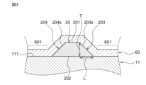
- FIG. 3 is an enlarged view of area A in FIG. 2A.
- FIG. 4 is a graph for explaining the upper surface of the expandable wiring.
- the expandable wiring 20 in a cross section orthogonal to one direction A, which is the extending direction of the expandable wiring 20, the expandable wiring 20 has a top surface 201, a bottom surface 202, and a first side surface connecting the top surface 201 and the bottom surface 202. 203 and a second side 204 .
- the cross-sectional shape of the expandable wiring 20 is trapezoidal.
- Bottom surface 202 is in contact with major surface 111 .
- the covering layer 60 covers the expandable wiring 20 so as to contact the top surface 201 , the first side surface 203 and the second side surface 204 .
- FIG. 4 is a cross-sectional profile of the expansion wiring measured with a CNC three-dimensional measuring device.
- the position of 0 mm height in FIG. 4 corresponds to the position of the main surface of the stretchable base material.
- the upper surface of the expandable wire may have fine irregularities and may not be flat. Therefore, in the present specification, the upper surface of the expandable wire means 70% of the maximum height of the expandable wire in the direction perpendicular to the main surface of the surface of the expandable wire in the cross section perpendicular to the extending direction of the expandable wire. It refers to the surface located above the height.
- the maximum height of the expandable wiring is approximately 0.032 mm
- the surface located at a height of 0.022 mm or higher, which is 70% of the maximum height is defined as the upper surface.
- At least one side surface of the first side surface 203 and the second side surface 204 is inclined such that the width of the expandable wire 20 in the direction parallel to the main surface 111 increases from the top surface 201 side toward the bottom surface 202 side.
- each side of the first side 203 and the second side 204 includes an inclined surface.
- the first side surface 203 includes an inclined surface 203s.
- the second side surface 204 includes an inclined surface 204s.
- the entire first side surface 203 is the inclined surface 203s.
- the entire second side surface 204 is an inclined surface 204s.
- the inclined surface 203s and the inclined surface 204s are not particularly limited in shape as long as they are inclined so that the width of the expandable wiring 20 in the direction parallel to the main surface 111 increases from the top surface 201 side toward the bottom surface 202 side.
- the inclined surface 203s and the inclined surface 204s are flat as a whole, but may be a convex curved surface projecting to the outside of the expandable wire 20, or a concave curved surface recessed to the inside of the expandable wire 20. It may be a meandering curved surface combining a convex curved surface and a concave curved surface, or a shape combining these curved surfaces and a flat surface.
- each side of the first side 203 and the second side 204 includes an inclined surface 203s and an inclined surface 204s, respectively.
- Each of the inclined surface 203s and the inclined surface 204s is inclined such that the width of the expandable wire 20 in the direction parallel to the main surface 111 of the expandable base material 11 increases from the upper surface 201 side of the expandable wire 20 toward the bottom surface 202 side. are doing. Therefore, the covering layer 60 can easily follow the shape of the expandable wiring 20, and the adhesion of the covering layer 60 can be improved. Therefore, formation of a gap between the first side surface 203 and the second side surface 204 of the expandable wire 20 and the coating layer 60 can be suppressed. As a result, ion migration or the like of the expandable wiring 20 can be suppressed, and the reliability of the expandable wiring 20 can be ensured.
- each of the first side surface 203 and the second side surface 204 includes the inclined surface 203s and the inclined surface 204s, the expansion and contraction is greater than when one of the first side surface 203 and the second side surface 204 includes the inclined surface.
- the adhesion of the covering layer 60 to the wiring 20 is improved, and the reliability of the expandable wiring 20 can be ensured more reliably.
- each side surface of the first side surface 203 and the second side surface 204 is entirely inclined, the adhesion of the coating layer 60 to the expandable wire 20 is improved more than when the side surface is partially inclined. As a result, the reliability of the expandable wiring 20 can be ensured more reliably.
- the height of the inclined surface 203s in the direction orthogonal to the main surface 111 is T
- the width of the inclined surface 203s in the direction parallel to the main surface 111 is Let be L.
- the direction A in the direction orthogonal to the principal surface 111 is assumed to be A.
- B is the distance T.
- L is the distance between A and B in the direction parallel to the main surface 111 .
- the upper surface of the expandable wire 20 may have fine unevenness and may not be flat. Therefore, T is not necessarily the highest portion of the upper surface of the expandable wire 20 in the direction perpendicular to the main surface 111 .
- the sloped surface on at least one of the first side surface 203 and the second side surface 204 satisfies L/T>3.
- the central portion of the expandable wiring 20 in the extending direction may be observed.
- the adhesion of the covering layer 60 to the expandable wiring 20 is effectively improved, and the reliability of the expandable wiring 20 can be ensured more reliably.
- the longest part of the expandable wiring 20 in the direction parallel to the main surface 111 is the bottom surface of the expandable wiring 20 .
- the coating layer 50 can adhere to the entire inclined surfaces 203s and 204s of the expandable wiring 20, so ion migration can be suppressed.
- each side of the first side 203 and the second side 204 includes an inclined surface, and all inclined surfaces satisfy L/T>3.
- the adhesion of the covering layer 60 to the expandable wiring 20 is more effectively improved, and the reliability of the expandable wiring 20 can be more reliably ensured.
- the water absorption rate of the coating layer 60 is smaller than the water absorption rate of the elastic base material 11,
- the water absorption of the coating layer 60 is 1% by weight or less.
- both the elastic base material 11 and the coating layer 60 have a water absorption rate of 1% by weight or less.
- the Young's modulus of the covering layer 60 is smaller than the Young's modulus of the elastic wiring 20 .
- the Young's modulus of the coating layer 60 is 100 MPa or less.
- the reliability of the expandable wiring 20 can be ensured more reliably.
- FIG. 5 is a plan view showing a second embodiment of an elastic device.
- FIG. 6 is a cross-sectional view along BB in FIG. 2nd Embodiment differs from 1st Embodiment in that the space
- the covering layer 60 is in contact with a portion of the stretchable wiring 20, and is in contact with at least one of the first side surface 203 and the second side surface 204. and the covering layer 60. Further, a gap 70 is provided between the . Specifically, in this embodiment, the covering layer 60 is in contact with the upper surface 201 and the second side surface 204 of the expandable wire 20 , and has a gap 70 between the first side surface 203 and the covering layer 60 .
- the maximum width L2 of the gap 70 in the direction perpendicular to the extending direction of the expandable wiring 20 when viewed from the direction perpendicular to the main surface 111 is 10 ⁇ m or more and 100 ⁇ m or less.
- L2 is also referred to as "maximum width of the gap". From the viewpoint of ensuring reliability, it is preferable that the maximum width L2 of the gap 70 is as small as possible.
- the maximum width of the void refers to the maximum width of the void in the extending direction of the stretchable wire in the direction orthogonal to the extending direction of the stretchable wire when viewed from the direction orthogonal to the main surface of the stretchable base material.
- the size of the gap 70 is limited, thereby suppressing deterioration of the reliability of the expandable wiring 20. , and the reliability of the expandable wiring 20 can be ensured.
- the coating layer 60 has an inclined portion 602 that covers at least one of the first side surface 203 and the second side surface 204 and that is inclined with respect to the direction perpendicular to the main surface 111 .
- the coating layer 60 has an inclined portion 602 that covers the first side surface 203 and is inclined with respect to the direction perpendicular to the main surface 111 .
- the boundary between the inclined portion 602 and other portions of the coating layer 60 is indicated by a chain double-dashed line for the sake of convenience.
- T1 be the height of the inclined portion 602 in the direction perpendicular to the main surface 111 and L1 be the width of the inclined portion 602 in the direction parallel to the main surface 111 in the cross section perpendicular to the extending direction of the expandable wiring 20 .
- the height of the inclined portion is the main surface of the inner surface of the inclined portion (in other words, the surface of the inclined portion facing the inclined surface of the expandable wire) in the cross section perpendicular to the extending direction of the expandable wire. It refers to the height in the direction perpendicular to 111 .
- the width of the inclined portion means the main surface 111 of the inner surface of the inclined portion (in other words, the surface of the inclined portion facing the inclined surface of the expandable wire) in the cross section orthogonal to the extending direction of the expandable wire. refers to the width in the direction parallel to
- the height T1 of the inclined portion 602 is equal to the height T of the inclined surface 203s
- the width L1 of the inclined portion 602 is greater than the width L of the inclined surface 203s.
- L/T ⁇ L1/T1 ⁇ 2 ⁇ L/T is satisfied on the side of the first side 203 and the second side 204 where the gap exists, that is, on the side of the first side 203 in this embodiment. .
- FIG. 7 is a cross-sectional view showing a third embodiment of an elastic device.
- FIG. 8 is an enlarged view of area A in FIG.
- the third embodiment differs from the first embodiment in that a first protective layer is provided. This different configuration is described below. The rest of the configuration is the same as that of the first embodiment, and the same reference numerals as those of the first embodiment are given, and the description thereof is omitted. Note that FIG. 7 corresponds to FIG. 2A of the first embodiment.
- the stretchable device 1B according to the third embodiment further includes a first protective layer 81 on the main surface 111.
- the first protective layer 81 is positioned between the main surface 111 and the bottom surface 202 of the expandable wiring 20, and is in contact with the main surface 111 and the bottom surface 202.
- the covering layer 60 has a contact portion 601 ⁇ /b>B that contacts the first protective layer 81 at least between adjacent elastic wires 20 .
- the first protective layer 81 is made of a material with low water absorption, such as an acrylic UV curable resin.
- the first protective layer 81 can be formed by printing. Note that the first protective layer 81 may be made of a silicone-based, polyester-based, urethane-based resin material, or the like.
- the first protective layer 81 since the first protective layer 81 is provided, it is possible to suppress the occurrence of ion migration and the like in the stretchable wiring 20 due to penetration of moisture from the stretchable base material 11 side. As a result, the reliability of the expandable wiring 20 can be ensured more reliably.
- the contact portion 601B since the contact portion 601B is provided, it is possible to prevent the adjacent flexible wirings 20 from being connected through a gap. As a result, it is possible to suppress ion migration or the like that may occur between the adjacent expandable wires 20 and ensure the reliability of the expandable wires 20 .
- the first protective layer 81 may be provided only at positions corresponding to the bottom surfaces 202 of the respective flexible wirings 20 .
- the first protective layer 81 is provided on the bottom surface 202 of each flexible wire 20, and the first protective layers 81 provided on the bottom surface 202 of each flexible wire 20 are separated from each other. .
- the coating layer 60 is in close contact with the main surface 111 of the stretchable substrate 11 on which the first protective layer 81 is not provided.
- FIG. 9 is a cross-sectional view showing a fourth embodiment of an elastic device.
- the fourth embodiment differs from the third embodiment in that a second protective layer is provided. This different configuration is described below. The rest of the configuration is the same as that of the third embodiment, and the same reference numerals as those of the third embodiment are given, and the description thereof is omitted.
- FIG. 9 corresponds to FIG. 3 of the first embodiment.
- the stretchable device 1C further includes a second protective layer 82 covering the stretchable wiring 20.
- the second protective layer 82 is positioned between the expandable wire 20 and the covering layer 60 and is positioned between the upper surface 201 , the first side surface 203 and the second side surface 204 of the expandable wire 20 . are in contact with
- the covering layer 60 has a contact portion 601 ⁇ /b>C that contacts the second protective layer 82 at least between adjacent stretchable wires 20 .
- the second protective layer 82 is made of a material with low water absorption, such as an acrylic UV curable resin.
- the second protective layer 82 may be a silicone, polyester, or urethane resin material.
- the constituent material of the second protective layer 82 may be the same as or different from the constituent material of the first protective layer 81 .
- the second protective layer 82 can be formed by printing. Therefore, unlike the covering layer 60 , the second protective layer 82 easily conforms to the shape of the expandable wiring 20 . As a result, the second protective layer 82 can cover the expandable wire 20 while contacting the entire outer surface of the expandable wire 20 . In addition, since the cross-sectional shape of the expandable wire 20 is trapezoidal, the adhesion between the second protective layer 82 and the covering layer 60 is improved.
- the second protective layer 82 since the second protective layer 82 is provided, it is possible to suppress the occurrence of ion migration and the like in the expandable wiring 20 due to penetration of moisture from the covering layer 60 side. As a result, the reliability of the expandable wiring 20 can be ensured more reliably.
- the adhesive portion 601C since the adhesive portion 601C is provided, it is possible to prevent the adjacent flexible wirings 20 from being connected through a gap. As a result, it is possible to suppress ion migration or the like that may occur between the adjacent expandable wires 20 and ensure the reliability of the expandable wires 20 .
- FIG. 10 is a cross-sectional view showing a fifth embodiment of an elastic device. 5th Embodiment differs from 4th Embodiment in that the space
- the covering layer 60 is in contact with part of the second protective layer 82, and is in contact with at least one of the first side surface 203 and the second side surface 204.
- a gap 70 is further provided between the portion of the second protective layer 82 contacting the first side surface 203 and the second side surface 204 and the covering layer 60 .
- the covering layer 60 includes the portion of the second protective layer 82 contacting the upper surface 201 of the expandable wire 20 and the portion of the second protective layer 82 contacting the second side surface 204 . and at least the portion of the second protective layer 82 contacting the first side surface 203 and the covering layer 60 .
- the maximum width of the gap 70 in the direction perpendicular to the extension direction of the expandable wiring 20 when viewed from the direction perpendicular to the main surface 111 is 10 ⁇ m or more and 100 ⁇ m or less.
- the maximum value of this width is the same as L2 described in FIG. 5 of the second embodiment.
- the size of the gap 70 is limited, so the reliability of the expandable wire 20 is lowered. can be suppressed, and the reliability of the expandable wiring 20 can be ensured.
- the covering layer 60 has an inclined portion 602 that covers at least one of the first side surface 203 and the second side surface 204 and that is inclined with respect to the direction perpendicular to the main surface 111 .
- the coating layer 60 has an inclined portion 602 that covers the first side surface 203 and is inclined with respect to the direction perpendicular to the main surface 111 .
- the boundary between the inclined portion 602 and other portions of the coating layer 60 is indicated by a chain double-dashed line for the sake of convenience.
- T1 be the height of the inclined portion 602 in the direction perpendicular to the main surface 111 and L1 be the width of the inclined portion 602 in the direction parallel to the main surface 111 in the cross section perpendicular to the extending direction of the expandable wiring 20 .
- T1 means the maximum height of the inclined portion 602 in the direction orthogonal to the main surface 111 in the cross section orthogonal to the extending direction of the expandable wiring 20 .
- L1 means the maximum width of the inclined portion 602 in the direction parallel to the main surface 111 in the cross section orthogonal to the extending direction of the expandable wiring 20 .
- L/T ⁇ L1/T1 ⁇ 2 ⁇ L/T is satisfied on the side of the first side 203 and the second side 204 where the gap exists, that is, on the side of the first side 203 in this embodiment. .
- the gap 70 exists between the second protective layer 82 and the covering layer 60, the deterioration of the reliability of the expandable wiring 20 can be suppressed, and the reliability of the expandable wiring 20 can be secured.
- the stretchable base material has a rectangular shape in the above embodiment, it is not limited to a rectangular shape, and may have, for example, a polygonal shape, an elliptical shape, or an oval shape.
- the expandable wiring extends linearly in one direction, but is not limited to this, and may meander or branch, for example.
- a plurality of expandable wires are arranged parallel to each other, but they do not have to be parallel.
- the expandable wiring is provided only on one main surface of the expandable base material, but may be provided on the other main surface facing the main surface. In this case, a covering layer is also provided on the main surface on the other side so as to cover the expandable wiring.
- the inclined surface is provided on each of the first side surface and the second side surface of the expandable wiring. good too.
- the entire first side surface and the entire second side surface are the inclined surfaces, but a part of the first side surface and/or a part of the second side surface may be the inclined surfaces.
- the first side surface and/or the second side surface connect the inclined surface connected to the upper surface of the expandable wiring and the bottom surface of the expandable wiring and the inclined surface.
- the coating layer is a laminate film or the like, it follows the inclined surface that is inclined so that the width of the expandable wire in the direction parallel to the main surface increases as it goes from the upper surface side to the bottom surface side of the expandable wire. It's easy to do. Therefore, in the case of the above configuration, there may be a portion on the side surface of the expandable wire where the side surface and the covering layer are not in contact with each other. In other words, in the case of the above configuration, in the cross section orthogonal to the extending direction of the expandable wire, the width of the expandable wire in the direction parallel to the main surface decreases from the upper surface side to the bottom surface side of the covering layer and the expandable wire. A gap may occur between the inclined surface and the inclined surface.
- the covering layer covers a part of the outer surface of the expandable wire so that one end of the expandable wire is exposed. It is not limited, and may cover the entire outer surface of the expandable wire.
- the gap portion is provided only on the first side surface of the expandable wire, but may be provided only on the second side surface, or may be provided on both the first side surface side and the second side surface side. Both may be provided.
- first protective layer and the second protective layer are provided in the fourth embodiment, only the second protective layer may be provided.
- the gap is provided only on the first side of the expandable wire, but it may be provided only on the second side, or on both the first side and the second side. Both may be provided.
- Example 1 Measurement of the maximum width of the gap and reliability tests were performed for stretchable devices having various inclinations (L/T) of the slanted surface of the stretchable wiring.
- ⁇ Stretchable base material> A styrene-butadiene-styrene resin (SBS) was used for the stretchable substrate.
- SBS styrene-butadiene-styrene resin
- the water absorption rate of SBS at 40° C. and 93% RH is 0.1 wt. % or less.
- ⁇ Expansion wiring> For the stretchable wiring, a plurality of conductive pastes containing a mixture of silver and an acrylic resin were printed on the stretchable base material using a screen printing method or the like. After that, the stretchable wiring was formed into a desired shape by thermally curing the conductive paste so as to obtain a predetermined resistance value. A plurality of expandable wires were formed in parallel with each other, the gap between the wires was 200 ⁇ m, and the wire length was 100 mm. The expansion/contraction wiring was formed to have a trapezoidal cross section by coating the expansion/contraction wiring with different line widths multiple times and by appropriately selecting the viscosity. The cross-sectional shape of the expandable wiring, that is, the height T of the inclined surface and the width L of the inclined surface were changed for each sample by changing the specifications of the dispenser and the printing plate for screen printing.
- a covering layer was formed on the stretchable base material on which the stretchable wiring was formed. Specifically, a coating layer was formed by laminating a film obtained by applying an acrylic pressure-sensitive adhesive to a polyurethane resin on a stretchable base material. The temperature and pressure conditions during lamination were set in consideration of the melting point and the like so that water would not enter from the contact surface with the elastic base material.
- ⁇ Reliability test> In the fabricated sample, the stretchable wiring was connected to a DC power supply set to 5V, and the reliability was evaluated. The samples were immersed in water at 30°C. In the reliability test, the short-circuit time was defined as the time when the insulation resistance of the stretchable base material and the coating layer fell below 1 M ⁇ due to ion migration and water absorption. Since the stretchable device of this embodiment is assumed to be mainly used as a disposable device, a reliability test was conducted for a maximum of one week (168 hours). A sample that did not cause ion migration or the like even after 168 hours, that is, a sample that had a short-circuit time of 168 hours or longer was regarded as acceptable. Table 1 shows the test results.
- Example 2 A reliability test was conducted by changing the material of the coating layer. The same base material as in Example 1 was used as the stretchable base material. Table 2 shows the test results.
- polyester resins, styrene-butadiene-styrene resins, polyurethane resins + acrylic adhesives, etc. have a water absorption rate of 1% by weight or less, and have a short-circuit time of 168 hours or more. Got. No appearance of dendrite due to ion migration was confirmed. On the other hand, with the modified polyurethane resin having a high water absorption rate, ion migration occurred and the insulation resistance deteriorated after 2 hours. It was confirmed that good reliability can be obtained if the water absorption rate of the coating layer is 1.0% by weight or less.
- Example 3 We investigated the relationship between the hardness of the coating layer and the plastic deformation of the stretchable wiring.
- Table 3 shows the test results for the Young's modulus of the coating layer and the gap between the stretchable wires after pressing the coating layer to the stretchable base material.
- the expansion/contraction wire gap means the distance between adjacent expansion/contraction wires.
- the stretchable wiring gap was measured with an optical microscope.
- the elastic wire had a Young's modulus of about 100 MPa.
- the Young's modulus of the coating layer when the Young's modulus of the coating layer is higher than the Young's modulus of the flexible wiring, the flexible wiring is plastically deformed, and the gap between the flexible wiring becomes smaller. This increases the possibility of ion migration occurring between adjacent stretchable wirings. Therefore, it was confirmed that the Young's modulus of the covering layer should be smaller than the Young's modulus of the expandable wire, specifically 100 MPa or less, so that the expandable wire is not plastically deformed.
- stretchable device 11 stretchable base material 111 main surface 20 stretchable wiring 201 upper surface 202 bottom surface 203 first side surface 204 second side surface 60 coating layer 601, 601B, 601C adhesion portion 602 inclined portion 70 void portion 81 first protective layer 82 second 2 Protective layer T Height of inclined surface L Width of inclined surface T1 Height of inclined portion L1 Width of inclined portion L2 Maximum width of gap
Landscapes
- Engineering & Computer Science (AREA)
- Microelectronics & Electronic Packaging (AREA)
- Manufacturing & Machinery (AREA)
- Structure Of Printed Boards (AREA)
- Non-Metallic Protective Coatings For Printed Circuits (AREA)
- Insulated Conductors (AREA)
Priority Applications (2)
| Application Number | Priority Date | Filing Date | Title |
|---|---|---|---|
| JP2023566093A JP7582514B2 (ja) | 2021-12-08 | 2022-09-13 | 伸縮デバイス |
| CN202290000778.0U CN222030115U (zh) | 2021-12-08 | 2022-09-13 | 伸缩器件 |
Applications Claiming Priority (2)
| Application Number | Priority Date | Filing Date | Title |
|---|---|---|---|
| JP2021-199588 | 2021-12-08 | ||
| JP2021199588 | 2021-12-08 |
Publications (1)
| Publication Number | Publication Date |
|---|---|
| WO2023105873A1 true WO2023105873A1 (ja) | 2023-06-15 |
Family
ID=86730101
Family Applications (1)
| Application Number | Title | Priority Date | Filing Date |
|---|---|---|---|
| PCT/JP2022/034267 Ceased WO2023105873A1 (ja) | 2021-12-08 | 2022-09-13 | 伸縮デバイス |
Country Status (3)
| Country | Link |
|---|---|
| JP (1) | JP7582514B2 (https=) |
| CN (1) | CN222030115U (https=) |
| WO (1) | WO2023105873A1 (https=) |
Cited By (1)
| Publication number | Priority date | Publication date | Assignee | Title |
|---|---|---|---|---|
| WO2025192205A1 (ja) * | 2024-03-15 | 2025-09-18 | 株式会社サトー | 導電パターンを備えた基材、電子デバイス、電磁波シールドフィルムおよび面状発熱体 |
Citations (4)
| Publication number | Priority date | Publication date | Assignee | Title |
|---|---|---|---|---|
| US20170169918A1 (en) * | 2015-12-10 | 2017-06-15 | Electronics And Telecommunications Research Institute | Stretchable wire and method of fabricating the same |
| WO2018012013A1 (ja) * | 2016-07-12 | 2018-01-18 | 株式会社フジクラ | 伸縮性基板 |
| JP2018148150A (ja) * | 2017-03-09 | 2018-09-20 | 株式会社フジクラ | 伸縮性基板及びその製造方法 |
| WO2019031302A1 (ja) * | 2017-08-10 | 2019-02-14 | 積水ポリマテック株式会社 | 伸縮配線 |
Family Cites Families (1)
| Publication number | Priority date | Publication date | Assignee | Title |
|---|---|---|---|---|
| JP5448736B2 (ja) * | 2008-11-18 | 2014-03-19 | 東海ゴム工業株式会社 | 導電膜、およびそれを備えたトランスデューサ、フレキシブル配線板 |
-
2022
- 2022-09-13 JP JP2023566093A patent/JP7582514B2/ja active Active
- 2022-09-13 CN CN202290000778.0U patent/CN222030115U/zh active Active
- 2022-09-13 WO PCT/JP2022/034267 patent/WO2023105873A1/ja not_active Ceased
Patent Citations (4)
| Publication number | Priority date | Publication date | Assignee | Title |
|---|---|---|---|---|
| US20170169918A1 (en) * | 2015-12-10 | 2017-06-15 | Electronics And Telecommunications Research Institute | Stretchable wire and method of fabricating the same |
| WO2018012013A1 (ja) * | 2016-07-12 | 2018-01-18 | 株式会社フジクラ | 伸縮性基板 |
| JP2018148150A (ja) * | 2017-03-09 | 2018-09-20 | 株式会社フジクラ | 伸縮性基板及びその製造方法 |
| WO2019031302A1 (ja) * | 2017-08-10 | 2019-02-14 | 積水ポリマテック株式会社 | 伸縮配線 |
Cited By (1)
| Publication number | Priority date | Publication date | Assignee | Title |
|---|---|---|---|---|
| WO2025192205A1 (ja) * | 2024-03-15 | 2025-09-18 | 株式会社サトー | 導電パターンを備えた基材、電子デバイス、電磁波シールドフィルムおよび面状発熱体 |
Also Published As
| Publication number | Publication date |
|---|---|
| JP7582514B2 (ja) | 2024-11-13 |
| CN222030115U (zh) | 2024-11-19 |
| JPWO2023105873A1 (https=) | 2023-06-15 |
Similar Documents
| Publication | Publication Date | Title |
|---|---|---|
| CN107211534B (zh) | 伸缩性电路基板 | |
| JP6491556B2 (ja) | 配線回路基板 | |
| JP6484133B2 (ja) | 配線回路基板の製造方法 | |
| US11987031B2 (en) | Protection tape for printed circuit board and display device including the same | |
| US6753613B2 (en) | Stacked dice standoffs | |
| WO2023105873A1 (ja) | 伸縮デバイス | |
| JP6449111B2 (ja) | シールド材、電子部品及び接着シート | |
| WO2020004660A1 (ja) | 伸縮配線部材 | |
| CN110708860A (zh) | 一种柔性电路板 | |
| WO2018168734A1 (ja) | 電子部品内蔵樹脂構造体及びその製造方法 | |
| TW200847374A (en) | Bump structure | |
| TW200941864A (en) | Contact structure and connecting structure | |
| JPWO2016151898A1 (ja) | 接続シート、フレキシブルフラットケーブル、フレキシブルフラットケーブルの接続構造及びフレキシブルフラットケーブルの接続方法 | |
| JP6771102B2 (ja) | スイッチ | |
| JP2011108922A (ja) | 回路基板 | |
| JP7563632B2 (ja) | 伸縮配線基板 | |
| US12526915B2 (en) | Stretchable device | |
| CN118678529B (zh) | 具有电磁屏蔽的软性线路板及其制造方法 | |
| US20250294677A1 (en) | Resin multilayer substrate and electronic device | |
| US9293399B2 (en) | Semiconductor device and electronic unit provided with the same | |
| WO2025192170A1 (ja) | 伸縮性デバイス | |
| KR20230046154A (ko) | 3층 연성적층판, 그 제조방법 및 이를 적용한 전기접촉단자 | |
| JP2009212270A (ja) | 半導体装置 | |
| JP2010153579A (ja) | リードフレーム | |
| JP2019071188A (ja) | フレキシブルフラットケーブル及び接続構造 |
Legal Events
| Date | Code | Title | Description |
|---|---|---|---|
| 121 | Ep: the epo has been informed by wipo that ep was designated in this application |
Ref document number: 22903808 Country of ref document: EP Kind code of ref document: A1 |
|
| WWE | Wipo information: entry into national phase |
Ref document number: 2023566093 Country of ref document: JP |
|
| WWE | Wipo information: entry into national phase |
Ref document number: 202290000778.0 Country of ref document: CN |
|
| NENP | Non-entry into the national phase |
Ref country code: DE |
|
| 122 | Ep: pct application non-entry in european phase |
Ref document number: 22903808 Country of ref document: EP Kind code of ref document: A1 |