WO2023105700A1 - 更新判定装置及び更新判定方法 - Google Patents
更新判定装置及び更新判定方法 Download PDFInfo
- Publication number
- WO2023105700A1 WO2023105700A1 PCT/JP2021/045230 JP2021045230W WO2023105700A1 WO 2023105700 A1 WO2023105700 A1 WO 2023105700A1 JP 2021045230 W JP2021045230 W JP 2021045230W WO 2023105700 A1 WO2023105700 A1 WO 2023105700A1
- Authority
- WO
- WIPO (PCT)
- Prior art keywords
- update
- acquisition unit
- determined
- determination device
- control unit
- Prior art date
- Legal status (The legal status is an assumption and is not a legal conclusion. Google has not performed a legal analysis and makes no representation as to the accuracy of the status listed.)
- Ceased
Links
Images


Classifications
-
- B—PERFORMING OPERATIONS; TRANSPORTING
- B60—VEHICLES IN GENERAL
- B60R—VEHICLES, VEHICLE FITTINGS, OR VEHICLE PARTS, NOT OTHERWISE PROVIDED FOR
- B60R16/00—Electric or fluid circuits specially adapted for vehicles and not otherwise provided for; Arrangement of elements of electric or fluid circuits specially adapted for vehicles and not otherwise provided for
- B60R16/02—Electric or fluid circuits specially adapted for vehicles and not otherwise provided for; Arrangement of elements of electric or fluid circuits specially adapted for vehicles and not otherwise provided for electric constitutive elements
Definitions
- the present disclosure relates to an update determination device and an update determination method.
- a device has been proposed that updates the program of the equipment of the vehicle when the driver of the vehicle can manually drive the vehicle (for example, Patent Document 1).
- the program can be updated even when the ignition of the vehicle is not turned off, so it is possible to speed up the update and shorten the waiting time of the passenger for the update.
- the present disclosure has been made in view of the problems described above, and aims to provide a technology that can suppress careless driving by the driver.
- An update determination device includes an acquisition unit that acquires an image of the interior of a vehicle and an update program for updating the program of a device other than the device used for manual driving by the driver of the vehicle; Control for determining that the program can be updated by the update program acquired by the acquisition unit when it is determined that one or more fellow passengers are present in a seat other than the driver's seat of the vehicle based on the acquired image. and a part.
- the present disclosure when it is determined that one or more passengers are in a seat other than the driver's seat of the vehicle based on the acquired image, it is possible to update the program by the acquired update program. Since the determination is made, careless driving by the driver can be suppressed.
- FIG. 1 is a block diagram showing the configuration of an update determination device according to Embodiment 1;
- FIG. FIG. 9 is a block diagram showing the configuration of an update determination device according to Embodiment 2;
- FIG. 10 is a diagram showing an example of an image acquisition unit according to Embodiment 2;
- FIG. 10 is a diagram showing an example of an image according to Embodiment 2;
- FIG. 10 is a diagram showing an example of an image according to Embodiment 2;
- FIG. FIG. 11 is a diagram for explaining an operation example of a feature point detection unit according to Embodiment 2;
- FIG. 11 is a diagram for explaining an operation example of a feature point detection unit according to Embodiment 2;
- FIG. 11 is a diagram for explaining an operation example of a feature point detection unit according to Embodiment 2;
- FIG. 10 is a diagram showing an operation example of a feature point detection unit according to Embodiment 2;
- FIG. 11 is a diagram for explaining an operation example
- FIG. 11 is a diagram for explaining an operation example of a feature point detection unit according to Embodiment 2;
- FIG. 10 is a diagram for explaining an operation example of a face information analysis unit according to Embodiment 2;
- FIG. 10 is a diagram for explaining an operation example of a face information analysis unit according to Embodiment 2;
- FIG. 10 is a diagram for explaining an operation example of a face information analysis unit according to Embodiment 2;
- FIG. 10 is a diagram showing a display example of the update determination device according to Embodiment 2;
- 9 is a flow chart showing the operation of the update determination device according to Embodiment 2;
- FIG. 11 is a block diagram showing the configuration of an update determination device according to Modification 3; 14 is a flowchart showing the operation of an update determination device according to modification 3; FIG. 11 is a block diagram showing a hardware configuration of an update determination device according to another modified example; FIG. 11 is a block diagram showing a hardware configuration of an update determination device according to another modified example; FIG. 11 is a block diagram showing the configuration of a server according to another modified example; FIG. 11 is a block diagram showing the configuration of a communication terminal according to another modified example;
- FIG. 1 is a block diagram showing the configuration of an update determination device 1 according to the first embodiment.
- the update determination device 1 of FIG. 1 includes an acquisition unit 11 and a control unit 12 .
- the update determination device 1 may be applied to a DMS (Driver Monitoring System) or the like provided inside the vehicle, or may be provided outside the vehicle as described later.
- DMS Driver Monitoring System
- the acquisition unit 11 acquires an image of the interior of the vehicle.
- a camera and its interface device are used for the function of acquiring an image of the interior of the vehicle.
- the acquisition unit 11 also acquires an update program for updating the programs of the devices other than the devices used for manual driving by the driver of the vehicle.
- equipment used for manual driving by the driver of the vehicle may be referred to as "manual driving equipment”.
- Devices other than the devices for manual operation are, for example, devices mainly used for automatic driving, cameras, wireless communication devices, and the like.
- the update program acquisition function includes, for example, a wireless communication device that wirelessly communicates with a server, a device that reads the update program from a storage medium such as a USB memory storing the update program, and an interface device for them.
- the control unit 12 determines whether or not there is one or more fellow passengers in a seat other than the driver's seat of the vehicle.
- Seats other than the driver's seat of the vehicle are, for example, a passenger seat and a rear seat.
- the term "occupant" may be used when the driver and fellow passengers are not distinguished from each other.
- control unit 12 determines that the update program acquired by the acquisition unit 11 can be used to update the program. On the other hand, when it is determined that there is no fellow passenger, the control unit 12 determines that the program cannot be updated by the update program acquired by the acquisition unit 11 .
- control unit 12 may perform the update. Control may be performed to display the determination result as to whether it is possible or not.
- ⁇ Summary of Embodiment 1> According to the update determination device 1 according to the first embodiment as described above, when it is determined that one or more fellow passengers are present in a seat other than the driver's seat of the vehicle, the program is updated by the obtained update program. is possible. According to such a configuration, it is possible to allow a passenger other than the driver, that is, a fellow passenger, to determine whether updating by the update program is possible or not, so careless driving by the driver can be suppressed. In addition, since the program can be updated even when the ignition of the vehicle is not turned off, it is possible to speed up the update and shorten the waiting time of the passenger for the update.
- FIG. 2 is a block diagram showing the configuration of the update determination device 1 according to the second embodiment.
- constituent elements that are the same as or similar to the above-described constituent elements are denoted by the same or similar reference numerals, and different constituent elements will be mainly described.
- the update determination device 1 in FIG. 2 is connected to the device control unit 18 and the display unit 19 by wire or wirelessly so as to be communicable.
- the equipment control unit 18 controls the equipment of the vehicle based on a program stored in the memory of the vehicle.
- the device control unit 18 is, for example, an ECU (Electronic Control Unit).
- the display unit 19 performs various displays under the control of the update determination device 1.
- the display unit 19 is, for example, a display device such as a liquid crystal display device or a head-up display (HUD).
- the display unit 19 may be a display device integrated with the vehicle, or may be a display device brought into the vehicle.
- the update determination device 1 does not include the device control unit 18 and the display unit 19, but may include the device control unit 18 and the display unit 19.
- the update determination device 1 of FIG. 2 includes an image acquisition unit 11a, an update information acquisition unit 11b, an operation acquisition unit 11c, a feature point detection unit 12a, a face information analysis unit 12b, an update control unit 12c, and an HMI ( Human Machine Interface) control unit 12d.
- image acquisition unit 11a, the update information acquisition unit 11b, and the operation acquisition unit 11c are included in the concept of the acquisition unit 11 in FIG.
- the feature point detection unit 12a, the face information analysis unit 12b, the update control unit 12c, and the HMI control unit 12d are included in the concept of the control unit 12 in FIG.
- the image acquisition unit 11a acquires an image of the interior of the vehicle.
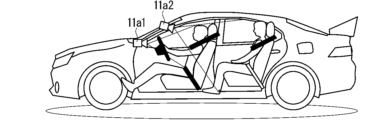
- the image acquisition unit 11a according to the second embodiment includes an instrument panel center camera 11a1 and an OHC (overhead console) camera 11a2 shown in FIG.
- the instrument panel center camera 11a1 is provided at the center of the instrument panel of the vehicle, and as shown in FIG. It is possible.
- the OHC camera 11a2 is provided on the OHC of the vehicle, and as shown in FIG. Shooting is possible.
- the image acquisition unit 11a may include either one of the instrument panel center camera 11a1 and the OHC camera 11a2, or may include cameras other than these. Further, the image acquisition unit 11a may change the brightness of the image to a predetermined brightness in consideration of the influence of the sunlight incident on the vehicle, or may acquire the image at a constant cycle.
- the update information acquisition unit 11b receives (that is, acquires) an update program from the server 61 for updating the programs of devices other than the devices for manual operation.
- the update information acquisition unit 11b is, for example, a wireless communication device.
- the server 61 includes a CPU (Central Processing Unit), memory, and an interface, all of which are not shown, and update programs are stored in the memory.
- the update determination device 1 determines whether the update program has been sent to the server 61. Recognize whether it exists or not. Then, when the update determination device 1 recognizes that the update program exists in the server 61 , the update information acquisition unit 11 b downloads the update program from the server 61 . Note that the update information acquisition unit 11b may be the target of the update program.
- the operation acquisition unit 11c acquires an update operation from the driver or fellow passenger.
- a touch panel may be used as the operation acquisition unit 11c, or an image recognition device capable of acquiring the gesture operation of the driver or the passenger based on the image acquired by the image acquisition unit 11a may be used. Alternatively, those interface devices may be used.
- the gesture operation may be an act of trying to update the program using the update program.
- the operation acquisition unit 11c is a touch panel, it may be included in the HMI control unit 12d.
- the feature point detection unit 12a detects the seat position of the vehicle based on the image acquired by the image acquisition unit 11a.
- the feature point detection unit 12a detects the area of the face image of the passenger sitting in each seat based on the image acquired by the image acquisition unit 11a. For example, when the image acquisition unit 11a acquires an image including a face image 21 as shown in FIG. 6, the feature point detection unit 12a detects a face image area 22 as shown in FIG.
- the feature point detection unit 12a detects feature points 23 for facial parts such as the eyes, nose, and mouth from the face image area 22. For example, when a face image area 22 as shown in FIG. 7 is detected, the feature point detection unit 12a detects a plurality of feature points 23 as shown in FIG. 6 to 8, the face image area 22 and the feature points 23 are detected for the driver who operates the steering wheel 20, but the face image area 22 and the feature points 23 are similarly detected for the fellow passenger. .
- the face information analysis section 12b determines at least one of the face direction, the line of sight direction, and the degree of eye opening/closing. Detect as face information. In the second embodiment, face information is detected for each passenger.
- the plurality of feature points 23 are inner corners 23a and 23e, outer corners 23b and 23f, upper eyelids 23c and 23g, lower eyelids 23d and 23h, nasal root 23i, and nasal tip 23j. , the wings of the nose 23k, the corners of the mouth 23l, 23m, and the center of the lips 23n.
- the feature points 23 are not limited to these, and may include, for example, the cornea, the back of the nose, the upper lip, the lower lip, and the like.
- the face information analysis unit 12b detects left as the face orientation of the face image 21 when the tip of the nose 23j is positioned to the left of the outer corner of the eye 23b.
- the face information analysis unit 12b detects that the face of the face image 21 faces upward, and the tip of the nose 23j If the face is positioned below the line, the downward direction is detected as the face orientation of the face image 21 .
- the face information analysis unit 12b detects that the face of the face image 21 is facing right when the tip of the nose 23j is located on the right side of the corner of the eye 23f.
- the face information analysis unit 12b detects the degree of eye openness based on the distance between the upper eyelids 23c, 23g and the lower eyelids 23d, 23h.
- the face information analysis unit 12b detects the direction of the line of sight based on the positional relationship among the cornea, inner corners 23a and 23e, outer corners 23b and 23f, upper eyelids 23c and 23g, and lower eyelids 23d and 23h. do.
- the update control unit 12c in FIG. 2 determines whether or not the program update permission condition is satisfied based on the acquisition status of the update information acquisition unit 11b and the face information detected by the face information analysis unit 12b.
- the program update permission status according to the second embodiment indicates that the update program has been acquired (that is, the update program has been stored in the memory of the update determination device 1), and the driver's seat of the vehicle This is a situation in which one or more fellow passengers are in seats other than the above.
- the update control unit 12c determines that the program can be updated by the update program acquired by the update information acquisition unit 11b. On the other hand, when it is determined that the program update permission status is not satisfied, the update control unit 12c determines that the program cannot be updated by the update program acquired by the update information acquisition unit 11b.
- the update control unit 12c also determines whether or not the fellow passengers are only sleeping occupants based on the face information detected by the face information analysis unit 12b.
- the update control unit 12c determines whether or not the fellow passenger is asleep based on, for example, the degree of eye opening and closing of the fellow passenger, the direction of the line of sight, and their temporal change (for example, PERCLOS). Note that the update control unit 12c determines that the fellow passenger is asleep not only when the fellow passenger is in a sleeping state but also when the fellow passenger is in a state between an awake state and a sleeping state. good too. Further, whether or not the fellow passenger is sleeping may be determined based on a radio wave sensor.
- the update control unit 12c determines that the update is impossible if one or more fellow passengers are not in an awake state even if the program update permission status is satisfied. In other words, when it is determined that there is a fellow passenger and that the fellow passengers are only sleeping occupants, the update control unit 12c determines that the update is impossible.
- the HMI control unit 12d controls the display unit 19 to display that the update is possible. Further, when the update control unit 12c determines that the update is impossible, the HMI control unit 12d controls the display unit 19 to display that the update is impossible.
- FIG. 12 is a diagram showing a display example of the display unit 19 when the update control unit 12c determines that the update is possible.
- the display unit 19 in FIG. 12 is a display device having a touch panel, which is the operation acquisition unit 11c, on the screen, and displays text indicating that updating is possible and buttons 28a, 28b, and 28c.
- the button 28a is a button for starting to update the programs of the equipment other than the manual operation equipment using the update program.
- the button 28b is a button for displaying an update schedule such as a predicted required time for updating.
- the button 28c is a button for displaying details of the update content.
- the update control unit 12c determines that the operation acquired by the operation acquisition unit 11c after the display unit 19 displays that the update is possible is an operation by the driver. , it is determined that updating is impossible. On the other hand, if the update control unit 12c determines that the operation acquired by the operation acquisition unit 11c after the display unit 19 displays that the update is possible is an operation from the fellow passenger, the update is not performed. The determination that it is possible is maintained.
- the update control unit 12c determines that the update is possible without determining that the update is impossible until the end of the series of determination processing, the update control unit 12c selects the manual The update programs are used to update the programs of the devices other than the driving devices.
- FIG. 13 is a flow chart showing the operation of the update determination device 1 according to the second embodiment. The operation of FIG. 13 begins when the vehicle ignition is turned on.
- step S1 the update control unit 12c determines whether the update information acquisition unit 11b has acquired the update program from the server 61. If it is determined that the update information acquisition unit 11b has acquired the update program, the process proceeds to step S2, and if it is determined that the update information acquisition unit 11b has not acquired the update program, the process of step S1 is performed again. done.
- step S2 the update control unit 12c determines whether or not the ignition of the vehicle is kept on. If it is determined that the ignition is maintained on, the process proceeds to step S3, and if it is not determined that the ignition is maintained on, the process proceeds to step S10.
- the image acquisition unit 11a acquires an image of the interior of the vehicle.
- step S4 the update control unit 12c determines whether or not there is one or more fellow passengers in a seat other than the driver's seat of the vehicle based on the face information detected from the image acquired in step S3. If it is determined that there is a fellow passenger, the process proceeds to step S5, and if it is not determined that there is a fellow passenger, the process returns to step S2. Note that the process may proceed to step S10 when the transition from step S4 to step S2 is repeated a certain number of times or more.
- the image acquisition unit 11a acquires an image of the interior of the vehicle.
- step S6 the update control unit 12c determines whether the fellow passengers are only sleeping occupants based on the face information detected from the image acquired in step S5. When it is determined that the fellow passengers are only sleeping occupants, the process returns to step S5, and when it is not determined that the fellow passengers are only sleeping occupants, the process proceeds to step S7. Note that the process may proceed to step S10 when the transition from step S6 to step S5 is repeated a certain number of times or more. Further, the process of step S5 may be omitted by using the face information detected from the image acquired at step S2 instead of the face information detected from the image acquired at step S5.
- step S7 the HMI control unit 12d controls the display unit 19 to display that updating is possible.
- the display unit 19 performs display such as the display example of FIG. 12 .
- step S8 the update control unit 12c determines whether or not the operation acquired by the operation acquisition unit 11c is the operation by the driver after the display in step S7. When it is determined that the operation acquired by the operation acquiring unit 11c is the operation by the driver, the process proceeds to step S10, and it is determined that the operation acquired by the operation acquiring unit 11c is the operation by the passenger. If so, the process proceeds to step S9.
- step S9 the update control unit 12c updates the programs of the devices other than the devices for manual operation using the update program.
- the HMI control unit 12d controls the display unit 19 to display that updating is impossible.
- the update determination device 1 it is determined that the operation acquired by the operation acquisition unit 11c after the display unit 19 displays that the update is possible is the operation by the driver. If so, it is determined that the update is impossible. According to such a configuration, careless driving by the driver can be suppressed.
- the feature point detection unit 12a may detect not only the face image area 22 and the feature points, but also the presence or absence of a child seat in the seat, or may detect the physique and skeleton of the occupant. may be detected.
- the update control unit 12c may determine whether or not the fellow passengers are the only passengers seated in the child seat based on the detection result of the feature point detection unit 12a. This determination may be made, for example, when the process of step S6 in FIG. 13 is performed. Then, even if it is determined that there is a fellow passenger, the update control unit 12c determines that the update cannot be performed if it is determined that the fellow passenger is the only passenger seated in the child seat. You can judge. According to such a configuration, updating can be suppressed when there is no suitable fellow passenger.
- the face information analysis unit 12b may detect the attributes of the occupant whose face image 21 is detected based on the positional relationship of the plurality of feature points 23 detected by the feature point detection unit 12a. An example of such attribute detection by the face information analysis unit 12b will be described below.
- attributes eg, personal information, age, gender, etc.
- stored feature points For example, attributes (eg, personal information, age, gender, etc.) are associated in advance with the positional relationships of the plurality of feature points 23 and stored in the memory of the update determination device 1 .
- the feature points 23 detected by the feature point detection unit 12a may be referred to as “detected feature points”, and the feature points 23 stored in the memory may be referred to as “stored feature points”.
- the face information analysis unit 12b determines whether or not the positional relationship between the plurality of detected feature points substantially matches the positional relationship between the plurality of stored feature points. When it is determined that the positional relationship of the plurality of detected feature points substantially matches the positional relationship of the plurality of stored feature points, the face information analysis unit 12b stores the attributes of the occupant having the plurality of detected feature points in the memory. are detected as attributes associated with the positional relationship of a plurality of stored feature points.
- the update control unit 12c determines whether or not the fellow passengers are only passengers other than predetermined passengers based on the personal information. may This determination may be made, for example, when the process of step S6 in FIG. 13 is performed. Then, even if it is determined that there is a fellow passenger, the update control unit 12c cannot perform the update if it is determined that the fellow passenger is only a passenger other than a predetermined passenger. can be determined. According to such a configuration, updating can be suppressed when there is no suitable fellow passenger.
- the update control unit 12c determines whether or not the fellow passengers are only passengers younger than a predetermined age based on the age. good. This determination may be made, for example, when the process of step S6 in FIG. 13 is performed. Then, even if it is determined that there is a fellow passenger, the update control unit 12c cannot update if it is determined that the fellow passengers are only passengers younger than the predetermined age. can be determined. According to such a configuration, updating can be suppressed when there is no suitable fellow passenger.
- FIG. 14 is a block diagram showing the configuration of the update determination device 1 according to Modification 3. As shown in FIG. The configuration of the update determination device 1 of FIG. 14 is the same as the configuration of the update determination device 1 of FIG. 2 with a behavior information acquisition unit 11d added.
- the behavior information acquisition unit 11d acquires vehicle behavior information from which the speed of the vehicle can be acquired or calculated.
- the behavior information acquisition unit 11d is included in the concept of the acquisition unit 11 in FIG.
- the update control unit 12c determines whether the vehicle is running based on the behavior information acquired by the behavior information acquisition unit 11d. Then, only when it is determined that the vehicle is running, the update control section 12c determines whether or not the program can be updated by the update program acquired by the update information acquisition section 11b.
- FIG. 15 is a flow chart showing the operation of the update determination device 1 according to the third modification. Since the operation of FIG. 15 is the same as the operation of FIG. 13 with steps S21 and S22 added, the processing of steps S21 and S22 will be mainly described below.
- step S21 the behavior information acquisition unit 11d acquires vehicle behavior information.
- the update control unit 12c determines whether the vehicle is running based on the behavior information acquired by the behavior information acquisition unit 11d. If it is determined that the vehicle is running, the process proceeds to step S3, and if it is not determined that the vehicle is running, the process returns to step S2.
- the program is not updated when the vehicle is not running, that is, when the vehicle is stopped. Therefore, it is possible to reduce the load due to the updating process while the vehicle is stopped, so it is possible to improve the responsiveness of the equipment of the vehicle to the operation performed while the vehicle is stopped at a red light of a traffic light or the like.
- the update control unit 12c updates the display unit 19 based on the face image of the driver among the images acquired by the image acquisition unit 11a after the display unit 19 displays that the update is possible. It may be determined whether or not the display of is visually recognized. This determination may be made, for example, when the process of step S8 in FIG. 13 is performed. Then, when it is determined that the driver is viewing the display on the display unit 19, the update control unit 12c may determine that the update is impossible. According to such a configuration, careless driving by the driver can be suppressed.
- the acquisition unit 11 and the control unit 12 shown in FIG. 1 described above are hereinafter referred to as “acquisition unit 11 and the like”.
- the acquisition unit 11 and the like are realized by the processing circuit 81 shown in FIG. That is, the processing circuit 81 includes an acquisition unit 11 that acquires an image of the interior of the vehicle and an update program for updating the programs of the devices other than the devices used for manual operation by the driver of the vehicle; and a control unit 12 for determining that the program can be updated by the acquired update program when it is determined that one or more fellow passengers are present in a seat other than the driver's seat of the vehicle based on the above.
- Dedicated hardware may be applied to the processing circuit 81, or a processor that executes a program stored in a memory may be applied.
- Processors include, for example, central processing units, processing units, arithmetic units, microprocessors, microcomputers, and DSPs (Digital Signal Processors).
- the processing circuit 81 When the processing circuit 81 is a processor, the functions of the acquisition unit 11 and the like are realized by combining with software and the like.
- Software and the like correspond to, for example, software, firmware, or software and firmware.
- Software or the like is written as a program and stored in memory.
- a processor 82 applied to a processing circuit 81 reads out and executes a program stored in a memory 83 to implement the functions of each unit. That is, when the update determination device 1 is executed by the processing circuit 81, the image of the interior of the vehicle and the update program for updating the programs of the devices other than the devices used for manual driving by the driver of the vehicle.
- the program can be updated by the acquired update program when it is determined that at least one passenger is in a seat other than the driver's seat of the vehicle based on the acquiring step and the acquired image. and a memory 83 for storing the resulting program to be executed.
- this program causes a computer to execute the procedures and methods of the acquisition unit 11 and the like.
- the memory 83 is, for example, a non-volatile or Volatile semiconductor memory, HDD (Hard Disk Drive), magnetic disk, flexible disk, optical disk, compact disk, mini disk, DVD (Digital Versatile Disc), their drive devices, or any storage media that will be used in the future. may
- each function of the acquisition unit 11 and the like is realized by either hardware or software has been described above.
- the configuration is not limited to this, and a configuration in which a part of the acquisition unit 11 and the like is realized by dedicated hardware and another part is realized by software or the like may be employed.
- the function of the acquisition unit 11 is realized by a processing circuit 81 as dedicated hardware, an interface, a receiver, and the like. It is possible to realize the function by executing it.
- the processing circuit 81 can implement each of the functions described above by means of hardware, software, etc., or a combination thereof.
- the update determination device described above includes a vehicle device such as a navigation device and a DMS (Driver Monitoring System), a communication terminal including a mobile terminal such as a mobile phone, a smartphone, and a tablet, and at least one of the vehicle device and the communication terminal.
- vehicle device such as a navigation device and a DMS (Driver Monitoring System)
- communication terminal including a mobile terminal such as a mobile phone, a smartphone, and a tablet, and at least one of the vehicle device and the communication terminal.
- the present invention can also be applied to an update determination system constructed as a system by appropriately combining the functions of applications installed together with a server.
- each function or each component of the update determination device described above may be distributed to each device that constructs the system, or may be centrally disposed in any one of the devices. .
- FIG. 18 is a block diagram showing the configuration of the server 91 according to this modified example.
- a server 91 in FIG. 18 includes a communication unit 91a and a control unit 91b, and is capable of wirelessly communicating with a vehicle device 93 of a vehicle 92.
- the server 91 shown in FIG. 18 is a block diagram showing the configuration of the server 91 according to this modified example.
- a server 91 in FIG. 18 includes a communication unit 91a and a control unit 91b, and is capable of wirelessly communicating with a vehicle device 93 of a vehicle 92.
- the communication unit 91a which is an acquisition unit, receives the image of the interior of the vehicle 92 acquired by the vehicle device 93 by wirelessly communicating with the vehicle device 93, and wirelessly communicates with another server to obtain the update program. receive.
- the control unit 91b has the same function as the control unit 12 in FIG. That is, when it is determined that one or more fellow passengers are in the seats other than the driver's seat of the vehicle 92 based on the image received by the communication unit 91a, the control unit 91b updates the information received by the communication unit 91a. It is determined that the program can be updated by the program. Then, the communication unit 91 a transmits the determination result of the control unit 91 b to the vehicle device 93 . According to the server 91 configured in this way, it is possible to obtain the same effect as the update determination device 1 described in the first embodiment.
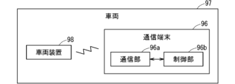
- FIG. 19 is a block diagram showing the configuration of a communication terminal 96 according to this modified example.
- a communication terminal 96 of FIG. 19 includes a communication unit 96a similar to the communication unit 91a and a control unit 96b similar to the control unit 91b, and is capable of wireless communication with a vehicle device 98 of a vehicle 97. ing.
- the communication terminal 96 for example, a portable terminal such as a mobile phone, a smart phone, or a tablet carried by the driver of the vehicle 97 is applied. According to the communication terminal 96 configured in this manner, it is possible to obtain the same effect as the update determination device 1 described in the first embodiment.
- 1 update determination device 11 acquisition unit, 12 control unit, 19 display unit.
Landscapes
- Engineering & Computer Science (AREA)
- Mechanical Engineering (AREA)
- Fittings On The Vehicle Exterior For Carrying Loads, And Devices For Holding Or Mounting Articles (AREA)
Priority Applications (2)
| Application Number | Priority Date | Filing Date | Title |
|---|---|---|---|
| PCT/JP2021/045230 WO2023105700A1 (ja) | 2021-12-09 | 2021-12-09 | 更新判定装置及び更新判定方法 |
| JP2023565793A JPWO2023105700A1 (https=) | 2021-12-09 | 2021-12-09 |
Applications Claiming Priority (1)
| Application Number | Priority Date | Filing Date | Title |
|---|---|---|---|
| PCT/JP2021/045230 WO2023105700A1 (ja) | 2021-12-09 | 2021-12-09 | 更新判定装置及び更新判定方法 |
Publications (1)
| Publication Number | Publication Date |
|---|---|
| WO2023105700A1 true WO2023105700A1 (ja) | 2023-06-15 |
Family
ID=86730009
Family Applications (1)
| Application Number | Title | Priority Date | Filing Date |
|---|---|---|---|
| PCT/JP2021/045230 Ceased WO2023105700A1 (ja) | 2021-12-09 | 2021-12-09 | 更新判定装置及び更新判定方法 |
Country Status (2)
| Country | Link |
|---|---|
| JP (1) | JPWO2023105700A1 (https=) |
| WO (1) | WO2023105700A1 (https=) |
Citations (5)
| Publication number | Priority date | Publication date | Assignee | Title |
|---|---|---|---|---|
| JP2011163979A (ja) * | 2010-02-10 | 2011-08-25 | Stanley Electric Co Ltd | 車載装置の受付制御装置および受付制御方法 |
| JP2014032119A (ja) * | 2012-08-03 | 2014-02-20 | Denso Corp | 操作制御装置、及び、操作制御プログラム |
| JP2017105224A (ja) * | 2015-12-07 | 2017-06-15 | 三菱自動車工業株式会社 | 車両制御装置 |
| JP2018069870A (ja) * | 2016-10-27 | 2018-05-10 | 住友電気工業株式会社 | 制御装置、制御方法及びコンピュータプログラム |
| JP2019144670A (ja) * | 2018-02-16 | 2019-08-29 | トヨタ自動車株式会社 | 車両制御装置、プログラムの更新確認方法および更新確認プログラム |
-
2021
- 2021-12-09 JP JP2023565793A patent/JPWO2023105700A1/ja active Pending
- 2021-12-09 WO PCT/JP2021/045230 patent/WO2023105700A1/ja not_active Ceased
Patent Citations (5)
| Publication number | Priority date | Publication date | Assignee | Title |
|---|---|---|---|---|
| JP2011163979A (ja) * | 2010-02-10 | 2011-08-25 | Stanley Electric Co Ltd | 車載装置の受付制御装置および受付制御方法 |
| JP2014032119A (ja) * | 2012-08-03 | 2014-02-20 | Denso Corp | 操作制御装置、及び、操作制御プログラム |
| JP2017105224A (ja) * | 2015-12-07 | 2017-06-15 | 三菱自動車工業株式会社 | 車両制御装置 |
| JP2018069870A (ja) * | 2016-10-27 | 2018-05-10 | 住友電気工業株式会社 | 制御装置、制御方法及びコンピュータプログラム |
| JP2019144670A (ja) * | 2018-02-16 | 2019-08-29 | トヨタ自動車株式会社 | 車両制御装置、プログラムの更新確認方法および更新確認プログラム |
Also Published As
| Publication number | Publication date |
|---|---|
| JPWO2023105700A1 (https=) | 2023-06-15 |
Similar Documents
| Publication | Publication Date | Title |
|---|---|---|
| CN111163968B (zh) | 交通工具中的显示系统 | |
| KR102770751B1 (ko) | 주행 가이드 정보를 제공하는 전자 장치 및 그 방법 | |
| KR102479540B1 (ko) | 주행 컨텍스트에 기반한 디스플레이 제어 방법 및 장치 | |
| KR102479072B1 (ko) | 탑승자 단말 및 디스트랙션 확인을 통한 컨텐츠 표시 방법 | |
| KR102303909B1 (ko) | 휴대 단말기 및 차량용 어플리케이션 제어 방법 | |
| KR101659027B1 (ko) | 이동 단말기 및 차량 제어 장치 | |
| US9613459B2 (en) | System and method for in-vehicle interaction | |
| CN105667421B (zh) | 包括眼跟踪装置的供车辆使用的系统和方法 | |
| US9904362B2 (en) | Systems and methods for use at a vehicle including an eye tracking device | |
| CN111452616B (zh) | 一种信息的显示控制方法、装置和车辆 | |
| JP7712774B2 (ja) | 注意に基づいた通知 | |
| US20150293745A1 (en) | Text-reading device and text-reading method | |
| CN105966405A (zh) | 驾驶员分心检测系统 | |
| US20200371733A1 (en) | Contextual and aware button-free screen articulation | |
| CN112513708B (zh) | 用于与车辆一起使用的设备和方法 | |
| EP4029716B1 (en) | Vehicle interactive system and method, storage medium, and vehicle | |
| CN109074151B (zh) | 信息显示方法和显示控制装置 | |
| JP2009015550A (ja) | 脇見検出装置および方法、並びに、プログラム | |
| US11429425B2 (en) | Electronic device and display and control method thereof to provide display based on operating system | |
| US9826206B2 (en) | Display control device, projection device, and non-transitory storage medium | |
| US20200159366A1 (en) | Operation support device and operation support method | |
| US20210073522A1 (en) | Occupant state determining device, warning output control device, and occupant state determining method | |
| US20170190254A1 (en) | Vehicular image display device and vehicular image display method | |
| JP7268526B2 (ja) | 車両用表示制御装置、及び車両用表示システム | |
| US20180246641A1 (en) | Triggering control of a zone using a zone image overlay on an in-vehicle display |
Legal Events
| Date | Code | Title | Description |
|---|---|---|---|
| 121 | Ep: the epo has been informed by wipo that ep was designated in this application |
Ref document number: 21967198 Country of ref document: EP Kind code of ref document: A1 |
|
| WWE | Wipo information: entry into national phase |
Ref document number: 2023565793 Country of ref document: JP |
|
| NENP | Non-entry into the national phase |
Ref country code: DE |
|
| 122 | Ep: pct application non-entry in european phase |
Ref document number: 21967198 Country of ref document: EP Kind code of ref document: A1 |