WO2023105700A1 - 更新判定装置及び更新判定方法 - Google Patents
更新判定装置及び更新判定方法 Download PDFInfo
- Publication number
- WO2023105700A1 WO2023105700A1 PCT/JP2021/045230 JP2021045230W WO2023105700A1 WO 2023105700 A1 WO2023105700 A1 WO 2023105700A1 JP 2021045230 W JP2021045230 W JP 2021045230W WO 2023105700 A1 WO2023105700 A1 WO 2023105700A1
- Authority
- WO
- WIPO (PCT)
- Prior art keywords
- update
- acquisition unit
- determined
- determination device
- control unit
- Prior art date
Links
- 238000000034 method Methods 0.000 title claims description 26
- 230000001815 facial effect Effects 0.000 claims description 2
- 238000010586 diagram Methods 0.000 description 24
- 230000008569 process Effects 0.000 description 20
- 238000004891 communication Methods 0.000 description 18
- 238000001514 detection method Methods 0.000 description 18
- 238000012545 processing Methods 0.000 description 17
- 230000006870 function Effects 0.000 description 13
- 230000004048 modification Effects 0.000 description 12
- 238000012986 modification Methods 0.000 description 12
- 230000006399 behavior Effects 0.000 description 10
- 210000000744 eyelid Anatomy 0.000 description 6
- 239000000470 constituent Substances 0.000 description 4
- 230000008859 change Effects 0.000 description 2
- 210000004087 cornea Anatomy 0.000 description 2
- 230000000694 effects Effects 0.000 description 2
- 238000012544 monitoring process Methods 0.000 description 2
- 230000007704 transition Effects 0.000 description 2
- 230000009471 action Effects 0.000 description 1
- 239000002131 composite material Substances 0.000 description 1
- 238000005516 engineering process Methods 0.000 description 1
- 210000000887 face Anatomy 0.000 description 1
- 239000004973 liquid crystal related substance Substances 0.000 description 1
- 230000003287 optical effect Effects 0.000 description 1
- 230000004043 responsiveness Effects 0.000 description 1
- 239000004065 semiconductor Substances 0.000 description 1
- 230000002123 temporal effect Effects 0.000 description 1
Images


Classifications
-
- B—PERFORMING OPERATIONS; TRANSPORTING
- B60—VEHICLES IN GENERAL
- B60R—VEHICLES, VEHICLE FITTINGS, OR VEHICLE PARTS, NOT OTHERWISE PROVIDED FOR
- B60R16/00—Electric or fluid circuits specially adapted for vehicles and not otherwise provided for; Arrangement of elements of electric or fluid circuits specially adapted for vehicles and not otherwise provided for
- B60R16/02—Electric or fluid circuits specially adapted for vehicles and not otherwise provided for; Arrangement of elements of electric or fluid circuits specially adapted for vehicles and not otherwise provided for electric constitutive elements
Definitions
- the present disclosure relates to an update determination device and an update determination method.
- a device has been proposed that updates the program of the equipment of the vehicle when the driver of the vehicle can manually drive the vehicle (for example, Patent Document 1).
- the program can be updated even when the ignition of the vehicle is not turned off, so it is possible to speed up the update and shorten the waiting time of the passenger for the update.
- the present disclosure has been made in view of the problems described above, and aims to provide a technology that can suppress careless driving by the driver.
- An update determination device includes an acquisition unit that acquires an image of the interior of a vehicle and an update program for updating the program of a device other than the device used for manual driving by the driver of the vehicle; Control for determining that the program can be updated by the update program acquired by the acquisition unit when it is determined that one or more fellow passengers are present in a seat other than the driver's seat of the vehicle based on the acquired image. and a part.
- the present disclosure when it is determined that one or more passengers are in a seat other than the driver's seat of the vehicle based on the acquired image, it is possible to update the program by the acquired update program. Since the determination is made, careless driving by the driver can be suppressed.
- FIG. 1 is a block diagram showing the configuration of an update determination device according to Embodiment 1;
- FIG. FIG. 9 is a block diagram showing the configuration of an update determination device according to Embodiment 2;
- FIG. 10 is a diagram showing an example of an image acquisition unit according to Embodiment 2;
- FIG. 10 is a diagram showing an example of an image according to Embodiment 2;
- FIG. 10 is a diagram showing an example of an image according to Embodiment 2;
- FIG. FIG. 11 is a diagram for explaining an operation example of a feature point detection unit according to Embodiment 2;
- FIG. 11 is a diagram for explaining an operation example of a feature point detection unit according to Embodiment 2;
- FIG. 11 is a diagram for explaining an operation example of a feature point detection unit according to Embodiment 2;
- FIG. 10 is a diagram showing an operation example of a feature point detection unit according to Embodiment 2;
- FIG. 11 is a diagram for explaining an operation example
- FIG. 11 is a diagram for explaining an operation example of a feature point detection unit according to Embodiment 2;
- FIG. 10 is a diagram for explaining an operation example of a face information analysis unit according to Embodiment 2;
- FIG. 10 is a diagram for explaining an operation example of a face information analysis unit according to Embodiment 2;
- FIG. 10 is a diagram for explaining an operation example of a face information analysis unit according to Embodiment 2;
- FIG. 10 is a diagram showing a display example of the update determination device according to Embodiment 2;
- 9 is a flow chart showing the operation of the update determination device according to Embodiment 2;
- FIG. 11 is a block diagram showing the configuration of an update determination device according to Modification 3; 14 is a flowchart showing the operation of an update determination device according to modification 3; FIG. 11 is a block diagram showing a hardware configuration of an update determination device according to another modified example; FIG. 11 is a block diagram showing a hardware configuration of an update determination device according to another modified example; FIG. 11 is a block diagram showing the configuration of a server according to another modified example; FIG. 11 is a block diagram showing the configuration of a communication terminal according to another modified example;
- FIG. 1 is a block diagram showing the configuration of an update determination device 1 according to the first embodiment.
- the update determination device 1 of FIG. 1 includes an acquisition unit 11 and a control unit 12 .
- the update determination device 1 may be applied to a DMS (Driver Monitoring System) or the like provided inside the vehicle, or may be provided outside the vehicle as described later.
- DMS Driver Monitoring System
- the acquisition unit 11 acquires an image of the interior of the vehicle.
- a camera and its interface device are used for the function of acquiring an image of the interior of the vehicle.
- the acquisition unit 11 also acquires an update program for updating the programs of the devices other than the devices used for manual driving by the driver of the vehicle.
- equipment used for manual driving by the driver of the vehicle may be referred to as "manual driving equipment”.
- Devices other than the devices for manual operation are, for example, devices mainly used for automatic driving, cameras, wireless communication devices, and the like.
- the update program acquisition function includes, for example, a wireless communication device that wirelessly communicates with a server, a device that reads the update program from a storage medium such as a USB memory storing the update program, and an interface device for them.
- the control unit 12 determines whether or not there is one or more fellow passengers in a seat other than the driver's seat of the vehicle.
- Seats other than the driver's seat of the vehicle are, for example, a passenger seat and a rear seat.
- the term "occupant" may be used when the driver and fellow passengers are not distinguished from each other.
- control unit 12 determines that the update program acquired by the acquisition unit 11 can be used to update the program. On the other hand, when it is determined that there is no fellow passenger, the control unit 12 determines that the program cannot be updated by the update program acquired by the acquisition unit 11 .
- control unit 12 may perform the update. Control may be performed to display the determination result as to whether it is possible or not.
- ⁇ Summary of Embodiment 1> According to the update determination device 1 according to the first embodiment as described above, when it is determined that one or more fellow passengers are present in a seat other than the driver's seat of the vehicle, the program is updated by the obtained update program. is possible. According to such a configuration, it is possible to allow a passenger other than the driver, that is, a fellow passenger, to determine whether updating by the update program is possible or not, so careless driving by the driver can be suppressed. In addition, since the program can be updated even when the ignition of the vehicle is not turned off, it is possible to speed up the update and shorten the waiting time of the passenger for the update.
- FIG. 2 is a block diagram showing the configuration of the update determination device 1 according to the second embodiment.
- constituent elements that are the same as or similar to the above-described constituent elements are denoted by the same or similar reference numerals, and different constituent elements will be mainly described.
- the update determination device 1 in FIG. 2 is connected to the device control unit 18 and the display unit 19 by wire or wirelessly so as to be communicable.
- the equipment control unit 18 controls the equipment of the vehicle based on a program stored in the memory of the vehicle.
- the device control unit 18 is, for example, an ECU (Electronic Control Unit).
- the display unit 19 performs various displays under the control of the update determination device 1.
- the display unit 19 is, for example, a display device such as a liquid crystal display device or a head-up display (HUD).
- the display unit 19 may be a display device integrated with the vehicle, or may be a display device brought into the vehicle.
- the update determination device 1 does not include the device control unit 18 and the display unit 19, but may include the device control unit 18 and the display unit 19.
- the update determination device 1 of FIG. 2 includes an image acquisition unit 11a, an update information acquisition unit 11b, an operation acquisition unit 11c, a feature point detection unit 12a, a face information analysis unit 12b, an update control unit 12c, and an HMI ( Human Machine Interface) control unit 12d.
- image acquisition unit 11a, the update information acquisition unit 11b, and the operation acquisition unit 11c are included in the concept of the acquisition unit 11 in FIG.
- the feature point detection unit 12a, the face information analysis unit 12b, the update control unit 12c, and the HMI control unit 12d are included in the concept of the control unit 12 in FIG.
- the image acquisition unit 11a acquires an image of the interior of the vehicle.
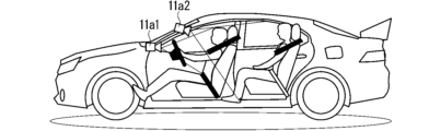
- the image acquisition unit 11a according to the second embodiment includes an instrument panel center camera 11a1 and an OHC (overhead console) camera 11a2 shown in FIG.
- the instrument panel center camera 11a1 is provided at the center of the instrument panel of the vehicle, and as shown in FIG. It is possible.
- the OHC camera 11a2 is provided on the OHC of the vehicle, and as shown in FIG. Shooting is possible.
- the image acquisition unit 11a may include either one of the instrument panel center camera 11a1 and the OHC camera 11a2, or may include cameras other than these. Further, the image acquisition unit 11a may change the brightness of the image to a predetermined brightness in consideration of the influence of the sunlight incident on the vehicle, or may acquire the image at a constant cycle.
- the update information acquisition unit 11b receives (that is, acquires) an update program from the server 61 for updating the programs of devices other than the devices for manual operation.
- the update information acquisition unit 11b is, for example, a wireless communication device.
- the server 61 includes a CPU (Central Processing Unit), memory, and an interface, all of which are not shown, and update programs are stored in the memory.
- the update determination device 1 determines whether the update program has been sent to the server 61. Recognize whether it exists or not. Then, when the update determination device 1 recognizes that the update program exists in the server 61 , the update information acquisition unit 11 b downloads the update program from the server 61 . Note that the update information acquisition unit 11b may be the target of the update program.
- the operation acquisition unit 11c acquires an update operation from the driver or fellow passenger.
- a touch panel may be used as the operation acquisition unit 11c, or an image recognition device capable of acquiring the gesture operation of the driver or the passenger based on the image acquired by the image acquisition unit 11a may be used. Alternatively, those interface devices may be used.
- the gesture operation may be an act of trying to update the program using the update program.
- the operation acquisition unit 11c is a touch panel, it may be included in the HMI control unit 12d.
- the feature point detection unit 12a detects the seat position of the vehicle based on the image acquired by the image acquisition unit 11a.
- the feature point detection unit 12a detects the area of the face image of the passenger sitting in each seat based on the image acquired by the image acquisition unit 11a. For example, when the image acquisition unit 11a acquires an image including a face image 21 as shown in FIG. 6, the feature point detection unit 12a detects a face image area 22 as shown in FIG.
- the feature point detection unit 12a detects feature points 23 for facial parts such as the eyes, nose, and mouth from the face image area 22. For example, when a face image area 22 as shown in FIG. 7 is detected, the feature point detection unit 12a detects a plurality of feature points 23 as shown in FIG. 6 to 8, the face image area 22 and the feature points 23 are detected for the driver who operates the steering wheel 20, but the face image area 22 and the feature points 23 are similarly detected for the fellow passenger. .
- the face information analysis section 12b determines at least one of the face direction, the line of sight direction, and the degree of eye opening/closing. Detect as face information. In the second embodiment, face information is detected for each passenger.
- the plurality of feature points 23 are inner corners 23a and 23e, outer corners 23b and 23f, upper eyelids 23c and 23g, lower eyelids 23d and 23h, nasal root 23i, and nasal tip 23j. , the wings of the nose 23k, the corners of the mouth 23l, 23m, and the center of the lips 23n.
- the feature points 23 are not limited to these, and may include, for example, the cornea, the back of the nose, the upper lip, the lower lip, and the like.
- the face information analysis unit 12b detects left as the face orientation of the face image 21 when the tip of the nose 23j is positioned to the left of the outer corner of the eye 23b.
- the face information analysis unit 12b detects that the face of the face image 21 faces upward, and the tip of the nose 23j If the face is positioned below the line, the downward direction is detected as the face orientation of the face image 21 .
- the face information analysis unit 12b detects that the face of the face image 21 is facing right when the tip of the nose 23j is located on the right side of the corner of the eye 23f.
- the face information analysis unit 12b detects the degree of eye openness based on the distance between the upper eyelids 23c, 23g and the lower eyelids 23d, 23h.
- the face information analysis unit 12b detects the direction of the line of sight based on the positional relationship among the cornea, inner corners 23a and 23e, outer corners 23b and 23f, upper eyelids 23c and 23g, and lower eyelids 23d and 23h. do.
- the update control unit 12c in FIG. 2 determines whether or not the program update permission condition is satisfied based on the acquisition status of the update information acquisition unit 11b and the face information detected by the face information analysis unit 12b.
- the program update permission status according to the second embodiment indicates that the update program has been acquired (that is, the update program has been stored in the memory of the update determination device 1), and the driver's seat of the vehicle This is a situation in which one or more fellow passengers are in seats other than the above.
- the update control unit 12c determines that the program can be updated by the update program acquired by the update information acquisition unit 11b. On the other hand, when it is determined that the program update permission status is not satisfied, the update control unit 12c determines that the program cannot be updated by the update program acquired by the update information acquisition unit 11b.
- the update control unit 12c also determines whether or not the fellow passengers are only sleeping occupants based on the face information detected by the face information analysis unit 12b.
- the update control unit 12c determines whether or not the fellow passenger is asleep based on, for example, the degree of eye opening and closing of the fellow passenger, the direction of the line of sight, and their temporal change (for example, PERCLOS). Note that the update control unit 12c determines that the fellow passenger is asleep not only when the fellow passenger is in a sleeping state but also when the fellow passenger is in a state between an awake state and a sleeping state. good too. Further, whether or not the fellow passenger is sleeping may be determined based on a radio wave sensor.
- the update control unit 12c determines that the update is impossible if one or more fellow passengers are not in an awake state even if the program update permission status is satisfied. In other words, when it is determined that there is a fellow passenger and that the fellow passengers are only sleeping occupants, the update control unit 12c determines that the update is impossible.
- the HMI control unit 12d controls the display unit 19 to display that the update is possible. Further, when the update control unit 12c determines that the update is impossible, the HMI control unit 12d controls the display unit 19 to display that the update is impossible.
- FIG. 12 is a diagram showing a display example of the display unit 19 when the update control unit 12c determines that the update is possible.
- the display unit 19 in FIG. 12 is a display device having a touch panel, which is the operation acquisition unit 11c, on the screen, and displays text indicating that updating is possible and buttons 28a, 28b, and 28c.
- the button 28a is a button for starting to update the programs of the equipment other than the manual operation equipment using the update program.
- the button 28b is a button for displaying an update schedule such as a predicted required time for updating.
- the button 28c is a button for displaying details of the update content.
- the update control unit 12c determines that the operation acquired by the operation acquisition unit 11c after the display unit 19 displays that the update is possible is an operation by the driver. , it is determined that updating is impossible. On the other hand, if the update control unit 12c determines that the operation acquired by the operation acquisition unit 11c after the display unit 19 displays that the update is possible is an operation from the fellow passenger, the update is not performed. The determination that it is possible is maintained.
- the update control unit 12c determines that the update is possible without determining that the update is impossible until the end of the series of determination processing, the update control unit 12c selects the manual The update programs are used to update the programs of the devices other than the driving devices.
- FIG. 13 is a flow chart showing the operation of the update determination device 1 according to the second embodiment. The operation of FIG. 13 begins when the vehicle ignition is turned on.
- step S1 the update control unit 12c determines whether the update information acquisition unit 11b has acquired the update program from the server 61. If it is determined that the update information acquisition unit 11b has acquired the update program, the process proceeds to step S2, and if it is determined that the update information acquisition unit 11b has not acquired the update program, the process of step S1 is performed again. done.
- step S2 the update control unit 12c determines whether or not the ignition of the vehicle is kept on. If it is determined that the ignition is maintained on, the process proceeds to step S3, and if it is not determined that the ignition is maintained on, the process proceeds to step S10.
- the image acquisition unit 11a acquires an image of the interior of the vehicle.
- step S4 the update control unit 12c determines whether or not there is one or more fellow passengers in a seat other than the driver's seat of the vehicle based on the face information detected from the image acquired in step S3. If it is determined that there is a fellow passenger, the process proceeds to step S5, and if it is not determined that there is a fellow passenger, the process returns to step S2. Note that the process may proceed to step S10 when the transition from step S4 to step S2 is repeated a certain number of times or more.
- the image acquisition unit 11a acquires an image of the interior of the vehicle.
- step S6 the update control unit 12c determines whether the fellow passengers are only sleeping occupants based on the face information detected from the image acquired in step S5. When it is determined that the fellow passengers are only sleeping occupants, the process returns to step S5, and when it is not determined that the fellow passengers are only sleeping occupants, the process proceeds to step S7. Note that the process may proceed to step S10 when the transition from step S6 to step S5 is repeated a certain number of times or more. Further, the process of step S5 may be omitted by using the face information detected from the image acquired at step S2 instead of the face information detected from the image acquired at step S5.
- step S7 the HMI control unit 12d controls the display unit 19 to display that updating is possible.
- the display unit 19 performs display such as the display example of FIG. 12 .
- step S8 the update control unit 12c determines whether or not the operation acquired by the operation acquisition unit 11c is the operation by the driver after the display in step S7. When it is determined that the operation acquired by the operation acquiring unit 11c is the operation by the driver, the process proceeds to step S10, and it is determined that the operation acquired by the operation acquiring unit 11c is the operation by the passenger. If so, the process proceeds to step S9.
- step S9 the update control unit 12c updates the programs of the devices other than the devices for manual operation using the update program.
- the HMI control unit 12d controls the display unit 19 to display that updating is impossible.
- the update determination device 1 it is determined that the operation acquired by the operation acquisition unit 11c after the display unit 19 displays that the update is possible is the operation by the driver. If so, it is determined that the update is impossible. According to such a configuration, careless driving by the driver can be suppressed.
- the feature point detection unit 12a may detect not only the face image area 22 and the feature points, but also the presence or absence of a child seat in the seat, or may detect the physique and skeleton of the occupant. may be detected.
- the update control unit 12c may determine whether or not the fellow passengers are the only passengers seated in the child seat based on the detection result of the feature point detection unit 12a. This determination may be made, for example, when the process of step S6 in FIG. 13 is performed. Then, even if it is determined that there is a fellow passenger, the update control unit 12c determines that the update cannot be performed if it is determined that the fellow passenger is the only passenger seated in the child seat. You can judge. According to such a configuration, updating can be suppressed when there is no suitable fellow passenger.
- the face information analysis unit 12b may detect the attributes of the occupant whose face image 21 is detected based on the positional relationship of the plurality of feature points 23 detected by the feature point detection unit 12a. An example of such attribute detection by the face information analysis unit 12b will be described below.
- attributes eg, personal information, age, gender, etc.
- stored feature points For example, attributes (eg, personal information, age, gender, etc.) are associated in advance with the positional relationships of the plurality of feature points 23 and stored in the memory of the update determination device 1 .
- the feature points 23 detected by the feature point detection unit 12a may be referred to as “detected feature points”, and the feature points 23 stored in the memory may be referred to as “stored feature points”.
- the face information analysis unit 12b determines whether or not the positional relationship between the plurality of detected feature points substantially matches the positional relationship between the plurality of stored feature points. When it is determined that the positional relationship of the plurality of detected feature points substantially matches the positional relationship of the plurality of stored feature points, the face information analysis unit 12b stores the attributes of the occupant having the plurality of detected feature points in the memory. are detected as attributes associated with the positional relationship of a plurality of stored feature points.
- the update control unit 12c determines whether or not the fellow passengers are only passengers other than predetermined passengers based on the personal information. may This determination may be made, for example, when the process of step S6 in FIG. 13 is performed. Then, even if it is determined that there is a fellow passenger, the update control unit 12c cannot perform the update if it is determined that the fellow passenger is only a passenger other than a predetermined passenger. can be determined. According to such a configuration, updating can be suppressed when there is no suitable fellow passenger.
- the update control unit 12c determines whether or not the fellow passengers are only passengers younger than a predetermined age based on the age. good. This determination may be made, for example, when the process of step S6 in FIG. 13 is performed. Then, even if it is determined that there is a fellow passenger, the update control unit 12c cannot update if it is determined that the fellow passengers are only passengers younger than the predetermined age. can be determined. According to such a configuration, updating can be suppressed when there is no suitable fellow passenger.
- FIG. 14 is a block diagram showing the configuration of the update determination device 1 according to Modification 3. As shown in FIG. The configuration of the update determination device 1 of FIG. 14 is the same as the configuration of the update determination device 1 of FIG. 2 with a behavior information acquisition unit 11d added.
- the behavior information acquisition unit 11d acquires vehicle behavior information from which the speed of the vehicle can be acquired or calculated.
- the behavior information acquisition unit 11d is included in the concept of the acquisition unit 11 in FIG.
- the update control unit 12c determines whether the vehicle is running based on the behavior information acquired by the behavior information acquisition unit 11d. Then, only when it is determined that the vehicle is running, the update control section 12c determines whether or not the program can be updated by the update program acquired by the update information acquisition section 11b.
- FIG. 15 is a flow chart showing the operation of the update determination device 1 according to the third modification. Since the operation of FIG. 15 is the same as the operation of FIG. 13 with steps S21 and S22 added, the processing of steps S21 and S22 will be mainly described below.
- step S21 the behavior information acquisition unit 11d acquires vehicle behavior information.
- the update control unit 12c determines whether the vehicle is running based on the behavior information acquired by the behavior information acquisition unit 11d. If it is determined that the vehicle is running, the process proceeds to step S3, and if it is not determined that the vehicle is running, the process returns to step S2.
- the program is not updated when the vehicle is not running, that is, when the vehicle is stopped. Therefore, it is possible to reduce the load due to the updating process while the vehicle is stopped, so it is possible to improve the responsiveness of the equipment of the vehicle to the operation performed while the vehicle is stopped at a red light of a traffic light or the like.
- the update control unit 12c updates the display unit 19 based on the face image of the driver among the images acquired by the image acquisition unit 11a after the display unit 19 displays that the update is possible. It may be determined whether or not the display of is visually recognized. This determination may be made, for example, when the process of step S8 in FIG. 13 is performed. Then, when it is determined that the driver is viewing the display on the display unit 19, the update control unit 12c may determine that the update is impossible. According to such a configuration, careless driving by the driver can be suppressed.
- the acquisition unit 11 and the control unit 12 shown in FIG. 1 described above are hereinafter referred to as “acquisition unit 11 and the like”.
- the acquisition unit 11 and the like are realized by the processing circuit 81 shown in FIG. That is, the processing circuit 81 includes an acquisition unit 11 that acquires an image of the interior of the vehicle and an update program for updating the programs of the devices other than the devices used for manual operation by the driver of the vehicle; and a control unit 12 for determining that the program can be updated by the acquired update program when it is determined that one or more fellow passengers are present in a seat other than the driver's seat of the vehicle based on the above.
- Dedicated hardware may be applied to the processing circuit 81, or a processor that executes a program stored in a memory may be applied.
- Processors include, for example, central processing units, processing units, arithmetic units, microprocessors, microcomputers, and DSPs (Digital Signal Processors).
- the processing circuit 81 When the processing circuit 81 is a processor, the functions of the acquisition unit 11 and the like are realized by combining with software and the like.
- Software and the like correspond to, for example, software, firmware, or software and firmware.
- Software or the like is written as a program and stored in memory.
- a processor 82 applied to a processing circuit 81 reads out and executes a program stored in a memory 83 to implement the functions of each unit. That is, when the update determination device 1 is executed by the processing circuit 81, the image of the interior of the vehicle and the update program for updating the programs of the devices other than the devices used for manual driving by the driver of the vehicle.
- the program can be updated by the acquired update program when it is determined that at least one passenger is in a seat other than the driver's seat of the vehicle based on the acquiring step and the acquired image. and a memory 83 for storing the resulting program to be executed.
- this program causes a computer to execute the procedures and methods of the acquisition unit 11 and the like.
- the memory 83 is, for example, a non-volatile or Volatile semiconductor memory, HDD (Hard Disk Drive), magnetic disk, flexible disk, optical disk, compact disk, mini disk, DVD (Digital Versatile Disc), their drive devices, or any storage media that will be used in the future. may
- each function of the acquisition unit 11 and the like is realized by either hardware or software has been described above.
- the configuration is not limited to this, and a configuration in which a part of the acquisition unit 11 and the like is realized by dedicated hardware and another part is realized by software or the like may be employed.
- the function of the acquisition unit 11 is realized by a processing circuit 81 as dedicated hardware, an interface, a receiver, and the like. It is possible to realize the function by executing it.
- the processing circuit 81 can implement each of the functions described above by means of hardware, software, etc., or a combination thereof.
- the update determination device described above includes a vehicle device such as a navigation device and a DMS (Driver Monitoring System), a communication terminal including a mobile terminal such as a mobile phone, a smartphone, and a tablet, and at least one of the vehicle device and the communication terminal.
- vehicle device such as a navigation device and a DMS (Driver Monitoring System)
- communication terminal including a mobile terminal such as a mobile phone, a smartphone, and a tablet, and at least one of the vehicle device and the communication terminal.
- the present invention can also be applied to an update determination system constructed as a system by appropriately combining the functions of applications installed together with a server.
- each function or each component of the update determination device described above may be distributed to each device that constructs the system, or may be centrally disposed in any one of the devices. .
- FIG. 18 is a block diagram showing the configuration of the server 91 according to this modified example.
- a server 91 in FIG. 18 includes a communication unit 91a and a control unit 91b, and is capable of wirelessly communicating with a vehicle device 93 of a vehicle 92.
- the server 91 shown in FIG. 18 is a block diagram showing the configuration of the server 91 according to this modified example.
- a server 91 in FIG. 18 includes a communication unit 91a and a control unit 91b, and is capable of wirelessly communicating with a vehicle device 93 of a vehicle 92.
- the communication unit 91a which is an acquisition unit, receives the image of the interior of the vehicle 92 acquired by the vehicle device 93 by wirelessly communicating with the vehicle device 93, and wirelessly communicates with another server to obtain the update program. receive.
- the control unit 91b has the same function as the control unit 12 in FIG. That is, when it is determined that one or more fellow passengers are in the seats other than the driver's seat of the vehicle 92 based on the image received by the communication unit 91a, the control unit 91b updates the information received by the communication unit 91a. It is determined that the program can be updated by the program. Then, the communication unit 91 a transmits the determination result of the control unit 91 b to the vehicle device 93 . According to the server 91 configured in this way, it is possible to obtain the same effect as the update determination device 1 described in the first embodiment.
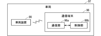
- FIG. 19 is a block diagram showing the configuration of a communication terminal 96 according to this modified example.
- a communication terminal 96 of FIG. 19 includes a communication unit 96a similar to the communication unit 91a and a control unit 96b similar to the control unit 91b, and is capable of wireless communication with a vehicle device 98 of a vehicle 97. ing.
- the communication terminal 96 for example, a portable terminal such as a mobile phone, a smart phone, or a tablet carried by the driver of the vehicle 97 is applied. According to the communication terminal 96 configured in this manner, it is possible to obtain the same effect as the update determination device 1 described in the first embodiment.
- 1 update determination device 11 acquisition unit, 12 control unit, 19 display unit.
Landscapes
- Engineering & Computer Science (AREA)
- Mechanical Engineering (AREA)
- Fittings On The Vehicle Exterior For Carrying Loads, And Devices For Holding Or Mounting Articles (AREA)
Abstract
運転者の不注意運転を抑制可能な技術を提供することを目的とする。更新判定装置は、車両の室内の画像と、車両の運転者の手動運転に用いられる機器以外の機器のプログラムを更新するための更新プログラムとを取得する取得部と、取得部で取得された画像に基づいて、車両の運転席以外の座席に1以上の同乗者がいると判定された場合に、取得部で取得された更新プログラムによるプログラムの更新が可能であると判定する制御部とを備える。
Description
本開示は、更新判定装置及び更新判定方法に関する。
車両の運転者が手動運転可能である場合に、車両の機器のプログラムを更新する装置が提案されている(例えば特許文献1)。このような構成によれば、車両のイグニションがオフでない場合でもプログラムの更新が可能となるので、更新の早期化と、更新に対する乗員の待ち時間の短縮化とが可能となる。
自動車基準調和世界フォーラム(WP29)のSU(Software Update)法では、乗員に更新内容及び更新の予測所要時間を明示した上で、乗員から更新可の承認が得られた場合に、プログラムの更新を行うことが規定されている。しかしながら、車両の運転者が手動運転を行いながら、更新内容を理解して更新可と判断することは困難であり、不注意運転の原因となるという問題があった。
そこで、本開示は、上記のような問題点に鑑みてなされたものであり、運転者の不注意運転を抑制可能な技術を提供することを目的とする。
本開示に係る更新判定装置は、車両の室内の画像と、車両の運転者の手動運転に用いられる機器以外の機器のプログラムを更新するための更新プログラムとを取得する取得部と、取得部で取得された画像に基づいて、車両の運転席以外の座席に1以上の同乗者がいると判定された場合に、取得部で取得された更新プログラムによるプログラムの更新が可能であると判定する制御部とを備える。
本開示によれば、取得された画像に基づいて、車両の運転席以外の座席に1以上の同乗者がいると判定された場合に、取得された更新プログラムによるプログラムの更新が可能であると判定するので、運転者の不注意運転を抑制することができる。
本開示の目的、特徴、局面及び利点は、以下の詳細な説明と添付図面とによって、より明白となる。
<実施の形態1>
図1は、本実施の形態1に係る更新判定装置1の構成を示すブロック図である。図1の更新判定装置1は、取得部11と、制御部12とを備える。更新判定装置1は、車両内に設けられたDMS(Driver Monitoring System)などに適用されてもよいし、後述するように車両外に設けられてもよい。
図1は、本実施の形態1に係る更新判定装置1の構成を示すブロック図である。図1の更新判定装置1は、取得部11と、制御部12とを備える。更新判定装置1は、車両内に設けられたDMS(Driver Monitoring System)などに適用されてもよいし、後述するように車両外に設けられてもよい。
取得部11は、車両の室内の画像を取得する。車両の室内の画像を取得する機能には、例えばカメラ、及び、そのインターフェース装置などが用いられる。
また取得部11は、車両の運転者の手動運転に用いられる機器以外の機器のプログラムを更新するための更新プログラムを取得する。以下の説明では、車両の運転者の手動運転に用いられる機器を「手動運転用機器」と記すこともある。手動運転用機器以外の機器は、例えば、自動運転に主に用いられる機器、カメラ及び無線通信装置などである。更新プログラムを取得する機能には、例えばサーバと無線通信を行う無線通信装置、更新プログラムが記憶されたUSBメモリなどの記憶媒体から更新プログラムを読み取る装置、及び、それらのインターフェース装置などが用いられる。
制御部12は、取得部11で取得された画像に基づいて、車両の運転席以外の座席に1以上の同乗者がいるか否かを判定する。車両の運転席以外の座席は、例えば助手席及び後部座席などである。なお、以下の説明では、運転者及び同乗者を区別しない場合には「乗員」と記すこともある。
制御部12は、同乗者がいると判定された場合に、取得部11で取得された更新プログラムによるプログラムの更新が可能であると判定する。一方、制御部12は、同乗者がいないと判定された場合に、取得部11で取得された更新プログラムによるプログラムの更新が不可能であると判定する。
実施の形態2で説明するように、制御部12は、取得部11で取得された更新プログラムによるプログラムの更新が可能であると判定された場合に、当該更新を行ってもよいし、更新が可能か不可能かの判定結果を表示する制御を行ってもよい。
<実施の形態1のまとめ>
以上のような本実施の形態1に係る更新判定装置1によれば、車両の運転席以外の座席に1以上の同乗者がいると判定された場合に、取得された更新プログラムによるプログラムの更新が可能であると判定する。このような構成によれば、運転者以外の乗員、つまり同乗者に、更新プログラムによる更新が可能か不可能かを判断させることができるので、運転者の不注意運転を抑制することができる。また、車両のイグニションがオフでない場合でもプログラムの更新が可能となるので、更新の早期化と、更新に対する乗員の待ち時間の短縮化とが可能となる。
以上のような本実施の形態1に係る更新判定装置1によれば、車両の運転席以外の座席に1以上の同乗者がいると判定された場合に、取得された更新プログラムによるプログラムの更新が可能であると判定する。このような構成によれば、運転者以外の乗員、つまり同乗者に、更新プログラムによる更新が可能か不可能かを判断させることができるので、運転者の不注意運転を抑制することができる。また、車両のイグニションがオフでない場合でもプログラムの更新が可能となるので、更新の早期化と、更新に対する乗員の待ち時間の短縮化とが可能となる。
<実施の形態2>
図2は、本実施の形態2に係る更新判定装置1の構成を示すブロック図である。以下、本実施の形態2に係る構成要素のうち、上述の構成要素と同じまたは類似する構成要素については同じまたは類似する参照符号を付し、異なる構成要素について主に説明する。
図2は、本実施の形態2に係る更新判定装置1の構成を示すブロック図である。以下、本実施の形態2に係る構成要素のうち、上述の構成要素と同じまたは類似する構成要素については同じまたは類似する参照符号を付し、異なる構成要素について主に説明する。
図2の更新判定装置1は、機器制御部18及び表示部19と通信可能に有線または無線で接続されている。
機器制御部18は、車両のメモリなどに記憶されたプログラムに基づいて、車両の機器を制御する。機器制御部18は、例えばECU(Electronic Control Unit)などである。
表示部19は、更新判定装置1の制御により各種表示を行う。表示部19は、例えば液晶表示装置及びヘッドアップディスプレイ(HUD)などの表示装置である。表示部19は、車両に一体化された表示装置であってもよいし、車両に持ち込まれた表示装置であってもよい。
なお図2の例では、更新判定装置1は、機器制御部18及び表示部19を備えないが、機器制御部18及び表示部19を備えてもよい。
図2の更新判定装置1は、画像取得部11aと、更新情報取得部11bと、操作取得部11cと、特徴点検出部12aと、顔情報分析部12bと、更新制御部12cと、HMI(Human Machine Interface)制御部12dとを備える。なお、画像取得部11a、更新情報取得部11b、及び、操作取得部11cは、図1の取得部11の概念に含まれる。特徴点検出部12a、顔情報分析部12b、更新制御部12c、及び、HMI制御部12dは、図1の制御部12の概念に含まれる。
画像取得部11aは、車両の室内の画像を取得する。本実施の形態2に係る画像取得部11aは、図3のインパネセンターカメラ11a1及びOHC(overhead console)カメラ11a2を含む。インパネセンターカメラ11a1は、車両のインストルメントパネルの中央に設けられており、図4に示すように、運転席の運転者、及び、助手席の同乗者の画像を含む車両の室内の画像を撮影可能である。OHCカメラ11a2は、車両のOHCに設けられており、図5に示すように、運転席の運転者、助手席の同乗者、及び、後部座席の同乗者の画像を含む車両の室内の画像を撮影可能である。
なお、画像取得部11aは、インパネセンターカメラ11a1及びOHCカメラ11a2のいずれか1つを含んでもよいし、これら以外のカメラを含んでもよい。また、画像取得部11aは、車両に入射する太陽光などの影響を考慮して、画像の輝度を予め定められた輝度に変更してもよいし、画像を一定周期で取得してもよい。
更新情報取得部11bは、サーバ61から、手動運転用機器以外の機器のプログラムを更新するための更新プログラムを受信(つまり取得)する。更新情報取得部11bは、例えば無線通信装置である。
サーバ61は、いずれも図示しないCPU(Central Processing Unit)、メモリ、及び、インターフェースを備え、メモリには更新プログラムが記憶されている。サーバ61が更新プログラムの存在を更新情報取得部11bに通知するか、更新情報取得部11bが一定の時間間隔で更新プログラムの有無を確認するかによって、更新判定装置1はサーバ61に更新プログラムが存在するか否かを認識する。そして、更新判定装置1がサーバ61に更新プログラムが存在すると認識した場合に、更新情報取得部11bはサーバ61から更新プログラムをダウンロードする。なお、更新情報取得部11bが更新プログラムの対象であってもよい。
操作取得部11cは、運転者または同乗者からの更新を行うための操作を取得する。操作取得部11cには、例えば、タッチパネルが用いられてもよいし、画像取得部11aで取得された画像に基づいて運転者または同乗者のジェスチャ操作を取得可能な画像認識装置が用いられてもよいし、それらのインターフェース装置が用いられてもよい。ジェスチャ操作は、更新プログラムによるプログラムの更新を行おうとする行為であってもよい。また、操作取得部11cがタッチパネルである場合には、HMI制御部12dに含まれてもよい。
特徴点検出部12aは、画像取得部11aで取得された画像に基づいて、車両の座席位置を検出する。特徴点検出部12aは、画像取得部11aで取得された画像に基づいて、各座席に着座している乗員の顔画像の領域を検出する。例えば、画像取得部11aで図6のような顔画像21を含む画像を取得した場合、特徴点検出部12aは、図7のような顔画像領域22を検出する。
特徴点検出部12aは、顔画像領域22から顔の目、鼻、口などの顔のパーツについて特徴点23を検出する。例えば、図7のような顔画像領域22が検出された場合、特徴点検出部12aは、図8のような複数の特徴点23を検出する。なお、図6~図8では、ステアリング20を操作する運転者について顔画像領域22及び特徴点23が検出されているが、同乗者についても同様に顔画像領域22及び特徴点23が検出される。
顔情報分析部12bは、特徴点検出部12aで検出された複数の特徴点23の位置関係に基づいて、顔の向き、視線の向き、及び、目の開閉度の少なくともいずれか1つを、顔情報として検出する。本実施の形態2では、顔情報は各乗員について検出される。
図9~図11は、顔情報分析部12bによる顔情報の検出を説明するための図である。図9~図11の例では、複数の特徴点23は、目頭23a,23eと、目尻23b,23fと、上瞼23c,23gと、下瞼23d,23hと、鼻根23iと、鼻尖23jと、鼻翼23kと、口角23l,23mと、唇の中央23nとを含む。なお、特徴点23は、これらに限ったものではなく、例えば、角膜、鼻背、上唇、下唇などを含んでもよい。
例えば、顔情報分析部12bは、図9に示すように、鼻尖23jが目尻23bから左側に位置する場合には、顔画像21の顔の向きとして左向きを検出する。顔情報分析部12bは、図10に示すように、鼻尖23jが顔を上下に区分する線よりも上側に位置する場合には、顔画像21の顔の向きとして上向きを検出し、鼻尖23jが当該線よりも下側に位置する場合には、顔画像21の顔の向きとして下向きを検出する。顔情報分析部12bは、図11に示すように、鼻尖23jが目尻23fから右側に位置する場合には、顔画像21の顔の向きとして右向きを検出する。
また例えば、顔情報分析部12bは、上瞼23c,23gと、下瞼23d,23hとの間の距離に基づいて、目の開閉度を検出する。
また例えば、顔情報分析部12bは、角膜と、目頭23a,23eと、目尻23b,23fと、上瞼23c,23gと、下瞼23d,23hとの位置関係に基づいて、視線の向きを検出する。
図2の更新制御部12cは、更新情報取得部11bの取得状況と顔情報分析部12bで検出された顔情報とに基づいて、プログラム更新許可状況が満たされているか否かを判定する。原則として、本実施の形態2に係るプログラム更新許可状況は、更新プログラムの取得が済んでおり(つまり更新判定装置1のメモリへの更新プログラムの格納が済んでおり)、かつ、車両の運転席以外の座席に1以上の同乗者がいる状況である。
更新制御部12cは、プログラム更新許可状況が満たされていると判定された場合に、更新情報取得部11bで取得された更新プログラムによるプログラムの更新が可能であると判定する。一方、更新制御部12cは、プログラム更新許可状況が満たされていないと判定された場合に、更新情報取得部11bで取得された更新プログラムによるプログラムの更新が不可能であると判定する。
また更新制御部12cは、顔情報分析部12bで検出された顔情報に基づいて、同乗者が睡眠中の乗員のみであるか否かを判定する。更新制御部12cは、例えば、同乗者の目の開閉度と、視線の向きと、それらの時間変化(例えばPERCLOS)とに基づいて、同乗者が睡眠中であるか否かを判定する。なお、同乗者が睡眠状態である場合だけでなく、同乗者が覚醒状態と睡眠状態との間の状態である場合も、更新制御部12cは、当該同乗者が睡眠中であると判定してもよい。また、同乗者が睡眠中であるか否かを判定は、電波センサに基づいて行われてもよい。
更新制御部12cは、プログラム更新許可状況が満たされている場合であっても、1以上の同乗者が覚醒状態でない場合には、上記更新が不可能であると判定する。つまり、更新制御部12cは、同乗者がいると判定され、かつ、同乗者が睡眠中の乗員のみであると判定された場合には、上記更新が不可能であると判定する。
HMI制御部12dは、更新制御部12cで更新が可能であると判定された場合に、更新が可能であることを表示部19に表示させる制御を行う。また、HMI制御部12dは、更新制御部12cで更新が不可能であると判定された場合に、更新が不可能であることを表示部19に表示させる制御を行う。
図12は、更新制御部12cで更新が可能であると判定された場合の表示部19の表示例を示す図である。図12の表示部19は、操作取得部11cであるタッチパネルが画面に設けられた表示装置であり、更新が可能であることを示す文章と、ボタン28a,28b,28cとを表示する。ボタン28aは、更新プログラムによって、手動運転用機器以外の機器のプログラムの更新を開始するためのボタンである。ボタン28bは、更新の予測所要時間などの更新スケージュールを表示するためのボタンである。ボタン28cは、更新内容の詳細を表示するためのボタンである。
本実施の形態2では、更新制御部12cは、表示部19で更新が可能であることが表示された後に操作取得部11cで取得された操作が運転者からの操作であると判定された場合に、更新が不可能であると判定する。一方、更新制御部12cは、表示部19で更新が可能であることが表示された後に操作取得部11cで取得された操作が同乗者からの操作であると判定された場合には、更新が可能であるという判定が維持される。
そして、更新制御部12cは、一連の判定処理の最後まで更新が不可能であると判定されずに更新が可能であると判定された場合に、機器制御部18で用いられるプログラムのうち、手動運転用機器以外の機器のプログラムの更新を、更新プログラムによって行う。
<動作>
図13は、本実施の形態2に係る更新判定装置1の動作を示すフローチャートである。図13の動作は、車両のイグニションがオンになった場合に開始される。
図13は、本実施の形態2に係る更新判定装置1の動作を示すフローチャートである。図13の動作は、車両のイグニションがオンになった場合に開始される。
ステップS1にて、更新制御部12cは、更新情報取得部11bがサーバ61から更新プログラムを取得したか否かを判定する。更新情報取得部11bが更新プログラムを取得したと判定された場合には処理がステップS2に進み、更新情報取得部11bが更新プログラムを取得したと判定されなかった場合にはステップS1の処理が再度行われる。
ステップS2にて、更新制御部12cは、車両のイグニションのオンが維持されているか否かを判定する。イグニションのオンが維持されていると判定された場合には処理がステップS3に進み、イグニションのオンが維持されていると判定されなかった場合には処理がステップS10に進む。
ステップS3にて、画像取得部11aは、車両の室内の画像を取得する。
ステップS4にて、更新制御部12cは、ステップS3で取得された画像から検出された顔情報に基づいて、車両の運転席以外の座席に1以上の同乗者がいるか否かを判定する。同乗者がいると判定された場合には処理がステップS5に進み、同乗者がいると判定されなかった場合には処理がステップS2に戻る。なお、ステップS4からステップS2への遷移が一定回数以上繰り返された場合に、処理がステップS10に進んでもよい。
ステップS5にて、画像取得部11aは、車両の室内の画像を取得する。
ステップS6にて、更新制御部12cは、ステップS5で取得された画像から検出された顔情報に基づいて、同乗者が睡眠中の乗員のみであるか否かを判定する。同乗者が睡眠中の乗員のみであると判定された場合には処理がステップS5に戻り、同乗者が睡眠中の乗員のみであると判定されなかった場合には処理がステップS7に進む。なお、ステップS6からステップS5への遷移が一定回数以上繰り返された場合に、処理がステップS10に進んでもよい。また、ステップS5で取得された画像から検出された顔情報の代わりに、ステップS2で取得された画像から検出された顔情報を用いることによって、ステップS5の処理が省略されてもよい。
ステップS7にて、HMI制御部12dは、更新が可能であることを表示部19に表示させる制御を行う。これにより、表示部19は、図12の表示例のような表示を行う。
ステップS8にて、更新制御部12cは、ステップS7の表示後に、操作取得部11cで取得された操作が運転者からの操作であるか否かを判定する。操作取得部11cで取得された操作が運転者からの操作であると判定された場合には処理がステップS10に進み、操作取得部11cで取得された操作が同乗者からの操作であると判定された場合には処理がステップS9に進む。
ステップS9にて、更新制御部12cは、手動運転用機器以外の機器のプログラムの更新を、更新プログラムによって行う。
ステップS10に進んだ場合には、HMI制御部12dは、更新が不可能であることを表示部19に表示させる制御を行う。
<実施の形態2のまとめ>
以上のような本実施の形態2に係る更新判定装置1によれば、同乗者がいると判定され、かつ、同乗者が睡眠中の乗員のみであると判定された場合には、更新が不可能であると判定する。このような構成によれば、適切な同乗者がいない場合には、更新を抑制することができる。
以上のような本実施の形態2に係る更新判定装置1によれば、同乗者がいると判定され、かつ、同乗者が睡眠中の乗員のみであると判定された場合には、更新が不可能であると判定する。このような構成によれば、適切な同乗者がいない場合には、更新を抑制することができる。
また本実施の形態2に係る更新判定装置1によれば、表示部19で更新が可能であることが表示された後に操作取得部11cで取得された操作が運転者からの操作であると判定された場合には、更新が不可能であると判定する。このような構成によれば、運転者の不注意運転を抑制することができる。
<変形例1>
特徴点検出部12aは、画像取得部11aで取得された画像に基づいて、顔画像領域22及び特徴点だけでなく、座席のチャイルドシートの有無を検出してもよいし、乗員の体格及び骨格を検出してもよい。
特徴点検出部12aは、画像取得部11aで取得された画像に基づいて、顔画像領域22及び特徴点だけでなく、座席のチャイルドシートの有無を検出してもよいし、乗員の体格及び骨格を検出してもよい。
また、更新制御部12cは、特徴点検出部12aの検出結果に基づいて、同乗者がチャイルドシートに着座している乗員のみであるか否かを判定してもよい。この判定は、例えば図13のステップS6の処理が行われる際に行われてもよい。そして、更新制御部12cは、同乗者がいると判定された場合であっても、同乗者がチャイルドシートに着座している乗員のみであると判定された場合には、更新が不可能であると判定してもよい。このような構成によれば、適切な同乗者がいない場合には、更新を抑制することができる。
<変形例2>
顔情報分析部12bは、特徴点検出部12aで検出された複数の特徴点23の位置関係に基づいて、顔画像21が検出された乗員の属性を検出してもよい。以下、そのような顔情報分析部12bの属性検出の一例について説明する。
顔情報分析部12bは、特徴点検出部12aで検出された複数の特徴点23の位置関係に基づいて、顔画像21が検出された乗員の属性を検出してもよい。以下、そのような顔情報分析部12bの属性検出の一例について説明する。
例えば、属性(例えば個人情報、年齢、性別など)と、複数の特徴点23の位置関係とを予め対応付けて、更新判定装置1のメモリに記憶しておく。以下、特徴点検出部12aで検出された特徴点23を「検出特徴点」と記し、メモリに記憶された特徴点23を「記憶特徴点」と記すこともある。
顔情報分析部12bは、複数の検出特徴点の位置関係が、複数の記憶特徴点の位置関係と実質的に一致するか否かを判定する。複数の検出特徴点の位置関係が、複数の記憶特徴点の位置関係と実質的に一致すると判定された場合に、顔情報分析部12bは、複数の検出特徴点を有する乗員の属性を、メモリにおいて複数の記憶特徴点の位置関係と対応付けられた属性として検出する。
顔情報分析部12bで検出された属性が個人情報を含む場合、更新制御部12cは、当該個人情報に基づいて、同乗者が予め定められた乗員以外の乗員のみであるか否かを判定してもよい。この判定は、例えば図13のステップS6の処理が行われる際に行われてもよい。そして、更新制御部12cは、同乗者がいると判定された場合であっても、同乗者が予め定められた乗員以外の乗員のみであると判定された場合には、更新が不可能であると判定してもよい。このような構成によれば、適切な同乗者がいない場合には、更新を抑制することができる。
顔情報分析部12bで検出された属性が年齢を含む場合、更新制御部12cは、当該年齢に基づいて、同乗者が予め定められた年齢より小さい乗員のみであるか否かを判定してもよい。この判定は、例えば図13のステップS6の処理が行われる際に行われてもよい。そして、更新制御部12cは、同乗者がいると判定された場合であっても、同乗者が予め定められた年齢より小さい乗員のみであると判定された場合には、更新が不可能であると判定してもよい。このような構成によれば、適切な同乗者がいない場合には、更新を抑制することができる。
<変形例3>
図14は、本変形例3に係る更新判定装置1の構成を示すブロック図である。図14の更新判定装置1の構成は、図2の更新判定装置1の構成に、挙動情報取得部11dが追加された構成と同様である。挙動情報取得部11dは、車両の速度を取得可能なまたは算出可能な車両の挙動情報を取得する。挙動情報取得部11dは、図1の取得部11の概念に含まれる。
図14は、本変形例3に係る更新判定装置1の構成を示すブロック図である。図14の更新判定装置1の構成は、図2の更新判定装置1の構成に、挙動情報取得部11dが追加された構成と同様である。挙動情報取得部11dは、車両の速度を取得可能なまたは算出可能な車両の挙動情報を取得する。挙動情報取得部11dは、図1の取得部11の概念に含まれる。
更新制御部12cは、挙動情報取得部11dで取得された挙動情報に基づいて、車両が走行中であるか否かを判定する。そして、車両が走行中であると判定された場合にのみ、更新制御部12cは、更新情報取得部11bで取得された更新プログラムによるプログラムの更新が可能であるか否かの判定を行う。
図15は、本変形例3に係る更新判定装置1の動作を示すフローチャートである。図15の動作は、図13の動作に、ステップS21及びステップS22が追加された動作と同様であるため、以下ではステップS21及びステップS22の処理について主に説明する。
ステップS2の後、ステップS21にて、挙動情報取得部11dは、車両の挙動情報を取得する。
ステップS22にて、更新制御部12cは、挙動情報取得部11dで取得された挙動情報に基づいて、車両が走行中であるか否かを判定する。車両が走行中であると判定された場合には処理がステップS3に進み、車両が走行中であると判定されなかった場合には処理がステップS2に戻る。
以上のような本変形例3によれば、車両が走行中でない場合、つまり車両が停止している場合にはプログラムの更新が行われない。このため、車両停止中の更新処理による負荷を低減することができるので、車両が信号機の赤信号などで停止している間に行われる操作に対する車両の機器の応答性を高めることができる。
<変形例4>
実施の形態2では、更新制御部12cは、表示部19で更新が可能であることが表示された後に操作取得部11cで取得された操作が運転者からの操作であると判定された場合に、更新が不可能であると判定したが、これに限ったものではない。
実施の形態2では、更新制御部12cは、表示部19で更新が可能であることが表示された後に操作取得部11cで取得された操作が運転者からの操作であると判定された場合に、更新が不可能であると判定したが、これに限ったものではない。
例えば、更新制御部12cは、表示部19で更新が可能であることが表示された後に画像取得部11aで取得された画像のうちの運転者の顔画像に基づいて、運転者が表示部19の表示を視認しているか否かを判定してもよい。この判定は、例えば図13のステップS8の処理が行われる際に行われてもよい。そして、更新制御部12cは、運転者が表示部19の表示を視認していると判定された場合には、更新が不可能であると判定してもよい。このような構成によれば、運転者の不注意運転を抑制することができる。
<その他の変形例>
上述した図1の取得部11及び制御部12を、以下「取得部11等」と記す。取得部11等は、図16に示す処理回路81により実現される。すなわち、処理回路81は、車両の室内の画像と、車両の運転者の手動運転に用いられる機器以外の機器のプログラムを更新するための更新プログラムとを取得する取得部11と、取得された画像に基づいて、車両の運転席以外の座席に1以上の同乗者がいると判定された場合に、取得された更新プログラムによるプログラムの更新が可能であると判定する制御部12と、を備える。処理回路81には、専用のハードウェアが適用されてもよいし、メモリに格納されるプログラムを実行するプロセッサが適用されてもよい。プロセッサには、例えば、中央処理装置、処理装置、演算装置、マイクロプロセッサ、マイクロコンピュータ、DSP(Digital Signal Processor)などが該当する。
上述した図1の取得部11及び制御部12を、以下「取得部11等」と記す。取得部11等は、図16に示す処理回路81により実現される。すなわち、処理回路81は、車両の室内の画像と、車両の運転者の手動運転に用いられる機器以外の機器のプログラムを更新するための更新プログラムとを取得する取得部11と、取得された画像に基づいて、車両の運転席以外の座席に1以上の同乗者がいると判定された場合に、取得された更新プログラムによるプログラムの更新が可能であると判定する制御部12と、を備える。処理回路81には、専用のハードウェアが適用されてもよいし、メモリに格納されるプログラムを実行するプロセッサが適用されてもよい。プロセッサには、例えば、中央処理装置、処理装置、演算装置、マイクロプロセッサ、マイクロコンピュータ、DSP(Digital Signal Processor)などが該当する。
処理回路81が専用のハードウェアである場合、処理回路81は、例えば、単一回路、複合回路、プログラム化したプロセッサ、並列プログラム化したプロセッサ、ASIC(Application Specific Integrated Circuit)、FPGA(Field Programmable Gate Array)、またはこれらを組み合わせたものが該当する。取得部11等の各部の機能それぞれは、処理回路を分散させた回路で実現されてもよいし、各部の機能をまとめて一つの処理回路で実現されてもよい。
処理回路81がプロセッサである場合、取得部11等の機能は、ソフトウェア等との組み合わせにより実現される。なお、ソフトウェア等には、例えば、ソフトウェア、ファームウェア、または、ソフトウェア及びファームウェアが該当する。ソフトウェア等はプログラムとして記述され、メモリに格納される。図17に示すように、処理回路81に適用されるプロセッサ82は、メモリ83に記憶されたプログラムを読み出して実行することにより、各部の機能を実現する。すなわち、更新判定装置1は、処理回路81により実行されるときに、車両の室内の画像と、車両の運転者の手動運転に用いられる機器以外の機器のプログラムを更新するための更新プログラムとを取得するステップと、取得された画像に基づいて、車両の運転席以外の座席に1以上の同乗者がいると判定された場合に、取得された更新プログラムによるプログラムの更新が可能であると判定するステップと、が結果的に実行されることになるプログラムを格納するためのメモリ83を備える。換言すれば、このプログラムは、取得部11等の手順や方法をコンピュータに実行させるものであるともいえる。ここで、メモリ83は、例えば、RAM(Random Access Memory)、ROM(Read Only Memory)、フラッシュメモリ、EPROM(Erasable Programmable Read Only Memory)、EEPROM(Electrically Erasable Programmable Read Only Memory)などの、不揮発性または揮発性の半導体メモリ、HDD(Hard Disk Drive)、磁気ディスク、フレキシブルディスク、光ディスク、コンパクトディスク、ミニディスク、DVD(Digital Versatile Disc)、それらのドライブ装置、または、今後使用されるあらゆる記憶媒体であってもよい。
以上、取得部11等の各機能が、ハードウェア及びソフトウェア等のいずれか一方で実現される構成について説明した。しかしこれに限ったものではなく、取得部11等の一部を専用のハードウェアで実現し、別の一部をソフトウェア等で実現する構成であってもよい。例えば、取得部11については専用のハードウェアとしての処理回路81、インターフェース及びレシーバなどでその機能を実現し、それ以外についてはプロセッサ82としての処理回路81がメモリ83に格納されたプログラムを読み出して実行することによってその機能を実現することが可能である。
以上のように、処理回路81は、ハードウェア、ソフトウェア等、またはこれらの組み合わせによって、上述の各機能を実現することができる。
また、以上で説明した更新判定装置は、ナビゲーション装置及びDMS(Driver Monitoring System)などの車両装置と、携帯電話、スマートフォン及びタブレットなどの携帯端末を含む通信端末と、車両装置及び通信端末の少なくとも1つにインストールされるアプリケーションの機能と、サーバとを適宜に組み合わせてシステムとして構築される更新判定システムにも適用することができる。この場合、以上で説明した更新判定装置の各機能あるいは各構成要素は、前記システムを構築する各機器に分散して配置されてもよいし、いずれかの機器に集中して配置されてもよい。
図18は、本変形例に係るサーバ91の構成を示すブロック図である。図18のサーバ91は、通信部91aと制御部91bとを備えており、車両92の車両装置93と無線通信を行うことが可能となっている。
取得部である通信部91aは、車両装置93と無線通信を行うことにより、車両装置93で取得された車両92の室内の画像を受信し、他のサーバと無線通信を行うことにより、更新プログラムを受信する。
制御部91bは、サーバ91の図示しないプロセッサなどが、サーバ91の図示しないメモリに記憶されたプログラムを実行することにより、図1の制御部12と同様の機能を有している。つまり、制御部91bは、通信部91aで受信された画像に基づいて、車両92の運転席以外の座席に1以上の同乗者がいると判定された場合に、通信部91aで受信された更新プログラムによるプログラムの更新が可能であると判定する。そして、通信部91aは、制御部91bの判定結果を車両装置93に送信する。このように構成されたサーバ91によれば、実施の形態1で説明した更新判定装置1と同様の効果を得ることができる。
図19は、本変形例に係る通信端末96の構成を示すブロック図である。図19の通信端末96は、通信部91aと同様の通信部96aと、制御部91bと同様の制御部96bとを備えており、車両97の車両装置98と無線通信を行うことが可能となっている。なお、通信端末96には、例えば車両97の運転者が携帯する携帯電話、スマートフォン、及びタブレットなどの携帯端末が適用される。このように構成された通信端末96によれば、実施の形態1で説明した更新判定装置1と同様の効果を得ることができる。
なお、各実施の形態及び各変形例を自由に組み合わせたり、各実施の形態及び各変形例を適宜、変形、省略したりすることが可能である。
上記した説明は、すべての局面において、例示であって、限定的なものではない。例示されていない無数の変形例が、想定され得るものと解される。
1 更新判定装置、11 取得部、12 制御部、19 表示部。
Claims (11)
- 車両の室内の画像と、前記車両の運転者の手動運転に用いられる機器以外の機器のプログラムを更新するための更新プログラムとを取得する取得部と、
前記取得部で取得された前記画像に基づいて、前記車両の運転席以外の座席に1以上の同乗者がいると判定された場合に、前記取得部で取得された前記更新プログラムによる前記プログラムの更新が可能であると判定する制御部と
を備える、更新判定装置。 - 請求項1に記載の更新判定装置であって、
前記取得部は、前記車両の挙動情報をさらに取得し、
前記制御部は、
前記取得部で取得された前記挙動情報に基づいて、前記車両が走行中であると判定された場合にのみ、前記更新が可能であるか否かの判定を行う、更新判定装置。 - 請求項1に記載の更新判定装置であって、
前記制御部は、
前記取得部で取得された前記画像に基づいて、前記同乗者がいると判定され、かつ、前記取得部で取得された前記画像に基づいて、前記同乗者がチャイルドシートに着座している乗員のみであると判定された場合には、前記更新が不可能であると判定する、更新判定装置。 - 請求項1に記載の更新判定装置であって、
前記制御部は、
前記取得部で取得された前記画像に基づいて、前記同乗者がいると判定され、かつ、前記取得部で取得された前記画像のうちの前記同乗者の顔画像に基づいて、前記同乗者が予め定められた年齢より小さい乗員のみであると判定された場合には、前記更新が不可能であると判定する、更新判定装置。 - 請求項1に記載の更新判定装置であって、
前記制御部は、
前記取得部で取得された前記画像に基づいて、前記同乗者がいると判定され、かつ、前記取得部で取得された前記画像のうちの前記同乗者の顔画像に基づいて、前記同乗者が予め定められた乗員以外の乗員のみであると判定された場合には、前記更新が不可能であると判定する、更新判定装置。 - 請求項1に記載の更新判定装置であって、
前記制御部は、
前記取得部で取得された前記画像に基づいて、前記同乗者がいると判定され、かつ、前記取得部で取得された前記画像のうちの前記同乗者の顔画像に基づいて、前記同乗者が睡眠中の乗員のみであると判定された場合には、前記更新が不可能であると判定する、更新判定装置。 - 請求項1に記載の更新判定装置であって、
前記制御部は、
前記更新が可能であると判定された場合に、前記更新が可能であることを表示部に表示させる制御を行い、
前記制御部は、
前記表示部で前記更新が可能であることが表示された後に前記取得部で取得された前記画像のうちの前記運転者の顔画像に基づいて、前記運転者が前記表示部の表示を視認していると判定された場合には、前記更新が不可能であると判定する、更新判定装置。 - 請求項1に記載の更新判定装置であって、
前記制御部は、
前記更新が可能であると判定された場合に、前記更新が可能であることを表示部に表示させる制御を行い、
前記取得部は、
前記運転者または前記同乗者からの前記更新を行うための操作を取得し、
前記制御部は、
前記表示部で前記更新が可能であることが表示された後に前記取得部で取得された前記操作が前記運転者からの前記操作であると判定された場合には、前記更新が不可能であると判定する、更新判定装置。 - 請求項1に記載の更新判定装置であって、
前記制御部は、
前記取得部で取得された前記画像に基づいて、前記同乗者がいないと判定された場合には、前記更新が不可能であると判定する、更新判定装置。 - 請求項1に記載の更新判定装置であって、
前記制御部は、
前記更新が可能であると判定された場合に前記更新を行う、更新判定装置。 - 車両の室内の画像と、前記車両の運転者の手動運転に用いられる機器以外の機器のプログラムを更新するための更新プログラムとを取得し、
取得された前記画像に基づいて、前記車両の運転席以外の座席に1以上の同乗者がいると判定された場合に、取得された前記更新プログラムによる前記プログラムの更新が可能であると判定する、更新判定方法。
Priority Applications (2)
| Application Number | Priority Date | Filing Date | Title |
|---|---|---|---|
| JP2023565793A JPWO2023105700A1 (ja) | 2021-12-09 | 2021-12-09 | |
| PCT/JP2021/045230 WO2023105700A1 (ja) | 2021-12-09 | 2021-12-09 | 更新判定装置及び更新判定方法 |
Applications Claiming Priority (1)
| Application Number | Priority Date | Filing Date | Title |
|---|---|---|---|
| PCT/JP2021/045230 WO2023105700A1 (ja) | 2021-12-09 | 2021-12-09 | 更新判定装置及び更新判定方法 |
Publications (1)
| Publication Number | Publication Date |
|---|---|
| WO2023105700A1 true WO2023105700A1 (ja) | 2023-06-15 |
Family
ID=86730009
Family Applications (1)
| Application Number | Title | Priority Date | Filing Date |
|---|---|---|---|
| PCT/JP2021/045230 WO2023105700A1 (ja) | 2021-12-09 | 2021-12-09 | 更新判定装置及び更新判定方法 |
Country Status (2)
| Country | Link |
|---|---|
| JP (1) | JPWO2023105700A1 (ja) |
| WO (1) | WO2023105700A1 (ja) |
Citations (5)
| Publication number | Priority date | Publication date | Assignee | Title |
|---|---|---|---|---|
| JP2011163979A (ja) * | 2010-02-10 | 2011-08-25 | Stanley Electric Co Ltd | 車載装置の受付制御装置および受付制御方法 |
| JP2014032119A (ja) * | 2012-08-03 | 2014-02-20 | Denso Corp | 操作制御装置、及び、操作制御プログラム |
| JP2017105224A (ja) * | 2015-12-07 | 2017-06-15 | 三菱自動車工業株式会社 | 車両制御装置 |
| JP2018069870A (ja) * | 2016-10-27 | 2018-05-10 | 住友電気工業株式会社 | 制御装置、制御方法及びコンピュータプログラム |
| JP2019144670A (ja) * | 2018-02-16 | 2019-08-29 | トヨタ自動車株式会社 | 車両制御装置、プログラムの更新確認方法および更新確認プログラム |
-
2021
- 2021-12-09 WO PCT/JP2021/045230 patent/WO2023105700A1/ja active Application Filing
- 2021-12-09 JP JP2023565793A patent/JPWO2023105700A1/ja active Pending
Patent Citations (5)
| Publication number | Priority date | Publication date | Assignee | Title |
|---|---|---|---|---|
| JP2011163979A (ja) * | 2010-02-10 | 2011-08-25 | Stanley Electric Co Ltd | 車載装置の受付制御装置および受付制御方法 |
| JP2014032119A (ja) * | 2012-08-03 | 2014-02-20 | Denso Corp | 操作制御装置、及び、操作制御プログラム |
| JP2017105224A (ja) * | 2015-12-07 | 2017-06-15 | 三菱自動車工業株式会社 | 車両制御装置 |
| JP2018069870A (ja) * | 2016-10-27 | 2018-05-10 | 住友電気工業株式会社 | 制御装置、制御方法及びコンピュータプログラム |
| JP2019144670A (ja) * | 2018-02-16 | 2019-08-29 | トヨタ自動車株式会社 | 車両制御装置、プログラムの更新確認方法および更新確認プログラム |
Also Published As
| Publication number | Publication date |
|---|---|
| JPWO2023105700A1 (ja) | 2023-06-15 |
Similar Documents
| Publication | Publication Date | Title |
|---|---|---|
| KR102303909B1 (ko) | 휴대 단말기 및 차량용 어플리케이션 제어 방법 | |
| KR102479072B1 (ko) | 탑승자 단말 및 디스트랙션 확인을 통한 컨텐츠 표시 방법 | |
| KR101659027B1 (ko) | 이동 단말기 및 차량 제어 장치 | |
| KR102479540B1 (ko) | 주행 컨텍스트에 기반한 디스플레이 제어 방법 및 장치 | |
| US9904362B2 (en) | Systems and methods for use at a vehicle including an eye tracking device | |
| US9613459B2 (en) | System and method for in-vehicle interaction | |
| US10471894B2 (en) | Method and apparatus for controlling vehicular user interface under driving circumstance | |
| US20150293745A1 (en) | Text-reading device and text-reading method | |
| JP2020102252A (ja) | 運転者監視システム | |
| WO2019068254A1 (en) | DISPLAY SYSTEM AND METHOD FOR A VEHICLE | |
| US9154923B2 (en) | Systems and methods for vehicle-based mobile device screen projection | |
| JP2017533609A (ja) | 対話式移動体制御システムのための一体化ウェアラブル用品 | |
| US10137779B2 (en) | Vehicular image display device and vehicular image display method | |
| WO2013101044A1 (en) | Systems, methods, and apparatus for controlling devices based on a detected gaze | |
| US20200159366A1 (en) | Operation support device and operation support method | |
| JP2009015550A (ja) | 脇見検出装置および方法、並びに、プログラム | |
| US9826206B2 (en) | Display control device, projection device, and non-transitory storage medium | |
| US20200371733A1 (en) | Contextual and aware button-free screen articulation | |
| JP2010018201A (ja) | 運転者支援装置、運転者支援方法および運転者支援処理プログラム | |
| US20170341512A1 (en) | Method for the automatic execution of at least one driving function of a motor vehicle | |
| US20210073522A1 (en) | Occupant state determining device, warning output control device, and occupant state determining method | |
| JP2010033106A (ja) | 運転者支援装置、運転者支援方法および運転者支援処理プログラム | |
| US20180246641A1 (en) | Triggering control of a zone using a zone image overlay on an in-vehicle display | |
| CN108749732A (zh) | 中控显示屏角度调整方法、装置、存储介质及中控显示屏 | |
| WO2023105700A1 (ja) | 更新判定装置及び更新判定方法 |
Legal Events
| Date | Code | Title | Description |
|---|---|---|---|
| 121 | Ep: the epo has been informed by wipo that ep was designated in this application |
Ref document number: 21967198 Country of ref document: EP Kind code of ref document: A1 |
|
| WWE | Wipo information: entry into national phase |
Ref document number: 2023565793 Country of ref document: JP |