WO2023105566A1 - 熱交換器 - Google Patents
熱交換器 Download PDFInfo
- Publication number
- WO2023105566A1 WO2023105566A1 PCT/JP2021/044701 JP2021044701W WO2023105566A1 WO 2023105566 A1 WO2023105566 A1 WO 2023105566A1 JP 2021044701 W JP2021044701 W JP 2021044701W WO 2023105566 A1 WO2023105566 A1 WO 2023105566A1
- Authority
- WO
- WIPO (PCT)
- Prior art keywords
- heat transfer
- portions
- promoting
- heat
- fins
- Prior art date
- Legal status (The legal status is an assumption and is not a legal conclusion. Google has not performed a legal analysis and makes no representation as to the accuracy of the status listed.)
- Ceased
Links
Images




Classifications
-
- F—MECHANICAL ENGINEERING; LIGHTING; HEATING; WEAPONS; BLASTING
- F28—HEAT EXCHANGE IN GENERAL
- F28D—HEAT-EXCHANGE APPARATUS, NOT PROVIDED FOR IN ANOTHER SUBCLASS, IN WHICH THE HEAT-EXCHANGE MEDIA DO NOT COME INTO DIRECT CONTACT
- F28D1/00—Heat-exchange apparatus having stationary conduit assemblies for one heat-exchange medium only, the media being in contact with different sides of the conduit wall, in which the other heat-exchange medium is a large body of fluid, e.g. domestic or motor car radiators
- F28D1/02—Heat-exchange apparatus having stationary conduit assemblies for one heat-exchange medium only, the media being in contact with different sides of the conduit wall, in which the other heat-exchange medium is a large body of fluid, e.g. domestic or motor car radiators with heat-exchange conduits immersed in the body of fluid
- F28D1/04—Heat-exchange apparatus having stationary conduit assemblies for one heat-exchange medium only, the media being in contact with different sides of the conduit wall, in which the other heat-exchange medium is a large body of fluid, e.g. domestic or motor car radiators with heat-exchange conduits immersed in the body of fluid with tubular conduits
- F28D1/053—Heat-exchange apparatus having stationary conduit assemblies for one heat-exchange medium only, the media being in contact with different sides of the conduit wall, in which the other heat-exchange medium is a large body of fluid, e.g. domestic or motor car radiators with heat-exchange conduits immersed in the body of fluid with tubular conduits the conduits being straight
- F28D1/0535—Heat-exchange apparatus having stationary conduit assemblies for one heat-exchange medium only, the media being in contact with different sides of the conduit wall, in which the other heat-exchange medium is a large body of fluid, e.g. domestic or motor car radiators with heat-exchange conduits immersed in the body of fluid with tubular conduits the conduits being straight the conduits having a non-circular cross-section
- F28D1/05366—Assemblies of conduits connected to common headers, e.g. core type radiators
- F28D1/05383—Assemblies of conduits connected to common headers, e.g. core type radiators with multiple rows of conduits or with multi-channel conduits
-
- F—MECHANICAL ENGINEERING; LIGHTING; HEATING; WEAPONS; BLASTING
- F28—HEAT EXCHANGE IN GENERAL
- F28F—DETAILS OF HEAT-EXCHANGE AND HEAT-TRANSFER APPARATUS, OF GENERAL APPLICATION
- F28F1/00—Tubular elements; Assemblies of tubular elements
- F28F1/10—Tubular elements and assemblies thereof with means for increasing heat-transfer area, e.g. with fins, with projections, with recesses
- F28F1/12—Tubular elements and assemblies thereof with means for increasing heat-transfer area, e.g. with fins, with projections, with recesses the means being only outside the tubular element
- F28F1/14—Tubular elements and assemblies thereof with means for increasing heat-transfer area, e.g. with fins, with projections, with recesses the means being only outside the tubular element and extending longitudinally
-
- F—MECHANICAL ENGINEERING; LIGHTING; HEATING; WEAPONS; BLASTING
- F28—HEAT EXCHANGE IN GENERAL
- F28F—DETAILS OF HEAT-EXCHANGE AND HEAT-TRANSFER APPARATUS, OF GENERAL APPLICATION
- F28F1/00—Tubular elements; Assemblies of tubular elements
- F28F1/10—Tubular elements and assemblies thereof with means for increasing heat-transfer area, e.g. with fins, with projections, with recesses
- F28F1/12—Tubular elements and assemblies thereof with means for increasing heat-transfer area, e.g. with fins, with projections, with recesses the means being only outside the tubular element
- F28F1/14—Tubular elements and assemblies thereof with means for increasing heat-transfer area, e.g. with fins, with projections, with recesses the means being only outside the tubular element and extending longitudinally
- F28F1/16—Tubular elements and assemblies thereof with means for increasing heat-transfer area, e.g. with fins, with projections, with recesses the means being only outside the tubular element and extending longitudinally the means being integral with the element, e.g. formed by extrusion
-
- F—MECHANICAL ENGINEERING; LIGHTING; HEATING; WEAPONS; BLASTING
- F28—HEAT EXCHANGE IN GENERAL
- F28F—DETAILS OF HEAT-EXCHANGE AND HEAT-TRANSFER APPARATUS, OF GENERAL APPLICATION
- F28F1/00—Tubular elements; Assemblies of tubular elements
- F28F1/10—Tubular elements and assemblies thereof with means for increasing heat-transfer area, e.g. with fins, with projections, with recesses
- F28F1/12—Tubular elements and assemblies thereof with means for increasing heat-transfer area, e.g. with fins, with projections, with recesses the means being only outside the tubular element
- F28F1/14—Tubular elements and assemblies thereof with means for increasing heat-transfer area, e.g. with fins, with projections, with recesses the means being only outside the tubular element and extending longitudinally
- F28F1/20—Tubular elements and assemblies thereof with means for increasing heat-transfer area, e.g. with fins, with projections, with recesses the means being only outside the tubular element and extending longitudinally the means being attachable to the element
-
- F—MECHANICAL ENGINEERING; LIGHTING; HEATING; WEAPONS; BLASTING
- F28—HEAT EXCHANGE IN GENERAL
- F28F—DETAILS OF HEAT-EXCHANGE AND HEAT-TRANSFER APPARATUS, OF GENERAL APPLICATION
- F28F1/00—Tubular elements; Assemblies of tubular elements
- F28F1/10—Tubular elements and assemblies thereof with means for increasing heat-transfer area, e.g. with fins, with projections, with recesses
- F28F1/12—Tubular elements and assemblies thereof with means for increasing heat-transfer area, e.g. with fins, with projections, with recesses the means being only outside the tubular element
- F28F1/24—Tubular elements and assemblies thereof with means for increasing heat-transfer area, e.g. with fins, with projections, with recesses the means being only outside the tubular element and extending transversely
-
- F—MECHANICAL ENGINEERING; LIGHTING; HEATING; WEAPONS; BLASTING
- F28—HEAT EXCHANGE IN GENERAL
- F28F—DETAILS OF HEAT-EXCHANGE AND HEAT-TRANSFER APPARATUS, OF GENERAL APPLICATION
- F28F1/00—Tubular elements; Assemblies of tubular elements
- F28F1/02—Tubular elements of cross-section which is non-circular
- F28F1/022—Tubular elements of cross-section which is non-circular with multiple channels
-
- F—MECHANICAL ENGINEERING; LIGHTING; HEATING; WEAPONS; BLASTING
- F28—HEAT EXCHANGE IN GENERAL
- F28F—DETAILS OF HEAT-EXCHANGE AND HEAT-TRANSFER APPARATUS, OF GENERAL APPLICATION
- F28F2215/00—Fins
- F28F2215/08—Fins with openings, e.g. louvers
-
- F—MECHANICAL ENGINEERING; LIGHTING; HEATING; WEAPONS; BLASTING
- F28—HEAT EXCHANGE IN GENERAL
- F28F—DETAILS OF HEAT-EXCHANGE AND HEAT-TRANSFER APPARATUS, OF GENERAL APPLICATION
- F28F2215/00—Fins
- F28F2215/10—Secondary fins, e.g. projections or recesses on main fins
Definitions
- the present disclosure relates to a heat exchanger having fins provided on heat transfer tubes.
- a heat exchanger in which a heat transfer plate, which constitutes the fins provided on the heat transfer tube, is provided with a cut portion, a cut-and-raised portion, or a heat transfer promotion portion, which is a louver.
- a heat transfer plate is provided on the windward side and the leeward side of the heat transfer tube, respectively, and the heat transfer promoting portion is provided on the heat transfer plate on the windward side of the heat exchange member (see, for example, Patent Document 1).
- the present disclosure has been made in view of the above circumstances, and aims to provide a heat exchanger having fins capable of improving the heat transfer coefficient between gas and the fins.
- a heat exchanger includes heat transfer tubes extending in a second direction that intersects the first direction in which gas flows, and surfaces along the first direction and the second direction. a first extending portion having a first heat transfer enhancing region for improving heat transfer coefficient, the fin being provided on the upstream side of the gas from the heat transfer tube in the first direction; and a second extending portion provided downstream of the heat transfer tube in the first direction and having a second heat transfer enhancing region for improving heat transfer coefficient.
- the first extension portion of the fin provided on the upstream side of the gas is provided with the first heat transfer enhancing region, and the first extension portion of the fin provided on the downstream side of the gas from the first extension portion is provided.
- the second extension portion is provided with a second heat transfer enhancement region. Therefore, it is possible to provide a heat exchanger capable of improving the heat transfer coefficient between the fins and the gas passing through the fins by the first heat transfer enhancing region and the second heat transfer enhancing region.
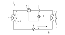
- FIG. 1 is a schematic configuration diagram showing a refrigeration cycle apparatus according to Embodiment 1;
- FIG. FIG. 2 is a perspective view showing the outdoor heat exchanger of FIG. 1;
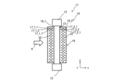
- 4 is a diagram showing a heat transfer member of the heat exchanger according to Embodiment 1;
- FIG. FIG. 5 is a diagram showing a modification of how to attach the fins to the heat transfer tubes of the heat exchanger according to Embodiment 1;
- FIG. 10 is a diagram showing a heat transfer member of a heat exchanger according to Embodiment 2;
- FIG. 10 is a diagram showing a heat transfer member of a heat exchanger according to Embodiment 3;
- FIG. 10 is a diagram showing a heat transfer member of a heat exchanger according to Embodiment 4;
- FIG. 10 is a diagram showing a modification of the heat transfer member of the heat exchanger according to Embodiment 4;
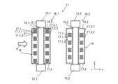
- FIG. 10 is a diagram showing a heat exchange member of a heat exchanger according to Embodiment 5;
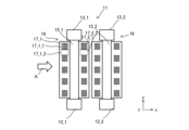
- FIG. 13 is a diagram showing a modification of the heat exchange member of the heat exchanger according to Embodiment 5;
- FIG. 10 is a view showing the arrangement of first heat transfer promoting portions and second heat transfer promoting portions formed in a fin of a comparative example;
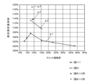
- FIG. 5 is a diagram showing the relationship between slit area ratio and air-side heat transfer performance;
- FIG. 1 is a schematic configuration diagram showing a refrigeration cycle apparatus according to Embodiment 1.
- a refrigeration cycle device is used as the air conditioner 1 .
- the air conditioner 1 has a compressor 2 , an outdoor heat exchanger 3 , an expansion valve 4 , an indoor heat exchanger 5 and a four-way valve 6 .
- a compressor 2, an outdoor heat exchanger 3, an expansion valve 4 and a four-way valve 6 are provided in the outdoor unit, and an indoor heat exchanger 5 is provided in the indoor unit.
- the compressor 2, the outdoor heat exchanger 3, the expansion valve 4, the indoor heat exchanger 5, and the four-way valve 6 are connected to each other via refrigerant pipes to form a refrigerant circuit in which the refrigerant can circulate.
- the operation of the compressor 2 performs a refrigeration cycle in which the refrigerant circulates through the compressor 2, the outdoor heat exchanger 3, the expansion valve 4, and the indoor heat exchanger 5 while undergoing phase changes.
- the outdoor unit is provided with an outdoor fan 7 that forces the outdoor air to pass through the outdoor heat exchanger 3.
- the outdoor heat exchanger 3 exchanges heat between the outdoor air stream generated by the operation of the outdoor fan 7 and the refrigerant.
- the indoor unit is provided with an indoor fan 8 for forcing indoor air to pass through the indoor heat exchanger 5 .
- the indoor heat exchanger 5 exchanges heat between the indoor air flow generated by the operation of the indoor fan 8 and the refrigerant.
- the operation of the air conditioner 1 can be switched between cooling operation and heating operation.
- the four-way valve 6 is an electromagnetic valve that switches refrigerant flow paths according to switching between the cooling operation and the heating operation of the air conditioner 1 .
- the four-way valve 6 guides the refrigerant from the compressor 2 to the outdoor heat exchanger 3 and the refrigerant from the indoor heat exchanger 5 to the compressor 2 during cooling operation, and guides the refrigerant from the compressor 2 during heating operation.
- the refrigerant from the outdoor heat exchanger 3 is guided to the compressor 2 while being guided to the indoor heat exchanger 5 .
- the direction of refrigerant flow during cooling operation is indicated by dashed arrows
- the direction of refrigerant flow during heating operation is indicated by solid arrows.
- the refrigerant compressed by the compressor 2 is sent to the outdoor heat exchanger 3 during cooling operation of the air conditioner 1 .
- the refrigerant releases heat to the outdoor air and is condensed.
- the refrigerant is sent to the expansion valve 4 , decompressed by the expansion valve 4 , and then sent to the indoor heat exchanger 5 .
- the refrigerant takes heat from indoor air in the indoor heat exchanger 5 and evaporates, and then returns to the compressor 2 . Therefore, during cooling operation of the air conditioner 1, the outdoor heat exchanger 3 functions as a condenser, and the indoor heat exchanger 5 functions as an evaporator.
- the refrigerant compressed by the compressor 2 is sent to the indoor heat exchanger 5.
- the indoor heat exchanger 5 the refrigerant releases heat to indoor air and is condensed.
- the refrigerant is sent to the expansion valve 4 , decompressed by the expansion valve 4 , and then sent to the outdoor heat exchanger 3 .
- the refrigerant takes heat from the outdoor air in the outdoor heat exchanger 3 and evaporates, and then returns to the compressor 2 . Therefore, during heating operation of the air conditioner 1, the outdoor heat exchanger 3 functions as an evaporator, and the indoor heat exchanger 5 functions as a condenser.
- FIG. 2 is a perspective view showing the outdoor heat exchanger 3 of FIG.
- the outdoor heat exchanger 3 has a heat exchanger 11 through which the airflow A generated by the operation of the outdoor fan 7 passes.
- the heat exchanger 11 has a first header tank 12, a second header tank 13, and a plurality of heat exchange members 14 connecting the first header tank 12 and the second header tank 13. .
- one of the refrigerant pipe from the expansion valve 4 and the refrigerant pipe from the four-way valve 6 is connected to the first header tank 12 and the other is connected to the second header tank 13 .
- the first header tank 12 and the second header tank 13 are arranged horizontally. Also, the second header tank 13 is arranged above the first header tank 12 . The first header tank 12 and the second header tank 13 are arranged parallel to each other along the z direction in FIG. 2, which is the third direction.
- the outer shape of the first header tank 12 and the second header tank 13 is a rectangular parallelepiped, but the shape is not limited.
- the outer shape of the first header tank 12 and the second header tank 13 may be, for example, a cylinder or an elliptical cylinder, and the cross-sectional shape can be changed as appropriate.
- the structure of the first header tank 12 and the second header tank 13 for example, it is possible to employ a cylinder whose both ends are closed or a stack of plate-like bodies having slits 21 formed therein. can.
- the first header tank 12 and the second header tank 13 are formed with coolant flow ports through which the coolant can flow in and out.
- the plurality of heat exchange members 14 are spaced apart from each other in the longitudinal direction of each of the first header tank 12 and the second header tank 13, that is, the z direction in FIG. Also, the plurality of heat exchange members 14 are arranged parallel to each other.
- the longitudinal direction of the plurality of heat exchange members 14 is the y-direction, which is the second direction crossing the z-direction in FIG.
- the y direction is the vertical direction in this embodiment.
- the longitudinal direction of each heat exchange member 14 is perpendicular to the longitudinal direction of each of the first header tank 12 and the second header tank 13 . Also, in this example, placement of members in spaces between the plurality of heat exchange members 14 is prohibited. Thereby, in this example, connection of the members to the mutually facing surfaces of the heat exchange members 14 adjacent to each other is avoided.
- the airflow A generated by the operation of the outdoor fan 7 passes through the multiple heat exchange members 14 .
- the airflow is along the direction intersecting with the respective longitudinal directions of the first header tank 12, the second header tank 13, and the heat exchange members 14, that is, along the x direction, which is the first direction in FIG. A passes between the plurality of heat exchange members 14 .
- the x-direction is orthogonal to the y-direction, which is the longitudinal direction of the heat exchange member 14 .
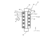
- FIG. 3 is a diagram showing the heat exchange member 14 of the heat exchanger 11 according to Embodiment 1.
- FIG. FIG. 3 is a view of the heat exchange member 14 shown in FIG. 2 as viewed in the z direction.
- white arrows indicate the direction of gas flow.
- FIG. 3 shows one heat exchange member 14 as an example among the plurality of heat exchange members 14 shown in FIG.
- the heat exchange member 14 has heat transfer tubes 15 and fins 16 .
- the heat transfer tubes 15 are arranged at predetermined intervals in the z direction.
- the heat transfer tubes 15 are circular tubes or flat tubes.
- the heat transfer pipe 15 extends in the y direction and connects the first header tank 12 and the second header tank 13.
- the heat transfer tubes 15 extend in the y direction, that is, in the vertical direction, and the refrigerant that has flowed into the heat transfer tubes 15 from the first header tank 12 or the second header tank 13 flows in the heat transfer tubes 15 in the vertical direction.
- the fins 16 have surfaces along the x-direction and the y-direction.
- the fins 16 are provided on the heat transfer tubes 15 so that their longitudinal directions are along the y direction.
- the fin 16 has a first extension 16_1 and a second extension 16_2.
- the first extending portion 16_1 and the second extending portion 16_2 are located outside the heat transfer tubes 15 in the x direction.
- the first extension portion 16_1 and the second extension portion 16_2 have the same size, and are provided on the heat transfer tube 15 so that the longitudinal direction thereof extends along the y direction.
- a first extension portion 16_1 and a second extension portion 16_2, which are individually configured, are attached to the sides of the heat transfer tubes 15 along the y direction.
- the first extending portion 16_1 has a rectangular shape when viewed from the z direction, and one of its long sides is provided on the heat transfer tube 15 .
- the short side of the first extending portion 16_1 is arranged to extend windward along the x direction.
- the first extending portion 16_1 has a first heat transfer enhancing region 17_1 provided upstream of the gas passing through the fins 16 and improving the heat transfer coefficient between the gas and the first extending portion 16_1.
- the first heat transfer enhancing region 17_1 is provided on the upstream side of the gas passing through the fins 16, and has a plurality of first heat transfer enhancing portions 17_1_1 that improve the heat transfer coefficient between the gas and the first extension portion 16_1. .
- the plurality of first heat transfer promoting portions 17_1_1 are arranged along the y direction.
- the first heat transfer promoting region 17_1 is positioned between the first heat transfer promoting portion 17_1_1 arranged on the upper side and the first heat transfer promoting portion 17_1_1 arranged on the lower side with respect to the y direction. It has a flat portion 17_1_2.
- a plurality of first flat portions 17_1_2 are provided in the first heat transfer promoting region 17_1.
- the first heat transfer promoting portions 17_1_1 and the first flat portions 17_1_2 are alternately arranged along the y direction.
- Three slits 21 are arranged in parallel along the x direction in the first heat transfer promoting portion 17_1_1.
- the slit 21 is an opening penetrating the fin 16 .
- a cut-and-raised portion instead of the slits 21 of the first heat transfer promoting portion 17_1_1, a cut-and-raised portion, a louver, or an uneven portion may be provided.
- the cut-and-raised portion is formed by raising the portion between two parallel slit-like cuts formed on the surface of the fin 16 in the z-direction.
- an opening having the same shape as the cut-and-raised is formed.
- the cut-and-raise protrudes from the plane of the fin 16 in the z-direction.
- a louver is formed by slanting a portion between two slits formed on the surface of the fins 16 with respect to the surface of the fins 16 .
- the fins 16 are formed with openings having the same shape as the louvers.
- the uneven portion is formed by protruding or recessing the surface of the fin 16 in the z direction.
- the first heat transfer promoting portion 17_1_1 may be a cut-and-raised portion, a louver, or an uneven portion.
- the first flat portion 17_1_2 is a flat rectangular region of the fin 16 between the first heat transfer promoting portions 17_1_1.
- the length in the y direction of the first flat portion 17_1_2 is shorter than the length in the y direction of the first heat transfer promoting portion 17_1_1.
- the second extending portion 16_2 has a rectangular shape when viewed in the z direction, and one of its long sides is provided on the heat transfer tube 15 .
- the short side of the second extending portion 16_2 is arranged to extend to the leeward side along the x direction.
- the second extension 16_2 has a second heat transfer enhancing region 17_2 that is provided on the downstream side of the gas passing through the fins 16 and that improves the heat transfer coefficient between the gas and the second extension 16_2.
- the second heat transfer enhancing region 17_2 is provided on the downstream side of the gas passing through the fins 16, and has a plurality of second heat transfer enhancing portions 17_2_1 that improve the heat transfer coefficient between the gas and the second extending portion 16_2. .
- the plurality of second heat transfer promoting portions 17_2_1 are arranged along the y direction.
- the second heat transfer promoting region 17_2 is a second flat portion positioned between the second heat transfer promoting portion 17_2_1 arranged on the upper side in the y direction and the second heat transfer promoting portion 17_2_1 arranged on the lower side. 17_2_2.
- a plurality of second flat portions 17_2_2 are provided in the second heat transfer promoting region 17_2.
- the second heat transfer promoting portions 17_2_1 and the second flat portions 17_2_2 are alternately arranged along the y direction.
- Three slits 21 are arranged in parallel along the x direction in the second heat transfer promoting portion 17_2_1.
- the slit 21 is an opening penetrating the fin 16 .
- a cut-and-raised portion instead of the slits 21 of the second heat transfer promoting portion 17_2_1, a cut-and-raised portion, a louver, or an uneven portion may be provided.
- the cut-and-raised portion is formed by raising the portion between two parallel slit-like cuts formed on the surface of the fin 16 in the z-direction.
- an opening having the same shape as the cut-and-raised is formed.
- the cut-and-raise protrudes from the plane of the fin 16 in the z-direction.
- a louver is formed by slanting a portion between two slits formed on the surface of the fins 16 with respect to the surface of the fins 16 .
- the fins 16 are formed with openings having the same shape as the louvers.
- the uneven portion is formed by protruding or recessing the surface of the fin 16 in the z direction.
- the second heat transfer promoting portion 17_2_1 may be a cut-and-raised portion, a louver, or an uneven portion.
- the second flat portion 17_2_2 is a flat rectangular region of the fin 16 between the second heat transfer promoting portions 17_2_1.
- the length in the y direction of the second flat portion 17_2_2 is shorter than the length in the y direction of the second heat transfer promoting portion 17_2_1.
- a second flat portion 17_2_2 is arranged in the second heat transfer enhancing region 17_2 downstream of the first heat transfer enhancing portion 17_1_1, and a second heat transfer enhancing region 17_2 is located downstream of the first flat portion 17_1_2.
- a second heat transfer promoting portion 17_2_1 is arranged in the heat promoting region 17_2. That is, the heat exchange member 14 has a region in which the first heat transfer promoting portion 17_1_1 and the second flat portion 17_2_2 are aligned and a region in which the first flat portion 17_1_2 and the second heat transfer promoting portion 17_2_1 are aligned in the x direction.
- the first heat transfer promoting portion 17_1_1 and the second heat transfer promoting portion 17_2_1 are arranged side by side in the x direction.
- the inflowing airflow flows in the x-direction on the surfaces of the first heat transfer enhancing regions 17_1 of the fins 16 .
- the first heat transfer enhancing region 17_1 part of the airflow is heat transfer enhanced in the slits 21 formed in the first heat transfer enhancing portion 17_1_1.
- the airflow flowing into the first flat portion 17_1_2 and the other airflow avoiding the first heat transfer promoting portion 17_1_1 flow in the x direction on the surface of the first flat portion 17_1_2.
- the airflow passes through the surface of the heat transfer tube 15, exchanges heat with the refrigerant flowing through the heat transfer tube 15, and then flows in the x direction on the surface of the second heat transfer enhancing region 17_2.
- part of the airflow is heat transfer promoted in the slits 21 formed in the second heat transfer promoting portion 17_2_1.
- the airflow flowing into the second flat portion 17_2_2 and the other airflow avoiding the second heat transfer promoting portion 17_2_1 flow in the x direction on the surface of the second flat portion 17_2_2.
- FIG. 4 is a diagram showing a modification of how the fins 16 of the heat exchanger 11 according to Embodiment 1 are attached to the heat transfer tubes 15.
- FIG. 4 is a diagram of the heat transfer tubes 15 and the fins 16 viewed in the y direction.
- the extending portion 16_2 may be integrally formed. The same applies to the other second, third, fourth and fifth embodiments.
- the fin 16 has a first extension portion 16_1, a second extension portion 16_2, and a main body portion 16_3.
- a first extension portion 16_1 and a second extension portion 16_2 are integrally formed with a main body portion 16_3.
- the body portion 16_3 is bent so as to come into contact with the heat transfer tube 15 , and the bent body portion 16_3 is attached to the heat transfer tube 15 .
- the heat exchange member 14 of the present embodiment can also be constructed by such an attachment mode.
- the positions of the first extending portion 16_1 and the second extending portion 16_2 with respect to the heat transfer tube 15 in the z-direction can be configured as follows.
- the first extension portion 16_1 and the second extension portion 16_2 are arranged so as to be aligned with the center of the heat transfer tube 15 in the z direction. This arrangement is also applied to a mode in which the first extension portion 16_1 and the second extension portion 16_2 are attached to the heat transfer tubes 15 individually.
- first extension portion 16_1 and the second extension portion 16_2 do not have to be aligned strictly with the center of the heat transfer tube 15 in the z direction, and the first extension portion 16_1 and the second extension portion 16_2 are within the range of the heat transfer tube 15 in the z direction.
- the existing portion 16_1 and the second extending portion 16_2 may be arranged.
- the first extension portion 16_1 and the second extension portion 16_2 may be arranged so as to be flush with the end surface of the heat transfer tube 15 in the z direction.
- the heat exchanger 11 has the heat transfer tubes 15 extending in the second direction intersecting the first direction in which the gas flows, and the surfaces along the first and second directions. , and fins 16 provided on the heat transfer tubes 15 .
- the fin 16 has a first extending portion 16_1 having a first heat transfer enhancing region 17_1 that is provided on the upstream side of the gas from the heat transfer tube 15 in the first direction and that improves the heat transfer coefficient with the gas.
- the fin 16 includes a second extending portion 16_2 having a second heat transfer promoting region 17_2 that is provided on the downstream side of the gas from the heat transfer tube 15 in the first direction and that improves the heat transfer coefficient with the gas.
- the heat exchanger 11 of Embodiment 1 is provided with the first heat transfer enhancing region 17_1 on the upstream side of the heat transfer tube 15 and the second heat transfer enhancing region 17_2 on the downstream side thereof, the fins 16 and The heat transfer coefficient with gas passing through the fins 16 can be improved.
- the gas when the gas is sent toward the heat transfer tube 15, the gas flows around the surface of the heat transfer tube 15 along the x direction so as to bypass the heat transfer tube 15, and the gas flows upstream of the heat transfer tube 15 in the gas flow direction. It is difficult for gas to flow to the ends and downstream ends (the left and right ends of the heat transfer tube 15 illustrated in FIG. 4 ).
- the first extending portion 16_1 and the second extending portion 16_2 extending in the x-direction in which the gas flows are provided on the upstream side and the downstream side of the heat transfer tube 15, respectively.
- the first extension portion 16_1 is provided with a first heat transfer enhancing region 17_1 that improves the heat transfer coefficient with the gas
- the second extension portion 16_2 is provided with a second heat transfer enhancement region that improves the heat transfer coefficient with the gas.
- a thermal enhancement region 17_2 is provided. Therefore, the heat transfer coefficient between the gas flowing in the x direction and the fins 16 can be improved.
- a second flat portion 17_2_2 is arranged in the second heat transfer promoting region 17_2 aligned with the first heat transfer promoting portion 17_1_1 in the x direction, and the second heat transfer promoting portion 17_2_2 is arranged in the x direction of the first flat portion 17_1_2 in the x direction.
- a second heat transfer promoting portion 17_2_1 is arranged in the promoting region 17_2. Therefore, even if the gas flowing in the x direction flows through the first flat portion 17_1_2 on the upstream side, it easily flows through the second heat transfer promoting portion 17_2_1 on the downstream side.
- the gas flowing through the first flat portion 17_1_2 on the downstream side flows around the first heat transfer promoting portion 17_1_1 on the upstream side. Therefore, the heat transfer coefficient of the fins 16 can be improved.
- the path of the airflow passing through the first flat portion 17_1_2 or the second flat portion 17_2_2 can be lengthened, so that the substantial heat transfer area of the fin 16 can be increased. can do.
- the first heat transfer promoting portions 17_1_1 and the first flat portions 17_1_2 are alternately arranged along the y direction, which is the second direction.
- the second heat transfer promoting portions 17_2_1 and the second flat portions 17_2_2 are alternately arranged along the y direction, which is the second direction. Therefore, when looking at the pressure loss distribution of the entire fin 16, the pressure loss distribution of the airflow in the y direction approaches uniformity. Therefore, the airflow passing through the first flat portion 17_1_2 and the second flat portion 17_2_2 is reduced, and as a result, the heat transfer coefficient between the airflow and the fins 16 is improved.
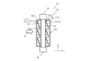
- the heat exchange member 14 of the heat exchanger 11 according to the second embodiment has a size of the first flat portion 17_1_2 and the first flat portion 17_1_2 compared to the heat exchange member 14 of the heat exchanger 11 according to the first embodiment. is different.
- FIG. 5 is a diagram showing the heat exchange member 14 of the heat exchanger 11 according to the second embodiment.
- white arrows indicate the direction of gas flow.
- FIG. 5 shows one heat exchange member 14 as an example among the plurality of heat exchange members 14 shown in FIG.
- the lengths of the first heat transfer promoting portion 17_1_1, the first flat portion 17_1_2, the second heat transfer promoting portion 17_2_1, and the second flat portion 17_2_2 in the x direction and the y direction are the same. Note that only the y-direction lengths of the first heat transfer promoting portion 17_1_1, the first flat portion 17_1_2, the second heat transfer promoting portion 17_2_1, and the second flat portion 17_2_2 may be the same.
- the position in the y direction of the first heat transfer enhancing portion 17_1_1 is the same as the position in the y direction of the second flat portion 17_2_2 in the second heat transfer enhancing region 17_2.
- the position in the y direction of the first flat portion 17_1_2 is the same as the position in the y direction of the second heat transfer promoting portion 17_2_1 in the second heat transfer promoting region 17_2.
- the positions of the first heat transfer promoting portion 17_1_1 and the second heat transfer promoting portion 17_2_1 formed in the fins 16 of the heat exchanger 11 according to the second embodiment are shifted in the y direction.
- the first flat portion 17_1_2 and the second flat portion 17_2_2 are displaced from each other in the y direction.
- the heat exchanger 11 has the heat transfer tubes 15 extending in the second direction intersecting the first direction in which the gas flows, the surfaces along the first direction and the second direction, and fins 16 provided on the heat transfer tubes 15 .
- the fin 16 has a first extending portion 16_1 having a first heat transfer enhancing region 17_1 that is provided on the upstream side of the gas from the heat transfer tube 15 in the first direction and that improves the heat transfer coefficient with the gas.
- the fin 16 includes a second extending portion 16_2 having a second heat transfer promoting region 17_2 that is provided on the downstream side of the gas from the heat transfer tube 15 in the first direction and that improves the heat transfer coefficient with the gas.
- the heat exchanger 11 of Embodiment 1 is provided with the first heat transfer enhancing region 17_1 on the upstream side of the heat transfer tube 15 and the second heat transfer enhancing region 17_2 on the downstream side thereof, the fins 16 and The heat transfer coefficient with gas passing through the fins 16 can be improved.
- the gas when the gas is sent toward the heat transfer tube 15, the gas flows around the surface of the heat transfer tube 15 along the x direction so as to bypass the heat transfer tube 15, and the gas flows upstream of the heat transfer tube 15 in the gas flow direction. It is difficult for gas to flow to the ends and downstream ends (the left and right ends of the heat transfer tube 15 illustrated in FIG. 4 ).
- the first extending portion 16_1 and the second extending portion 16_2 extending in the x-direction in which the gas flows are provided on the upstream side and the downstream side of the heat transfer tube 15, respectively.
- the first extension portion 16_1 is provided with a first heat transfer enhancing region 17_1 that improves the heat transfer coefficient with the gas
- the second extension portion 16_2 is provided with a second heat transfer enhancement region that improves the heat transfer coefficient with the gas.
- a thermal enhancement region 17_2 is provided. Therefore, the heat transfer coefficient between the gas flowing in the x direction and the fins 16 can be improved.
- the lengths in the x direction and the y direction of the first heat transfer promoting portion 17_1_1, the first flat portion 17_1_2, the second heat transfer promoting portion 17_2_1, and the second flat portion 17_2_2 are the same. Therefore, when manufacturing the fin 16, the first heat transfer promoting portion 17_1_1 and the second heat transfer promoting portion 17_2_1 can be formed in the fin 16 by progressive pressing.
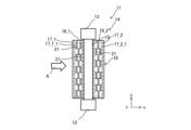
- the heat exchange member 14 of the heat exchanger 11 according to Embodiment 3 has the first flat portion 17_1_2 and the second flat portion 17_2_2 provided in the heat exchange member 14 of the heat exchanger 11 according to Embodiment 1. It does not.
- FIG. 6 is a diagram showing the heat exchange member 14 of the heat exchanger 11 according to the third embodiment.
- white arrows indicate the direction of gas flow.
- FIG. 6 shows one heat exchange member 14 as an example among the plurality of heat exchange members 14 shown in FIG.
- the first heat transfer enhancing region 17_1 includes a plurality of first heat transfer enhancing portions 17_1_1 that are arranged along the y direction and improve the heat transfer coefficient with gas.
- the second heat transfer enhancing region 17_2 has a plurality of second heat transfer enhancing portions 17_2_1 that are arranged along the y direction and improve the heat transfer coefficient with gas.
- the first heat transfer promoting portion 17_1_1 has one slit 21.
- the slits 21 provided in the first heat transfer promoting portions 17_1_1 adjacent to each other in the y-direction have different positions in the x-direction.
- a plurality of slits 21 formed in the first heat transfer promoting portion 17_1_1 may be formed along the x direction.
- the second heat transfer promoting portion 17_2_1 has one slit 21.
- the slits 21 provided in the second heat transfer promoting portions 17_2_1 adjacent in the y direction have different positions in the x direction.
- a plurality of slits 21 formed in the second heat transfer promoting portion 17_2_1 may be formed along the x direction.
- the sum of the number of slits 21 formed in the first heat transfer promoting portion 17_1_1 in the x direction and the number of slits 21 formed in the second heat transfer promoting portion 17_2_1 in the x direction is constant. .
- a plurality of first heat transfer promoting portions 17_1_1 and second heat transfer promoting portions 17_2_1 are provided along the y direction of the fins 16 .
- the sum of the number of slits 21 formed in the first heat transfer promoting portion 17_1_1 in the x direction and the number of slits 21 formed in the second heat transfer promoting portion 17_2_1 in the x direction is constant. That is, a plurality of sets of slits 21 provided in the same number (two in the example of FIG. 6) in the x direction are arranged in the y direction. Therefore, the pressure loss distribution in the y direction of the airflow can be made uniform. Thereby, the heat transfer coefficient of the fins 16 of the heat exchanger 11 is improved.
- the heat exchange member 14 of the heat exchanger 11 according to Embodiment 4 has a first pattern of arrangement of the slits 21 formed in the first heat transfer promoting portion 17_1_1 and slits formed in the second heat transfer promoting portion 17_2_1. 21 is displaced in the x direction from the second pattern of arrangement.
- FIG. 7 is a diagram showing the heat exchange member 14 of the heat exchanger 11 according to the fourth embodiment.
- white arrows indicate the direction of gas flow.
- FIG. 7 shows one heat exchange member 14 as an example among the plurality of heat exchange members 14 shown in FIG.
- the first heat transfer enhancing region 17_1 includes a plurality of first heat transfer enhancing portions 17_1_1 that are arranged along the y direction and improve the heat transfer coefficient with gas.
- the second heat transfer enhancing region 17_2 has a plurality of second heat transfer enhancing portions 17_2_1 that are arranged along the y direction and improve the heat transfer coefficient with gas.
- a first pattern of slits 21 is formed in the plurality of first heat transfer promoting portions 17_1_1.
- two slits 21 arranged in the x direction in the first heat transfer promoting portion 17_1_1 and one slit 21 provided adjacent to the two slits 21 in the y direction are continuous in the y direction. It's a pattern.
- one slit 21 adjacent in the y direction is arranged at an intermediate position between two slits aligned in the x direction.
- a second pattern of slits 21 is formed in the plurality of second heat transfer promoting portions 17_2_1.
- the second pattern includes one slit 21 arranged in the x direction in the second heat transfer promoting portion 17_2_1 and two slits 21 arranged on both sides of the one slit 21 below the one slit 21 in the y direction. is a continuous pattern in the y direction.
- the arrangement of the slits 21 is shifted in the y direction between the first pattern and the second pattern.
- the sum of the number of slits 21 formed in the first heat transfer promoting portion 17_1_1 and the number of slits 21 formed in the second heat transfer promoting portion 17_2_1 is three and is constant.
- the first pattern and the second pattern are not limited to the example shown in FIG. 7, and patterns of various numbers of slits 21 can be adopted.
- it is a pattern in which a set of three slits 21 arranged in the x direction and a single slit 21 arranged in the x direction is repeatedly arranged in the y direction.
- FIG. 8 is a diagram showing a modification of the heat exchange member 14 of the heat exchanger 11 according to the fourth embodiment.
- the first flat portion 17_1_2 is arranged below the first heat transfer promoting portion 17_1_1 in the y direction.
- the first heat transfer promoting portion 17_1_1 is arranged in the y direction via the first flat portion 17_1_2.
- a first pattern of square uneven portions 22 is formed on the plurality of first heat transfer promoting portions 17_1_1.
- the first pattern includes two uneven portions 22 arranged in the x-direction on the first heat transfer promoting portion 17_1_1 and one uneven portion 22 provided adjacent to the two uneven portions 22 in the y-direction.
- the pattern is continuous in the y direction via the flat portion 17_1_2.
- a second pattern of square uneven portions 22 is formed on the plurality of second heat transfer promoting portions 17_2_1.
- the second pattern consists of two uneven portions 22 arranged in the x-direction on the second heat transfer promoting portion 17_2_1 and one uneven portion 22 arranged below the two uneven portions 22 in the y-direction.
- the pattern is continuous in the y direction via the flat portion 17_2_2.
- the arrangement of the uneven portions 22 is shifted in the y direction, which is the second direction, between the first pattern and the second pattern.
- the sum of the number of uneven portions 22 formed in the first heat transfer promoting portion 17_1_1 and the number of uneven portions 22 formed in the second heat transfer promoting portion 17_2_1 is constant at 3. be.
- first flat portion 17_1_2 and the second flat portion 17_2_2 may be omitted.
- the first pattern of arrangement of slits or unevenness provided in the first heat transfer promoting portion and the second pattern of arrangement of slits or unevenness provided in the second heat transfer promoting portion The pattern is offset in the second direction. Therefore, the pressure loss distribution in the y direction of the airflow can be reduced. Thereby, the heat transfer coefficient of the fins 16 of the heat exchanger 11 is improved.
- the first pattern and the second pattern can be formed by progressive pressing.
- Embodiment 5 Next, the heat exchanger 11 according to Embodiment 5 will be described.
- FIG. 9 is a diagram showing the heat exchange member 14 of the heat exchanger 11 according to the fifth embodiment.
- white arrows indicate the direction of gas flow.
- the plurality of heat exchange members 14 shown in FIG. 2 are provided in at least two rows in the x direction. indicates
- the fins 16 are provided on the first heat transfer tube 15_1 along the y direction, which is the vertical direction.
- the first heat transfer pipe 15_1 is provided between the first header tank 12_1 and the second header tank 13_1.
- the fin 16 has a first extension 16_1 and a second extension 16_2.
- the first extending portion 16_1 of the fin 16 has a rectangular shape, one of the long sides is attached to the first heat transfer tube 15_1 along the y direction, and the short side extends windward along the x direction. are arranged as follows.
- the second extending portion 16_2 of the fin 16 has a rectangular shape, one of the long sides is attached to the first heat transfer tube 15_1 along the y direction, and the short side extends downwind along the x direction. are arranged as follows.
- the first extending portion 16_1 is provided upstream of the gas passing through the fins 16 .
- the first extending portion 16_1 has a rectangular shape when viewed in the z-direction, and its long side is provided on the first heat transfer tube 15_1.
- the first extension portion 16_1 is provided with a first heat transfer enhancement region 17_1 that improves the heat transfer coefficient of the first extension portion 16_1 with the gas.
- the first heat transfer enhancing region 17_1 includes a plurality of first heat transfer enhancing portions 17_1_1 arranged along the y direction to improve the heat transfer coefficient with gas, and a plurality of first flattened regions 17_1_1 arranged along the y direction. 17_1_2.
- the first heat transfer promoting portions 17_1_1 and the first flat portions 17_1_2 are alternately arranged along the y direction.
- the first flat portion 17_1_2 is a flat rectangular region of the fin 16 between the first heat transfer promoting portions 17_1_1.
- the length in the y direction of the first flat portion 17_1_2 is the same as the length in the y direction of the first heat transfer promoting portion 17_1_1.
- the second extending portion 16_2 is provided downstream of the gas passing through the fins 16 .
- the second extending portion 16_2 has a rectangular shape when viewed in the z-direction, and the long side thereof is provided on the first heat transfer tube 15_1.
- the second extension portion 16_2 is provided with a second heat transfer enhancement region 17_2 that improves the heat transfer rate between the second extension portion 16_2 and the gas.
- the second heat transfer enhancing regions 17_2 are arranged along the y direction and include a plurality of second heat transfer enhancing portions 17_2_1 that improve the heat transfer coefficient with the gas, and a plurality of first flattened portions 17_2_1 arranged along the y direction. 17_1_2.
- the second heat transfer promoting portions 17_2_1 and the second flat portions 17_2_2 are alternately arranged along the y direction.
- the second flat portion 17_2_2 is a flat rectangular region of the fin 16 between the second heat transfer promoting portions 17_2_1.
- the length in the y direction of the second flat portion 17_2_2 is the same as the length in the y direction of the second heat transfer promoting portion 17_2_1.
- a second heat transfer promoting portion 17_2_1 is arranged in the x direction of the first heat transfer promoting portion 17_1_1, and a second flat portion 17_2_2 is arranged in the x direction of the first flat portion 17_1_2.
- a fin 16 is provided along the y direction on the second heat transfer tube 15_2.
- the second heat transfer pipe 15_2 is provided between the first header tank 12_1 and the second header tank 13_1.
- the fin 16 has a first extension 16_1 and a second extension 16_2.
- the first extension portion 16_1 of the fin 16 has a rectangular shape, one of the long sides is attached to the second heat transfer tube 15_2 along the y direction, and the short side extends windward along the x direction. are arranged as follows.
- the second extending portion 16_2 of the fin 16 has a rectangular shape, one of the long sides is attached to the second heat transfer tube 15_2 along the y direction, and the short side extends downwind along the x direction. are arranged as follows.
- the first extending portion 16_1 is provided upstream of the gas passing through the fins 16 .
- the first extending portion 16_1 has a rectangular shape when viewed in the z-direction, and its long side is provided on the first heat transfer tube 15_1.
- the first extension portion 16_1 is provided with a first heat transfer enhancement region 17_1 that improves the heat transfer coefficient of the first extension portion 16_1 with the gas.
- the first heat transfer enhancing region 17_1 includes a plurality of first heat transfer enhancing portions 17_1_1 arranged along the y direction to improve the heat transfer coefficient with gas, and a plurality of first flattened regions 17_1_1 arranged along the y direction. 17_1_2.
- the first heat transfer promoting portions 17_1_1 and the first flat portions 17_1_2 are alternately arranged along the y direction.
- the first flat portion 17_1_2 is a flat rectangular region of the fin 16 between the first heat transfer promoting portions 17_1_1.
- the length in the y direction of the first flat portion 17_1_2 is the same as the length in the y direction of the first heat transfer promoting portion 17_1_1.
- the second extending portion 16_2 is provided downstream of the gas passing through the fins 16 .
- the second extending portion 16_2 has a rectangular shape when viewed in the z-direction, and the long side thereof is provided on the first heat transfer tube 15_1.
- the second extension portion 16_2 is provided with a second heat transfer enhancement region 17_2 that improves the heat transfer rate between the second extension portion 16_2 and the gas.
- the second heat transfer enhancing regions 17_2 are arranged along the y direction and include a plurality of second heat transfer enhancing portions 17_2_1 that improve the heat transfer coefficient with the gas, and a plurality of first flattened portions 17_2_1 arranged along the y direction. 17_1_2.
- the second heat transfer promoting portions 17_2_1 and the second flat portions 17_2_2 are alternately arranged along the y direction.
- the second flat portion 17_2_2 is a flat rectangular region of the fin 16 between the second heat transfer promoting portions 17_2_1.
- the length in the y direction of the second flat portion 17_2_2 is the same as the length in the y direction of the second heat transfer promoting portion 17_2_1.
- a second heat transfer promoting portion 17_2_1 is arranged in the x direction of the first heat transfer promoting portion 17_1_1, and a second flat portion 17_2_2 is arranged in the x direction of the first flat portion 17_1_2.
- the position in the y direction of the second heat transfer promoting portion 17_2_1 formed on the fins 16 provided on the first heat transfer tube 15_1 corresponds to the position of the first heat transfer promoting portion formed on the fins 16 provided on the second heat transfer tube 15_2. It is different from the y-direction position of 17_1_1.
- FIG. 10 is a diagram showing a modification of the heat exchange member 14 of the heat exchanger 11 according to the fifth embodiment.
- white arrows indicate the direction of gas flow.
- a plurality of heat exchange members 14 shown in FIG. 2 are provided at intervals in the z direction, and are provided in three rows in the x direction.
- the first row heat exchange member 14_1, the second row heat exchange member 14_2, and the third row heat exchange member 14_3 are shown as examples.
- the first heat transfer promoting portion 17_1_1 and the first flat portion 17_1_2 formed on the fins 16 provided on the first heat transfer tube 15_1, the second heat transfer tube 15_2 and the third heat transfer tube 15_3 are the same as in FIG.
- the position in the second direction of the second heat transfer promoting portion 17_2_1 provided in the first heat transfer tube 15_1 is the second position of the first heat transfer promoting portion 17_1_1 provided in the second heat transfer tube 15_2. Different from the position of the direction.
- the y-direction position of the second heat transfer promoting portion 17_2_1 provided in the second heat transfer tube 15_2 is different from the y-direction position of the first heat transfer promoting portion 17_1_1 provided in the third heat transfer tube 15_3.
- the positions of the first heat transfer promoting portions 17_1_1 of the adjacent heat transfer tubes 15 in the second direction are different. Therefore, the pressure loss distribution of the airflow in the y direction becomes uniform, and the amount of airflow passing through the first flat portion 17_1_2 and the second flat portion 17_2_2 is reduced.
- the fins 16 extending on the windward side are formed with the first heat transfer promoting portions 17_1_1, and the fins 16 extending on the leeward side are formed with the second heat transfer promoting portions 17_2_1. is formed, the effect on the heat transfer efficiency of the fins 16 is great.
- Embodiments 1 to 5 describe that the first heat transfer promoting portion 17_1_1 and the second heat transfer promoting portion 17_2_1 may be configured by one or more of cut-and-raised portions, slits, louvers, and uneven portions. bottom.
- cut-and-raised, slits, or louvers are employed, openings are provided in the fins 16, so the plane portions of the fins 16, that is, the area for exchanging heat with gas is reduced.
- the entire outer peripheral surface of the heat transfer tubes and the fins are in contact with each other.
- the direction of heat conduction to the fins 16 is 360 degrees when viewed in cross section of the heat transfer tube 15 . Therefore, the effect of providing the openings in the fins 16 to reduce the heat exchange area is limited.
- the fins 16 are connected to the sides of the heat transfer tubes 15 along the y direction or to the xy plane (FIG. 4) of the heat transfer tubes 15. Therefore, the direction of heat conduction from the heat transfer tube 15 to the fins 16 is limited. Therefore, in Embodiments 1 to 5, the effect of the openings in the fins 16 on the reduction in the heat exchange area is greater than in the heat exchanger in which the heat transfer tubes pass through the fins. Therefore, the opening area of the fins 16 and the arrangement of the first heat transfer promoting portion 17_1_1 and the second heat transfer promoting portion 17_2_1 in Embodiments 1 to 5 will be described below.
- FIG. 11 is a diagram showing the arrangement of the first heat transfer promoting portion 17_1_1 and the second heat transfer promoting portion 17_2_1 formed on the fin 16 of the comparative example.
- FIG. 11 shows a first heat transfer tube 15_1 and a second heat transfer tube 15_2 spaced apart in the x direction.
- the second heat transfer promoting portion 17_2_1 is arranged in the x direction of the first heat transfer promoting portion 17_1_1.
- a second flat portion 17_2_2 is arranged in the x direction of the first flat portion 17_1_2.
- FIG. 12 is a diagram showing the relationship between the slit area ratio and the air-side heat transfer performance.
- the "slit area ratio” is slit area/fin 16 area.
- Air-side heat transfer performance is the air-side heat transfer area of the fins 16 ⁇ air-side heat conductivity.
- g_1 indicates the characteristics of the slit area ratio and the air-side heat transfer performance of the heat exchanger 11 shown in FIG. g_2 represents the characteristics of the slit area ratio and the air-side heat transfer performance of the heat exchanger 11 shown in FIG. g_3 shows the characteristics of the slit area ratio and the air-side heat transfer performance when the heat exchangers 11 shown in FIG. 5 are arranged in two rows in the x direction.
- g_4 shows the characteristics of the slit area ratio and the air-side heat transfer performance when the heat exchangers 11 shown in FIG. 8 are arranged in two rows in the x direction.
- the fin 16 shown in FIG. 8 has the highest air-side heat transfer performance.
- the fins 16 shown in FIG. 5 and the fins 16 shown in FIG. 9 have high air-side heat transfer performance, and the fins 16 shown in FIGS.
- the heat transfer performance on the air side is higher than that of the fins 16 .
- the other fins 16 shown in the first to fifth embodiments also have higher air-side heat transfer performance than the fins 16 shown in FIG. 11 as a comparative example.
- the air side heat transfer performance is higher than when it is 15%. . Therefore, when adopting the configuration of the heat exchanger 11 of FIG. 9, it is desirable to set the slit area ratio to 7.5%.
- the air-side heat transfer performance peaks at a slit area ratio of 7.5%.
- the slit area ratio is preferably 5 to 10% for any of the patterns of Embodiments 1 to 5.
- the shapes of the first heat transfer promoting portion 17_1_1 and the second heat transfer promoting portion 17_2_1 may be different.
- the first heat transfer promoting portion 17_1_1 may be the slit 21, and the second heat transfer promoting portion 17_2_1 may be uneven.
- the number of slits 21 of the first heat transfer promoting portion 17_1_1 may be smaller than the number of slits 21 of the second heat transfer promoting portion 17_2_1.
- first heat transfer promoting portion 17_1_1 may be different.
- first heat transfer promoting portion 17_1_1 may have slits 21 and louvers.
- second heat transfer promoting portion 17_2_1 may also have a different shape.
- the second heat transfer promoting portion 17_2_1 may have a slit 21 and an uneven shape.
- Embodiments 1 to 5 are presented as examples and are not intended to limit the scope of claims. Embodiments can be implemented in various other forms, and various omissions, replacements, and modifications can be made without departing from the gist of the embodiments. These embodiments and modifications thereof are included in the scope and gist of the embodiments.
Landscapes
- Engineering & Computer Science (AREA)
- Physics & Mathematics (AREA)
- Thermal Sciences (AREA)
- Mechanical Engineering (AREA)
- General Engineering & Computer Science (AREA)
- Geometry (AREA)
- Heat-Exchange Devices With Radiators And Conduit Assemblies (AREA)
Priority Applications (4)
| Application Number | Priority Date | Filing Date | Title |
|---|---|---|---|
| CN202180104564.8A CN118339417A (zh) | 2021-12-06 | 2021-12-06 | 热交换器 |
| PCT/JP2021/044701 WO2023105566A1 (ja) | 2021-12-06 | 2021-12-06 | 熱交換器 |
| JP2023565674A JPWO2023105566A1 (cg-RX-API-DMAC7.html) | 2021-12-06 | 2021-12-06 | |
| US18/697,129 US20240410659A1 (en) | 2021-12-06 | 2021-12-06 | Heat exchanger |
Applications Claiming Priority (1)
| Application Number | Priority Date | Filing Date | Title |
|---|---|---|---|
| PCT/JP2021/044701 WO2023105566A1 (ja) | 2021-12-06 | 2021-12-06 | 熱交換器 |
Publications (1)
| Publication Number | Publication Date |
|---|---|
| WO2023105566A1 true WO2023105566A1 (ja) | 2023-06-15 |
Family
ID=86729773
Family Applications (1)
| Application Number | Title | Priority Date | Filing Date |
|---|---|---|---|
| PCT/JP2021/044701 Ceased WO2023105566A1 (ja) | 2021-12-06 | 2021-12-06 | 熱交換器 |
Country Status (4)
| Country | Link |
|---|---|
| US (1) | US20240410659A1 (cg-RX-API-DMAC7.html) |
| JP (1) | JPWO2023105566A1 (cg-RX-API-DMAC7.html) |
| CN (1) | CN118339417A (cg-RX-API-DMAC7.html) |
| WO (1) | WO2023105566A1 (cg-RX-API-DMAC7.html) |
Citations (4)
| Publication number | Priority date | Publication date | Assignee | Title |
|---|---|---|---|---|
| JPS6237692A (ja) * | 1985-08-12 | 1987-02-18 | Hitachi Ltd | 熱交換器 |
| JP2003247795A (ja) * | 2002-02-22 | 2003-09-05 | Toshiba Kyaria Kk | 熱交換器 |
| WO2019026243A1 (ja) | 2017-08-03 | 2019-02-07 | 三菱電機株式会社 | 熱交換器、及び冷凍サイクル装置 |
| WO2020044391A1 (ja) * | 2018-08-27 | 2020-03-05 | 三菱電機株式会社 | 熱交換器、熱交換器ユニット、及び冷凍サイクル装置 |
Family Cites Families (2)
| Publication number | Priority date | Publication date | Assignee | Title |
|---|---|---|---|---|
| JPH09159386A (ja) * | 1995-12-13 | 1997-06-20 | Sanden Corp | 多管式熱交換器 |
| DE19751768A1 (de) * | 1997-11-21 | 1999-05-27 | Bosch Siemens Hausgeraete | Verdampfer |
-
2021
- 2021-12-06 JP JP2023565674A patent/JPWO2023105566A1/ja not_active Withdrawn
- 2021-12-06 US US18/697,129 patent/US20240410659A1/en not_active Abandoned
- 2021-12-06 CN CN202180104564.8A patent/CN118339417A/zh active Pending
- 2021-12-06 WO PCT/JP2021/044701 patent/WO2023105566A1/ja not_active Ceased
Patent Citations (4)
| Publication number | Priority date | Publication date | Assignee | Title |
|---|---|---|---|---|
| JPS6237692A (ja) * | 1985-08-12 | 1987-02-18 | Hitachi Ltd | 熱交換器 |
| JP2003247795A (ja) * | 2002-02-22 | 2003-09-05 | Toshiba Kyaria Kk | 熱交換器 |
| WO2019026243A1 (ja) | 2017-08-03 | 2019-02-07 | 三菱電機株式会社 | 熱交換器、及び冷凍サイクル装置 |
| WO2020044391A1 (ja) * | 2018-08-27 | 2020-03-05 | 三菱電機株式会社 | 熱交換器、熱交換器ユニット、及び冷凍サイクル装置 |
Also Published As
| Publication number | Publication date |
|---|---|
| CN118339417A (zh) | 2024-07-12 |
| US20240410659A1 (en) | 2024-12-12 |
| JPWO2023105566A1 (cg-RX-API-DMAC7.html) | 2023-06-15 |
Similar Documents
| Publication | Publication Date | Title |
|---|---|---|
| CN203464822U (zh) | 热交换器及空调机 | |
| JP5195733B2 (ja) | 熱交換器及びこれを備えた冷凍サイクル装置 | |
| US20090173480A1 (en) | Louvered air center with vortex generating extensions for compact heat exchanger | |
| US20210156622A1 (en) | Microchannel flat tube and microchannel heat exchanger | |
| US20200217588A1 (en) | Heat exchanger and refrigeration cycle apparatus | |
| JP7292510B2 (ja) | 熱交換器及び空気調和機 | |
| JP7140988B2 (ja) | 熱交換器 | |
| CN114322105B (zh) | 换热器和空调系统 | |
| WO2019008997A1 (ja) | 空気調和機の室外熱交換器及びこれを備える空気調和機 | |
| CN118009763A (zh) | 热交换器及制冷循环装置 | |
| CN111902683B (zh) | 热交换器及制冷循环装置 | |
| US20210180878A1 (en) | Heat exchanger, heat exchanger unit, and refrigeration cycle apparatus | |
| KR20060012303A (ko) | 열교환기용 핀, 열교환기, 응축기, 및 증발기 | |
| KR101287775B1 (ko) | 공기 조화기 | |
| JP6678413B2 (ja) | 空気調和機 | |
| WO2016071945A1 (ja) | 空気調和装置の室内機 | |
| WO2017068723A1 (ja) | 熱交換器及び冷凍サイクル装置 | |
| JP7006376B2 (ja) | 熱交換器 | |
| JP2013257095A (ja) | フィンレス熱交換器 | |
| US20240410659A1 (en) | Heat exchanger | |
| WO2024089927A1 (ja) | 熱交換器およびこの熱交換器を備えた冷凍サイクル装置 | |
| CN113785168B (zh) | 热交换器及制冷循环装置 | |
| WO2022220159A1 (ja) | 熱交換器 | |
| WO2023032155A1 (ja) | 熱交換器、冷凍サイクル装置及び熱交換器の製造方法 | |
| JP6582373B2 (ja) | 熱交換器 |
Legal Events
| Date | Code | Title | Description |
|---|---|---|---|
| 121 | Ep: the epo has been informed by wipo that ep was designated in this application |
Ref document number: 21967073 Country of ref document: EP Kind code of ref document: A1 |
|
| WWE | Wipo information: entry into national phase |
Ref document number: 2023565674 Country of ref document: JP |
|
| WWE | Wipo information: entry into national phase |
Ref document number: 2401002260 Country of ref document: TH |
|
| WWE | Wipo information: entry into national phase |
Ref document number: 202180104564.8 Country of ref document: CN |
|
| WWE | Wipo information: entry into national phase |
Ref document number: 2021967073 Country of ref document: EP |
|
| NENP | Non-entry into the national phase |
Ref country code: DE |
|
| ENP | Entry into the national phase |
Ref document number: 2021967073 Country of ref document: EP Effective date: 20240708 |
|
| 122 | Ep: pct application non-entry in european phase |
Ref document number: 21967073 Country of ref document: EP Kind code of ref document: A1 |