WO2023100950A1 - アダプタ及び光学アセンブリ - Google Patents
アダプタ及び光学アセンブリ Download PDFInfo
- Publication number
- WO2023100950A1 WO2023100950A1 PCT/JP2022/044255 JP2022044255W WO2023100950A1 WO 2023100950 A1 WO2023100950 A1 WO 2023100950A1 JP 2022044255 W JP2022044255 W JP 2022044255W WO 2023100950 A1 WO2023100950 A1 WO 2023100950A1
- Authority
- WO
- WIPO (PCT)
- Prior art keywords
- holding
- optical
- adapter
- section
- eyepiece
- Prior art date
- Legal status (The legal status is an assumption and is not a legal conclusion. Google has not performed a legal analysis and makes no representation as to the accuracy of the status listed.)
- Ceased
Links
Images




























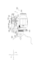
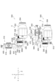
Classifications
-
- G—PHYSICS
- G02—OPTICS
- G02B—OPTICAL ELEMENTS, SYSTEMS OR APPARATUS
- G02B21/00—Microscopes
-
- G—PHYSICS
- G02—OPTICS
- G02B—OPTICAL ELEMENTS, SYSTEMS OR APPARATUS
- G02B21/00—Microscopes
- G02B21/36—Microscopes arranged for photographic purposes or projection purposes or digital imaging or video purposes including associated control and data processing arrangements
-
- G—PHYSICS
- G02—OPTICS
- G02B—OPTICAL ELEMENTS, SYSTEMS OR APPARATUS
- G02B23/00—Telescopes, e.g. binoculars; Periscopes; Instruments for viewing the inside of hollow bodies; Viewfinders; Optical aiming or sighting devices
-
- G—PHYSICS
- G02—OPTICS
- G02B—OPTICAL ELEMENTS, SYSTEMS OR APPARATUS
- G02B23/00—Telescopes, e.g. binoculars; Periscopes; Instruments for viewing the inside of hollow bodies; Viewfinders; Optical aiming or sighting devices
- G02B23/16—Housings; Caps; Mountings; Supports, e.g. with counterweight
- G02B23/18—Housings; Caps; Mountings; Supports, e.g. with counterweight for binocular arrangements
-
- G—PHYSICS
- G03—PHOTOGRAPHY; CINEMATOGRAPHY; ANALOGOUS TECHNIQUES USING WAVES OTHER THAN OPTICAL WAVES; ELECTROGRAPHY; HOLOGRAPHY
- G03B—APPARATUS OR ARRANGEMENTS FOR TAKING PHOTOGRAPHS OR FOR PROJECTING OR VIEWING THEM; APPARATUS OR ARRANGEMENTS EMPLOYING ANALOGOUS TECHNIQUES USING WAVES OTHER THAN OPTICAL WAVES; ACCESSORIES THEREFOR
- G03B17/00—Details of cameras or camera bodies; Accessories therefor
- G03B17/02—Bodies
- G03B17/12—Bodies with means for supporting objectives, supplementary lenses, filters, masks, or turrets
- G03B17/14—Bodies with means for supporting objectives, supplementary lenses, filters, masks, or turrets interchangeably
-
- G—PHYSICS
- G03—PHOTOGRAPHY; CINEMATOGRAPHY; ANALOGOUS TECHNIQUES USING WAVES OTHER THAN OPTICAL WAVES; ELECTROGRAPHY; HOLOGRAPHY
- G03B—APPARATUS OR ARRANGEMENTS FOR TAKING PHOTOGRAPHS OR FOR PROJECTING OR VIEWING THEM; APPARATUS OR ARRANGEMENTS EMPLOYING ANALOGOUS TECHNIQUES USING WAVES OTHER THAN OPTICAL WAVES; ACCESSORIES THEREFOR
- G03B17/00—Details of cameras or camera bodies; Accessories therefor
- G03B17/56—Accessories
Definitions
- the technology of the present disclosure relates to adapters and optical assemblies.
- Japanese Utility Model Registration No. 3190190 discloses a microscope camera adapter for attaching a camera to a microscope in order to obtain an observation image of an object to be observed using the microscope.
- a simple microscope unit consisting of a lens barrel connector that can be fixed to the lens barrel, a camera holder that can fix the camera body by tightening screws, and a position adjustment unit that connects and positions the lens barrel connector and the camera holder.
- a type camera adapter is disclosed.
- International Publication No. 2017/046973 includes a first adapter on the mobile terminal side with a camera and a second adapter on the side of an optical device, and the first adapter and the second adapter are detachable from each other in a linear direction.
- a portable terminal mounting adapter having a first slide portion and a second slide portion that are both slidably fitted is disclosed.
- Japanese Unexamined Patent Application Publication No. 2015-200700 discloses an adapter used for joining a mobile terminal with a camera function and an optical device having an eyepiece, and photographing an image of an object magnified by the optical device with the mobile terminal.
- the mobile terminal mounting portion and the optical equipment mounting portion for mounting the mobile terminal and the optical equipment to the main body so that the optical axis of the camera lens of the mobile terminal and the optical axis of the eyepiece of the optical equipment are aligned in a straight line;
- An adapter for connecting a mobile terminal and an optical device, which is provided back-to-back and has an opening formed in the main body corresponding to the camera lens of the mobile device so that the camera lens faces the eyepiece of the optical device. is disclosed.
- One embodiment according to the technology of the present disclosure is maintained in a state in which the second surface of the holding portion is arranged on the side opposite to the objective optical portion with respect to the rear end surface of the eyepiece optical portion.
- a first aspect of the technology of the present disclosure is an adapter for connecting a second optical device to a first optical device having an objective optical section on the front end side and an ocular optical section on the rear end side, the adapter comprising: a fixing portion fixed to the first optical device, a holding portion holding the second optical device, and a supporting portion supporting the holding portion movably between a first position and a second position with respect to the fixing portion
- the first position is a position where the first surface of the second optical device held by the holding portion faces the rear end surface of the eyepiece optical portion, and the holding portion has a second surface facing the first surface.
- the second position is the adapter where the second surface is located closer to the objective optical section than the rear end surface.
- a second aspect of the technology of the present disclosure is the adapter according to the first aspect, wherein the first optical device includes a first main body that supports the objective optical section or the eyepiece optical section, and the fixing section comprises the first main body. It is an adapter that is fixed to the first optical device.
- a third aspect of the technology of the present disclosure is the adapter according to the first aspect or the second aspect, wherein the fixing portion has an arm portion extending from the support portion, and the arm portion is held with respect to the fixing portion. It is an adapter provided outside the space in which the part moves.
- a fourth aspect of the technology of the present disclosure is the adapter according to any one of the first to third aspects, wherein the second optical device has a third surface opposite to the first surface.
- the holding part has a fourth surface facing the third surface, and the second position is an adapter where the fourth surface is located closer to the objective optical part than the rear end surface.
- a fifth aspect of the technology of the present disclosure is the adapter according to the fourth aspect, wherein the holding portion has a first wall portion on which a fourth surface is formed, and the first wall portion is an eyepiece optical portion.
- This is an adapter provided in a second area separated from a first area that overlaps the eyepiece optical section when viewed from the optical axis direction.
- a sixth aspect of the technology of the present disclosure is the adapter according to any one of the first to fifth aspects, wherein the supporting portion supports the holding portion slidably with respect to the fixing portion. is.
- a seventh aspect of the technology of the present disclosure is the adapter according to the sixth aspect, wherein the first optical device includes a second main body that supports the objective optical section or the eyepiece optical section, and the holding section includes the second surface is formed, and the second wall is an adapter provided in a fourth area separated from a third area overlapping with the eyepiece optical section when viewed from the optical axis direction of the eyepiece optical section. .
- An eighth aspect of the technology of the present disclosure is the adapter according to the sixth aspect or the seventh aspect, wherein the fixing portion contacts the first optical device in a direction in which the holding portion slides with respect to the fixing portion. 1 abutment adapter.
- a ninth aspect of the technology of the present disclosure is an adapter for connecting a second optical device to a first optical device having an objective optical section on the front end side and an ocular optical section on the rear end side, the adapter comprising: a fixing portion fixed to the first optical device, a holding portion holding the second optical device, and a supporting portion supporting the holding portion movably between a first position and a second position with respect to the fixing portion
- the first position is a position where the observing portion of the second optical device held by the holding portion faces at least one rear end surface of the eyepiece optical portion
- the holding portion is a contact holding portion for holding the second optical device.
- the adapter has a surface, and the second position is a position where the contact surface is located closer to the objective optical section than the rear end surface.
- a tenth aspect of the technology of the present disclosure is the adapter according to any one of the first to fifth aspects, wherein the support portion rotatably supports the holding portion with respect to the fixed portion. is.
- an eleventh aspect of the technology of the present disclosure is the adapter according to the tenth aspect, wherein the holding portion includes a first end portion rotatably supported with respect to the fixed portion by the support portion, and a first end portion. and an opposite second end, the second end being closer to the objective than the first end when the retainer is rotated to the second position.
- a twelfth aspect of the technology of the present disclosure is the adapter according to the tenth aspect or the eleventh aspect, wherein the first optical device has a vertical direction that intersects the direction in which the objective optical unit and the eyepiece optical unit are aligned.
- a thirteenth aspect of the technology of the present disclosure is the adapter according to any one of the tenth to twelfth aspects, wherein the fixing portion is located on the side of the holding portion when the holding portion is rotated to the second position.
- the adapter has a second abutment portion that abuts on the first optical device.
- a fourteenth aspect of the technology of the present disclosure is the adapter according to any one of the first to thirteenth aspects, further comprising an adjusting mechanism for adjusting the position of the second optical device with respect to the eyepiece optical section. is an adapter.
- a fifteenth aspect of the technology of the present disclosure is the adapter according to the fourteenth aspect, wherein the adjustment mechanism includes a first direction in which the holding portion moves with respect to the fixing portion and/or a second direction intersecting the first direction. is an adapter for adjusting the position of the second optical device.
- a sixteenth aspect of the technology of the present disclosure is the adapter according to any one of the first to fifteenth aspects, further comprising a positioning mechanism for positioning the second optical device with respect to the eyepiece optical section. is an adapter.
- a seventeenth aspect of the technology of the present disclosure is the adapter according to the sixteenth aspect, wherein the second optical device has an incident portion facing the rear end face and into which light that has passed through the eyepiece optical portion is incident,
- the mechanism is an adapter that positions the second optical device at a position where the first optical axis of the eyepiece optical section and the second optical axis of the entrance section are aligned.
- An eighteenth aspect of the technology of the present disclosure is the adapter according to any one of the first to seventeenth aspects, wherein the first optical device is binoculars.
- a nineteenth aspect of the technology of the present disclosure is the adapter according to any one of the first to eighteenth aspects, wherein the second optical device is an imaging device.
- a twentieth aspect of the technology of the present disclosure is an optical assembly comprising a first optical device having an objective optical section and an eyepiece optical section, and an adapter for connecting a second optical device to the first optical device
- the adapter includes a fixed portion fixed to the first optical device, a holding portion holding the second optical device, and a support portion supporting the holding portion movably between a first position and a second position with respect to the fixed portion.
- the first position is a position where the first surface of the second optical device held by the holding portion faces the rear end surface of the eyepiece optical portion, and the holding portion faces the first surface.
- the optical assembly has a surface, and the second position is a position where the second surface is located closer to the objective optical section than the rear end surface.
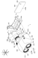
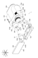
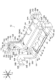
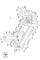
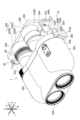
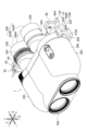
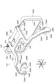
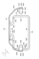
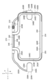
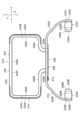
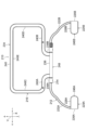
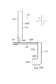
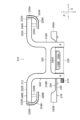
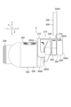
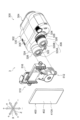
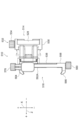
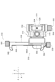
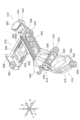
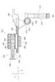
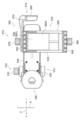
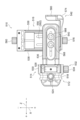
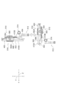
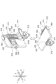
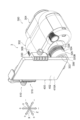
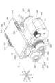
- FIG. 1 is a front side perspective view showing an example of an optical assembly and a smart phone according to a first embodiment
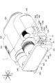
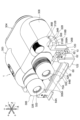
- FIG. FIG. 2 is a rear side perspective view showing an example of an optical assembly and a smart phone according to the first embodiment
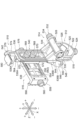
- It is a front side perspective view showing an example of an adapter concerning a 1st embodiment.
- It is a back side perspective view showing an example of an adapter concerning a 1st embodiment.
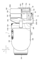
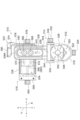
- It is a front view which shows an example of the adapter which concerns on 1st Embodiment.
- It is a rear view which shows an example of the adapter which concerns on 1st Embodiment.
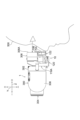
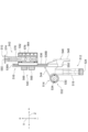
- FIG. 4 is a front side perspective view showing an example of a first observation mode of the optical assembly according to the first embodiment; FIG. FIG.
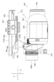
- FIG. 4 is a rear side perspective view showing an example of a first observation mode of the optical assembly according to the first embodiment; 4 is a right side view showing an example of a first observation mode of the optical assembly according to the first embodiment;
- FIG. FIG. 5 is a front side perspective view showing an example of a second observation mode of the optical assembly according to the first embodiment;
- FIG. 10 is a rear side perspective view showing an example of a second observation mode of the optical assembly according to the first embodiment;
- FIG. 5 is a rear view showing an example of a second observation mode of the optical assembly according to the first embodiment;
- FIG. 10 is a right side view showing an example of a second observation mode of the optical assembly according to the first embodiment;
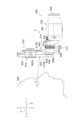
- FIG. 4 is a right side view showing an example of the usage state of the optical assembly according to the first embodiment in the first observation mode
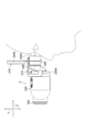
- FIG. 10 is a right side view showing an example of the usage state of the optical assembly according to the first embodiment in the second observation mode
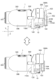
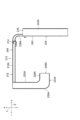
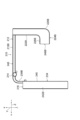
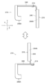
- FIG. 5 is a right side view showing an example of how the optical assembly according to the first embodiment is switched between the first observation mode and the second observation mode
- FIG. 11 is a front side perspective view showing an example of an optical assembly and a smart phone according to a second embodiment
- FIG. 11 is a rear side perspective view showing an example of an optical assembly and a smart phone according to a second embodiment
- It is a front side perspective view which shows an example of the adapter which concerns on 2nd Embodiment.
- FIG. 1 It is a back side perspective view which shows an example of the adapter which concerns on 2nd Embodiment. It is a front view which shows an example of the adapter which concerns on 2nd Embodiment. It is a rear view which shows an example of the adapter which concerns on 2nd Embodiment. It is a right view which shows an example of the adapter which concerns on 2nd Embodiment. It is a left view which shows an example of the adapter which concerns on 2nd Embodiment. It is a top view which shows an example of the adapter which concerns on 2nd Embodiment. It is a bottom view which shows an example of the adapter which concerns on 2nd Embodiment. FIG.
- FIG. 11 is a front side perspective view showing an example of a state in which the holding member is rotated to the second position in the adapter according to the second embodiment;
- FIG. 11 is a rear side perspective view showing an example of a state in which the holding member is rotated to the second position in the adapter according to the second embodiment;
- FIG. 10 is a front view showing an example of a state in which the holding member is rotated to the second position in the adapter according to the second embodiment;
- FIG. 10 is a rear view showing an example of a state in which the holding member is rotated to the second position in the adapter according to the second embodiment;
- FIG. 10 is a right side view showing an example of a state in which the holding member is rotated to the second position in the adapter according to the second embodiment;
- FIG. 10 is a front side perspective view showing an example of a state in which the holding member is rotated to the second position in the adapter according to the second embodiment;
- FIG. 11 is a rear side perspective view showing an example
- FIG. 10 is a left side view showing an example of a state in which the holding member is rotated to the second position in the adapter according to the second embodiment
- FIG. 11 is a plan view showing an example of a state in which the holding member is rotated to the second position in the adapter according to the second embodiment
- It is a bottom view which shows an example of the state which the holding member rotated to the 2nd position in the adapter which concerns on 2nd Embodiment.
- It is a right view which shows an example of a mode that a holding member moves to a 1st position and a 2nd position in the adapter which concerns on 2nd Embodiment.
- FIG. 11 is a front side perspective view showing an example of a first observation mode of the optical assembly according to the second embodiment;
- FIG. 11 is a front side perspective view showing an example of a first observation mode of the optical assembly according to the second embodiment
- FIG. 11 is a rear side perspective view showing an example of a first observation mode of the optical assembly according to the second embodiment;
- FIG. 11 is a right side view showing an example of the first observation mode of the optical assembly according to the second embodiment;
- FIG. 11 is a front side perspective view showing an example of a second observation mode of the optical assembly according to the second embodiment;
- FIG. 11 is a rear side perspective view showing an example of a second observation mode of the optical assembly according to the second embodiment;
- FIG. 10 is a right side view showing an example of a second observation mode of the optical assembly according to the second embodiment;
- FIG. 11 is a right side view showing an example of the usage state of the optical assembly according to the second embodiment in the first observation mode;
- FIG. 11 is a right side view showing an example of the usage state of the optical assembly according to the second embodiment in the second observation mode;
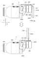
- FIG. 11 is a right side view showing an example of how the optical assembly according to the second embodiment is switched between the first observation mode and the second observation mode; It is a right side view showing the 1st modification of the optical assembly concerning a 2nd embodiment.
- FIG. 11 is a right side view showing a second modified example of the optical assembly according to the second embodiment;
- FIG. 11 is a front side perspective view showing an example of an optical assembly and a smart phone according to a third embodiment;
- 11 is a rear side perspective view showing an example of an optical assembly and a smart phone according to a third embodiment; It is a front side perspective view which shows an example of the adapter which concerns on 3rd Embodiment. It is a front side perspective view which shows an example of the adapter which concerns on 3rd Embodiment. It is a back side perspective view showing an example of an adapter concerning a 3rd embodiment. It is a back side perspective view showing an example of an adapter concerning a 3rd embodiment. It is a front view which shows an example of the adapter which concerns on 3rd Embodiment. It is a rear view which shows an example of the adapter which concerns on 3rd Embodiment.
- FIG. 1 It is a right side view showing an example of an adapter concerning a 3rd embodiment. It is a left view which shows an example of the adapter which concerns on 3rd Embodiment. It is a top view which shows an example of the adapter which concerns on 3rd Embodiment. It is a bottom view which shows an example of the adapter which concerns on 3rd Embodiment. It is a back side perspective view which shows an example of a state that a holding
- FIG. 11 is a front side perspective view showing an example of a state in which the holding portion of the adapter according to the third embodiment is rotated to the second position;
- FIG. 11 is a front side perspective view showing an example of a state in which the holding portion of the adapter according to the third embodiment is rotated to the second position;
- FIG. 11 is a rear side perspective view showing an example of a state in which the holding portion of the adapter according to the third embodiment is rotated to the second position;
- FIG. 11 is a front side perspective view showing an example of a state in which the holding portion of the adapter according to the third embodiment is rotated to the second position;
- 11 is a rear side perspective view showing an example of a state in which the holding portion of the adapter according to the third embodiment is rotated to the second position; It is a front view which shows an example of the state which the holding
- FIG. 11 is a plan view showing an example of a state in which the holding portion of the adapter according to the third embodiment is rotated to the second position; It is a bottom view which shows an example of the state which the holding
- FIG. 11 is a left side view showing an example of how a holding portion that holds a smart phone in an adapter according to a third embodiment rotates between a first position and a second position; FIG.
- FIG. 11 is a rear side perspective view showing an example of how a holding portion that holds a smart phone in an adapter according to a third embodiment rotates between a first position and a second position;
- FIG. 11 is a front side perspective view showing an example of how a holding portion that holds a smart phone in an adapter according to a third embodiment rotates between a first position and a second position;
- FIG. 12 is a front side perspective view showing an example of a first observation mode of the optical assembly according to the third embodiment;
- FIG. 12 is a rear side perspective view showing an example of a first observation mode of the optical assembly according to the third embodiment;
- FIG. 12 is a left side view showing an example of a first observation mode of the optical assembly according to the third embodiment;
- FIG. 12 is a front side perspective view showing an example of a second observation mode of the optical assembly according to the third embodiment;
- FIG. 12 is a rear side perspective view showing an example of a second observation mode of the optical assembly according to the third embodiment;
- FIG. 11 is a left side view showing an example of a second observation mode of the optical assembly according to the third embodiment;
- FIG. 11 is a left side view showing an example of the usage state of the optical assembly according to the third embodiment in the first observation mode;
- FIG. 12 is a left side view showing an example of the usage state of the optical assembly according to the third embodiment in the second observation mode;
- FIG. 14 is a left side view showing an example of how the optical assembly according to the third embodiment is switched between the first observation mode and the second observation mode;
- the optical assembly 1 includes binoculars 300 and an adapter 10 .
- Optical assembly 1 corresponds to a set of binoculars 300 and adapter 10 .
- the adapter 10 is a connection device that connects the smartphone 400 to the binoculars 300 as described later.
- the optical assembly 1 is an example of an "optical assembly” according to the technology of the present disclosure.
- the binoculars 300 are examples of the “first optical device” and the “binoculars” according to the technology of the present disclosure.
- the smartphone 400 is an example of the "second optical device” and the "imaging device” according to the technology of the present disclosure.
- the adapter 10 is an example of an "adapter” according to the technology of the present disclosure.
- the binoculars 300 are, for example, optical anti-vibration binoculars having anti-vibration functions.
- optical anti-vibration binoculars are given as an example of the binoculars 300, but this is only an example, and the binoculars 300 may be binoculars having any function.
- the binoculars 300 have a width direction, a height direction, and a length direction.
- the width direction, height direction, and length direction of the binoculars 300 are directions orthogonal to each other.
- the X direction indicates the width direction of the binoculars 300
- the Y direction indicates the height direction of the binoculars 300
- the Z direction indicates the length direction of the binoculars 300 .
- the width direction of the binoculars 300 is called the X direction
- the height direction of the binoculars 300 is called the Y direction
- the length direction of the binoculars 300 is called the Z direction.
- one side in the width direction of the binoculars 300 is called the X ⁇ side
- the other side in the width direction of the binoculars 300 is called the X+ side.
- One side of the binoculars 300 in the height direction is called the Y+ side
- the other side of the binoculars 300 in the height direction is called the Y ⁇ side.
- one side in the length direction of the binoculars 300 is called the Z+ side
- the other side in the length direction of the binoculars 300 is called the Z ⁇ side.
- the binoculars 300 include a main body 302 , an objective optical section 304 and an eyepiece optical section 306 .
- the main body 302 is an example of a "first main body” and a “second main body” according to the technology of the present disclosure.
- the objective optical section 304 is an example of the “objective optical section” according to the technology of the present disclosure.
- the eyepiece optical unit 306 is an example of the “eyepiece optical unit” according to the technology of the present disclosure.
- the objective optical section 304 and the eyepiece optical section 306 are arranged in the Z direction via the main body 302 .
- the objective optical section 304 is provided on the Z ⁇ side of the main body 302
- the eyepiece optical section 306 is provided on the Z+ side of the main body 302 .
- the Z ⁇ side of the binoculars 300 corresponds to the front end side of the binoculars 300
- the Z+ side of the binoculars 300 corresponds to the rear end side of the binoculars 300 .
- the binoculars 300 are binoculars having an objective optical section 304 on the front end side and an eyepiece optical section 306 on the rear end side.
- the main body 302 is a portion of the binoculars 300 located between the objective optical section 304 and the eyepiece optical section 306, and constitutes the main body portion of the binoculars 300.
- Body 302 has a housing 308 . Inside the housing 308, for example, an anti-vibration structure (not shown) that realizes an anti-vibration function is accommodated.
- the housing 308 is an example of a “housing” according to the technology of the present disclosure.
- a first hole 310A and a second hole 312A are formed in the X+ side and Z+ side corners of the housing 308 .
- the first hole 310A is a hole whose depth direction is the Z direction, and is open on the Z+ side.
- the second hole 312A is located on the X+ side and the Z- side with respect to the first hole 310A.
- the second hole 312A is a hole whose depth direction is the X direction, and is open on the X+ side.
- 310 A of 1st holes and 312 A of 2nd holes may each be formed in bag shape, and may be connected.
- the first hole 310A and the second hole 312A may be formed as strap holes for passing a strap (not shown).
- a first hole 310B and a second hole 312B are formed in the X-side and Z-side corners of the housing 308 .
- the first hole 310B and the second hole 312B are formed in plane symmetry with the first hole 310A and the second hole 312A in the X direction.
- the first holes 310A and 310B are referred to as the first holes 310, respectively.
- the second holes 312A and 312B are referred to as the second holes 312, respectively.
- the objective optical section 304 is an optical device having an objective lens section 314A and an objective lens section 314B.
- the objective lens section 314A and the objective lens section 314B are arranged in the X direction.
- the objective lens section 314A and the objective lens section 314B will be referred to as the objective lens section 314 when the objective lens section 314A and the objective lens section 314B are not distinguished from each other.
- Each objective lens section 314 has an objective lens 316 and a lens barrel 318 .
- the objective lens 316 is provided inside the barrel 318 and supported by the barrel 318 .
- a lens barrel 318 is connected to the housing 308 .
- the objective optical section 304 is supported by the main body 302 by connecting each lens barrel 318 to the housing 308 .
- the eyepiece optical unit 306 is an optical device having an eyepiece lens unit 320A and an eyepiece lens unit 320B.
- the eyepiece part 320A and the eyepiece part 320B are arranged in the X direction.
- the eyepiece units 320A and 320B will be referred to as eyepiece units 320, respectively, when the eyepiece units 320A and 320B are not distinguished from each other.
- Each eyepiece section 320 has an eyepiece 322 , a lens barrel 324 and a protective member 326 .
- the eyepiece 322 is provided inside the lens barrel 324 and supported by the lens barrel 324 .
- Each lens barrel 324 is connected to the housing 308 .
- Each protection member 326 is, for example, a rubber ring, and is fixed to the Z+ side end of the lens barrel 324 .
- the eyepiece optical unit 306 is supported by the main body 302 by connecting each lens barrel 324 to the housing 308 .
- a diopter adjustment ring 328 for adjusting the diopter of the binoculars 300 is provided in the lens barrel 324 of the eyepiece lens section 320B arranged on the X- side of the eyepiece lens sections 320A and 320B. Also, the main body 302 is provided with a power button 330 for switching the power of the binoculars 300 between on and off. Further, the body 302 is provided with a focus adjustment dial 332 for adjusting focus.
- the smartphone 400 is formed in a rectangular plate shape when viewed from the front.
- a smartphone 400 includes a touch panel display 402 , a camera 404 and a connector 406 .
- Touch panel display 402 is provided entirely on front surface 410A of smartphone 400
- camera 404 is provided in the upper corner of rear surface 410B of smartphone 400 .
- the back surface 410B is the surface opposite to the front surface 410A.
- the camera 404 may be provided flush with the rear surface 410B, or may protrude from the rear surface 410B. Also, the camera 404 may be provided at a recessed position with respect to the back surface 410B. In the example shown in FIGS. 1 and 2, camera 404 protrudes from back surface 410B, as an example.
- the connector 406 is formed in a concave shape and provided on the lower surface 410C of the smartphone 400.
- the connector 406 is, for example, a connector conforming to standards such as USB (Universal Serial Bus) or Lightning.
- the back surface 410B is an example of the "first surface” according to the technology of the present disclosure.
- the front surface 410A is an example of the "third surface” according to the technology of the present disclosure.
- the adapter 10 includes a fixed member 12, a slide mechanism 14, a first movable member 16, a second movable member 18, a third movable member 20, and a holding member 22.
- the fixing member 12 has a base portion 24, arm portions 26A, and arm portions 26B.
- the base portion 24 is formed in a plate shape with the Y direction as the plate thickness direction, and extends in the X direction.
- the arm portion 26A is formed at the X+ side end of the base portion 24, and the arm portion 26B is formed at the X ⁇ side end of the base portion 24. As shown in FIG. Both the arm portion 26A and the arm portion 26B extend from the base portion 24 toward the Y+ side.
- the arm portion 26B is formed symmetrically with the arm portion 26A in the X direction. Arms 26A and 26B are examples of "arms" according to the technology of the present disclosure.
- a grip portion 28A is formed at the tip of the arm portion 26A.
- the grip portion 28A has a body portion 30A, a plate spring portion 32A, a first convex portion 34A, and a second convex portion 36A.
- the body portion 30A extends from the tip portion of the arm portion 26A to the X+ side.
- the first convex portion 34A protrudes from the X ⁇ side end of the main body portion 30A toward the Z ⁇ side.
- the plate spring portion 32A extends from the X+ side end of the main body portion 30A to the Z ⁇ side.
- the plate spring portion 32A is formed in a plate shape with the X direction as the plate thickness direction.
- the second convex portion 36A protrudes from the tip of the plate spring portion 32A toward the X ⁇ side.
- a grip portion 28B is formed at the tip of the arm portion 26B.
- the grip portion 28B has a main body portion 30B, a leaf spring portion 32B, a first convex portion 34B, and a second convex portion 36B.
- the gripping portion 28B is formed symmetrically with the gripping portion 28A in the X direction.
- the grip portion 28A and the grip portion 28B are referred to as the grip portion 28, respectively. Referred to as arm 26 .
- the slide mechanism 14 has a guide member 38 and a slide member 40 .
- the guide member 38 is provided on the Y+ side surface of the base portion 24 and fixed to the base portion 24 .
- the guide member 38 has a pair of guide rails 42 .
- the pair of guide rails 42 are separated in the X direction.
- Each guide rail 42 extends in the Z direction.
- the slide member 40 is slidably supported in the Z direction by a pair of guide rails 42 .
- the first movable member 16 is arranged on the Y+ side with respect to the slide member 40 .
- the first movable member 16 is fixed to the slide member 40 with a plurality of bolts 44 and a plurality of nuts 46 (see FIG. 10).
- the first movable member 16 has a first plate-shaped portion 48 .
- the first plate-like portion 48 is formed in a plate shape with the Y direction as the plate thickness direction, and extends in the X direction.
- the second movable member 18 is arranged on the Y+ side with respect to the first movable member 16 .
- the first movable member 16 has a second plate-shaped portion 50 .
- the second plate-shaped portion 50 is formed in a plate shape with the Y direction as the plate thickness direction, and extends in the X direction.
- the second plate-shaped portion 50 overlaps the first plate-shaped portion 48 in the Y direction.
- the third movable member 20 is arranged on the Y+ side with respect to the second movable member 18 .
- the third movable member 20 has a third plate-shaped portion 52, an erected wall portion 54A, an erected wall portion 54B, a fourth plate-shaped portion 56A, and a fourth plate-shaped portion 56B.
- the third plate-shaped portion 52 is formed in a plate shape with the Y direction as the plate thickness direction, and extends in the X direction.
- the third plate-shaped portion 52 overlaps the second plate-shaped portion 50 in the Y direction.
- the vertical wall portion 54A is formed at the X+ side end of the third plate-shaped portion 52, and the vertical wall portion 54B is formed at the X- side end of the third plate-shaped portion 52.
- the vertical wall portion 54A and the vertical wall portion 54B are both formed in a plate shape with the X direction as the thickness direction.
- the standing wall portion 54A and the standing wall portion 54B extend from the third plate-shaped portion 52 toward the Y+ side.
- the vertical wall portions 54A and 54B are referred to as vertical wall portions 54, respectively.
- the fourth plate-shaped portion 56A is formed at the Z+ side end of the vertical wall portion 54A, and the fourth plate-shaped portion 56A is formed at the Z+ side end of the vertical wall portion 54B.
- the fourth plate-shaped portion 56A extends from the standing wall portion 54A toward the X+ side
- the fourth plate-shaped portion 56B extends from the standing wall portion 54B toward the X ⁇ side.
- Each of the fourth plate-shaped portion 56A and the fourth plate-shaped portion 56B is formed in a plate-like shape with the Z direction as the plate thickness direction, and extends in the Y direction.
- the fourth plate-shaped portion 56A and the fourth plate-shaped portion 56B are referred to as the fourth plate-shaped portion 56, respectively.
- the holding member 22 is arranged on the Z+ side with respect to the third movable member 20 .
- the holding member 22 has a front wall portion 58, a rear wall portion 60, side wall portions 62, a bottom wall portion 64A, and a bottom wall portion 64B.
- the front wall portion 58 is formed in a plate shape with the Z direction as the plate thickness direction, and extends in the X direction.
- the front wall portion 58 overlaps each fourth plate portion 56 in the Z direction.
- the rear wall portion 60 is provided on the Z+ side with respect to the X ⁇ side end of the front wall portion 58 .
- the rear wall portion 60 is formed in a plate shape with the Z direction as the plate thickness direction, and extends in the Y direction.
- the rear wall 60 is spaced apart from the front wall 58 in the Z direction and faces the X ⁇ side end of the front wall 58 .
- the side wall portion 62 is formed in a plate shape with the X direction as the plate thickness direction, and extends in the Y direction.
- the side wall portion 62 connects the X ⁇ side end of the front wall portion 58 and the X ⁇ side end of the rear wall portion 60 .
- a first groove 66 is formed in the side wall portion 62 .
- the first groove 66 extends in the Y direction and opens on the Y+ side. The first groove 66 penetrates in the X direction.
- the bottom wall portion 64A and the bottom wall portion 64B are formed at the end of the front wall portion 58 on the Y ⁇ side. Both the bottom wall portion 64A and the bottom wall portion 64B extend from the front wall portion 58 toward the Z+ side. Both the bottom wall portion 64A and the bottom wall portion 64B are formed in a plate shape with the Y direction as the plate thickness direction, and extend in the X direction. The bottom wall portion 64A and the bottom wall portion 64B are formed apart in the X direction. The bottom wall portion 64A is located on the X+ side with respect to the bottom wall portion 64B. A second groove 68 penetrating in the Y direction is formed between the bottom wall portion 64A and the bottom wall portion 64B.
- the Z+ side surface of the front wall portion 58 is formed as a first holding surface 70A
- the Z ⁇ side surface of the rear wall portion 60 is formed as a second holding surface 70B
- the X+ side surface of the side wall portion 62 is formed as a third holding surface 70C
- the Y+ side surfaces of the bottom wall portion 64A and the bottom wall portion 64B are formed as a fourth holding surface 70D and a fourth holding surface, respectively.
- 70E A picture 72 representing smartphone 400 and an arrow 74 indicating the insertion direction of smartphone 400 are shown at the X+ side end of first holding surface 70A.
- the adapter 10 also includes a pair of first adjustment mechanisms 76, a pair of second adjustment mechanisms 78, a plurality of third adjustment mechanisms 80, and a positioning mechanism 82.
- the pair of first adjustment mechanisms 76, the pair of second adjustment mechanisms 78, and the plurality of third adjustment mechanisms 80 constitute an adjustment mechanism 84 (that is, adjusters).
- the adjustment mechanism 84 is an example of the "adjustment mechanism” according to the technology of the present disclosure.
- the positioning mechanism 82 is an example of a "positioning mechanism" according to the technology of the present disclosure.
- the pair of first adjustment mechanisms 76 are separated in the X direction. Each first adjustment mechanism 76 has a first slot 86 , a first bolt 88 and a first nut 90 .
- the first long hole 86 is formed in the second plate-shaped portion 50 .
- the first long hole 86 is a long hole extending in the X direction.
- a first communication hole (not shown) that communicates with the first long hole 86 is formed in the first plate-like portion 48 .
- the shaft of the first bolt 88 is inserted from the Y- side into the first communication hole and the first elongated hole 86, and a first nut 90 is screwed to the tip of the shaft of the first bolt 88. ing.
- the first plate-shaped portion 48 and the second plate-shaped portion 50 are fixed by a first bolt 88 and a first nut 90 .
- first nut 90 is loosened with respect to the first bolt 88
- the second movable member 18 moves to the first movable position within the range in which the shaft portion of the first bolt 88 relatively moves within the first elongated hole 86 . It is possible to move in the X direction with respect to member 16 .
- the pair of second adjustment mechanisms 78 are separated in the X direction.
- Each second adjustment mechanism 78 has a second slot 92 , a second bolt 94 and a second nut 96 .
- the second long hole 92 is formed in the third plate-shaped portion 52 .
- the second long hole 92 is a long hole extending in the Z direction.
- a second communication hole (not shown) that communicates with the second long hole 92 is formed in the second plate-like portion 50 .
- the shaft of the second bolt 94 is inserted from the Y- side into the second communication hole and the second elongated hole 92, and a second nut 96 is screwed onto the tip of the shaft of the second bolt 94. ing.
- the second plate-shaped portion 50 and the third plate-shaped portion 52 are fixed by a second bolt 94 and a second nut 96 .
- the third movable member 20 moves to the second movable position within the range in which the shaft portion of the second bolt 94 relatively moves within the second elongated hole 92 . It is possible to move in the Z direction with respect to member 18 .
- the plurality of third adjustment mechanisms 80 are provided on the fourth plate-shaped portion 56A and the fourth plate-shaped portion 56B, respectively.
- Each third adjustment mechanism 80 has a third slot 98 , a third bolt 100 and a third nut 102 .
- a third slot 98 is formed in the fourth plate-shaped portion 56 .
- the third long hole 98 is a long hole extending in the Y direction.
- a third communication hole (not shown) communicating with the third long hole 98 is formed in the front wall portion 58 .
- the shaft of the third bolt 100 is inserted from the Z ⁇ side into the third elongated hole 98 and the third communication hole, and a third nut 102 is screwed to the tip of the shaft of the third bolt 100. ing.
- the fourth plate-shaped portion 56 and the front wall portion 58 are fixed by a third bolt 100 and a third nut 102 .
- the holding member 22 moves toward the third movable member 20 within a range in which the shaft portion of the third bolt 100 relatively moves within the third elongated hole 98 . It is possible to move in the Y direction with respect to .
- the positioning mechanism 82 has a pair of opposing wall portions 104 , a connecting wall portion 106 , a positioning pin 108 , a fourth bolt 110 and a fourth nut 112 .
- a pair of opposing wall portions 104 extend from the side wall portion 62 to the X ⁇ side. The pair of opposing walls 104 are opposed in the Z direction. A pair of opposing walls 104 are formed on both sides of the first groove 66 in the Z direction. The Y ⁇ side ends of the pair of opposing wall portions 104 are connected by a connecting wall portion 106 .
- a third groove 114 is formed between the pair of opposing wall portions 104 . The third groove 114 extends in the Y direction and opens on the Y+ side.
- the third groove 114 penetrates in the X direction and communicates with the first groove 66 .
- a bottom side portion of the third groove 114 is formed as a through hole 116 extending in the X direction.
- the through hole 116 penetrates in the X direction and communicates with the first groove 66 .
- the positioning pin 108 is inserted into the first groove 66 and the through hole 116.
- a tip portion 108 A of the positioning pin 108 protrudes from the side wall portion 62 between the front wall portion 58 and the rear wall portion 60 .
- a base end portion 108B of the positioning pin 108 is inserted into the through hole 116 .
- a shaft portion of a fourth bolt 110 passes through the pair of opposing wall portions 104 in the Z direction, and a fourth nut 112 is screwed to the tip portion of the shaft portion of the fourth bolt 110 .
- the positioning pin 108 is fixed to the holding member 22 by being gripped by the pair of opposing walls 104 .
- the positioning pin 108 is released from the gripping state of the positioning pin 108 by the pair of opposing wall portions 104, and the positioning pin 108 is moved in the X direction with respect to the holding member 22. Is possible.
- the arm portion 26A and the grip portion 28A constitute a fixed portion 118A
- the arm portion 26B and the grip portion 28B constitute a fixed portion 118B
- the fixed portions 118A and 118B will be referred to as fixed portions 118, respectively.
- the base portion 24 and the slide mechanism 14 constitute a support portion 120 .
- the first movable member 16, the second movable member 18, the third movable member 20, and the holding member 22 constitute a holding portion 122 (that is, a holder).
- the holding portion 122 is supported by the support portion 120 so as to be slidable in the Z direction with respect to each fixed portion 118 .
- a convex portion 124 is formed on the Y+ side surface of the third plate-shaped portion 52 included in the holding portion 122 .
- the convex portion 124 functions as a finger rest portion for putting a finger on when the user slides the holding portion 122 with respect to each fixing portion 118 in the Z direction.
- the fixed part 118 is an example of a "fixed part” according to the technology of the present disclosure.
- the support portion 120 is an example of a “support portion” according to the technology of the present disclosure.
- the holding portion 122 is an example of a “holding portion” according to the technology of the present disclosure.
- the holding portion 122 is slidably supported by the support portion 120 between the first position and the second position.
- the first position is the position shown in the upper diagram of FIG. 11, and the second position is the position shown in the lower diagram of FIG.
- the first position is the position when the holding portion 122 slides to the first end on the Z+ side in the movable range (that is, the sliding range), and the second position is the position where the holding portion 122 slides to the Z ⁇ side in the movable range. is the position when slid to the second end of the .
- the first end and the second end of the movable range of the holding part 122 are defined, for example, by providing the slide mechanism 14 with a stopper structure and/or a check mechanism (both not shown).
- the first position is an example of a "first position" according to the technology of the present disclosure
- the second position is an example of a "second position” according to the technology of the present disclosure. 1 to 10 described above show a state in which the holding portion 122 has slid to the first position.
- the arm portion 26A and the arm portion 26B are provided outside the space in which the holding portion 122 slides with respect to each fixing portion 118 .
- the space in which the holding portion 122 slides with respect to each fixed portion 118 is a space through which the holding portion 122 passes when the holding portion 122 slides between the first position and the second position (that is, a three-dimensional space). region).
- the arm portion 26A and the arm portion 26B are located outside the position where the holding portion 122 interferes with the holding portion 122 when the holding portion 122 slides between the first position and the second position. provided in a non-interfering area).
- the arm portion 26A is provided on the X+ side with respect to the first plate-shaped portion 48, the second plate-shaped portion 50, and the third plate-shaped portion 52 when viewed in the Z direction.
- 26B is provided on the X ⁇ side with respect to the first plate-shaped portion 48, the second plate-shaped portion 50, and the third plate-shaped portion 52 when viewed from the Z direction (see also FIGS. 3 to 6). .
- the arm portions 26A and 26B are positioned so that a gap in the Z direction is created between the arm portions 26A and 26B and the fourth plate-shaped portion 56 when the holding portion 122 slides to the first position.
- a space in which the holding portion 122 slides with respect to each fixing portion 118 is an example of the “space” according to the technology of the present disclosure.
- each fixing part 118 is fixed to the binoculars 300.
- each fixed part 118 is fixed to the housing 308 of the binoculars 300 .
- the first protrusion 34 is fitted in the first hole 310 and the second protrusion 36 is fitted in the second hole 312 .
- the portion between the first hole 310 and the second hole 312 in the housing 308 is gripped by the first protrusion 34 and the second protrusion 36 .
- the main body portion 30 and the arm portion 26 are examples of the "first contact portion" according to the technology of the present disclosure.
- each fixing portion 118 When each fixing portion 118 is fixed to the housing 308, each first convex portion 34 is fitted into the first hole 310, so that the adapter 10 is prevented from moving in the X direction and the Y direction with respect to the housing 308. Limited. Further, by fitting the second protrusions 36 into the second holes 312 respectively, movement of the adapter 10 in the Y and Z directions with respect to the housing 308 is restricted.
- FIGS. 12 to 14 show a state in which the holding portion 122 has slid to the first position.
- the first holding surface 70A is located on the Z+ side of the rear end surface 306A of the eyepiece optical portion 306 .
- smartphone 400 can be held by holding portion 122 .
- the smartphone 400 is placed on the bottom wall portion 64A from the X+ side in a sideways state, and is placed on the bottom wall portions 64A and 64B on the X- slide to the side.
- a lower end portion of the smartphone 400 is inserted between the front wall portion 58 and the rear wall portion 60 .
- the smartphone 400 is inserted between the front wall portion 58 and the rear wall portion 60 with the rear surface 410B facing the Z ⁇ side.
- Bottom wall portion 64B functions as a guide wall that guides smartphone 400
- bottom wall portion 64A functions as a rotation prevention wall that restricts rotation of smartphone 400 in the Z direction.
- a button (not shown) provided on the side surface of the smartphone 400 is inserted into the second groove 68 formed between the bottom wall portion 64A and the bottom wall portion 64B.
- the rear surface 410B of the smartphone 400 faces the first holding surface 70A.
- the first holding surface 70A may come into contact with the back surface 410B of the smart phone 400 .
- the front surface 410A of the smartphone 400 faces the second holding surface 70B.
- the second holding surface 70B may come into contact with the front surface 410A of the smart phone 400 .
- Smartphone 400 is thus held by holding section 122 .
- the back surface 410B of the smartphone 400 is an example of the "first surface” according to the technology of the present disclosure
- the first holding surface 70A is an example of the "second surface” and the "contact surface” according to the technology of the present disclosure. be.
- the front surface 410A of the smartphone 400 is an example of the "third surface” according to the technology of the present disclosure
- the second holding surface 70B is an example of the "fourth surface” according to the technology of the present disclosure.
- the optical assembly when the adapter 10 is fixed to the binoculars 300, the holding portion 122 is slid to the first position, and the smartphone 400 is held by the holding portion 122 1 is referred to as a first observation mode.
- the first holding surface 70A is located on the Z+ side of the rear end surface 306A of the eyepiece optical unit 306, and the rear surface 410B of the smartphone 400 faces the rear end surface 306A of the eyepiece optical unit 306 in the Z direction.
- the rear end surface 306A of the eyepiece optical unit 306 is an example of the "rear end surface of the eyepiece optical unit" according to the technology of the present disclosure.
- the rear end face 306A of the eyepiece optical section 306 is formed by the protective member 326.
- the rear end surface 306A of the eyepiece optical section 306 may be formed by the lens barrel 324 when the protective member 326 is omitted from the eyepiece optical section 306 .
- the rear end surface 306A of the eyepiece optical section 306 may be formed by members and/or parts provided in the eyepiece optical section 306 other than the protective member 326 and the lens barrel 324 .
- the camera 404 provided on the back surface 410B of the smartphone 400 detects the rear end surface 306A of the eyepiece optical unit 306 (for example, the eyepiece unit 320A located on the X+ side of the pair of eyepiece units 320). (rear end surface of ).
- the state in which the camera 404 faces the rear end surface 306A of the eyepiece optical section 306 corresponds to, for example, the state in which the camera 404 faces the rear end surface 306A of the eyepiece optical section 306 as viewed in the X direction.
- the camera 404 faces the rear end surface 306A of the eyepiece optical section 306, the eyepiece lens 322 of the eyepiece section 320A located on the X+ side of the pair of eyepiece sections 320 faces the camera 404, and the eyepiece lens 322 The light that passes through enters camera 404 .
- the camera 404 is an example of an “incident portion” and an “observation portion” according to the technology of the present disclosure.
- the smartphone 400 is positioned with respect to the eyepiece optical unit 306 by fitting the tip 108A of the positioning pin 108 into the connector 406 .
- the tip portion 108A of the positioning pin 108 is formed into a shape that fits into the connector 406.
- the smartphone 400 is positioned with respect to the eyepiece optical unit 306 in the X direction, the Y direction, and the Z direction.
- the front wall 58 and the rear wall 60 hold the smartphone 400 in the Z direction. This reduces the load acting on the connector 406 compared to, for example, the case where the smartphone 400 is not held in the Z direction by the front wall portion 58 and the rear wall portion 60 .
- FIGS. 15 to 18 show a state in which the smartphone 400 is removed from the holding portion 122 and the holding portion 122 is slid to the second position.
- the usage pattern of the optical assembly 1 when the adapter 10 is fixed to the binoculars 300 and the holder 122 is slid to the second position will be referred to as a second observation pattern.
- the first holding surface 70A is located on the Z ⁇ side (that is, on the objective optical section 304 side) of the rear end surface 306A of the eyepiece optical section 306 .
- the second holding surface 70B is also located on the Z ⁇ side (that is, on the objective optical section 304 side) of the rear end surface 306A of the eyepiece optical section 306 .
- the Z+ side surface 60A of the rear wall portion 60 is arranged on the Z+ side of the rear end surface 306A of the eyepiece optical portion 306. It may be arranged on the Z ⁇ side of the rear end face 306A of the eyepiece optical section 306 . That is, when the holding portion 122 slides to the second position, the rear wall portion 60 may be arranged on the Z ⁇ side of the rear end surface 306A.
- a frame line 334 surrounding the eyepiece optical unit 306 is shown in FIG.
- the area inside the frame line 334 is an overlap area that overlaps the eyepiece optical unit 306 when viewed from the optical axis direction of the eyepiece optical unit 306 (that is, the Z direction), and the area outside the frame line 334 is the eyepiece optical unit 306 is a non-overlapping area that does not overlap with the eyepiece optical unit 306 when viewed from the optical axis direction.
- the area inside the frame line 334 is an example of the "first area” and the "third area” according to the technology of the present disclosure, and the area outside the frame line 334 is the "second area” according to the technology of the present disclosure. ” and “fourth region”.
- the front wall portion 58 provided in the holding portion 122 is provided outside the frame line 334 (that is, non-overlapping area) when viewed from the optical axis direction of the eyepiece optical portion 306 . That is, the front wall portion 58 is formed with a notch portion 126 at a position overlapping the eyepiece optical portion 306 when viewed from the optical axis direction of the eyepiece optical portion 306 (that is, the Z direction).
- the structure is such that the front wall portion 58 is prevented from interfering with the eyepiece optical portion 306 as the lens 122 slides to the second position.
- the notch 126 extends in the X direction and has a shape cut from the Y+ side.
- the front wall portion 58 is an example of the “second wall portion” according to the technology of the present disclosure.
- the rear wall portion 60 is also provided outside the frame line 334 (ie, non-overlapping area) when viewed from the optical axis direction of the eyepiece optical portion 306 . Also, the rear wall portion 60 is located on the X ⁇ side of the notch portion 126 when viewed from the optical axis direction of the eyepiece optical portion 306 . Further, the side surface 60B on the X+ side of the rear wall portion 60 is formed by a curved surface in which the upper portion 60B1 is positioned closer to the X ⁇ side than the lower portion 60B2, and the lower portion 60B2 is curved toward the X ⁇ side as the lower portion 60B2 moves toward the Y+ side.
- the rear wall portion 60 is configured to avoid interference with the nose or cheeks of the user looking into the eyepiece optical portion 306 when the optical assembly 1 is in the second observation mode.
- the rear wall portion 60 is an example of the “first wall portion” according to the technology of the present disclosure.
- Smartphone 400 is held by holding portion 122 while holding portion 122 is slid to the first position. Further, the smartphone 400 is positioned with respect to the eyepiece optical unit 306 by fitting the tip portion 108A of the positioning pin 108 into the connector 406 .
- the smartphone 400 is held by the holding portion 122 , the eyepiece lens 322 of the eyepiece portion 320 ⁇ /b>A positioned on the X+ side of the pair of eyepiece portions 320 faces the camera 404 .
- the adjustment mechanism 84 adjusts the position of the smartphone 400 with respect to the eyepiece optical unit 306 in at least one of the X direction and the Y direction, so that the first optical axis A1 and the second optical axis A2 can be aligned. It is possible. Also, for example, by adjusting the position of the camera 404 with respect to the eyepiece optical unit 306 in the Z direction by the adjusting mechanism 84, the distance between the eyepiece lens 322 and the camera 404 can be adjusted.
- the Z direction is an example of the "first direction” according to the technology of the present disclosure.
- the X direction and the Y direction are examples of the "second direction crossing the first direction” according to the technology of the present disclosure.
- the first optical axis A1 is an example of a "first optical axis” according to the technology of the present disclosure.
- the second optical axis A2 is an example of a "second optical axis” according to the technology of the present disclosure.
- distal end portion 108A of positioning pin 108 is fitted into connector 406 so that first optical axis A1 and second optical axis A1 are aligned.
- Smartphone 400 is positioned at a position aligned with optical axis A2.
- smartphone 400 is positioned at a position that maintains the distance between eyepiece 322 and camera 404 .
- Holding portion 122 slides from the first position to the second position while smartphone 400 is removed from holding portion 122 .
- the first holding surface 70A is located on the Z ⁇ side (that is, on the objective optical portion 304 side) of the rear end surface 306A of the eyepiece optical portion 306 .
- the second holding surface 70B is also located on the Z ⁇ side (that is, on the objective optical section 304 side) of the rear end surface 306A of the eyepiece optical section 306 . Therefore, as shown in FIG. 20 as an example, in the second observation mode, projection of the holding portion 122 toward the Z+ side is suppressed as compared with the first observation mode. Therefore, the user 500 can directly look into the eyepiece optical section 306 .
- the adapter 10 includes a pair of fixing portions 118 fixed to the binoculars 300 , a holding portion 122 holding the smartphone 400 , and the holding portions 122 attached to each fixing portion 118 .
- a support portion 120 is provided for slidably supporting the first position and the second position.
- the first position is a position where the rear surface 410B of the smartphone 400 held by the holding portion 122 faces the rear end surface 306A of the eyepiece optical unit 306, and the holding portion 122 has a first holding surface 70A that faces the rear surface 410B.
- the second position is a position where the first holding surface 70A is arranged on the Z ⁇ side (that is, on the objective optical section 304 side) of the rear end surface 306A.
- the user 500 is more likely to see the eyepiece optical section 306 than when the first holding surface 70A is arranged on the Z+ side of the rear end surface 306A.
- the user can look into the eyepiece optical unit 306 in a state close to .
- the binoculars 300 also include a main body 302 that supports an objective optical section 304 and an eyepiece optical section 306 , and each fixing section 118 is fixed to the main body 302 . Therefore, for example, compared to the case where each fixed portion 118 is fixed to the lens barrel 324, it is possible to easily avoid interference between the holding portion 122 and each fixed portion 118 in terms of design.
- Each fixing part 118 has an arm part 26 extending from the supporting part 120 , and the arm part 26 is provided outside the space in which the holding part 122 slides with respect to each fixing part 118 . Therefore, arm portion 26 can be prevented from interfering with holding portion 122 .
- the smartphone 400 also has a front surface 410A opposite to the back surface 410B, and the holding portion 122 has a second holding surface 70B facing the front surface 410A.
- the second position is a position where the second holding surface 70B is arranged on the Z ⁇ side (that is, on the objective optical section 304 side) of the rear end surface 306A. Therefore, for example, when the holding portion 122 is moved to the second position, the holding portion 122 is positioned closer to the rear end surface 306A than when the second holding surface 70B is arranged on the Z+ side of the rear end surface 306A. Projection to the Z+ side can be suppressed.
- the holding portion 122 has a front wall portion 58 on which the first holding surface 70A is formed. It is provided in a non-overlapping region that is out of the overlapping region that overlaps the eye optic 306 . Therefore, it is possible to prevent the front wall portion 58 from interfering with the eyepiece optical portion 306 as the holding portion 122 slides to the second position.
- the holding portion 122 has a rear wall portion 60 on which the second holding surface 70B is formed. It is provided in a non-overlapping region that is out of the overlapping region that overlaps the eye optic 306 . Therefore, it is possible to prevent the rear wall portion 60 from interfering with the eyepiece optical portion 306 as the holding portion 122 slides to the second position.
- a notch 126 is formed in the front wall portion 58 at a position overlapping the eyepiece optical portion 306 when viewed from the optical axis direction of the eyepiece optical portion 306 (that is, the Z direction). It is located on the X ⁇ side of the notch 126 when viewed from the optical axis direction of the eye optical part 306 . Further, the side surface 60B on the X+ side of the rear wall portion 60 is formed by a curved surface in which the upper portion 60B1 is positioned closer to the X ⁇ side than the lower portion 60B2, and the lower portion 60B2 is curved toward the X ⁇ side as the lower portion 60B2 moves toward the Y+ side. Therefore, it is possible to prevent the nose or cheeks of the user 500 looking into the eyepiece optical section 306 from interfering with the rear wall section 60 when the optical assembly 1 is in the second observation mode.
- the support portion 120 supports the holding portion 122 slidably with respect to each fixing portion 118 . Therefore, for example, without removing the adapter 10 from the binoculars 300, by sliding the holding portion 122, the mode of use of the optical assembly 1 can be switched between the first observation mode and the second observation mode.
- Each fixing part 118 has a gripping part 28 and an arm part 26
- the gripping part 28 has a main body part 30 .
- the body portion 30 and the arm portion 26 abut against the binoculars 300 in the direction in which the holding portion 122 slides relative to each fixed portion 118 (that is, the Z direction). Therefore, when the holding portion 122 is slid to the Z ⁇ side with respect to each fixing portion 118, the posture of the adapter 10 can be stabilized.
- the adapter 10 further includes an adjustment mechanism 84 that adjusts the position of the smartphone 400 with respect to the eyepiece optical section 306. Therefore, for example, when the first optical axis A1, which is the optical axis of the eyepiece optical unit 306, and the second optical axis A2, which is the optical axis of the camera 404, are deviated from each other, the adjusting mechanism 84 adjusts the smartphone to the eyepiece optical unit 306. By adjusting the position of 400, the first optical axis A1 and the second optical axis A2 can be aligned.
- the adjustment mechanism 84 also adjusts the position of the smartphone 400 in the Z direction, which is the direction in which the holding portion 122 slides relative to each fixing portion 118, and in the X and Y directions that intersect the Z direction. Therefore, for example, compared to the case where the smartphone 400 can be adjusted in only one direction with respect to the eyepiece optical unit 306, the degree of freedom in adjusting the position of the smartphone 400 can be increased.
- the adapter 10 further includes a positioning mechanism 82 that positions the smartphone 400 with respect to the eyepiece optical section 306. Therefore, it is possible to suppress displacement of the smartphone 400 held by the holding portion 122 as compared with the case where the positioning mechanism 82 is not provided. Further, when the position of the smartphone 400 with respect to the eyepiece optical unit 306 is adjusted by the adjustment mechanism 84, even if the smartphone 400 is repeatedly attached to and detached from the holding unit 122, the position of the smartphone 400 with respect to the eyepiece optical unit 306 is maintained. be able to.
- the smartphone 400 also has a camera 404 that faces the rear end surface 306A and receives light that has passed through the eyepiece optical unit 306.
- the positioning mechanism 82 has a first optical axis A1 and a second optical axis A2.
- the smartphone 400 is positioned at the alignment position. Therefore, it is possible to suppress deviation between the first optical axis A1 and the second optical axis A2 as compared with the case where the positioning mechanism 82 is not provided.
- the adapter 10 is fixed to the binoculars 300 . Therefore, smartphone 400 can be attached to binoculars 300 .
- the smart phone 400 also has a camera 404 . Therefore, by capturing an image of the subject with the camera 404 through the binoculars 300, it is possible to obtain an enlarged image compared to the case of directly capturing the image of the subject with the smartphone 400.
- FIG. 1 A schematic diagram illustrating an image of the subject with the smartphone 400.
- the adapter 10 is fixed to the binoculars 300 in the first embodiment, it may be fixed to an optical device other than the binoculars 300, such as a microscope or a telescope. Also, any number of objective lens units 314 and eyepiece lens units 320 may be provided in the optical device to which the adapter 10 is fixed.
- Both the objective optical section 304 and the eyepiece optical section 306 are supported by the main body 302 , but one of the objective optical section 304 and the eyepiece optical section 306 may be supported by a part different from the main body 302 .
- the adapter 10 holds the smart phone 400, but in addition to the smart phone 400, it may hold an imaging device such as a tablet terminal or a digital camera. Also, the adapter 10 may hold an optical device other than the imaging device.
- the camera 404 faces the rear end surface 306A, but in addition to the camera 404, an observation section including an optical system may face the rear end surface 306A. Also, the tip of the observation unit may protrude from the rear surface 410B or may be provided at a position recessed from the rear surface 410B.
- the light that has passed through the eyepiece optical unit 306 enters the camera 404, but the light that has passed through the eyepiece optical unit 306 may enter an incident portion having an optical system other than the camera 404.
- the tip of the incident portion may protrude from the back surface 410B or may be provided at a position recessed from the back surface 410B.
- the back surface 410B of the smartphone 400 faces the rear end surface 306A of the eyepiece optical unit 306, but a surface other than the rear surface 410B may face the rear end surface 306A of the eyepiece optical unit 306.
- the first holding surface 70A of the holding portion 122 faces the back surface 410B of the smartphone 400, but a surface other than the back surface 410B may face the first holding surface 70A.
- the second holding surface 70B of the holding portion 122 faces the front surface 410A of the smartphone 400, but a surface other than the front surface 410A may face the second holding surface 70B.
- the second position is a position where the second holding surface 70B is arranged on the Z ⁇ side (that is, the objective optical section 304 side) of the rear end surface 306A. It may be positioned on the Z+ side of the rear end surface 306A.
- portion 118 may abut housing 308 in the Z direction.
- the portion where the fixed portion 118 contacts the housing 308 in the Z direction may be a portion other than the rear end portion 308A of the housing 308 .
- the fixing portion 118 may abut against the housing 308 in the X direction and/or the Y direction.
- the fixed part 118 is fixed to the housing 308 of the main body 302 , it may be fixed to the main body 302 at a site other than the housing 308 . Also, the fixed part 118 may be fixed to the eyepiece optical part 306 .
- the fixed part 118 has the arm part 26 and the grip part 28, it may have structures and/or members other than the arm part 26 and the grip part 28.
- the support section 120 has the base section 24 and the slide mechanism 14, but may have structures and/or members other than the base section 24 and the slide mechanism 14.
- the holding portion 122 has the first movable member 16, the second movable member 18, the third movable member 20, and the holding member 22. , and structures and/or members other than the holding member 22 . Also, the first movable member 16, the second movable member 18, the third movable member 20, and the holding member 22 may be integrally formed.
- the adapter 10 also includes an adjustment mechanism 84, but the adjustment mechanism 84 may be omitted.
- the adjustment mechanism 84 also includes a first adjustment mechanism 76, a second adjustment mechanism 78, and a third adjustment mechanism 80, wherein any of the first adjustment mechanism 76, second adjustment mechanism 78, and third adjustment mechanism 80 Either may be omitted.
- the adapter 10 also includes a positioning mechanism 82, but the positioning mechanism 82 may be omitted.
- the optical assembly 2 according to the second embodiment includes binoculars 300 and an adapter 210.
- FIG. Optical assembly 2 corresponds to a set of binoculars 300 and adapter 210 .
- the adapter 210 is a connection device that connects the smartphone 400 to the binoculars 300 as described later.
- the optical assembly 2 is an example of an "optical assembly” according to the technology of the present disclosure.
- the binoculars 300 are examples of the “first optical device” and the “binoculars” according to the technology of the present disclosure.
- the smartphone 400 is an example of the "second optical device” and the "imaging device” according to the technology of the present disclosure.
- Adapter 210 is an example of an “adapter” according to the technology of the present disclosure.
- the configuration of the optical assembly 2 according to the second embodiment is changed as follows with respect to the optical assembly 1 (see FIGS. 1 and 2) according to the first embodiment.
- the binoculars 300 differ in appearance from the binoculars 300 according to the first embodiment, but have the same functional configuration as the binoculars 300 according to the first embodiment.
- the same reference numerals are used for the same configurations as in the first embodiment, and the description thereof is omitted.
- the definition of the X direction, Y direction, and Z direction regarding the binoculars 300 is also the same as in the first embodiment.
- the Z direction is an example of "the direction in which the objective optical unit and the eyepiece optical unit are arranged" according to the technology of the present disclosure.
- the Y direction is an example of "the direction intersecting with the direction in which the objective optical section and the eyepiece optical section are arranged.”
- the binoculars 300 are, for example, optical devices in which the Y direction is defined as the vertical direction.
- the smartphone 400 has the same configuration as that of the first embodiment.
- the adapter 210 includes a fixing member 212, a shaft 214, and a holding member 216. As shown in FIGS. 24 to 31 as an example, the adapter 210 includes a fixing member 212, a shaft 214, and a holding member 216. As shown in FIGS. 24 to 31 as an example, the adapter 210 includes a fixing member 212, a shaft 214, and a holding member 216. As shown in FIGS.
- the fixing member 212 has an extension portion 218A, an extension portion 218B, a connecting portion 220, an arm portion 222A and an arm portion 222B.
- the extending portion 218A, the extending portion 218B, and the connecting portion 220 are all formed in a plate shape with the Y direction as the plate thickness direction.
- the extending portion 218A and the extending portion 218B each extend in the Z direction.
- the extending portion 218A and the extending portion 218B are arranged in the X direction.
- the connecting portion 220 extends in the X direction and connects the central portions of the extending portions 218A and 218B in the Z direction.
- the shaft 214 is provided at the Z+ side ends of the extending portions 218A and 218B.
- the shaft 214 is arranged with the X direction as its axial direction.
- the arm portions 222A and 222B are formed at the Z-side ends of the extension portions 218A and 218B, respectively.
- the arm portion 222A extends from the Z- side end of the extension portion 218A to the X+ side and the Y- side
- the arm portion 222B extends from the Z- side end of the extension portion 218B to the X- side and the Y- side. - extends to the side.
- the arm portion 222B is formed symmetrically with the arm portion 222A in the X direction. Arms 222A and 222B are examples of "arms" according to the technology of the present disclosure.
- a grip portion 224A is formed at the tip of the arm portion 222A.
- the grip portion 224A has a body portion 226A, an extension portion 228A, a first protrusion 230A, and a second protrusion 232A.
- the body portion 226A extends from the tip of the arm portion 222A toward the Y- side.
- the extending portion 228A extends from the Z+ side end of the body portion 226A to the X ⁇ side.
- the first protrusion 230A protrudes from the tip of the extension 228A toward the Z ⁇ side.
- the second convex portion 232A protrudes from the body portion 226A toward the X ⁇ side.
- a grip portion 224B is formed at the tip of the arm portion 222B.
- the grip portion 224B has a main body portion 226B, an extension portion 228B, a first convex portion 230B, and a second convex portion 232B.
- the gripping portion 224B is formed symmetrically with the gripping portion 224A in the X direction.
- the grip portion 224A and the grip portion 224B are referred to as the grip portion 224, respectively.
- arm 222 referred to as arm 222 .
- the extension portion 218A and the extension portion 218B are referred to as the extension portion 218, respectively.
- the holding member 216 is arranged on the Z+ side with respect to the fixing member 212 .
- the holding member 216 has a frame portion 234, a rotation support portion 236, a connecting portion 238A, and a connecting portion 238B.
- the frame portion 234 has a front wall portion 240, side wall portions 242A, and side wall portions 242B.
- the front wall portion 240 is formed in a plate shape with the Z direction as the plate thickness direction.
- the front wall portion 240 is formed in a frame shape having an upper portion 240A, an upper portion 240B, a side portion 240C, a side portion 240D and a lower portion 240E.
- the upper portion 240A and the upper portion 240B each extend in the X direction.
- Top 240A and top 240B are spaced apart in the X direction.
- Upper portion 240A is located on the X+ side with respect to upper portion 240B.
- the lower portion 240E is located on the Y-side with respect to the upper portions 240A and 240B.
- the lower portion 240E extends in the X direction.
- the side portion 240C and the side portion 240D each extend in the Y direction.
- Side 240C is located on the X+ side with respect to top 240A and bottom 240E
- side 240D is located on the X ⁇ side with respect to top 240B and bottom 240E.
- the side portion 240C connects the upper portion 240A and the lower portion 240E
- the side portion 240D connects the upper portion 240B and the lower portion 240E.
- the side wall portion 242A and the side wall portion 242B extend from the front wall portion 240 toward the Z+ side.
- the side wall portion 242A is formed along the outer edges of the upper portion 240A, the side portions 240C, and the lower portion 240E of the front wall portion 240.
- the side wall portion 242B is formed symmetrically with the side wall portion 242A in the X direction.
- the side wall portion 242A and the side wall portion 242B are referred to as the side wall portion 242, respectively.
- the Z+ side surface of the front wall portion 240 is formed as a first holding surface 244A.
- the inner surfaces of the pair of side wall portions 242 (that is, the surfaces positioned inside the frame portion 234) are formed as a second holding surface 244B and a second holding surface 244C, respectively.
- the rotation support portion 236 extends in the X direction.
- the rotation support portion 236 has a through hole (not shown) penetrating in the X direction.
- a shaft 214 is inserted into the through hole.
- the rotation support portion 236 is rotatably supported by the shaft 214 by inserting the shaft 214 into the through hole.
- the rotation support portion 236 is positioned on the Y+ side with respect to the frame portion 234 .
- 238 A of connection parts and the connection part 238B are located in a line with the X direction.
- the connecting portion 238A and the connecting portion 238B each extend in the Y direction.
- the connecting portion 238 ⁇ /b>A connects the X+ side end of the rotation support portion 236 and the frame portion 234 .
- the connecting portion 238B connects the X ⁇ side end of the rotation support portion 236 and the frame portion 234 .
- the arm portion 222A and the grip portion 224A constitute a fixed portion 246A
- the arm portion 222B and the grip portion 224B constitute a fixed portion 246B
- the fixed portions 246A and 246B are referred to as fixed portions 246, respectively.
- the extension portions 218A and 218B, the connection portion 220, and the shaft 214 constitute a support portion 248.
- the holding member 216 is rotatably supported by the support portion 248 relative to the fixed portion 246 about the axis of the shaft 214 .
- the fixed part 246 is an example of the "fixed part” according to the technology of the present disclosure.
- the support portion 248 is an example of a “support portion” according to the technology of the present disclosure.
- the holding member 216 is an example of a “holding portion” according to the technology of the present disclosure.
- the holding member 216 is rotatably supported by a shaft 214 between a first position and a second position.
- the first position is the position shown in Figures 24-31 and the second position is the position shown in Figures 32-39.
- 40 shows a state in which the holding member 216 has been rotated to the first position
- a lower drawing in FIG. 40 shows a state in which the holding member 216 has been rotated to the second position.
- the first position is the position when the holding member 216 is rotated to the first end on the Y ⁇ side of the movable range (that is, the range of rotation)
- the second position is the position when the holding member 216 is on the Y+ side of the movable range.
- the first end and the second end of the movable range of the holding member 216 are defined, for example, by providing a stopper structure and/or a check mechanism (both not shown) between the holding member 216 and the support portion 248. be done.
- the holding member 216 rotates upward from the first position to the second position.
- the first position is a position where the first holding surface 244A is arranged on the Y ⁇ side of the shaft 214 along the Y direction.
- the second position is a position where the first holding surface 244A is arranged along the Y direction on the Y+ side of the shaft 214 . That is, the rotation angle of the holding member 216 from the first position to the second position is set to 180°.
- the first position is an example of a "first position" according to the technology of the present disclosure
- the second position is an example of a "second position" according to the technology of the present disclosure. 22 and 23 described above show a state in which the holding member 216 is rotated to the first position.
- the arm portion 222A and the arm portion 222B are provided outside the space in which the holding member 216 rotates with respect to each fixing portion 246.
- the space in which the holding member 216 rotates with respect to each fixed part 246 is a space through which the holding member 216 passes when the holding member 216 rotates between the first position and the second position (that is, a three-dimensional space). region).
- arm portion 222A and arm portion 222B are located outside of the position where they interfere with retaining member 216 when retaining member 216 rotates between the first and second positions (i.e., between retaining member 216 and provided in a non-interfering area).
- a pair of extending portions 218 extending in the Z direction are provided between each arm portion 222 and the holding member 216, and each arm portion 222 and the holding member 216 are connected to each other by the holding member 216.
- the pair of extensions 218 keep them apart in the Z direction.
- the space in which the holding member 216 rotates with respect to each fixed part 246 is an example of the "space" according to the technology of the present disclosure.
- each fixing part 246 is fixed to the binoculars 300.
- FIG. As an example, each fixing portion 246 is fixed to housing 308 of binoculars 300 .
- the first protrusion 230 is fitted into the first hole 310 and the second protrusion 232 is fitted into the second hole 312 .
- the portion between the first hole 310 and the second hole 312 in the housing 308 is gripped by the first protrusion 230 and the second protrusion 232 .
- the pair of arm portions 222 abut on the rear end portion 308A of the housing 308 from the Y+ side.
- the fixing portion 246 is thus fixed to the housing 308 .
- the arm portion 222 is an example of a “second contact portion” according to the technology of the present disclosure.
- each fixing portion 246 When each fixing portion 246 is fixed to the housing 308 , each first protrusion 230 is fitted into the first hole 310 , so that the adapter 210 is prevented from moving in the X and Y directions with respect to the housing 308 . Limited. Further, by fitting the second protrusions 232 into the second holes 312 respectively, movement of the adapter 210 in the Y and Z directions with respect to the housing 308 is restricted.
- FIGS. 41 to 43 show a state in which the holding member 216 has rotated to the first position.
- the upper diagram of FIG. 49 also shows a state in which the holding member 216 is rotated to the first position.
- the first holding surface 244A is located on the Z+ side of the rear end surface 306A of the eyepiece optical section 306 .
- the smartphone 400 is inserted into the frame portion 234 from the Z+ side in a laid-down state and fitted into the frame portion 234 .
- the smartphone 400 is fitted to the frame portion 234 with the rear surface 410B facing the Z ⁇ side.
- a button (not shown) provided on the side surface of the smartphone 400 is inserted into the groove 250 formed between the pair of side wall portions 242 .
- the rear surface 410B of the smartphone 400 faces the first holding surface 244A.
- the first holding surface 244A may come into contact with the back surface 410B of the smart phone 400 .
- Smartphone 400 is thus held by the holding unit.
- the back surface 410B of the smartphone 400 is an example of the "first surface” according to the technology of the present disclosure
- the first holding surface 244A is an example of the "second surface” and the "contact surface” according to the technology of the present disclosure. be.
- adapter 210 is fixed to binoculars 300, holding member 216 is rotated to the first position, and smartphone 400 is held by the holding member.
- the mode of use of the optical assembly 2 when held by 216 is referred to as a first observation mode.
- the first holding surface 244A is located on the Z+ side of the rear end surface 306A of the eyepiece optical unit 306, and the rear surface 410B of the smartphone 400 faces the rear end surface 306A of the eyepiece optical unit 306 in the Z direction.
- the rear end surface 306A of the eyepiece optical unit 306 is an example of the "rear end surface of the eyepiece optical unit" according to the technology of the present disclosure.
- the rear end surface 306A of the eyepiece optical section 306 is formed by a protective member 326.
- the rear end surface 306A of the eyepiece optical section 306 may be formed by the lens barrel 324 when the protective member 326 is omitted from the eyepiece optical section 306 .
- the rear end surface 306A of the eyepiece optical section 306 may be formed by members and/or parts provided in the eyepiece optical section 306 other than the protective member 326 and the lens barrel 324 .
- the camera 404 provided on the back surface 410B of the smartphone 400 detects the rear end surface 306A of the eyepiece optical unit 306 (for example, the eyepiece unit 320A located on the X+ side of the pair of eyepiece units 320). (rear end surface of ).
- the state in which the camera 404 faces the rear end surface 306A of the eyepiece optical section 306 corresponds to, for example, the state in which the camera 404 faces the rear end surface 306A of the eyepiece optical section 306 as viewed in the X direction.
- the camera 404 faces the rear end surface 306A of the eyepiece optical section 306, the eyepiece lens 322 of the eyepiece section 320A located on the X+ side of the pair of eyepiece sections 320 faces the camera 404, and the eyepiece lens 322 The light that passes through enters camera 404 .
- the camera 404 is an example of an “incident portion” and an “observation portion” according to the technology of the present disclosure.
- FIGS. 44 to 46 show a state in which the smartphone 400 is removed from the holding member 216 and the holding member 216 is rotated to the second position.
- 49 also shows a state in which the holding member 216 is rotated to the second position.
- 44 to 46 see also the lower diagram of FIG. 49 as an example, the usage of the optical assembly 2 when the adapter 210 is fixed to the binoculars 300 and the holding member 216 is rotated to the second position will be described below.
- This is called a second observation mode.
- the first holding surface 244A is located on the Z ⁇ side (that is, on the objective optical section 304 side) of the rear end surface 306A of the eyepiece optical section 306.
- the holding member 216 is rotated to the second position while the smartphone 400 is detached from the holding member 216 . It may be rotated to the second position.
- Smartphone 400 is held by holding member 216 while holding member 216 is rotated to the first position.
- the smartphone 400 is held by the holding member 216 , the eyepiece 322 of the eyepiece section 320 ⁇ /b>A located on the X+ side of the pair of eyepiece sections 320 faces the camera 404 .
- Holding member 216 rotates from the first position to the second position with smartphone 400 removed from holding member 216 .
- the first holding surface 244A is located on the Z ⁇ side (that is, on the objective optical section 304 side) of the rear end surface 306A of the eyepiece optical section 306.
- FIG. 48 shows that in the second observation mode, projection of the holding member 216 to the Z+ side is suppressed as compared with the first observation mode. Therefore, the user 500 can directly look into the eyepiece optical section 306 .
- the adapter 210 includes a pair of fixing portions 246 fixed to the binoculars 300, a holding member 216 holding the smartphone 400, and the holding members 216 attached to the respective fixing portions 246.
- a support portion 248 is provided to rotatably support the first position and the second position.
- the first position is a position where the rear surface 410B of the smartphone 400 held by the holding member 216 faces the rear end surface 306A of the eyepiece optical unit 306, and the holding member 216 has a first holding surface 244A that faces the rear surface 410B. .
- the second position is a position where the first holding surface 244A is arranged on the Z ⁇ side (that is, on the objective optical section 304 side) of the rear end surface 306A. Therefore, in the second observation mode in which the holding member 216 is rotated to the second position, the user 500 is more likely to observe the eyepiece optical unit 306 than when the first holding surface 244A is arranged on the Z+ side of the rear end surface 306A. The user can look into the eyepiece optical unit 306 in a state close to .
- the binoculars 300 also include a main body 302 that supports the objective optical section 304 and the eyepiece optical section 306 , and each fixing section 246 is fixed to the main body 302 . Therefore, for example, compared with the case where each fixed portion 246 is fixed to the lens barrel 324, it is possible to easily avoid interference of the holding member 216 with each fixed portion 246 in terms of design.
- Each fixed portion 246 also has an arm portion 222 extending from the support portion 248 , and the arm portion 222 is provided outside the space in which the holding member 216 rotates with respect to each fixed portion 246 . Therefore, it is possible to avoid the arm portion 222 from interfering with the holding member 216 .
- the support portion 248 rotatably supports the holding member 216 with respect to each fixed portion 246 . Therefore, for example, without removing the adapter 210 from the binoculars 300, by rotating the holding member 216, the usage mode of the optical assembly 2 can be switched between the first observation mode and the second observation mode.
- the holding member 216 rotates upward from the first position toward the second position. Therefore, for example, compared to when the holding member 216 rotates downward from the first position to the second position, the user 500 looking into the eyepiece optical unit 306 when the optical assembly 2 is in the second viewing configuration is Interference of the nose or cheeks with the holding member 216 can be suppressed.
- Each fixing portion 246 has an arm portion 222, and the arm portion 222 contacts the main body 302 from the side of the holding member 216 (that is, the Y+ side) when the holding member 216 is rotated to the second position. . Therefore, when the holding member 216 is rotated to the second position, the posture of the adapter 210 can be stabilized by receiving the rotational moment acting on the arm portion 222 about the grip portion 224 with the main body 302 .
- the adapter 210 is fixed to the binoculars 300 . Therefore, smartphone 400 can be attached to binoculars 300 .
- the smart phone 400 also has a camera 404 . Therefore, by capturing an image of the subject with the camera 404 through the binoculars 300, it is possible to obtain an enlarged image compared to the case of directly capturing the image of the subject with the smartphone 400.
- FIG. 1 A schematic diagram illustrating an image of the subject with the smartphone 400.
- the adapter 210 is fixed to the binoculars 300 in the second embodiment, it may be fixed to an optical device other than the binoculars 300, such as a microscope or a telescope. Also, the number of objective lens units 314 and ocular lens units 320 provided in the optical device to which the adapter 210 is fixed may be arbitrary.
- Both the objective optical section 304 and the eyepiece optical section 306 are supported by the main body 302 , but one of the objective optical section 304 and the eyepiece optical section 306 may be supported by a part different from the main body 302 .
- the adapter 210 holds the smartphone 400, but in addition to the smartphone 400, it may hold an imaging device such as a tablet terminal or a digital camera. Also, the adapter 210 may hold an optical device other than the imaging device.
- the camera 404 faces the rear end surface 306A, but in addition to the camera 404, an observation section including an optical system may face the rear end surface 306A. Also, the tip of the observation unit may protrude from the rear surface 410B or may be provided at a position recessed from the rear surface 410B.
- the light that has passed through the eyepiece optical unit 306 enters the camera 404, but the light that has passed through the eyepiece optical unit 306 may enter an incident portion having an optical system other than the camera 404.
- the tip of the incident portion may protrude from the back surface 410B or may be provided at a position recessed from the back surface 410B.
- the back surface 410B of the smartphone 400 faces the rear end surface 306A of the eyepiece optical unit 306, but a surface other than the rear surface 410B may face the rear end surface 306A of the eyepiece optical unit 306.
- the first holding surface 244A of the holding portion faces the back surface 410B of the smartphone 400, but a surface other than the back surface 410B may face the first holding surface 244A.
- the arm portion 222 contacts the rear end portion 308A of the housing 308 in the Y direction. 308 may abut.
- the portion where the fixed portion 246 contacts the housing 308 in the Y direction may be a portion other than the rear end portion 308A of the housing 308 .
- the fixed portion 246 may abut against the housing 308 in the X direction and/or the Z direction.
- the fixed portion 246 is fixed to the housing 308 of the main body 302, it may be fixed to the main body 302 at a site other than the housing 308. Also, the fixed part 246 may be fixed to the eyepiece optical part 306 .
- the fixing section 246 has the arm section 222 and the grip section 224, it may have structures and/or members other than the arm section 222 and the grip section 224.
- the support portion 248 includes the extension portion 218A, the extension portion 218B, the connection portion 220, and the shaft 214, but the structures and/or structures other than the extension portion 218A, the extension portion 218B, the connection portion 220, and the shaft 214 are Alternatively, it may have a member or the like.
- the holding member 216 has the frame portion 234, the rotation support portion 236, the connection portion 238A, and the connection portion 238B, but the structure and/or structure other than the frame portion 234, the rotation support portion 236, the connection portion 238A, and the connection portion 238B. Alternatively, it may have a member or the like.
- the adapter 210 may have an adjustment mechanism 84 similar to that of the first embodiment.
- the adapter 210 may include a positioning mechanism 82 similar to that of the first embodiment.
- the second position is set to a position where the holding member 216 is arranged above the binoculars 300 , it may be set to a position where the holding member 216 is arranged below the binoculars 300 . That is, the adapter 210 may be configured such that the holding member 216 rotates downward from the first position toward the second position.
- the rotation angle of the holding member 216 from the first position to the second position is set to 180°.
- the rotation angle may be set to an angle larger than 180°. That is, in the adapter 210, when the holding member 216 is rotated to the second position, the lower portion of the frame portion 234 (for example, the lower portion 240E of the front wall portion 240) located on the opposite side of the rotation support portion 236 is rotated. It may be located on the Z ⁇ side (that is, on the objective optical section 304 side) of the section 236 . Also, the rotation angle of the holding member 216 from the first position to the second position may be 270°, for example.
- the rotation support part 236 is an example of the "first end” according to the technology of the present disclosure.
- the lower portion of the frame portion 234 (as an example, the lower portion 240E of the front wall portion 240) is an example of the “second end portion” according to the technology of the present disclosure.
- the holding member 216 has a frame-shaped rear wall portion 252 facing the front wall portion 240 in the Z direction. 400 may be formed as a third holding surface 244D facing the front surface 410A. Third holding surface 244D may come into contact with front surface 410A of smartphone 400 .
- the adapter 210 may be configured such that the third holding surface 244D is arranged on the Z ⁇ side (that is, the objective optical section 304 side) of the rear end surface 306A when the holding member 216 is rotated to the second position.
- the holding member 216 when the holding member 216 rotates to the second position, the holding member 216 has a lower position than the case where the third holding surface 244D is arranged on the Z+ side of the rear end surface 306A. can be suppressed from projecting to the Z+ side with respect to the rear end surface 306A.
- the front surface 410A of the smartphone 400 is an example of the "third surface” according to the technology of the present disclosure
- the third holding surface 244D is an example of the "fourth surface” according to the technology of the present disclosure.
- the holding member 216 may slide in the Z direction in addition to rotating.
- the optical assembly 3 includes binoculars 300 and an adapter 510.
- FIG. Optical assembly 3 corresponds to a set of binoculars 300 and adapter 510 .
- the adapter 510 is a connection device that connects the smartphone 400 to the binoculars 300 as described later.
- the optical assembly 3 is an example of an "optical assembly” according to the technology of the present disclosure.
- the binoculars 300 are examples of the “first optical device” and the “binoculars” according to the technology of the present disclosure.
- the smartphone 400 is an example of the "second optical device” and the "imaging device” according to the technology of the present disclosure.
- Adapter 510 is an example of an “adapter” according to the technology of the present disclosure.
- the optical assembly 3 according to the third embodiment is different from the optical assembly 1 according to the first embodiment (see FIGS. 1 and 2) and the optical assembly 2 according to the second embodiment (see FIGS. 22 and 23).
- the configuration has changed as follows:
- the binoculars 300 differ in appearance from the binoculars 300 according to the first embodiment, but have the same functional configuration as the binoculars 300 according to the first embodiment.
- the same reference numerals are used for the same configurations as in the first embodiment, and the description thereof is omitted.
- the definition of the X direction, Y direction, and Z direction regarding the binoculars 300 is also the same as in the first embodiment.
- the binoculars 300 are, for example, optical devices in which the Y direction is defined as the vertical direction.
- the smartphone 400 has the same configuration as that of the first embodiment.
- the adapter 510 includes a fixing portion 512, a support portion 514, and a holding portion 516.
- the fixed portion 512 is an example of a “fixed portion” according to the technology of the present disclosure.
- the support portion 514 is an example of a “support portion” according to the technology of the present disclosure.
- the holding portion 516 is an example of a “holding portion” according to the technology of the present disclosure.
- the fixing part 512 has a fixing member 518 and a tightening mechanism 520 .
- the fixing member 518 is annularly formed around the Z direction.
- the tightening mechanism 520 has a tightening member 522 and a tightening screw 524 .
- the tightening member 522 is provided inside the fixing member 518 .
- the clamping member 522 is located at the inner Y-side end of the fixing member 518 .
- a fixing hole 526 is secured inside the fixing member 518 on the Y+ side of the tightening member 522 .
- the fixing hole 526 penetrates in the Z direction.
- a tightening screw 524 is provided at the Y-side end of the fixing member 518 .
- a shaft portion (not shown) of the tightening screw 524 passes through the fixing member 518 and is screwed into a screw hole (not shown) of the tightening member 522 .
- the support portion 514 is provided on the Y+ side and the Z ⁇ side with respect to the fixed portion 512 .
- the support portion 514 has a rotation support portion 528 , a rotation portion 530 and a lock mechanism 532 .
- the rotation support portion 528 is formed integrally with the fixed member 518 .
- Rotating portion 530 is rotatably supported by rotation support portion 528 .
- the lock mechanism 532 has a lock screw 534.
- the lock screw 534 is provided on the rotating portion 530 and arranged coaxially with the rotating support portion 528 .
- a shaft portion (not shown) of the lock screw 534 is screwed into a screw hole (not shown) of the rotation support portion 528, for example.
- the holding portion 516 has a first holding member 536 , a second holding member 538 , a position adjusting mechanism 540 and a position restricting mechanism 542 .
- the first holding member 536 extends in the Y direction.
- the first retaining member 536 has a first end 536A and a second end 536B.
- the first end 536A is the end of the first holding member 536 on the Y+ side
- the second end 536B is the end of the first holding member 536 on the Y ⁇ side.
- a connecting portion 544 is formed at the second end portion 536B.
- the connecting portion 544 extends from the second end portion 536B to the Z- side.
- the connecting portion 544 is connected to the rotating portion 530 .
- the first holding member 536 is rotatably supported in the X direction with respect to the fixed member 518 via the support portion 514 .
- a light restricting portion 546 is formed at the second end portion 536B of the first holding member 536 .
- the light limiting portion 546 is provided on the Z+ side of the second end portion 536B.
- the light limiting portion 546 has a first limiting portion 548 and a second limiting portion 550 .
- the first limiting portion 548 is an example of the “facing portion” according to the technology of the present disclosure
- the second limiting portion 550 is an example of the “extending portion” according to the technology of the present disclosure.
- the first restricting portion 548 is formed in a plate shape with the plate thickness direction being the Z direction.
- a hole 552 is formed through the first restricting portion 548 in the Z direction.
- the second restricting portion 550 is formed at the Y+ side end of the first restricting portion 548 .
- the second restricting portion 550 is formed in an eave shape and extends from the Y+ side end of the first restricting portion 548 toward the Z ⁇ side (that is, toward the fixing hole 526).
- the first restricting portion 548 is provided at a position facing the fixing hole 526 in the Z direction.
- Hole 552 is coaxially arranged with fixing hole 526 .
- the second holding member 538 is arranged on the Z+ side with respect to the first holding member 536 .
- the second holding member 538 is positioned between the first end 536A and the second end 536B in the Y direction.
- the second holding member 538 has a width adjustment mechanism 554 .
- the width adjustment mechanism 554 has a base member 556 , a slide member 558 and a lock screw 560 .
- the base member 556 is fixed to the first holding member 536 via a position adjusting mechanism 540.
- the slide member 558 is positioned on the X ⁇ side with respect to the base member 556 .
- the slide member 558 is slidably supported in the X direction with respect to the base member 556 .
- the base member 556 has a plate-like portion 562 .
- the plate-like portion 562 is formed in a plate-like shape with the Z direction as the plate thickness direction.
- the +Z side surface of the plate-like portion 562 is formed as a holding surface 562A.
- the base member 556 has a first holding portion 564 and the slide member 558 has a second holding portion 566 .
- the first holding portion 564 and the second holding portion 566 extend to the Z+ side with respect to the plate-like portion 562 .
- the first holding portion 564 and the second holding portion 566 face each other in the X direction.
- the width of the first holding portion 564 and the second holding portion 566 is changed by sliding the slide member 558 in the X direction with respect to the base member 556 .
- a lock screw 560 is provided on the slide member 558 .
- a shaft portion (not shown) of the lock screw 560 is screwed into a screw hole (not shown) of the base member 556, for example.
- the position adjustment mechanism 540 is a mechanism for adjusting the position of the second holding member 538 with respect to the first holding member 536, and has a lock screw 568, a first slit 570, and a second slit 572.
- a first slit 570 is formed in the first holding member 536 .
- the first slit 570 is formed in the shape of an elongated hole that extends in the Y direction and penetrates in the Z direction.
- a second slit 572 is formed in the base member 556 .
- the second slit 572 is formed in the shape of an elongated hole that extends in the X direction and penetrates in the Z direction.
- a shaft portion (not shown) of the lock screw 568 is inserted into the first slit 570 and the second slit 572 . Also, the shaft portion of the lock screw 568 is screwed into a nut (not shown) arranged on the lower side of the base member 556, for example.
- the lock screw 568 rotates in the first direction
- the lock screw 568 is tightened so that the second holding member 538 is restricted from sliding with respect to the first holding member 536 in the X and Y directions.
- the lock screw 568 rotates in the second direction
- the locked state of the lock screw 568 is released, thereby allowing the second holding member 538 to slide in the X and Y directions with respect to the first holding member 536. become a state.
- the position regulation mechanism 542 has a position regulation member 574 and a lock screw 576 .
- the position regulating member 574 is arranged on the X+ side with respect to the second holding member 538 .
- the position restricting member 574 has an arm portion 578 and a position restricting portion 580 .
- the arm portion 578 extends in the Y direction along the X+ side end of the second holding member 538 .
- the position restricting portion 580 extends from the Y+ side end of the arm portion 578 to the X ⁇ side.
- the position regulating member 574 is slidably supported in the Y direction with respect to the base member 556 .
- a slit 582 extending in the Y direction is formed in the arm portion 578 .
- a shaft portion (not shown) of the lock screw 576 is inserted into the slit 582 of the arm portion 578 .
- a shaft portion of the lock screw 576 is screwed into a screw hole (not shown) of the base member 556, for example.
- the holding portion 516 is rotatably supported by a support portion 514 between a first position and a second position.
- the first position is the position shown in Figures 54-63 and the second position is the position shown in Figures 65-74.
- the first position is the position when the holding portion 516 is rotated to the first end on the Y+ side of the movable range (that is, the range of rotation), and the second position is the position when the holding portion 516 is on the Z ⁇ side of the movable range. is rotated to the second end of the .
- a stopper portion 584 is formed at the Y+ side end of the fixing member 518 .
- the first end of the movable range of the holding portion 516 is defined, for example, by the holding portion 516 interfering with the stopper portion 584 .
- the second end of the movable range of the holding portion 516 is provided with, for example, a stopper structure (for example, the opposing surface on the Z ⁇ side of the stopper portion 584) between the rotation support portion 528 and the rotation portion 530. Defined.
- the holding part 516 rotates forward from the first position to the second position.
- a rotation angle of the holding portion 516 from the first position to the second position is set to 90°, for example.
- the first position is an example of a "first position" according to the technology of the present disclosure
- the second position is an example of a "second position" according to the technology of the present disclosure.
- the smartphone 400 is held by the holding portion 516 .
- 75 to 77 show the holding member 516 rotated to the first position
- the lower drawings of FIGS. 75 to 77 show the holding member 516 rotated to the second position. state is indicated.
- Smartphone 400 is inserted between first holding portion 564 and second holding portion 566 in a vertically placed state.
- Width adjustment mechanism 554 adjusts the width of first holding portion 564 and second holding portion 566 , so that smartphone 400 moves in the horizontal direction of smartphone 400 by first holding portion 564 and second holding portion 566 (ie X direction).
- the position regulating portion 580 contacts the smartphone 400, and the vertical position of the smartphone 400 is regulated by the position regulating portion 580. .
- the rear surface 410B of the smartphone 400 faces the holding surface 562A.
- the holding surface 562A may contact the back surface 410B of the smart phone 400 .
- the back surface 410B of the smartphone 400 is an example of the "first surface” according to the technology of the present disclosure
- the holding surface 562A is an example of the "second surface” and the “contact surface” according to the technology of the present disclosure.
- FIGS. 78 to 83 show modes in which the fixing portion 512 is fixed to the binoculars 300.
- the fixed part 512 is fixed to the lens barrel 324 (see FIG. 52) of the eyepiece part 320A arranged on the X+ side of the eyepiece part 320A and the eyepiece part 320B provided in the binoculars 300.
- the eyepiece part 320A is inserted into the fixing hole 526 formed inside the fixing member 518, and the position of the tightening member 522 is adjusted by the tightening screw 524 of the tightening mechanism 520, whereby the fixing is performed.
- the size of hole 526 is adjusted.
- the tightening member 522 and the fixing member 518 are fixed to the lens barrel 324 of the eyepiece section 320A in a tightened state.
- FIGS. 78 to 80 show a state where smartphone 400 is held by holding portion 516, adapter 510 is fixed to binoculars 300, and holding portion 516 is rotated to the first position.
- the mode of use of the optical assembly 3 shown in FIGS. 78 to 80 as an example will be referred to as a first observation mode.
- the holding surface 562A is located on the Z+ side of the rear end surface 306A of the eyepiece optical unit 306, and the rear surface 410B of the smartphone 400 faces the rear end surface 306A of the eyepiece optical unit 306 in the Z direction.
- the rear end surface 306A of the eyepiece optical unit 306 is an example of the "rear end surface of the eyepiece optical unit" according to the technology of the present disclosure.
- the rear end face 306A of the eyepiece optical section 306 is formed by a protective member 326.
- the rear end surface 306A of the eyepiece optical section 306 may be formed by the lens barrel 324 when the protective member 326 is omitted from the eyepiece optical section 306 .
- the rear end surface 306A of the eyepiece optical section 306 may be formed by members and/or parts provided in the eyepiece optical section 306 other than the protective member 326 and the lens barrel 324 .
- the camera 404 provided on the back surface 410B of the smartphone 400 detects the rear end surface 306A of the eyepiece optical unit 306 (for example, the eyepiece unit 320A located on the X+ side of the pair of eyepiece units 320). (rear end surface of ).
- the state in which the camera 404 faces the rear end surface 306A of the eyepiece optical section 306 corresponds to, for example, the state in which the camera 404 faces the rear end surface 306A of the eyepiece optical section 306 as viewed in the X direction.
- the camera 404 faces the rear end surface 306A of the eyepiece optical section 306, the eyepiece lens 322 of the eyepiece section 320A located on the X+ side of the pair of eyepiece sections 320 faces the camera 404, and the eyepiece lens 322 The light that passes through enters camera 404 .
- the camera 404 is an example of an “incident portion” and an “observation portion” according to the technology of the present disclosure.
- the first restricting portion 548 of the light restricting portion 546 contacts the rear end surface of the eyepiece portion 320A from the Z+ side.
- the first restricting portion 548 may face the rear end surface of the eyepiece lens portion 320A from the Z+ side without coming into contact therewith.
- the camera 404 of the smartphone 400 faces the eyepiece lens 322 of the eyepiece portion 320A through the hole 552 of the first restricting portion 548.
- the first restricting portion 548 restricts light from entering the eyepiece 322 from the periphery of the eyepiece 320A, and prevents light from entering the eyepiece 322 from above the eyepiece 320A. 2 limiter 550.
- FIGS. 81 to 83 show a state where smartphone 400 is held by holding portion 516, adapter 510 is fixed to binoculars 300, and holding portion 516 is rotated to the second position.
- the mode of use of the optical assembly 3 shown in FIGS. 81 to 83 as an example will be referred to as a second observation mode.
- the entire holding section 516 including the holding surface 562A is located on the Z ⁇ side (that is, on the objective optical section 304 side) of the rear end surface 306A of the eyepiece optical section 306 .
- holding portion 516 rotates to the second position while smartphone 400 is held by holding portion 516 . It may be rotated to the second position, and smartphone 400 may be removed from holding portion 516 while holding portion 516 is rotated to the second position.
- the fixed part 512 is fixed to the lens barrel 324 of the eyepiece part 320A arranged on the X+ side of the eyepiece part 320A and the eyepiece part 320B provided in the binoculars 300 .
- the eyepiece part 320A is inserted into the fixing hole 526 formed inside the fixing member 518, and the position of the tightening member 522 is adjusted by the tightening screw 524 of the tightening mechanism 520, whereby the fixing is performed.
- the size of hole 526 is adjusted.
- the tightening member 522 and the fixing member 518 are fixed to the lens barrel 324 of the eyepiece section 320A in a tightened state.
- first holding portion 564 and the second holding portion 566 is widened while the lock screw 560 provided in the width adjusting mechanism 554 is released from the tightened state.
- smartphone 400 is vertically inserted between first holding portion 564 and second holding portion 566 .
- the width of first holding portion 564 and second holding portion 566 is adjusted to the width at which smartphone 400 is sandwiched between first holding portion 564 and second holding portion 566 .
- the lock screw 560 is then tightened. Accordingly, the smartphone 400 is held by the first holding portion 564 and the second holding portion 566 .
- the position regulating portion 580 is brought into contact with the smartphone 400 .
- the lock screw 560 is then tightened.
- the vertical position of smartphone 400 is regulated by position regulating portion 580 .
- Smartphone 400 may be held by holding portion 516 while holding portion 516 is rotated to the first position, or may be held by holding portion 516 while holding portion 516 is rotated to the second position.
- the position of smartphone 400 is stored by position regulating unit 580, and after smartphone 400 is removed, smartphone 400 can be attached to the same position again.
- the holding portion 516 is rotated to the first position.
- the first limiting portion 548 of the light limiting portions 546 contacts the rear end surface of the eyepiece portion 320A from the Z+ side.
- the lock screw 534 provided in the lock mechanism 532 is tightened, thereby restricting the rotation of the rotating portion 530 with respect to the rotation support portion 528 .
- the eyepiece lens 322 of the eyepiece portion 320 ⁇ /b>A positioned on the X+ side of the pair of eyepiece portions 320 is aligned with the camera 404 . opposite.
- the position of the smartphone 400 is adjusted by the position adjustment mechanism 540. Specifically, in a state in which the lock screw 560 provided in the width adjustment mechanism 554 is released from tightening, the second holding member 538 moves toward the first holding member 536 in at least one of the X direction and the Y direction. , the position of the smartphone 400 is adjusted to a position where the camera 404 faces the eyepiece 322 . The lock screw 560 is then tightened. Thereby, the positions of the smartphone 400 in the X direction and the Y direction are fixed.
- the lock screw 534 provided in the lock mechanism 532 is tightened, thereby restricting the rotation of the rotating portion 530 with respect to the rotation support portion 528 .
- the entire holding portion 516 including the holding surface 562A is located on the Z ⁇ side (that is, on the objective optical portion 304 side) of the rear end surface 306A of the eyepiece optical portion 306 . Therefore, as shown in FIG. 85 as an example, in the second observation mode, projection of the holding portion 516 to the Z+ side is suppressed as compared with the first observation mode. Therefore, the user 500 can directly look into the eyepiece optical section 306 .
- the adapter 510 includes a fixing portion 512 that is fixed to the binoculars 300, a holding portion 516 that holds the smartphone 400, and the holding portion 516 with respect to the fixing portion 512 at the first position. and a support portion 514 rotatably supported at the second position.
- the first position is a position where the rear surface 410B of the smartphone 400 held by the holding portion 516 faces the rear end surface 306A of the eyepiece optical unit 306, and the holding portion 516 has a holding surface 562A that faces the rear surface 410B.
- the second position is a position where the holding surface 562A is arranged on the Z ⁇ side (that is, on the objective optical section 304 side) of the rear end surface 306A.
- the user 500 is closer to the eyepiece optical section 306 than, for example, when the holding surface 562A is arranged on the Z+ side of the rear end surface 306A. You can look into the eyepiece optical unit 306 in this state. Since front surface 410A of smartphone 400 is located on the user 500 side at both the first position and the second position, user 500 can operate smartphone 400 while smartphone 400 is attached to adapter 510 .
- the support portion 514 rotatably supports the holding portion 516 with respect to the fixed portion 512 . Therefore, for example, without removing the adapter 510 from the binoculars 300, by rotating the holding portion 516, the usage mode of the optical assembly 3 can be switched between the first observation mode and the second observation mode.
- the holding portion 516 rotates forward from the first position toward the second position. Therefore, for example, the user 500 looking into the eyepiece optical unit 306 when the optical assembly 3 is in the second viewing configuration is more likely than when the holding unit 516 is rotated rearward from the first position toward the second position.
- the nose or cheeks can be prevented from interfering with the holding portion 516 .
- the adapter 510 is fixed to the binoculars 300 . Therefore, smartphone 400 can be attached to binoculars 300 .
- the smart phone 400 also has a camera 404 . Therefore, by capturing an image of the subject with the camera 404 through the binoculars 300, it is possible to obtain an enlarged image compared to the case of directly capturing the image of the subject with the smartphone 400.
- FIG. 1 A schematic diagram illustrating an image of the subject with the smartphone 400.
- the adapter 510 is fixed to the binoculars 300 in the third embodiment, it may be fixed to an optical device other than the binoculars 300, such as a microscope or a telescope. Also, the number of objective lens units 314 and ocular lens units 320 provided in the optical device to which the adapter 510 is fixed may be arbitrary.
- Both the objective optical section 304 and the eyepiece optical section 306 are supported by the main body 302 , but one of the objective optical section 304 and the eyepiece optical section 306 may be supported by a part different from the main body 302 .
- the adapter 510 holds the smart phone 400, but in addition to the smart phone 400, it may hold an imaging device such as a tablet terminal or a digital camera. Also, the adapter 510 may hold an optical device other than the imaging device.
- the camera 404 faces the rear end surface 306A, but in addition to the camera 404, an observation section including an optical system may face the rear end surface 306A. Also, the tip of the observation unit may protrude from the rear surface 410B or may be provided at a position recessed from the rear surface 410B.
- the light that has passed through the eyepiece optical unit 306 enters the camera 404, but the light that has passed through the eyepiece optical unit 306 may enter an incident portion having an optical system other than the camera 404.
- the tip of the incident portion may protrude from the back surface 410B or may be provided at a position recessed from the back surface 410B.
- the back surface 410B of the smartphone 400 faces the rear end surface 306A of the eyepiece optical unit 306, but a surface other than the rear surface 410B may face the rear end surface 306A of the eyepiece optical unit 306.
- the holding surface 562A of the holding portion 516 faces the back surface 410B of the smartphone 400, but a surface other than the back surface 410B may face the holding surface 562A.
- the fixed part 512 is fixed to the eyepiece optical part 306
- the fixed part 512 may be fixed to the housing 308 of the main body 302 .
- the fixing part 512 has the fixing member 518 and the tightening mechanism 520, it may have structures and/or members other than the fixing member 518 and the tightening mechanism 520.
- the support portion 514 includes the rotation support portion 528, the rotation portion 530, and the lock mechanism 532, but has structures and/or members other than the rotation support portion 528, the rotation portion 530, and the lock mechanism 532. good too.
- the holding portion 516 has a first holding member 536, a second holding member 538, a position adjustment mechanism 540, and a position regulation mechanism 542.
- the second position is set to a position where the holding portion 516 is arranged above the binoculars 300 , but may be set to a position where the holding portion 516 is arranged below the binoculars 300 .
- the rotation angle of the holding portion 516 from the first position to the second position is set to 90° as an example, but may be other than 90°.
- a and/or B is synonymous with “at least one of A and B.” That is, “A and/or B” means that only A, only B, or a combination of A and B may be used. Also, in this specification, when three or more matters are expressed by connecting with “and/or”, the same idea as “A and/or B" is applied.
- FIGS. 41 and 42 are reference diagrams showing a state in which the binocular adapter of the present disclosure is attached to binoculars and a smart phone is installed on the binocular adapter.
- FIGS. 44 and 45 are reference diagrams showing a state in which the smartphone installation portion is rotated upward about the shaft while the binocular adapter of the present disclosure is attached to the binoculars.
- (Appendix 2) As shown in FIGS. 41 and 42, the binoculars adapter of the present disclosure is configured to be attached to the binoculars main body at portions A and B, and to install a smart phone at portion C.
- FIG. (Appendix 3) As shown in FIGS.
- the binocular adapter of the present disclosure is configured such that, from a first state in which the smartphone is installed in the smartphone installation portion and the smartphone installation portion is opposed to the eyepiece portion, the binocular adapter shown in FIG. And as shown in FIG. 45, by rotating the portion where the smartphone is installed around the shaft portion, it is possible to transform it into a second state in which visual observation is possible.
- This article is a binocular adapter that attaches to the body of the binoculars in order to fix and install a smartphone in a position adjacent to the eyepieces of the binoculars. This item consists of a part that is attached to the binoculars and a part that installs a smartphone. As shown in FIGS. 44 and 45, the portion of the article on which the smartphone is installed can be rotated upward by 180 degrees around the shaft positioned above the eyepiece portion.
Landscapes
- Physics & Mathematics (AREA)
- General Physics & Mathematics (AREA)
- Optics & Photonics (AREA)
- Astronomy & Astrophysics (AREA)
- Chemical & Material Sciences (AREA)
- Analytical Chemistry (AREA)
- Engineering & Computer Science (AREA)
- Multimedia (AREA)
- Studio Devices (AREA)
Abstract
アダプタは、先端側に対物光学部を有し後端側に接眼光学部を有する第1光学装置に第2光学装置を接続するアダプタである。アダプタは、第1光学装置に固定される固定部と、第2光学装置を保持する保持部と、固定部に対して保持部を第1位置と第2位置とに移動可能に支持する支持部と、を備える。第1位置は、保持部に保持された第2光学装置の第1面が接眼光学部の後端面と対向する位置である。保持部は、第1面と対向する第2面を有する。第2位置は、第2面が後端面よりも対物光学部側に配置される位置である。
Description
本開示の技術は、アダプタ及び光学アセンブリに関する。
実用新案登録第3190190号公報には、顕微鏡を用いて観察される対象物の観察像を得るべく、カメラを顕微鏡へ取り付けるための顕微鏡用カメラアダプタにおいて、圧迫手段により口径の異なる顕微鏡の接眼レンズの鏡筒に固定することのできる鏡筒接続部と、ネジ締めによりカメラ本体を固定できるカメラ保持部と、鏡筒接続部及びカメラ保持部を接続し位置決め可能な位置調整部とからなる顕微鏡用簡易型カメラアダプタが開示されている。
国際公開第2017/046973号には、カメラ付き携帯端末機側の第1アダプタと、光学機器側の第2アダプタと、を備え、第1アダプタ、第2アダプタは、相互に直線方向に着脱可能にかつスライド可能に嵌合する第1スライド部、第2スライド部を、有する携帯端末機取付アダプタが開示されている。
特開2015-200700号公報には、カメラ機能付き携帯端末と、接眼レンズを有する光学機器とを接合させ、光学機器が拡大する事物の像を携帯端末で撮影するのに使用するアダプタであって、携帯端末のカメラレンズの光軸と光学機器の接眼レンズの光軸とが一直線を結ぶよう携帯端末と光学機器とを本体に取り付けるための携帯端末用取付部と光学機器用取付部とが本体に背中合わせに設けられ、また携帯端末のカメラレンズに対応する本体の箇所に、カメラレンズを光学機器の接眼レンズの側に臨ませる開口部が形成されている携帯端末と光学機器との接合用アダプタが開示されている。
本開示の技術に係る一つの実施形態は、例えば、保持部の第2面が接眼光学部の後端面よりも対物光学部と反対側に配置された状態に維持される場合に比して、ユーザが接眼光学部を後端面側から覗く場合でも、保持部がユーザの邪魔になることを抑制することができるアダプタ及び光学アセンブリを提供する。
本開示の技術に係る第1の態様は、先端側に対物光学部を有し後端側に接眼光学部を有する第1光学装置に第2光学装置を接続するアダプタであって、アダプタは、第1光学装置に固定される固定部と、第2光学装置を保持する保持部と、固定部に対して保持部を第1位置と第2位置とに移動可能に支持する支持部と、を備え、第1位置は、保持部に保持された第2光学装置の第1面が接眼光学部の後端面と対向する位置であり、保持部は、第1面と対向する第2面を有し、第2位置は、第2面が後端面よりも対物光学部側に配置される位置であるアダプタである。
本開示の技術に係る第2の態様は、第1の態様に係るアダプタにおいて、第1光学装置は、対物光学部又は接眼光学部を支持する第1本体を備え、固定部は、第1本体に固定されるアダプタである。
本開示の技術に係る第3の態様は、第1の態様又は第2の態様に係るアダプタにおいて、固定部は、支持部から延びる腕部を有し、腕部は、固定部に対して保持部が移動する空間の外に設けられているアダプタである。
本開示の技術に係る第4の態様は、第1の態様から第3の態様の何れか一つの態様に係るアダプタにおいて、第2光学装置は、第1面と反対側の第3面を有し、保持部は、第3面と対向する第4面を有し、第2位置は、第4面が後端面よりも対物光学部側に配置される位置であるアダプタである。
本開示の技術に係る第5の態様は、第4の態様に係るアダプタにおいて、保持部は、第4面が形成された第1壁部を有し、第1壁部は、接眼光学部の光軸方向から見て接眼光学部と重なる第1領域から外れた第2領域に設けられているアダプタである。
本開示の技術に係る第6の態様は、第1の態様から第5の態様の何れか一つの態様に係るアダプタにおいて、支持部は、固定部に対して保持部をスライド可能に支持するアダプタである。
本開示の技術に係る第7の態様は、第6の態様に係るアダプタにおいて、第1光学装置は、対物光学部又は接眼光学部を支持する第2本体を備え、保持部は、第2面が形成された第2壁部を有し、第2壁部は、接眼光学部の光軸方向から見て接眼光学部と重なる第3領域から外れた第4領域に設けられているアダプタである。
本開示の技術に係る第8の態様は、第6の態様又は第7の態様に係るアダプタにおいて、固定部は、固定部に対して保持部がスライドする方向に第1光学装置と当接する第1当接部を有するアダプタである。
本開示の技術に係る第9の態様は、先端側に対物光学部を有し後端側に接眼光学部を有する第1光学装置に第2光学装置を接続するアダプタであって、アダプタは、第1光学装置に固定される固定部と、第2光学装置を保持する保持部と、固定部に対して保持部を第1位置と第2位置とに移動可能に支持する支持部と、を備え、第1位置は、保持部に保持された第2光学装置の観察部が接眼光学部の少なくとも一つの後端面と対向する位置であり、保持部は、第2光学装置を保持する当接面を有し、第2位置は、当接面が後端面よりも対物光学部側に配置される位置であるアダプタである。
本開示の技術に係る第10の態様は、第1の態様から第5の態様の何れか一つの態様に係るアダプタにおいて、支持部は、固定部に対して保持部を回転可能に支持するアダプタである。
本開示の技術に係る第11の態様は、第10の態様に係るアダプタにおいて、保持部は、支持部によって固定部に対して回転可能に支持された第1端部と、第1端部と反対側に位置する第2端部と、を有し、第2端部は、保持部が第2位置に回転した場合に、第1端部よりも対物光学部側に位置するアダプタである。
本開示の技術に係る第12の態様は、第10の態様又は第11の態様に係るアダプタにおいて、第1光学装置は、対物光学部及び接眼光学部が並ぶ方向と交差する方向が上下方向として規定された第1光学装置であり、保持部は、第1位置から第2位置へ向けて上側に回転するアダプタである。
本開示の技術に係る第13の態様は、第10の態様から第12の態様の何れか一つの態様に係るアダプタにおいて、固定部は、保持部が第2位置に回転した場合の保持部側から第1光学装置と当接する第2当接部を有するアダプタである。
本開示の技術に係る第14の態様は、第1の態様から第13の態様の何れか一つの態様に係るアダプタにおいて、接眼光学部に対する第2光学装置の位置を調節する調節機構をさらに備えるアダプタである。
本開示の技術に係る第15の態様は、第14の態様に係るアダプタにおいて、調節機構は、固定部に対して保持部が移動する第1方向及び/又は第1方向と交差する第2方向に第2光学装置の位置を調節するアダプタである。
本開示の技術に係る第16の態様は、第1の態様から第15の態様の何れか一つの態様に係るアダプタにおいて、接眼光学部に対して第2光学装置を位置決めする位置決め機構をさらに備えるアダプタである。
本開示の技術に係る第17の態様は、第16の態様に係るアダプタにおいて、第2光学装置は、後端面と対向し、接眼光学部を通過した光が入射する入射部を有し、位置決め機構は、接眼光学部の第1光軸と入射部の第2光軸とを揃える位置に第2光学装置を位置決めするアダプタである。
本開示の技術に係る第18の態様は、第1の態様から第17の態様の何れか一つの態様に係るアダプタにおいて、第1光学装置は、双眼鏡であるアダプタである。
本開示の技術に係る第19の態様は、第1の態様から第18の態様の何れか一つの態様に係るアダプタにおいて、第2光学装置は、撮像装置であるアダプタである。
本開示の技術に係る第20の態様は、対物光学部及び接眼光学部を有する第1光学装置と、第1光学装置に第2光学装置を接続するアダプタと、を備える光学アセンブリであって、アダプタは、第1光学装置に固定される固定部と、第2光学装置を保持する保持部と、固定部に対して保持部を第1位置と第2位置とに移動可能に支持する支持部と、を備え、第1位置は、保持部に保持された第2光学装置の第1面が接眼光学部の後端面と対向する位置であり、保持部は、第1面と対向する第2面を有し、第2位置は、第2面が後端面よりも対物光学部側に配置される位置である光学アセンブリである。
以下、添付図面に従って本開示の技術に係るアダプタ及び光学アセンブリの実施形態の一例について説明する。
[第1実施形態]
はじめに、第1実施形態に係る光学アセンブリ1について説明する。
はじめに、第1実施形態に係る光学アセンブリ1について説明する。
一例として図1及び図2に示すように、第1実施形態に係る光学アセンブリ1は、双眼鏡300及びアダプタ10を備える。光学アセンブリ1は、双眼鏡300とアダプタ10のセットに相当する。アダプタ10は、後述するように双眼鏡300にスマートフォン400を接続する接続装置である。光学アセンブリ1は、本開示の技術に係る「光学アセンブリ」の一例である。双眼鏡300は、本開示の技術に係る「第1光学装置」及び「双眼鏡」の一例である。スマートフォン400は、本開示の技術に係る「第2光学装置」及び「撮像装置」の一例である。アダプタ10は、本開示の技術に係る「アダプタ」の一例である。
双眼鏡300は、例えば、防振機能を有する光学防振双眼鏡である。ここでは、双眼鏡300の一例として光学防振双眼鏡を挙げているが、これはあくまでも一例にすぎず、双眼鏡300は、どのような機能を有する双眼鏡でもよい。双眼鏡300には、一例として、幅方向、高さ方向、及び長さ方向が定められている。双眼鏡300の幅方向、高さ方向、及び長さ方向は、互いに直交する方向である。X方向は、双眼鏡300の幅方向を示し、Y方向は、双眼鏡300の高さ方向を示し、Z方向は、双眼鏡300の長さ方向を示している。
以下、双眼鏡300の幅方向をX方向と称し、双眼鏡300の高さ方向をY方向と称し、双眼鏡300の長さ方向をZ方向と称する。また、双眼鏡300の幅方向の一方側をX-側と称し、双眼鏡300の幅方向の他方側をX+側と称する。また、双眼鏡300の高さ方向の一方側をY+側と称し、双眼鏡300の高さ方向の他方側をY-側と称する。また、双眼鏡300の長さ方向の一方側をZ+側と称し、双眼鏡300の長さ方向の他方側をZ-側と称する。
双眼鏡300は、本体302、対物光学部304、及び接眼光学部306を備える。本体302は、本開示の技術に係る「第1本体」及び「第2本体」の一例である。対物光学部304は、本開示の技術に係る「対物光学部」の一例である。接眼光学部306は、本開示の技術に係る「接眼光学部」の一例である。
対物光学部304及び接眼光学部306は、本体302を介してZ方向に並んでいる。対物光学部304は、本体302に対するZ-側に設けられており、接眼光学部306は、本体302に対するZ+側に設けられている。双眼鏡300のZ-側は、双眼鏡300の先端側に相当し、双眼鏡300のZ+側は、双眼鏡300の後端側に相当する。双眼鏡300は、先端側に対物光学部304を有し、後端側に接眼光学部306を有する双眼鏡である。
本体302は、双眼鏡300のうちの対物光学部304と接眼光学部306との間に位置する部分であり、双眼鏡300の本体部分を構成している。本体302は、筐体308を有する。筐体308の内部には、例えば、防振機能を実現する防振構造体(図示省略)等が収容されている。筐体308は、本開示の技術に係る「筐体」の一例である。
筐体308のX+側かつZ+側の隅部には、第1穴310A及び第2穴312Aが形成されている。第1穴310Aは、Z方向を深さ方向とする穴であり、Z+側に開口している。第2穴312Aは、第1穴310Aに対するX+側かつZ-側に位置する。第2穴312Aは、X方向を深さ方向とする穴であり、X+側に開口している。第1穴310A及び第2穴312Aは、それぞれ袋状に形成されていてもよく、連通していてもよい。第1穴310A及び第2穴312Aが連通する場合、第1穴310A及び第2穴312Aは、ストラップ(図示省略)を通すためのストラップ穴として形成されていてもよい。
筐体308のX-側かつZ-側の隅部には、第1穴310B及び第2穴312Bが形成されている。第1穴310B及び第2穴312Bは、X方向に第1穴310A及び第2穴312Aと面対称に形成されている。以下、第1穴310A及び310Bを区別しない場合、第1穴310A及び310Bをそれぞれ第1穴310と称する。また、以下、第2穴312A及び312Bを区別しない場合、第2穴312A及び312Bをそれぞれ第2穴312と称する。
対物光学部304は、対物レンズ部314A及び対物レンズ部314Bを有する光学装置である。対物レンズ部314A及び対物レンズ部314Bは、X方向に並んでいる。以下、対物レンズ部314A及び対物レンズ部314Bを区別しない場合、対物レンズ部314A及び対物レンズ部314Bをそれぞれ対物レンズ部314と称する。各対物レンズ部314は、対物レンズ316及び鏡筒318を有する。対物レンズ316は、鏡筒318の内側に設けられており、鏡筒318に支持されている。鏡筒318は、筐体308に接続されている。対物光学部304は、各鏡筒318が筐体308に接続されることにより、本体302に支持されている。
接眼光学部306は、接眼レンズ部320A及び接眼レンズ部320Bを有する光学装置である。接眼レンズ部320A及び接眼レンズ部320Bは、X方向に並んでいる。以下、接眼レンズ部320A及び接眼レンズ部320Bを区別しない場合、接眼レンズ部320A及び接眼レンズ部320Bをそれぞれ接眼レンズ部320と称する。各接眼レンズ部320は、接眼レンズ322、鏡筒324、及び保護部材326を有する。接眼レンズ322は、鏡筒324の内側に設けられており、鏡筒324に支持されている。各鏡筒324は、筐体308に接続されている。各保護部材326は、例えば、ゴム製のリングであり、鏡筒324のZ+側の端部に固定されている。接眼光学部306は、各鏡筒324が筐体308に接続されることにより、本体302に支持されている。
接眼レンズ部320A及び接眼レンズ部320BのうちX-側に配置された接眼レンズ部320Bの鏡筒324には、双眼鏡300の視度を調整するための視度調整リング328が設けられている。また、本体302には、双眼鏡300の電源をオンとオフに切り替える電源ボタン330が設けられている。また、本体302には、焦点を調整する焦点調整ダイヤル332が設けられている。
スマートフォン400は、正面視で長方形の平盤状に形成されている。スマートフォン400は、タッチパネルディスプレイ402、カメラ404、コネクタ406を備える。タッチパネルディスプレイ402は、スマートフォン400の前面410Aに全体的に設けられており、カメラ404は、スマートフォン400の背面410Bの上側の隅部に設けられている。背面410Bは、前面410Aと反対側の面である。カメラ404は、背面410Bと面一状に設けられていてもよく、背面410Bから突出していてもよい。また、カメラ404は、背面410Bに対して凹んだ位置に設けられていてもよい。図1及び図2に示す例では、カメラ404は、一例として、背面410Bから突出している。
コネクタ406は、凹状に形成されており、スマートフォン400の下面410Cに設けられている。コネクタ406は、例えば、USB(Universal Serial Bus)又はLightning等の規格に準拠するコネクタである。背面410Bは、本開示の技術に係る「第1面」の一例である。前面410Aは、本開示の技術に係る「第3面」の一例である。
一例として図3から図10に示すように、アダプタ10は、固定部材12、スライド機構14、第1可動部材16、第2可動部材18、第3可動部材20、及び保持部材22を備える。
固定部材12は、ベース部24、腕部26A、及び腕部26Bを有する。ベース部24は、Y方向を板厚方向とする板状に形成されており、X方向に延在している。腕部26Aは、ベース部24のX+側の端部に形成されており、腕部26Bは、ベース部24のX-側の端部に形成されている。腕部26A及び腕部26Bは、いずれもベース部24からY+側に延びている。腕部26Bは、X方向に腕部26Aと面対称に形成されている。腕部26A及び26Bは、本開示の技術に係る「腕部」の一例である。
腕部26Aの先端部には、把持部28Aが形成されている。把持部28Aは、本体部30A、板バネ部32A、第1凸部34A、及び第2凸部36Aを有する。本体部30Aは、腕部26Aの先端部からX+側に延出している。第1凸部34Aは、本体部30AのX-側の端部からZ-側に突出している。板バネ部32Aは、本体部30AのX+側の端部からZ-側に延出している。板バネ部32Aは、X方向を板厚方向とする板状に形成されている。第2凸部36Aは、板バネ部32Aの先端部からX-側に突出している。
腕部26Bの先端部には、把持部28Bが形成されている。把持部28Bは、本体部30B、板バネ部32B、第1凸部34B、及び第2凸部36Bを有する。把持部28Bは、X方向に把持部28Aと面対称に形成されている。以下、把持部28A及び把持部28Bを区別しない場合、把持部28A及び把持部28Bをそれぞれ把持部28と称し、腕部26A及び腕部26Bを区別しない場合、腕部26A及び腕部26Bをそれぞれ腕部26と称する。
スライド機構14は、ガイド部材38及びスライド部材40を有する。ガイド部材38は、ベース部24のY+側の面に設けられており、ベース部24に固定されている。ガイド部材38は、一対のガイドレール42を有する。一対のガイドレール42は、X方向に離れている。各ガイドレール42は、Z方向に延びている。スライド部材40は、一対のガイドレール42によってZ方向にスライド可能に支持されている。
第1可動部材16は、スライド部材40に対するY+側に配置されている。第1可動部材16は、複数のボルト44及び複数のナット46(図10参照)によってスライド部材40に固定されている。第1可動部材16は、第1板状部48を有する。第1板状部48は、Y方向を板厚方向とする板状に形成されており、X方向に延在している。
第2可動部材18は、第1可動部材16に対するY+側に配置されている。第1可動部材16は、第2板状部50を有する。第2板状部50は、Y方向を板厚方向とする板状に形成されており、X方向に延在している。第2板状部50は、Y方向に第1板状部48と重ね合わされている。
第3可動部材20は、第2可動部材18に対するY+側に配置されている。第3可動部材20は、第3板状部52、立壁部54A、立壁部54B、第4板状部56A、及び第4板状部56Bを有する。第3板状部52は、Y方向を板厚方向とする板状に形成されており、X方向に延在している。第3板状部52は、Y方向に第2板状部50と重ね合わされている。
立壁部54Aは、第3板状部52のX+側の端部に形成されており、立壁部54Bは、第3板状部52のX-側の端部に形成されている。立壁部54A及び立壁部54Bは、いずれもX方向を厚さ方向とする板状に形成されている。立壁部54A及び立壁部54Bは、第3板状部52からY+側に延出している。以下、立壁部54A及び立壁部54Bを区別しない場合、立壁部54A及び立壁部54Bをそれぞれ立壁部54と称する。
第4板状部56Aは、立壁部54AのZ+側の端部に形成されており、第4板状部56Aは、立壁部54BのZ+側の端部に形成されている。第4板状部56Aは、立壁部54AからX+側に延出しており、第4板状部56Bは、立壁部54BからX-側に延出している。第4板状部56A及び第4板状部56Bは、いずれもZ方向を板厚方向とする板状に形成されており、Y方向に延在している。以下、第4板状部56A及び第4板状部56Bを区別しない場合、第4板状部56A及び第4板状部56Bをそれぞれ第4板状部56と称する。
保持部材22は、第3可動部材20に対するZ+側に配置されている。保持部材22は、前壁部58、後壁部60、側壁部62、底壁部64A、及び底壁部64Bを有する。前壁部58は、Z方向を板厚方向とする板状に形成されており、X方向に延在している。前壁部58は、Z方向に各第4板状部56と重ね合わされている。後壁部60は、前壁部58のX-側の端部に対するZ+側に設けられている。後壁部60は、Z方向を板厚方向とする板状に形成されており、Y方向に延在している。後壁部60は、Z方向に前壁部58と離れており、前壁部58のX-側の端部と対向している。
側壁部62は、X方向を板厚方向とする板状に形成されており、Y方向に延在している。側壁部62は、前壁部58のX-側の端部と後壁部60のX-側の端部とを接続している。側壁部62には、第1溝66が形成されている。第1溝66は、Y方向に延びており、Y+側に開口している。第1溝66は、X方向に貫通している。
底壁部64A及び底壁部64Bは、前壁部58のY-側の端部に形成されている。底壁部64A及び底壁部64Bは、いずれも前壁部58からZ+側に延出している。底壁部64A及び底壁部64Bは、いずれもY方向を板厚方向とする板状に形成されており、X方向に延在している。底壁部64A及び底壁部64Bは、X方向に離れて形成されている。底壁部64Aは、底壁部64Bに対するX+側に位置する。底壁部64A及び底壁部64Bの間には、Y方向に貫通する第2溝68が形成されている。
前壁部58のZ+側の面は、第1保持面70Aとして形成されており、後壁部60のZ-側の面は、第2保持面70Bとして形成されている。また、側壁部62のX+側の面は、第3保持面70Cとして形成されており、底壁部64A及び底壁部64BのY+側の面は、それぞれ第4保持面70D及び第4保持面70Eとして形成されている。第1保持面70AのX+側の端部には、スマートフォン400を表す絵72と、スマートフォン400の挿入方向を示す矢印74とが示されている。
また、アダプタ10は、一対の第1調節機構76、一対の第2調節機構78、複数の第3調節機構80、及び位置決め機構82を備える。一対の第1調節機構76、一対の第2調節機構78、及び複数の第3調節機構80は、調節機構84(すなわち、アジャスタ)を構成している。調節機構84は、本開示の技術に係る「調節機構」の一例である。位置決め機構82は、本開示の技術に係る「位置決め機構」の一例である。
一対の第1調節機構76は、X方向に離れている。各第1調節機構76は、第1長孔86、第1ボルト88、及び第1ナット90を有する。第1長孔86は、第2板状部50に形成されている。第1長孔86は、X方向に延びる長孔である。第1板状部48には、第1長孔86と連通する第1連通孔(図示省略)が形成されている。第1ボルト88の軸部は、Y-側から第1連通孔及び第1長孔86に挿入されており、第1ボルト88の軸部の先端部には、第1ナット90が螺合されている。第1板状部48及び第2板状部50は、第1ボルト88及び第1ナット90によって固定されている。第1ボルト88に対して第1ナット90が緩められた状態では、第1ボルト88の軸部が第1長孔86内を相対的に移動する範囲内で第2可動部材18が第1可動部材16に対してX方向に移動することが可能である。
一対の第2調節機構78は、X方向に離れている。各第2調節機構78は、第2長孔92、第2ボルト94、及び第2ナット96を有する。第2長孔92は、第3板状部52に形成されている。第2長孔92は、Z方向に延びる長孔である。第2板状部50には、第2長孔92と連通する第2連通孔(図示省略)が形成されている。第2ボルト94の軸部は、Y-側から第2連通孔及び第2長孔92に挿入されており、第2ボルト94の軸部の先端部には、第2ナット96が螺合されている。第2板状部50及び第3板状部52は、第2ボルト94及び第2ナット96によって固定されている。第2ボルト94に対して第2ナット96が緩められた状態では、第2ボルト94の軸部が第2長孔92内を相対的に移動する範囲内で第3可動部材20が第2可動部材18に対してZ方向に移動することが可能である。
複数の第3調節機構80は、第4板状部56A及び第4板状部56Bにそれぞれ設けられている。各第3調節機構80は、第3長孔98、第3ボルト100、及び第3ナット102を有する。第3長孔98は、第4板状部56に形成されている。第3長孔98は、Y方向に延びる長孔である。前壁部58には、第3長孔98と連通する第3連通孔(図示省略)が形成されている。第3ボルト100の軸部は、Z-側から第3長孔98及び第3連通孔に挿入されており、第3ボルト100の軸部の先端部には、第3ナット102が螺合されている。第4板状部56及び前壁部58は、第3ボルト100及び第3ナット102によって固定されている。第3ボルト100に対して第3ナット102が緩められた状態では、第3ボルト100の軸部が第3長孔98内を相対的に移動する範囲内で保持部材22が第3可動部材20に対してY方向に移動することが可能である。
位置決め機構82は、一対の対向壁部104、連結壁部106、位置決めピン108、第4ボルト110、及び第4ナット112を有する。一対の対向壁部104は、側壁部62からX-側に延出している。一対の対向壁部104は、Z方向に対向している。一対の対向壁部104は、第1溝66に対するZ方向の両側に形成されている。一対の対向壁部104のY-側の端部は、連結壁部106によって連結されている。一対の対向壁部104の間は、第3溝114として形成されている。第3溝114は、Y方向に延びており、Y+側に開口している。また、第3溝114は、X方向に貫通しており、第1溝66と連通している。第3溝114の底部側の部分は、X方向に延びる貫通孔116として形成されている。貫通孔116は、X方向に貫通しており、第1溝66と連通している。
位置決めピン108は、第1溝66及び貫通孔116に挿入されている。位置決めピン108の先端部108Aは、側壁部62から前壁部58と後壁部60との間に突出している。位置決めピン108の基端部108Bは、貫通孔116に挿入されている。一対の対向壁部104には、第4ボルト110の軸部がZ方向に貫通しており、第4ボルト110の軸部の先端部には、第4ナット112が螺合されている。位置決めピン108は、一対の対向壁部104によって把持されることにより、保持部材22に対して固定されている。第4ボルト110に対して第4ナット112が緩められた状態では、一対の対向壁部104による位置決めピン108の把持状態が解除され、保持部材22に対して位置決めピン108をX方向に移動させることが可能である。
以上の構成であるアダプタ10において、腕部26A及び把持部28Aは、固定部118Aを構成しており、腕部26B及び把持部28Bは、固定部118Bを構成している。以下、固定部118A及び固定部118Bを区別しない場合、固定部118A及び固定部118Bをそれぞれ固定部118と称する。また、ベース部24及びスライド機構14は、支持部120を構成している。さらに、第1可動部材16、第2可動部材18、第3可動部材20、及び保持部材22は、保持部122(すなわち、ホルダ)を構成している。保持部122は、支持部120によって各固定部118に対してZ方向にスライド可能に支持されている。保持部122に含まれる第3板状部52のY+側の面には、凸部124が形成されている。凸部124は、ユーザが各固定部118に対して保持部122をZ方向にスライドさせる場合に指を掛けるための指掛かり部として機能する。固定部118は、本開示の技術に係る「固定部」の一例である。支持部120は、本開示の技術に係る「支持部」の一例である。保持部122は、本開示の技術に係る「保持部」の一例である。
一例として図11に示すように、保持部122は、具体的には、支持部120によって第1位置と第2位置とにスライド可能に支持されている。第1位置は、図11の上図に示される位置であり、第2位置は、図11の下図に示される位置である。第1位置は、保持部122が可動範囲(すなわち、スライドする範囲)におけるZ+側の第1端部にスライドした場合の位置であり、第2位置は、保持部122が可動範囲におけるZ-側の第2端部にスライドした場合の位置である。保持部122の可動範囲における第1端部及び第2端部は、例えば、スライド機構14にストッパ構造及び/又はチェック機構(いずれも図示省略)が設けられることによって規定される。第1位置は、本開示の技術に係る「第1位置」の一例であり、第2位置は、本開示の技術に係る「第2位置」の一例である。なお、上述の図1から図10には、保持部122が第1位置にスライドした状態が示されている。
腕部26A及び腕部26Bは、各固定部118に対して保持部122がスライドする空間の外に設けられている。各固定部118に対して保持部122がスライドする空間とは、保持部122が第1位置と第2位置との間をスライドする場合に保持部122が通過する空間(すなわち、三次元的な領域)に相当する。
換言すれば、腕部26A及び腕部26Bは、保持部122が第1位置と第2位置との間をスライドする場合に保持部122と干渉する位置から外れた領域(すなわち、保持部122と干渉しない領域)に設けられている。具体的には、腕部26Aは、Z方向から見た場合に、第1板状部48、第2板状部50、及び第3板状部52に対するX+側に設けられており、腕部26Bは、Z方向から見た場合に、第1板状部48、第2板状部50、及び第3板状部52に対するX-側に設けられている(図3から図6も参照)。また、腕部26A及び腕部26Bは、保持部122が第1位置にスライドした場合に、腕部26A及び腕部26Bと第4板状部56との間にZ方向の隙間が生じる位置に設けられている(図7から図10も参照)。各固定部118に対して保持部122がスライドする空間は、本開示の技術に係る「空間」の一例である。
一例として図12から図14に示すように、各固定部118は、双眼鏡300に固定される。一例として、各固定部118は、双眼鏡300の筐体308に固定される。具体的には、第1凸部34は、第1穴310に嵌合され、第2凸部36は、第2穴312に嵌合される。これにより、第1凸部34及び第2凸部36によって筐体308における第1穴310と第2穴312との間の部分が把持される。また、板バネ部32の弾性力によって本体部30及び腕部26がZ-側に引き寄せられ、本体部30及び腕部26がZ方向に筐体308の後端部308Aと当接する。このようにして各固定部118は筐体308に固定される。本体部30及び腕部26は、本開示の技術に係る「第1当接部」の一例である。
各固定部118が筐体308に固定された状態では、各第1凸部34が第1穴310にそれぞれ嵌合されることにより、筐体308に対するアダプタ10のX方向及びY方向の移動が制限される。また、各第2凸部36が第2穴312にそれぞれ嵌合されることにより、筐体308に対するアダプタ10のY方向及びZ方向の移動が制限される。
一例として図12から図14には、保持部122が第1位置にスライドした状態が示されている。保持部122が第1位置にスライドした場合、第1保持面70Aは、接眼光学部306の後端面306AよりもZ+側に位置する。この状態では、スマートフォン400を保持部122に保持させることが可能である。保持部122が第1位置にスライドした場合に、スマートフォン400は、横倒しされた状態でX+側から底壁部64Aの上に載置され、底壁部64A及び底壁部64Bの上をX-側に向かってスライドする。そして、スマートフォン400の下端部は、前壁部58と後壁部60との間に挿入される。スマートフォン400は、背面410BをZ-側に向けた状態で前壁部58と後壁部60との間に挿入される。
底壁部64Bは、スマートフォン400をガイドするガイド壁としての機能を有しており、底壁部64Aは、スマートフォン400がZ方向周りに回転することを制限する回転防止壁としての機能を有している。底壁部64A及び底壁部64Bの間に形成された第2溝68には、スマートフォン400の側面に設けられたボタン(図示省略)が挿入される。
スマートフォン400の下端部が前壁部58と後壁部60との間に挿入された状態では、スマートフォン400の背面410Bが第1保持面70Aと対向する。第1保持面70Aは、スマートフォン400の背面410Bと当接してもよい。また、スマートフォン400の前面410Aは、第2保持面70Bと対向する。第2保持面70Bは、スマートフォン400の前面410Aと当接してもよい。このようにしてスマートフォン400は保持部122によって保持される。スマートフォン400の背面410Bは、本開示の技術に係る「第1面」の一例であり、第1保持面70Aは、本開示の技術に係る「第2面」及び「当接面」の一例である。スマートフォン400の前面410Aは、本開示の技術に係る「第3面」の一例であり、第2保持面70Bは、本開示の技術に係る「第4面」の一例である。
以下、一例として図12から図14に示すように、アダプタ10が双眼鏡300に固定され、保持部122が第1位置にスライドし、かつ、スマートフォン400が保持部122に保持された場合の光学アセンブリ1の使用形態を第1観察形態と称する。第1観察形態では、第1保持面70Aが接眼光学部306の後端面306AよりもZ+側に位置し、スマートフォン400の背面410Bが接眼光学部306の後端面306AとZ方向に対向する。接眼光学部306の後端面306Aは、本開示の技術に係る「接眼光学部の後端面」の一例である。
第1実施形態では、一例として、接眼光学部306の後端面306Aは、保護部材326によって形成されている。なお、接眼光学部306から保護部材326が省かれた場合、接眼光学部306の後端面306Aは、鏡筒324によって形成されてもよい。また、保護部材326及び鏡筒324以外に接眼光学部306に設けられた部材及び/又は部位によって接眼光学部306の後端面306Aが形成されてもよい。
また、第1観察形態では、スマートフォン400の背面410Bに設けられたカメラ404が接眼光学部306の後端面306A(一例として、一対の接眼レンズ部320のうちのX+側に位置する接眼レンズ部320Aの後端面)と対向する。カメラ404が接眼光学部306の後端面306Aと対向する状態とは、例えば、X方向から見てカメラ404が接眼光学部306の後端面306Aと対向する状態に相当する。カメラ404が接眼光学部306の後端面306Aと対向した状態では、一対の接眼レンズ部320のうちのX+側に位置する接眼レンズ部320Aの接眼レンズ322がカメラ404と対向し、接眼レンズ322を通過した光がカメラ404に入射する。カメラ404は、本開示の技術に係る「入射部」及び「観察部」の一例である。
第1観察形態では、位置決めピン108の先端部108Aがコネクタ406に嵌合されることにより、スマートフォン400が接眼光学部306に対して位置決めされる。具体的には、位置決めピン108の先端部108Aは、コネクタ406に嵌合する形状に形成されている。位置決めピン108の先端部108Aがコネクタ406に嵌合されることにより、スマートフォン400が接眼光学部306に対してX方向、Y方向、及びZ方向に位置決めされる。位置決めピン108の先端部108Aがコネクタ406に嵌合された状態では、前壁部58及び後壁部60によってスマートフォン400がZ方向に保持される。これにより、例えば、前壁部58及び後壁部60によってスマートフォン400がZ方向に保持されない場合に比して、コネクタ406に作用する負荷が軽減される。
一例として図15から図18には、スマートフォン400が保持部122から外された状態で保持部122が第2位置にスライドした状態が示されている。以下、一例として図15から図18に示すように、アダプタ10が双眼鏡300に固定され、保持部122が第2位置にスライドした場合の光学アセンブリ1の使用形態を第2観察形態と称する。第2観察形態では、第1保持面70Aが接眼光学部306の後端面306AよりもZ-側(すなわち、対物光学部304側)に位置する。さらに、一例として、第2観察形態では、第2保持面70Bも接眼光学部306の後端面306AよりもZ-側(すなわち、対物光学部304側)に位置する。
なお、第1実施形態では、保持部122が第2位置にスライドした場合、後壁部60のZ+側の面60Aは、接眼光学部306の後端面306AよりもZ+側に配置されるが、接眼光学部306の後端面306AよりもZ-側に配置されてもよい。すなわち、保持部122が第2位置にスライドした場合、後壁部60は、後端面306AよりもZ-側に配置されてもよい。
図17には、接眼光学部306を囲う枠線334が示されている。枠線334の内側の領域は、接眼光学部306の光軸方向(すなわち、Z方向)から見て接眼光学部306と重なる重複領域であり、枠線334の外側の領域は、接眼光学部306の光軸方向から見て接眼光学部306と重ならない非重複領域である。枠線334の内側の領域は、本開示の技術に係る「第1領域」及び「第3領域」の一例であり、枠線334の外側の領域は、本開示の技術に係る「第2領域」及び「第4領域」の一例である。
保持部122に設けられた前壁部58は、接眼光学部306の光軸方向から見て枠線334の外側(すなわち、非重複領域)に設けられている。つまり、前壁部58には、接眼光学部306の光軸方向(すなわち、Z方向)から見て接眼光学部306と重なる位置に切欠部126が形成されており、保持部122は、保持部122の第2位置へのスライドに伴って前壁部58が接眼光学部306と干渉することが回避される構成となっている。切欠部126は、X方向に延在し、かつ、Y+側から切り欠かれた形状を有する。前壁部58は、本開示の技術に係る「第2壁部」の一例である。
また、後壁部60も、接眼光学部306の光軸方向から見て枠線334の外側(すなわち、非重複領域)に設けられている。また、後壁部60は、接眼光学部306の光軸方向から見て切欠部126よりもX-側に位置する。さらに、後壁部60のX+側の側面60Bは、上部60B1が下部60B2よりもX-側に位置し、かつ、下部60B2がY+側に向かうに従ってX-側に向かう曲面によって形成されている。すなわち、後壁部60は、光学アセンブリ1が第2観察形態である場合に接眼光学部306を覗くユーザの鼻又は頬が後壁部60と干渉することが回避される構成となっている。後壁部60は、本開示の技術に係る「第1壁部」の一例である。
次に、第1実施形態に係る光学アセンブリ1の作用について説明する。
はじめに、光学アセンブリ1が第1観察形態である場合の光学アセンブリ1の使用方法について説明する。スマートフォン400は、保持部122が第1位置にスライドした状態で保持部122に保持される。また、位置決めピン108の先端部108Aがコネクタ406に嵌合されることにより、スマートフォン400が接眼光学部306に対して位置決めされる。スマートフォン400が保持部122に保持された状態では、一対の接眼レンズ部320のうちのX+側に位置する接眼レンズ部320Aの接眼レンズ322がカメラ404と対向する。
ここで、例えば、接眼光学部306の光軸である第1光軸A1(図14参照)とカメラ404の光軸である第2光軸A2(図14参照)とがずれている場合には、調節機構84によって接眼光学部306に対するスマートフォン400の位置がX方向及びY方向のうちの少なくとも一つの方向に調節されることにより、第1光軸A1と第2光軸A2とを揃えることが可能である。また、例えば、調節機構84によって接眼光学部306に対するカメラ404の位置がZ方向に調節されることにより、接眼レンズ322とカメラ404との距離を調節することが可能である。Z方向は、本開示の技術に係る「第1方向」の一例である。X方向及びY方向は、本開示の技術に係る「第1方向と交差する第2方向」の一例である。第1光軸A1は、本開示の技術に係る「第1光軸」の一例である。第2光軸A2は、本開示の技術に係る「第2光軸」の一例である。
上述のように調節機構84によって接眼光学部306に対するスマートフォン400の位置が調節された状態では、位置決めピン108の先端部108Aがコネクタ406に嵌合されることにより、第1光軸A1と第2光軸A2とが揃う位置にスマートフォン400が位置決めされる。また、接眼レンズ322とカメラ404との距離を保つ位置にスマートフォン400が位置決めされる。
スマートフォン400のカメラ404が接眼レンズ322と対向している状態では、接眼レンズ322を通過した光がカメラ404に入射する。そして、被写体が双眼鏡300を介してカメラ404で撮像され、被写体が撮像されることにより得られた画像がタッチパネルディスプレイ402に表示される。したがって、一例として図19に示すように、ユーザ500は、スマートフォン400で被写体を直接撮像する場合に比して拡大された画像をタッチパネルディスプレイ402で確認することができる。
次に、光学アセンブリ1が第2観察形態である場合の光学アセンブリ1の使用方法について説明する。保持部122は、スマートフォン400が保持部122から取り外された状態で第1位置から第2位置にスライドする。保持部122が第2位置にスライドした状態では、第1保持面70Aが接眼光学部306の後端面306AよりもZ-側(すなわち、対物光学部304側)に位置する。さらに、第2保持面70Bも接眼光学部306の後端面306AよりもZ-側(すなわち、対物光学部304側)に位置する。したがって、一例として図20に示すように、第2観察形態では、第1観察形態に比して、Z+側への保持部122の張り出しが抑制される。このため、ユーザ500は、接眼光学部306を直接覗くことができる。
次に、第1実施形態の効果について説明する。
第1実施形態に係る光学アセンブリ1では、アダプタ10は、双眼鏡300に固定される一対の固定部118と、スマートフォン400を保持する保持部122と、各固定部118に対して保持部122を第1位置と第2位置とにスライド可能に支持する支持部120とを備える。第1位置は、保持部122に保持されたスマートフォン400の背面410Bが接眼光学部306の後端面306Aと対向する位置であり、保持部122は、背面410Bと対向する第1保持面70Aを有する。第2位置は、第1保持面70Aが後端面306AよりもZ-側(すなわち、対物光学部304側)に配置される位置である。したがって、保持部122が第2位置にスライドした第2観察形態では、例えば、第1保持面70Aが後端面306AよりもZ+側に配置される場合に比して、ユーザ500が接眼光学部306に近づいた状態で接眼光学部306を覗くことができる。
また、双眼鏡300は、対物光学部304及び接眼光学部306を支持する本体302を備えており、各固定部118は、本体302に固定される。したがって、例えば、各固定部118が鏡筒324に固定される場合と比べて、設計上、保持部122が各固定部118と干渉することを容易に回避することができる。
また、各固定部118は、支持部120から延びる腕部26を有しており、腕部26は、各固定部118に対して保持部122がスライドする空間の外に設けられている。したがって、腕部26が保持部122と干渉することを回避することができる。
また、スマートフォン400は、背面410Bと反対側の前面410Aを有しており、保持部122は、前面410Aと対向する第2保持面70Bを有する。第2位置は、第2保持面70Bが後端面306AよりもZ-側(すなわち、対物光学部304側)に配置される位置である。したがって、例えば、保持部122が第2位置に移動した場合に、第2保持面70Bが後端面306AよりもZ+側に配置される場合に比して、保持部122が後端面306Aに対してZ+側に張り出すことを抑制することができる。
また、保持部122は、第1保持面70Aが形成された前壁部58を有しており、前壁部58は、接眼光学部306の光軸方向(すなわち、Z方向)から見て接眼光学部306と重なる重複領域から外れた非重複領域に設けられている。したがって、保持部122の第2位置へのスライドに伴って前壁部58が接眼光学部306と干渉することを回避することができる。
また、保持部122は、第2保持面70Bが形成された後壁部60を有しており、後壁部60も、接眼光学部306の光軸方向(すなわち、Z方向)から見て接眼光学部306と重なる重複領域から外れた非重複領域に設けられている。したがって、保持部122の第2位置へのスライドに伴って後壁部60が接眼光学部306と干渉することを回避することができる。
また、前壁部58には、接眼光学部306の光軸方向(すなわち、Z方向)から見て接眼光学部306と重なる位置に切欠部126が形成されており、後壁部60は、接眼光学部306の光軸方向から見て切欠部126よりもX-側に位置する。さらに、後壁部60のX+側の側面60Bは、上部60B1が下部60B2よりもX-側に位置し、かつ、下部60B2がY+側に向かうに従ってX-側に向かう曲面によって形成されている。したがって、光学アセンブリ1が第2観察形態である場合に接眼光学部306を覗くユーザ500の鼻又は頬が後壁部60と干渉することを回避することができる。
また、支持部120は、各固定部118に対して保持部122をスライド可能に支持する。したがって、例えば、双眼鏡300からアダプタ10を取り外さなくても、保持部122をスライドさせることにより、光学アセンブリ1の使用形態を第1観察形態と第2観察形態とに切り替えることができる。
また、各固定部118は、把持部28及び腕部26を有しており、把持部28は、本体部30を有する。本体部30及び腕部26は、各固定部118に対して保持部122がスライドする方向(すなわち、Z方向)に双眼鏡300と当接する。したがって、各固定部118に対して保持部122をZ-側にスライドさせる場合にアダプタ10の姿勢を安定させることができる。
また、アダプタ10は、接眼光学部306に対するスマートフォン400の位置を調節する調節機構84をさらに備える。したがって、例えば、接眼光学部306の光軸である第1光軸A1とカメラ404の光軸である第2光軸A2とがずれている場合には、調節機構84によって接眼光学部306に対するスマートフォン400の位置が調節されることにより、第1光軸A1と第2光軸A2とを揃えることができる。
また、調節機構84は、各固定部118に対して保持部122がスライドする方向であるZ方向、並びにZ方向と交差するX方向及びY方向にスマートフォン400の位置を調節する。したがって、例えば、接眼光学部306に対してスマートフォン400を一つの方向にのみ調節できる場合に比して、スマートフォン400の位置の調節の自由度を高めることができる。
また、アダプタ10は、接眼光学部306に対してスマートフォン400を位置決めする位置決め機構82をさらに備える。したがって、位置決め機構82が無い場合に比して、保持部122に保持されたスマートフォン400の位置がずれることを抑制することができる。また、調節機構84によって接眼光学部306に対するスマートフォン400の位置が調節された場合には、スマートフォン400が保持部122に対して繰り返し着脱されても、接眼光学部306に対するスマートフォン400の位置を保持することができる。
また、スマートフォン400は、後端面306Aと対向し、接眼光学部306を通過した光が入射するカメラ404を有しており、位置決め機構82は、第1光軸A1と第2光軸A2とを揃える位置にスマートフォン400を位置決めする。したがって、位置決め機構82が無い場合に比して、第1光軸A1と第2光軸A2とがずれることを抑制することができる。
また、アダプタ10は、双眼鏡300に固定される。したがって、双眼鏡300にスマートフォン400を装着することができる。
また、スマートフォン400は、カメラ404を有する。したがって、双眼鏡300を介して被写体をカメラ404で撮像することにより、被写体をスマートフォン400で直接撮像する場合に比して拡大された画像を得ることができる。
次に、第1実施形態の変形例について説明する。
第1実施形態において、アダプタ10は、双眼鏡300に固定されるが、例えば、双眼鏡300以外に、顕微鏡又は望遠鏡等の光学装置に固定されてもよい。また、アダプタ10が固定される光学装置に設けられた対物レンズ部314及び接眼レンズ部320の数は、いくつでもよい。
また、本体302には、対物光学部304及び接眼光学部306の両方が支持されるが、対物光学部304及び接眼光学部306の一方は、本体302とは異なる部位に支持されてもよい。
また、アダプタ10は、スマートフォン400を保持するが、スマートフォン400以外に、タブレット端末又はデジタルカメラ等の撮像装置を保持してもよい。また、アダプタ10は、撮像装置以外の光学装置を保持してもよい。
また、第1観察形態では、カメラ404が後端面306Aと対向するが、カメラ404以外に、光学系を備える観察部が後端面306Aと対向してもよい。また、観察部の先端部は、背面410Bから突出していてもよく、背面410Bに対して凹んだ位置に設けられていてもよい。
また、第1観察形態では、接眼光学部306を通過した光がカメラ404に入射するが、カメラ404以外に、光学系を備える入射部に接眼光学部306を通過した光が入射してもよい。また、入射部の先端部は、背面410Bから突出していてもよく、背面410Bに対して凹んだ位置に設けられていてもよい。
また、第1観察形態では、スマートフォン400の背面410Bが接眼光学部306の後端面306Aと対向するが、背面410B以外の面が接眼光学部306の後端面306Aと対向してもよい。
また、保持部122の第1保持面70Aは、スマートフォン400の背面410Bと対向するが、背面410B以外の面が第1保持面70Aと対向してもよい。
また、保持部122の第2保持面70Bは、スマートフォン400の前面410Aと対向するが、前面410A以外の面が第2保持面70Bと対向してもよい。
また、第2位置は、第2保持面70Bが後端面306AよりもZ-側(すなわち、対物光学部304側)に配置される位置であるが、第2位置は、第2保持面70Bが後端面306AよりもZ+側に配置される位置でもよい。
また、アダプタ10が双眼鏡300に固定された状態では、本体部30及び腕部26がZ方向に筐体308の後端部308Aと当接するが、本体部30及び腕部26以外の部位で固定部118がZ方向に筐体308と当接してもよい。また、固定部118がZ方向に筐体308と当接する部位は、筐体308の後端部308A以外の部位でもよい。また、固定部118は、X方向及び/又はY方向に筐体308と当接してもよい。
また、固定部118は、本体302の筐体308に固定されるが、筐体308以外の部位で本体302に固定されてもよい。また、固定部118は、接眼光学部306に固定されてもよい。
また、固定部118は、腕部26及び把持部28を有するが、腕部26及び把持部28以外の構造及び/又は部材等を有していてもよい。
また、支持部120は、ベース部24及びスライド機構14を有するが、ベース部24及びスライド機構14以外の構造及び/又は部材等を有していてもよい。
また、保持部122は、第1可動部材16、第2可動部材18、第3可動部材20、及び保持部材22を有するが、第1可動部材16、第2可動部材18、第3可動部材20、及び保持部材22以外の構造及び/又は部材等を有していてもよい。また、第1可動部材16、第2可動部材18、第3可動部材20、及び保持部材22は、一体に形成されていてもよい。
また、アダプタ10は、調節機構84を備えるが、調節機構84は、省かれてもよい。
また、調節機構84は、第1調節機構76、第2調節機構78、及び第3調節機構80を備えるが、第1調節機構76、第2調節機構78、及び第3調節機構80のうちのいずれかが省かれてもよい。
また、アダプタ10は、位置決め機構82を備えるが、位置決め機構82は、省かれてもよい。
なお、上記複数の変形例のうち組み合わせ可能な変形例は、適宜組み合わされて実施されてもよい。
[第2実施形態]
次に、第2実施形態に係る光学アセンブリ2について説明する。
次に、第2実施形態に係る光学アセンブリ2について説明する。
一例として図22及び図23に示すように、第2実施形態に係る光学アセンブリ2は、双眼鏡300及びアダプタ210を備える。光学アセンブリ2は、双眼鏡300とアダプタ210のセットに相当する。アダプタ210は、後述するように双眼鏡300にスマートフォン400を接続する接続装置である。光学アセンブリ2は、本開示の技術に係る「光学アセンブリ」の一例である。双眼鏡300は、本開示の技術に係る「第1光学装置」及び「双眼鏡」の一例である。スマートフォン400は、本開示の技術に係る「第2光学装置」及び「撮像装置」の一例である。アダプタ210は、本開示の技術に係る「アダプタ」の一例である。第2実施形態に係る光学アセンブリ2は、第1実施形態に係る光学アセンブリ1(図1及び図2参照)に対して、次のように構成が変更されている。
双眼鏡300は、第1実施形態に係る双眼鏡300と外観の形状が異なるが、機能的な構成は第1実施形態に係る双眼鏡300と同様である。第2実施形態に係る双眼鏡300において、第1実施形態と同様の構成については、同一の符号を用いることとし、説明を省略する。双眼鏡300に関するX方向、Y方向、及びZ方向の規定も、第1実施形態と同様である。Z方向は、本開示の技術に係る「対物光学部及び接眼光学部が並ぶ方向」の一例である。Y方向は、「対物光学部及び接眼光学部が並ぶ方向と交差する方向」の一例である。双眼鏡300は、一例として、Y方向が上下方向として規定された光学装置である。スマートフォン400は、第1実施形態と同一の構成である。
一例として図24から図31に示すように、アダプタ210は、固定部材212、シャフト214、及び保持部材216を備える。
固定部材212は、延在部218A、延在部218B、連結部220、腕部222A、腕部222Bを有する。延在部218A、延在部218B、及び連結部220は、いずれもY方向を板厚方向とする板状に形成されている。延在部218A及び延在部218Bは、それぞれZ方向に延在している。延在部218A及び延在部218Bは、X方向に並んでいる。連結部220は、X方向に延在しており、延在部218A及び延在部218BのZ方向の中央部を連結している。シャフト214は、延在部218A及び延在部218BのZ+側の端部に設けられている。シャフト214は、X方向を軸方向として配置されている。
腕部222A及び腕部222Bは、延在部218A及び延在部218BのZ-側の端部にそれぞれ形成されている。腕部222Aは、延在部218AのZ-側の端部からX+側かつY-側に延びており、腕部222Bは、延在部218BのZ-側の端部からX-側かつY-側に延びている。腕部222Bは、X方向に腕部222Aと面対称に形成されている。腕部222A及び222Bは、本開示の技術に係る「腕部」の一例である。
腕部222Aの先端部には、把持部224Aが形成されている。把持部224Aは、本体部226A、延出部228A、第1凸部230A、及び第2凸部232Aを有する。本体部226Aは、腕部222Aの先端部からY-側に延出している。延出部228Aは、本体部226AのZ+側の端部からX-側に延出している。第1凸部230Aは、延出部228Aの先端部からZ-側に突出している。第2凸部232Aは、本体部226AからX-側に突出している。
腕部222Bの先端部には、把持部224Bが形成されている。把持部224Bは、本体部226B、延出部228B、第1凸部230B、及び第2凸部232Bを有する。把持部224Bは、X方向に把持部224Aと面対称に形成されている。以下、把持部224A及び把持部224Bを区別しない場合、把持部224A及び把持部224Bをそれぞれ把持部224と称し、腕部222A及び腕部222Bを区別しない場合、腕部222A及び腕部222Bをそれぞれ腕部222と称する。また、延在部218A及び延在部218Bを区別しない場合、延在部218A及び延在部218Bをそれぞれ延在部218と称する。
保持部材216は、固定部材212に対するZ+側に配置されている。保持部材216は、フレーム部234、回転支持部236、連結部238A、及び連結部238Bを有する。フレーム部234は、前壁部240、側壁部242A、及び側壁部242Bを有する。
前壁部240は、Z方向を板厚方向とする板状に形成されている。前壁部240は、上部240A、上部240B、側部240C、側部240D、及び下部240Eを有する枠状に形成されている。上部240A及び上部240Bは、それぞれX方向に延在している。上部240A及び上部240Bは、X方向に離れている。上部240Aは、上部240Bに対するX+側に位置する。下部240Eは、上部240A及び上部240Bに対するY-側に位置する。下部240Eは、X方向に延在している。側部240C及び側部240Dは、それぞれY方向に延在している。側部240Cは、上部240A及び下部240Eに対するX+側に位置し、側部240Dは、上部240B及び下部240Eに対するX-側に位置する。側部240Cは、上部240Aと下部240Eとを接続しており、側部240Dは、上部240Bと下部240Eとを接続している。
側壁部242A及び側壁部242Bは、前壁部240からZ+側に延出している。側壁部242Aは、前壁部240の上部240A、側部240C、及び下部240Eの外縁部に亘って形成されている。側壁部242Bは、X方向に側壁部242Aと面対称に形成されている。以下、側壁部242A及び側壁部242Bを区別しない場合、側壁部242A及び側壁部242Bをそれぞれ側壁部242と称する。
前壁部240のZ+側の面は、第1保持面244Aとして形成されている。一対の側壁部242の内側の面(すなわち、フレーム部234の内側に位置する面)は、それぞれ第2保持面244B及び第2保持面244Cとして形成されている。
回転支持部236は、X方向に延在している。回転支持部236は、X方向に貫通する貫通孔(図示省略)を有する。貫通孔には、シャフト214が挿入されている。貫通孔にシャフト214が挿入されることにより、回転支持部236は、シャフト214によって回転可能に支持されている。回転支持部236は、フレーム部234に対するY+側に位置する。連結部238A及び連結部238Bは、X方向に並んでいる。連結部238A及び連結部238Bは、それぞれY方向に延びている。連結部238Aは、回転支持部236のX+側の端部とフレーム部234とを連結している。連結部238Bは、回転支持部236のX-側の端部とフレーム部234とを連結している。
以上の構成であるアダプタ210において、腕部222A及び把持部224Aは、固定部246Aを構成しており、腕部222B及び把持部224Bは、固定部246Bを構成している。以下、固定部246A及び固定部246Bを区別しない場合、固定部246A及び固定部246Bをそれぞれ固定部246と称する。また、延在部218A及び延在部218B、連結部220、及びシャフト214は、支持部248を構成している。保持部材216は、支持部248によって固定部246に対してシャフト214の軸線周りに回転可能に支持されている。固定部246は、本開示の技術に係る「固定部」の一例である。支持部248は、本開示の技術に係る「支持部」の一例である。保持部材216は、本開示の技術に係る「保持部」の一例である。
一例として図24から図40に示すように、保持部材216は、具体的には、シャフト214によって第1位置と第2位置とに回転可能に支持されている。第1位置は、図24から図31に示される位置であり、第2位置は、図32から図39に示される位置である。また、図40の上図には、保持部材216が第1位置に回転した状態が示されており、図40の下図には、保持部材216が第2位置に回転した状態が示されている。第1位置は、保持部材216が可動範囲(すなわち、回転する範囲)におけるY-側の第1端部に回転した場合の位置であり、第2位置は、保持部材216が可動範囲におけるY+側の第2端部に回転した場合の位置である。保持部材216の可動範囲における第1端部及び第2端部は、例えば、保持部材216と支持部248との間にストッパ構造及び/又はチェック機構(いずれも図示省略)が設けられることによって規定される。
保持部材216は、一例として、第1位置から第2位置へ向けて上側に回転する。一例として、第1位置は、第1保持面244Aがシャフト214よりもY-側でY方向に沿って配置される位置である。また、一例として、第2位置は、第1保持面244Aがシャフト214よりもY+側でY方向に沿って配置される位置である。つまり、第1位置から第2位置までの保持部材216の回転角度は、180°に設定されている。第1位置は、本開示の技術に係る「第1位置」の一例であり、第2位置は、本開示の技術に係る「第2位置」の一例である。なお、上述の図22及び図23には、保持部材216が第1位置に回転した状態が示されている。
また、腕部222A及び腕部222Bは、各固定部246に対して保持部材216が回転する空間の外に設けられている。各固定部246に対して保持部材216が回転する空間とは、保持部材216が第1位置と第2位置との間を回転する場合に保持部材216が通過する空間(すなわち、三次元的な領域)に相当する。
換言すれば、腕部222A及び腕部222Bは、保持部材216が第1位置と第2位置との間を回転する場合に保持部材216と干渉する位置から外れた領域(すなわち、保持部材216と干渉しない領域)に設けられている。具体的には、各腕部222と保持部材216との間には、Z方向に延びる一対の延在部218が設けられており、各腕部222と保持部材216とは、保持部材216が第1位置と第2位置との間を回転する場合に、一対の延在部218によってZ方向に離れた状態に維持される構成となっている。各固定部246に対して保持部材216が回転する空間は、本開示の技術に係る「空間」の一例である。
一例として図41から図43に示すように、各固定部246は、双眼鏡300に固定される。一例として、各固定部246は、双眼鏡300の筐体308に固定される。具体的には、第1凸部230は、第1穴310に嵌合され、第2凸部232は、第2穴312に嵌合される。これにより、第1凸部230及び第2凸部232によって筐体308における第1穴310と第2穴312との間の部分が把持される。また、固定部246が筐体308に固定された状態では、一対の腕部222がY+側から筐体308の後端部308Aと当接する。このようにして固定部246は筐体308に固定される。腕部222は、本開示の技術に係る「第2当接部」の一例である。
各固定部246が筐体308に固定された状態では、各第1凸部230が第1穴310にそれぞれ嵌合されることにより、筐体308に対するアダプタ210のX方向及びY方向の移動が制限される。また、各第2凸部232が第2穴312にそれぞれ嵌合されることにより、筐体308に対するアダプタ210のY方向及びZ方向の移動が制限される。
一例として図41から図43には、保持部材216が第1位置に回転した状態が示されている。また、図49の上図にも、保持部材216が第1位置に回転した状態が示されている。一例として、保持部材216が第1位置に回転した場合、第1保持面244Aは、接眼光学部306の後端面306AよりもZ+側に位置する。保持部材216が第1位置に回転した場合に、スマートフォン400は、横倒しされた状態でZ+側からフレーム部234の内側に挿入され、フレーム部234に嵌合される。スマートフォン400は、背面410BをZ-側に向けた状態でフレーム部234に嵌合される。一対の側壁部242の間に形成された溝250には、スマートフォン400の側面に設けられたボタン(図示省略)が挿入される。
スマートフォン400がフレーム部234に嵌合された状態では、スマートフォン400の背面410Bが第1保持面244Aと対向する。第1保持面244Aは、スマートフォン400の背面410Bと当接してもよい。このようにしてスマートフォン400は保持部によって保持される。スマートフォン400の背面410Bは、本開示の技術に係る「第1面」の一例であり、第1保持面244Aは、本開示の技術に係る「第2面」及び「当接面」の一例である。
以下、一例として図41から図43(図49の上図も参照)に示すように、アダプタ210が双眼鏡300に固定され、保持部材216が第1位置に回転し、かつ、スマートフォン400が保持部材216に保持された場合の光学アセンブリ2の使用形態を第1観察形態と称する。第1観察形態では、第1保持面244Aが接眼光学部306の後端面306AよりもZ+側に位置し、スマートフォン400の背面410Bが接眼光学部306の後端面306AとZ方向に対向する。接眼光学部306の後端面306Aは、本開示の技術に係る「接眼光学部の後端面」の一例である。
第2実施形態では、一例として、接眼光学部306の後端面306Aは、保護部材326によって形成されている。なお、接眼光学部306から保護部材326が省かれた場合、接眼光学部306の後端面306Aは、鏡筒324によって形成されてもよい。また、保護部材326及び鏡筒324以外に接眼光学部306に設けられた部材及び/又は部位によって接眼光学部306の後端面306Aが形成されてもよい。
また、第1観察形態では、スマートフォン400の背面410Bに設けられたカメラ404が接眼光学部306の後端面306A(一例として、一対の接眼レンズ部320のうちのX+側に位置する接眼レンズ部320Aの後端面)と対向する。カメラ404が接眼光学部306の後端面306Aと対向する状態とは、例えば、X方向から見てカメラ404が接眼光学部306の後端面306Aと対向する状態に相当する。カメラ404が接眼光学部306の後端面306Aと対向した状態では、一対の接眼レンズ部320のうちのX+側に位置する接眼レンズ部320Aの接眼レンズ322がカメラ404と対向し、接眼レンズ322を通過した光がカメラ404に入射する。カメラ404は、本開示の技術に係る「入射部」及び「観察部」の一例である。
一例として図44から図46には、スマートフォン400が保持部材216から外された状態で保持部材216が第2位置に回転した状態が示されている。また、図49の下図にも、保持部材216が第2位置に回転した状態が示されている。以下、一例として図44から図46(図49の下図も参照)に示すように、アダプタ210が双眼鏡300に固定され、保持部材216が第2位置に回転した場合の光学アセンブリ2の使用形態を第2観察形態と称する。第2観察形態では、第1保持面244Aが接眼光学部306の後端面306AよりもZ-側(すなわち、対物光学部304側)に位置する。
なお、第2実施形態では、スマートフォン400が保持部材216から外された状態で、保持部材216が第2位置に回転するが、スマートフォン400が保持部材216に保持された状態で、保持部材216が第2位置に回転してもよい。
次に、第2実施形態に係る光学アセンブリ2の作用について説明する。
はじめに、光学アセンブリ2が第1観察形態である場合の光学アセンブリ2の使用方法について説明する。スマートフォン400は、保持部材216が第1位置に回転した状態で保持部材216に保持される。スマートフォン400が保持部材216に保持された状態では、一対の接眼レンズ部320のうちのX+側に位置する接眼レンズ部320Aの接眼レンズ322がカメラ404と対向する。
スマートフォン400のカメラ404が接眼レンズ322と対向している状態では、接眼レンズ322を通過した光がカメラ404に入射する。そして、被写体が双眼鏡300を介してカメラ404で撮像され、被写体が撮像されることにより得られた画像がタッチパネルディスプレイ402に表示される。したがって、一例として図47に示すように、ユーザ500は、スマートフォン400で被写体を直接撮像する場合に比して拡大された画像をタッチパネルディスプレイ402で確認することができる。
次に、光学アセンブリ2が第2観察形態である場合の光学アセンブリ2の使用方法について説明する。保持部材216は、スマートフォン400が保持部材216から取り外された状態で第1位置から第2位置に回転する。保持部材216が第2位置に回転した状態では、第1保持面244Aが接眼光学部306の後端面306AよりもZ-側(すなわち、対物光学部304側)に位置する。したがって、一例として図48に示すように、第2観察形態では、第1観察形態に比して、Z+側への保持部材216の張り出しが抑制される。このため、ユーザ500は、接眼光学部306を直接覗くことができる。
次に、第2実施形態の効果について説明する。
第2実施形態に係る光学アセンブリ2では、アダプタ210は、双眼鏡300に固定される一対の固定部246と、スマートフォン400を保持する保持部材216と、各固定部246に対して保持部材216を第1位置と第2位置とに回転可能に支持する支持部248とを備える。第1位置は、保持部材216に保持されたスマートフォン400の背面410Bが接眼光学部306の後端面306Aと対向する位置であり、保持部材216は、背面410Bと対向する第1保持面244Aを有する。第2位置は、第1保持面244Aが後端面306AよりもZ-側(すなわち、対物光学部304側)に配置される位置である。したがって、保持部材216が第2位置に回転した第2観察形態では、例えば、第1保持面244Aが後端面306AよりもZ+側に配置される場合に比して、ユーザ500が接眼光学部306に近づいた状態で接眼光学部306を覗くことができる。
また、双眼鏡300は、対物光学部304及び接眼光学部306を支持する本体302を備えており、各固定部246は、本体302に固定される。したがって、例えば、各固定部246が鏡筒324に固定される場合と比べて、設計上、保持部材216が各固定部246と干渉することを容易に回避することができる。
また、各固定部246は、支持部248から延びる腕部222を有しており、腕部222は、各固定部246に対して保持部材216が回転する空間の外に設けられている。したがって、腕部222が保持部材216と干渉することを回避することができる。
また、支持部248は、各固定部246に対して保持部材216を回転可能に支持する。したがって、例えば、双眼鏡300からアダプタ210を取り外さなくても、保持部材216を回転させることにより、光学アセンブリ2の使用形態を第1観察形態と第2観察形態とに切り替えることができる。
また、保持部材216は、第1位置から第2位置へ向けて上側に回転する。したがって、例えば、保持部材216が第1位置から第2位置へ向けて下側に回転する場合に比して、光学アセンブリ2が第2観察形態である場合に接眼光学部306を覗くユーザ500の鼻又は頬が保持部材216と干渉することを抑制することができる。
また、各固定部246は、腕部222を有しており、腕部222は、保持部材216が第2位置に回転した場合の保持部材216側(すなわち、Y+側)から本体302と当接する。したがって、保持部材216が第2位置に回転させる場合に、把持部224を中心にして腕部222に作用する回転モーメントを本体302で受け止めることにより、アダプタ210の姿勢を安定させることができる。
また、アダプタ210は、双眼鏡300に固定される。したがって、双眼鏡300にスマートフォン400を装着することができる。
また、スマートフォン400は、カメラ404を有する。したがって、双眼鏡300を介して被写体をカメラ404で撮像することにより、被写体をスマートフォン400で直接撮像する場合に比して拡大された画像を得ることができる。
次に、第2実施形態の変形例について説明する。
第2実施形態において、アダプタ210は、双眼鏡300に固定されるが、例えば、双眼鏡300以外に、顕微鏡又は望遠鏡等の光学装置に固定されてもよい。また、アダプタ210が固定される光学装置に設けられた対物レンズ部314及び接眼レンズ部320の数は、いくつでもよい。
また、本体302には、対物光学部304及び接眼光学部306の両方が支持されるが、対物光学部304及び接眼光学部306の一方は、本体302とは異なる部位に支持されてもよい。
また、アダプタ210は、スマートフォン400を保持するが、スマートフォン400以外に、タブレット端末又はデジタルカメラ等の撮像装置を保持してもよい。また、アダプタ210は、撮像装置以外の光学装置を保持してもよい。
また、第1観察形態では、カメラ404が後端面306Aと対向するが、カメラ404以外に、光学系を備える観察部が後端面306Aと対向してもよい。また、観察部の先端部は、背面410Bから突出していてもよく、背面410Bに対して凹んだ位置に設けられていてもよい。
また、第1観察形態では、接眼光学部306を通過した光がカメラ404に入射するが、カメラ404以外に、光学系を備える入射部に接眼光学部306を通過した光が入射してもよい。また、入射部の先端部は、背面410Bから突出していてもよく、背面410Bに対して凹んだ位置に設けられていてもよい。
また、第1観察形態では、スマートフォン400の背面410Bが接眼光学部306の後端面306Aと対向するが、背面410B以外の面が接眼光学部306の後端面306Aと対向してもよい。
また、保持部の第1保持面244Aは、スマートフォン400の背面410Bと対向するが、背面410B以外の面が第1保持面244Aと対向してもよい。
また、アダプタ210が双眼鏡300に固定された状態では、腕部222がY方向に筐体308の後端部308Aと当接するが、腕部222以外の部位で固定部246がY方向に筐体308と当接してもよい。また、固定部246がY方向に筐体308と当接する部位は、筐体308の後端部308A以外の部位でもよい。また、固定部246は、X方向及び/又はZ方向に筐体308と当接してもよい。
また、固定部246は、本体302の筐体308に固定されるが、筐体308以外の部位で本体302に固定されてもよい。また、固定部246は、接眼光学部306に固定されてもよい。
また、固定部246は、腕部222及び把持部224を有するが、腕部222及び把持部224以外の構造及び/又は部材等を有していてもよい。
また、支持部248は、延在部218A、延在部218B、連結部220、及びシャフト214を有するが、延在部218A、延在部218B、連結部220、及びシャフト214以外の構造及び/又は部材等を有していてもよい。
また、保持部材216は、フレーム部234、回転支持部236、連結部238A、及び連結部238Bを有するが、フレーム部234、回転支持部236、連結部238A、及び連結部238B以外の構造及び/又は部材等を有していてもよい。
また、アダプタ210は、第1実施形態と同様の調節機構84を備えていてもよい。
また、アダプタ210は、第1実施形態と同様の位置決め機構82を備えていてもよい。
また、第2位置は、保持部材216が双眼鏡300の上側に配置される位置に設定されているが、保持部材216が双眼鏡300の下側に配置される位置に設定されてもよい。すなわち、アダプタ210は、保持部材216が第1位置から第2位置へ向けて下側に回転する構成でもよい。
また、第1位置から第2位置までの保持部材216の回転角度は、180°に設定されているが、一例として図50に示すように、第1位置から第2位置までの保持部材216の回転角度は、180°よりも大きい角度に設定されていてもよい。すなわち、アダプタ210は、保持部材216が第2位置に回転した場合に、回転支持部236と反対側に位置するフレーム部234の下部(一例として、前壁部240の下部240E)が、回転支持部236よりもZ-側(すなわち、対物光学部304側)に位置する構成でもよい。また、第1位置から第2位置までの保持部材216の回転角度は、例えば270°でもよい。
このように構成されていると、例えば、上記第2実施形態のように、第1位置から第2位置までの保持部材216の回転角度が180°に設定されている場合に比して、保持部材216がY方向に対して傾斜する分、保持部材216がY+側に張り出すことを抑制することができる。回転支持部236は、本開示の技術に係る「第1端部」の一例である。フレーム部234の下部(一例として、前壁部240の下部240E)は、本開示の技術に係る「第2端部」の一例である。
また、一例として図51に示すように、保持部材216は、Z方向に前壁部240と対向する枠状の後壁部252を有し、後壁部252のZ-側の面は、スマートフォン400の前面410Aと対向する第3保持面244Dとして形成されていてもよい。第3保持面244Dは、スマートフォン400の前面410Aと当接してもよい。そして、アダプタ210は、保持部材216が第2位置に回転した場合に、第3保持面244Dが後端面306AよりもZ-側(すなわち、対物光学部304側)に配置される構成でもよい。
このように構成されていると、例えば、保持部材216が第2位置に回転した場合に、第3保持面244Dが後端面306AよりもZ+側に配置される場合に比して、保持部材216が後端面306Aに対してZ+側に張り出すことを抑制することができる。スマートフォン400の前面410Aは、本開示の技術に係る「第3面」の一例であり、第3保持面244Dは、本開示の技術に係る「第4面」の一例である。
また、第2実施形態に係るアダプタ210の構成に、上述の第1実施形態に係るアダプタ10の構成が組み合わされることにより、保持部材216が回転することに加えてZ方向にスライドしてもよい。
なお、上記複数の変形例のうち組み合わせ可能な変形例は、適宜組み合わされて実施されてもよい。
[第3実施形態]
次に、第3実施形態に係る光学アセンブリ3について説明する。
次に、第3実施形態に係る光学アセンブリ3について説明する。
一例として図52及び図53に示すように、第3実施形態に係る光学アセンブリ3は、双眼鏡300及びアダプタ510を備える。光学アセンブリ3は、双眼鏡300とアダプタ510のセットに相当する。アダプタ510は、後述するように双眼鏡300にスマートフォン400を接続する接続装置である。光学アセンブリ3は、本開示の技術に係る「光学アセンブリ」の一例である。双眼鏡300は、本開示の技術に係る「第1光学装置」及び「双眼鏡」の一例である。スマートフォン400は、本開示の技術に係る「第2光学装置」及び「撮像装置」の一例である。アダプタ510は、本開示の技術に係る「アダプタ」の一例である。第3実施形態に係る光学アセンブリ3は、第1実施形態に係る光学アセンブリ1(図1及び図2参照)及び第2実施形態に係る光学アセンブリ2(図22及び図23参照)に対して、次のように構成が変更されている。
双眼鏡300は、第1実施形態に係る双眼鏡300と外観の形状が異なるが、機能的な構成は第1実施形態に係る双眼鏡300と同様である。第3実施形態に係る双眼鏡300において、第1実施形態と同様の構成については、同一の符号を用いることとし、説明を省略する。双眼鏡300に関するX方向、Y方向、及びZ方向の規定も、第1実施形態と同様である。双眼鏡300は、一例として、Y方向が上下方向として規定された光学装置である。スマートフォン400は、第1実施形態と同一の構成である。
一例として図54から図63に示すように、アダプタ510は、固定部512、支持部514、及び保持部516を備える。固定部512は、本開示の技術に係る「固定部」の一例である。支持部514は、本開示の技術に係る「支持部」の一例である。保持部516は、本開示の技術に係る「保持部」の一例である。
固定部512は、固定部材518と、締付機構520とを有する。固定部材518は、Z方向周りに環状に形成されている。締付機構520は、締付部材522と、締付ネジ524とを有する。締付部材522は、固定部材518の内側に設けられている。締付部材522は、固定部材518の内側のY-側の端部に配置されている。固定部材518の内側で締付部材522のY+側には、固定穴526が確保されている。固定穴526は、Z方向に貫通する。締付ネジ524は、固定部材518のY-側の端部に設けられている。締付ネジ524の軸部(図示省略)は、固定部材518を貫通しており、締付部材522のネジ穴(図示省略)に螺入されている。
締付ネジ524が第1方向に回転すると、締付部材522が固定部材518の内側をY+側に移動し、これにより、固定穴526の大きさが減少する。一方、締付ネジ524が第2方向に回転すると、締付部材522が固定部材518の内側をY-側に移動し、これにより、固定穴526の大きさが増加する。
支持部514は、固定部512に対するY+側かつZ-側に設けられている。支持部514は、回転支持部528と、回転部530と、ロック機構532とを有する。回転支持部528は、固定部材518に対して一体に形成されている。回転部530は、回転支持部528に回転可能に支持されている。
ロック機構532は、ロックネジ534を有する。ロックネジ534は、回転部530に設けられており、回転支持部528と同軸上に配置されている。ロックネジ534の軸部(図示省略)は、例えば、回転支持部528のネジ穴(図示省略)に螺入される。ロックネジ534が第1方向に回転すると、ロックネジ534が締付状態になることにより、回転支持部528に対して回転部530の回転が規制された状態になる。一方、ロックネジ534が第2方向に回転すると、ロックネジ534の締付状態が解除されることにより、回転支持部528に対して回転部530の回転が許容された状態になる。
保持部516は、第1保持部材536と、第2保持部材538と、位置調整機構540と、位置規制機構542とを有する。第1保持部材536は、Y方向に延在する。第1保持部材536は、第1端部536A及び第2端部536Bを有する。第1端部536Aは、第1保持部材536のY+側の端部であり、第2端部536Bは、第1保持部材536のY-側の端部である。第2端部536Bには、連結部544が形成されている。連結部544は、第2端部536BからZ-側に延出している。連結部544は、回転部530に連結されている。これにより、第1保持部材536は、支持部514を介して固定部材518に対してX方向周りに回転可能に支持されている。
第1保持部材536の第2端部536Bには、光制限部546が形成されている。光制限部546は、第2端部536BのZ+側に設けられている。光制限部546は、第1制限部548と、第2制限部550とを有する。第1制限部548は、本開示の技術に係る「対向部」の一例であり、第2制限部550は、本開示の技術に係る「延出部」の一例である。第1制限部548は、Z方向を板厚方向とする板状に形成されている。第1制限部548には、Z方向に貫通する穴552が形成されている。第2制限部550は、第1制限部548のY+側の端部に形成されている。第2制限部550は、庇状に形成されており、第1制限部548のY+側の端部からZ-側(つまり、固定穴526側)に延出している。第1制限部548は、Z方向に固定穴526と対向する位置に設けられている。穴552は、固定穴526と同軸上に配置される。
第2保持部材538は、第1保持部材536に対するZ+側に配置されている。第2保持部材538は、Y方向における第1端部536Aと第2端部536Bとの間に位置する。第2保持部材538は、幅調整機構554を有する。幅調整機構554は、ベース部材556と、スライド部材558と、ロックネジ560とを有する。ベース部材556は、位置調整機構540を介して第1保持部材536に固定されている。スライド部材558は、ベース部材556に対するX-側に配置されている。スライド部材558は、ベース部材556に対してX方向にスライド可能に支持されている。
ベース部材556は、板状部562を有する。板状部562は、Z方向を板厚方向とする板状に形成されている。板状部562の+Z側の面は、保持面562Aとして形成されている。また、ベース部材556は、第1保持部564を有しており、スライド部材558は、第2保持部566を有する。第1保持部564及び第2保持部566は、板状部562に対してZ+側に延出している。第1保持部564と第2保持部566とは、X方向に対向している。スライド部材558がベース部材556に対してX方向にスライドすることにより、第1保持部564と第2保持部566との幅が変更される。
ロックネジ560は、スライド部材558に設けられている。ロックネジ560の軸部(図示省略)は、例えば、ベース部材556のネジ穴(図示省略)に螺入される。スマートフォン400を取り付けた状態で、ロックネジ560が第1方向に回転すると、スマートフォン400が締付状態になり、ベース部材556に対してスライド部材558のX+側へのスライドが規制された状態になる。一方、ロックネジ560が第2方向に回転すると、スマートフォン400の締付状態が解除され、ベース部材556に対してスライド部材558のX―側へのスライドが許容された状態になる。
位置調整機構540は、第1保持部材536に対する第2保持部材538の位置を調整するための機構であり、ロックネジ568と、第1スリット570と、第2スリット572とを有する。第1スリット570は、第1保持部材536に形成されている。第1スリット570は、Y方向に延びてZ方向に貫通する長穴状に形成されている。第2スリット572は、ベース部材556に形成されている。第2スリット572は、X方向に延びてZ方向に貫通する長穴状に形成されている。
ロックネジ568の軸部(図示省略)は、第1スリット570及び第2スリット572に挿入される。また、ロックネジ568の軸部は、例えば、ベース部材556の下側に配置されるナット(図示省略)に螺入される。ロックネジ568が第1方向に回転すると、ロックネジ568が締付状態になることにより、第1保持部材536に対して第2保持部材538のX方向及びY方向のスライドが規制された状態になる。一方、ロックネジ568が第2方向に回転すると、ロックネジ568の締付状態が解除されることにより、第1保持部材536に対して第2保持部材538のX方向及びY方向のスライドが許容された状態になる。
位置規制機構542は、位置規制部材574と、ロックネジ576とを有する。位置規制部材574は、第2保持部材538に対するX+側に配置されている。位置規制部材574は、腕部578と、位置規制部580とを有する。腕部578は、第2保持部材538のX+側の端部に沿ってY方向に延びている。位置規制部580は、腕部578のY+側の端部からX-側に延びている。位置規制部材574は、ベース部材556に対してY方向にスライド可能に支持されている。
腕部578には、Y方向に延びるスリット582が形成されている。ロックネジ576の軸部(図示省略)は、腕部578のスリット582に挿入される。また、ロックネジ576の軸部は、例えば、ベース部材556のネジ穴(図示省略)に螺入される。ロックネジ576が第1方向に回転すると、ロックネジ576が締付状態になることにより、ベース部材556に対して位置規制部材574のY方向のスライドが規制された状態になる。一方、ロックネジ576が第2方向に回転すると、ロックネジ576の締付状態が解除されることにより、ベース部材556に対して位置規制部材574のY方向のスライドが許容された状態になる。
一例として図64に示すように、保持部516は、支持部514によって第1位置と第2位置とに回転可能に支持されている。第1位置は、図54から図63に示される位置であり、第2位置は、図65から図74に示される位置である。第1位置は、保持部516が可動範囲(すなわち、回転する範囲)におけるY+側の第1端部に回転した場合の位置であり、第2位置は、保持部516が可動範囲におけるZ-側の第2端部に回転した場合の位置である。固定部材518のY+側の端部には、ストッパ部584が形成されている。保持部516の可動範囲における第1端部は、例えば、保持部516がストッパ部584と干渉することによって規定される。また、保持部516の可動範囲における第2端部は、例えば、回転支持部528と回転部530との間にストッパ構造(例えば、ストッパ部584のZ-側の対向面)が設けられることによって規定される。
保持部516は、一例として、第1位置から第2位置へ向けて前側に回転する。第1位置から第2位置までの保持部516の回転角度は、一例として、90°に設定されている。第1位置は、本開示の技術に係る「第1位置」の一例であり、第2位置は、本開示の技術に係る「第2位置」の一例である。
一例として図75から図77に示すように、保持部516には、スマートフォン400が保持される。図75から図77の各上図には、保持部516が第1位置に回転した状態が示されており、図75から図77の各下図には、保持部516が第2位置に回転した状態が示されている。スマートフォン400は、縦置きの状態で第1保持部564と第2保持部566との間に挿入される。幅調整機構554によって第1保持部564と第2保持部566との幅が調整されることにより、第1保持部564と第2保持部566とによってスマートフォン400がスマートフォン400の横方向(すなわち、X方向)の両側から保持される。また、位置規制機構542に設けられた位置規制部材574の位置が調整されることにより、位置規制部580がスマートフォン400に当接し、スマートフォン400の縦方向の位置が位置規制部580によって規制される。
スマートフォン400が保持部516に保持された状態では、スマートフォン400の背面410Bが保持面562Aと対向する。保持面562Aは、スマートフォン400の背面410Bと当接してもよい。スマートフォン400の背面410Bは、本開示の技術に係る「第1面」の一例であり、保持面562Aは、本開示の技術に係る「第2面」及び「当接面」の一例である。
一例として図78から図83には、固定部512が双眼鏡300に固定された態様が示されている。一例として、固定部512は、双眼鏡300に設けられた接眼レンズ部320A及び接眼レンズ部320BのうちX+側に配置された接眼レンズ部320Aの鏡筒324(図52参照)に固定される。具体的には、固定部材518の内側に形成された固定穴526に接眼レンズ部320Aが挿入され、締付機構520の締付ネジ524によって締付部材522の位置が調整されることにより、固定穴526の大きさが調整される。これにより、締付部材522及び固定部材518が接眼レンズ部320Aの鏡筒324に締付状態で固定される。
一例として図78から図80には、スマートフォン400が保持部516に保持され、アダプタ510が双眼鏡300に固定され、かつ保持部516が第1位置に回転した状態が示されている。以下、一例として図78から図80に示す光学アセンブリ3の使用形態を第1観察形態と称する。第1観察形態では、保持面562Aが接眼光学部306の後端面306AよりもZ+側に位置し、スマートフォン400の背面410Bが接眼光学部306の後端面306AとZ方向に対向する。接眼光学部306の後端面306Aは、本開示の技術に係る「接眼光学部の後端面」の一例である。
第3実施形態では、一例として、接眼光学部306の後端面306Aは、保護部材326によって形成されている。なお、接眼光学部306から保護部材326が省かれた場合、接眼光学部306の後端面306Aは、鏡筒324によって形成されてもよい。また、保護部材326及び鏡筒324以外に接眼光学部306に設けられた部材及び/又は部位によって接眼光学部306の後端面306Aが形成されてもよい。
また、第1観察形態では、スマートフォン400の背面410Bに設けられたカメラ404が接眼光学部306の後端面306A(一例として、一対の接眼レンズ部320のうちのX+側に位置する接眼レンズ部320Aの後端面)と対向する。カメラ404が接眼光学部306の後端面306Aと対向する状態とは、例えば、X方向から見てカメラ404が接眼光学部306の後端面306Aと対向する状態に相当する。カメラ404が接眼光学部306の後端面306Aと対向した状態では、一対の接眼レンズ部320のうちのX+側に位置する接眼レンズ部320Aの接眼レンズ322がカメラ404と対向し、接眼レンズ322を通過した光がカメラ404に入射する。カメラ404は、本開示の技術に係る「入射部」及び「観察部」の一例である。
また、第1観察形態では、光制限部546のうちの第1制限部548がZ+側から接眼レンズ部320Aの後端面と当接する。第1制限部548は、Z+側から接眼レンズ部320Aの後端面と当接せずに対向してもよい。第1制限部548が接眼レンズ部320Aの後端面と当接又は対向した状態では、スマートフォン400のカメラ404が第1制限部548の穴552を通じて接眼レンズ部320Aの接眼レンズ322と対向する。この状態では、接眼レンズ部320Aの周囲から接眼レンズ322に光が侵入することが第1制限部548によって制限され、かつ、接眼レンズ部320Aの上側から接眼レンズ322に光が侵入することが第2制限部550によって制限される。
一例として図81から図83には、スマートフォン400が保持部516に保持され、アダプタ510が双眼鏡300に固定され、かつ保持部516が第2位置に回転した状態が示されている。以下、一例として図81から図83に示す光学アセンブリ3の使用形態を第2観察形態と称する。第2観察形態では、保持面562Aを含む保持部516の全体が接眼光学部306の後端面306AよりもZ-側(すなわち、対物光学部304側)に位置する。
なお、第3実施形態では、スマートフォン400が保持部516に保持された状態で、保持部516が第2位置に回転するが、スマートフォン400が保持部516から外された状態で、保持部516が第2位置に回転してもよく、また、保持部516が第2位置に回転した状態で、スマートフォン400が保持部516から外されてもよい。
次に、第3実施形態に係る光学アセンブリ3の作用について説明する。
はじめに、アダプタ510を双眼鏡300に固定する固定方法について説明する。固定部512は、双眼鏡300に設けられた接眼レンズ部320A及び接眼レンズ部320BのうちX+側に配置された接眼レンズ部320Aの鏡筒324に固定される。具体的には、固定部材518の内側に形成された固定穴526に接眼レンズ部320Aが挿入され、締付機構520の締付ネジ524によって締付部材522の位置が調整されることにより、固定穴526の大きさが調整される。これにより、締付部材522及び固定部材518が接眼レンズ部320Aの鏡筒324に締付状態で固定される。
次に、スマートフォン400を保持部516に保持する保持方法について説明する。先ず、幅調整機構554に設けられたロックネジ560の締付状態が解除された状態で、第1保持部564と第2保持部566との幅が広げられる。続いて、第1保持部564と第2保持部566との間にスマートフォン400が縦置きで挿入される。続いて、第1保持部564と第2保持部566とでスマートフォン400が挟持される幅まで第1保持部564と第2保持部566との幅が調整される。そして、ロックネジ560が締付状態とされる。これにより、第1保持部564及び第2保持部566によってスマートフォン400が保持される。
また、位置規制機構542に設けられたロックネジ568の締付状態が解除された状態で、位置規制部材574の位置が調整されることにより、位置規制部580がスマートフォン400に当接される。そして、ロックネジ560が締付状態とされる。これにより、位置規制部580によってスマートフォン400の縦方向の位置が規制される。スマートフォン400は、保持部516が第1位置に回転した状態で保持部516に保持されてもよく、保持部516が第2位置に回転した状態で保持部516に保持されてもよい。なお、位置規制部580によってスマートフォン400の位置が記憶され、スマートフォン400を取り外した後に、再び同じ位置にスマートフォン400を取り付けることができる。
次に、光学アセンブリ3が第1観察形態である場合の光学アセンブリ3の使用方法について説明する。第1観察形態では、保持部516は、第1位置に回転した状態とされる。保持部516が第1位置に回転した状態では、光制限部546のうちの第1制限部548がZ+側から接眼レンズ部320Aの後端面と当接する。保持部516が第1位置に回転した状態で、ロック機構532に設けられたロックネジ534が締付状態とされることにより、回転支持部528に対して回転部530の回転が規制された状態となる。保持部516が第1位置に回転し、スマートフォン400が保持部516に保持された状態では、一対の接眼レンズ部320のうちのX+側に位置する接眼レンズ部320Aの接眼レンズ322がカメラ404と対向する。
ここで、接眼レンズ部320Aの接眼レンズ322に対してカメラ404の位置がずれている場合には、位置調整機構540によってスマートフォン400の位置が調整される。具体的には、幅調整機構554に設けられたロックネジ560の締付状態が解除された状態で、第2保持部材538が第1保持部材536に対してX方向及びY方向の少なくとも一方の方向にスライドすることにより、接眼レンズ322に対してカメラ404が対向する位置にスマートフォン400の位置が調整される。そして、ロックネジ560が締付状態とされる。これにより、スマートフォン400のX方向及びY方向の位置が固定される。
スマートフォン400のカメラ404が接眼レンズ322と対向している状態では、接眼レンズ322を通過した光がカメラ404に入射する。そして、被写体が双眼鏡300を介してカメラ404で撮像され、被写体が撮像されることにより得られた画像がタッチパネルディスプレイ402に表示される。したがって、一例として図84に示すように、ユーザ500は、スマートフォン400で被写体を直接撮像する場合に比して拡大された画像をタッチパネルディスプレイ402で確認することができる。
次に、光学アセンブリ3が第2観察形態である場合の光学アセンブリ3の使用方法について説明する。ロック機構532に設けられたロックネジ534の締付状態が解除されると、回転支持部528に対して回転部530の回転が許容された状態となる。そして、保持部516は、第1位置から第2位置に回転した状態とされる。保持部516は、スマートフォン400が保持部516に保持された状態で第1位置から第2位置に回転してもよく、スマートフォン400が保持部516から取り外された状態で第1位置から第2位置に回転してもよい。
保持部516が第2位置に回転した状態で、ロック機構532に設けられたロックネジ534が締付状態とされることにより、回転支持部528に対して回転部530の回転が規制された状態となる。保持部516が第2位置に回転した状態では、保持面562Aを含む保持部516の全体が接眼光学部306の後端面306AよりもZ-側(すなわち、対物光学部304側)に位置する。したがって、一例として図85に示すように、第2観察形態では、第1観察形態に比して、Z+側への保持部516の張り出しが抑制される。このため、ユーザ500は、接眼光学部306を直接覗くことができる。
次に、第3実施形態の効果について説明する。
第3実施形態に係る光学アセンブリ3では、アダプタ510は、双眼鏡300に固定される固定部512と、スマートフォン400を保持する保持部516と、固定部512に対して保持部516を第1位置と第2位置とに回転可能に支持する支持部514とを備える。第1位置は、保持部516に保持されたスマートフォン400の背面410Bが接眼光学部306の後端面306Aと対向する位置であり、保持部516は、背面410Bと対向する保持面562Aを有する。第2位置は、保持面562Aが後端面306AよりもZ-側(すなわち、対物光学部304側)に配置される位置である。したがって、保持部516が第2位置に回転した第2観察形態では、例えば、保持面562Aが後端面306AよりもZ+側に配置される場合に比して、ユーザ500が接眼光学部306に近づいた状態で接眼光学部306を覗くことができる。なお、第1位置でも第2位置でもスマートフォン400の表面410Aはユーザ500側に位置するため、ユーザ500はアダブタ510にスマートフォン400を装着したまま、スマートフォン400の操作を行うことができる。
また、支持部514は、固定部512に対して保持部516を回転可能に支持する。したがって、例えば、双眼鏡300からアダプタ510を取り外さなくても、保持部516を回転させることにより、光学アセンブリ3の使用形態を第1観察形態と第2観察形態とに切り替えることができる。
また、保持部516は、第1位置から第2位置へ向けて前側に回転する。したがって、例えば、保持部516が第1位置から第2位置へ向けて後側に回転する場合に比して、光学アセンブリ3が第2観察形態である場合に接眼光学部306を覗くユーザ500の鼻又は頬が保持部516と干渉することを抑制することができる。
また、アダプタ510は、双眼鏡300に固定される。したがって、双眼鏡300にスマートフォン400を装着することができる。
また、スマートフォン400は、カメラ404を有する。したがって、双眼鏡300を介して被写体をカメラ404で撮像することにより、被写体をスマートフォン400で直接撮像する場合に比して拡大された画像を得ることができる。
次に、第3実施形態の変形例について説明する。
第3実施形態において、アダプタ510は、双眼鏡300に固定されるが、例えば、双眼鏡300以外に、顕微鏡又は望遠鏡等の光学装置に固定されてもよい。また、アダプタ510が固定される光学装置に設けられた対物レンズ部314及び接眼レンズ部320の数は、いくつでもよい。
また、本体302には、対物光学部304及び接眼光学部306の両方が支持されるが、対物光学部304及び接眼光学部306の一方は、本体302とは異なる部位に支持されてもよい。
また、アダプタ510は、スマートフォン400を保持するが、スマートフォン400以外に、タブレット端末又はデジタルカメラ等の撮像装置を保持してもよい。また、アダプタ510は、撮像装置以外の光学装置を保持してもよい。
また、第1観察形態では、カメラ404が後端面306Aと対向するが、カメラ404以外に、光学系を備える観察部が後端面306Aと対向してもよい。また、観察部の先端部は、背面410Bから突出していてもよく、背面410Bに対して凹んだ位置に設けられていてもよい。
また、第1観察形態では、接眼光学部306を通過した光がカメラ404に入射するが、カメラ404以外に、光学系を備える入射部に接眼光学部306を通過した光が入射してもよい。また、入射部の先端部は、背面410Bから突出していてもよく、背面410Bに対して凹んだ位置に設けられていてもよい。
また、第1観察形態では、スマートフォン400の背面410Bが接眼光学部306の後端面306Aと対向するが、背面410B以外の面が接眼光学部306の後端面306Aと対向してもよい。
また、保持部516の保持面562Aは、スマートフォン400の背面410Bと対向するが、背面410B以外の面が保持面562Aと対向してもよい。
また、固定部512は、接眼光学部306に固定されるが、固定部512は、本体302の筐体308に固定されてもよい。
また、固定部512は、固定部材518及び締付機構520を有するが、固定部材518及び締付機構520以外の構造及び/又は部材等を有していてもよい。
また、支持部514は、回転支持部528、回転部530、及びロック機構532を有するが、回転支持部528、回転部530、及びロック機構532以外の構造及び/又は部材等を有していてもよい。
また、保持部516は、第1保持部材536、第2保持部材538、位置調整機構540、及び位置規制機構542を有するが、第1保持部材536、第2保持部材538、位置調整機構540、及び位置規制機構542以外の構造及び/又は部材等を有していてもよい。
また、第2位置は、保持部516が双眼鏡300の上側に配置される位置に設定されているが、保持部516が双眼鏡300の下側に配置される位置に設定されてもよい。
また、第1位置から第2位置までの保持部516の回転角度は、一例として、90°に設定されているが、90°以外でもよい。
なお、上記複数の変形例のうち組み合わせ可能な変形例は、適宜組み合わされて実施されてもよい。
以上に示した記載内容及び図示内容は、本開示の技術に係る部分についての詳細な説明であり、本開示の技術の一例に過ぎない。例えば、上記の構成、機能、作用、及び効果に関する説明は、本開示の技術に係る部分の構成、機能、作用、及び効果の一例に関する説明である。よって、本開示の技術の主旨を逸脱しない範囲内において、以上に示した記載内容及び図示内容に対して、不要な部分を削除したり、新たな要素を追加したり、置き換えたりしてもよいことは言うまでもない。また、錯綜を回避し、本開示の技術に係る部分の理解を容易にするために、以上に示した記載内容及び図示内容では、本開示の技術の実施を可能にする上で特に説明を要しない技術常識等に関する説明は省略されている。
本明細書において、「A及び/又はB」は、「A及びBのうちの少なくとも一つ」と同義である。つまり、「A及び/又はB」は、Aだけであってもよいし、Bだけであってもよいし、A及びBの組み合わせであってもよい、という意味である。また、本明細書において、3つ以上の事柄を「及び/又は」で結び付けて表現する場合も、「A及び/又はB」と同様の考え方が適用される。
本明細書に記載された全ての文献、特許出願及び技術規格は、個々の文献、特許出願及び技術規格が参照により取り込まれることが具体的かつ個々に記された場合と同程度に、本明細書中に参照により取り込まれる。
以上の実施形態に関し、さらに以下の付記を開示する。
(付記1)
図41及び図42は、本開示の双眼鏡用アダプタが双眼鏡に取り付けられ、かつ双眼鏡用アダプタにスマートフォンが設置された状態を示す参考図である。図44及び図45は、本開示の双眼鏡用アダプタが双眼鏡に取り付けられた状態で、スマートフォンを設置する部分が軸部を中心に上方向へ回転した状態を示す参考図である。
(付記2)
図41及び図42に示すように、本開示の双眼鏡用アダプタは、イ、ロの部分で双眼鏡本体に取り付けられ、ハの部分にスマートフォンを設置するように構成されている。
(付記3)
本開示の双眼鏡用アダプタは、図41及び図42に示すように、スマートフォンを設置する部分にスマートフォンを設置した状態でスマートフォンを設置する部分を接眼部分に対向させた第1の状態から、図44及び図45に示すように、スマートフォンを設置する部分を軸部を中心に回転させることにより、目視による観察が可能な第2の状態に変形させることが可能である。
(付記4)
本物品は、双眼鏡の接眼部分に隣接した位置にスマートフォンを固定して設置するために、双眼鏡本体に取り付けられる双眼鏡用アダプタである。本物品は、双眼鏡本体に取り付けられる部分とスマートフォンを設置する部分とから成る。図44及び図45に示すように、本物品のスマートフォンを設置する部分は、接眼部分の上部に位置する軸部を中心に上方向へ180度回転可能である。
図41及び図42は、本開示の双眼鏡用アダプタが双眼鏡に取り付けられ、かつ双眼鏡用アダプタにスマートフォンが設置された状態を示す参考図である。図44及び図45は、本開示の双眼鏡用アダプタが双眼鏡に取り付けられた状態で、スマートフォンを設置する部分が軸部を中心に上方向へ回転した状態を示す参考図である。
(付記2)
図41及び図42に示すように、本開示の双眼鏡用アダプタは、イ、ロの部分で双眼鏡本体に取り付けられ、ハの部分にスマートフォンを設置するように構成されている。
(付記3)
本開示の双眼鏡用アダプタは、図41及び図42に示すように、スマートフォンを設置する部分にスマートフォンを設置した状態でスマートフォンを設置する部分を接眼部分に対向させた第1の状態から、図44及び図45に示すように、スマートフォンを設置する部分を軸部を中心に回転させることにより、目視による観察が可能な第2の状態に変形させることが可能である。
(付記4)
本物品は、双眼鏡の接眼部分に隣接した位置にスマートフォンを固定して設置するために、双眼鏡本体に取り付けられる双眼鏡用アダプタである。本物品は、双眼鏡本体に取り付けられる部分とスマートフォンを設置する部分とから成る。図44及び図45に示すように、本物品のスマートフォンを設置する部分は、接眼部分の上部に位置する軸部を中心に上方向へ180度回転可能である。
Claims (20)
- 先端側に対物光学部を有し後端側に接眼光学部を有する第1光学装置に第2光学装置を接続するアダプタであって、
前記アダプタは、
前記第1光学装置に固定される固定部と、
前記第2光学装置を保持する保持部と、
前記固定部に対して前記保持部を第1位置と第2位置とに移動可能に支持する支持部と、
を備え、
前記第1位置は、前記保持部に保持された前記第2光学装置の第1面が前記接眼光学部の後端面と対向する位置であり、
前記保持部は、前記第1面と対向する第2面を有し、
前記第2位置は、前記第2面が前記後端面よりも前記対物光学部側に配置される位置である
アダプタ。 - 前記第1光学装置は、前記対物光学部又は前記接眼光学部を支持する第1本体を備え、
前記固定部は、前記第1本体に固定される
請求項1に記載のアダプタ。 - 前記固定部は、前記支持部から延びる腕部を有し、
前記腕部は、前記固定部に対して前記保持部が移動する空間の外に設けられている
請求項1又は請求項2に記載のアダプタ。 - 前記第2光学装置は、前記第1面と反対側の第3面を有し、
前記保持部は、前記第3面と対向する第4面を有し、
前記第2位置は、前記第4面が前記後端面よりも前記対物光学部側に配置される位置である
請求項1から請求項3の何れか一項に記載のアダプタ。 - 前記保持部は、前記第4面が形成された第1壁部を有し、
前記第1壁部は、前記接眼光学部の光軸方向から見て前記接眼光学部と重なる第1領域から外れた第2領域に設けられている
請求項4に記載のアダプタ。 - 前記支持部は、前記固定部に対して前記保持部をスライド可能に支持する
請求項1から請求項5の何れか一項に記載のアダプタ。 - 前記第1光学装置は、前記対物光学部又は前記接眼光学部を支持する第2本体を備え、
前記保持部は、前記第2面が形成された第2壁部を有し、
前記第2壁部は、前記接眼光学部の光軸方向から見て前記接眼光学部と重なる第3領域から外れた第4領域に設けられている
請求項6に記載のアダプタ。 - 前記固定部は、前記固定部に対して前記保持部がスライドする方向に前記第1光学装置と当接する第1当接部を有する
請求項6又は請求項7に記載のアダプタ。 - 先端側に対物光学部を有し後端側に接眼光学部を有する第1光学装置に第2光学装置を
接続するアダプタであって、
前記アダプタは、
前記第1光学装置に固定される固定部と、
前記第2光学装置を保持する保持部と、
前記固定部に対して前記保持部を第1位置と第2位置とに移動可能に支持する支持部と、
を備え、
前記第1位置は、前記保持部に保持された前記第2光学装置の観察部が前記接眼光学部の少なくとも一つの後端面と対向する位置であり、
前記保持部は、前記第2光学装置を保持する当接面を有し、
前記第2位置は、前記当接面が前記後端面よりも前記対物光学部側に配置される位置である
アダプタ。 - 前記支持部は、前記固定部に対して前記保持部を回転可能に支持する
請求項1から請求項5の何れか一項に記載のアダプタ。 - 前記保持部は、
前記支持部によって前記固定部に対して回転可能に支持された第1端部と、
前記第1端部と反対側に位置する第2端部と、
を有し、
前記第2端部は、前記保持部が前記第2位置に回転した場合に、前記第1端部よりも前記対物光学部側に位置する
請求項10に記載のアダプタ。 - 前記第1光学装置は、前記対物光学部及び前記接眼光学部が並ぶ方向と交差する方向が上下方向として規定された第1光学装置であり、
前記保持部は、前記第1位置から前記第2位置へ向けて上側に回転する
請求項10又は請求項11に記載のアダプタ。 - 前記固定部は、前記保持部が前記第2位置に回転した場合の前記保持部側から前記第1光学装置と当接する第2当接部を有する
請求項10から請求項12の何れか一項に記載のアダプタ。 - 前記接眼光学部に対する前記第2光学装置の位置を調節する調節機構をさらに備える
請求項1から請求項13の何れか一項に記載のアダプタ。 - 前記調節機構は、前記固定部に対して前記保持部が移動する第1方向及び/又は前記第1方向と交差する第2方向に前記第2光学装置の位置を調節する
請求項14に記載のアダプタ。 - 前記接眼光学部に対して前記第2光学装置を位置決めする位置決め機構をさらに備える
請求項1から請求項15の何れか一項に記載のアダプタ。 - 前記第2光学装置は、前記後端面と対向し、前記接眼光学部を通過した光が入射する入射部を有し、
前記位置決め機構は、前記接眼光学部の第1光軸と前記入射部の第2光軸とを揃える位置に前記第2光学装置を位置決めする
請求項16に記載のアダプタ。 - 前記第1光学装置は、双眼鏡である
請求項1から請求項17の何れか一項に記載のアダプタ。 - 前記第2光学装置は、撮像装置である
請求項1から請求項18の何れか一項に記載のアダプタ。 - 対物光学部及び接眼光学部を有する第1光学装置と、
前記第1光学装置に第2光学装置を接続するアダプタと、
を備える光学アセンブリであって、
前記アダプタは、
前記第1光学装置に固定される固定部と、
前記第2光学装置を保持する保持部と、
前記固定部に対して前記保持部を第1位置と第2位置とに移動可能に支持する支持部と、
を備え、
前記第1位置は、前記保持部に保持された前記第2光学装置の第1面が前記接眼光学部の後端面と対向する位置であり、
前記保持部は、前記第1面と対向する第2面を有し、
前記第2位置は、前記第2面が前記後端面よりも前記対物光学部側に配置される位置である
光学アセンブリ。
Applications Claiming Priority (4)
| Application Number | Priority Date | Filing Date | Title |
|---|---|---|---|
| JP2021194862 | 2021-11-30 | ||
| JP2021-194862 | 2021-11-30 | ||
| JP2022-188714 | 2022-11-25 | ||
| JP2022188714 | 2022-11-25 |
Publications (1)
| Publication Number | Publication Date |
|---|---|
| WO2023100950A1 true WO2023100950A1 (ja) | 2023-06-08 |
Family
ID=86612286
Family Applications (1)
| Application Number | Title | Priority Date | Filing Date |
|---|---|---|---|
| PCT/JP2022/044255 Ceased WO2023100950A1 (ja) | 2021-11-30 | 2022-11-30 | アダプタ及び光学アセンブリ |
Country Status (1)
| Country | Link |
|---|---|
| WO (1) | WO2023100950A1 (ja) |
Citations (3)
| Publication number | Priority date | Publication date | Assignee | Title |
|---|---|---|---|---|
| US20050078956A1 (en) * | 2003-05-14 | 2005-04-14 | Ludwig Pernstich | Apparatus for fastening a camera to an observation telescope |
| JP3190190U (ja) * | 2013-11-11 | 2014-04-24 | 炎 喬 | 顕微鏡用簡易型カメラアダプタ |
| US20190302443A1 (en) * | 2018-03-30 | 2019-10-03 | Celestron Acquisition, Llc | Smartphone adapter for imaging through optical devices |
-
2022
- 2022-11-30 WO PCT/JP2022/044255 patent/WO2023100950A1/ja not_active Ceased
Patent Citations (3)
| Publication number | Priority date | Publication date | Assignee | Title |
|---|---|---|---|---|
| US20050078956A1 (en) * | 2003-05-14 | 2005-04-14 | Ludwig Pernstich | Apparatus for fastening a camera to an observation telescope |
| JP3190190U (ja) * | 2013-11-11 | 2014-04-24 | 炎 喬 | 顕微鏡用簡易型カメラアダプタ |
| US20190302443A1 (en) * | 2018-03-30 | 2019-10-03 | Celestron Acquisition, Llc | Smartphone adapter for imaging through optical devices |
Similar Documents
| Publication | Publication Date | Title |
|---|---|---|
| US5381263A (en) | Five-degree-of-freedom ocular mounting assembly | |
| EP3322164A1 (en) | Adaptor for attaching portable terminal | |
| EP1403678B1 (de) | Vorrichtung zum Halten einer Kamera hinter einem Fernglas | |
| US8186828B2 (en) | Prism glasses with movable lenses and detachable temples | |
| CN1867857A (zh) | 多刻面可拆卸磁铰链系统 | |
| WO2006058188A2 (en) | Binocular display system with two alignment fixtures | |
| US8842981B2 (en) | Adapter for holding a camera-bearing device to an optical instrument | |
| US20120287402A1 (en) | Slit lamp adaptor for portable camera | |
| US6717727B2 (en) | Universal camera mounting adapter and method | |
| US6120145A (en) | Surgical loupes apparatus | |
| JP7574427B2 (ja) | 二人手術用顕微鏡 | |
| JP2009086513A (ja) | デジタルカメラ機又はデジタルカメラ機能付き携帯電話機用の付属機器連結機構 | |
| WO2023100950A1 (ja) | アダプタ及び光学アセンブリ | |
| JP7109052B2 (ja) | 双眼ルーペおよび双眼ルーペ装置 | |
| US20060203084A1 (en) | Fixture and an image forming device | |
| US9507120B1 (en) | Vision system with articulated support frame | |
| JP3190190U (ja) | 顕微鏡用簡易型カメラアダプタ | |
| DE102018110795A1 (de) | Mikroskop mit Smartdevice | |
| JP2015087733A (ja) | 携帯情報端末機用撮影補助具 | |
| US11953671B2 (en) | Telescopes and other optical instruments with visually accessible optical components | |
| JPWO2007029675A1 (ja) | 装着型電子めがね装置 | |
| JPH09325276A (ja) | 望遠機能付顕微鏡 | |
| US20090109524A1 (en) | Light Microscope | |
| CN220820365U (zh) | 一种应用于手持式双目光电观察设备的目镜目距调节装置 | |
| CN220829625U (zh) | 放大眼镜 |
Legal Events
| Date | Code | Title | Description |
|---|---|---|---|
| 121 | Ep: the epo has been informed by wipo that ep was designated in this application |
Ref document number: 22899629 Country of ref document: EP Kind code of ref document: A1 |
|
| NENP | Non-entry into the national phase |
Ref country code: DE |
|
| 122 | Ep: pct application non-entry in european phase |
Ref document number: 22899629 Country of ref document: EP Kind code of ref document: A1 |
|
| NENP | Non-entry into the national phase |
Ref country code: JP |