WO2023100821A1 - Height adjustment member, heat treatment apparatus and electrostatic chuck device - Google Patents
Height adjustment member, heat treatment apparatus and electrostatic chuck device Download PDFInfo
- Publication number
- WO2023100821A1 WO2023100821A1 PCT/JP2022/043825 JP2022043825W WO2023100821A1 WO 2023100821 A1 WO2023100821 A1 WO 2023100821A1 JP 2022043825 W JP2022043825 W JP 2022043825W WO 2023100821 A1 WO2023100821 A1 WO 2023100821A1
- Authority
- WO
- WIPO (PCT)
- Prior art keywords
- height adjustment
- dlc film
- member according
- adjustment member
- less
- Prior art date
Links
Images


Classifications
-
- C—CHEMISTRY; METALLURGY
- C23—COATING METALLIC MATERIAL; COATING MATERIAL WITH METALLIC MATERIAL; CHEMICAL SURFACE TREATMENT; DIFFUSION TREATMENT OF METALLIC MATERIAL; COATING BY VACUUM EVAPORATION, BY SPUTTERING, BY ION IMPLANTATION OR BY CHEMICAL VAPOUR DEPOSITION, IN GENERAL; INHIBITING CORROSION OF METALLIC MATERIAL OR INCRUSTATION IN GENERAL
- C23C—COATING METALLIC MATERIAL; COATING MATERIAL WITH METALLIC MATERIAL; SURFACE TREATMENT OF METALLIC MATERIAL BY DIFFUSION INTO THE SURFACE, BY CHEMICAL CONVERSION OR SUBSTITUTION; COATING BY VACUUM EVAPORATION, BY SPUTTERING, BY ION IMPLANTATION OR BY CHEMICAL VAPOUR DEPOSITION, IN GENERAL
- C23C16/00—Chemical coating by decomposition of gaseous compounds, without leaving reaction products of surface material in the coating, i.e. chemical vapour deposition [CVD] processes
- C23C16/44—Chemical coating by decomposition of gaseous compounds, without leaving reaction products of surface material in the coating, i.e. chemical vapour deposition [CVD] processes characterised by the method of coating
- C23C16/458—Chemical coating by decomposition of gaseous compounds, without leaving reaction products of surface material in the coating, i.e. chemical vapour deposition [CVD] processes characterised by the method of coating characterised by the method used for supporting substrates in the reaction chamber
-
- H—ELECTRICITY
- H01—ELECTRIC ELEMENTS
- H01L—SEMICONDUCTOR DEVICES NOT COVERED BY CLASS H10
- H01L21/00—Processes or apparatus adapted for the manufacture or treatment of semiconductor or solid state devices or of parts thereof
- H01L21/02—Manufacture or treatment of semiconductor devices or of parts thereof
- H01L21/04—Manufacture or treatment of semiconductor devices or of parts thereof the devices having at least one potential-jump barrier or surface barrier, e.g. PN junction, depletion layer or carrier concentration layer
- H01L21/18—Manufacture or treatment of semiconductor devices or of parts thereof the devices having at least one potential-jump barrier or surface barrier, e.g. PN junction, depletion layer or carrier concentration layer the devices having semiconductor bodies comprising elements of Group IV of the Periodic System or AIIIBV compounds with or without impurities, e.g. doping materials
- H01L21/20—Deposition of semiconductor materials on a substrate, e.g. epitaxial growth solid phase epitaxy
- H01L21/2003—Deposition of semiconductor materials on a substrate, e.g. epitaxial growth solid phase epitaxy characterised by the substrate
- H01L21/2015—Deposition of semiconductor materials on a substrate, e.g. epitaxial growth solid phase epitaxy characterised by the substrate the substrate being of crystalline semiconductor material, e.g. lattice adaptation, heteroepitaxy
-
- H—ELECTRICITY
- H01—ELECTRIC ELEMENTS
- H01L—SEMICONDUCTOR DEVICES NOT COVERED BY CLASS H10
- H01L21/00—Processes or apparatus adapted for the manufacture or treatment of semiconductor or solid state devices or of parts thereof
- H01L21/02—Manufacture or treatment of semiconductor devices or of parts thereof
- H01L21/04—Manufacture or treatment of semiconductor devices or of parts thereof the devices having at least one potential-jump barrier or surface barrier, e.g. PN junction, depletion layer or carrier concentration layer
- H01L21/18—Manufacture or treatment of semiconductor devices or of parts thereof the devices having at least one potential-jump barrier or surface barrier, e.g. PN junction, depletion layer or carrier concentration layer the devices having semiconductor bodies comprising elements of Group IV of the Periodic System or AIIIBV compounds with or without impurities, e.g. doping materials
- H01L21/30—Treatment of semiconductor bodies using processes or apparatus not provided for in groups H01L21/20 - H01L21/26
- H01L21/302—Treatment of semiconductor bodies using processes or apparatus not provided for in groups H01L21/20 - H01L21/26 to change their surface-physical characteristics or shape, e.g. etching, polishing, cutting
- H01L21/306—Chemical or electrical treatment, e.g. electrolytic etching
- H01L21/3065—Plasma etching; Reactive-ion etching
-
- H—ELECTRICITY
- H01—ELECTRIC ELEMENTS
- H01L—SEMICONDUCTOR DEVICES NOT COVERED BY CLASS H10
- H01L21/00—Processes or apparatus adapted for the manufacture or treatment of semiconductor or solid state devices or of parts thereof
- H01L21/67—Apparatus specially adapted for handling semiconductor or electric solid state devices during manufacture or treatment thereof; Apparatus specially adapted for handling wafers during manufacture or treatment of semiconductor or electric solid state devices or components ; Apparatus not specifically provided for elsewhere
- H01L21/683—Apparatus specially adapted for handling semiconductor or electric solid state devices during manufacture or treatment thereof; Apparatus specially adapted for handling wafers during manufacture or treatment of semiconductor or electric solid state devices or components ; Apparatus not specifically provided for elsewhere for supporting or gripping
Definitions
- a heat treatment apparatus has been used for heat-treating workpieces such as semiconductor wafers and LCD substrates on a mounting table.
- Such a heat treatment apparatus is provided with a height adjusting member (plunger and gap pin) for supporting an object to be processed such as a semiconductor wafer or an LCD substrate, as described in Patent Document 1, for example. .
- a height adjustment member includes a base and a support portion located on the upper surface of the base and having a facing surface facing a supported body. At least the supporting portion contains ceramics containing silicon carbide, silicon carbonitride or sialon as a main component. It has a plurality of closed pores, and the value (C) obtained by subtracting the average circle-equivalent diameter (B) of the closed pores from the average distance (A) between the centers of gravity of adjacent closed pores is 50 ⁇ m or more and 170 ⁇ m or less.
- a heat treatment apparatus includes a mounting table and the height adjustment member.
- a height adjusting member is provided on the mounting table so that the supported body is mounted on the mounting table with a gap therebetween.
- An electrostatic chuck device includes a mounting table and a focus ring positioned around the mounting table.
- a focus ring includes a fixed portion provided along the circumference and a movable portion provided concentrically with the fixed portion and displaceable in the vertical direction.
- the height adjusting member is positioned on the upper surface of the fixed portion.
- FIG. 11 is a partial cross-sectional view showing a height adjustment member attached to a support plate according to an embodiment of the present disclosure
- FIG. 12 is a perspective view of a height adjustment member according to an embodiment of the present disclosure
- FIG. 12 is a side view of a height adjustment member according to an embodiment of the present disclosure
- 4 is a micrograph showing a polished surface obtained by polishing a cross-section of a height adjustment member according to an embodiment of the present disclosure
- 5 is an enlarged micrograph of the region X shown in FIG. 4, showing the distances x1, x2, and x3 between the centers of gravity of adjacent closed pores.
- 5 is an enlarged micrograph of the region X shown in FIG.
- FIG. 4 is a photomicrograph showing a surface obtained by polishing and etching a cross-section of a height adjustment member according to an embodiment of the present disclosure
- 1 is a cross-sectional view showing a heat treatment apparatus according to an embodiment of the present disclosure
- FIG. 8 is an enlarged cross-sectional view of a region Y shown in FIG. 7
- FIG. 3 is a perspective view showing a state in which a supported body is placed on the placing table of the electrostatic chuck device according to the embodiment of the present disclosure
- FIG. 4 is a perspective view showing a state in which a supported body is lifted from the mounting table of the electrostatic chuck device according to the embodiment of the present disclosure;
- FIG. 1 is a partial cross-sectional view showing a height adjustment member 1 attached to a support plate 4 according to an embodiment of the present disclosure.
- FIG. 2 is a perspective view showing the height adjustment member 1 according to one embodiment of the present disclosure.
- the height adjustment member 1 shown in FIG. 2 includes a base portion 2 and a support portion 3 .
- the height adjustment member 1 includes a plunger 1a and gap pins attached to a support plate 4 for supporting a supported body W such as a Si substrate, SiC substrate, or GaN substrate in the processing space. 1b.
- the support plate 4 is disc-shaped and has a heater for heating the body W to be supported therein.
- the plunger 1a includes a base portion 2a and a support portion 3a located on the upper surface of the base portion 2a and having a facing surface facing the supported body.
- the gap pin 1b includes a base portion 2b and a support portion 3b located on the upper surface of the base portion 2b and having a facing surface facing the body W to be supported.
- the plunger 1a is placed below the plunger 1a between a first position P1 on the same height as the top surface of the gap pin 1b and a second position P2 above the first position P1. It can be vertically moved by an elastic member 5 such as a spring.
- the plunger 1a can support the supported body W at either the first position P1 or the second position P2.
- the gap pins 1b are provided with a constant distance from the support plate 4 by supporting the supported body W at the first position P1. can be suppressed.
- a plurality of gap pins 1b are fixed to the support plate 4 at predetermined intervals along the circumferential direction, for example, by bonding.
- the support plate 4 has a circumferential groove 6 inside, and a plurality of plungers 1a are installed in the groove 6 at predetermined intervals.
- stepped portions 8 for mounting an annular sealing member 7 surrounding the base portion 2a are provided along the circumferential direction of the groove 6 at predetermined intervals.
- the stepped portion 8 has a circular cross section perpendicular to the axial direction and has a diameter larger than the width of the groove 6 .
- the plunger 1a has a through hole 1a1 along its axis and communicates with the groove 6. As shown in FIG. The interior of the through hole 1a1 and the groove 6 is evacuated by an exhaust means such as a vacuum pump through the channel 9 connected to the groove 6, so that the object W to be supported can be adsorbed and fixed.
- an exhaust means such as a vacuum pump
- the base 2 is a member having a flat plate shape, and the base 2 shown in FIG. 2 has a circular shape when viewed from above.
- the base portion 2 is a member for fixing the support portion 3, which will be described later, and is made of ceramics, for example. Ceramics are not limited, and examples thereof include ceramics containing silicon carbide, silicon carbonitride, silicon nitride, or sialon as a main component.
- main component means a component that accounts for 80% by mass or more of the total 100% by mass of the components that make up the ceramics.
- the components that make up the ceramics can be identified by an X-ray diffractometer (XRD) using CuK ⁇ rays.
- XRD X-ray diffractometer
- the content of each component can be determined by, for example, an ICP (Inductively Coupled Plasma) emission spectrometer or a fluorescent X-ray spectrometer.
- the size of the base 2 is appropriately set according to, for example, the size of the device including the height adjustment member 1.
- the diameter of the base 2a is, for example, 3.5 mm or more and 6.5 mm or less.
- the height of the base 2a is, for example, 2 mm or more and 4.4 mm or less.
- the diameter of the base 2b (D1 in FIG. 3) is, for example, 3.5 mm or more and 6.5 mm or less.
- the height of the base portion 2b (H1 in FIG. 3) is, for example, 0.5 mm or more and 1.1 mm or less.
- the support part 3 is, for example, a member having a cylindrical shape or a columnar shape.
- the support part 3a shown in FIG. 1 has a cylindrical shape, and the support part 3b has a columnar shape.
- the supporting portion 3 is a member for supporting the object W to be supported, and is made of ceramics containing silicon carbide, silicon carbonitride, silicon nitride or sialon as a main component (hereinafter, ceramics containing these components as a main component is used for convenience). It is sometimes called non-oxide ceramics.).
- non-oxide ceramics have a small average coefficient of linear expansion.
- the average coefficient of linear expansion of non-oxide ceramics at 40° C. to 400° C. is, for example, 2 to 4 ⁇ 10 ⁇ 6 /K, and this average linear expansion coefficient is determined according to, for example, JIS R 1618:2002. be able to.
- the support portion 3 may be formed of ceramics having the same main component as that of the base portion 2 described above, or may be formed of ceramics having a different main component. Normally, the support portion 3 and the base portion 2 are integrally formed of ceramics having the same main component.
- the size of the support portion 3 is appropriately set according to, for example, the size of the device including the height adjustment member 1 .
- the diameter of the support portion 3a is, for example, 2 mm or more and 3 mm or less.
- the height of the support portion 3a is, for example, 4.8 mm or more and 7.2 mm or less.
- the diameter of the supporting portion 3b (D2 in FIG. 3) is, for example, 2 mm or more and 3 mm or less.
- the height (H2 in FIG. 3) of the support portion 3b is, for example, 1.2 mm or more and 1.8 mm or less.
- the height adjusting member 1 has a plurality of closed pores 41, as shown in FIG.
- FIG. 4 is a micrograph showing a polished surface obtained by polishing a cross section of the height adjusting member 1 according to one embodiment.
- 5A and 5B are enlarged micrographs of region X in FIG. 4, showing the distances x1, x2, and x3 between the centers of gravity of adjacent closed pores and the equivalent circle diameters d1, d2, and d3 of adjacent closed pores, respectively. ing.
- the value (C) obtained by subtracting the average value (B) of the equivalent circle diameters d1, d2, d3, . . . of .
- the setting conditions for this method are, for example, a threshold of 156, which is an index indicating the brightness of an image, a dark brightness, a small figure removal area of 20 ⁇ m 2 , and no noise removal filter.
- the threshold value can be adjusted according to the brightness of the observation image.
- the threshold may be adjusted so that the marker appearing in the image matches the shape of the closed pore 41 .
- the kurtosis Ku of the distance between the centers of gravity of the closed pores 41 may be 0.3 or more and 4 or less.
- the kurtosis Ku of the distances between the centers of gravity of the closed pores 41 is 0.3 or more, the variation in the distances between the centers of gravity of the closed pores 41 is reduced (that is, the distribution of the distances between the centers of gravity of the closed pores 41 is narrowed).
- the kurtosis Ku of the distance between the centers of gravity of the closed pores 41 is 4 or less, the closed pores 41 extremely separated from each other do not exist. As a result, thermal shock resistance can be further improved.
- Non-oxide ceramics may have coarse grains 42 as shown in FIG.
- coarse crystal grains means crystal grains having an area of 1000 ⁇ m 2 or more.
- the proportion of the coarse crystal grains 42 is not limited, and for example, the area of the coarse grain crystal grains 42 may be 6 area % or more and 15 area % or less.
- the area of the coarse crystal grains 42 is 6 area % or more, even if fine cracks occur due to thermal shock, the coarse grain crystal grains 42 can prevent the cracks from propagating.
- the area of the coarse grain crystal grains 42 is 15 area % or less, the mechanical properties (strength, rigidity, fracture toughness, etc.) can be improved.
- the polished surface of the ceramic is etched by immersing the ceramic for 20 seconds in a heated and melted solution containing sodium hydroxide and potassium nitrate at a mass ratio of 1:1.
- This etched surface is broadly observed using an optical microscope at a magnification of 50 times, and a surface on which coarse crystal grains 42 and fine crystal grains 43 are evenly present is selected.
- the surface area may be, for example, 2.7 ⁇ 10 ⁇ 2 ⁇ m 2 (horizontal length is 0.19 ⁇ m, vertical length is 0.14 ⁇ m).
- the average value (D) of the circle-equivalent diameters of the fine crystal grains 43 shown in FIG. 6 is, for example, 8 ⁇ m or less. Crystal grains having a grain size greater than 8 ⁇ m and an area less than 170 ⁇ m 2 may be present.
- the facing surface 3c of the support portion 3 has fine crystal grains and open pores.
- the average value (D) of the equivalent circle diameters of the fine crystal grains on the facing surface 3c may be smaller than the average value (E) of the equivalent circle diameters of the open pores.
- E average value of the equivalent circle diameters of the open pores.
- the average value (D) of the equivalent circle diameters of the fine crystal grains is not limited as long as it is smaller than the average value (E) of the equivalent circle diameters of the open pores.
- the difference between the average equivalent circle diameter (D) of the fine crystal grains and the average equivalent circle diameter (E) of the open pores may be, for example, 5 ⁇ m or more, and the upper limit may be 29 ⁇ m.
- fine grains means grains having an equivalent circle diameter of 8 ⁇ m or less.
- a diamond-like carbon (DLC) film may be positioned at least on the facing surface 3c of the supporting portion 3.
- DLC is a material positioned between diamond and graphite.
- the DLC film may further contain at least one of argon, helium and hydrogen. In particular, when hydrogen is included, a DLC film having improved heat resistance and corrosion resistance can be obtained.
- a DLC film may be identified using a Raman spectrometer.
- the DLC film may also be positioned on the side surface 3d of the support portion 3. If the DLC film is also positioned on the side surface 3d of the supporting portion 3, the same effects as those described above can be obtained.
- the thickness of the DLC film on the facing surface 3c is, for example, 0.5 ⁇ m or more and 3 ⁇ m or less.
- the difference between the thickness of the DLC film on the facing surface 3c and the thickness of the DLC film on the side surface 3d may be, for example, 0.01 ⁇ m or more and 0.8 ⁇ m or less.
- the DLC film may have multiple open pores.
- the value (H) obtained by subtracting the average circle-equivalent diameter (G) of the open pores from the average distance between the centers of gravity of adjacent open pores (F) is the value (C).
- the value (H) obtained by subtracting the average circle-equivalent diameter (G) of the open pores from the average distance between the centers of gravity of adjacent open pores (F) is the value (C).
- the open pores of the DLC film are sparsely scattered. As a result, particles generated from inside the open pores can be reduced.
- the base 2 may have an annular flange.
- the DLC film may be positioned on the annular surface 2 c of the flange (base) 2 .
- radiant heat from the annular surface 2c is reduced.
- the expansion of the members installed around the flange (base) 2 can be reduced.
- the DLC film may also be positioned on the side surface 2d of the collar portion 2. If the DLC film is also positioned on the side surface 2d of the collar portion 2, the same effects as those described above can be obtained.
- the DLC film located on the annular surface 2c of the collar portion 2 may be thicker than the DLC film located on the side surface 2d of the collar portion 2.
- Such a configuration enhances the heat shielding effect of the annular surface 2c.
- the side surface 2d of the collar portion 2 is a curved surface.
- the collar portion 2 is square plate-shaped, it has an intersection line where the side surfaces 2d of the collar portion 2 intersect. In either case, the DLC film on the side surface 2d of the flange 2 is more likely to accumulate internal stress than the DLC film on the annular surface 2c.
- the thickness of the DLC film on the side surface 2d of the flange 2 is smaller than the thickness of the DLC film on the annular surface 2c, an increase in the accumulation of internal stress can be suppressed, so that it can be used for a long period of time.
- the thickness of the DLC film on the annular surface 2c is, for example, 0.5 ⁇ m or more and 3 ⁇ m or less.
- the difference between the thickness of the DLC film on the annular surface 2c and the thickness of the DLC film on the side surface 2d may be, for example, 0.01 ⁇ m or more and 0.8 ⁇ m or less.
- the method of manufacturing the height adjustment member 1 is not limited, and the height adjustment member 1 is manufactured, for example, by the following procedure.
- the main component of the ceramics forming the height adjustment member 1 is silicon carbide, for example, an ⁇ -type silicon carbide powder having an average particle size (D 50 ) of 0.5 ⁇ m or more and 2 ⁇ m or less, and a sintering aid
- D 50 average particle size
- a hydrophobic pore-forming agent consisting of resin beads and a pore-dispersing agent for dispersing the pore-forming agent are prepared. These raw materials are then wet-mixed and pulverized by a barrel mill, rotary mill, vibration mill, bead mill, attritor, or the like to form a slurry.
- a dispersant that disperses the silicon carbide powder may be added.
- Pore-forming agents are, for example, silicone beads and suspension-polymerized crosslinkable resin beads composed of at least one of polyacrylic or polystyrene.
- the content of the pore forming agent is added to 100 parts by mass of ⁇ -silicon carbide powder.
- it should be 1.2 parts by mass or more and 1.76 parts by mass or less
- the average particle size (D 50 ) should be 36 ⁇ m or more and 45 ⁇ m or less, particularly 40 ⁇ m or more and 45 ⁇ m or less.
- the content of the pore-forming agent is preferably 1.2 parts by mass or more and 1.38 parts by mass or less with respect to 100 parts by mass of the ⁇ -silicon carbide powder.
- a pore dispersing agent is used to disperse the pore forming agent.
- pore dispersing agents include anionic surfactants such as carboxylates, sulfonates, sulfates, and phosphates. Adsorption of the anionic surfactant to the pore-forming agent facilitates wetting and penetration of the pore-forming agent into the slurry. Furthermore, aggregation of the pore-forming agent is further suppressed by charge repulsion of the hydrophilic group of the anionic surfactant. Therefore, the pore-forming agent can be sufficiently dispersed in the slurry without agglomeration. Anionic surfactants are highly effective in wetting and penetrating the pore former into the slurry.
- the pore dispersing agent may be added in an amount of 0.14 parts by mass or more and 0.24 parts by mass or less per 100 parts by mass of the pore forming agent.
- binders such as celluloses such as methyl cellulose and carboxymethyl cellulose and modified products thereof, sugars, starches, dextrin and various modified products thereof, various water-soluble synthetic resins such as polyvinyl alcohol and vinyl acetate are added.
- a synthetic resin emulsion, gum arabic, casein, alginate, glucomannan, glycerin, sorbitan fatty acid ester, etc. are added and mixed, and then spray-dried to obtain granules. Most of the obtained granules are in a state in which the pore-forming agent is encapsulated.
- the granules are filled in a mold, and the granules are pressed at a molding pressure of 78 MPa or more and 128 MPa or less using a uniaxial press molding device or a cold isostatic press molding device, and the raw density is, for example, 1.8 g / cm.
- a molded body that is the base of the height adjusting member 1 having a weight of 3 or more and 1.95 g/cm 3 or less is obtained.
- the height adjusting member 1 is a plunger 1a
- a pilot hole for the through hole may be formed by cutting.
- This molded body is degreased in a nitrogen atmosphere at a temperature of 450 to 650° C. for a holding time of 2 to 10 hours to obtain a degreased body.
- this height adjusting member 1 By heat-treating this height adjusting member 1 at a temperature of 1800° C. or more and 2100° C. or less in a high-pressure nitrogen atmosphere, the height adjusting member 1 made of ceramics whose main component is silicon carbonitride can be obtained.
- the pressure of nitrogen is, for example, 150 MPa or more and 200 MPa or less.
- the heat treatment should be performed so that the mass of the height adjustment member 1 after heat treatment increases by 6 mass % or more and 10 mass % or less with respect to the mass of the height adjustment member 1 before heat treatment. This is because the production of silicon nitride increases and the thermal conductivity decreases.
- the main component of the ceramics forming the height adjusting member 1 is silicon nitride
- a hydrophobic pore-forming agent consisting of resin beads, and a pore-dispersing agent for dispersing the pore-forming agent are wet-mixed and pulverized using a barrel mill, rotary mill, vibration mill, bead mill or attritor, etc. to make a slurry.
- the total amount of each powder of calcium oxide, aluminum oxide and oxides of rare earth elements is 3% by mass or more when the total of the powder of silicon nitride and the powder of these sintering aids is taken as 100% by mass. It may be made to be 19.2% by mass or less.
- the content of calcium oxide and aluminum oxide in the total 100% by mass of the sintering aid is 0.3% by mass or more and 1.5% by mass or less, and 14.2% by mass or more and 48.8% by mass or less, The remainder may be an oxide of a rare earth element. 0.02 parts by mass or more and 3 parts by mass or less of ferric oxide powder in terms of Fe may be added to a total of 100 parts by mass of the silicon nitride powder and these sintering aid powders.
- the powder of ferric oxide reacts with silicon nitride, which is the main phase, during firing, which will be described later, to desorb oxygen and form iron silicide.
- the ⁇ conversion rate of silicon nitride powder affects the mechanical strength and fracture toughness of ceramics containing silicon nitride as the main component (hereinafter the mechanical strength and fracture toughness are referred to as mechanical properties).
- the reason for using silicon nitride powder with a ⁇ -conversion rate of 40% or less is that the mechanical properties can be enhanced.
- a silicon nitride powder with a ⁇ -conversion rate of more than 40% tends to become grain growth nuclei in the firing process, and tends to form coarse crystals with a small aspect ratio, which may degrade the mechanical properties. Therefore, it is particularly preferable to use a silicon nitride powder having a ⁇ conversion rate of 10% or less.
- the ⁇ conversion rate of the sialon powder is also the same as described above. If a sialon powder with a ⁇ -conversion rate of 10% or less is used, the solid solution amount z can be made 0.1 or more.
- the powder of silicon nitride or sialon is pulverized until the particle size (D 90 ) at which the cumulative volume is 90% when the sum of the cumulative volumes of the particle size distribution curve is 100% is 3 ⁇ m or less. It is good from the point of view of the improvement of the crystal structure and the needle-like crystal structure.
- the particle size distribution obtained by pulverization can be adjusted by adjusting the outer diameter of the media, the amount of media, the viscosity of the slurry, the pulverization time, and the like.
- the content of the above-mentioned pore forming agent is adjusted to 100% of silicon nitride or sialon powder. It may be 1.2 parts by mass or more and 1.38 parts by mass or less, and the average particle size (D 50 ) may be 36 ⁇ m or more and 45 ⁇ m or less, particularly 40 ⁇ m or more and 45 ⁇ m or less.
- a dispersant may be added to reduce the viscosity of the slurry.
- a powder having a particle size (D 50 ) of 1 ⁇ m or less which makes up 50% of the cumulative volume in advance.
- a binder such as paraffin wax, polyvinyl alcohol (PVA), or polyethylene glycol (PEG)
- PVA polyvinyl alcohol
- PEG polyethylene glycol
- the resulting slurry is passed through a mesh finer than 200 mesh as described in ASTM E 11-61 and then spray dried to obtain granules.
- the granules are filled in a mold, molded and degreased in the same manner as described above to obtain a degreased body.
- the degreased body is placed in a firing furnace equipped with a graphite resistance heating element and fired.
- a common material containing components such as calcium oxide, aluminum oxide and oxides of rare earth elements may be placed in the firing furnace.
- the temperature is raised from room temperature to 300° C. to 1000° C. in a vacuum atmosphere, and then nitrogen gas is introduced to maintain the nitrogen partial pressure at 50 kPa or more and 300 kPa or less.
- the temperature is raised to precipitate ⁇ -sialon in a temperature range of about 1400 ° C. or higher, and the temperature is kept at 1700 ° C. or higher and lower than 1800 ° C. for 3 hours or more and 5 hours or less, so that the main component is silicon nitride or sialon.
- a height adjusting member 1 made of ceramics is obtained.
- a method of arranging the compact if a method of burying the compact in a powder containing silicon nitride or silicon carbide as a main component is used, it can be fired in the air in an electric furnace. When such a method is used, oxygen contained in the atmosphere is cut off by embedding the molded body in the powder containing silicon nitride or silicon carbide as a main component, and the firing atmosphere becomes substantially a nitrogen atmosphere.
- silicon nitride powder was used, but the silicon nitride powder was replaced with a powder obtained by mixing silicon powder and silicon nitride powder (hereinafter sometimes referred to as mixed powder), and the reaction A method using sintering may also be used.
- the mixed powder is preferably mixed with silicon powder at a mass ratio of 1 to 10 times, particularly 4 to 5.8 times, that of silicon nitride powder.
- a step of nitriding silicon is required before firing. This step is a step of nitriding silicon in a nitrogen atmosphere at a temperature of 1100° C. or more and 1200° C. or less for a holding time of 6 hours or more and 8 hours or less.
- the method described above may be used by replacing it with a powder in which silicon powder and sialon powder are mixed.
- the facing surface 3c of the support portion 3 may be subjected to polishing. Polishing is performed, for example, by brush polishing, buffing, magnetic fluid polishing, or the like.
- polishing is performed for 30 minutes or more and 60 minutes or less while rotating a roll in which brushes having a length of about 10 mm are bundled at about 50 rpm or more and 200 rpm or less.
- abrasive a paste obtained by adding diamond powder to fats and oils is used, and this paste is applied to the brush in advance.
- the average particle size of diamond powder is, for example, 0.5 ⁇ m or more and 6 ⁇ m or less.
- a pulsed high-frequency discharge voltage of 13.56 MHz was applied to the height adjustment member before film formation placed in a low-pressure hydrocarbon gas atmosphere, thereby removing ion species in the hydrocarbon gas plasma. generate.
- a negative high voltage pulse discharge voltage is applied to the height adjustment member in the afterglow plasma, and the height adjustment member is bombarded with ions, thereby forming a support surface made of the DLC film, a side surface of the support portion, and a base portion. , the annular surface of the base, the side surface of the base, etc. can be obtained.
- Plasma cleaning treatment should be performed using ions such as argon, helium, and hydrogen before generating ion species in the hydrocarbon gas plasma.
- This plasma cleaning treatment can remove impurities adhering to the supporting portion and the base portion, so that a DLC film having higher adhesion to the supporting portion and the base portion can be obtained.
- the height adjustment member 1 is adopted as one member of various industrial devices.
- industrial equipment include heat treatment equipment, electrostatic chuck equipment, inspection equipment for semiconductor substrates, and developing equipment.
- the heat treatment apparatus includes, for example, a mounting table and a height adjustment member 1 according to one embodiment.
- the height adjusting member 1 according to one embodiment is provided on the mounting table so that the object to be supported is mounted on the mounting table with a gap therebetween.
- the heat treatment apparatus will be described in more detail with reference to FIGS. 7 and 8.
- FIG. 7 is a cross-sectional view showing a heat treatment apparatus according to an embodiment of the present disclosure
- FIG. 8 is an enlarged cross-sectional view of region Y in FIG.
- the shutter 14 is raised or lowered by the operation of the cylinder 15.
- the shutter 14 contacts a stopper 17 attached to the lower portion of the cover 16, and the processing chamber 11 becomes a closed space.
- the stopper 17 is provided with an air supply port, and the air that has flowed into the processing chamber 11 through this air supply port is discharged from an exhaust port 18 formed in the upper center of the processing chamber 11 .
- the wafer W can be heat-treated at a predetermined temperature without the air flowing in from the air supply port coming into direct contact with the wafer W.
- the mounting table 12 has a disc shape larger than the wafer W, and has a built-in heater 19 for heating the wafer W.
- the height adjusting member 1 is provided on the mounting table 12 so that the wafer W is mounted on the mounting table 12 with a gap therebetween. Suppress adhesion.
- the height adjustment member 1 includes a base 2 mounted in a concave portion 12a provided on the mounting surface of a mounting table 12, and a support portion provided on the upper surface of the base 2 for supporting the wafer W. 3.
- the difference between the heat applied to the wafer W from the height adjusting member 1 and the heat applied to the wafer W from the mounting surface of the mounting table 12 is made small.
- the holding member 20 is embedded in the space S above the base 2 in the recess 12a so that the thermal gradient between the mounting table 12 and the height adjusting member 1 is reduced.
- the holding member 20 may be made of the same material as the mounting table 12 . Other materials may be used as long as they have the same thermal conductivity as the mounting table 12 .
- a gap between the mounting table 12 and the wafer W is, for example, 0.1 mm or more and 0.3 mm or less.
- the lower part of the lift pin 13 is fixed to a connecting guide 22 , and the connecting guide 22 is connected to a timing belt 23 .
- the timing belt 23 is wound around a driving pulley 25 driven by a stepping motor 24 and a driven pulley 26 arranged above the driving pulley 25 .
- the lift pins 13 move up or down in the through-holes 21 provided in the mounting table 12 in the circumferential direction to support the wafer W at the position indicated by the two-dot chain line.
- a wafer W can be mounted on the mounting table 12 .
- the electrostatic chuck device includes, for example, a mounting table, a focus ring, and a height adjustment member 1 according to one embodiment.
- the focus ring is positioned around the mounting table.
- the focus ring includes a fixed portion provided along the circumference and a movable portion provided concentrically with the fixed portion and displaceable in the vertical direction.
- a height adjusting member 1 according to one embodiment is provided on the upper surface of this fixed portion.
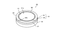
- FIG. 9 is a perspective view showing a state in which a supported body is mounted on the mounting table of the electrostatic chuck device according to one embodiment of the present disclosure.
- FIG. 10 is a perspective view showing a state in which a supported body is lifted from the mounting table of the electrostatic chuck device according to the embodiment of the present disclosure;
- the electrostatic chuck device 30 shown in FIGS. 9 and 10 has a holding portion 32 on which a mounting table 31 is mounted.
- the mounting table 31 has a mounting surface 31a on which the wafer W is mounted.
- the holding part 32 is disc-shaped and arranged on the side opposite to the mounting table 31 (below the electrostatic adsorption electrode).
- the holding unit 32 cools the mounting table 31 and adjusts it to a desired temperature.
- the holding part 32 has a channel for circulating water therein.
- the holding portion 32 is made of, for example, aluminum, aluminum alloy, copper, copper alloy, stainless steel (SUS), titanium, or the like.
- an insulating film such as aluminum oxide is formed on at least the surface of the holding part 32 exposed to the plasma.
- the focus ring 33 includes an upper ring 34 positioned above and a lower ring 35 positioned below the upper ring 34 .
- the upper ring 34 includes a fixed portion 37 provided along the circumference and a movable portion 36 provided concentrically with the fixed portion 37 and displaceable in the vertical direction.
- the movable part 36 is lifted to lift the wafer W.
- the lower surface of the movable portion 36 is provided with a positioning hole into which the height adjusting member 1 provided on the upper surface of the lower ring 35 is fitted.
- the movable portion 36 is positioned on the lower ring 35 when the movable portion 36 descends together with the lift pins 38 .
- the fixed part 37 is fixed to the lower ring 35 .
- the movable part 36 has openings 36b that are open at both ends, and is C-shaped in plan view.
- the fixed portion 37 is positioned inside the opening portion 36b in plan view.
- the movable portion 36 is in contact with the fixed portion 37 at both ends in the circumferential direction.
- the opening 36b of the movable portion 36 is open.
- a transfer mechanism such as a transfer arm for transferring the wafer W can be inserted into the opening 36b from the outside in the radial direction.
- the movable portion 36 has first surfaces 36a at both ends in the circumferential direction that are inclined downward.
- the fixed portion 37 has second surfaces 37a that are inclined upward at both ends in the circumferential direction.
- the first surface 36a and the second surface 37a overlap each other in the vertical direction due to their inclined surfaces.
- the opposing surfaces of the movable portion 36 and the fixed portion 37 extend obliquely. If the facing surface extends obliquely, the path through which the plasma penetrates becomes longer, so the penetration of the plasma into the gap between the movable portion 36 and the fixed portion 37 is suppressed.
- the inclination angle of the first surface 36a and the second surface 37a with respect to the horizontal direction is preferably 45° or less.
- the base portion 2 has a circular shape when viewed from above.
- the base 2 is not limited to a circular shape.
- the base 2 may have an elliptical shape in plan view, or may have a polygonal shape such as a triangular, quadrangular, pentagonal, or hexagonal shape, depending on the desired application.
- the support portion 3 is also not limited to a cylindrical shape.
- the support portion 3 may have an elliptical columnar shape, or may have a prismatic shape such as a triangular columnar shape, a square columnar shape, a pentagonal columnar shape, a hexagonal columnar shape, or a shape other than a columnar shape. may have
- the method of manufacturing the height adjustment member 1 described above describes a method of integrally molding the base portion 2 and the support portion 3 .
- the height adjustment member according to the present disclosure may be manufactured by molding the base 2 and the support 3 separately, firing them, and then joining the base 2 and the support 3 together.
- the bonding method is not limited, and examples thereof include diffusion bonding.
- the content and average particle size (D 50 ) of the pore-forming agent with respect to 100 parts by mass of ⁇ -type silicon carbide powder were as shown in Table 1. Furthermore, 0.2% by mass of sodium polycarboxylate as a pore dispersing agent was added to each sample with respect to 100% by mass of the pore forming agent to prepare raw materials. Each sample of this prepared raw material was put into a ball mill and then mixed for 48 hours to form a slurry. A binder was added to this slurry, mixed, and then spray-dried to obtain granules of silicon carbide having an average particle size of 80 ⁇ m.
- the granules were filled into a mold and pressed in the thickness direction with a pressure of 98 MPa to form a compact.
- the resulting compact was heated in a nitrogen atmosphere for 20 hours, held at 600° C. for 5 hours, and then naturally cooled and degreased to obtain a degreased compact.
- the degreased bodies were held in a vacuum atmosphere at 2030° C. for 5 hours to obtain disc-shaped and prism-shaped samples made of ceramics containing silicon carbide as a main component.
Landscapes
- Engineering & Computer Science (AREA)
- Chemical & Material Sciences (AREA)
- Physics & Mathematics (AREA)
- Manufacturing & Machinery (AREA)
- Computer Hardware Design (AREA)
- Power Engineering (AREA)
- Microelectronics & Electronic Packaging (AREA)
- General Physics & Mathematics (AREA)
- Condensed Matter Physics & Semiconductors (AREA)
- Plasma & Fusion (AREA)
- Chemical Kinetics & Catalysis (AREA)
- Organic Chemistry (AREA)
- General Chemical & Material Sciences (AREA)
- Materials Engineering (AREA)
- Metallurgy (AREA)
- Mechanical Engineering (AREA)
- Crystallography & Structural Chemistry (AREA)
- Container, Conveyance, Adherence, Positioning, Of Wafer (AREA)
Abstract
A height adjustment member according to the present disclosure comprises: a base part; and a support part that is positioned on the upper surface of the base part, while having a facing surface that faces a body to be supported. At least the support part contains a ceramic that is mainly composed of silicon carbide, silicon carbonitride or sialon. This height adjustment member has a plurality of closed pores; and the value (C) obtained by subtracting the average (B) of the circle-equivalent diameters of the closed pores from the average (A) of the distances between centroids of two closed pores adjacent to each other is 50 µm to 170 µm.
Description
本発明は、高さ調節部材、熱処理装置および静電チャック装置に関する。
The present invention relates to a height adjusting member, a heat treatment device and an electrostatic chuck device.
従来、半導体ウエハ、LCD基板などの被処理体を載置台で熱処理するための熱処理装置が使用されている。このような熱処理装置には、例えば、特許文献1に記載のように、半導体ウエハ、LCD基板などの被処理体を支持するための高さ調節部材(プランジャーおよびギャップピン)が備えられている。
Conventionally, a heat treatment apparatus has been used for heat-treating workpieces such as semiconductor wafers and LCD substrates on a mounting table. Such a heat treatment apparatus is provided with a height adjusting member (plunger and gap pin) for supporting an object to be processed such as a semiconductor wafer or an LCD substrate, as described in Patent Document 1, for example. .
本開示に係る高さ調節部材は、基部と、基部の上面に位置し、被支持体に対向する対向面を有する支持部とを含む。少なくとも支持部は、炭化珪素、炭窒化珪素またはサイアロンを主成分とするセラミックスを含む。閉気孔を複数有し、隣り合う閉気孔の重心間距離の平均値(A)から閉気孔の円相当径の平均値(B)を引いた値(C)が、50μm以上170μm以下である。
A height adjustment member according to the present disclosure includes a base and a support portion located on the upper surface of the base and having a facing surface facing a supported body. At least the supporting portion contains ceramics containing silicon carbide, silicon carbonitride or sialon as a main component. It has a plurality of closed pores, and the value (C) obtained by subtracting the average circle-equivalent diameter (B) of the closed pores from the average distance (A) between the centers of gravity of adjacent closed pores is 50 μm or more and 170 μm or less.
本開示に係る熱処理装置は、載置台と上記の高さ調節部材とを備える。被支持体が載置台上に隙間を設けて載置されるように、高さ調節部材が載置台に設けられている。
A heat treatment apparatus according to the present disclosure includes a mounting table and the height adjustment member. A height adjusting member is provided on the mounting table so that the supported body is mounted on the mounting table with a gap therebetween.
本開示に係る静電チャック装置は、載置台と、載置台の周囲に位置するフォーカスリングとを備える。フォーカスリングが、円周に沿って設けられた固定部と、固定部と同心円上に設けられ、上下方向に変位可能な可動部とを備える。固定部の上面に、上記の高さ調節部材が位置している。
An electrostatic chuck device according to the present disclosure includes a mounting table and a focus ring positioned around the mounting table. A focus ring includes a fixed portion provided along the circumference and a movable portion provided concentrically with the fixed portion and displaceable in the vertical direction. The height adjusting member is positioned on the upper surface of the fixed portion.
本開示の一実施形態に係る高さ調節部材を、図1~3に基づいて詳細に説明する。図1は、本開示の一実施形態に係る高さ調節部材1が支持プレート4に取り付けられた状態を示す断面図の一部である。図2は、本開示の一実施形態に係る高さ調節部材1を示す斜視図である。図2に示す高さ調節部材1は、基部2と支持部3とを含む。
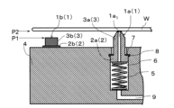
A height adjustment member according to one embodiment of the present disclosure will be described in detail based on FIGS. FIG. 1 is a partial cross-sectional view showing a height adjustment member 1 attached to a support plate 4 according to an embodiment of the present disclosure. FIG. 2 is a perspective view showing the height adjustment member 1 according to one embodiment of the present disclosure. The height adjustment member 1 shown in FIG. 2 includes a base portion 2 and a support portion 3 .
図1に示すように、高さ調節部材1は、処理空間内でSi基板、SiC基板、GaN基板などの被支持体Wを支持するための支持プレート4に取り付けられたプランジャー1aやギャップピン1bである。支持プレート4は、円板状であり、その内部に被支持体Wを加熱するヒータを備えている。プランジャー1aは、基部2aと、基部2aの上面に位置し、被支持体に対向する対向面を有する支持部3aとを含んでいる。ギャップピン1bは、基部2bと、基部2bの上面に位置し、被支持体Wに対向する対向面を有する支持部3bとを含んでいる。
As shown in FIG. 1, the height adjustment member 1 includes a plunger 1a and gap pins attached to a support plate 4 for supporting a supported body W such as a Si substrate, SiC substrate, or GaN substrate in the processing space. 1b. The support plate 4 is disc-shaped and has a heater for heating the body W to be supported therein. The plunger 1a includes a base portion 2a and a support portion 3a located on the upper surface of the base portion 2a and having a facing surface facing the supported body. The gap pin 1b includes a base portion 2b and a support portion 3b located on the upper surface of the base portion 2b and having a facing surface facing the body W to be supported.
プランジャー1aは、ギャップピン1bの頂面と同一高さ上にある第1位置P1と、第1位置P1よりも上方にある第2位置P2との間で、プランジャー1aの下側に設置されたスプリングなどの弾性部材5によって上下方向に移動することができる。プランジャー1aは、第1位置P1、第2位置P2いずれでも被支持体Wを支持することができる。ギャップピン1bは第1位置P1で被支持体Wを支持することによって、支持プレート4から一定の間隔が与えられ、ヒータによって被支持体Wの温度が上昇しても、その温度のばらつきを十分抑制することができる。ギャップピン1bは支持プレート4に、例えば、接合によって、円周方向に沿って所定間隔で複数固定されている。
The plunger 1a is placed below the plunger 1a between a first position P1 on the same height as the top surface of the gap pin 1b and a second position P2 above the first position P1. It can be vertically moved by an elastic member 5 such as a spring. The plunger 1a can support the supported body W at either the first position P1 or the second position P2. The gap pins 1b are provided with a constant distance from the support plate 4 by supporting the supported body W at the first position P1. can be suppressed. A plurality of gap pins 1b are fixed to the support plate 4 at predetermined intervals along the circumferential direction, for example, by bonding.
支持プレート4は、内部に円周状の溝6を有し、この溝6に複数のプランジャー1aが互いに所定間隔で設置されている。プランジャー1aが溝6から抜けないようにするために、基部2aを囲繞する環状の封止部材7を装着する段差部8が溝6の円周方向に沿って互いに所定間隔で設置されている。段差部8は、軸方向に垂直な断面が円状であって、溝6の幅よりも大きい直径を有している。
The support plate 4 has a circumferential groove 6 inside, and a plurality of plungers 1a are installed in the groove 6 at predetermined intervals. In order to prevent the plunger 1a from slipping out of the groove 6, stepped portions 8 for mounting an annular sealing member 7 surrounding the base portion 2a are provided along the circumferential direction of the groove 6 at predetermined intervals. . The stepped portion 8 has a circular cross section perpendicular to the axial direction and has a diameter larger than the width of the groove 6 .
プランジャー1aは、軸心に沿って貫通孔1a1を備え、溝6に連通している。貫通孔1a1および溝6の内部は、溝6に連結された流路9を介して真空ポンプなどの排気手段によって排気され、被支持体Wを吸着、固定することができる。
The plunger 1a has a through hole 1a1 along its axis and communicates with the groove 6. As shown in FIG. The interior of the through hole 1a1 and the groove 6 is evacuated by an exhaust means such as a vacuum pump through the channel 9 connected to the groove 6, so that the object W to be supported can be adsorbed and fixed.
以下、特に問題のない限り、基部2a、2bを基部2、支持部3a、3bを支持部3として説明する。基部2は平板状を有する部材であり、図2に示す基部2は、平面視した場合に円形状を有している。基部2は、後述する支持部3を固定するための部材であり、例えば、セラミックスで形成されている。セラミックスとしては限定されず、例えば、炭化珪素、炭窒化珪素、窒化珪素またはサイアロンを主成分とするセラミックスが挙げられる。
Hereinafter, the bases 2a and 2b will be referred to as the base 2, and the support portions 3a and 3b will be referred to as the support portion 3, unless there is a particular problem. The base 2 is a member having a flat plate shape, and the base 2 shown in FIG. 2 has a circular shape when viewed from above. The base portion 2 is a member for fixing the support portion 3, which will be described later, and is made of ceramics, for example. Ceramics are not limited, and examples thereof include ceramics containing silicon carbide, silicon carbonitride, silicon nitride, or sialon as a main component.
本明細書において「主成分」とは、セラミックスを構成している成分の合計100質量%のうち、80質量%以上を占める成分を意味する。セラミックスを構成している成分は、CuKα線を用いたX線回折装置(XRD)によって同定することができる。各成分の含有量は、例えばICP(Inductively Coupled Plasma)発光分光分析装置または蛍光X線分析装置により求めることができる。
As used herein, the term "main component" means a component that accounts for 80% by mass or more of the total 100% by mass of the components that make up the ceramics. The components that make up the ceramics can be identified by an X-ray diffractometer (XRD) using CuKα rays. The content of each component can be determined by, for example, an ICP (Inductively Coupled Plasma) emission spectrometer or a fluorescent X-ray spectrometer.
基部2の大きさは、例えば、高さ調節部材1を備える装置の大きさなどに応じて、適宜設定される。平面視で基部2aが円形状を有している場合、基部2aの直径は、例えば、3.5mm以上6.5mm以下である。基部2aの高さは、例えば、2mm以上4.4mm以下である。図2に示すように、平面視で基部2bが円形状を有している場合、基部2bの直径(図3のD1)は、例えば、3.5mm以上6.5mm以下である。基部2bの高さ(図3のH1)は、例えば、0.5mm以上1.1mm以下である。
The size of the base 2 is appropriately set according to, for example, the size of the device including the height adjustment member 1. When the base 2a has a circular shape in plan view, the diameter of the base 2a is, for example, 3.5 mm or more and 6.5 mm or less. The height of the base 2a is, for example, 2 mm or more and 4.4 mm or less. As shown in FIG. 2, when the base 2b has a circular shape in plan view, the diameter of the base 2b (D1 in FIG. 3) is, for example, 3.5 mm or more and 6.5 mm or less. The height of the base portion 2b (H1 in FIG. 3) is, for example, 0.5 mm or more and 1.1 mm or less.
支持部3は、例えば、筒状あるいは柱状を有する部材であり、図1に示す支持部3aは円筒状、支持部3bは円柱状を有している。支持部3は、被支持体Wを支持するための部材であり、炭化珪素、炭窒化珪素、窒化珪素またはサイアロンを主成分とするセラミックス(以下、これらの成分を主成分とするセラミックスを便宜的に非酸化物セラミックスという場合がある。)で形成されている。
The support part 3 is, for example, a member having a cylindrical shape or a columnar shape. The support part 3a shown in FIG. 1 has a cylindrical shape, and the support part 3b has a columnar shape. The supporting portion 3 is a member for supporting the object W to be supported, and is made of ceramics containing silicon carbide, silicon carbonitride, silicon nitride or sialon as a main component (hereinafter, ceramics containing these components as a main component is used for convenience). It is sometimes called non-oxide ceramics.).
少なくとも支持部3が、非酸化物セラミックスで形成されていると、高さ調節部材1が加熱および冷却を繰り返す環境で使用されても、伸縮が生じにくくなり変形しにくくなる。その理由としては、非酸化物セラミックスは、平均線膨張率が小さいためである。非酸化物セラミックスの40℃~400℃における平均線膨張率は、例えば、2~4×10⁻⁶/Kであり、この平均線膨張率は、例えば、JIS R 1618:2002に準拠して求めることができる。
When at least the support portion 3 is made of non-oxide ceramics, even if the height adjustment member 1 is used in an environment where heating and cooling are repeated, expansion and contraction are less likely to occur and deformation is less likely to occur. The reason for this is that non-oxide ceramics have a small average coefficient of linear expansion. The average coefficient of linear expansion of non-oxide ceramics at 40° C. to 400° C. is, for example, 2 to 4×10 −6 /K, and this average linear expansion coefficient is determined according to, for example, JIS R 1618:2002. be able to.
支持部3は、上述の基部2と主成分が同じセラミックスで形成されていてもよく、主成分が異なるセラミックスで形成されていてもよい。通常、支持部3と基部2とは、主成分が同じセラミックスで一体的に成形されている。
The support portion 3 may be formed of ceramics having the same main component as that of the base portion 2 described above, or may be formed of ceramics having a different main component. Normally, the support portion 3 and the base portion 2 are integrally formed of ceramics having the same main component.
支持部3の大きさは、例えば、高さ調節部材1を備える装置の大きさなどに応じて、適宜設定される。平面視で支持部3aが円形状を有している場合、支持部3aの直径は、例えば、2mm以上3mm以下である。支持部3aの高さは、例えば、4.8mm以上7.2mm以下である。
図2に示すように、円柱状を有する支持部3bの場合、支持部3bの直径(図3のD2)は、例えば、2mm以上3mm以下である。支持部3bの高さ(図3のH2)は、例えば、1.2mm以上1.8mm以下である。 The size of thesupport portion 3 is appropriately set according to, for example, the size of the device including the height adjustment member 1 . When the support portion 3a has a circular shape in plan view, the diameter of the support portion 3a is, for example, 2 mm or more and 3 mm or less. The height of the support portion 3a is, for example, 4.8 mm or more and 7.2 mm or less.
As shown in FIG. 2, in the case of the supportingportion 3b having a cylindrical shape, the diameter of the supporting portion 3b (D2 in FIG. 3) is, for example, 2 mm or more and 3 mm or less. The height (H2 in FIG. 3) of the support portion 3b is, for example, 1.2 mm or more and 1.8 mm or less.
図2に示すように、円柱状を有する支持部3bの場合、支持部3bの直径(図3のD2)は、例えば、2mm以上3mm以下である。支持部3bの高さ(図3のH2)は、例えば、1.2mm以上1.8mm以下である。 The size of the
As shown in FIG. 2, in the case of the supporting
一実施形態に係る高さ調節部材1は、図4に示すように、複数の閉気孔41を有する。図4は、一実施形態に係る高さ調節部材1の断面を研磨して得られた研磨面を示す顕微鏡写真である。図5A、5Bは、図4の領域Xを拡大した顕微鏡写真であり、隣り合う閉気孔の重心間距離x1,x2,x3および、隣り合う閉気孔の円相当径d1,d2,d3をそれぞれ示している。高さ調節部材1において、隣り合う閉気孔41a,41b,41c,・・・の重心間距離x1,x2,x3,・・・の平均値(A)から、閉気孔41a,41b,41c,・・・の円相当径d1,d2,d3,・・・の平均値(B)を引いた値(C)は、50μm以上170μm以下である。
The height adjusting member 1 according to one embodiment has a plurality of closed pores 41, as shown in FIG. FIG. 4 is a micrograph showing a polished surface obtained by polishing a cross section of the height adjusting member 1 according to one embodiment. 5A and 5B are enlarged micrographs of region X in FIG. 4, showing the distances x1, x2, and x3 between the centers of gravity of adjacent closed pores and the equivalent circle diameters d1, d2, and d3 of adjacent closed pores, respectively. ing. In the height adjusting member 1, the closed pores 41a, 41b, 41c, . The value (C) obtained by subtracting the average value (B) of the equivalent circle diameters d1, d2, d3, . . . of .
この値(C)が50μm以上であれば、閉気孔率が減少して剛性が向上する。その結果、得られる高さ調節部材1がたわみにくくなる。一方、この値(C)が170μm以下であれば、熱伝導が隣り合う閉気孔41によって妨げられる傾向が強くなる。さらに、マイクロクラックが生じても、閉気孔41によってマイクロクラックが進展しにくくなる。これらのことから、得られる高さ調節部材1の耐熱衝撃性が向上する。
If this value (C) is 50 μm or more, the closed porosity is reduced and the rigidity is improved. As a result, the resulting height adjustment member 1 is less likely to bend. On the other hand, if this value (C) is 170 μm or less, there is a strong tendency for heat conduction to be hindered by adjacent closed pores 41 . Furthermore, even if a microcrack occurs, the closed pores 41 make it difficult for the microcrack to propagate. For these reasons, the obtained height adjustment member 1 has improved thermal shock resistance.
閉気孔41の重心間距離は、例えば、以下の方法で求めることができる。高さ調節部材1の断面を研磨して得られる研磨面を50倍の倍率で観察し、平均的な範囲を選択して、例えば、面積が1.768mm2(横方向の長さが1.36mm、縦方向の長さが1.3mm)となる範囲をCCDカメラで撮影して、観察像を得る。ここで、研磨面の算術平均粗さRaは、例えば、0.2μm以下とし、この算術平均粗さRaはJIS B 0601:2013に準拠して求めればよい。この観察像を対象として、例えば、画像解析ソフト「A像くん(ver2.52)」(登録商標、旭化成エンジニアリング(株)製)を用いて、分散度計測の重心間距離法という手法で閉気孔41の重心間距離を求めればよい。以下、画像解析ソフト「A像くん」と記載した場合、旭化成エンジニアリング(株)製の画像解析ソフトを示す。
The distance between the centers of gravity of the closed pores 41 can be obtained, for example, by the following method. A polished surface obtained by polishing a cross section of the height adjustment member 1 is observed at a magnification of 50 times, and an average range is selected, for example, with an area of 1.768 mm 2 (horizontal length of 1.768 mm 2 ). An observation image is obtained by photographing a range of 36 mm and a length of 1.3 mm in the vertical direction with a CCD camera. Here, the arithmetic mean roughness Ra of the polished surface is, for example, 0.2 μm or less, and this arithmetic mean roughness Ra may be obtained in accordance with JIS B 0601:2013. Using this observation image as an object, for example, using the image analysis software "Azou-kun (ver 2.52)" (registered trademark, manufactured by Asahi Kasei Engineering Co., Ltd.), the closed pores are measured by the method of the distance between the centers of gravity of the dispersion measurement. The distance between the centers of gravity of 41 can be obtained. Hereinafter, when the image analysis software is described as "Azo-kun", it indicates the image analysis software manufactured by Asahi Kasei Engineering Corporation.
この手法の設定条件としては、例えば、画像の明暗を示す指標であるしきい値を156、明度を暗、小図形除去面積を20μm2、雑音除去フィルタを無とすればよい。観察像の明るさに応じて、しきい値は調整すればよく、明度を暗、2値化の方法を手動とし、小図形除去面積を20μm2および雑音除去フィルタを無とした上で、観察像に現れるマーカーが閉気孔41の形状と一致するように、しきい値を調整すればよい。
The setting conditions for this method are, for example, a threshold of 156, which is an index indicating the brightness of an image, a dark brightness, a small figure removal area of 20 μm 2 , and no noise removal filter. The threshold value can be adjusted according to the brightness of the observation image. The threshold may be adjusted so that the marker appearing in the image matches the shape of the closed pore 41 .
閉気孔41の円相当径は、上記観察像を対象として、粒子解析という手法で求めればよい。この手法の設定条件も分散度計測の重心間距離法で用いた設定条件と同じにすればよい。
The circle-equivalent diameter of the closed pores 41 can be obtained by a method called particle analysis, using the observation image as a target. The setting conditions for this method may be the same as the setting conditions used in the centroid distance method for measuring the degree of dispersion.
閉気孔41の重心間距離の尖度Kuは0.3以上4以下であってもよい。閉気孔41の重心間距離の尖度Kuが0.3以上である場合、閉気孔41の重心間距離のバラツキが小さくなる(すなわち、閉気孔41の重心間距離の分布が狭くなる)。その結果、局部的に機械的特性に乏しい部分が少なくなる。一方、閉気孔41の重心間距離の尖度Kuが4以下である場合、互いに極端に離れた閉気孔41が存在しなくなる。その結果、耐熱衝撃性をより向上させることができる。
The kurtosis Ku of the distance between the centers of gravity of the closed pores 41 may be 0.3 or more and 4 or less. When the kurtosis Ku of the distances between the centers of gravity of the closed pores 41 is 0.3 or more, the variation in the distances between the centers of gravity of the closed pores 41 is reduced (that is, the distribution of the distances between the centers of gravity of the closed pores 41 is narrowed). As a result, there are fewer parts that are locally poor in mechanical properties. On the other hand, when the kurtosis Ku of the distance between the centers of gravity of the closed pores 41 is 4 or less, the closed pores 41 extremely separated from each other do not exist. As a result, thermal shock resistance can be further improved.
ここで、尖度Kuとは、分布のピークと裾が正規分布からどれだけ異なっているかを示す指標(統計量)である。尖度Ku>0である場合、鋭いピークと長く太い裾を有する分布となる。尖度Ku=0である場合、正規分布となる。尖度Ku<0である場合、分布は丸みがかったピークと短く細い尾を有する分布となる。重心間距離の尖度Kuは、Excel(登録商標、Microsoft Corporation)に備えられている関数Kurtを用いて求めればよい。
Here, the kurtosis Ku is an index (statistic) that indicates how much the peak and tail of the distribution differ from the normal distribution. When the kurtosis Ku>0, the distribution has a sharp peak and a long and thick tail. If the kurtosis is Ku=0, the distribution is normal. If the kurtosis Ku<0, the distribution will have a rounded peak and a short thin tail. The kurtosis Ku of the distance between the centroids can be obtained using the function Kurt provided in Excel (registered trademark, Microsoft Corporation).
非酸化物セラミックスは、図6に示すように、粗粒状結晶粒子42を有していてもよい。本明細書において「粗粒状結晶粒子」とは、面積が1000μm2以上の結晶粒子を意味する。この粗粒状結晶粒子42の割合は限定されず、例えば、粗粒状結晶粒子42の面積は6面積%以上15面積%以下であってもよい。粗粒状結晶粒子42の面積が6面積%以上の場合、熱衝撃によって微細なクラックが生じても、粗粒状結晶粒子42によってクラックを進展しにくくすることができる。一方、粗粒状結晶粒子42の面積が15面積%以下の場合、機械的特性(強度、剛性、破壊靭性など)を向上させることができる。
Non-oxide ceramics may have coarse grains 42 as shown in FIG. As used herein, the term "coarse crystal grains" means crystal grains having an area of 1000 μm 2 or more. The proportion of the coarse crystal grains 42 is not limited, and for example, the area of the coarse grain crystal grains 42 may be 6 area % or more and 15 area % or less. When the area of the coarse crystal grains 42 is 6 area % or more, even if fine cracks occur due to thermal shock, the coarse grain crystal grains 42 can prevent the cracks from propagating. On the other hand, when the area of the coarse grain crystal grains 42 is 15 area % or less, the mechanical properties (strength, rigidity, fracture toughness, etc.) can be improved.
粗粒状結晶粒子42は粒内気孔44を含んでいてもよい。粗粒状結晶粒子42が粒内気孔44を含んでいると、高温環境下で粗粒状結晶粒子42に生じる熱応力が粒内気孔44によって緩和されやすくなる。その結果、耐熱性が向上する。粒内気孔44の円相当径は、例えば6μm以下である。
The coarse-grained crystal grains 42 may contain intragranular pores 44 . When the coarse grain crystal grains 42 contain intragranular pores 44 , the thermal stress generated in the coarse grain crystal grains 42 in a high-temperature environment is easily relieved by the intragranular pores 44 . As a result, heat resistance is improved. The equivalent circle diameter of the intragranular pores 44 is, for example, 6 μm or less.
粗粒状結晶粒子42の面積を求める場合、様々な大きさの結晶粒子が平均的に観察される面を選択する。例えば、セラミックスを、水酸化ナトリウムおよび硝酸カリウムが1:1の質量比からなる加熱溶融された溶液に20秒浸漬することによって、セラミックスの研磨面をエッチングする。このエッチングされた面を50倍の倍率で光学顕微鏡を用いて広く観察し、粗粒状結晶粒子42や微粒状結晶粒子43が平均的に存在する面を選択する。その面の面積は、例えば、2.7×10⁻²μm2(横方向の長さが0.19μm、縦方向の長さが0.14μm)とすればよい。
図6で示す微粒状結晶粒子43の円相当径の平均値(D)は、例えば、8μm以下である。結晶粒径が8μmを超えて面積が170μm2未満の結晶粒子が存在していてもよい。 When determining the area of thecoarse crystal grains 42, select a surface where crystal grains of various sizes are observed on average. For example, the polished surface of the ceramic is etched by immersing the ceramic for 20 seconds in a heated and melted solution containing sodium hydroxide and potassium nitrate at a mass ratio of 1:1. This etched surface is broadly observed using an optical microscope at a magnification of 50 times, and a surface on which coarse crystal grains 42 and fine crystal grains 43 are evenly present is selected. The surface area may be, for example, 2.7×10 −2 μm 2 (horizontal length is 0.19 μm, vertical length is 0.14 μm).
The average value (D) of the circle-equivalent diameters of thefine crystal grains 43 shown in FIG. 6 is, for example, 8 μm or less. Crystal grains having a grain size greater than 8 μm and an area less than 170 μm 2 may be present.
図6で示す微粒状結晶粒子43の円相当径の平均値(D)は、例えば、8μm以下である。結晶粒径が8μmを超えて面積が170μm2未満の結晶粒子が存在していてもよい。 When determining the area of the
The average value (D) of the circle-equivalent diameters of the
支持部3の対向面3cは、微粒状結晶粒子および開気孔を有する。対向面3cにおける微粒状結晶粒子の円相当径の平均値(D)は、開気孔の円相当径の平均値(E)よりも小さくてもよい。微粒状結晶粒子の円相当径の平均値(D)は、開気孔の円相当径の平均値(E)よりも小さい場合、開気孔の輪郭から脱粒しにくくなる。その結果、被支持体Wの被支持面に損傷を与えにくくなる。
The facing surface 3c of the support portion 3 has fine crystal grains and open pores. The average value (D) of the equivalent circle diameters of the fine crystal grains on the facing surface 3c may be smaller than the average value (E) of the equivalent circle diameters of the open pores. When the average equivalent circle diameter (D) of the fine crystal grains is smaller than the average equivalent circle diameter (E) of the open pores, the particles are less likely to shed from the outline of the open pores. As a result, the supported surface of the supported body W is less likely to be damaged.
微粒状結晶粒子の円相当径の平均値(D)は、開気孔の円相当径の平均値(E)よりも小さければ、限定されない。微粒状結晶粒子の円相当径の平均値(D)と開気孔の円相当径の平均値(E)との差は、例えば5μm以上であってもよく、上限は29μmであってもよい。本明細書において「微粒状結晶粒子」とは、円相当径が8μm以下の結晶粒子を意味する。
The average value (D) of the equivalent circle diameters of the fine crystal grains is not limited as long as it is smaller than the average value (E) of the equivalent circle diameters of the open pores. The difference between the average equivalent circle diameter (D) of the fine crystal grains and the average equivalent circle diameter (E) of the open pores may be, for example, 5 μm or more, and the upper limit may be 29 μm. As used herein, the term "fine grains" means grains having an equivalent circle diameter of 8 μm or less.
微粒状結晶粒子の円相当径の平均値(D)は、例えば、1μm以上6μm以下である。開気孔の円相当径の平均値(E)は、例えば、8μm以上30μm以下である。微粒状結晶粒子の円相当径は、例えば、上述した方法で、面積が2.7×10⁻²μm2のエッチングされた面を対象として、画像解析ソフト(例えば、三谷商事(株)製、Win ROOF)を用いて解析することによって得ることができる。解析にするに当たり、円相当径の閾値は、0.21μmとし、0.21μm未満の粒径は円相当径の平均値(D)算出の対象とはしない。
The average equivalent circle diameter (D) of the fine crystal grains is, for example, 1 μm or more and 6 μm or less. The average value (E) of equivalent circle diameters of open pores is, for example, 8 μm or more and 30 μm or less. The circle-equivalent diameter of the fine grain crystal grains can be determined, for example, by the method described above, with an etched surface having an area of 2.7×10 −2 μm 2 as a target, and image analysis software (for example, Mitani Shoji Co., Ltd., It can be obtained by analysis using Win ROOF). In the analysis, the threshold value of the equivalent circle diameter is set to 0.21 μm, and particle diameters smaller than 0.21 μm are not included in the calculation of the average value (D) of the equivalent circle diameter.
一実施形態に係る高さ調節部材1において、ダイヤモンドライクカーボン(DLC)膜が少なくとも支持部3の対向面3cに位置していてもよい。DLCとは、ダイヤモンドと黒鉛との中間に位置する素材である。DLC膜は、アルゴン、ヘリウムおよび水素の少なくともいずれかを、さらに含んでいてもよい。特に、水素を含んでいると、耐熱性および耐食性が向上したDLC膜とすることができる。DLC膜は、ラマン分光分析装置を用いて同定すればよい。
In the height adjusting member 1 according to one embodiment, a diamond-like carbon (DLC) film may be positioned at least on the facing surface 3c of the supporting portion 3. DLC is a material positioned between diamond and graphite. The DLC film may further contain at least one of argon, helium and hydrogen. In particular, when hydrogen is included, a DLC film having improved heat resistance and corrosion resistance can be obtained. A DLC film may be identified using a Raman spectrometer.
高さ調節部材1がプラズマ処理空間で使用される場合、プラズマ処理空間が支持部3の対向面3c側に位置すると、対向面3cの熱伝導率が高くなれば、支持部3の周囲に設置された部材は、対向面3cの輻射熱により、膨張しやすくなる。プラズマ処理によって、プラズマ処理空間で200℃~400℃程度の熱が生じることがある。DLC膜の熱伝導率は低い(例えば、20℃における熱伝導率は1W/(m・K)以下)ため、プラズマ処理空間で熱が生じても、DLC膜が対向面3cに位置していると、対向面3cの輻射熱が小さくなるので、支持部3の周囲に設置された部材を膨張させにくくすることができる。
When the height adjusting member 1 is used in the plasma processing space, if the plasma processing space is located on the side of the opposing surface 3c of the supporting part 3, if the thermal conductivity of the opposing surface 3c is high, it is installed around the supporting part 3. The member thus formed tends to expand due to the radiant heat of the facing surface 3c. Plasma processing may generate heat on the order of 200° C. to 400° C. in the plasma processing space. Since the DLC film has a low thermal conductivity (for example, the thermal conductivity at 20° C. is 1 W/(m·K) or less), the DLC film is positioned on the facing surface 3c even if heat is generated in the plasma processing space. As a result, the radiant heat of the facing surface 3c is reduced, so that the member installed around the support portion 3 can be made less likely to expand.
図2に示すように、支持部3が柱状体を有する場合、支持部3の側面3dにもDLC膜が位置していてもよい。支持部3の側面3dにもDLC膜が位置していると、上述した効果と同じ効果を得ることができる。
As shown in FIG. 2, when the support portion 3 has a columnar body, the DLC film may also be positioned on the side surface 3d of the support portion 3. If the DLC film is also positioned on the side surface 3d of the supporting portion 3, the same effects as those described above can be obtained.
さらに、支持部3の対向面3cに位置するDLC膜は、支持部3の側面3dに位置するDLC膜よりも厚くてもよい。このような構成であると、対向面3cによる遮熱効果は高くなる。ここで、支持部3が円柱状である場合、支持部3の側面3dは曲面となる。支持部3が角柱状である場合、支持部3の側面3d同士が交わる交線を有する。いずれの場合も、支持部3の側面3dのDLC膜は対向面3cのDLC膜よりも、内部応力が蓄積しやすくなる。支持部3の側面3dのDLC膜が対向面3cのDLC膜の厚みよりも小さければ、内部応力の蓄積の増加が抑制されるので、長期間に亘って用いることができる。
Furthermore, the DLC film located on the facing surface 3c of the support portion 3 may be thicker than the DLC film located on the side surface 3d of the support portion 3. With such a configuration, the heat shielding effect of the facing surface 3c is enhanced. Here, when the support portion 3 has a columnar shape, the side surface 3d of the support portion 3 is a curved surface. When the supporting portion 3 is prismatic, it has an intersection line where the side surfaces 3d of the supporting portion 3 intersect. In either case, the DLC film on the side surface 3d of the supporting portion 3 is more likely to accumulate internal stress than the DLC film on the opposing surface 3c. If the DLC film on the side surface 3d of the supporting portion 3 is thinner than the DLC film on the opposing surface 3c, the increase in the accumulation of internal stress is suppressed, so that it can be used for a long period of time.
対向面3cのDLC膜の厚みは、例えば、0.5μm以上3μm以下である。対向面3cのDLC膜の厚みと、側面3dのDLC膜の厚みとの差は、例えば、0.01μm以上0.8μm以下であってもよい。
The thickness of the DLC film on the facing surface 3c is, for example, 0.5 μm or more and 3 μm or less. The difference between the thickness of the DLC film on the facing surface 3c and the thickness of the DLC film on the side surface 3d may be, for example, 0.01 μm or more and 0.8 μm or less.
DLC膜は開気孔を複数有していてもよい。DLC膜が開気孔を有する場合、隣り合う開気孔の重心間距離の平均値(F)から開気孔の円相当径の平均値(G)を引いた値(H)が、前記値(C)よりも大きくてもよい。値(H)が値(C)よりも大きい場合、DLC膜の開気孔は疎らに点在していることになる。その結果、開気孔の内部から発生するパーティクルを低減することができる。
The DLC film may have multiple open pores. When the DLC film has open pores, the value (H) obtained by subtracting the average circle-equivalent diameter (G) of the open pores from the average distance between the centers of gravity of adjacent open pores (F) is the value (C). may be greater than If the value (H) is greater than the value (C), the open pores of the DLC film are sparsely scattered. As a result, particles generated from inside the open pores can be reduced.
図2に示すように、基部2が環状の鍔部を有していてもよい。このような構成の場合、鍔部(基部)2の環状面2cにDLC膜が位置していてもよい。鍔部2の環状面2cにDLC膜が位置していると、環状面2cの輻射熱が小さくなる。その結果、鍔部(基部)2の周囲に設置された部材の膨張を低減することができる。
As shown in FIG. 2, the base 2 may have an annular flange. In such a configuration, the DLC film may be positioned on the annular surface 2 c of the flange (base) 2 . When the DLC film is positioned on the annular surface 2c of the collar portion 2, radiant heat from the annular surface 2c is reduced. As a result, the expansion of the members installed around the flange (base) 2 can be reduced.
鍔部2は側面2dにもDLC膜が位置していてもよい。鍔部2の側面2dにもDLC膜が位置していると、上述した効果と同じ効果を得ることができる。
The DLC film may also be positioned on the side surface 2d of the collar portion 2. If the DLC film is also positioned on the side surface 2d of the collar portion 2, the same effects as those described above can be obtained.
さらに、鍔部2の環状面2cに位置するDLC膜が、鍔部2の側面2dに位置するDLC膜よりも厚くてもよい。このような構成であると、環状面2cによる遮熱効果は高くなる。ここで、鍔部2が円板状である場合、鍔部2の側面2dは曲面となる。鍔部2が角板状である場合、鍔部2の側面2d同士が交わる交線を有する。いずれの場合も、鍔部2の側面2dのDLC膜は環状面2cのDLC膜よりも、内部応力が蓄積しやすくなる。鍔部2の側面2dのDLC膜が環状面2cのDLC膜の厚みよりも小さければ、内部応力の蓄積の増加が抑制されるので、長期間に亘って用いることができる。
Furthermore, the DLC film located on the annular surface 2c of the collar portion 2 may be thicker than the DLC film located on the side surface 2d of the collar portion 2. Such a configuration enhances the heat shielding effect of the annular surface 2c. Here, when the collar portion 2 is disc-shaped, the side surface 2d of the collar portion 2 is a curved surface. When the collar portion 2 is square plate-shaped, it has an intersection line where the side surfaces 2d of the collar portion 2 intersect. In either case, the DLC film on the side surface 2d of the flange 2 is more likely to accumulate internal stress than the DLC film on the annular surface 2c. If the thickness of the DLC film on the side surface 2d of the flange 2 is smaller than the thickness of the DLC film on the annular surface 2c, an increase in the accumulation of internal stress can be suppressed, so that it can be used for a long period of time.
環状面2cのDLC膜の厚みは、例えば、0.5μm以上3μm以下である。環状面2cのDLC膜の厚みと、側面2dのDLC膜の厚みとの差は、例えば、0.01μm以上0.8μm以下であってもよい。
The thickness of the DLC film on the annular surface 2c is, for example, 0.5 μm or more and 3 μm or less. The difference between the thickness of the DLC film on the annular surface 2c and the thickness of the DLC film on the side surface 2d may be, for example, 0.01 μm or more and 0.8 μm or less.
一実施形態に係る高さ調節部材1を製造する方法は限定されず、例えば次のような手順で製造される。高さ調節部材1を形成しているセラミックスの主成分が炭化珪素である場合、例えば、平均粒径(D50)が0.5μm以上2μm以下であるα型炭化珪素の粉末、焼結助剤、樹脂ビーズからなる疎水性の気孔形成剤およびこの気孔形成剤を分散させる気孔分散剤を準備する。次いで、これらの原料を、バレルミル、回転ミル、振動ミル、ビーズミルまたはアトライターなどで湿式混合、粉砕してスラリーとする。炭化珪素の粉末を分散させる分散剤を添加してもよい。
The method of manufacturing the height adjustment member 1 according to one embodiment is not limited, and the height adjustment member 1 is manufactured, for example, by the following procedure. When the main component of the ceramics forming the height adjustment member 1 is silicon carbide, for example, an α-type silicon carbide powder having an average particle size (D 50 ) of 0.5 μm or more and 2 μm or less, and a sintering aid A hydrophobic pore-forming agent consisting of resin beads and a pore-dispersing agent for dispersing the pore-forming agent are prepared. These raw materials are then wet-mixed and pulverized by a barrel mill, rotary mill, vibration mill, bead mill, attritor, or the like to form a slurry. A dispersant that disperses the silicon carbide powder may be added.
焼結助剤は炭化硼素の粉末とカーボン源としてフェノール水溶液あるいはリグニンスルホン酸塩およびリグニンカルボン酸塩の粉末を組み合わせるか、あるいは酸化アルミニウムの粉末と酸化イットリウムなどの希土類酸化物の粉末とを組み合わせてもよい。焼結助剤が前者の組み合わせからなる場合には、α型炭化珪素の粉末100質量部に対して、例えば、炭化硼素の粉末は0.2質量部以上0.6質量部以下であり、フェノール水溶液あるいはリグニンスルホン酸塩およびリグニンカルボン酸塩の粉末は、炭素換算で0.5質量部4.0質量部である。リグニンスルホン酸塩およびリグニンカルボン酸塩の塩は、リチウム、ナトリウムおよびアンモニウムの少なくとも1種であるとよい。
The sintering aid is a combination of boron carbide powder and a phenol aqueous solution or lignin sulfonate and lignin carboxylate powder as a carbon source, or a combination of aluminum oxide powder and rare earth oxide powder such as yttrium oxide. good too. When the sintering aid consists of the former combination, for example, 0.2 parts by mass or more and 0.6 parts by mass or less of the boron carbide powder is used with respect to 100 parts by mass of the α-type silicon carbide powder, and phenol The aqueous solution or powder of lignin sulfonate and lignin carboxylate is 0.5 parts by mass and 4.0 parts by mass in terms of carbon. The salt of lignin sulfonate and lignin carboxylate is preferably at least one of lithium, sodium and ammonium.
気孔形成剤は、例えば、シリコーンビーズ、およびポリアクリルもしくはポリスチレンの少なくとも1種からなる懸濁重合された架橋性の樹脂ビーズである。支持部が閉気孔を複数有し、上記値(C)が、50μm以上170μm以下である高さ調整部材を得るには、気孔形成剤の含有量を、α型炭化珪素の粉末100質量部に対して、1.2質量部以上1.76質量部以下とし、その平均粒径(D50)を36μm以上45μm以下、特に40μm以上45μm以下とすればよい。特に、気孔形成剤の含有量は、α型炭化珪素の粉末100質量部に対して、1.2質量部以上1.38質量部以下であるとよい。
Pore-forming agents are, for example, silicone beads and suspension-polymerized crosslinkable resin beads composed of at least one of polyacrylic or polystyrene. In order to obtain a height adjusting member in which the supporting portion has a plurality of closed pores and the above value (C) is 50 μm or more and 170 μm or less, the content of the pore forming agent is added to 100 parts by mass of α-silicon carbide powder. On the other hand, it should be 1.2 parts by mass or more and 1.76 parts by mass or less, and the average particle size (D 50 ) should be 36 μm or more and 45 μm or less, particularly 40 μm or more and 45 μm or less. In particular, the content of the pore-forming agent is preferably 1.2 parts by mass or more and 1.38 parts by mass or less with respect to 100 parts by mass of the α-silicon carbide powder.
気孔形成剤の粒径の範囲は、例えば、5μm以上125μm以下である。例えば、開気孔の重心間距離の尖度Kuが0.3以上4以下である高さ調整部材を得るには、平均粒径(D50)が42.5μm以上44.5μm以下である気孔形成剤を用いればよい。
The particle size range of the pore-forming agent is, for example, 5 μm or more and 125 μm or less. For example, in order to obtain a height adjusting member having an open pore center-to-center distance kurtosis Ku of 0.3 or more and 4 or less, the average particle diameter (D 50 ) is 42.5 μm or more and 44.5 μm or less. agent should be used.
気孔分散剤は、気孔形成剤を分散させるために使用される。気孔分散剤としては、例えば、カルボン酸塩、スルホン酸塩、硫酸エステル塩、リン酸エステル塩などのアニオン界面活性剤などが挙げられる。アニオン界面活性剤が気孔形成剤に吸着することによって、気孔形成剤はスラリー中に容易に湿潤および浸透する。さらに、アニオン界面活性剤が有する親水基の電荷反発により、気孔形成剤の凝集がさらに抑制される。そのため、気孔形成剤がスラリー中に凝集することなく十分に分散することができる。アニオン界面活性剤は、気孔形成剤をスラリーに湿潤および浸透させる効果が高い。気孔分散剤は、気孔形成剤100質量部に対し、0.14質量部以上0.24質量部以下添加すればよい。
A pore dispersing agent is used to disperse the pore forming agent. Examples of pore dispersing agents include anionic surfactants such as carboxylates, sulfonates, sulfates, and phosphates. Adsorption of the anionic surfactant to the pore-forming agent facilitates wetting and penetration of the pore-forming agent into the slurry. Furthermore, aggregation of the pore-forming agent is further suppressed by charge repulsion of the hydrophilic group of the anionic surfactant. Therefore, the pore-forming agent can be sufficiently dispersed in the slurry without agglomeration. Anionic surfactants are highly effective in wetting and penetrating the pore former into the slurry. The pore dispersing agent may be added in an amount of 0.14 parts by mass or more and 0.24 parts by mass or less per 100 parts by mass of the pore forming agent.
次に、このスラリーに、バインダーとして、メチルセルロース、カルボキシメチルセルロースなどのセルロース類やその変成品、糖類、澱粉類、デキストリンやこれらの各種変成品、ポリビニルアルコールなどの水溶性各種合成樹脂や酢酸ビニルなどの合成樹脂エマルジョン、アラビアゴム、カゼイン、アルギン酸塩、グルコマンナン、グリセリン、ソルビタン脂肪酸エステルなどを添加し混合した後、噴霧乾燥することで顆粒を得る。得られた大部分の顆粒には、気孔形成剤が内包された状態となる。
Next, to this slurry, binders such as celluloses such as methyl cellulose and carboxymethyl cellulose and modified products thereof, sugars, starches, dextrin and various modified products thereof, various water-soluble synthetic resins such as polyvinyl alcohol and vinyl acetate are added. A synthetic resin emulsion, gum arabic, casein, alginate, glucomannan, glycerin, sorbitan fatty acid ester, etc. are added and mixed, and then spray-dried to obtain granules. Most of the obtained granules are in a state in which the pore-forming agent is encapsulated.
噴霧乾燥の前にASTM E 11-61に記載されている粒度番号が2000のメッシュまたはこのメッシュより細かいメッシュの篩いに通すことによって、粗大な不純物やゴミを除去する。さらに磁力を用いた除鉄機で除鉄するなどの方法で、鉄およびその化合物を除去するとよい。
Remove coarse impurities and debris by passing through a sieve with a particle size number of 2000 or a finer mesh as described in ASTM E 11-61 prior to spray drying. Furthermore, it is preferable to remove iron and its compounds by a method such as iron removal with an iron remover using magnetic force.
顆粒を成形型に充填し、1軸プレス成形装置あるいは冷間静水圧プレス成形装置を用いて、成形圧を78MPa以上128MPa以下として顆粒を加圧して、生密度が、例えば、1.8g/cm3以上1.95g/cm3以下である高さ調節部材1の元となる成形体を得る。高さ調節部材1がプランジャー1aの場合、切削加工により、貫通孔の下穴を形成してもよい。この成形体を窒素雰囲気中、温度450~650℃、保持時間2~10時間で脱脂して、脱脂体とする。脱脂体を真空雰囲気またはアルゴンガスなどの不活性ガスの減圧雰囲気中、温度を1800℃以上2200℃以下として、3時間以上5時間以下で保持することによって主成分が炭化珪素であるセラミックスからなる高さ調節部材1が得られる。
The granules are filled in a mold, and the granules are pressed at a molding pressure of 78 MPa or more and 128 MPa or less using a uniaxial press molding device or a cold isostatic press molding device, and the raw density is, for example, 1.8 g / cm. A molded body that is the base of the height adjusting member 1 having a weight of 3 or more and 1.95 g/cm 3 or less is obtained. When the height adjusting member 1 is a plunger 1a, a pilot hole for the through hole may be formed by cutting. This molded body is degreased in a nitrogen atmosphere at a temperature of 450 to 650° C. for a holding time of 2 to 10 hours to obtain a degreased body. The degreased body is maintained in a vacuum atmosphere or a reduced pressure atmosphere of an inert gas such as argon gas at a temperature of 1800° C. or more and 2200° C. or less for 3 hours or more and 5 hours or less, thereby forming a high-temperature A length adjusting member 1 is obtained.
この高さ調節部材1を高圧の窒素雰囲気中で1800℃以上2100℃以下の温度で熱処理すれば、主成分が炭窒化珪素のセラミックスからなる高さ調節部材1を得ることができる。ここで、窒素の圧力は、例えば、150MPa以上200MPa以下である。
By heat-treating this height adjusting member 1 at a temperature of 1800° C. or more and 2100° C. or less in a high-pressure nitrogen atmosphere, the height adjusting member 1 made of ceramics whose main component is silicon carbonitride can be obtained. Here, the pressure of nitrogen is, for example, 150 MPa or more and 200 MPa or less.
熱処理前の高さ調節部材1の質量に対し、熱処理後の高さ調節部材1の質量は、6質量%以上10質量%以下増加するように熱処理するとよい。窒化珪素の生成が増えて、熱伝導率が低下するためである。高さ調節部材1を形成しているセラミックスの主成分が窒化珪素である場合、まず、β化率が40%以下である窒化珪素の粉末、焼結助剤として酸化カルシウム、酸化アルミニウムおよび希土類元素の酸化物の各粉末、樹脂ビーズからなる疎水性の気孔形成剤ならびにこの気孔形成剤を分散させる気孔分散剤を、バレルミル、回転ミル、振動ミル、ビーズミルまたはアトライターなどを用いて湿式混合および粉砕してスラリーとする。
The heat treatment should be performed so that the mass of the height adjustment member 1 after heat treatment increases by 6 mass % or more and 10 mass % or less with respect to the mass of the height adjustment member 1 before heat treatment. This is because the production of silicon nitride increases and the thermal conductivity decreases. In the case where the main component of the ceramics forming the height adjusting member 1 is silicon nitride, first, silicon nitride powder having a beta-conversion rate of 40% or less, calcium oxide, aluminum oxide and rare earth elements as sintering aids. , a hydrophobic pore-forming agent consisting of resin beads, and a pore-dispersing agent for dispersing the pore-forming agent are wet-mixed and pulverized using a barrel mill, rotary mill, vibration mill, bead mill or attritor, etc. to make a slurry.
サイアロンを主成分とするセラミックスを得るには、上記窒化珪素の粉末を、β化率が40%以下であって、組成式がSi6-ZAlZOZN8-Z(z=0.1~1)で表され、固溶量zが0.05以上0.5以下であるサイアロンの粉末を用いればよい。
In order to obtain ceramics containing sialon as a main component, the above silicon nitride powder having a β-conversion rate of 40% or less and a composition formula of Si 6-Z Al ZO Z N 8-Z (z=0. 1 to 1), and a sialon powder having a solid solution amount z of 0.05 or more and 0.5 or less may be used.
ここで、酸化カルシウム,酸化アルミニウムおよび希土類元素の酸化物の各粉末の合計は、窒化珪素の粉末とこれら焼結助剤の粉末の合計との総和を100質量%とした場合、3質量%以上19.2質量%以下になるようにすればよい。焼結助剤の合計100質量%における、酸化カルシウムおよび酸化アルミニウムの含有量はそれぞれ0.3質量%以上1.5質量%以下、14.2質量%以上48.8質量%以下であって、残部が希土類元素の酸化物とすればよい。窒化珪素の粉末とこれら焼結助剤の粉末の合計100質量部に対して、酸化第2鉄の粉末をFe換算で0.02質量部以上3質量部以下添加してもよい。酸化第2鉄の粉末は、後述する焼成で主相である窒化珪素と反応して、酸素を脱離し、鉄の珪化物を生成する。
Here, the total amount of each powder of calcium oxide, aluminum oxide and oxides of rare earth elements is 3% by mass or more when the total of the powder of silicon nitride and the powder of these sintering aids is taken as 100% by mass. It may be made to be 19.2% by mass or less. The content of calcium oxide and aluminum oxide in the total 100% by mass of the sintering aid is 0.3% by mass or more and 1.5% by mass or less, and 14.2% by mass or more and 48.8% by mass or less, The remainder may be an oxide of a rare earth element. 0.02 parts by mass or more and 3 parts by mass or less of ferric oxide powder in terms of Fe may be added to a total of 100 parts by mass of the silicon nitride powder and these sintering aid powders. The powder of ferric oxide reacts with silicon nitride, which is the main phase, during firing, which will be described later, to desorb oxygen and form iron silicide.
ところで、窒化珪素には、その結晶構造の違いにより、α型およびβ型という2種類の窒化珪素が存在する。α型は低温で、β型は高温で安定であり、1400℃以上でα型からβ型への相転移が不可逆的に起こる。ここで、β化率とは、X線回折法で得られたα(102)回折線とα(210)回折線との各ピーク強度の和をIα、β(101)回折線とβ(210)回折線との各ピーク強度の和をIβとしたときに、次の式によって算出される値である。
β化率={Iβ/(Iα+Iβ)}×100 (%) By the way, there are two types of silicon nitride, α-type and β-type, depending on the difference in crystal structure. The α-type is stable at low temperatures, and the β-type is stable at high temperatures. Here, the β-conversion rate is defined as the sum of the peak intensities of the α(102) diffraction line and the α(210) diffraction line obtained by the X-ray diffraction method. ) is a value calculated by the following formula, where Iβ is the sum of the intensity of each peak with the diffraction line.
β conversion rate = {Iβ/(Iα+Iβ)}×100 (%)
窒化珪素の粉末のβ化率は、窒化珪素を主成分とするセラミックスの機械的強度および破壊靱性(以下機械的強度および破壊靱性を機械的特性という。)に影響する。β化率が40%以下の窒化珪素の粉末を用いるのは、機械的特性を高くすることができるからである。β化率が40%を超える窒化珪素の粉末は、焼成工程で粒成長の核となって、粗大で、しかもアスペクト比の小さい結晶となりやすく、機械的特性を低下するおそれがある。そのため、特に、β化率が10%以下の窒化珪素の粉末を用いるのがよい。
The β conversion rate of silicon nitride powder affects the mechanical strength and fracture toughness of ceramics containing silicon nitride as the main component (hereinafter the mechanical strength and fracture toughness are referred to as mechanical properties). The reason for using silicon nitride powder with a β-conversion rate of 40% or less is that the mechanical properties can be enhanced. A silicon nitride powder with a β-conversion rate of more than 40% tends to become grain growth nuclei in the firing process, and tends to form coarse crystals with a small aspect ratio, which may degrade the mechanical properties. Therefore, it is particularly preferable to use a silicon nitride powder having a β conversion rate of 10% or less.
サイアロンの粉末のβ化率も上述した内容と同じである。β化率が10%以下のサイアロンの粉末を用いると、固溶量zを0.1以上にすることができる。窒化珪素やサイアロンの粉末の粉砕は、粒度分布曲線の累積体積の総和を100%としたときの累積体積が90%となる粒径(D90)が3μm以下となるまで粉砕すると、焼結性の向上および結晶組織の針状化の点からよい。粉砕によって得られる粒度分布は、メディアの外径,メディアの量,スラリーの粘度,粉砕時間などで調整することができる。
The β conversion rate of the sialon powder is also the same as described above. If a sialon powder with a β-conversion rate of 10% or less is used, the solid solution amount z can be made 0.1 or more. The powder of silicon nitride or sialon is pulverized until the particle size (D 90 ) at which the cumulative volume is 90% when the sum of the cumulative volumes of the particle size distribution curve is 100% is 3 μm or less. It is good from the point of view of the improvement of the crystal structure and the needle-like crystal structure. The particle size distribution obtained by pulverization can be adjusted by adjusting the outer diameter of the media, the amount of media, the viscosity of the slurry, the pulverization time, and the like.
支持部3が閉気孔を複数有し、上記値(C)が、50μm以上170μm以下である高さ調整部材を得るには、上述した気孔形成剤の含有量を、窒化珪素あるいはサイアロンの粉末100質量部に対して、1.2質量部以上1.38質量部以下とし、その平均粒径(D50)を36μm以上45μm以下、特に40μm以上45μm以下とすればよい。
In order to obtain a height adjusting member in which the supporting portion 3 has a plurality of closed pores and the value (C) is 50 μm or more and 170 μm or less, the content of the above-mentioned pore forming agent is adjusted to 100% of silicon nitride or sialon powder. It may be 1.2 parts by mass or more and 1.38 parts by mass or less, and the average particle size (D 50 ) may be 36 μm or more and 45 μm or less, particularly 40 μm or more and 45 μm or less.
スラリーの粘度を下げるには、分散剤を添加するとよい。粉末を短時間で粉砕するには、予め累積体積50%となる粒径(D50)が1μm以下の粉末を用いるとよい。パラフィンワックスやポリビニルアルコール(PVA),ポリエチレングリコール(PEG)などのバインダーを粉末の合計100質量部に対して1質量部以上10質量部以下でスラリーに混合すると、成形性が向上する。得られたスラリーをASTM E 11-61に記載されている粒度番号が200のメッシュより細かいメッシュを通した後に噴霧乾燥して顆粒を得る。顆粒を成形型に充填し、上述した方法と同じ方法で成形、脱脂して脱脂体を得る。
A dispersant may be added to reduce the viscosity of the slurry. In order to pulverize the powder in a short period of time, it is preferable to use a powder having a particle size (D 50 ) of 1 μm or less, which makes up 50% of the cumulative volume in advance. When a binder such as paraffin wax, polyvinyl alcohol (PVA), or polyethylene glycol (PEG) is mixed with the slurry in an amount of 1 part by mass or more and 10 parts by mass or less with respect to a total of 100 parts by mass of the powder, moldability is improved. The resulting slurry is passed through a mesh finer than 200 mesh as described in ASTM E 11-61 and then spray dried to obtain granules. The granules are filled in a mold, molded and degreased in the same manner as described above to obtain a degreased body.
次に、黒鉛抵抗発熱体が設けられた焼成炉内に脱脂体を配置し、焼成する。焼成炉内には脱脂体の含有成分の揮発を抑制するために酸化カルシウム、酸化アルミニウムおよび希土類元素の酸化物などの成分を含んだ共材を配置してもよい。温度については、室温から300℃から1000℃までは真空雰囲気中にて昇温し、その後、窒素ガスを導入して、窒素分圧を50kPa以上300kPa以下に維持する。その後、昇温し、約1400℃以上の温度域で、β-サイアロンを析出させ、温度を1700℃以上1800℃未満として、3時間以上5時間以下で保持することによって主成分が窒化珪素またはサイアロンであるセラミックスからなる高さ調整部材1が得られる。
Next, the degreased body is placed in a firing furnace equipped with a graphite resistance heating element and fired. In order to suppress volatilization of the components contained in the degreased body, a common material containing components such as calcium oxide, aluminum oxide and oxides of rare earth elements may be placed in the firing furnace. The temperature is raised from room temperature to 300° C. to 1000° C. in a vacuum atmosphere, and then nitrogen gas is introduced to maintain the nitrogen partial pressure at 50 kPa or more and 300 kPa or less. After that, the temperature is raised to precipitate β-sialon in a temperature range of about 1400 ° C. or higher, and the temperature is kept at 1700 ° C. or higher and lower than 1800 ° C. for 3 hours or more and 5 hours or less, so that the main component is silicon nitride or sialon. A height adjusting member 1 made of ceramics is obtained.
成形体の配置方法として、成形体を窒化珪素または炭化珪素を主成分とする粉末中に埋設する方法を用いれば、電気炉で大気中で焼成することができる。このような方法を用いると、成形体を窒化珪素または炭化珪素を主成分とする粉末中に埋設したことにより大気中に含まれる酸素は遮断され、実質的に焼成雰囲気は窒素雰囲気となる。
As a method of arranging the compact, if a method of burying the compact in a powder containing silicon nitride or silicon carbide as a main component is used, it can be fired in the air in an electric furnace. When such a method is used, oxygen contained in the atmosphere is cut off by embedding the molded body in the powder containing silicon nitride or silicon carbide as a main component, and the firing atmosphere becomes substantially a nitrogen atmosphere.
上述した製造方法では、窒化珪素の粉末を用いたが、窒化珪素の粉末を、珪素の粉末および窒化珪素の粉末が混合された粉末(以下、混合粉末と記載する場合がある)に置き換え、反応焼結を利用した方法であってもよい。ここで、混合粉末は、質量比で窒化珪素の粉末の1倍以上10倍以下、特に4倍以上5.8倍以下となる割合で珪素の粉末を混合するとよい。この混合粉末を用いる場合、焼成前に珪素を窒化する工程が必要である。この工程は、窒素雰囲気中、温度を1100℃以上1200℃以下、保持時間を6時間以上8時間以下として、珪素を窒化する工程である。
In the manufacturing method described above, silicon nitride powder was used, but the silicon nitride powder was replaced with a powder obtained by mixing silicon powder and silicon nitride powder (hereinafter sometimes referred to as mixed powder), and the reaction A method using sintering may also be used. Here, the mixed powder is preferably mixed with silicon powder at a mass ratio of 1 to 10 times, particularly 4 to 5.8 times, that of silicon nitride powder. When using this mixed powder, a step of nitriding silicon is required before firing. This step is a step of nitriding silicon in a nitrogen atmosphere at a temperature of 1100° C. or more and 1200° C. or less for a holding time of 6 hours or more and 8 hours or less.
サイアロンの粉末を用いる場合も、珪素の粉末およびサイアロンの粉末が混合された粉末に置き換え、上述した方法を用いればよい。
When using sialon powder, the method described above may be used by replacing it with a powder in which silicon powder and sialon powder are mixed.
必要に応じて、得られた高さ調節部材1において、支持部3の対向面3cを、研磨加工に供してもよい。研磨は、例えば、ブラシ研磨、バフ研磨、磁性流体研磨などによって行われる。
If necessary, in the obtained height adjustment member 1, the facing surface 3c of the support portion 3 may be subjected to polishing. Polishing is performed, for example, by brush polishing, buffing, magnetic fluid polishing, or the like.
対向面3cをブラシ研磨する場合、高さ調節部材1を固定した状態で、10mm程度の長さのブラシを束ねたロールを50rpm以上200rpm以下程度で回転させながら、30分以上60分以下研磨する。研磨剤は、ダイヤモンド粉末を油脂類に添加して得られるペーストを用い、このペーストを予めブラシに塗布しておく。ダイヤモンド粉末の平均粒径は、例えば、0.5μm以上6μm以下である。
When the facing surface 3c is brush-polished, with the height adjusting member 1 fixed, polishing is performed for 30 minutes or more and 60 minutes or less while rotating a roll in which brushes having a length of about 10 mm are bundled at about 50 rpm or more and 200 rpm or less. . As the abrasive, a paste obtained by adding diamond powder to fats and oils is used, and this paste is applied to the brush in advance. The average particle size of diamond powder is, for example, 0.5 μm or more and 6 μm or less.
このようにして得られた高さ調節部材にDLC膜を形成する場合、例えば、プラズマイオン注入成膜法を用いればよい。プラズマイオン注入成膜法は、パルス生成用の高周波パルスとイオン注入用の負の高電圧パルスとを重畳させ、支持部の周囲にプラズマを生成させるとともに、プラズマ中のイオン種を高電圧パルスによって支持部に引き込む方式である。
When forming a DLC film on the height adjustment member thus obtained, for example, a plasma ion implantation film formation method may be used. In the plasma ion implantation deposition method, a high-frequency pulse for pulse generation and a negative high-voltage pulse for ion implantation are superimposed to generate plasma around the supporting portion, and ion species in the plasma are removed by the high-voltage pulse. It is a method to pull into the support part.
具体的には、まず、低圧炭化水素ガス雰囲気中に配置された成膜前の高さ調節部材に、13.56MHzのパルス高周波放電電圧を印加することによって、炭化水素ガスプラズマ中のイオン種を発生させる。その後、アフターグロープラズマ中において高さ調節部材に負の高電圧パルス放電電圧を印加して、高さ調節部材にイオンの衝撃を与えることによって、DLC膜からなる支持面、支持部の側面、基部の環状面、基部の側面などを得ることができる。
Specifically, first, a pulsed high-frequency discharge voltage of 13.56 MHz was applied to the height adjustment member before film formation placed in a low-pressure hydrocarbon gas atmosphere, thereby removing ion species in the hydrocarbon gas plasma. generate. After that, a negative high voltage pulse discharge voltage is applied to the height adjustment member in the afterglow plasma, and the height adjustment member is bombarded with ions, thereby forming a support surface made of the DLC film, a side surface of the support portion, and a base portion. , the annular surface of the base, the side surface of the base, etc. can be obtained.
炭化水素ガスプラズマ中のイオン種を発生させる前に、アルゴン、ヘリウム、水素などのイオンを用いて、プラズマクリーニング処理を行うとよい。このプラズマクリーニング処理によって、支持部や基部に付着している不純物などを除去することができるので、支持部や基部に対して、より密着性の高いDLC膜を得ることができる。
Plasma cleaning treatment should be performed using ions such as argon, helium, and hydrogen before generating ion species in the hydrocarbon gas plasma. This plasma cleaning treatment can remove impurities adhering to the supporting portion and the base portion, so that a DLC film having higher adhesion to the supporting portion and the base portion can be obtained.
一実施形態に係る高さ調節部材1は、種々の産業用装置の一部材として採用される。このような産業用装置としては、例えば、熱処理装置、静電チャック装置、半導体基板の検査装置、現像装置などが挙げられる。
The height adjustment member 1 according to one embodiment is adopted as one member of various industrial devices. Examples of such industrial equipment include heat treatment equipment, electrostatic chuck equipment, inspection equipment for semiconductor substrates, and developing equipment.
熱処理装置は、例えば、載置台と一実施形態に係る高さ調節部材1とを備える。被支持体が載置台上に隙間を設けて載置されるように、一実施形態に係る高さ調節部材1は載置台に設けられている。熱処理装置について、図7および8に基づいてより具体的に説明する。図7は、本開示の一実施形態に係る熱処理装置を示す断面図であり、図8は図7の領域Yを拡大した断面図である。
The heat treatment apparatus includes, for example, a mounting table and a height adjustment member 1 according to one embodiment. The height adjusting member 1 according to one embodiment is provided on the mounting table so that the object to be supported is mounted on the mounting table with a gap therebetween. The heat treatment apparatus will be described in more detail with reference to FIGS. 7 and 8. FIG. FIG. 7 is a cross-sectional view showing a heat treatment apparatus according to an embodiment of the present disclosure, and FIG. 8 is an enlarged cross-sectional view of region Y in FIG.
熱処理装置10は、ウエハWを加熱処理する処理室11を有する。処理室11は、ウエハWを載置する載置台12と、載置台12上でウエハWを昇降させるリフトピン13と、外気を遮断するシャッタ14と、を有している。
The heat treatment apparatus 10 has a processing chamber 11 in which wafers W are heat-treated. The processing chamber 11 has a mounting table 12 on which the wafer W is mounted, lift pins 13 for raising and lowering the wafer W on the mounting table 12, and a shutter 14 for blocking outside air.
シャッタ14は、シリンダ15の作動により上昇または下降する。シャッタ14が上昇すると、シャッタ14は、カバー16の下部に取り付けられたストッパ17に接触して、処理室11は閉じた空間となる。ストッパ17には給気口が設けられており、この給気口から処理室11内に流入した空気は、処理室11の上部中央に形成された排気口18から排出される。給気口から流入した空気はウエハWに直接触れることなく、ウエハWを所定の温度で加熱処理することができる。
The shutter 14 is raised or lowered by the operation of the cylinder 15. When the shutter 14 is lifted, the shutter 14 contacts a stopper 17 attached to the lower portion of the cover 16, and the processing chamber 11 becomes a closed space. The stopper 17 is provided with an air supply port, and the air that has flowed into the processing chamber 11 through this air supply port is discharged from an exhaust port 18 formed in the upper center of the processing chamber 11 . The wafer W can be heat-treated at a predetermined temperature without the air flowing in from the air supply port coming into direct contact with the wafer W. FIG.
載置台12は、ウエハWより大きい円板状であり、ウエハWを加熱するヒータ19が内蔵されている。ウエハWが載置台12上に隙間を設けて載置されるように、高さ調節部材1が載置台12に設けられており、載置台12の載置面から発生するパーティクルのウエハWへの付着を抑制する。
The mounting table 12 has a disc shape larger than the wafer W, and has a built-in heater 19 for heating the wafer W. The height adjusting member 1 is provided on the mounting table 12 so that the wafer W is mounted on the mounting table 12 with a gap therebetween. Suppress adhesion.
図8に示すように、高さ調節部材1は、載置台12の載置面に設けられた凹部12a内に取り付けられる基部2と、この基部2の上面に設けられウエハWを支持する支持部3とを含む。高さ調節部材1からウエハWに与えられる熱と載置台12の載置面からウエハWに与えられる熱との差が小さくなるようにされている。
As shown in FIG. 8, the height adjustment member 1 includes a base 2 mounted in a concave portion 12a provided on the mounting surface of a mounting table 12, and a support portion provided on the upper surface of the base 2 for supporting the wafer W. 3. The difference between the heat applied to the wafer W from the height adjusting member 1 and the heat applied to the wafer W from the mounting surface of the mounting table 12 is made small.
具体的には、凹部12a内の基部2の上方の空間Sに保持部材20を埋設し、載置台12と高さ調節部材1との間の熱勾配が小さくなるようにされている。保持部材20は、載置台12と同じ材料で形成するとよい。載置台12と同程度の熱伝導率を有するものであれば、他の材料を用いてもよい。載置台12とウエハWとの隙間は、例えば、0.1mm以上0.3mm以下である。
Specifically, the holding member 20 is embedded in the space S above the base 2 in the recess 12a so that the thermal gradient between the mounting table 12 and the height adjusting member 1 is reduced. The holding member 20 may be made of the same material as the mounting table 12 . Other materials may be used as long as they have the same thermal conductivity as the mounting table 12 . A gap between the mounting table 12 and the wafer W is, for example, 0.1 mm or more and 0.3 mm or less.
リフトピン13は、下部を連結ガイド22に固定されており、連結ガイド22はタイミングベルト23に連結されている。タイミングベルト23は、ステッピングモータ24により駆動される駆動プーリ25と、駆動プーリ25の上方に配置される従動プーリ26とに掛けられている。ステッピングモータ24の回転方向を変えることによって、リフトピン13は、載置台12の円周方向に設けられた貫通孔21内を上昇あるいは下降し、ウエハWを2点鎖線で示す位置で支持したり、ウエハWを載置台12上に載置したりすることができる。
The lower part of the lift pin 13 is fixed to a connecting guide 22 , and the connecting guide 22 is connected to a timing belt 23 . The timing belt 23 is wound around a driving pulley 25 driven by a stepping motor 24 and a driven pulley 26 arranged above the driving pulley 25 . By changing the rotation direction of the stepping motor 24, the lift pins 13 move up or down in the through-holes 21 provided in the mounting table 12 in the circumferential direction to support the wafer W at the position indicated by the two-dot chain line. A wafer W can be mounted on the mounting table 12 .
静電チャック装置は、例えば、載置台とフォーカスリングと一実施形態に係る高さ調節部材1とを備える。フォーカスリングは、載置台の周囲に位置している。フォーカスリングは、円周に沿って設けられた固定部と、この固定部と同心円状に設けられ、上下方向に変位可能な可動部とを備えている。この固定部の上面に一実施形態に係る高さ調節部材1が備えられている。静電チャック装置について、図9および図10に基づいてより具体的に説明する。
The electrostatic chuck device includes, for example, a mounting table, a focus ring, and a height adjustment member 1 according to one embodiment. The focus ring is positioned around the mounting table. The focus ring includes a fixed portion provided along the circumference and a movable portion provided concentrically with the fixed portion and displaceable in the vertical direction. A height adjusting member 1 according to one embodiment is provided on the upper surface of this fixed portion. The electrostatic chuck device will be described more specifically with reference to FIGS. 9 and 10. FIG.
図9は、本開示の一実施形態に係る静電チャック装置の載置台に、被支持体が載置されている状態を示す斜視図である。図10は、本開示の一実施形態に係る静電チャック装置の載置台から、被支持体が持ち上げられている状態を示す斜視図である。
FIG. 9 is a perspective view showing a state in which a supported body is mounted on the mounting table of the electrostatic chuck device according to one embodiment of the present disclosure. FIG. 10 is a perspective view showing a state in which a supported body is lifted from the mounting table of the electrostatic chuck device according to the embodiment of the present disclosure;
図9および10に示す静電チャック装置30は、載置台31を搭載する保持部32を有する。載置台31はウエハWを載置する載置面31aを有する。
The electrostatic chuck device 30 shown in FIGS. 9 and 10 has a holding portion 32 on which a mounting table 31 is mounted. The mounting table 31 has a mounting surface 31a on which the wafer W is mounted.
保持部32は、円板状であり、載置台31側とは反対側(静電吸着用電極の下方)に配置される。保持部32は、載置台31を冷却して、所望の温度に調整する。保持部32は、その内部に水を循環させる流路を備えている。保持部32は、例えば、アルミニウム、アルミニウム合金、銅、銅合金、ステンレス鋼(SUS)、チタンなどからなる。静電チャック装置30がプラズマ空間で用いられる場合、保持部32の少なくともプラズマに曝される面は、酸化アルミニウムなどの絶縁膜が成膜されているとよい。
The holding part 32 is disc-shaped and arranged on the side opposite to the mounting table 31 (below the electrostatic adsorption electrode). The holding unit 32 cools the mounting table 31 and adjusts it to a desired temperature. The holding part 32 has a channel for circulating water therein. The holding portion 32 is made of, for example, aluminum, aluminum alloy, copper, copper alloy, stainless steel (SUS), titanium, or the like. When the electrostatic chuck device 30 is used in a plasma space, it is preferable that an insulating film such as aluminum oxide is formed on at least the surface of the holding part 32 exposed to the plasma.
図9に示すように、フォーカスリング33は上側に位置する上部リング34と、上部リング34の下側に位置する下部リング35とを含む。上部リング34は、円周に沿って設けられた固定部37と、該固定部37と同心円状に設けられ、上下方向に変位可能な可動部36とを備えている。
As shown in FIG. 9, the focus ring 33 includes an upper ring 34 positioned above and a lower ring 35 positioned below the upper ring 34 . The upper ring 34 includes a fixed portion 37 provided along the circumference and a movable portion 36 provided concentrically with the fixed portion 37 and displaceable in the vertical direction.
図10に示すように、リフトピン38が上昇すると、可動部36は上昇してウエハWを持ち上げる。可動部36の下面には、下部リング35の上面に設けられた高さ調節部材1に嵌合する位置決め孔が設けられている。高さ調節部材1および位置決め孔が設けられることにより、リフトピン38とともに可動部36が下降すると、可動部36は下部リング35に位置決めされる。一方、固定部37は、下部リング35に固定されている。
As shown in FIG. 10, when the lift pins 38 are lifted, the movable part 36 is lifted to lift the wafer W. The lower surface of the movable portion 36 is provided with a positioning hole into which the height adjusting member 1 provided on the upper surface of the lower ring 35 is fitted. By providing the height adjusting member 1 and the positioning holes, the movable portion 36 is positioned on the lower ring 35 when the movable portion 36 descends together with the lift pins 38 . On the other hand, the fixed part 37 is fixed to the lower ring 35 .
可動部36は、その両端で開口する開口部36bを有し、平面視してC字状である。固定部37は、可動部36が移動しないとき、平面視して、開口部36b内に位置する。図9に示す静電チャック装置30は、可動部36が周方向の両端部で固定部37に接している。図10に示す静電チャック装置30は、可動部36の開口部36bが開放している。図10に示す状態では、ウエハWを搬送する搬送アームなどの搬送機構を、径方向の外側から開口部36bに挿入することができる。可動部36は、周方向の両端部に、いずれも下側を向いて傾斜する第1面36aを有する。
The movable part 36 has openings 36b that are open at both ends, and is C-shaped in plan view. When the movable portion 36 does not move, the fixed portion 37 is positioned inside the opening portion 36b in plan view. In the electrostatic chuck device 30 shown in FIG. 9, the movable portion 36 is in contact with the fixed portion 37 at both ends in the circumferential direction. In the electrostatic chuck device 30 shown in FIG. 10, the opening 36b of the movable portion 36 is open. In the state shown in FIG. 10, a transfer mechanism such as a transfer arm for transferring the wafer W can be inserted into the opening 36b from the outside in the radial direction. The movable portion 36 has first surfaces 36a at both ends in the circumferential direction that are inclined downward.
固定部37は、周方向の両端部に、いずれも上側を向いて傾斜する第2面37aを有する。定常状態において、第1面36aと第2面37aとは、互いの傾斜面によって上下方向に互いに重なる。第1面36aと第2面37aとがこのように重なると、可動部36と固定部37との対向面は、斜めに向かって延びた状態となる。対向面が斜めに向かって延びると、プラズマが侵入する経路が長くなるため、可動部36と固定部37との隙間へのプラズマの侵入が抑制される。
The fixed portion 37 has second surfaces 37a that are inclined upward at both ends in the circumferential direction. In a steady state, the first surface 36a and the second surface 37a overlap each other in the vertical direction due to their inclined surfaces. When the first surface 36a and the second surface 37a are overlapped in this manner, the opposing surfaces of the movable portion 36 and the fixed portion 37 extend obliquely. If the facing surface extends obliquely, the path through which the plasma penetrates becomes longer, so the penetration of the plasma into the gap between the movable portion 36 and the fixed portion 37 is suppressed.
したがって、プラズマの侵食による可動部36と固定部37との隙間の広がりを抑制でき、長期間に亘って静電チャック装置30を用いることができる。水平方向に対する第1面36aおよび第2面37aの傾斜角は、45°以下とすることが好ましい。第1面36aおよび第2面37aの傾斜角をこの範囲にすることにより、可動部36と固定部37との隙間に、プラズマはさらに侵入しにくくなる。
Therefore, the widening of the gap between the movable portion 36 and the fixed portion 37 due to plasma erosion can be suppressed, and the electrostatic chuck device 30 can be used for a long period of time. The inclination angle of the first surface 36a and the second surface 37a with respect to the horizontal direction is preferably 45° or less. By setting the inclination angles of the first surface 36a and the second surface 37a within this range, it becomes more difficult for plasma to enter the gap between the movable portion 36 and the fixed portion 37 .
本開示に係る高さ調節部材は、上述の一実施形態に限定されない。例えば、上述の高さ調節部材1において、平面視した場合に、基部2は円形状を有している。しかし、基部2は円形状に限定されない。例えば、所望の用途などに応じて、基部2は、平面視した場合に楕円形状であってもよく、三角形状、四角形状、五角形状、六角形状などの多角形状を有していてもよい。支持部3についても、円柱状に限定されない。例えば、所望の用途などに応じて、支持部3は、楕円柱状であってもよく、三角柱状、四角柱状、五角柱状、六角柱状などの角柱状を有していてもよく、柱状以外の形状を有していてもよい。
The height adjustment member according to the present disclosure is not limited to the one embodiment described above. For example, in the height adjustment member 1 described above, the base portion 2 has a circular shape when viewed from above. However, the base 2 is not limited to a circular shape. For example, the base 2 may have an elliptical shape in plan view, or may have a polygonal shape such as a triangular, quadrangular, pentagonal, or hexagonal shape, depending on the desired application. The support portion 3 is also not limited to a cylindrical shape. For example, depending on the desired application, the support portion 3 may have an elliptical columnar shape, or may have a prismatic shape such as a triangular columnar shape, a square columnar shape, a pentagonal columnar shape, a hexagonal columnar shape, or a shape other than a columnar shape. may have
さらに、上述の高さ調節部材1の製造方法は、基部2と支持部3とを一体成形する方法を説明している。しかし、本開示に係る高さ調節部材は、基部2と支持部3とを別々に成形し、焼成した後、基部2と支持部3とを接合して製造してもよい。接合方法は限定されず、例えば、拡散接合などが挙げられる。
Furthermore, the method of manufacturing the height adjustment member 1 described above describes a method of integrally molding the base portion 2 and the support portion 3 . However, the height adjustment member according to the present disclosure may be manufactured by molding the base 2 and the support 3 separately, firing them, and then joining the base 2 and the support 3 together. The bonding method is not limited, and examples thereof include diffusion bonding.
(実施例1)
まず、主成分を成すα型炭化珪素の粉末に、焼結助剤と、気孔形成剤とを所定量添加した。焼結助剤としては、炭化硼素の粉末およびフェノール水溶液を用いた。気孔形成剤としては、ポリアクリルースチレンからなる懸濁重合された架橋性の樹脂ビーズを用いた。 (Example 1)
First, predetermined amounts of a sintering aid and a pore-forming agent were added to a powder of α-type silicon carbide that constitutes the main component. Boron carbide powder and an aqueous phenol solution were used as sintering aids. As the pore-forming agent, suspension-polymerized crosslinkable resin beads made of polyacryl-styrene were used.
高さ調節部材を得るために、α型炭化珪素の粉末100質量部に対する気孔形成剤の含有量および平均粒径(D50)は、表1に示す通りとした。さらに、各試料に、気孔分散剤としてポリカルボン酸ナトリウムを、気孔形成剤100質量%に対して0.2質量%添加して、調合原料とした。この調合原料を各試料毎にボールミルに投入した後、48時間混合してスラリー化した。このスラリーにバインダーを添加して混合した後、噴霧乾燥することにより平均粒径80μmの炭化珪素の顆粒を得た。
In order to obtain the height adjusting member, the content and average particle size (D 50 ) of the pore-forming agent with respect to 100 parts by mass of α-type silicon carbide powder were as shown in Table 1. Furthermore, 0.2% by mass of sodium polycarboxylate as a pore dispersing agent was added to each sample with respect to 100% by mass of the pore forming agent to prepare raw materials. Each sample of this prepared raw material was put into a ball mill and then mixed for 48 hours to form a slurry. A binder was added to this slurry, mixed, and then spray-dried to obtain granules of silicon carbide having an average particle size of 80 μm.
次に、この顆粒を成形型に充填し、厚み方向に98MPaの圧力で加圧し成形して成形体とした。得られた成形体を、窒素雰囲気中、20時間で昇温し、600℃で5時間保持後、自然冷却して脱脂し、脱脂体とした。次に、脱脂体を真空雰囲気中、2030℃にて5時間保持することにより、炭化珪素を主成分とするセラミックスからなる円板状および角柱状の試料を得た。
Next, the granules were filled into a mold and pressed in the thickness direction with a pressure of 98 MPa to form a compact. The resulting compact was heated in a nitrogen atmosphere for 20 hours, held at 600° C. for 5 hours, and then naturally cooled and degreased to obtain a degreased compact. Next, the degreased bodies were held in a vacuum atmosphere at 2030° C. for 5 hours to obtain disc-shaped and prism-shaped samples made of ceramics containing silicon carbide as a main component.
円板状の各試料を用いて、隣り合う閉気孔の重心間距離の平均値(A)から閉気孔の円相当径の平均値(B)を引いた値(C)を上述した方法により求めた。角柱状の各試料を用いて、耐熱衝撃温度差をJIS R 1648:2002に記載の水中投下法により求めた。角柱状各試料の動的弾性率をJIS R 1602:1995に記載の超音波パルス法により求めた。上記値(C)、動的弾性率および耐熱衝撃温度差のそれぞれの測定値を表1に示す。
Using each disk-shaped sample, the value (C) obtained by subtracting the average circle equivalent diameter (B) of closed pores from the average distance (A) between the centers of gravity of adjacent closed pores is obtained by the method described above. rice field. Using each prism-shaped sample, the thermal shock resistance temperature difference was obtained by the underwater drop method described in JIS R 1648:2002. The dynamic elastic modulus of each prismatic sample was determined by the ultrasonic pulse method described in JIS R 1602:1995. Table 1 shows the measured values of the above value (C), dynamic elastic modulus, and thermal shock resistance temperature difference.

表1に示すように、試料No.2~6の値(C)は、50μm以上170μm以下であるので、高い剛性と高い耐熱衝撃性を兼ね備えていることがわかる。
As shown in Table 1, sample No. Since the value (C) of 2 to 6 is 50 μm or more and 170 μm or less, it can be seen that both high rigidity and high thermal shock resistance are achieved.
1 高さ調節部材
1a プランジャー
1b ギャップピン
2、2a、2b 基部(鍔部)
2c 鍔部の環状面
2d 鍔部の側面
3、3a、3b 支持部
3c 対向面
3d 側面
4 支持プレート
5 弾性部材
6 溝
7 封止部材
8 段差部
9 流路
4 閉気孔
5 粗粒状結晶粒子
6 微粒状結晶粒子
7 粒内気孔
10 熱処理装置
11 処理室
12 載置台
12a 凹部
13 リフトピン
14 シャッタ
15 シリンダ
16 カバー
17 ストッパ
18 排気口
19 ヒータ
20 保持部材
21 貫通孔
22 連結ガイド
23 タイミングベルト
24 ステッピングモータ
25 駆動プーリ
26 従動プーリ
30 静電チャック装置
31 載置台
32 保持部
33 フォーカスリング
34 上部リング
35 下部リング
36 可動部
36a 第1面
36b 開口部
37 固定部
37a 第2面
38 リフトピン
41 閉気孔
42 粗粒状結晶粒子
43 微粒状結晶粒子
44 粒内気孔 1height adjusting member 1a plunger 1b gap pin 2, 2a, 2b base (flange)
2c annular surface offlange 2d side surface of flange 3, 3a, 3b support 3c opposing surface 3d side 4 support plate 5 elastic member 6 groove 7 sealing member 8 stepped portion 9 flow path 4 closed pores 5 coarse grain crystal particles 6 fine grain crystal particles 7 intragranular pores 10 heat treatment device 11 treatment chamber 12 mounting table 12a recess 13 lift pin 14 shutter 15 cylinder 16 cover 17 stopper 18 exhaust port 19 heater 20 holding member 21 through hole 22 connecting guide 23 timing belt 24 stepping motor 25 Drive pulley 26 Driven pulley 30 Electrostatic chuck device 31 Mounting table 32 Holding part 33 Focus ring 34 Upper ring 35 Lower ring 36 Movable part 36a First surface 36b Opening 37 Fixed part 37a Second surface 38 Lift pin 41 Closed pore 42 Coarse grain Crystal grains 43 Microgranular crystal grains 44 Intragranular pores
1a プランジャー
1b ギャップピン
2、2a、2b 基部(鍔部)
2c 鍔部の環状面
2d 鍔部の側面
3、3a、3b 支持部
3c 対向面
3d 側面
4 支持プレート
5 弾性部材
6 溝
7 封止部材
8 段差部
9 流路
4 閉気孔
5 粗粒状結晶粒子
6 微粒状結晶粒子
7 粒内気孔
10 熱処理装置
11 処理室
12 載置台
12a 凹部
13 リフトピン
14 シャッタ
15 シリンダ
16 カバー
17 ストッパ
18 排気口
19 ヒータ
20 保持部材
21 貫通孔
22 連結ガイド
23 タイミングベルト
24 ステッピングモータ
25 駆動プーリ
26 従動プーリ
30 静電チャック装置
31 載置台
32 保持部
33 フォーカスリング
34 上部リング
35 下部リング
36 可動部
36a 第1面
36b 開口部
37 固定部
37a 第2面
38 リフトピン
41 閉気孔
42 粗粒状結晶粒子
43 微粒状結晶粒子
44 粒内気孔 1
2c annular surface of
Claims (13)
- 基部と、
該基部の上面に位置し、被支持体に対向する対向面を有する支持部と、
を含み、
少なくとも前記支持部は、炭化珪素、炭窒化珪素、窒化珪素またはサイアロンを主成分とするセラミックスを含み、
閉気孔を複数有し、隣り合う前記閉気孔の重心間距離の平均値(A)から前記閉気孔の円相当径の平均値(B)を引いた値(C)が、50μm以上170μm以下である、
高さ調節部材。 a base;
a support portion positioned on the upper surface of the base portion and having a facing surface facing the supported body;
including
At least the support portion contains ceramics containing silicon carbide, silicon carbonitride, silicon nitride or sialon as a main component,
It has a plurality of closed pores, and the value (C) obtained by subtracting the average circle equivalent diameter (B) of the closed pores from the average distance (A) between the centers of gravity of the adjacent closed pores is 50 μm or more and 170 μm or less. be,
height adjustment member. - 前記閉気孔の重心間距離の尖度Kuが0.3以上4以下である、請求項1に記載の高さ調節部材。 The height adjusting member according to claim 1, wherein the kurtosis Ku of the distance between the centers of gravity of the closed pores is 0.3 or more and 4 or less.
- 前記対向面は微粒状結晶粒子および開気孔を有し、前記微粒状結晶粒子の円相当径の平均値(D)は、前記開気孔の円相当径の平均値(E)よりも小さい、請求項1または2に記載の高さ調節部材。 The facing surface has fine grains and open pores, and an average value (D) of equivalent circle diameters of the fine grains is smaller than an average value (E) of the equivalent circle diameters of the open pores. Item 3. The height adjusting member according to Item 1 or 2.
- 前記微粒状結晶粒子の円相当径の平均値(D)と前記開気孔の円相当径の平均値(E)との差が、5μm以上である、請求項3に記載の高さ調節部材。 The height adjusting member according to claim 3, wherein the difference between the average equivalent circle diameter (D) of the fine crystal grains and the average equivalent circle diameter (E) of the open pores is 5 μm or more.
- 前記セラミックスは粗粒状結晶粒子を有し、該粗粒状結晶粒子の面積は6面積%以上15面積%以下である、請求項1~4のいずれかに記載の高さ調節部材。 The height adjusting member according to any one of claims 1 to 4, wherein the ceramic has coarse crystal grains, and the area of the coarse crystal grains is 6 area% or more and 15 area% or less.
- 前記粗粒状結晶粒子は、粒内気孔を含む、請求項5に記載の高さ調節部材。 The height adjusting member according to claim 5, wherein the coarse-grained crystal grains contain intragranular pores.
- DLC膜が少なくとも前記対向面に位置している、請求項1~6のいずれかに記載の高さ調節部材。 The height adjustment member according to any one of claims 1 to 6, wherein a DLC film is positioned at least on the facing surface.
- 前記支持部は柱状体であり、前記支持部の側面にも前記DLC膜が位置し、
前記対向面に位置する前記DLC膜が、前記支持部の側面に位置する前記DLC膜よりも厚い、請求項7に記載の高さ調節部材。 The support portion is a columnar body, and the DLC film is also located on the side surface of the support portion,
8. The height adjustment member according to claim 7, wherein the DLC film located on the facing surface is thicker than the DLC film located on the side surface of the support. - 前記基部が環状の鍔部を有し、該鍔部の環状面に前記DLC膜が位置している、請求項7または8に記載の高さ調節部材。 The height adjustment member according to claim 7 or 8, wherein the base has an annular flange, and the DLC film is positioned on the annular surface of the flange.
- 前記鍔部の側面にも前記DLC膜が位置し、
前記環状面に位置する前記DLC膜が、前記鍔部の側面に位置する前記DLC膜よりも厚い、請求項9に記載の高さ調節部材。 The DLC film is also located on the side surface of the flange,
10. The height adjustment member according to claim 9, wherein the DLC film located on the annular surface is thicker than the DLC film located on the sides of the collar. - 前記DLC膜が開気孔を複数有し、隣り合う前記開気孔の重心間距離の平均値(F)から前記開気孔の円相当径の平均値(G)を引いた値(H)が、前記値(C)よりも大きい、請求項7~10のいずれかに記載の高さ調節部材。 The DLC film has a plurality of open pores, and the value (H) obtained by subtracting the average equivalent circle diameter (G) of the open pores from the average distance (F) between the centers of gravity of the adjacent open pores is Height adjustment member according to any one of claims 7 to 10, which is greater than value (C).
- 載置台と、請求項1~11のいずれかに記載の高さ調節部材とを備え、
被支持体が前記載置台上に隙間を設けて載置されるように、前記高さ調節部材が前記載置台に設けられている、
熱処理装置。 A mounting table and the height adjusting member according to any one of claims 1 to 11,
The height adjusting member is provided on the mounting table so that the supported body is mounted on the mounting table with a gap therebetween,
Heat treatment equipment. - 載置台と、該載置台の周囲に位置するフォーカスリングとを備え、
該フォーカスリングが、円周に沿って設けられた固定部と、該固定部と同心円上に設けられ、上下方向に変位可能な可動部とを備え、
前記固定部の上面に、請求項1~11のいずれかに記載の高さ調節部材が位置している、
静電チャック装置。 comprising a mounting table and a focus ring positioned around the mounting table,
The focus ring includes a fixed portion provided along the circumference and a movable portion provided on a concentric circle with the fixed portion and displaceable in the vertical direction,
The height adjustment member according to any one of claims 1 to 11 is positioned on the upper surface of the fixed part,
Electrostatic chuck device.
Applications Claiming Priority (2)
| Application Number | Priority Date | Filing Date | Title |
|---|---|---|---|
| JP2021194317 | 2021-11-30 | ||
| JP2021-194317 | 2021-11-30 |
Publications (1)
| Publication Number | Publication Date |
|---|---|
| WO2023100821A1 true WO2023100821A1 (en) | 2023-06-08 |
Family
ID=86612240
Family Applications (1)
| Application Number | Title | Priority Date | Filing Date |
|---|---|---|---|
| PCT/JP2022/043825 WO2023100821A1 (en) | 2021-11-30 | 2022-11-28 | Height adjustment member, heat treatment apparatus and electrostatic chuck device |
Country Status (2)
| Country | Link |
|---|---|
| TW (1) | TW202338152A (en) |
| WO (1) | WO2023100821A1 (en) |
Citations (7)
| Publication number | Priority date | Publication date | Assignee | Title |
|---|---|---|---|---|
| JP2003282688A (en) * | 2002-03-27 | 2003-10-03 | Kyocera Corp | Electrostatic chuck |
| JP2004259974A (en) * | 2003-02-26 | 2004-09-16 | Kyocera Corp | Lift pin |
| JP2015094002A (en) * | 2013-11-12 | 2015-05-18 | テクノクオーツ株式会社 | Substrate holding plate and manufacturing method therefor |
| JP2015126208A (en) * | 2013-12-27 | 2015-07-06 | 株式会社日本セラテック | Vacuum suction device and method of manufacturing the same |
| JP2016092129A (en) * | 2014-10-31 | 2016-05-23 | 株式会社Sumco | Lift pin, epitaxial growth device using the lift pin, and method for producing epitaxial wafer |
| WO2020111209A1 (en) * | 2018-11-29 | 2020-06-04 | 京セラ株式会社 | Stirrer bar and stirring device |
| WO2021157722A1 (en) * | 2020-02-07 | 2021-08-12 | 京セラ株式会社 | Wafer boat |
-
2022
- 2022-11-28 WO PCT/JP2022/043825 patent/WO2023100821A1/en unknown
- 2022-11-30 TW TW111145969A patent/TW202338152A/en unknown
Patent Citations (7)
| Publication number | Priority date | Publication date | Assignee | Title |
|---|---|---|---|---|
| JP2003282688A (en) * | 2002-03-27 | 2003-10-03 | Kyocera Corp | Electrostatic chuck |
| JP2004259974A (en) * | 2003-02-26 | 2004-09-16 | Kyocera Corp | Lift pin |
| JP2015094002A (en) * | 2013-11-12 | 2015-05-18 | テクノクオーツ株式会社 | Substrate holding plate and manufacturing method therefor |
| JP2015126208A (en) * | 2013-12-27 | 2015-07-06 | 株式会社日本セラテック | Vacuum suction device and method of manufacturing the same |
| JP2016092129A (en) * | 2014-10-31 | 2016-05-23 | 株式会社Sumco | Lift pin, epitaxial growth device using the lift pin, and method for producing epitaxial wafer |
| WO2020111209A1 (en) * | 2018-11-29 | 2020-06-04 | 京セラ株式会社 | Stirrer bar and stirring device |
| WO2021157722A1 (en) * | 2020-02-07 | 2021-08-12 | 京セラ株式会社 | Wafer boat |
Also Published As
| Publication number | Publication date |
|---|---|
| TW202338152A (en) | 2023-10-01 |
Similar Documents
| Publication | Publication Date | Title |
|---|---|---|
| JP6432649B2 (en) | Ceramic materials, electrostatic chuck device | |
| KR101483921B1 (en) | Cooling plate, method for manufacturing the same, and member for semiconductor manufacturing apparatus | |
| JP5466831B2 (en) | Yttria sintered body and member for plasma process equipment | |
| TWI807438B (en) | Sintered ceramic body of large dimension and method of making | |
| CN110709367B (en) | Composite sintered body, electrostatic chuck member, and electrostatic chuck device | |
| JP3967093B2 (en) | Ceramic member and manufacturing method thereof | |
| JP7481509B2 (en) | Sintered ceramic bodies containing magnesium aluminate spinel | |
| EP1741688A1 (en) | Method of surface modification for thermal shock resistance and member thereof | |
| WO2023100821A1 (en) | Height adjustment member, heat treatment apparatus and electrostatic chuck device | |
| WO2019163710A1 (en) | Composite sintered body, component of semiconductor manufacturing device and method for manufacturing composite sintered body | |
| EP4032701A1 (en) | Multilayer sintered ceramic body | |
| JP7398011B2 (en) | gap pin | |
| WO2024042591A1 (en) | Sic substrate and sic composite substrate | |
| US11934096B2 (en) | Frame member for electron beam lithography device and electron beam lithography device | |
| JP7339979B2 (en) | Manufacturing method of silicon nitride sintered body | |
| JP5132541B2 (en) | Manufacturing method of heat-resistant and wear-resistant member for manufacturing apparatus for group 3-5 compound semiconductor | |
| CN117529584A (en) | SiC substrate and SiC composite substrate | |
| TW202228861A (en) | Clamping jig and cleaning apparatus | |
| JP2006315955A (en) | Ceramic member |
Legal Events
| Date | Code | Title | Description |
|---|---|---|---|
| 121 | Ep: the epo has been informed by wipo that ep was designated in this application |
Ref document number: 22901253 Country of ref document: EP Kind code of ref document: A1 |