WO2023100718A1 - 疲労推定システム、推定装置、及び疲労推定方法 - Google Patents
疲労推定システム、推定装置、及び疲労推定方法 Download PDFInfo
- Publication number
- WO2023100718A1 WO2023100718A1 PCT/JP2022/043178 JP2022043178W WO2023100718A1 WO 2023100718 A1 WO2023100718 A1 WO 2023100718A1 JP 2022043178 W JP2022043178 W JP 2022043178W WO 2023100718 A1 WO2023100718 A1 WO 2023100718A1
- Authority
- WO
- WIPO (PCT)
- Prior art keywords
- subject
- fatigue
- posture
- estimated
- imaging device
- Prior art date
- Legal status (The legal status is an assumption and is not a legal conclusion. Google has not performed a legal analysis and makes no representation as to the accuracy of the status listed.)
- Ceased
Links
Images






Classifications
-
- A—HUMAN NECESSITIES
- A61—MEDICAL OR VETERINARY SCIENCE; HYGIENE
- A61B—DIAGNOSIS; SURGERY; IDENTIFICATION
- A61B5/00—Measuring for diagnostic purposes; Identification of persons
- A61B5/103—Measuring devices for testing the shape, pattern, colour, size or movement of the body or parts thereof, for diagnostic purposes
- A61B5/107—Measuring physical dimensions, e.g. size of the entire body or parts thereof
-
- A—HUMAN NECESSITIES
- A61—MEDICAL OR VETERINARY SCIENCE; HYGIENE
- A61B—DIAGNOSIS; SURGERY; IDENTIFICATION
- A61B5/00—Measuring for diagnostic purposes; Identification of persons
- A61B5/16—Devices for psychotechnics; Testing reaction times ; Devices for evaluating the psychological state
Definitions
- the present disclosure relates to a fatigue estimation system for estimating a subject's degree of fatigue, an estimation device used in the estimation system, and a fatigue estimation method.
- Patent Document 1 discloses a fatigue determination device that determines the presence or absence of fatigue and the type of fatigue based on force measurement and bioelectrical impedance measurement. .
- the present disclosure provides a fatigue estimation system and the like for estimating the degree of fatigue with higher accuracy.
- a fatigue estimation system is a fatigue estimation system for estimating the degree of fatigue of a subject whose part is hidden when viewed from an imaging device, wherein the subject and fixtures around the subject are an image acquisition unit that acquires the image from the image acquisition device; a detection unit that detects the top surface of the fixture included in the acquired image; and the posture of the subject. and estimating the posture of the visible part of the subject that is not hidden when viewed from the imaging device, based on the subject included in the image, and estimating the detected sky a posture estimating unit for estimating a posture of an invisible part of the subject that is hidden when viewed from the imaging device based on the plane; and a degree of fatigue of the subject based on the estimated posture of the subject. and a fatigue estimator for estimating the
- an estimating device for estimating the degree of fatigue of a subject whose part is hidden when viewed from an imaging device, wherein from the imaging device, the subject and the subject an image acquisition unit that acquires an image including fixtures around the object, a detection unit that detects the top surface of the fixture included in the acquired image, and a posture estimation unit that estimates the posture of the subject, Based on the subject included in the image, a posture of a visible part of the subject that is not hidden when viewed from the imaging device is estimated, and based on the detected top surface, viewed from the imaging device. a posture estimating unit that estimates the posture of the invisible part of the subject that is hidden when the subject is exposed to light; and a fatigue estimating unit that estimates the degree of fatigue of the subject based on the estimated posture of the subject. .
- a fatigue estimation method is a fatigue estimation method for estimating the degree of fatigue of a subject whose part is hidden when viewed from an imaging device, wherein from the imaging device, the subject and the An image including fixtures around the subject is acquired, the top surface of the fixture included in the acquired image is detected, and based on the subject included in the image, when viewed from the imaging device estimating the posture of the visible part of the subject that is not hidden, and estimating the posture of the invisible part of the subject that is hidden when viewed from the imaging device based on the detected top surface; The degree of fatigue of the subject is estimated based on the posture of the subject.
- a fatigue estimation system or the like can estimate the degree of fatigue with higher accuracy.
- FIG. 1A is a first diagram for explaining estimation of fatigue level according to the embodiment.
- FIG. 1B is a second diagram for explaining estimation of fatigue level according to the embodiment.
- FIG. 1C is a third diagram for explaining estimation of fatigue level according to the embodiment.
- FIG. 2 is a block diagram showing the functional configuration of the fatigue estimation system according to the embodiment.
- FIG. 3A is a first diagram illustrating posture estimation according to the embodiment.
- FIG. 3B is a second diagram illustrating posture estimation according to the embodiment.
- FIG. 4A is a flowchart showing a fatigue level estimation method according to the embodiment.
- FIG. 4B is a sub-flow chart detailing some steps according to an embodiment.
- 5A is a diagram showing a subject standing still in Posture A.
- FIG. 5B is a diagram showing a subject standing still in Posture B.
- FIG. FIG. 6A is a first diagram illustrating accumulation of estimated fatigue level of a subject according to the embodiment.
- FIG. 6B is a second diagram illustrating accumulation of estimated fatigue level of the subject according to the embodiment.
- FIG. 7 is a first diagram showing a display example of estimation results according to the embodiment.
- FIG. 8 is a second diagram showing a display example of estimation results according to the embodiment.
- FIG. 9 is a diagram for explaining posture estimation according to a modification of the embodiment.
- each figure is a schematic diagram and is not necessarily strictly illustrated. Moreover, in each figure, the same code
- FIG. 1A is a first diagram for explaining estimation of fatigue level according to the embodiment.
- FIG. 1B is a second diagram for explaining estimation of fatigue level according to the embodiment.
- FIG. 1C is a third diagram for explaining estimation of fatigue level according to the embodiment.
- the fatigue estimation system 200 uses an image output by imaging the subject 11 using the imaging device 201 to estimate the fatigue level of the subject 11. It is a system that The imaging device 201 is not limited in its form as long as it is a camera that captures the subject 11 and outputs an image, and as shown in FIG. Alternatively, it may be a camera mounted on a PC, a smartphone, a tablet terminal, or the like operated by the subject 11 .
- the subject is in a posture of sitting on the chair 12 and working with the work target placed on the desk 13 .
- the degree of fatigue of the subject 11 is estimated based on the fatigue accumulated by taking a static posture with a fixed posture among the fatigue of the subject 11 .
- this estimates the fatigue accumulated by the load on at least one of muscles and joints and deteriorating blood flow (hereinafter also referred to as decreased blood flow) due to a fixed posture.
- the subject 11 is in a static posture, sitting, lying down or standing still for at least a certain period of time.
- the fixed period is, for example, a minimum period during which fatigue can be estimated in the fatigue estimation system 200, such as several tens of seconds or several seconds. Such a period is determined depending on the processing capabilities of the imaging device 201 and the estimation device 100 (see FIG. 2 described later) that configure the fatigue estimation system 200 .
- Examples of subjects 11 who take such a stationary posture include desk workers in offices, drivers who steer moving bodies, people who perform muscle strength training using a load in a stationary posture, residents of facilities such as hospitals, airplanes, and the like. passengers and crew members.
- An image captured and output by the imaging device 201 is processed by the estimation device 100, and the posture of the subject 11 is estimated as shown in FIG. 1B.
- the estimated posture of the subject 11 is output as a rigid body link model 11a as an example.
- the straight skeletons are connected by joints indicated by black dots, and the posture of the subject 11 can be reproduced by the positional relationship between the two skeletons connected by one joint.
- the posture is estimated by image recognition, and is output as the rigid body link model 11a based on the positional relationship between the joints and the skeleton.
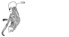
- the estimated rigid body link model 11a By applying the estimated rigid body link model 11a to the musculoskeletal model 11b as shown in FIG.
- the amount of load applied to at least one of the muscles and joints of each body part is calculated as an estimated value. Since the estimated value of the load on at least one of the muscles and joints of each body part is accumulated as the duration of the stationary posture increases, calculation using the estimated value of the load and the duration The degree of fatigue due to the object person 11 maintaining a still posture is calculated by .
- “at least one of muscles and joints” is also expressed as “muscles and/or joints.”
- the degree of fatigue based on the estimated value of the blood flow of the subject 11 in addition to the estimated value of the load applied to the muscles and/or joints.
- an example of estimating the fatigue level of the subject 11 using the estimated values of the load on the muscles and the load on the joints will be mainly described. It is also possible to estimate the degree of fatigue of the subject 11 with higher accuracy.
- the fatigue level of the subject 11 can also be estimated using an estimated value of any one of the amount of load on the muscles of the subject 11, the amount of load on the joints, and the amount of blood flow.
- the fatigue estimation system 200 estimates at least one of the amount of load on the muscles of the subject 11, the amount of load on the joints, and the amount of blood flow based on the duration of the posture. to estimate The fatigue estimation system 200 estimates the degree of fatigue of the subject 11 based on the estimated value of at least one of the estimated muscle load, joint load, and blood flow of the subject 11 .
- the estimated value of the load amount may be simply referred to as the load amount or the estimated value.
- the load is replaced with the blood flow, a large load is replaced with a decrease in blood flow, and a small load is replaced with an increase in blood flow.
- the blood flow is information for quantifying the blood flow that deteriorates when the subject 11 maintains the posture.
- the blood flow may be obtained as an absolute numerical value at the time of measurement, or may be obtained as a relative numerical value between two different time points.
- the degree of deterioration of the blood flow of the subject 11 can be estimated from the posture of the subject 11 and the relative numerical values of the blood flow at two points of time when the posture starts and ends.
- the blood flow rate of the subject can be calculated simply from the posture of the subject 11 and the duration of the posture. can be estimated.
- the musculoskeletal model 11b is used to estimate at least one of the load on the muscles, the load on the joints, and the blood flow from the posture of the subject 11. Therefore, in addition to the musculoskeletal model 11b described above, it is also possible to apply a method using actual measurement data as a method of estimating the amount of load on muscles, the amount of load on joints, and the amount of blood flow.
- This measured data is a database constructed by accumulating measured values of load on muscles, load on joints, and blood flow, which are measured for each posture, in association with the posture.
- the fatigue estimation system 200 in this case, by inputting the estimated posture of the subject 11 into the database, the measured values of the load on the muscles, the load on the joints, and the blood flow in the corresponding posture are calculated. can be obtained as output.
- the actual measurement data may be constructed using actual measurement values for each individual in consideration of individual differences in the subject 11, and statistical analysis or machine learning is performed for big data obtained from an unspecified number of subjects. It may be qualified and constructed so as to match each subject 11 by analysis processing such as.
- FIG. 2 is a block diagram showing the functional configuration of the fatigue estimation system according to the embodiment.
- the fatigue estimation system 200 in the present disclosure includes an estimation device 100, an imaging device 201, a timing device 202, a pressure sensor 203, a reception device 204, a storage device 215, a height sensor 216, a display device 205, and A recovery device 206 is provided.
- Estimation apparatus 100 includes a first acquisition unit 101, a second acquisition unit 102, a third acquisition unit 103, a fourth acquisition unit 104, a fifth acquisition unit 115, a sixth acquisition unit 116, and a posture estimation unit. 105 , a first calculation unit 106 , a second calculation unit 107 , a fatigue estimation unit 108 and an output unit 109 .
- the first acquisition unit 101 is a communication module that is connected to the imaging device 201 and acquires an image of the subject 11 from the imaging device 201 . That is, the first acquisition unit 101 is an example of an acquisition unit.
- the first acquisition unit 101 also has a function of detecting fixtures (for example, the chair 12 and the desk 13) included in the acquired image and detecting the top surface of the fixtures. That is, the first acquisition unit 101 is also an example of a detection unit that detects the top surface of furniture included in the image.
- the connection between the first acquisition unit 101 and the imaging device 201 is performed by wire or wirelessly, and the method of communication performed through the connection is not particularly limited.
- the second acquisition unit 102 is a communication module that is connected to the clock device 202 and acquires time from the clock device 202 .
- the connection between the second acquisition unit 102 and the timing device 202 is performed by wire or wirelessly, and the method of communication performed through the connection is not particularly limited.
- the third acquisition unit 103 is a communication module that is connected to the pressure sensor 203 and acquires pressure distribution from the pressure sensor 203 .
- the connection between the third acquisition unit 103 and the pressure sensor 203 is performed by wire or wirelessly, and the method of communication performed through the connection is not particularly limited.
- the fourth acquisition unit 104 is a communication module that is connected to the reception device 204 and acquires personal information from the reception device 204 .
- the connection between the fourth acquisition unit 104 and the reception device 204 is performed by wire or wirelessly, and the method of communication performed through the connection is not particularly limited.
- the fifth acquisition unit 115 is a communication module that is connected to the storage device 215 and acquires the length L (see FIG. 3B) of the lumbar skeleton 11m (see FIG. 3A) of the subject 11. That is, the first acquisition unit 101 is an example of an acquisition unit.
- the fifth acquisition unit 115 is an example of a length acquisition unit that acquires the length of the lumbar skeleton 11m.
- the fifth acquisition unit 115 acquires the length L of the lumbar spine skeleton 11m of the subject 11 stored in advance in the storage device 215 by accessing the storage device 215 .
- the fifth acquisition unit 115 transmits information about the target person 11 (identification information for identifying the target person 11 from others) as a query to the storage device 215, and as a response result to the query, the target person 11 obtain the length L of the lumbar skeleton 11 m.
- the length of the lumbar skeleton is one of the joint-connecting skeletons that extends from the back joint 11l (see FIG. 3A) of the subject 11 and connects to the lumbar joint 11n (see FIG. 3A).
- the fifth acquisition unit 115 may or may not be used depending on the extent to which the invisible part 11c (see FIG. 3A) extends to the subject.
- the fifth acquisition depends on which part of the subject 11 the boundary between the unhidden visible part 11d (see FIG. 3A) of the subject 11 and the hidden invisible part 11c as seen from the imaging device 201 corresponds.
- Part 115 may not be necessary.
- the fifth acquisition unit 115 may not be provided. That is, the fifth acquisition unit 115 is not an essential component.
- the storage device 215 may also function as a storage device (not shown) described below.
- the fifth acquisition unit 115 acquires the height H2 (see FIG. 3B) from the seat surface to the waist joint 11n when the subject 11 is seated.
- the weight of the subject 11 and the thickness of the buttocks involved in sitting are involved in the height H2.
- the fifth acquisition unit 115 transmits information about the subject 11 as a query to the storage device 215, and acquires the height H2 of the subject 11 as a response to the query.
- connection between the fifth acquisition unit 115 and the storage device 215 is performed by wire or wirelessly, and there is no particular limitation on the method of communication performed via the connection.
- the sixth acquisition unit 116 is a communication module that is connected to the height sensor 216 and acquires the height H1 (see FIG. 3B) of the seat surface of the chair 12 on which the subject 11 sits.
- the height sensor 216 is attached to the chair 12 and detects and transmits the height H1 when the subject 11 is seated on the chair 12 .
- the sixth acquisition unit 116 receives the height H2 detected by the height sensor 216 .
- the height H2 matches the height of the waist joint 11n of the subject 11 by combining with the height H1. That is, it can be said that the fifth acquisition unit 115 and the sixth acquisition unit 116 receive the height H2 and the height H1, respectively, and acquire the height of the waist joint 11n. Therefore, it can be said that the fifth acquisition unit 115 and the sixth acquisition unit 116 together constitute an example of the height acquisition unit.
- the height acquisition unit may also be implemented by a processing unit or the like that acquires an image of the subject 11 sitting and calculates the height of the waist joint 11n of the subject 11 from the image.
- the image may be acquired by the imaging device 201, but depending on the positional relationship between the imaging device 201 and the subject 11, the waist joint 11n may not appear in the image.
- the subject 11 is guided in advance to move to a range that can be captured in the image, and is seated on the chair 12 within this range. You can also
- connection between the sixth acquisition unit 116 and the height sensor 216 is performed by wire or wirelessly, and there is no particular limitation on the method of communication performed through the connection.
- the posture estimation unit 105 is a processing unit realized by executing a predetermined program using a processor and memory.
- the posture of the subject 11 is estimated by the processing of the posture estimation unit 105 based on the image acquired by the first acquisition unit 101 and the pressure distribution acquired by the third acquisition unit 103 .
- the first calculation unit 106 is a processing unit realized by executing a predetermined program using a processor and memory. Based on the estimated posture of the subject 11 and the personal information acquired by the fourth acquisition unit, the amount of load applied to each muscle and/or joint is calculated by the processing of the first calculation unit 106 .
- the second calculation unit 107 is a processing unit realized by executing a predetermined program using a processor and memory. Through the processing of the second calculation unit 107, the amount of recovery from fatigue in each muscle and/or joint is calculated based on the estimated amount of change in the posture of the subject.
- the fatigue estimation unit 108 is a processing unit realized by executing a predetermined program using a processor and memory. Fatigue estimation section 108 uses the posture estimated by posture estimation section 105 and the time acquired by second acquisition section 102 to estimate the degree of fatigue of subject 11 based on the duration of the posture estimated. presume.
- the output unit 109 is a communication module that is connected to the display device 205 and the recovery device 206 and outputs the content based on the fatigue level estimation result by the estimation device 100 to the display device 205 and the recovery device 206 .
- the connection between the output unit 109 and the display device 205 or the recovery device 206 is performed by wire or wirelessly, and the method of communication performed through the connection is not particularly limited.
- the imaging device 201 is a device that captures an image of the subject 11 and outputs an image, and is realized by a camera.
- an existing camera such as a security camera or a fixed-point camera may be used in the space where the fatigue estimation system 200 is applied, or a dedicated camera may be newly provided.
- Such an imaging device 201 is an example of an information output device that outputs an image as information about the position of the body part of the subject 11 . Therefore, the information to be output is an image, and is information including the positional relationship of the body parts of the subject 11 projected on the imaging device.
- the clock device 202 is a device that measures time and is implemented by a clock.
- the clock device 202 can transmit time to the connected second acquisition unit 102 .
- the time measured by the timer 202 may be absolute time or relative elapsed time from a starting point.
- the timing device 202 can be realized in any form as long as it can measure the time between two points of time when the target person 11 is detected to be still and when the degree of fatigue is estimated (that is, the duration of the stationary posture). good.
- the pressure sensor 203 is a sensor having a detection surface, and measures the pressure applied to each of the unit detection surfaces that divide the detection surface into one or more. The pressure sensor 203 thus measures the pressure for each unit detection surface and outputs the pressure distribution on the detection surface. The pressure sensor 203 is provided so that the subject 11 is positioned on the detection surface.
- the pressure sensors 203 are provided on the seat surface and the backrest of the chair on which the subject 11 sits. Further, for example, the pressure sensor 203 may have a marker attached on the detection surface, and the subject 11 may be guided onto the detection surface by a display such as "Please sit on the marker.” Further, by guiding the subject 11 onto the detection surface of the pressure sensor 203 provided on a part of the floor in this manner, the pressure sensor 203 may output the pressure distribution of the subject 11 on the floor. good. Since the pressure distribution is used for the purpose of improving the accuracy of estimating the degree of fatigue, the fatigue estimation system 200 may be implemented without the pressure sensor 203 if sufficient accuracy is ensured.
- the reception device 204 is a user interface that receives input of the personal information of the subject 11, and is realized by an input device such as a touch panel or keyboard.
- the personal information includes at least one of age, sex, height, weight, muscle mass, stress level, body fat percentage, and exercise proficiency.
- the age of the target person 11 may be a specific numerical value, or may be an age group divided by 10 years such as teens, 20s, and 30s.
- the age range may be divided into two divisions based on a predetermined age, such as age and older, or other age groups.
- the gender of the subject 11 is one suitable for the subject 11, which is selected from two of male and female.
- the height and weight numerical values of the height and weight of the target person 11 are respectively accepted.
- the muscle mass the muscle composition ratio of the subject 11 measured using a body composition meter or the like is accepted.
- the stress level of the subject 11 is selected by the subject 11 himself/herself from options such as high, medium, and low as the degree of subjective stress felt by the subject 11 .
- the body fat percentage of the subject 11 is the ratio of the body fat weight to the body weight of the subject 11, and is expressed, for example, as a percentage of 100.
- the subject's 11 exercise proficiency may be quantified by a score obtained when the subject 11 executes a predetermined exercise program, or may be the status of the exercise that the subject 11 usually engages in.
- the former is quantified by, for example, the time required to perform ten spins, the time required to run 50 meters, the flight distance of a long throw, and the like.
- the latter is quantified by, for example, how many days a week you exercise or how many hours you exercise. Since the personal information is used for the purpose of improving the accuracy of estimating the degree of fatigue, the fatigue estimation system 200 may be implemented without the reception device 204 if sufficient accuracy is ensured.
- the storage device 215 is a device capable of storing information, as described above.
- the storage device 215 is implemented by a semiconductor memory, an optical disk, a magnetic disk, or the like.
- the height sensor 216 is a sensor for detecting the height of the object, as described above.
- the height sensor 216 here is configured to detect the height of the seat surface of the chair 12 .
- the display device 205 is a device for displaying the content based on the fatigue level estimation results output by the output unit 109 .
- the display device 205 displays an image showing the content based on the result of estimating the degree of fatigue using a display panel such as a liquid crystal panel or an organic EL (Electro Luminescence) panel.
- a display panel such as a liquid crystal panel or an organic EL (Electro Luminescence) panel.
- the contents displayed by the display device 205 will be described later. Further, if the fatigue estimation system 200 is configured to only reduce the degree of fatigue of the subject 11 using the recovery device 206 for the subject 11, only the recovery device 206 may be provided, and the display device 205 Not required.
- the recovery device 206 is a device that reduces the degree of fatigue of the subject 11 by promoting the subject's 11 blood circulation. Specifically, the recovery device 206 changes the arrangement of each part of the chair 12 by applying voltage, pressurizing, vibrating, heating, or the like, or by a mechanism provided in the chair 12, so that the sitting subject 11 Actively change the posture of As a result, the recovery device 206 changes the load on at least one of the muscles and joints of the subject 11 and promotes blood circulation. From the viewpoint of the blood flow, by promoting the blood circulation in this way, the influence of the deterioration of the blood flow due to the subject 11 being in a still posture is reduced, and the degree of fatigue is recovered. The recovery device 206 is pre-applied or contacted to the appropriate body part of the subject 11, depending on the configuration of the device.
- the fatigue estimation system 200 is configured to display only the fatigue level estimation result to the subject 11, only the display device 205 is required, and the recovery device 206 is not essential.
- FIG. 3A is a first diagram illustrating posture estimation according to the embodiment.
- FIG. 3B is a second diagram illustrating posture estimation according to the embodiment.
- 3A and 3B show a subject 11 sitting on a chair 12 and working with a work target (not shown) placed on a desk 13 .
- 3A and 3B show plan views of the subject 11 from the lateral direction of the subject 11 (the direction orthogonal to the plane in which the subject 11, the chair 12, and the desk 13 are arranged).
- a part of the subject 11 may be positioned behind the desk 13 as viewed from the imaging device 201. Therefore, it is difficult to estimate the posture of such an invisible part 11c in the image captured by the image capture device 201 .
- the angle 11x formed by the lumbar skeleton 11m and the thigh skeleton 11o is an important part of determining the posture of the trunk portion.
- the thigh skeleton 11o is often included in the non-visible region, and many situations occur in which it is difficult to estimate the angle 11x.
- the thigh skeleton 11o is likely to form a predetermined angle with the horizontal plane according to a certain rule. It has been found that it is possible to estimate the extending direction of the femoral skeleton 11o from the end.
- the above-mentioned certain rule is, for example, when the subject 11 is in a sitting position, the extension direction of the femoral skeleton 11o is nearly parallel to the horizontal plane (the predetermined angle is 0 degrees), that is, the predetermined angle is ⁇
- the angle should be within the range of 10 degrees to 10 degrees.
- the certain rule is, for example, when the subject 11 is in a standing position, the direction in which the femoral skeleton 11o extends is nearly perpendicular to the horizontal plane (the predetermined angle is 90 degrees), that is, the predetermined angle is The angle should be within the range of 80 degrees to 100 degrees.
- the certain rule is, for example, when the subject 11 is lying down, the extending direction of the femoral skeleton 11o is nearly parallel to the horizontal plane (the predetermined angle is 0 degrees), that is, the predetermined angle is The angle should be within the range of -10 degrees to 10 degrees. It should be noted that the above-described angular range regarding the predetermined angle is an example, and a wider angular range may be applied according to the habit of posture of the subject 11 or the like. Moreover, there is no directivity in such a relative angular relationship, and the above 0 degrees is the same as 180 degrees. Similarly, 90 degrees above is the same as 270 degrees. That is, in this description, even if a multiple of 180 degrees is added to or subtracted from the predetermined angle, it is treated as the same as the predetermined angle.
- the thigh skeleton 11o is used as an example, but any skeleton that can determine a predetermined angle with respect to the horizontal plane according to a certain rule can also be used as the invisible part 11c.
- the posture estimation target here is not limited to the thigh skeleton 11o.
- the top surface of furniture such as the desk 13 is used to detect the horizontal plane.
- the rectangular top surface becomes a rectangle with right angles as it approaches the direction orthogonal to the imaging direction, and becomes a trapezoidal shape with a larger difference in length between the upper and lower bases as it approaches the direction parallel to the imaging direction.
- the fixtures used for detecting the horizontal plane may be fixtures around the target person 11 .
- fixtures other than the desk 13 may be used as long as the fixtures are included in the image together with the subject 11 .
- the upper surface of the storage can be detected as the top surface and used as a horizontal plane.
- the invisible part 11c includes the thigh skeleton 11o and the joints and skeletons on the toe side, as indicated by the dashed lines and white circles included in the rigid body link model 11a in the figure.
- the visible part 11d includes the waist joint 11n, and the joints and skeleton closer to the head than the waist joint 11n, as indicated by solid lines and black circles included in the rigid body link model 11a in the figure.
- the invisible part 11c includes the lumbar skeleton 11m, the lumbar joint 11n, the thigh skeleton 11o, and the joints and skeletons on the toe side.
- the visible part 11d includes the back joint 11l included in the rigid body link model 11a in the figure, and the joints and skeleton on the head side thereof.
- the posture of the invisible part 11c is estimated so that the thigh skeleton 11o extends from the estimated position of the waist joint 11n so as to be parallel to the horizontal plane (chain line) estimated from the desk surface 13a, , it is possible to easily estimate the angle 11x.
- the estimation of the posture of the invisible part 11c is performed only for some estimable parts. Other parts (knee joints, etc.) may be ignored or estimated by another method.
- FIG. 4A is a flowchart showing a fatigue level estimation method according to the embodiment. Also, FIG. 4B is a sub-flow chart showing details of some steps according to the embodiment.
- the fatigue estimation system 200 first acquires the personal information of the subject 11 (step S101). Acquisition of personal information is performed by the target person 11 himself/herself or an administrator or the like who manages the fatigue level of the target person 11 by inputting to the reception device 204 .
- the input personal information of the subject 11 is stored in a storage device or the like (not shown), and is read out and used when estimating the degree of fatigue.
- the fatigue estimation system 200 detects the subject 11 using the imaging device 201 (step S102). Detection of the subject 11 is performed by determining whether or not the subject 11 has entered the angle of view of the camera, which is the imaging device 201 .
- the target person 11 may be a specific target person 11, or may be a person from among an unspecified number of people who enters the angle of view of the camera. When the target person 11 is selected from an unspecified number of people, the input of personal information may be omitted. Further, when detecting a specific target person 11, a step of specifying the target person 11 by image recognition or the like is added.
- the target person 11 inputs personal information, grasps the detection area by the imaging device 201, and enters the detection area to estimate the fatigue level. Therefore, image recognition or the like is not required, and the degree of fatigue is estimated by adding personal information.
- step S102 When the fatigue estimation system 200 determines that the target person 11 has not been detected (No in step S102), it repeats step S102 until the target person 11 is detected.
- the image output by the imaging device 201 is acquired by the first acquisition unit 101 (step S103, an example of an acquisition step).
- the estimation device 100 estimates the posture of the subject 11.
- the posture estimation unit 105 estimates the posture of the subject 11 based on the acquired image and pressure distribution (posture estimation step S106).
- posture estimation step S106 is executed according to the sub-flowchart shown in FIG. 4B.
- the first acquisition unit 101 detects furniture (desk 13 in this case) in the acquired image, and detects its top surface (desk top surface 13a) (step S106a). This allows estimation of the direction parallel to the horizontal plane within the image.
- the posture estimation unit 105 estimates the posture of the visible part 11d based on the subject included in the image (step S106b). As a result, the positions of joints and skeletons included in the visible part 11d are estimated.
- the posture estimation unit 105 estimates the posture of the invisible part 11c based on the detected top surface (step S106c). Here, for example, the position of the thigh skeleton 11o is estimated. Then, the posture estimation unit 105 corrects the estimated posture (postures of the visible part 11d and the invisible part 11c) based on the pressure distribution acquired by the third acquisition unit 103 (step S106d).
- Posture correction based on pressure distribution is performed, for example, as follows.
- the pressure distribution is used, for example, when biased pressure is applied, to correct the estimated pose to form that bias.
- the first calculator 106 calculates the amount of load on each muscle and/or joint of the subject 11 from the posture estimation result.
- the personal information obtained in advance is used to correct and calculate the load amount (step S107).
- the estimation of the posture of the subject 11 is as described with reference to FIG. 1B, and the calculation of the amount of load is as described with reference to FIG. 1C, so detailed description thereof will be omitted.
- peak values may be based on the subject's 11 gender. Also, if the sex of the subject 11 is male, the amount of load may be small, and if the sex of the subject 11 is female, the amount of load may be large. Alternatively, the smaller the height and weight of the subject 11, the smaller the load, and the larger the height and weight, the larger the load.
- the load amount may be reduced as the composition ratio of the subject 11 has a large muscle mass, and the load amount may be increased as the composition ratio of the muscle mass of the subject 11 is small.
- the duration of the stationary posture of the subject 11 is measured based on the time acquired by the second acquisition unit 102 (step S108).
- the fatigue estimating unit 108 adds the load amount calculated above each time the duration time passes by the unit time, and estimates the degree of fatigue of the subject 11 at this point (fatigue estimation step S109).
- the processes of step S108 and fatigue estimation step S109 are continued until the target person 11 is released from the stationary state. Specifically, it is determined whether or not the stationary state has been released, depending on whether or not the orientation estimated by the orientation estimation unit 105 has changed from a static orientation (step S110).
- step S110 If it is not determined that the stationary state has been released (No in step S110), the process returns to step S108, measures the duration, proceeds to fatigue estimation step S109, adds the load amount, and continues as long as the stationary posture continues.
- the degree of fatigue of the subject 11 is accumulated. That is, the fatigue estimating unit 108 repeats step S108 and fatigue estimating step S109 to estimate the fatigue level of the subject 11 using a fatigue degree increasing function having a slope corresponding to the calculated load amount with respect to the duration time. Estimate degrees. Therefore, the greater the calculated load amount, the greater the degree of fatigue of the subject 11 that increases per unit time.
- the fatigue level of the subject 11 is initialized (set to 0) at the start timing of the stationary posture, which is the starting point.
- the posture estimation unit 105 calculates the amount of change in posture from the original stationary state posture to the current posture.
- the amount of change in posture is calculated for each individual muscle and/or joint, similar to the amount of load described above.
- the second calculation unit 107 calculates the amount of recovery, which is the degree of recovery from fatigue, based on the amount of change in posture (step S111).
- the change time which is the time during which the posture of the subject 11 continues to change, is measured (step S112).
- the relationship between the recovery amount and the change time is the same as the relationship between the load amount and the duration time, and the recovery amount of the subject 11 is integrated as long as the posture change continues. That is, the fatigue estimating unit 108 estimates the fatigue level of the subject 11 by subtracting the recovery amount each time the unit time elapses at the timing when the posture of the subject 11 changes (step S113).
- steps S111, S112, and S113 are continued until the posture of the subject 11 is stationary. Specifically, whether or not the posture estimated by the posture estimation unit 105 is a static posture is determined based on whether or not the subject 11 is detected to be still (step S114). If the subject 11 is not detected still (No in step S114), return to step S111 to calculate the amount of recovery, proceed to step S112 to measure the change time, and proceed to step S113 to subtract the amount of recovery. Then, as long as the posture change is continued, the fatigue level of the target person 11 is accumulated so as to recover.
- the fatigue estimating unit 108 repeats steps S111, S112, and S113, and uses a decreasing function of the degree of fatigue having a slope corresponding to the calculated recovery amount with respect to the change time.
- Estimate fatigue Since the recovery amount of the fatigue level depends on the amount of change in posture, the greater the amount of change in posture, the greater the fatigue level of the subject 11, which decreases per unit time.
- step S114 if the subject 11 is detected to be stationary (Yes in step S114), the process returns to step S105, and the posture and fatigue level are estimated again for a new stationary posture.
- the fatigue estimation system 200 since the fatigue level of the subject 11 is calculated in consideration of the duration time in the stationary posture based on the image, the burden on the subject 11 is small, and more accurate The degree of fatigue of the subject 11 can be estimated.
- FIG. 5A is a diagram showing a subject standing still in Posture A.
- FIG. 5B is a diagram showing the subject standing still in the posture B. As shown in FIG.
- the subject 11 shown in FIGS. 5A and 5B is in a stationary posture in a seated position on a chair 12, similar to that shown in FIG. 1A.
- FIGS. 5A and 5B there are actually tables, PCs, etc., which are not shown, but only the subject 11 and the chair 12 are shown here.
- the stationary posture of the subject 11 shown in FIG. 5A is posture A in which the load on the shoulders is relatively large.
- the stationary posture of the subject 11 shown in FIG. 5B is posture B in which the load on the shoulder is relatively small.
- FIG. 6A is a first diagram illustrating accumulation of estimated fatigue level of a subject according to the embodiment.
- FIG. 6B is a second diagram illustrating accumulation of the subject's fatigue level estimated according to the embodiment.
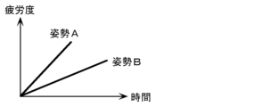
- posture A is a posture with a larger load than posture B. Therefore, for example, in certain muscles of the subject 11 (here, muscles related to shoulder movement), the load amount of posture A (slope of the straight line of posture A) is greater than the load of posture B (slope of the straight line of posture B). is also big. Therefore, in the posture A, the target person 11 accumulates (accumulates) a larger degree of fatigue in a shorter time than in the case of standing still in the posture B.
- the degree of fatigue of the subject 11 is an increasing function with a positive slope corresponding to the load amount in the posture A, as in FIG. is estimated as the accumulation (addition) of the degree of fatigue by , and the accumulation (addition) turns to recovery (decrease) at the change point where the subject 11 begins to change the posture.
- the degree of fatigue of the subject 11 is determined by a decreasing function with a negative slope corresponding to the amount of change in posture. It recovers (decreases) by the amount shown as the change width inside.
- the fatigue level of the subject 11 is an increasing function with a positive slope corresponding to the load amount of the posture B, and is estimated as accumulation (addition) of the fatigue level. be done.
- the degree of fatigue of the subject 11 is estimated in which accumulation and recovery are reflected according to the rest and change of the posture of the subject 11 .
- FIG. 7 is a first diagram showing a display example of estimation results according to the embodiment.
- FIG. 8 is a second diagram showing a display example of estimation results according to the embodiment.
- the result of estimating the degree of fatigue of the subject 11 can be displayed using the display device 205 and fed back.
- a display device 205 integrally displays a doll simulating the subject 11 and fatigue levels of the subject 11's shoulders, back, and main parts.
- the fatigue level of the shoulder is indicated as "stiff shoulder”
- the fatigue of the back is indicated as “back pain”
- the fatigue of the lower back is indicated as "low back pain”.
- the fatigue levels of the subject 11 at three locations are displayed at once, and the fatigue levels at these three locations are estimated from images captured at once. That is, the estimating apparatus 100 detects muscles and/or joints in each of a plurality of body parts including a first part (eg, shoulder), a second part (eg, back), and a third part (eg, waist) of the subject 11. , the degree of fatigue is estimated from one posture of the subject 11 . Therefore, even if the posture of the subject 11 is constant, the degree of fatigue accumulated in muscles and/or joints differs for each body part. can be estimated.
- a first part eg, shoulder
- a second part eg, back
- a third part eg, waist
- the load amount is calculated for each muscle and/or joint of the subject 11. Therefore, if there is no processing resource limitation, each muscle and/or joint fatigue can be estimated. Therefore, there is no limit to the number of body parts whose fatigue levels are estimated from images captured at one time, and the number may be one, two, or four or more.
- the estimating device 100 calculates the load amount for each of a plurality of body parts, and calculates the degree of fatigue (the degree of stiff shoulders) of the first part based on the load amount calculated for the first part in one posture of the subject 11. , the fatigue level of the second part (the above-mentioned back pain level) due to the load amount calculated at the second part, and the fatigue level of the third part (the above-mentioned low back pain level) due to the load amount calculated at the third part, can be estimated.
- the degree of stiff shoulders is estimated from the amount of load on the trapezius muscle
- the degree of back pain is estimated from the degree of fatigue of the latissimus dorsi muscle
- the degree of low back pain is estimated from the amount of load on the lumbar paraspinal muscles.
- one fatigue level may be estimated from the load of one muscle and / or joint, but one fatigue level is estimated from the combined load of a plurality of muscles and / or joints.
- the degree of stiff neck that is, one degree of shoulder fatigue
- the degree of stiff neck may be estimated from the average value of the loads of the trapezius muscle, the levator scapula muscle, the rhomboid muscle, and the deltoid muscle.
- a more realistic fatigue degree can be estimated by weighting the amount of load on muscles and/or joints that have a particularly large effect on the degree of fatigue of the relevant body part, instead of using a simple average value. Estimates may be made.
- the degree of fatigue estimated in this way may be indicated as a relative position on a reference meter with a minimum value of 0 and a maximum value of 100 as shown.
- a reference value is provided at a predetermined position on the reference meter.
- Such a reference value is set to the relative position (or before and after) of the degree of fatigue at which subjective symptoms such as pain may occur in a general subject 11 quantified in advance by an epidemiological survey or the like. Therefore, different reference values may be set according to the degree of fatigue of each body part.
- the display device 205 may display a warning to the target person 11 as an estimation result when the estimated fatigue level of the target person 11 reaches the reference value.
- the reference value here is an example of the first threshold.
- the display device 205 may display a specific coping method such as "Recommend taking a break" as shown in the drawing.
- the display device 205 displays the currently estimated fatigue level of the target person 11 for the target person 11 when the estimated fatigue level of the target person 11 reaches the reference value.
- a recommended posture with less load on the body part that reaches the reference value may be displayed.
- the reference value here is an example of the second threshold, and may be the same as or different from the first threshold.
- the displayed recommended posture may be accompanied by specific notes such as "put your weight on the back of the chair” and "sit deeply on the seat” together with the doll that assumes that posture.
- the fatigue estimation system 200 actively activates the subject 11. It is also possible to consider a configuration that recovers the degree of fatigue of the user. Specifically, the recovery device 206 shown in FIG. 2 operates to recover the degree of fatigue of the subject 11 .
- the specific configuration of the recovery device 206 is as described above, so a description thereof will be omitted.
- the reference value here is an example of the third threshold, and may be the same as or different from either the first threshold or the second threshold.
- the fatigue estimation system 200 in the first aspect of the present embodiment is a fatigue estimation system 200 that estimates the fatigue level of the subject 11 whose part is hidden when viewed from the imaging device 201,
- An imaging device 201 that captures an image including the target person 11 and fixtures (desk 13, etc.) around the target person 11;
- a detection unit (for example, included in the first acquisition unit 101 as one of the functions) that detects the top surface of fixtures (such as the desk surface 13a) included in the acquired image, and a posture that estimates the posture of the subject 11
- the estimating unit 105 estimates the posture of the visible part 11d of the target person 11 that is not hidden when viewed from the imaging device 201 based on the target person 11 included in the image, and based on the detected top surface , a posture estimation unit 105 that estimates the posture of the invisible part 11c of the target person 11 that is hidden when viewed from the imaging device 201, and the fatigue level of the target person 11 is estimated based on the estimated posture of the target person 11. and
- Such a fatigue estimation system 200 can estimate the orientation of the invisible part 11c based on the top surface of the furniture. Therefore, the fatigue level of the subject 11 can be estimated based on the estimated posture of the invisible part 11c, compared to the case where the invisible part 11c exists and the fatigue level related to the invisible part is not estimated. Therefore, the degree of fatigue can be estimated with higher accuracy.
- the visible part 11d includes the waist joint 11n of the subject 11, and the invisible part 11c is the thigh of the subject 11, which is a skeleton extending from the waist joint 11n.
- the posture estimating unit 105 which includes the skeleton 11o, determines the extension direction of the thigh skeleton 11o extending in a direction forming a predetermined angle with respect to the top surface from the position of the waist joint 11n included in the estimated posture of the visible part 11d.
- the fatigue estimation system according to the first aspect, which estimates the
- the estimated thigh Since the fatigue level of the subject 11 can be estimated based on the posture of the partial skeleton 11o, the fatigue level can be estimated with higher accuracy.
- the visible part 11d includes the back joint 11l of the subject 11, and the invisible part 11c is the lumbar skeleton 11m of the subject 11, which is a skeleton extending from the back joint 11l.
- the fatigue estimation system 200 further includes a lumbar joint 11n of the subject 11 connected to the back joint 11l via and a thigh skeleton 11o of the subject 11, which is a skeleton extending from the lumbar joint 11n.
- a fifth acquisition unit 115 (hereafter, length acquisition unit) that acquires the length
- a fifth acquisition unit 115 and a sixth acquisition unit 116 (hereafter, height acquisition unit) that acquire the height of the waist joint 11n.
- the posture estimation unit 105 determines that the position of the back joint 11l included in the estimated posture of the visible part 11d is within the range of the length of the acquired lumbar spine skeleton 11m and matches the height of the acquired waist joint 11n.
- the position of the waist joint 11n is estimated, and the extension direction of the thigh skeleton 11o extending in a direction forming a predetermined angle with respect to the top surface is estimated from the estimated position of the waist joint 11n. It is a fatigue estimation system.
- the visible part 11d includes the back joint 11l of the subject 11, and the non-visible part 11c is connected to the back joint 11l via the lumbar skeleton 11m of the subject 11, which is a skeleton extending from the back joint 11l.
- the waist joint 11n of the person 11 and the thigh skeleton 11o of the subject 11, which is a skeleton extending from the waist joint 11n are included, the estimated posture of the waist joint 11n and the thigh skeleton 11o is used to determine the posture of the subject 11. can be estimated, the fatigue level can be estimated with higher accuracy.
- the predetermined angle is an angle within the range of 80 degrees to 100 degrees. It is a fatigue estimation system.
- the fifth aspect of the present embodiment is the fatigue estimation system according to the fourth aspect, in which the predetermined angle is 90 degrees when the subject 11 is standing.
- the predetermined angle is an angle within the range of -10 degrees to 10 degrees, either of the second or third aspect A fatigue estimation system according to one aspect.
- the seventh aspect of the present embodiment is the fatigue estimation system according to the sixth aspect, in which the predetermined angle is 0 degrees when the subject 11 is in a sitting position.
- the fixture is the desk 13 used by the subject 11, and the top surface is the desk surface 13a of the desk 13, any one of the first to seventh aspects.
- a fatigue estimation system according to one aspect.
- the posture of the invisible part 11c can be estimated using the desk surface 13a as the top surface of the desk 13 as furniture.
- the invisible part 11c is hidden by furniture when viewed from the imaging device 201.
- the fatigue estimation system according to any one aspect of the first to eighth aspects, be.
- the posture of the invisible part 11c of the target person 11 hidden behind the furniture can be estimated using the top surface of the fixture.
- an information output device for example, an imaging device 201 that outputs information about the position of the body part of the subject 11, and information (for example, an image) output by the information output device.
- An estimation device 100 that estimates the posture and estimates the degree of fatigue of the subject 11 based on the estimated posture and the duration of the posture.
- the information output device is the imaging device 201 that captures an image of the subject 11 and outputs an image as information about the position of the body part, and the estimation device 100 outputs the image based on the image output by the imaging device 201.
- the posture of the subject 11 may be estimated.
- Such a fatigue estimation system 200 can estimate the degree of fatigue of the subject 11 using the image output by the imaging device 201 .
- the posture of the subject 11 estimated from the output image is used. Specifically, the amount of load on the muscles, the amount of load on the joints, and the deterioration of blood flow due to the maintenance of a certain static posture are calculated from the duration of time spent in the static posture in which the posture of the subject 11 is still. Accumulation of fatigue accompanying such as is quantified as a degree of fatigue.
- the degree of fatigue of the subject 11 is calculated based on the image, taking into account the duration of the stationary posture, so that the burden on the subject 11 is reduced, and more accurate It is possible to estimate the degree of fatigue of the subject 11 in a static posture.
- the estimating apparatus 100 calculates the amount of load on at least one of the muscles and joints of the subject 11 used to maintain the estimated posture using the musculoskeletal model 11b, and increases the degree of fatigue with respect to the duration.
- the fatigue level may be estimated using a function, and in the increasing function used for estimating the fatigue level, the greater the calculated load amount, the greater the fatigue level that increases per unit time.
- the load amount for at least one of individual muscles and joints is calculated using the musculoskeletal model 11b.
- the degree of fatigue of the subject 11 can be easily estimated by an increasing function whose slope is the amount of load calculated in this manner. Therefore, it is possible to easily estimate the degree of fatigue of the subject 11 with higher accuracy.
- the estimating apparatus 100 calculates the load amount of at least one of muscles and joints in each of two or more body parts including the first part and the second part among the body parts of the subject 11, In one posture of 11, at least a first fatigue level of the first part based on the load amount calculated for the first part and a second fatigue level of the second part based on the load amount calculated for the second part are calculated. can be estimated.
- the degree of fatigue for two or more body parts of the subject 11 with one imaging. There is no need to perform measurements for estimating fatigue levels for each body part, and the fatigue levels of a plurality of body parts can be estimated quickly and substantially simultaneously.
- the degree of fatigue estimated substantially at the same time makes it possible to easily specify the body part of the subject 11 that is likely to get fatigued, which is effective when devising a coping method for recovering from the degree of fatigue. Therefore, it is possible to quickly and effectively estimate the degree of fatigue of the subject 11 .
- the estimation apparatus 100 estimates the fatigue level using a decreasing function of the fatigue level with respect to time, and the decreasing function used for estimating the fatigue level has a large amount of change in posture.
- the degree of fatigue that decreases per unit time may be increased as much as possible.
- the load on at least one of the muscles and joints is changed, and the recovery of the fatigue level by improving the blood flow is reflected in the estimated fatigue level. be done. Therefore, it is possible to more accurately estimate the degree of fatigue of the target person 11 in relation to the position of the body part of the target person 11 in the still posture.
- the fatigue estimation system 200 further includes a display device that displays a warning to the target person 11 as an estimation result when the fatigue level of the target person 11 estimated by the estimation device 100 reaches the first threshold. 205 may be provided.
- the target person 11 and the like can know from the warning displayed on the display device 205 that the fatigue level of the target person 11 has reached the first threshold.
- the target person 11 can reduce the possibility of suffering from poor physical condition, injury, accident, etc. due to fatigue by coping with the accumulated fatigue level according to the displayed warning. Therefore, the degree of fatigue estimated with higher accuracy is used to suppress the discomfort caused by the fatigue of the subject 11 .
- the fatigue estimation system 200 may be triggered by the fact that the degree of fatigue of the subject 11 estimated by the estimation device 100 has reached the second threshold, and the load on the subject 11 may be more than the posture.
- a display device 205 that displays a few recommended postures may be provided.
- the target person 11 and the like can cope with the fatigue level of the target person 11 that has reached the second threshold by using the recommended posture displayed on the display device 205 .
- the recommended posture By changing to the recommended posture, it is expected that the degree of fatigue of the subject 11 will recover, so that the subject 11 can suppress accumulation of fatigue without being particularly conscious of it. Therefore, the degree of fatigue estimated with higher accuracy is used to suppress the discomfort caused by the fatigue of the subject 11 .
- the fatigue estimation system 200 further accelerates the blood circulation of the subject 11 when the fatigue level of the subject 11 estimated by the estimation device 100 reaches the third threshold.
- a recovery device 206 may be provided to reduce the degree of fatigue of the.
- the recovery device 206 since the recovery device 206 is expected to recover the degree of fatigue of the subject 11, the subject 11 can suppress the accumulation of fatigue without being particularly conscious of it. Therefore, the degree of fatigue estimated with higher accuracy is used to suppress the discomfort caused by the fatigue of the subject 11 .
- the fatigue estimation system 200 further includes a pressure sensor 203 that outputs a pressure distribution indicating the distribution of pressure applied on the detection surface, and the estimation device 100 detects the pressure distribution output by the pressure sensor 203. Based on this, the estimated posture of the subject 11 may be corrected, and the load amount for maintaining the corrected posture may be calculated.
- the pressure distribution output by the pressure sensor 203 can be used to estimate the posture of the subject 11 . Therefore, the posture of the subject 11 can be estimated with high accuracy by correcting the pressure distribution. Therefore, the degree of fatigue of the subject 11 can be estimated with higher accuracy.
- the fatigue estimation system 200 further includes personal information including at least one of age, sex, height, weight, muscle mass, stress level, body fat percentage, and exercise proficiency level of the subject 11. Equipped with a receiving device 204 that receives input, the estimating device 100 may correct the load amount based on the personal information received by the receiving device 204 when calculating the load amount for maintaining the estimated posture. good.
- the personal information received by the receiving device 204 can be used to calculate the amount of load. Therefore, the load amount in the stationary posture can be calculated with high accuracy by correction using the personal information. Therefore, the degree of fatigue of the subject 11 can be estimated with higher accuracy.
- the estimation device 100 is an estimation device 100 that estimates the fatigue level of the target person 11 whose part is hidden when viewed from the imaging device 201.
- a first acquisition unit 101 (hereinafter referred to as an image acquisition unit) that acquires an image including fixtures (desk 13, etc.) around the person 11 and the target person 11; etc.) (for example, included in the first acquisition unit 101 as one of the functions), and a posture estimation unit 105 for estimating the posture of the subject 11, which is included in the image. Based on this, the posture of the visible part 11d of the subject 11 that is not hidden when viewed from the imaging device 201 is estimated, and based on the detected top surface, the hidden subject 11 when viewed from the imaging device 201 is estimated. and a posture estimating unit 108 for estimating the subject's degree of fatigue based on the estimated subject's posture.
- Such an estimating device 100 can achieve the same effects as the fatigue estimating system 200 described above in combination with the imaging device 201 .
- a first acquisition unit 101 that acquires information about the positions of body parts of the subject 11, and a posture estimation unit 105 that estimates the posture of the subject 11 based on the information acquired by the first acquisition unit 101. and a fatigue estimation unit 108 that estimates the degree of fatigue based on the duration of the posture estimated by the posture estimation unit 105 .
- Such an estimation device 100 can estimate the degree of fatigue of the subject 11 using information such as acquired images.
- the posture of the subject 11 estimated from the acquired image or the like is used. Specifically, the load on at least one of the muscles and joints and the deterioration of blood flow due to the maintenance of a constant static posture from the duration of time elapsed in the static posture in which the posture of the subject 11 is static. The accumulation of fatigue associated with this is quantified as the degree of fatigue. In this way, since the estimation device 100 calculates the fatigue level of the subject 11 in consideration of the duration of the static posture, it is possible to more accurately estimate the fatigue level of the subject 11 in the static posture. can.
- the fatigue estimation method in the eleventh aspect of the present embodiment is a fatigue estimation method for estimating the degree of fatigue of the target person 11 whose part is hidden when viewed from the imaging device 201.
- An image including fixtures (desk 13, etc.) around the person 11 and the subject 11 is acquired, the top surface of the fixture (desk top 13a, etc.) included in the acquired image is detected, and the subject 11 included in the image is detected.
- the posture of the invisible part 11 c of 11 is estimated, and the degree of fatigue of the subject 11 is estimated based on the estimated posture of the subject 11 .
- Such a fatigue estimation method can achieve the same effects as the fatigue estimation system 200 described above.
- an acquisition step (step S103 or the like) of acquiring information about the positions of body parts of the subject 11, and a posture estimation step S106 of estimating the posture of the subject 11 based on the information acquired in the acquisition step. and a fatigue estimation step S109 for estimating the degree of fatigue based on the duration of the posture estimated in the posture estimation step S106.
- Such a fatigue estimation method has the same effects as the estimation device 100 described above.
- the processing executed by a specific processing unit may be executed by another processing unit.
- the order of multiple processes may be changed, and multiple processes may be executed in parallel.
- the fatigue estimation system or estimation device in the present disclosure may be realized by a plurality of devices each having a part of a plurality of components, or may be realized by a single device having all of the plurality of components. good. Also, some of the functions of a component may be implemented as functions of another component, and each function may be distributed among the components in any way.
- the present disclosure includes any form having a configuration in which substantially all of the functions that can realize the fatigue estimation system or the estimating device of the present disclosure are provided.
- each component may be realized by executing a software program suitable for each component.
- Each component may be realized by reading and executing a software program recorded in a recording medium such as a hard disk or a semiconductor memory by a program execution unit such as a CPU or processor.
- each component may be realized by hardware.
- each component may be a circuit (or integrated circuit). These circuits may form one circuit as a whole, or may be separate circuits. These circuits may be general-purpose circuits or dedicated circuits.
- the posture of the subject is estimated from the image using the rigid link model generated by image recognition, the load amount is calculated from the estimated posture of the subject, and based on the load amount and the duration time.
- the method of estimating the degree of fatigue is not limited to this. Any existing method may be used as a method of estimating the posture of the subject from the image, and any existing method may be used as a method of estimating the amount of load from the posture of the subject.
- FIG. 9 is a diagram explaining posture estimation according to a modification of the embodiment.
- the posture of the subject 11 is estimated using a sensor module 207 including a position sensor 207a and an electric potential sensor 207b.
- a plurality of sensor modules 207 are attached to the subject 11 here, but the number of sensor modules 207 attached to the subject 11 is not particularly limited. Only one sensor module 207 may be attached to the subject 11 .
- the mounting style of the sensor module 207 is not particularly limited, and any style may be used as long as the position of a predetermined body part of the subject 11 can be measured.
- the subject 11 is equipped with a plurality of sensor modules 207 by wearing a costume to which a plurality of sensor modules 207 are attached.
- the sensor module 207 is a device that is attached to a predetermined body part of the subject 11 and outputs information indicating the result of detection or measurement in conjunction with the predetermined body part. Specifically, the sensor module 207 outputs the position sensor 207a that outputs the position information regarding the spatial position of the predetermined body part of the subject 11, and the potential information that indicates the potential at the predetermined body part of the subject 11. It has a potential sensor 207b. Although the figure shows the sensor module 207 having both the position sensor 207a and the potential sensor 207b, the potential sensor 207b is not essential if the sensor module 207 has the position sensor 207a.
- the position sensor 207a in such a sensor module 207 is an example of an information output device that outputs position information as information relating to the position of the body part of the subject 11. Therefore, the information to be output is positional information, and is information including relative or absolute positions of predetermined body parts of the subject 11 . Also, the information to be output may include, for example, potential information.
- the potential information is information including the value of potential measured at a predetermined body part of the subject 11 . Position information and potential information will be described in detail below together with the position sensor 207a and the potential sensor 207b.
- the position sensor 207a detects a spatial relative position or an absolute position of a predetermined body part of the subject 11 to which the sensor module 207 is attached, and outputs information on the spatial position of the predetermined body part as a detection result. It is a vessel.
- the information about the spatial position includes information that can identify the position of the body part in the space as described above and information that can identify the change in the position of the body part due to body movement.
- the information about the spatial position includes information indicating the positions of the joints and the skeleton in space and changes in the positions.
- the position sensor 207a is configured by combining various sensors such as an acceleration sensor, an angular velocity sensor, a geomagnetic sensor, and a range sensor. Since the position information output by the position sensor 207a can approximate the spatial position of a predetermined body part of the subject 11, the posture of the subject 11 can be estimated from the spatial position of the predetermined body part.
- the electric potential sensor 207b is a detector that measures the electric potential at a predetermined body part of the subject 11 to which the sensor module 207 is worn and outputs information indicating the electric potential of the predetermined body part, which is the measurement result.
- the potential sensor 207b is a measuring instrument that has a plurality of electrodes and measures a potential generated between the plurality of electrodes using an electrometer.
- the potential information output by the potential sensor indicates the potential generated at a predetermined body part of the subject 11, and since the potential corresponds to the action potential of the muscle at the predetermined body part, the activity of the predetermined body part is detected. It is possible to improve the estimation accuracy of the posture of the subject 11 estimated from the potential or the like.
- the fatigue estimation system in this modified example estimates the degree of fatigue of the subject 11 using the posture of the subject 11 estimated as described above. It should be noted that the processing after estimating the posture of the subject 11 is the same as in the above-described embodiment, and thus the description thereof is omitted.
- the information output device is attached to a predetermined body part of the subject 11, and outputs position information about the spatial position of the predetermined body part as information about the position of the body part of the subject 11.
- the position sensor 207a outputs, and the estimation apparatus 100 estimates the posture of the subject 11 based on the position information output from the position sensor 207a.
- the fatigue level of the subject 11 can be estimated using the position information output by the position sensor 207a.
- the posture of the subject 11 estimated from the output information is used.
- the accumulation of fatigue caused by maintaining a constant static posture is quantified as the degree of fatigue based on the duration of time elapsed in the static posture in which the posture of the subject 11 is static.
- the degree of fatigue of the subject 11 is calculated in consideration of the duration of the stationary posture. It is possible to estimate the degree of fatigue of the subject 11 in a stationary posture with less burden and with higher accuracy.
- the increasing function and decreasing function are described as linear functions, but the present invention is not limited to this.
- the increasing function may be a curvilinear function as long as the fatigue level increases with time.
- the decreasing function may be a curvilinear function as long as it is a function that decreases the degree of fatigue over time.
- the estimation device described above uses the load on muscles, the load on joints, and the blood flow estimated from the posture of the subject to estimate the degree of fatigue of the subject. As described above, it is also possible to correct the estimated value using the value measured using the measuring device to achieve more accurate estimation of the degree of fatigue. Specifically, the estimating device acquires a measured value corresponding to the estimated value, which is a measured value based on the measurement result of measuring the subject by the measuring device.
- the detection device is, for example, an electromyograph, a muscle hardness meter, a pressure gauge, a near-infrared spectrometer, etc., and obtains measured values regarding the amount of load on muscles, the amount of load on joints, and the blood flow by measurement. can be done.
- an electromyograph can estimate muscle movement corresponding to the potential based on the potential measured by potential measurement. That is, a value obtained by estimating the muscle movement can be obtained as a measurement value. Since the value obtained by estimating the movement of the muscle can be converted into the amount of load on the muscle, the estimated value of the amount of load on the muscle can be corrected by the measured value.
- the correction here is, for example, taking the average value of the estimated value and the measured value, selecting one of the estimated value and the measured value, and applying the estimated value to the correlation function between the estimated value and the measured value. and so on.
- a muscle hardness meter can estimate muscle hardness from the stress when pressure is applied to the muscle. Since the estimated muscle hardness value can be converted into the amount of load on the muscle, it can be used to correct the estimated value in the same manner as described above.
- the pressure gauge can obtain a measured value of what kind of pressure is applied to the body part of the subject. Such pressure parameters can be input into the musculoskeletal model. By inputting additional parameters such as pressure, the estimation accuracy of the musculoskeletal model is improved, and the estimated value estimated using the musculoskeletal model can be corrected with higher accuracy.
- a near-infrared spectrometer can obtain spectroscopic measurement values of the subject's blood flow.
- the estimated value may be corrected by combining the blood flow rate measured by the infrared spectrometer.
- the measured blood flow may be used when the estimated blood flow has low reliability.
- the fatigue estimation system described in the above embodiment may be used to configure a fatigue factor identification system that identifies the subject's fatigue factors.
- Conventional devices or systems for estimating the degree of fatigue as "degree of stiff shoulder” and “degree of low back pain” use muscles and joints (that is, factors It was difficult to identify the posture that Therefore, by using the fatigue estimation system according to the present disclosure, the above problem can be addressed.
- body parts where fatigue is likely to accumulate are identified as fatigue factor parts in the static posture taken by the subject.
- the fatigue factor identification system may simply identify the fatigue factor part in one static posture taken by the subject, and the estimated amount in the fatigue factor part most among the plurality of static postures taken by the subject You may also identify the fatigue factor posture with many
- a recommended posture that replaces the specified fatigue-causing posture may be presented, and a fatigue degree recovery operation using a recovery device may be performed on the fatigue-causing portion in the fatigue-causing posture.
- the fatigue factor identification system includes the fatigue estimation system described in the above embodiment and a storage device for storing information on the estimated degree of fatigue.
- a storage device may be implemented using, for example, a semiconductor memory or the like, and each main storage unit or the like constituting the fatigue estimation system may be used. good too.
- the present disclosure may be implemented as a fatigue estimation method executed by a fatigue estimation system or an estimation device.
- the present disclosure may be implemented as a program for causing a computer to execute such a fatigue estimation method, or may be implemented as a computer-readable non-temporary recording medium in which such a program is recorded. .
Landscapes
- Health & Medical Sciences (AREA)
- Life Sciences & Earth Sciences (AREA)
- Engineering & Computer Science (AREA)
- Animal Behavior & Ethology (AREA)
- Heart & Thoracic Surgery (AREA)
- Veterinary Medicine (AREA)
- Public Health (AREA)
- General Health & Medical Sciences (AREA)
- Surgery (AREA)
- Physics & Mathematics (AREA)
- Molecular Biology (AREA)
- Biophysics (AREA)
- Pathology (AREA)
- Biomedical Technology (AREA)
- Medical Informatics (AREA)
- Educational Technology (AREA)
- Developmental Disabilities (AREA)
- Social Psychology (AREA)
- Child & Adolescent Psychology (AREA)
- Psychology (AREA)
- Psychiatry (AREA)
- Hospice & Palliative Care (AREA)
- Dentistry (AREA)
- Oral & Maxillofacial Surgery (AREA)
- Measurement Of The Respiration, Hearing Ability, Form, And Blood Characteristics Of Living Organisms (AREA)
Priority Applications (1)
| Application Number | Priority Date | Filing Date | Title |
|---|---|---|---|
| JP2023564901A JP7599124B2 (ja) | 2021-11-30 | 2022-11-22 | 疲労推定システム、推定装置、及び疲労推定方法 |
Applications Claiming Priority (2)
| Application Number | Priority Date | Filing Date | Title |
|---|---|---|---|
| JP2021-194910 | 2021-11-30 | ||
| JP2021194910 | 2021-11-30 |
Publications (1)
| Publication Number | Publication Date |
|---|---|
| WO2023100718A1 true WO2023100718A1 (ja) | 2023-06-08 |
Family
ID=86612054
Family Applications (1)
| Application Number | Title | Priority Date | Filing Date |
|---|---|---|---|
| PCT/JP2022/043178 Ceased WO2023100718A1 (ja) | 2021-11-30 | 2022-11-22 | 疲労推定システム、推定装置、及び疲労推定方法 |
Country Status (2)
| Country | Link |
|---|---|
| JP (1) | JP7599124B2 (https=) |
| WO (1) | WO2023100718A1 (https=) |
Citations (3)
| Publication number | Priority date | Publication date | Assignee | Title |
|---|---|---|---|---|
| WO2021112096A1 (ja) * | 2019-12-06 | 2021-06-10 | パナソニックIpマネジメント株式会社 | 疲労推定システム、推定装置、及び疲労推定方法 |
| JP2021093037A (ja) * | 2019-12-11 | 2021-06-17 | 株式会社東芝 | 算出システム、算出方法、プログラム、及び記憶媒体 |
| JP2021103850A (ja) * | 2019-12-25 | 2021-07-15 | エヌ・ティ・ティ・コミュニケーションズ株式会社 | 監視端末及び監視方法 |
-
2022
- 2022-11-22 WO PCT/JP2022/043178 patent/WO2023100718A1/ja not_active Ceased
- 2022-11-22 JP JP2023564901A patent/JP7599124B2/ja active Active
Patent Citations (3)
| Publication number | Priority date | Publication date | Assignee | Title |
|---|---|---|---|---|
| WO2021112096A1 (ja) * | 2019-12-06 | 2021-06-10 | パナソニックIpマネジメント株式会社 | 疲労推定システム、推定装置、及び疲労推定方法 |
| JP2021093037A (ja) * | 2019-12-11 | 2021-06-17 | 株式会社東芝 | 算出システム、算出方法、プログラム、及び記憶媒体 |
| JP2021103850A (ja) * | 2019-12-25 | 2021-07-15 | エヌ・ティ・ティ・コミュニケーションズ株式会社 | 監視端末及び監視方法 |
Also Published As
| Publication number | Publication date |
|---|---|
| JP7599124B2 (ja) | 2024-12-13 |
| JPWO2023100718A1 (https=) | 2023-06-08 |
Similar Documents
| Publication | Publication Date | Title |
|---|---|---|
| JP7133779B2 (ja) | 疲労推定システム、推定装置、及び疲労推定方法 | |
| US11182599B2 (en) | Motion state evaluation system, motion state evaluation device, motion state evaluation server, motion state evaluation method, and motion state evaluation program | |
| KR102107379B1 (ko) | 3축 동작측정기를 이용한 노쇠 예측 방법, 3축 동작측정기를 이용한 노쇠 예측 시스템 및 웨어러블 노쇠 예측 장치 | |
| US11826140B2 (en) | System and method for human motion detection and tracking | |
| JP6433805B2 (ja) | 運動機能診断装置及び方法、並びにプログラム | |
| CN103596626A (zh) | 跑步方式诊断系统以及跑步方式的打分方法 | |
| JP6127873B2 (ja) | 歩行特徴の解析方法 | |
| US12161480B2 (en) | Method and device for correcting posture | |
| KR20190041081A (ko) | 인지장애 진단을 위한 vr기반 인지능력 평가시스템 | |
| JP2018121930A (ja) | 歩容の評価方法 | |
| Hotrabhavananda et al. | Evaluation of the microsoft kinect skeletal versus depth data analysis for timed-up and go and figure of 8 walk tests | |
| JP7734347B2 (ja) | 姿勢評価装置、個室ブース、及び姿勢評価方法 | |
| US20040059264A1 (en) | Footprint analyzer | |
| JP5427679B2 (ja) | 床反力計測システム及び方法 | |
| WO2023100718A1 (ja) | 疲労推定システム、推定装置、及び疲労推定方法 | |
| WO2023127203A1 (ja) | 活動量算出装置及び活動量算出方法 | |
| JP7630118B2 (ja) | 疲労推定システム、疲労推定方法、姿勢推定装置及びプログラム | |
| WO2023120064A1 (ja) | 疲労推定装置、疲労推定システム、及び疲労推定方法 | |
| KR102411882B1 (ko) | 이미지를 이용한 비대면 체력측정 시스템 | |
| Bartlett et al. | An RGB-D sensor-based instrument for sitting balance assessment | |
| JP2019005147A (ja) | 疲労度算出装置、及び、疲労度算出プログラム | |
| WO2025033200A1 (ja) | 姿勢分析装置、姿勢分析方法、及び、プログラム | |
| US20240359081A1 (en) | Information processing apparatus, method, and non-transitory computer-readable program | |
| CN115426951B (zh) | 疲劳推测系统、疲劳推测方法及程序记录介质 | |
| KR102568107B1 (ko) | 멀티 센싱 및 비전 인식을 통한 근손실 진단 시스템 |
Legal Events
| Date | Code | Title | Description |
|---|---|---|---|
| 121 | Ep: the epo has been informed by wipo that ep was designated in this application |
Ref document number: 22901151 Country of ref document: EP Kind code of ref document: A1 |
|
| WWE | Wipo information: entry into national phase |
Ref document number: 2023564901 Country of ref document: JP |
|
| NENP | Non-entry into the national phase |
Ref country code: DE |
|
| 122 | Ep: pct application non-entry in european phase |
Ref document number: 22901151 Country of ref document: EP Kind code of ref document: A1 |