WO2023100718A1 - Fatigue estimation system, estimation device, and fatigue estimation method - Google Patents
Fatigue estimation system, estimation device, and fatigue estimation method Download PDFInfo
- Publication number
- WO2023100718A1 WO2023100718A1 PCT/JP2022/043178 JP2022043178W WO2023100718A1 WO 2023100718 A1 WO2023100718 A1 WO 2023100718A1 JP 2022043178 W JP2022043178 W JP 2022043178W WO 2023100718 A1 WO2023100718 A1 WO 2023100718A1
- Authority
- WO
- WIPO (PCT)
- Prior art keywords
- subject
- fatigue
- posture
- estimated
- imaging device
- Prior art date
Links
- 238000000034 method Methods 0.000 title claims description 40
- 238000003384 imaging method Methods 0.000 claims abstract description 73
- 238000001514 detection method Methods 0.000 claims abstract description 25
- 210000000689 upper leg Anatomy 0.000 claims description 22
- 210000004705 lumbosacral region Anatomy 0.000 claims description 5
- 230000006870 function Effects 0.000 abstract description 28
- 230000036544 posture Effects 0.000 description 246
- 210000003205 muscle Anatomy 0.000 description 66
- 230000017531 blood circulation Effects 0.000 description 45
- 238000011084 recovery Methods 0.000 description 32
- 238000010586 diagram Methods 0.000 description 27
- 230000008859 change Effects 0.000 description 24
- 230000003068 static effect Effects 0.000 description 18
- 238000012545 processing Methods 0.000 description 16
- 238000009825 accumulation Methods 0.000 description 14
- 238000004891 communication Methods 0.000 description 14
- 238000005259 measurement Methods 0.000 description 14
- 238000004364 calculation method Methods 0.000 description 11
- 208000008035 Back Pain Diseases 0.000 description 7
- 230000007423 decrease Effects 0.000 description 7
- 230000003247 decreasing effect Effects 0.000 description 7
- 210000000577 adipose tissue Anatomy 0.000 description 6
- 230000006866 deterioration Effects 0.000 description 6
- 230000000694 effects Effects 0.000 description 6
- 230000008569 process Effects 0.000 description 5
- 208000008930 Low Back Pain Diseases 0.000 description 4
- 238000012937 correction Methods 0.000 description 4
- 238000012886 linear function Methods 0.000 description 4
- 239000000203 mixture Substances 0.000 description 4
- 238000012986 modification Methods 0.000 description 4
- 230000004048 modification Effects 0.000 description 4
- 208000027418 Wounds and injury Diseases 0.000 description 3
- 239000000470 constituent Substances 0.000 description 3
- 230000010485 coping Effects 0.000 description 3
- 230000006378 damage Effects 0.000 description 3
- 208000014674 injury Diseases 0.000 description 3
- 230000001737 promoting effect Effects 0.000 description 3
- 239000004065 semiconductor Substances 0.000 description 3
- 238000013459 approach Methods 0.000 description 2
- 210000001217 buttock Anatomy 0.000 description 2
- 238000004590 computer program Methods 0.000 description 2
- 238000005401 electroluminescence Methods 0.000 description 2
- 238000010438 heat treatment Methods 0.000 description 2
- 238000012423 maintenance Methods 0.000 description 2
- 239000003550 marker Substances 0.000 description 2
- 230000004044 response Effects 0.000 description 2
- 206010052904 Musculoskeletal stiffness Diseases 0.000 description 1
- 208000002193 Pain Diseases 0.000 description 1
- 230000001133 acceleration Effects 0.000 description 1
- 230000036982 action potential Effects 0.000 description 1
- 238000004458 analytical method Methods 0.000 description 1
- 230000037396 body weight Effects 0.000 description 1
- 238000005314 correlation function Methods 0.000 description 1
- 210000000852 deltoid muscle Anatomy 0.000 description 1
- 230000002542 deteriorative effect Effects 0.000 description 1
- 238000011161 development Methods 0.000 description 1
- 238000005516 engineering process Methods 0.000 description 1
- 238000002847 impedance measurement Methods 0.000 description 1
- 210000000629 knee joint Anatomy 0.000 description 1
- 239000004973 liquid crystal related substance Substances 0.000 description 1
- 238000010801 machine learning Methods 0.000 description 1
- 239000000463 material Substances 0.000 description 1
- 230000007246 mechanism Effects 0.000 description 1
- 230000003287 optical effect Effects 0.000 description 1
- 210000001991 scapula Anatomy 0.000 description 1
- 238000007619 statistical method Methods 0.000 description 1
- 208000026843 stiff neck Diseases 0.000 description 1
- 208000024891 symptom Diseases 0.000 description 1
- 238000012549 training Methods 0.000 description 1
- 230000001960 triggered effect Effects 0.000 description 1
Images


Classifications
-
- A—HUMAN NECESSITIES
- A61—MEDICAL OR VETERINARY SCIENCE; HYGIENE
- A61B—DIAGNOSIS; SURGERY; IDENTIFICATION
- A61B5/00—Measuring for diagnostic purposes; Identification of persons
- A61B5/103—Detecting, measuring or recording devices for testing the shape, pattern, colour, size or movement of the body or parts thereof, for diagnostic purposes
- A61B5/107—Measuring physical dimensions, e.g. size of the entire body or parts thereof
-
- A—HUMAN NECESSITIES
- A61—MEDICAL OR VETERINARY SCIENCE; HYGIENE
- A61B—DIAGNOSIS; SURGERY; IDENTIFICATION
- A61B5/00—Measuring for diagnostic purposes; Identification of persons
- A61B5/16—Devices for psychotechnics; Testing reaction times ; Devices for evaluating the psychological state
Definitions
- the present disclosure relates to a fatigue estimation system for estimating a subject's degree of fatigue, an estimation device used in the estimation system, and a fatigue estimation method.
- Patent Document 1 discloses a fatigue determination device that determines the presence or absence of fatigue and the type of fatigue based on force measurement and bioelectrical impedance measurement. .
- the present disclosure provides a fatigue estimation system and the like for estimating the degree of fatigue with higher accuracy.
- a fatigue estimation system is a fatigue estimation system for estimating the degree of fatigue of a subject whose part is hidden when viewed from an imaging device, wherein the subject and fixtures around the subject are an image acquisition unit that acquires the image from the image acquisition device; a detection unit that detects the top surface of the fixture included in the acquired image; and the posture of the subject. and estimating the posture of the visible part of the subject that is not hidden when viewed from the imaging device, based on the subject included in the image, and estimating the detected sky a posture estimating unit for estimating a posture of an invisible part of the subject that is hidden when viewed from the imaging device based on the plane; and a degree of fatigue of the subject based on the estimated posture of the subject. and a fatigue estimator for estimating the
- an estimating device for estimating the degree of fatigue of a subject whose part is hidden when viewed from an imaging device, wherein from the imaging device, the subject and the subject an image acquisition unit that acquires an image including fixtures around the object, a detection unit that detects the top surface of the fixture included in the acquired image, and a posture estimation unit that estimates the posture of the subject, Based on the subject included in the image, a posture of a visible part of the subject that is not hidden when viewed from the imaging device is estimated, and based on the detected top surface, viewed from the imaging device. a posture estimating unit that estimates the posture of the invisible part of the subject that is hidden when the subject is exposed to light; and a fatigue estimating unit that estimates the degree of fatigue of the subject based on the estimated posture of the subject. .
- a fatigue estimation method is a fatigue estimation method for estimating the degree of fatigue of a subject whose part is hidden when viewed from an imaging device, wherein from the imaging device, the subject and the An image including fixtures around the subject is acquired, the top surface of the fixture included in the acquired image is detected, and based on the subject included in the image, when viewed from the imaging device estimating the posture of the visible part of the subject that is not hidden, and estimating the posture of the invisible part of the subject that is hidden when viewed from the imaging device based on the detected top surface; The degree of fatigue of the subject is estimated based on the posture of the subject.
- a fatigue estimation system or the like can estimate the degree of fatigue with higher accuracy.
- FIG. 1A is a first diagram for explaining estimation of fatigue level according to the embodiment.
- FIG. 1B is a second diagram for explaining estimation of fatigue level according to the embodiment.
- FIG. 1C is a third diagram for explaining estimation of fatigue level according to the embodiment.
- FIG. 2 is a block diagram showing the functional configuration of the fatigue estimation system according to the embodiment.
- FIG. 3A is a first diagram illustrating posture estimation according to the embodiment.
- FIG. 3B is a second diagram illustrating posture estimation according to the embodiment.
- FIG. 4A is a flowchart showing a fatigue level estimation method according to the embodiment.
- FIG. 4B is a sub-flow chart detailing some steps according to an embodiment.
- 5A is a diagram showing a subject standing still in Posture A.
- FIG. 5B is a diagram showing a subject standing still in Posture B.
- FIG. FIG. 6A is a first diagram illustrating accumulation of estimated fatigue level of a subject according to the embodiment.
- FIG. 6B is a second diagram illustrating accumulation of estimated fatigue level of the subject according to the embodiment.
- FIG. 7 is a first diagram showing a display example of estimation results according to the embodiment.
- FIG. 8 is a second diagram showing a display example of estimation results according to the embodiment.
- FIG. 9 is a diagram for explaining posture estimation according to a modification of the embodiment.
- each figure is a schematic diagram and is not necessarily strictly illustrated. Moreover, in each figure, the same code
- FIG. 1A is a first diagram for explaining estimation of fatigue level according to the embodiment.
- FIG. 1B is a second diagram for explaining estimation of fatigue level according to the embodiment.
- FIG. 1C is a third diagram for explaining estimation of fatigue level according to the embodiment.
- the fatigue estimation system 200 uses an image output by imaging the subject 11 using the imaging device 201 to estimate the fatigue level of the subject 11. It is a system that The imaging device 201 is not limited in its form as long as it is a camera that captures the subject 11 and outputs an image, and as shown in FIG. Alternatively, it may be a camera mounted on a PC, a smartphone, a tablet terminal, or the like operated by the subject 11 .
- the subject is in a posture of sitting on the chair 12 and working with the work target placed on the desk 13 .
- the degree of fatigue of the subject 11 is estimated based on the fatigue accumulated by taking a static posture with a fixed posture among the fatigue of the subject 11 .
- this estimates the fatigue accumulated by the load on at least one of muscles and joints and deteriorating blood flow (hereinafter also referred to as decreased blood flow) due to a fixed posture.
- the subject 11 is in a static posture, sitting, lying down or standing still for at least a certain period of time.
- the fixed period is, for example, a minimum period during which fatigue can be estimated in the fatigue estimation system 200, such as several tens of seconds or several seconds. Such a period is determined depending on the processing capabilities of the imaging device 201 and the estimation device 100 (see FIG. 2 described later) that configure the fatigue estimation system 200 .
- Examples of subjects 11 who take such a stationary posture include desk workers in offices, drivers who steer moving bodies, people who perform muscle strength training using a load in a stationary posture, residents of facilities such as hospitals, airplanes, and the like. passengers and crew members.
- An image captured and output by the imaging device 201 is processed by the estimation device 100, and the posture of the subject 11 is estimated as shown in FIG. 1B.
- the estimated posture of the subject 11 is output as a rigid body link model 11a as an example.
- the straight skeletons are connected by joints indicated by black dots, and the posture of the subject 11 can be reproduced by the positional relationship between the two skeletons connected by one joint.
- the posture is estimated by image recognition, and is output as the rigid body link model 11a based on the positional relationship between the joints and the skeleton.
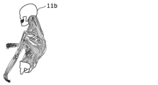
- the estimated rigid body link model 11a By applying the estimated rigid body link model 11a to the musculoskeletal model 11b as shown in FIG.
- the amount of load applied to at least one of the muscles and joints of each body part is calculated as an estimated value. Since the estimated value of the load on at least one of the muscles and joints of each body part is accumulated as the duration of the stationary posture increases, calculation using the estimated value of the load and the duration The degree of fatigue due to the object person 11 maintaining a still posture is calculated by .
- “at least one of muscles and joints” is also expressed as “muscles and/or joints.”
- the degree of fatigue based on the estimated value of the blood flow of the subject 11 in addition to the estimated value of the load applied to the muscles and/or joints.
- an example of estimating the fatigue level of the subject 11 using the estimated values of the load on the muscles and the load on the joints will be mainly described. It is also possible to estimate the degree of fatigue of the subject 11 with higher accuracy.
- the fatigue level of the subject 11 can also be estimated using an estimated value of any one of the amount of load on the muscles of the subject 11, the amount of load on the joints, and the amount of blood flow.
- the fatigue estimation system 200 estimates at least one of the amount of load on the muscles of the subject 11, the amount of load on the joints, and the amount of blood flow based on the duration of the posture. to estimate The fatigue estimation system 200 estimates the degree of fatigue of the subject 11 based on the estimated value of at least one of the estimated muscle load, joint load, and blood flow of the subject 11 .
- the estimated value of the load amount may be simply referred to as the load amount or the estimated value.
- the load is replaced with the blood flow, a large load is replaced with a decrease in blood flow, and a small load is replaced with an increase in blood flow.
- the blood flow is information for quantifying the blood flow that deteriorates when the subject 11 maintains the posture.
- the blood flow may be obtained as an absolute numerical value at the time of measurement, or may be obtained as a relative numerical value between two different time points.
- the degree of deterioration of the blood flow of the subject 11 can be estimated from the posture of the subject 11 and the relative numerical values of the blood flow at two points of time when the posture starts and ends.
- the blood flow rate of the subject can be calculated simply from the posture of the subject 11 and the duration of the posture. can be estimated.
- the musculoskeletal model 11b is used to estimate at least one of the load on the muscles, the load on the joints, and the blood flow from the posture of the subject 11. Therefore, in addition to the musculoskeletal model 11b described above, it is also possible to apply a method using actual measurement data as a method of estimating the amount of load on muscles, the amount of load on joints, and the amount of blood flow.
- This measured data is a database constructed by accumulating measured values of load on muscles, load on joints, and blood flow, which are measured for each posture, in association with the posture.
- the fatigue estimation system 200 in this case, by inputting the estimated posture of the subject 11 into the database, the measured values of the load on the muscles, the load on the joints, and the blood flow in the corresponding posture are calculated. can be obtained as output.
- the actual measurement data may be constructed using actual measurement values for each individual in consideration of individual differences in the subject 11, and statistical analysis or machine learning is performed for big data obtained from an unspecified number of subjects. It may be qualified and constructed so as to match each subject 11 by analysis processing such as.
- FIG. 2 is a block diagram showing the functional configuration of the fatigue estimation system according to the embodiment.
- the fatigue estimation system 200 in the present disclosure includes an estimation device 100, an imaging device 201, a timing device 202, a pressure sensor 203, a reception device 204, a storage device 215, a height sensor 216, a display device 205, and A recovery device 206 is provided.
- Estimation apparatus 100 includes a first acquisition unit 101, a second acquisition unit 102, a third acquisition unit 103, a fourth acquisition unit 104, a fifth acquisition unit 115, a sixth acquisition unit 116, and a posture estimation unit. 105 , a first calculation unit 106 , a second calculation unit 107 , a fatigue estimation unit 108 and an output unit 109 .
- the first acquisition unit 101 is a communication module that is connected to the imaging device 201 and acquires an image of the subject 11 from the imaging device 201 . That is, the first acquisition unit 101 is an example of an acquisition unit.
- the first acquisition unit 101 also has a function of detecting fixtures (for example, the chair 12 and the desk 13) included in the acquired image and detecting the top surface of the fixtures. That is, the first acquisition unit 101 is also an example of a detection unit that detects the top surface of furniture included in the image.
- the connection between the first acquisition unit 101 and the imaging device 201 is performed by wire or wirelessly, and the method of communication performed through the connection is not particularly limited.
- the second acquisition unit 102 is a communication module that is connected to the clock device 202 and acquires time from the clock device 202 .
- the connection between the second acquisition unit 102 and the timing device 202 is performed by wire or wirelessly, and the method of communication performed through the connection is not particularly limited.
- the third acquisition unit 103 is a communication module that is connected to the pressure sensor 203 and acquires pressure distribution from the pressure sensor 203 .
- the connection between the third acquisition unit 103 and the pressure sensor 203 is performed by wire or wirelessly, and the method of communication performed through the connection is not particularly limited.
- the fourth acquisition unit 104 is a communication module that is connected to the reception device 204 and acquires personal information from the reception device 204 .
- the connection between the fourth acquisition unit 104 and the reception device 204 is performed by wire or wirelessly, and the method of communication performed through the connection is not particularly limited.
- the fifth acquisition unit 115 is a communication module that is connected to the storage device 215 and acquires the length L (see FIG. 3B) of the lumbar skeleton 11m (see FIG. 3A) of the subject 11. That is, the first acquisition unit 101 is an example of an acquisition unit.
- the fifth acquisition unit 115 is an example of a length acquisition unit that acquires the length of the lumbar skeleton 11m.
- the fifth acquisition unit 115 acquires the length L of the lumbar spine skeleton 11m of the subject 11 stored in advance in the storage device 215 by accessing the storage device 215 .
- the fifth acquisition unit 115 transmits information about the target person 11 (identification information for identifying the target person 11 from others) as a query to the storage device 215, and as a response result to the query, the target person 11 obtain the length L of the lumbar skeleton 11 m.
- the length of the lumbar skeleton is one of the joint-connecting skeletons that extends from the back joint 11l (see FIG. 3A) of the subject 11 and connects to the lumbar joint 11n (see FIG. 3A).
- the fifth acquisition unit 115 may or may not be used depending on the extent to which the invisible part 11c (see FIG. 3A) extends to the subject.
- the fifth acquisition depends on which part of the subject 11 the boundary between the unhidden visible part 11d (see FIG. 3A) of the subject 11 and the hidden invisible part 11c as seen from the imaging device 201 corresponds.
- Part 115 may not be necessary.
- the fifth acquisition unit 115 may not be provided. That is, the fifth acquisition unit 115 is not an essential component.
- the storage device 215 may also function as a storage device (not shown) described below.
- the fifth acquisition unit 115 acquires the height H2 (see FIG. 3B) from the seat surface to the waist joint 11n when the subject 11 is seated.
- the weight of the subject 11 and the thickness of the buttocks involved in sitting are involved in the height H2.
- the fifth acquisition unit 115 transmits information about the subject 11 as a query to the storage device 215, and acquires the height H2 of the subject 11 as a response to the query.
- connection between the fifth acquisition unit 115 and the storage device 215 is performed by wire or wirelessly, and there is no particular limitation on the method of communication performed via the connection.
- the sixth acquisition unit 116 is a communication module that is connected to the height sensor 216 and acquires the height H1 (see FIG. 3B) of the seat surface of the chair 12 on which the subject 11 sits.
- the height sensor 216 is attached to the chair 12 and detects and transmits the height H1 when the subject 11 is seated on the chair 12 .
- the sixth acquisition unit 116 receives the height H2 detected by the height sensor 216 .
- the height H2 matches the height of the waist joint 11n of the subject 11 by combining with the height H1. That is, it can be said that the fifth acquisition unit 115 and the sixth acquisition unit 116 receive the height H2 and the height H1, respectively, and acquire the height of the waist joint 11n. Therefore, it can be said that the fifth acquisition unit 115 and the sixth acquisition unit 116 together constitute an example of the height acquisition unit.
- the height acquisition unit may also be implemented by a processing unit or the like that acquires an image of the subject 11 sitting and calculates the height of the waist joint 11n of the subject 11 from the image.
- the image may be acquired by the imaging device 201, but depending on the positional relationship between the imaging device 201 and the subject 11, the waist joint 11n may not appear in the image.
- the subject 11 is guided in advance to move to a range that can be captured in the image, and is seated on the chair 12 within this range. You can also
- connection between the sixth acquisition unit 116 and the height sensor 216 is performed by wire or wirelessly, and there is no particular limitation on the method of communication performed through the connection.
- the posture estimation unit 105 is a processing unit realized by executing a predetermined program using a processor and memory.
- the posture of the subject 11 is estimated by the processing of the posture estimation unit 105 based on the image acquired by the first acquisition unit 101 and the pressure distribution acquired by the third acquisition unit 103 .
- the first calculation unit 106 is a processing unit realized by executing a predetermined program using a processor and memory. Based on the estimated posture of the subject 11 and the personal information acquired by the fourth acquisition unit, the amount of load applied to each muscle and/or joint is calculated by the processing of the first calculation unit 106 .
- the second calculation unit 107 is a processing unit realized by executing a predetermined program using a processor and memory. Through the processing of the second calculation unit 107, the amount of recovery from fatigue in each muscle and/or joint is calculated based on the estimated amount of change in the posture of the subject.
- the fatigue estimation unit 108 is a processing unit realized by executing a predetermined program using a processor and memory. Fatigue estimation section 108 uses the posture estimated by posture estimation section 105 and the time acquired by second acquisition section 102 to estimate the degree of fatigue of subject 11 based on the duration of the posture estimated. presume.
- the output unit 109 is a communication module that is connected to the display device 205 and the recovery device 206 and outputs the content based on the fatigue level estimation result by the estimation device 100 to the display device 205 and the recovery device 206 .
- the connection between the output unit 109 and the display device 205 or the recovery device 206 is performed by wire or wirelessly, and the method of communication performed through the connection is not particularly limited.
- the imaging device 201 is a device that captures an image of the subject 11 and outputs an image, and is realized by a camera.
- an existing camera such as a security camera or a fixed-point camera may be used in the space where the fatigue estimation system 200 is applied, or a dedicated camera may be newly provided.
- Such an imaging device 201 is an example of an information output device that outputs an image as information about the position of the body part of the subject 11 . Therefore, the information to be output is an image, and is information including the positional relationship of the body parts of the subject 11 projected on the imaging device.
- the clock device 202 is a device that measures time and is implemented by a clock.
- the clock device 202 can transmit time to the connected second acquisition unit 102 .
- the time measured by the timer 202 may be absolute time or relative elapsed time from a starting point.
- the timing device 202 can be realized in any form as long as it can measure the time between two points of time when the target person 11 is detected to be still and when the degree of fatigue is estimated (that is, the duration of the stationary posture). good.
- the pressure sensor 203 is a sensor having a detection surface, and measures the pressure applied to each of the unit detection surfaces that divide the detection surface into one or more. The pressure sensor 203 thus measures the pressure for each unit detection surface and outputs the pressure distribution on the detection surface. The pressure sensor 203 is provided so that the subject 11 is positioned on the detection surface.
- the pressure sensors 203 are provided on the seat surface and the backrest of the chair on which the subject 11 sits. Further, for example, the pressure sensor 203 may have a marker attached on the detection surface, and the subject 11 may be guided onto the detection surface by a display such as "Please sit on the marker.” Further, by guiding the subject 11 onto the detection surface of the pressure sensor 203 provided on a part of the floor in this manner, the pressure sensor 203 may output the pressure distribution of the subject 11 on the floor. good. Since the pressure distribution is used for the purpose of improving the accuracy of estimating the degree of fatigue, the fatigue estimation system 200 may be implemented without the pressure sensor 203 if sufficient accuracy is ensured.
- the reception device 204 is a user interface that receives input of the personal information of the subject 11, and is realized by an input device such as a touch panel or keyboard.
- the personal information includes at least one of age, sex, height, weight, muscle mass, stress level, body fat percentage, and exercise proficiency.
- the age of the target person 11 may be a specific numerical value, or may be an age group divided by 10 years such as teens, 20s, and 30s.
- the age range may be divided into two divisions based on a predetermined age, such as age and older, or other age groups.
- the gender of the subject 11 is one suitable for the subject 11, which is selected from two of male and female.
- the height and weight numerical values of the height and weight of the target person 11 are respectively accepted.
- the muscle mass the muscle composition ratio of the subject 11 measured using a body composition meter or the like is accepted.
- the stress level of the subject 11 is selected by the subject 11 himself/herself from options such as high, medium, and low as the degree of subjective stress felt by the subject 11 .
- the body fat percentage of the subject 11 is the ratio of the body fat weight to the body weight of the subject 11, and is expressed, for example, as a percentage of 100.
- the subject's 11 exercise proficiency may be quantified by a score obtained when the subject 11 executes a predetermined exercise program, or may be the status of the exercise that the subject 11 usually engages in.
- the former is quantified by, for example, the time required to perform ten spins, the time required to run 50 meters, the flight distance of a long throw, and the like.
- the latter is quantified by, for example, how many days a week you exercise or how many hours you exercise. Since the personal information is used for the purpose of improving the accuracy of estimating the degree of fatigue, the fatigue estimation system 200 may be implemented without the reception device 204 if sufficient accuracy is ensured.
- the storage device 215 is a device capable of storing information, as described above.
- the storage device 215 is implemented by a semiconductor memory, an optical disk, a magnetic disk, or the like.
- the height sensor 216 is a sensor for detecting the height of the object, as described above.
- the height sensor 216 here is configured to detect the height of the seat surface of the chair 12 .
- the display device 205 is a device for displaying the content based on the fatigue level estimation results output by the output unit 109 .
- the display device 205 displays an image showing the content based on the result of estimating the degree of fatigue using a display panel such as a liquid crystal panel or an organic EL (Electro Luminescence) panel.
- a display panel such as a liquid crystal panel or an organic EL (Electro Luminescence) panel.
- the contents displayed by the display device 205 will be described later. Further, if the fatigue estimation system 200 is configured to only reduce the degree of fatigue of the subject 11 using the recovery device 206 for the subject 11, only the recovery device 206 may be provided, and the display device 205 Not required.
- the recovery device 206 is a device that reduces the degree of fatigue of the subject 11 by promoting the subject's 11 blood circulation. Specifically, the recovery device 206 changes the arrangement of each part of the chair 12 by applying voltage, pressurizing, vibrating, heating, or the like, or by a mechanism provided in the chair 12, so that the sitting subject 11 Actively change the posture of As a result, the recovery device 206 changes the load on at least one of the muscles and joints of the subject 11 and promotes blood circulation. From the viewpoint of the blood flow, by promoting the blood circulation in this way, the influence of the deterioration of the blood flow due to the subject 11 being in a still posture is reduced, and the degree of fatigue is recovered. The recovery device 206 is pre-applied or contacted to the appropriate body part of the subject 11, depending on the configuration of the device.
- the fatigue estimation system 200 is configured to display only the fatigue level estimation result to the subject 11, only the display device 205 is required, and the recovery device 206 is not essential.
- FIG. 3A is a first diagram illustrating posture estimation according to the embodiment.
- FIG. 3B is a second diagram illustrating posture estimation according to the embodiment.
- 3A and 3B show a subject 11 sitting on a chair 12 and working with a work target (not shown) placed on a desk 13 .
- 3A and 3B show plan views of the subject 11 from the lateral direction of the subject 11 (the direction orthogonal to the plane in which the subject 11, the chair 12, and the desk 13 are arranged).
- a part of the subject 11 may be positioned behind the desk 13 as viewed from the imaging device 201. Therefore, it is difficult to estimate the posture of such an invisible part 11c in the image captured by the image capture device 201 .
- the angle 11x formed by the lumbar skeleton 11m and the thigh skeleton 11o is an important part of determining the posture of the trunk portion.
- the thigh skeleton 11o is often included in the non-visible region, and many situations occur in which it is difficult to estimate the angle 11x.
- the thigh skeleton 11o is likely to form a predetermined angle with the horizontal plane according to a certain rule. It has been found that it is possible to estimate the extending direction of the femoral skeleton 11o from the end.
- the above-mentioned certain rule is, for example, when the subject 11 is in a sitting position, the extension direction of the femoral skeleton 11o is nearly parallel to the horizontal plane (the predetermined angle is 0 degrees), that is, the predetermined angle is ⁇
- the angle should be within the range of 10 degrees to 10 degrees.
- the certain rule is, for example, when the subject 11 is in a standing position, the direction in which the femoral skeleton 11o extends is nearly perpendicular to the horizontal plane (the predetermined angle is 90 degrees), that is, the predetermined angle is The angle should be within the range of 80 degrees to 100 degrees.
- the certain rule is, for example, when the subject 11 is lying down, the extending direction of the femoral skeleton 11o is nearly parallel to the horizontal plane (the predetermined angle is 0 degrees), that is, the predetermined angle is The angle should be within the range of -10 degrees to 10 degrees. It should be noted that the above-described angular range regarding the predetermined angle is an example, and a wider angular range may be applied according to the habit of posture of the subject 11 or the like. Moreover, there is no directivity in such a relative angular relationship, and the above 0 degrees is the same as 180 degrees. Similarly, 90 degrees above is the same as 270 degrees. That is, in this description, even if a multiple of 180 degrees is added to or subtracted from the predetermined angle, it is treated as the same as the predetermined angle.
- the thigh skeleton 11o is used as an example, but any skeleton that can determine a predetermined angle with respect to the horizontal plane according to a certain rule can also be used as the invisible part 11c.
- the posture estimation target here is not limited to the thigh skeleton 11o.
- the top surface of furniture such as the desk 13 is used to detect the horizontal plane.
- the rectangular top surface becomes a rectangle with right angles as it approaches the direction orthogonal to the imaging direction, and becomes a trapezoidal shape with a larger difference in length between the upper and lower bases as it approaches the direction parallel to the imaging direction.
- the fixtures used for detecting the horizontal plane may be fixtures around the target person 11 .
- fixtures other than the desk 13 may be used as long as the fixtures are included in the image together with the subject 11 .
- the upper surface of the storage can be detected as the top surface and used as a horizontal plane.
- the invisible part 11c includes the thigh skeleton 11o and the joints and skeletons on the toe side, as indicated by the dashed lines and white circles included in the rigid body link model 11a in the figure.
- the visible part 11d includes the waist joint 11n, and the joints and skeleton closer to the head than the waist joint 11n, as indicated by solid lines and black circles included in the rigid body link model 11a in the figure.
- the invisible part 11c includes the lumbar skeleton 11m, the lumbar joint 11n, the thigh skeleton 11o, and the joints and skeletons on the toe side.
- the visible part 11d includes the back joint 11l included in the rigid body link model 11a in the figure, and the joints and skeleton on the head side thereof.
- the posture of the invisible part 11c is estimated so that the thigh skeleton 11o extends from the estimated position of the waist joint 11n so as to be parallel to the horizontal plane (chain line) estimated from the desk surface 13a, , it is possible to easily estimate the angle 11x.
- the estimation of the posture of the invisible part 11c is performed only for some estimable parts. Other parts (knee joints, etc.) may be ignored or estimated by another method.
- FIG. 4A is a flowchart showing a fatigue level estimation method according to the embodiment. Also, FIG. 4B is a sub-flow chart showing details of some steps according to the embodiment.
- the fatigue estimation system 200 first acquires the personal information of the subject 11 (step S101). Acquisition of personal information is performed by the target person 11 himself/herself or an administrator or the like who manages the fatigue level of the target person 11 by inputting to the reception device 204 .
- the input personal information of the subject 11 is stored in a storage device or the like (not shown), and is read out and used when estimating the degree of fatigue.
- the fatigue estimation system 200 detects the subject 11 using the imaging device 201 (step S102). Detection of the subject 11 is performed by determining whether or not the subject 11 has entered the angle of view of the camera, which is the imaging device 201 .
- the target person 11 may be a specific target person 11, or may be a person from among an unspecified number of people who enters the angle of view of the camera. When the target person 11 is selected from an unspecified number of people, the input of personal information may be omitted. Further, when detecting a specific target person 11, a step of specifying the target person 11 by image recognition or the like is added.
- the target person 11 inputs personal information, grasps the detection area by the imaging device 201, and enters the detection area to estimate the fatigue level. Therefore, image recognition or the like is not required, and the degree of fatigue is estimated by adding personal information.
- step S102 When the fatigue estimation system 200 determines that the target person 11 has not been detected (No in step S102), it repeats step S102 until the target person 11 is detected.
- the image output by the imaging device 201 is acquired by the first acquisition unit 101 (step S103, an example of an acquisition step).
- the estimation device 100 estimates the posture of the subject 11.
- the posture estimation unit 105 estimates the posture of the subject 11 based on the acquired image and pressure distribution (posture estimation step S106).
- posture estimation step S106 is executed according to the sub-flowchart shown in FIG. 4B.
- the first acquisition unit 101 detects furniture (desk 13 in this case) in the acquired image, and detects its top surface (desk top surface 13a) (step S106a). This allows estimation of the direction parallel to the horizontal plane within the image.
- the posture estimation unit 105 estimates the posture of the visible part 11d based on the subject included in the image (step S106b). As a result, the positions of joints and skeletons included in the visible part 11d are estimated.
- the posture estimation unit 105 estimates the posture of the invisible part 11c based on the detected top surface (step S106c). Here, for example, the position of the thigh skeleton 11o is estimated. Then, the posture estimation unit 105 corrects the estimated posture (postures of the visible part 11d and the invisible part 11c) based on the pressure distribution acquired by the third acquisition unit 103 (step S106d).
- Posture correction based on pressure distribution is performed, for example, as follows.
- the pressure distribution is used, for example, when biased pressure is applied, to correct the estimated pose to form that bias.
- the first calculator 106 calculates the amount of load on each muscle and/or joint of the subject 11 from the posture estimation result.
- the personal information obtained in advance is used to correct and calculate the load amount (step S107).
- the estimation of the posture of the subject 11 is as described with reference to FIG. 1B, and the calculation of the amount of load is as described with reference to FIG. 1C, so detailed description thereof will be omitted.
- peak values may be based on the subject's 11 gender. Also, if the sex of the subject 11 is male, the amount of load may be small, and if the sex of the subject 11 is female, the amount of load may be large. Alternatively, the smaller the height and weight of the subject 11, the smaller the load, and the larger the height and weight, the larger the load.
- the load amount may be reduced as the composition ratio of the subject 11 has a large muscle mass, and the load amount may be increased as the composition ratio of the muscle mass of the subject 11 is small.
- the duration of the stationary posture of the subject 11 is measured based on the time acquired by the second acquisition unit 102 (step S108).
- the fatigue estimating unit 108 adds the load amount calculated above each time the duration time passes by the unit time, and estimates the degree of fatigue of the subject 11 at this point (fatigue estimation step S109).
- the processes of step S108 and fatigue estimation step S109 are continued until the target person 11 is released from the stationary state. Specifically, it is determined whether or not the stationary state has been released, depending on whether or not the orientation estimated by the orientation estimation unit 105 has changed from a static orientation (step S110).
- step S110 If it is not determined that the stationary state has been released (No in step S110), the process returns to step S108, measures the duration, proceeds to fatigue estimation step S109, adds the load amount, and continues as long as the stationary posture continues.
- the degree of fatigue of the subject 11 is accumulated. That is, the fatigue estimating unit 108 repeats step S108 and fatigue estimating step S109 to estimate the fatigue level of the subject 11 using a fatigue degree increasing function having a slope corresponding to the calculated load amount with respect to the duration time. Estimate degrees. Therefore, the greater the calculated load amount, the greater the degree of fatigue of the subject 11 that increases per unit time.
- the fatigue level of the subject 11 is initialized (set to 0) at the start timing of the stationary posture, which is the starting point.
- the posture estimation unit 105 calculates the amount of change in posture from the original stationary state posture to the current posture.
- the amount of change in posture is calculated for each individual muscle and/or joint, similar to the amount of load described above.
- the second calculation unit 107 calculates the amount of recovery, which is the degree of recovery from fatigue, based on the amount of change in posture (step S111).
- the change time which is the time during which the posture of the subject 11 continues to change, is measured (step S112).
- the relationship between the recovery amount and the change time is the same as the relationship between the load amount and the duration time, and the recovery amount of the subject 11 is integrated as long as the posture change continues. That is, the fatigue estimating unit 108 estimates the fatigue level of the subject 11 by subtracting the recovery amount each time the unit time elapses at the timing when the posture of the subject 11 changes (step S113).
- steps S111, S112, and S113 are continued until the posture of the subject 11 is stationary. Specifically, whether or not the posture estimated by the posture estimation unit 105 is a static posture is determined based on whether or not the subject 11 is detected to be still (step S114). If the subject 11 is not detected still (No in step S114), return to step S111 to calculate the amount of recovery, proceed to step S112 to measure the change time, and proceed to step S113 to subtract the amount of recovery. Then, as long as the posture change is continued, the fatigue level of the target person 11 is accumulated so as to recover.
- the fatigue estimating unit 108 repeats steps S111, S112, and S113, and uses a decreasing function of the degree of fatigue having a slope corresponding to the calculated recovery amount with respect to the change time.
- Estimate fatigue Since the recovery amount of the fatigue level depends on the amount of change in posture, the greater the amount of change in posture, the greater the fatigue level of the subject 11, which decreases per unit time.
- step S114 if the subject 11 is detected to be stationary (Yes in step S114), the process returns to step S105, and the posture and fatigue level are estimated again for a new stationary posture.
- the fatigue estimation system 200 since the fatigue level of the subject 11 is calculated in consideration of the duration time in the stationary posture based on the image, the burden on the subject 11 is small, and more accurate The degree of fatigue of the subject 11 can be estimated.
- FIG. 5A is a diagram showing a subject standing still in Posture A.
- FIG. 5B is a diagram showing the subject standing still in the posture B. As shown in FIG.
- the subject 11 shown in FIGS. 5A and 5B is in a stationary posture in a seated position on a chair 12, similar to that shown in FIG. 1A.
- FIGS. 5A and 5B there are actually tables, PCs, etc., which are not shown, but only the subject 11 and the chair 12 are shown here.
- the stationary posture of the subject 11 shown in FIG. 5A is posture A in which the load on the shoulders is relatively large.
- the stationary posture of the subject 11 shown in FIG. 5B is posture B in which the load on the shoulder is relatively small.
- FIG. 6A is a first diagram illustrating accumulation of estimated fatigue level of a subject according to the embodiment.
- FIG. 6B is a second diagram illustrating accumulation of the subject's fatigue level estimated according to the embodiment.
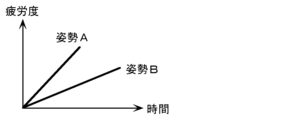
- posture A is a posture with a larger load than posture B. Therefore, for example, in certain muscles of the subject 11 (here, muscles related to shoulder movement), the load amount of posture A (slope of the straight line of posture A) is greater than the load of posture B (slope of the straight line of posture B). is also big. Therefore, in the posture A, the target person 11 accumulates (accumulates) a larger degree of fatigue in a shorter time than in the case of standing still in the posture B.
- the degree of fatigue of the subject 11 is an increasing function with a positive slope corresponding to the load amount in the posture A, as in FIG. is estimated as the accumulation (addition) of the degree of fatigue by , and the accumulation (addition) turns to recovery (decrease) at the change point where the subject 11 begins to change the posture.
- the degree of fatigue of the subject 11 is determined by a decreasing function with a negative slope corresponding to the amount of change in posture. It recovers (decreases) by the amount shown as the change width inside.
- the fatigue level of the subject 11 is an increasing function with a positive slope corresponding to the load amount of the posture B, and is estimated as accumulation (addition) of the fatigue level. be done.
- the degree of fatigue of the subject 11 is estimated in which accumulation and recovery are reflected according to the rest and change of the posture of the subject 11 .
- FIG. 7 is a first diagram showing a display example of estimation results according to the embodiment.
- FIG. 8 is a second diagram showing a display example of estimation results according to the embodiment.
- the result of estimating the degree of fatigue of the subject 11 can be displayed using the display device 205 and fed back.
- a display device 205 integrally displays a doll simulating the subject 11 and fatigue levels of the subject 11's shoulders, back, and main parts.
- the fatigue level of the shoulder is indicated as "stiff shoulder”
- the fatigue of the back is indicated as “back pain”
- the fatigue of the lower back is indicated as "low back pain”.
- the fatigue levels of the subject 11 at three locations are displayed at once, and the fatigue levels at these three locations are estimated from images captured at once. That is, the estimating apparatus 100 detects muscles and/or joints in each of a plurality of body parts including a first part (eg, shoulder), a second part (eg, back), and a third part (eg, waist) of the subject 11. , the degree of fatigue is estimated from one posture of the subject 11 . Therefore, even if the posture of the subject 11 is constant, the degree of fatigue accumulated in muscles and/or joints differs for each body part. can be estimated.
- a first part eg, shoulder
- a second part eg, back
- a third part eg, waist
- the load amount is calculated for each muscle and/or joint of the subject 11. Therefore, if there is no processing resource limitation, each muscle and/or joint fatigue can be estimated. Therefore, there is no limit to the number of body parts whose fatigue levels are estimated from images captured at one time, and the number may be one, two, or four or more.
- the estimating device 100 calculates the load amount for each of a plurality of body parts, and calculates the degree of fatigue (the degree of stiff shoulders) of the first part based on the load amount calculated for the first part in one posture of the subject 11. , the fatigue level of the second part (the above-mentioned back pain level) due to the load amount calculated at the second part, and the fatigue level of the third part (the above-mentioned low back pain level) due to the load amount calculated at the third part, can be estimated.
- the degree of stiff shoulders is estimated from the amount of load on the trapezius muscle
- the degree of back pain is estimated from the degree of fatigue of the latissimus dorsi muscle
- the degree of low back pain is estimated from the amount of load on the lumbar paraspinal muscles.
- one fatigue level may be estimated from the load of one muscle and / or joint, but one fatigue level is estimated from the combined load of a plurality of muscles and / or joints.
- the degree of stiff neck that is, one degree of shoulder fatigue
- the degree of stiff neck may be estimated from the average value of the loads of the trapezius muscle, the levator scapula muscle, the rhomboid muscle, and the deltoid muscle.
- a more realistic fatigue degree can be estimated by weighting the amount of load on muscles and/or joints that have a particularly large effect on the degree of fatigue of the relevant body part, instead of using a simple average value. Estimates may be made.
- the degree of fatigue estimated in this way may be indicated as a relative position on a reference meter with a minimum value of 0 and a maximum value of 100 as shown.
- a reference value is provided at a predetermined position on the reference meter.
- Such a reference value is set to the relative position (or before and after) of the degree of fatigue at which subjective symptoms such as pain may occur in a general subject 11 quantified in advance by an epidemiological survey or the like. Therefore, different reference values may be set according to the degree of fatigue of each body part.
- the display device 205 may display a warning to the target person 11 as an estimation result when the estimated fatigue level of the target person 11 reaches the reference value.
- the reference value here is an example of the first threshold.
- the display device 205 may display a specific coping method such as "Recommend taking a break" as shown in the drawing.
- the display device 205 displays the currently estimated fatigue level of the target person 11 for the target person 11 when the estimated fatigue level of the target person 11 reaches the reference value.
- a recommended posture with less load on the body part that reaches the reference value may be displayed.
- the reference value here is an example of the second threshold, and may be the same as or different from the first threshold.
- the displayed recommended posture may be accompanied by specific notes such as "put your weight on the back of the chair” and "sit deeply on the seat” together with the doll that assumes that posture.
- the fatigue estimation system 200 actively activates the subject 11. It is also possible to consider a configuration that recovers the degree of fatigue of the user. Specifically, the recovery device 206 shown in FIG. 2 operates to recover the degree of fatigue of the subject 11 .
- the specific configuration of the recovery device 206 is as described above, so a description thereof will be omitted.
- the reference value here is an example of the third threshold, and may be the same as or different from either the first threshold or the second threshold.
- the fatigue estimation system 200 in the first aspect of the present embodiment is a fatigue estimation system 200 that estimates the fatigue level of the subject 11 whose part is hidden when viewed from the imaging device 201,
- An imaging device 201 that captures an image including the target person 11 and fixtures (desk 13, etc.) around the target person 11;
- a detection unit (for example, included in the first acquisition unit 101 as one of the functions) that detects the top surface of fixtures (such as the desk surface 13a) included in the acquired image, and a posture that estimates the posture of the subject 11
- the estimating unit 105 estimates the posture of the visible part 11d of the target person 11 that is not hidden when viewed from the imaging device 201 based on the target person 11 included in the image, and based on the detected top surface , a posture estimation unit 105 that estimates the posture of the invisible part 11c of the target person 11 that is hidden when viewed from the imaging device 201, and the fatigue level of the target person 11 is estimated based on the estimated posture of the target person 11. and
- Such a fatigue estimation system 200 can estimate the orientation of the invisible part 11c based on the top surface of the furniture. Therefore, the fatigue level of the subject 11 can be estimated based on the estimated posture of the invisible part 11c, compared to the case where the invisible part 11c exists and the fatigue level related to the invisible part is not estimated. Therefore, the degree of fatigue can be estimated with higher accuracy.
- the visible part 11d includes the waist joint 11n of the subject 11, and the invisible part 11c is the thigh of the subject 11, which is a skeleton extending from the waist joint 11n.
- the posture estimating unit 105 which includes the skeleton 11o, determines the extension direction of the thigh skeleton 11o extending in a direction forming a predetermined angle with respect to the top surface from the position of the waist joint 11n included in the estimated posture of the visible part 11d.
- the fatigue estimation system according to the first aspect, which estimates the
- the estimated thigh Since the fatigue level of the subject 11 can be estimated based on the posture of the partial skeleton 11o, the fatigue level can be estimated with higher accuracy.
- the visible part 11d includes the back joint 11l of the subject 11, and the invisible part 11c is the lumbar skeleton 11m of the subject 11, which is a skeleton extending from the back joint 11l.
- the fatigue estimation system 200 further includes a lumbar joint 11n of the subject 11 connected to the back joint 11l via and a thigh skeleton 11o of the subject 11, which is a skeleton extending from the lumbar joint 11n.
- a fifth acquisition unit 115 (hereafter, length acquisition unit) that acquires the length
- a fifth acquisition unit 115 and a sixth acquisition unit 116 (hereafter, height acquisition unit) that acquire the height of the waist joint 11n.
- the posture estimation unit 105 determines that the position of the back joint 11l included in the estimated posture of the visible part 11d is within the range of the length of the acquired lumbar spine skeleton 11m and matches the height of the acquired waist joint 11n.
- the position of the waist joint 11n is estimated, and the extension direction of the thigh skeleton 11o extending in a direction forming a predetermined angle with respect to the top surface is estimated from the estimated position of the waist joint 11n. It is a fatigue estimation system.
- the visible part 11d includes the back joint 11l of the subject 11, and the non-visible part 11c is connected to the back joint 11l via the lumbar skeleton 11m of the subject 11, which is a skeleton extending from the back joint 11l.
- the waist joint 11n of the person 11 and the thigh skeleton 11o of the subject 11, which is a skeleton extending from the waist joint 11n are included, the estimated posture of the waist joint 11n and the thigh skeleton 11o is used to determine the posture of the subject 11. can be estimated, the fatigue level can be estimated with higher accuracy.
- the predetermined angle is an angle within the range of 80 degrees to 100 degrees. It is a fatigue estimation system.
- the fifth aspect of the present embodiment is the fatigue estimation system according to the fourth aspect, in which the predetermined angle is 90 degrees when the subject 11 is standing.
- the predetermined angle is an angle within the range of -10 degrees to 10 degrees, either of the second or third aspect A fatigue estimation system according to one aspect.
- the seventh aspect of the present embodiment is the fatigue estimation system according to the sixth aspect, in which the predetermined angle is 0 degrees when the subject 11 is in a sitting position.
- the fixture is the desk 13 used by the subject 11, and the top surface is the desk surface 13a of the desk 13, any one of the first to seventh aspects.
- a fatigue estimation system according to one aspect.
- the posture of the invisible part 11c can be estimated using the desk surface 13a as the top surface of the desk 13 as furniture.
- the invisible part 11c is hidden by furniture when viewed from the imaging device 201.
- the fatigue estimation system according to any one aspect of the first to eighth aspects, be.
- the posture of the invisible part 11c of the target person 11 hidden behind the furniture can be estimated using the top surface of the fixture.
- an information output device for example, an imaging device 201 that outputs information about the position of the body part of the subject 11, and information (for example, an image) output by the information output device.
- An estimation device 100 that estimates the posture and estimates the degree of fatigue of the subject 11 based on the estimated posture and the duration of the posture.
- the information output device is the imaging device 201 that captures an image of the subject 11 and outputs an image as information about the position of the body part, and the estimation device 100 outputs the image based on the image output by the imaging device 201.
- the posture of the subject 11 may be estimated.
- Such a fatigue estimation system 200 can estimate the degree of fatigue of the subject 11 using the image output by the imaging device 201 .
- the posture of the subject 11 estimated from the output image is used. Specifically, the amount of load on the muscles, the amount of load on the joints, and the deterioration of blood flow due to the maintenance of a certain static posture are calculated from the duration of time spent in the static posture in which the posture of the subject 11 is still. Accumulation of fatigue accompanying such as is quantified as a degree of fatigue.
- the degree of fatigue of the subject 11 is calculated based on the image, taking into account the duration of the stationary posture, so that the burden on the subject 11 is reduced, and more accurate It is possible to estimate the degree of fatigue of the subject 11 in a static posture.
- the estimating apparatus 100 calculates the amount of load on at least one of the muscles and joints of the subject 11 used to maintain the estimated posture using the musculoskeletal model 11b, and increases the degree of fatigue with respect to the duration.
- the fatigue level may be estimated using a function, and in the increasing function used for estimating the fatigue level, the greater the calculated load amount, the greater the fatigue level that increases per unit time.
- the load amount for at least one of individual muscles and joints is calculated using the musculoskeletal model 11b.
- the degree of fatigue of the subject 11 can be easily estimated by an increasing function whose slope is the amount of load calculated in this manner. Therefore, it is possible to easily estimate the degree of fatigue of the subject 11 with higher accuracy.
- the estimating apparatus 100 calculates the load amount of at least one of muscles and joints in each of two or more body parts including the first part and the second part among the body parts of the subject 11, In one posture of 11, at least a first fatigue level of the first part based on the load amount calculated for the first part and a second fatigue level of the second part based on the load amount calculated for the second part are calculated. can be estimated.
- the degree of fatigue for two or more body parts of the subject 11 with one imaging. There is no need to perform measurements for estimating fatigue levels for each body part, and the fatigue levels of a plurality of body parts can be estimated quickly and substantially simultaneously.
- the degree of fatigue estimated substantially at the same time makes it possible to easily specify the body part of the subject 11 that is likely to get fatigued, which is effective when devising a coping method for recovering from the degree of fatigue. Therefore, it is possible to quickly and effectively estimate the degree of fatigue of the subject 11 .
- the estimation apparatus 100 estimates the fatigue level using a decreasing function of the fatigue level with respect to time, and the decreasing function used for estimating the fatigue level has a large amount of change in posture.
- the degree of fatigue that decreases per unit time may be increased as much as possible.
- the load on at least one of the muscles and joints is changed, and the recovery of the fatigue level by improving the blood flow is reflected in the estimated fatigue level. be done. Therefore, it is possible to more accurately estimate the degree of fatigue of the target person 11 in relation to the position of the body part of the target person 11 in the still posture.
- the fatigue estimation system 200 further includes a display device that displays a warning to the target person 11 as an estimation result when the fatigue level of the target person 11 estimated by the estimation device 100 reaches the first threshold. 205 may be provided.
- the target person 11 and the like can know from the warning displayed on the display device 205 that the fatigue level of the target person 11 has reached the first threshold.
- the target person 11 can reduce the possibility of suffering from poor physical condition, injury, accident, etc. due to fatigue by coping with the accumulated fatigue level according to the displayed warning. Therefore, the degree of fatigue estimated with higher accuracy is used to suppress the discomfort caused by the fatigue of the subject 11 .
- the fatigue estimation system 200 may be triggered by the fact that the degree of fatigue of the subject 11 estimated by the estimation device 100 has reached the second threshold, and the load on the subject 11 may be more than the posture.
- a display device 205 that displays a few recommended postures may be provided.
- the target person 11 and the like can cope with the fatigue level of the target person 11 that has reached the second threshold by using the recommended posture displayed on the display device 205 .
- the recommended posture By changing to the recommended posture, it is expected that the degree of fatigue of the subject 11 will recover, so that the subject 11 can suppress accumulation of fatigue without being particularly conscious of it. Therefore, the degree of fatigue estimated with higher accuracy is used to suppress the discomfort caused by the fatigue of the subject 11 .
- the fatigue estimation system 200 further accelerates the blood circulation of the subject 11 when the fatigue level of the subject 11 estimated by the estimation device 100 reaches the third threshold.
- a recovery device 206 may be provided to reduce the degree of fatigue of the.
- the recovery device 206 since the recovery device 206 is expected to recover the degree of fatigue of the subject 11, the subject 11 can suppress the accumulation of fatigue without being particularly conscious of it. Therefore, the degree of fatigue estimated with higher accuracy is used to suppress the discomfort caused by the fatigue of the subject 11 .
- the fatigue estimation system 200 further includes a pressure sensor 203 that outputs a pressure distribution indicating the distribution of pressure applied on the detection surface, and the estimation device 100 detects the pressure distribution output by the pressure sensor 203. Based on this, the estimated posture of the subject 11 may be corrected, and the load amount for maintaining the corrected posture may be calculated.
- the pressure distribution output by the pressure sensor 203 can be used to estimate the posture of the subject 11 . Therefore, the posture of the subject 11 can be estimated with high accuracy by correcting the pressure distribution. Therefore, the degree of fatigue of the subject 11 can be estimated with higher accuracy.
- the fatigue estimation system 200 further includes personal information including at least one of age, sex, height, weight, muscle mass, stress level, body fat percentage, and exercise proficiency level of the subject 11. Equipped with a receiving device 204 that receives input, the estimating device 100 may correct the load amount based on the personal information received by the receiving device 204 when calculating the load amount for maintaining the estimated posture. good.
- the personal information received by the receiving device 204 can be used to calculate the amount of load. Therefore, the load amount in the stationary posture can be calculated with high accuracy by correction using the personal information. Therefore, the degree of fatigue of the subject 11 can be estimated with higher accuracy.
- the estimation device 100 is an estimation device 100 that estimates the fatigue level of the target person 11 whose part is hidden when viewed from the imaging device 201.
- a first acquisition unit 101 (hereinafter referred to as an image acquisition unit) that acquires an image including fixtures (desk 13, etc.) around the person 11 and the target person 11; etc.) (for example, included in the first acquisition unit 101 as one of the functions), and a posture estimation unit 105 for estimating the posture of the subject 11, which is included in the image. Based on this, the posture of the visible part 11d of the subject 11 that is not hidden when viewed from the imaging device 201 is estimated, and based on the detected top surface, the hidden subject 11 when viewed from the imaging device 201 is estimated. and a posture estimating unit 108 for estimating the subject's degree of fatigue based on the estimated subject's posture.
- Such an estimating device 100 can achieve the same effects as the fatigue estimating system 200 described above in combination with the imaging device 201 .
- a first acquisition unit 101 that acquires information about the positions of body parts of the subject 11, and a posture estimation unit 105 that estimates the posture of the subject 11 based on the information acquired by the first acquisition unit 101. and a fatigue estimation unit 108 that estimates the degree of fatigue based on the duration of the posture estimated by the posture estimation unit 105 .
- Such an estimation device 100 can estimate the degree of fatigue of the subject 11 using information such as acquired images.
- the posture of the subject 11 estimated from the acquired image or the like is used. Specifically, the load on at least one of the muscles and joints and the deterioration of blood flow due to the maintenance of a constant static posture from the duration of time elapsed in the static posture in which the posture of the subject 11 is static. The accumulation of fatigue associated with this is quantified as the degree of fatigue. In this way, since the estimation device 100 calculates the fatigue level of the subject 11 in consideration of the duration of the static posture, it is possible to more accurately estimate the fatigue level of the subject 11 in the static posture. can.
- the fatigue estimation method in the eleventh aspect of the present embodiment is a fatigue estimation method for estimating the degree of fatigue of the target person 11 whose part is hidden when viewed from the imaging device 201.
- An image including fixtures (desk 13, etc.) around the person 11 and the subject 11 is acquired, the top surface of the fixture (desk top 13a, etc.) included in the acquired image is detected, and the subject 11 included in the image is detected.
- the posture of the invisible part 11 c of 11 is estimated, and the degree of fatigue of the subject 11 is estimated based on the estimated posture of the subject 11 .
- Such a fatigue estimation method can achieve the same effects as the fatigue estimation system 200 described above.
- an acquisition step (step S103 or the like) of acquiring information about the positions of body parts of the subject 11, and a posture estimation step S106 of estimating the posture of the subject 11 based on the information acquired in the acquisition step. and a fatigue estimation step S109 for estimating the degree of fatigue based on the duration of the posture estimated in the posture estimation step S106.
- Such a fatigue estimation method has the same effects as the estimation device 100 described above.
- the processing executed by a specific processing unit may be executed by another processing unit.
- the order of multiple processes may be changed, and multiple processes may be executed in parallel.
- the fatigue estimation system or estimation device in the present disclosure may be realized by a plurality of devices each having a part of a plurality of components, or may be realized by a single device having all of the plurality of components. good. Also, some of the functions of a component may be implemented as functions of another component, and each function may be distributed among the components in any way.
- the present disclosure includes any form having a configuration in which substantially all of the functions that can realize the fatigue estimation system or the estimating device of the present disclosure are provided.
- each component may be realized by executing a software program suitable for each component.
- Each component may be realized by reading and executing a software program recorded in a recording medium such as a hard disk or a semiconductor memory by a program execution unit such as a CPU or processor.
- each component may be realized by hardware.
- each component may be a circuit (or integrated circuit). These circuits may form one circuit as a whole, or may be separate circuits. These circuits may be general-purpose circuits or dedicated circuits.
- the posture of the subject is estimated from the image using the rigid link model generated by image recognition, the load amount is calculated from the estimated posture of the subject, and based on the load amount and the duration time.
- the method of estimating the degree of fatigue is not limited to this. Any existing method may be used as a method of estimating the posture of the subject from the image, and any existing method may be used as a method of estimating the amount of load from the posture of the subject.
- FIG. 9 is a diagram explaining posture estimation according to a modification of the embodiment.
- the posture of the subject 11 is estimated using a sensor module 207 including a position sensor 207a and an electric potential sensor 207b.
- a plurality of sensor modules 207 are attached to the subject 11 here, but the number of sensor modules 207 attached to the subject 11 is not particularly limited. Only one sensor module 207 may be attached to the subject 11 .
- the mounting style of the sensor module 207 is not particularly limited, and any style may be used as long as the position of a predetermined body part of the subject 11 can be measured.
- the subject 11 is equipped with a plurality of sensor modules 207 by wearing a costume to which a plurality of sensor modules 207 are attached.
- the sensor module 207 is a device that is attached to a predetermined body part of the subject 11 and outputs information indicating the result of detection or measurement in conjunction with the predetermined body part. Specifically, the sensor module 207 outputs the position sensor 207a that outputs the position information regarding the spatial position of the predetermined body part of the subject 11, and the potential information that indicates the potential at the predetermined body part of the subject 11. It has a potential sensor 207b. Although the figure shows the sensor module 207 having both the position sensor 207a and the potential sensor 207b, the potential sensor 207b is not essential if the sensor module 207 has the position sensor 207a.
- the position sensor 207a in such a sensor module 207 is an example of an information output device that outputs position information as information relating to the position of the body part of the subject 11. Therefore, the information to be output is positional information, and is information including relative or absolute positions of predetermined body parts of the subject 11 . Also, the information to be output may include, for example, potential information.
- the potential information is information including the value of potential measured at a predetermined body part of the subject 11 . Position information and potential information will be described in detail below together with the position sensor 207a and the potential sensor 207b.
- the position sensor 207a detects a spatial relative position or an absolute position of a predetermined body part of the subject 11 to which the sensor module 207 is attached, and outputs information on the spatial position of the predetermined body part as a detection result. It is a vessel.
- the information about the spatial position includes information that can identify the position of the body part in the space as described above and information that can identify the change in the position of the body part due to body movement.
- the information about the spatial position includes information indicating the positions of the joints and the skeleton in space and changes in the positions.
- the position sensor 207a is configured by combining various sensors such as an acceleration sensor, an angular velocity sensor, a geomagnetic sensor, and a range sensor. Since the position information output by the position sensor 207a can approximate the spatial position of a predetermined body part of the subject 11, the posture of the subject 11 can be estimated from the spatial position of the predetermined body part.
- the electric potential sensor 207b is a detector that measures the electric potential at a predetermined body part of the subject 11 to which the sensor module 207 is worn and outputs information indicating the electric potential of the predetermined body part, which is the measurement result.
- the potential sensor 207b is a measuring instrument that has a plurality of electrodes and measures a potential generated between the plurality of electrodes using an electrometer.
- the potential information output by the potential sensor indicates the potential generated at a predetermined body part of the subject 11, and since the potential corresponds to the action potential of the muscle at the predetermined body part, the activity of the predetermined body part is detected. It is possible to improve the estimation accuracy of the posture of the subject 11 estimated from the potential or the like.
- the fatigue estimation system in this modified example estimates the degree of fatigue of the subject 11 using the posture of the subject 11 estimated as described above. It should be noted that the processing after estimating the posture of the subject 11 is the same as in the above-described embodiment, and thus the description thereof is omitted.
- the information output device is attached to a predetermined body part of the subject 11, and outputs position information about the spatial position of the predetermined body part as information about the position of the body part of the subject 11.
- the position sensor 207a outputs, and the estimation apparatus 100 estimates the posture of the subject 11 based on the position information output from the position sensor 207a.
- the fatigue level of the subject 11 can be estimated using the position information output by the position sensor 207a.
- the posture of the subject 11 estimated from the output information is used.
- the accumulation of fatigue caused by maintaining a constant static posture is quantified as the degree of fatigue based on the duration of time elapsed in the static posture in which the posture of the subject 11 is static.
- the degree of fatigue of the subject 11 is calculated in consideration of the duration of the stationary posture. It is possible to estimate the degree of fatigue of the subject 11 in a stationary posture with less burden and with higher accuracy.
- the increasing function and decreasing function are described as linear functions, but the present invention is not limited to this.
- the increasing function may be a curvilinear function as long as the fatigue level increases with time.
- the decreasing function may be a curvilinear function as long as it is a function that decreases the degree of fatigue over time.
- the estimation device described above uses the load on muscles, the load on joints, and the blood flow estimated from the posture of the subject to estimate the degree of fatigue of the subject. As described above, it is also possible to correct the estimated value using the value measured using the measuring device to achieve more accurate estimation of the degree of fatigue. Specifically, the estimating device acquires a measured value corresponding to the estimated value, which is a measured value based on the measurement result of measuring the subject by the measuring device.
- the detection device is, for example, an electromyograph, a muscle hardness meter, a pressure gauge, a near-infrared spectrometer, etc., and obtains measured values regarding the amount of load on muscles, the amount of load on joints, and the blood flow by measurement. can be done.
- an electromyograph can estimate muscle movement corresponding to the potential based on the potential measured by potential measurement. That is, a value obtained by estimating the muscle movement can be obtained as a measurement value. Since the value obtained by estimating the movement of the muscle can be converted into the amount of load on the muscle, the estimated value of the amount of load on the muscle can be corrected by the measured value.
- the correction here is, for example, taking the average value of the estimated value and the measured value, selecting one of the estimated value and the measured value, and applying the estimated value to the correlation function between the estimated value and the measured value. and so on.
- a muscle hardness meter can estimate muscle hardness from the stress when pressure is applied to the muscle. Since the estimated muscle hardness value can be converted into the amount of load on the muscle, it can be used to correct the estimated value in the same manner as described above.
- the pressure gauge can obtain a measured value of what kind of pressure is applied to the body part of the subject. Such pressure parameters can be input into the musculoskeletal model. By inputting additional parameters such as pressure, the estimation accuracy of the musculoskeletal model is improved, and the estimated value estimated using the musculoskeletal model can be corrected with higher accuracy.
- a near-infrared spectrometer can obtain spectroscopic measurement values of the subject's blood flow.
- the estimated value may be corrected by combining the blood flow rate measured by the infrared spectrometer.
- the measured blood flow may be used when the estimated blood flow has low reliability.
- the fatigue estimation system described in the above embodiment may be used to configure a fatigue factor identification system that identifies the subject's fatigue factors.
- Conventional devices or systems for estimating the degree of fatigue as "degree of stiff shoulder” and “degree of low back pain” use muscles and joints (that is, factors It was difficult to identify the posture that Therefore, by using the fatigue estimation system according to the present disclosure, the above problem can be addressed.
- body parts where fatigue is likely to accumulate are identified as fatigue factor parts in the static posture taken by the subject.
- the fatigue factor identification system may simply identify the fatigue factor part in one static posture taken by the subject, and the estimated amount in the fatigue factor part most among the plurality of static postures taken by the subject You may also identify the fatigue factor posture with many
- a recommended posture that replaces the specified fatigue-causing posture may be presented, and a fatigue degree recovery operation using a recovery device may be performed on the fatigue-causing portion in the fatigue-causing posture.
- the fatigue factor identification system includes the fatigue estimation system described in the above embodiment and a storage device for storing information on the estimated degree of fatigue.
- a storage device may be implemented using, for example, a semiconductor memory or the like, and each main storage unit or the like constituting the fatigue estimation system may be used. good too.
- the present disclosure may be implemented as a fatigue estimation method executed by a fatigue estimation system or an estimation device.
- the present disclosure may be implemented as a program for causing a computer to execute such a fatigue estimation method, or may be implemented as a computer-readable non-temporary recording medium in which such a program is recorded. .
Landscapes
- Health & Medical Sciences (AREA)
- Life Sciences & Earth Sciences (AREA)
- Engineering & Computer Science (AREA)
- Surgery (AREA)
- General Health & Medical Sciences (AREA)
- Biophysics (AREA)
- Pathology (AREA)
- Veterinary Medicine (AREA)
- Biomedical Technology (AREA)
- Heart & Thoracic Surgery (AREA)
- Medical Informatics (AREA)
- Molecular Biology (AREA)
- Public Health (AREA)
- Animal Behavior & Ethology (AREA)
- Physics & Mathematics (AREA)
- Dentistry (AREA)
- Oral & Maxillofacial Surgery (AREA)
- Child & Adolescent Psychology (AREA)
- Developmental Disabilities (AREA)
- Educational Technology (AREA)
- Hospice & Palliative Care (AREA)
- Psychiatry (AREA)
- Psychology (AREA)
- Social Psychology (AREA)
- Measurement Of The Respiration, Hearing Ability, Form, And Blood Characteristics Of Living Organisms (AREA)
Abstract
This fatigue estimation system (200) is intended to estimate the degree of fatigue of a subject (11) whose body is partly hidden, the fatigue estimation system (200) being provided with: an imaging device (201) which captures an image including the subject (11) and a fixture (e.g., a desk (13)) around the subject (11); a first acquisition unit (101) (also referred to as an "image acquisition unit" hereinafter) which acquires the image from the imaging device (201); a detection unit (which is included, for example, in the first acquisition unit (101) as one of functions) which detects an upper surface of the fixture included in the acquired image (e.g., a desk upper surface (13a)); a posture estimation unit (105) which estimates the posture of a visible portion (11d) that is not hidden when observed from the imaging device (201) and estimates the posture of a non-visible portion (11c) that is hidden when observed from the imaging device (201) on the basis of the detected upper surface with respect to the subject (11) included in the image; and a fatigue estimation unit (108) which estimates the degree of fatigue on the basis of the estimated posture of the subject (11).
Description
本開示は、対象者の疲労度を推定するための疲労推定システム、当該推定システムに使用される推定装置、及び疲労推定方法に関する。
The present disclosure relates to a fatigue estimation system for estimating a subject's degree of fatigue, an estimation device used in the estimation system, and a fatigue estimation method.
近年、疲労の蓄積から体調不良をはじめ、怪我及び事故等につながるといった事例が散見される。これに対して、疲労の程度を推定することにより、体調不良、怪我及び事故等を未然に防ぐ技術に注目されるようになった。例えば、疲労度を推定するための疲労推定システムとして、特許文献1には、力計測、及び生体電気インピーダンス計測に基づいて疲労の有無及び疲労の種類を判定する、疲労判定装置が開示されている。
In recent years, there have been cases where accumulated fatigue leads to poor physical condition, injuries and accidents. On the other hand, attention has been focused on technology for preventing poor physical condition, injuries, accidents, etc. by estimating the degree of fatigue. For example, as a fatigue estimation system for estimating the degree of fatigue, Patent Document 1 discloses a fatigue determination device that determines the presence or absence of fatigue and the type of fatigue based on force measurement and bioelectrical impedance measurement. .
ところで、上記特許文献1に例示される従来の疲労判定装置等では、推定される疲労度の精度が十分でない場合がある。そこで、本開示では、より高精度に疲労度を推定する疲労推定システム等を提供する。
By the way, in the conventional fatigue determination device and the like exemplified in Patent Document 1, the accuracy of the estimated degree of fatigue may not be sufficient. Therefore, the present disclosure provides a fatigue estimation system and the like for estimating the degree of fatigue with higher accuracy.
本開示の一態様に係る疲労推定システムは、撮像装置から見て、一部が隠れた対象者の疲労度を推定する疲労推定システムであって、前記対象者及び前記対象者の周囲の什器を含む画像を撮像する前記撮像装置と、前記撮像装置から、前記画像を取得する画像取得部と、取得された前記画像に含まれる前記什器の天面を検出する検出部と、前記対象者の姿勢を推定する姿勢推定部であって、前記画像に含まれる前記対象者に基づいて、前記撮像装置から見たときに隠れていない前記対象者の可視部位の姿勢を推定し、検出された前記天面に基づいて、前記撮像装置から見たときに隠れている前記対象者の非可視部位の姿勢を推定する姿勢推定部と、推定した前記対象者の姿勢に基づいて、前記対象者の疲労度を推定する疲労推定部と、を備える。
A fatigue estimation system according to one aspect of the present disclosure is a fatigue estimation system for estimating the degree of fatigue of a subject whose part is hidden when viewed from an imaging device, wherein the subject and fixtures around the subject are an image acquisition unit that acquires the image from the image acquisition device; a detection unit that detects the top surface of the fixture included in the acquired image; and the posture of the subject. and estimating the posture of the visible part of the subject that is not hidden when viewed from the imaging device, based on the subject included in the image, and estimating the detected sky a posture estimating unit for estimating a posture of an invisible part of the subject that is hidden when viewed from the imaging device based on the plane; and a degree of fatigue of the subject based on the estimated posture of the subject. and a fatigue estimator for estimating the
また、本開示の一態様に係る推定装置は、撮像装置から見て、一部が隠れた対象者の疲労度を推定する推定装置であって、前記撮像装置から、前記対象者及び前記対象者の周囲の什器を含む画像を取得する画像取得部と、取得された前記画像に含まれる前記什器の天面を検出する検出部と、前記対象者の姿勢を推定する姿勢推定部であって、前記画像に含まれる前記対象者に基づいて、前記撮像装置から見たときに隠れていない前記対象者の可視部位の姿勢を推定し、検出された前記天面に基づいて、前記撮像装置から見たときに隠れている前記対象者の非可視部位の姿勢を推定する姿勢推定部と、推定した前記対象者の姿勢に基づいて、前記対象者の疲労度を推定する疲労推定部と、を備える。
Further, an estimating device according to an aspect of the present disclosure is an estimating device for estimating the degree of fatigue of a subject whose part is hidden when viewed from an imaging device, wherein from the imaging device, the subject and the subject an image acquisition unit that acquires an image including fixtures around the object, a detection unit that detects the top surface of the fixture included in the acquired image, and a posture estimation unit that estimates the posture of the subject, Based on the subject included in the image, a posture of a visible part of the subject that is not hidden when viewed from the imaging device is estimated, and based on the detected top surface, viewed from the imaging device. a posture estimating unit that estimates the posture of the invisible part of the subject that is hidden when the subject is exposed to light; and a fatigue estimating unit that estimates the degree of fatigue of the subject based on the estimated posture of the subject. .
また、本開示の一態様に係る疲労推定方法は、撮像装置から見て、一部が隠れた対象者の疲労度を推定する疲労推定方法であって、前記撮像装置から、前記対象者及び前記対象者の周囲の什器を含む画像を取得し、取得された前記画像に含まれる前記什器の天面を検出し、前記画像に含まれる前記対象者に基づいて、前記撮像装置から見たときに隠れていない前記対象者の可視部位の姿勢を推定し、検出された前記天面に基づいて、前記撮像装置から見たときに隠れている前記対象者の非可視部位の姿勢を推定し、推定した前記対象者の姿勢に基づいて、前記対象者の疲労度を推定する。
Further, a fatigue estimation method according to an aspect of the present disclosure is a fatigue estimation method for estimating the degree of fatigue of a subject whose part is hidden when viewed from an imaging device, wherein from the imaging device, the subject and the An image including fixtures around the subject is acquired, the top surface of the fixture included in the acquired image is detected, and based on the subject included in the image, when viewed from the imaging device estimating the posture of the visible part of the subject that is not hidden, and estimating the posture of the invisible part of the subject that is hidden when viewed from the imaging device based on the detected top surface; The degree of fatigue of the subject is estimated based on the posture of the subject.
本開示の一態様に係る疲労推定システム等は、より高精度に疲労度を推定することができる。
A fatigue estimation system or the like according to one aspect of the present disclosure can estimate the degree of fatigue with higher accuracy.
以下、実施の形態について、図面を参照しながら具体的に説明する。なお、以下で説明する実施の形態は、いずれも包括的又は具体的な例を示すものである。以下の実施の形態で示される数値、形状、材料、構成要素、構成要素の配置位置及び接続形態、ステップ、ステップの順序などは、一例であり、本開示を限定する主旨ではない。また、以下の実施の形態における構成要素のうち、独立請求項に記載されていない構成要素については、任意の構成要素として説明される。
Hereinafter, embodiments will be specifically described with reference to the drawings. It should be noted that the embodiments described below are all comprehensive or specific examples. Numerical values, shapes, materials, components, arrangement positions and connection forms of components, steps, order of steps, and the like shown in the following embodiments are examples, and are not intended to limit the present disclosure. Further, among the constituent elements in the following embodiments, constituent elements not described in independent claims will be described as optional constituent elements.
なお、各図は模式図であり、必ずしも厳密に図示されたものではない。また、各図において、実質的に同一の構成に対しては同一の符号を付し、重複する説明は省略または簡略化される場合がある。
It should be noted that each figure is a schematic diagram and is not necessarily strictly illustrated. Moreover, in each figure, the same code|symbol is attached|subjected with respect to substantially the same structure, and the overlapping description may be abbreviate|omitted or simplified.
(実施の形態)
[疲労推定システム]
以下、実施の形態に係る疲労推定システムの全体構成について説明する。図1Aは、実施の形態に係る疲労度の推定を説明するための第1図である。図1Bは、実施の形態に係る疲労度の推定を説明するための第2図である。図1Cは、実施の形態に係る疲労度の推定を説明するための第3図である。 (Embodiment)
[Fatigue estimation system]
The overall configuration of the fatigue estimation system according to the embodiment will be described below. FIG. 1A is a first diagram for explaining estimation of fatigue level according to the embodiment. FIG. 1B is a second diagram for explaining estimation of fatigue level according to the embodiment. FIG. 1C is a third diagram for explaining estimation of fatigue level according to the embodiment.
本開示における疲労推定システム200(後述する図2参照)は、実施の形態では、撮像装置201を用いた対象者11の撮像によって出力された画像を用いて、当該対象者11における疲労度を推定するシステムである。撮像装置201は、対象者11を撮像して画像を出力するカメラであればその形態に限定はなく、図1Aに示すように、建物等の壁面又は天井等に設置される固定式のカメラであってもよく、対象者11が操作するPC、スマートフォン、又はタブレット端末等に搭載されたカメラであってもよい。
In the embodiment, the fatigue estimation system 200 (see FIG. 2 described later) in the present disclosure uses an image output by imaging the subject 11 using the imaging device 201 to estimate the fatigue level of the subject 11. It is a system that The imaging device 201 is not limited in its form as long as it is a camera that captures the subject 11 and outputs an image, and as shown in FIG. Alternatively, it may be a camera mounted on a PC, a smartphone, a tablet terminal, or the like operated by the subject 11 .
ここで対象者は、椅子12に着座し、机13に置かれた作業対象物を用いて作業を行っている姿勢である。本開示における疲労推定システム200では、対象者11における疲労のうち、姿勢が固定された静止姿勢をとることによって蓄積する疲労をもとに対象者11の疲労度を推定する。これはつまり、姿勢が固定された状態により、筋肉及び関節の少なくとも一方における負荷ならびに悪化する血流(以下、血流量の低下ともいう)によって蓄積される疲労を推定している。したがって、対象者11は、少なくとも一定の期間において座位、臥位又は立位で静止した静止姿勢である。一定の期間とは、例えば、数十秒又は数秒等、疲労推定システム200において疲労が推定可能な最小の期間である。このような期間は、疲労推定システム200を構成する撮像装置201及び推定装置100(後述する図2参照)による処理能力に依存して決定される。
Here, the subject is in a posture of sitting on the chair 12 and working with the work target placed on the desk 13 . In the fatigue estimation system 200 according to the present disclosure, the degree of fatigue of the subject 11 is estimated based on the fatigue accumulated by taking a static posture with a fixed posture among the fatigue of the subject 11 . In other words, this estimates the fatigue accumulated by the load on at least one of muscles and joints and deteriorating blood flow (hereinafter also referred to as decreased blood flow) due to a fixed posture. Accordingly, the subject 11 is in a static posture, sitting, lying down or standing still for at least a certain period of time. The fixed period is, for example, a minimum period during which fatigue can be estimated in the fatigue estimation system 200, such as several tens of seconds or several seconds. Such a period is determined depending on the processing capabilities of the imaging device 201 and the estimation device 100 (see FIG. 2 described later) that configure the fatigue estimation system 200 .
このような静止姿勢をとる対象者11としては、例えば、オフィスにおけるデスクワーカ、移動体を操舵するドライバ、静止姿勢での負荷を利用した筋力トレーニングを行う者、病院等の施設の入所者、飛行機等の乗客及び乗員等が挙げられる。
Examples of subjects 11 who take such a stationary posture include desk workers in offices, drivers who steer moving bodies, people who perform muscle strength training using a load in a stationary posture, residents of facilities such as hospitals, airplanes, and the like. passengers and crew members.
撮像装置201によって撮像され、出力された画像は、推定装置100によって処理され、図1Bに示すように対象者11の姿勢が推定される。推定された対象者11の姿勢は、一例として剛体リンクモデル11aとして出力される。具体的には、図1Bに示すように、直線で示す骨格が黒点で示す関節によって接続され、一つの関節によって接続される二つの骨格同士の位置関係によって、対象者11の姿勢を再現できる。姿勢の推定は、画像認識によって行われ、関節と骨格との位置関係に基づき、上記の剛体リンクモデル11aとして出力される。
An image captured and output by the imaging device 201 is processed by the estimation device 100, and the posture of the subject 11 is estimated as shown in FIG. 1B. The estimated posture of the subject 11 is output as a rigid body link model 11a as an example. Specifically, as shown in FIG. 1B, the straight skeletons are connected by joints indicated by black dots, and the posture of the subject 11 can be reproduced by the positional relationship between the two skeletons connected by one joint. The posture is estimated by image recognition, and is output as the rigid body link model 11a based on the positional relationship between the joints and the skeleton.
推定された剛体リンクモデル11aを、図1Cに示すような筋骨格モデル11bに当てはめることで、骨格同士を引っ張り合う筋肉、及び、当該骨格同士の位置関係を変更可能に接続する関節の各々の身体部位について、推定された姿勢に応じた位置関係に維持するために、個々の身体部位の筋肉及び関節の少なくとも一方にかかる負荷量を推定値として算出する。この各々の身体部位の筋肉及び関節の少なくとも一方における負荷量の推定値が、上記静止姿勢が継続された継続時間が延びるほど蓄積されるため、負荷量の推定値と継続時間とを用いた演算によって対象者11が静止姿勢を維持することによる疲労度が算出される。なお、以降の説明では、「筋肉及び関節の少なくとも一方」を「筋肉及び/又は関節」とも表現する。
By applying the estimated rigid body link model 11a to the musculoskeletal model 11b as shown in FIG. In order to maintain the positional relationship of the parts according to the estimated posture, the amount of load applied to at least one of the muscles and joints of each body part is calculated as an estimated value. Since the estimated value of the load on at least one of the muscles and joints of each body part is accumulated as the duration of the stationary posture increases, calculation using the estimated value of the load and the duration The degree of fatigue due to the object person 11 maintaining a still posture is calculated by . In the following description, "at least one of muscles and joints" is also expressed as "muscles and/or joints."
また、本実施の形態では、上記の筋肉及び/又は関節にかかる負荷量の推定値に加え、対象者11の血流量の推定値に基づく疲労度の推定を行うことができる。以下の説明では、筋肉への負荷量及び関節への負荷量の推定値を用いて対象者11の疲労度の推定を行う例を中心に説明するが、ここに血流量の推定値を組み合わせて対象者11の疲労度の推定をより高精度に行うことも可能である。さらに、対象者11の疲労度の推定は、対象者11の筋肉への負荷量、関節への負荷量、及び血流量のいずれか一つの推定値を用いて行うことも可能である。
In addition, in the present embodiment, it is possible to estimate the degree of fatigue based on the estimated value of the blood flow of the subject 11 in addition to the estimated value of the load applied to the muscles and/or joints. In the following description, an example of estimating the fatigue level of the subject 11 using the estimated values of the load on the muscles and the load on the joints will be mainly described. It is also possible to estimate the degree of fatigue of the subject 11 with higher accuracy. Furthermore, the fatigue level of the subject 11 can also be estimated using an estimated value of any one of the amount of load on the muscles of the subject 11, the amount of load on the joints, and the amount of blood flow.
すなわち、疲労推定システム200は、対象者11の姿勢を推定した後、当該姿勢の継続時間に基づいて、対象者11の筋肉への負荷量、関節への負荷量、及び血流量の少なくとも一つを推定する。疲労推定システム200は、推定した対象者11の筋肉への負荷量、関節への負荷量、及び血流量の少なくとも一つの推定値に基づいて対象者11の疲労度の推定を行う。以下、簡略化のため、負荷量の推定値を、単に負荷量又は推定値と表現する場合がある。また、推定値に血流量の推定値が含まれる場合には、負荷量を血流量と読み替え、負荷量が多いことを血流量の低下に、負荷量が少ないことを血流量の上昇にそれぞれ置き換えてもよい。
That is, after estimating the posture of the subject 11, the fatigue estimation system 200 estimates at least one of the amount of load on the muscles of the subject 11, the amount of load on the joints, and the amount of blood flow based on the duration of the posture. to estimate The fatigue estimation system 200 estimates the degree of fatigue of the subject 11 based on the estimated value of at least one of the estimated muscle load, joint load, and blood flow of the subject 11 . Hereinafter, for the sake of simplification, the estimated value of the load amount may be simply referred to as the load amount or the estimated value. In addition, when the estimated value of the blood flow is included in the estimated value, the load is replaced with the blood flow, a large load is replaced with a decrease in blood flow, and a small load is replaced with an increase in blood flow. may
また、血流量とは、上記したように、対象者11が姿勢を維持することで悪化する血流を数値化するための情報である。血流量は、低下するほど、対象者11の血流が悪化していることを意味し、血流の悪化によって引き起こされる疲労の指標として利用できる。血流量は、測定時点における絶対的な数値として取得されてもよく、異なる2時点間での数値の相対的な数値として取得されてもよい。例えば、対象者11の姿勢と、当該姿勢の開始時点と終了時点との2時点における血流量の相対的数値によって、対象者11の血流の悪化の程度を推定できる。また、対象者11の姿勢及び当該姿勢の継続時間と、血流の悪化との間に相関関係が存在するため、単に、象者11の姿勢及び当該姿勢の継続時間から対象者の血流量を推定してもよい。
In addition, as described above, the blood flow is information for quantifying the blood flow that deteriorates when the subject 11 maintains the posture. As the blood flow decreases, it means that the blood flow of the subject 11 is worsening, and can be used as an index of fatigue caused by the deterioration of blood flow. The blood flow may be obtained as an absolute numerical value at the time of measurement, or may be obtained as a relative numerical value between two different time points. For example, the degree of deterioration of the blood flow of the subject 11 can be estimated from the posture of the subject 11 and the relative numerical values of the blood flow at two points of time when the posture starts and ends. In addition, since there is a correlation between the posture of the subject 11 and the duration of the posture, and the deterioration of blood flow, the blood flow rate of the subject can be calculated simply from the posture of the subject 11 and the duration of the posture. can be estimated.
また、以降の説明では、上記した筋骨格モデル11bを用いて、対象者11の姿勢からの、筋肉への負荷量、関節への負荷量、及び血流量の少なくとも一つの推定を行うが、姿勢から、筋肉への負荷量、関節への負荷量、及び血流量を推定する方法として、上記の筋骨格モデル11bの他に、実測データを用いる方法を適用することも可能である。この実測データは、つまり、姿勢ごとに計測された、筋肉への負荷量、関節への負荷量、及び血流量の実測値を姿勢と対応付けて蓄積することで構築されたデータベースである。この場合の疲労推定システム200では、推定された対象者11の姿勢をデータベースに入力することで、対応する姿勢での、筋肉への負荷量、関節への負荷量、及び血流量の実測値を出力として得ることができる。
In the following description, the musculoskeletal model 11b is used to estimate at least one of the load on the muscles, the load on the joints, and the blood flow from the posture of the subject 11. Therefore, in addition to the musculoskeletal model 11b described above, it is also possible to apply a method using actual measurement data as a method of estimating the amount of load on muscles, the amount of load on joints, and the amount of blood flow. This measured data is a database constructed by accumulating measured values of load on muscles, load on joints, and blood flow, which are measured for each posture, in association with the posture. In the fatigue estimation system 200 in this case, by inputting the estimated posture of the subject 11 into the database, the measured values of the load on the muscles, the load on the joints, and the blood flow in the corresponding posture are calculated. can be obtained as output.
実測データは、対象者11の個人差を考慮して、個人ごとの実測値を用いて構築されてもよく、不特定多数の被検者から得られたビッグデータについて、統計解析、又は機械学習等の解析処理によって対象者11ごとに適合するよう、適格化して構築されてもよい。
The actual measurement data may be constructed using actual measurement values for each individual in consideration of individual differences in the subject 11, and statistical analysis or machine learning is performed for big data obtained from an unspecified number of subjects. It may be qualified and constructed so as to match each subject 11 by analysis processing such as.
次に、本開示における疲労推定システム200の機能構成について、図2を用いて説明する。図2は、実施の形態に係る疲労推定システムの機能構成を示すブロック図である。
Next, the functional configuration of the fatigue estimation system 200 according to the present disclosure will be described using FIG. FIG. 2 is a block diagram showing the functional configuration of the fatigue estimation system according to the embodiment.
図2に示すように、本開示における疲労推定システム200は、推定装置100、撮像装置201、計時装置202、圧力センサ203、受付装置204、記憶装置215、高さセンサ216、表示装置205、及び回復装置206を備える。
As shown in FIG. 2, the fatigue estimation system 200 in the present disclosure includes an estimation device 100, an imaging device 201, a timing device 202, a pressure sensor 203, a reception device 204, a storage device 215, a height sensor 216, a display device 205, and A recovery device 206 is provided.
推定装置100は、第1取得部101と、第2取得部102と、第3取得部103と、第4取得部104と、第5取得部115と、第6取得部116と、姿勢推定部105と、第1算出部106と、第2算出部107と、疲労推定部108と出力部109と、を備える。
Estimation apparatus 100 includes a first acquisition unit 101, a second acquisition unit 102, a third acquisition unit 103, a fourth acquisition unit 104, a fifth acquisition unit 115, a sixth acquisition unit 116, and a posture estimation unit. 105 , a first calculation unit 106 , a second calculation unit 107 , a fatigue estimation unit 108 and an output unit 109 .
第1取得部101は、撮像装置201に接続され、撮像装置201から対象者11が撮像された画像を取得する通信モジュールである。つまり、第1取得部101は、取得部の一例である。なお、第1取得部101は、取得した画像に含まれる什器(例えば、椅子12や机13)を検出し、その什器の天面を検出する機能も併せ持つ。すなわち、第1取得部101は、画像に含まれる什器の天面を検出する検出部の一例でもある。第1取得部101と撮像装置201との接続は、有線又は無線によって行われ、当該接続を介して行われる通信の方式にも特に限定はない。
The first acquisition unit 101 is a communication module that is connected to the imaging device 201 and acquires an image of the subject 11 from the imaging device 201 . That is, the first acquisition unit 101 is an example of an acquisition unit. The first acquisition unit 101 also has a function of detecting fixtures (for example, the chair 12 and the desk 13) included in the acquired image and detecting the top surface of the fixtures. That is, the first acquisition unit 101 is also an example of a detection unit that detects the top surface of furniture included in the image. The connection between the first acquisition unit 101 and the imaging device 201 is performed by wire or wirelessly, and the method of communication performed through the connection is not particularly limited.
第2取得部102は、計時装置202に接続され、計時装置202から時間を取得する通信モジュールである。第2取得部102と計時装置202との接続は、有線又は無線によって行われ、当該接続を介して行われる通信の方式にも特に限定はない。
The second acquisition unit 102 is a communication module that is connected to the clock device 202 and acquires time from the clock device 202 . The connection between the second acquisition unit 102 and the timing device 202 is performed by wire or wirelessly, and the method of communication performed through the connection is not particularly limited.
第3取得部103は、圧力センサ203に接続され、圧力センサ203から圧力分布を取得する通信モジュールである。第3取得部103と圧力センサ203との接続は、有線又は無線によって行われ、当該接続を介して行われる通信の方式にも特に限定はない。
The third acquisition unit 103 is a communication module that is connected to the pressure sensor 203 and acquires pressure distribution from the pressure sensor 203 . The connection between the third acquisition unit 103 and the pressure sensor 203 is performed by wire or wirelessly, and the method of communication performed through the connection is not particularly limited.
第4取得部104は、受付装置204に接続され、受付装置204から個人情報を取得する通信モジュールである。第4取得部104と受付装置204との接続は、有線又は無線によって行われ、当該接続を介して行われる通信の方式にも特に限定はない。
The fourth acquisition unit 104 is a communication module that is connected to the reception device 204 and acquires personal information from the reception device 204 . The connection between the fourth acquisition unit 104 and the reception device 204 is performed by wire or wirelessly, and the method of communication performed through the connection is not particularly limited.
第5取得部115は、記憶装置215に接続され、対象者11の腰椎骨格11m(図3A参照)の長さL(図3B参照)を取得する通信モジュールである。つまり、第1取得部101は、取得部の一例である。なお、第5取得部115は、腰椎骨格11mの長さを取得する長さ取得部の一例である。第5取得部115は、記憶装置215にあらかじめ記憶された対象者11の腰椎骨格11mの長さLを、記憶装置215にアクセスすることによって取得する。例えば、第5取得部115は、対象者11に関する情報(対象者11を他者から識別するための識別情報)をクエリとして記憶装置215に送信し、そのクエリに対する応答結果として、当該対象者11の腰椎骨格11mの長さLを取得する。腰椎骨格の長さとは、対象者11の背部関節11l(図3A参照)から延びて、腰部関節11n(図3A参照)につながる、関節同士を接続する骨格の1つである。第5取得部115は、対象者において非可視部位11c(図3A参照)がどの領域にまで及ぶかによって、用いられる場合と用いられない場合とがある。言い換えると、撮像装置201から見て対象者11の隠れていない可視部位11d(図3A参照)と、隠れている非可視部位11cとの境界が対象者11のどの部位にあたるかによって、第5取得部115が必要でない場合がある。このような場合、第5取得部115は、備えられなくてもよい。つまり、第5取得部115は、必須の構成ではない。なお、記憶装置215は、以下に説明される図示しない記憶装置等の機能を兼ねていてもよい。
The fifth acquisition unit 115 is a communication module that is connected to the storage device 215 and acquires the length L (see FIG. 3B) of the lumbar skeleton 11m (see FIG. 3A) of the subject 11. That is, the first acquisition unit 101 is an example of an acquisition unit. The fifth acquisition unit 115 is an example of a length acquisition unit that acquires the length of the lumbar skeleton 11m. The fifth acquisition unit 115 acquires the length L of the lumbar spine skeleton 11m of the subject 11 stored in advance in the storage device 215 by accessing the storage device 215 . For example, the fifth acquisition unit 115 transmits information about the target person 11 (identification information for identifying the target person 11 from others) as a query to the storage device 215, and as a response result to the query, the target person 11 obtain the length L of the lumbar skeleton 11 m. The length of the lumbar skeleton is one of the joint-connecting skeletons that extends from the back joint 11l (see FIG. 3A) of the subject 11 and connects to the lumbar joint 11n (see FIG. 3A). The fifth acquisition unit 115 may or may not be used depending on the extent to which the invisible part 11c (see FIG. 3A) extends to the subject. In other words, the fifth acquisition depends on which part of the subject 11 the boundary between the unhidden visible part 11d (see FIG. 3A) of the subject 11 and the hidden invisible part 11c as seen from the imaging device 201 corresponds. Part 115 may not be necessary. In such a case, the fifth acquisition unit 115 may not be provided. That is, the fifth acquisition unit 115 is not an essential component. Note that the storage device 215 may also function as a storage device (not shown) described below.
また、第5取得部115は、対象者11が着座したときに、座面から腰部関節11nまでの高さH2(図3B参照)を取得する。この高さH2には、対象者11の体重、及び、着座に関与する臀部の肉厚などが関与している。例えば、記憶装置215には、対象者11の体重及び臀部の肉厚等に関する情報が入力されると、これらの数値から算出される高さH2が記憶される。そして、第5取得部115は、対象者11に関する情報をクエリとして記憶装置215に送信し、そのクエリに対する応答結果として、当該対象者11の高さH2を取得する。
Also, the fifth acquisition unit 115 acquires the height H2 (see FIG. 3B) from the seat surface to the waist joint 11n when the subject 11 is seated. The weight of the subject 11 and the thickness of the buttocks involved in sitting are involved in the height H2. For example, when information about the weight of the subject 11 and the thickness of the buttocks is input to the storage device 215, the height H2 calculated from these numerical values is stored. Then, the fifth acquisition unit 115 transmits information about the subject 11 as a query to the storage device 215, and acquires the height H2 of the subject 11 as a response to the query.
第5取得部115と記憶装置215との接続は、有線又は無線によって行われ、当該接続を介して行われる通信の方式にも特に限定はない。
The connection between the fifth acquisition unit 115 and the storage device 215 is performed by wire or wirelessly, and there is no particular limitation on the method of communication performed via the connection.
第6取得部116は、高さセンサ216に接続され、対象者11が着座する椅子12の座面の高さH1(図3B参照)を取得する通信モジュールである。高さセンサ216は、椅子12に取り付けられており、対象者11が椅子12に着座しているときの高さH1を検知して送信している。一方で、第6取得部116は、高さセンサ216が検知した高さH2を受信する。高さH2は、高さH1と合わせることにより、対象者11の腰部関節11nの高さに一致する。つまり、第5取得部115及び第6取得部116は、高さH2及び高さH1をそれぞれ受信して、腰部関節11nの高さを取得しているといえる。したがって、第5取得部115と第6取得部116とを併せて、高さ取得部の一例であるともいえる。
The sixth acquisition unit 116 is a communication module that is connected to the height sensor 216 and acquires the height H1 (see FIG. 3B) of the seat surface of the chair 12 on which the subject 11 sits. The height sensor 216 is attached to the chair 12 and detects and transmits the height H1 when the subject 11 is seated on the chair 12 . On the other hand, the sixth acquisition unit 116 receives the height H2 detected by the height sensor 216 . The height H2 matches the height of the waist joint 11n of the subject 11 by combining with the height H1. That is, it can be said that the fifth acquisition unit 115 and the sixth acquisition unit 116 receive the height H2 and the height H1, respectively, and acquire the height of the waist joint 11n. Therefore, it can be said that the fifth acquisition unit 115 and the sixth acquisition unit 116 together constitute an example of the height acquisition unit.
高さ取得部は、他に、対象者11が着座している状態の画像を取得して、当該画像から対象者11の腰部関節11nの高さを算出する処理部等によって実現されてもよい。この場合、画像は、撮像装置201によって取得されてもよいが、撮像装置201と対象者11との位置関係によって、腰部関節11nが画像に写らない場合がある。この場合には、対象者11をあらかじめ画像に写る範囲に移動するように誘導し、この範囲内で椅子12に着座させることで、腰部関節11nの高さ撮像装置201で撮像された画像によって取得することもできる。
The height acquisition unit may also be implemented by a processing unit or the like that acquires an image of the subject 11 sitting and calculates the height of the waist joint 11n of the subject 11 from the image. . In this case, the image may be acquired by the imaging device 201, but depending on the positional relationship between the imaging device 201 and the subject 11, the waist joint 11n may not appear in the image. In this case, the subject 11 is guided in advance to move to a range that can be captured in the image, and is seated on the chair 12 within this range. You can also
第6取得部116と高さセンサ216との接続は、有線又は無線によって行われ、当該接続を介して行われる通信の方式にも特に限定はない。
The connection between the sixth acquisition unit 116 and the height sensor 216 is performed by wire or wirelessly, and there is no particular limitation on the method of communication performed through the connection.
姿勢推定部105は、プロセッサ及びメモリを用いて所定のプログラムが実行されることにより実現される処理部である。姿勢推定部105の処理により、第1取得部101において取得された画像、及び第3取得部103において取得された圧力分布に基づいて、対象者11の姿勢が推定される。
The posture estimation unit 105 is a processing unit realized by executing a predetermined program using a processor and memory. The posture of the subject 11 is estimated by the processing of the posture estimation unit 105 based on the image acquired by the first acquisition unit 101 and the pressure distribution acquired by the third acquisition unit 103 .
第1算出部106は、プロセッサ及びメモリを用いて所定のプログラムが実行されることにより実現される処理部である。第1算出部106の処理により、推定された対象者11の姿勢、及び第4取得部において取得された個人情報に基づいて、個々の筋肉及び/又は関節にかかる負荷量が算出される。
The first calculation unit 106 is a processing unit realized by executing a predetermined program using a processor and memory. Based on the estimated posture of the subject 11 and the personal information acquired by the fourth acquisition unit, the amount of load applied to each muscle and/or joint is calculated by the processing of the first calculation unit 106 .
第2算出部107は、プロセッサ及びメモリを用いて所定のプログラムが実行されることにより実現される処理部である。第2算出部107の処理により、推定された対象者の姿勢の変化における変化量に基づいて、個々の筋肉及び/又は関節における疲労の回復量が算出される。
The second calculation unit 107 is a processing unit realized by executing a predetermined program using a processor and memory. Through the processing of the second calculation unit 107, the amount of recovery from fatigue in each muscle and/or joint is calculated based on the estimated amount of change in the posture of the subject.
疲労推定部108は、プロセッサ及びメモリを用いて所定のプログラムが実行されることにより実現される処理部である。疲労推定部108は、姿勢推定部105において推定された姿勢と、第2取得部102において取得された時間とを用いて、推定された姿勢の継続時間に基づいて、対象者11の疲労度を推定する。
The fatigue estimation unit 108 is a processing unit realized by executing a predetermined program using a processor and memory. Fatigue estimation section 108 uses the posture estimated by posture estimation section 105 and the time acquired by second acquisition section 102 to estimate the degree of fatigue of subject 11 based on the duration of the posture estimated. presume.
出力部109は、表示装置205及び回復装置206に接続され、推定装置100による疲労度の推定結果に基づく内容を表示装置205及び回復装置206に出力する通信モジュールである。出力部109と表示装置205又は回復装置206との接続は、有線又は無線によって行われ、当該接続を介して行われる通信の方式にも特に限定はない。
The output unit 109 is a communication module that is connected to the display device 205 and the recovery device 206 and outputs the content based on the fatigue level estimation result by the estimation device 100 to the display device 205 and the recovery device 206 . The connection between the output unit 109 and the display device 205 or the recovery device 206 is performed by wire or wirelessly, and the method of communication performed through the connection is not particularly limited.
撮像装置201は、上記したように、対象者11を撮像して画像を出力する装置であり、カメラによって実現される。撮像装置201として、防犯カメラ、定点カメラ等の疲労推定システム200を適用する空間に既存のカメラが用いられてもよく、専用のカメラが新たに設けられてもよい。このような撮像装置201は、画像を対象者11の身体部位の位置に関する情報として出力する情報出力装置の一例である。したがって、出力される情報は、画像であり、対象者11の身体部位の、投影された撮像素子上での位置関係を含む情報である。
As described above, the imaging device 201 is a device that captures an image of the subject 11 and outputs an image, and is realized by a camera. As the imaging device 201, an existing camera such as a security camera or a fixed-point camera may be used in the space where the fatigue estimation system 200 is applied, or a dedicated camera may be newly provided. Such an imaging device 201 is an example of an information output device that outputs an image as information about the position of the body part of the subject 11 . Therefore, the information to be output is an image, and is information including the positional relationship of the body parts of the subject 11 projected on the imaging device.
計時装置202は、時間を計測する装置であり、時計によって実現される。計時装置202は、接続された第2取得部102へと時間を送信可能である。ここで、計時装置202によって計測される時間とは、絶対的な時刻であってもよく、相対的な起点からの経過時間であってもよい。計時装置202は、対象者11の静止を検出した時点と、疲労度を推定する時点との2時点の間の時間(つまり静止姿勢の継続時間)が計測できればどのような形態で実現されてもよい。
The clock device 202 is a device that measures time and is implemented by a clock. The clock device 202 can transmit time to the connected second acquisition unit 102 . Here, the time measured by the timer 202 may be absolute time or relative elapsed time from a starting point. The timing device 202 can be realized in any form as long as it can measure the time between two points of time when the target person 11 is detected to be still and when the degree of fatigue is estimated (that is, the duration of the stationary posture). good.
圧力センサ203は、検出面を有するセンサであり、当該検出面を1以上に区切る単位検出面のそれぞれに付与される圧力を計測する。圧力センサ203は、このように単位検出面ごとの圧力を計測し、検出面上における圧力分布を出力する。圧力センサ203は、対象者11が検出面上に位置するように設けられる。
The pressure sensor 203 is a sensor having a detection surface, and measures the pressure applied to each of the unit detection surfaces that divide the detection surface into one or more. The pressure sensor 203 thus measures the pressure for each unit detection surface and outputs the pressure distribution on the detection surface. The pressure sensor 203 is provided so that the subject 11 is positioned on the detection surface.
例えば、圧力センサ203は、対象者11が着座する椅子の座面、及びバックレストに設けられる。また、例えば、圧力センサ203は、検出面上にマーカが付され、「マーカの上に座ってください」等の表示によって、対象者11を検出面上に誘導するようにしてもよい。また、このようにして、床上の一部分に設けられた圧力センサ203の検出面上に対象者11を誘導することで、圧力センサ203は、床上での対象者11の圧力分布を出力してもよい。なお、圧力分布は、疲労度の推定精度を向上する目的で使用されるため、十分な精度が確保される場合には、圧力センサ203を備えずに疲労推定システム200を実現してもよい。
For example, the pressure sensors 203 are provided on the seat surface and the backrest of the chair on which the subject 11 sits. Further, for example, the pressure sensor 203 may have a marker attached on the detection surface, and the subject 11 may be guided onto the detection surface by a display such as "Please sit on the marker." Further, by guiding the subject 11 onto the detection surface of the pressure sensor 203 provided on a part of the floor in this manner, the pressure sensor 203 may output the pressure distribution of the subject 11 on the floor. good. Since the pressure distribution is used for the purpose of improving the accuracy of estimating the degree of fatigue, the fatigue estimation system 200 may be implemented without the pressure sensor 203 if sufficient accuracy is ensured.
受付装置204は、対象者11の個人情報の入力を受け付けるユーザインタフェースであり、タッチパネル又はキーボード等の入力装置によって実現される。個人情報は、年齢、性別、身長、体重、筋肉量、ストレス度、体脂肪率、及び運動に対する習熟度のうち少なくとも一つを含む。対象者11の年齢は、具体的な数値であってもよく、10代、20代、及び30代のように、10歳ごとに区分された年齢帯であってもよく、59歳以下又は60歳以上のように所定の年齢を境とした二区分の年齢帯であってもよく、その他であってもよい。
The reception device 204 is a user interface that receives input of the personal information of the subject 11, and is realized by an input device such as a touch panel or keyboard. The personal information includes at least one of age, sex, height, weight, muscle mass, stress level, body fat percentage, and exercise proficiency. The age of the target person 11 may be a specific numerical value, or may be an age group divided by 10 years such as teens, 20s, and 30s. The age range may be divided into two divisions based on a predetermined age, such as age and older, or other age groups.
また、対象者11の性別は、男性又は女性の二者のうちから選択される、対象者11に適切な一方である。また、身長及び体重は、対象者11の身長及び体重の数値がそれぞれ受け付けられる。また、筋肉量は、体組成計等を用いて計測された対象者11の筋肉の組成比率が受け付けられる。また、対象者11のストレス度は、対象者11が感じる主観的なストレスの程度として、高度、中度及び低度等の選択肢の中から対象者11自身によって選択される。
In addition, the gender of the subject 11 is one suitable for the subject 11, which is selected from two of male and female. As for the height and weight, numerical values of the height and weight of the target person 11 are respectively accepted. Also, as the muscle mass, the muscle composition ratio of the subject 11 measured using a body composition meter or the like is accepted. The stress level of the subject 11 is selected by the subject 11 himself/herself from options such as high, medium, and low as the degree of subjective stress felt by the subject 11 .
また、対象者11の体脂肪率は、対象者11の体重に占める体脂肪の重量の比率であり、例えば、100分率等で表現される。
Also, the body fat percentage of the subject 11 is the ratio of the body fat weight to the body weight of the subject 11, and is expressed, for example, as a percentage of 100.
また、対象者11の運動に対する習熟度は、所定の運動プログラムを対象者11が実施した際のスコアで定量化されていてもよく、対象者11が普段取り組む運動の状況であってもよい。前者では、例えば、背筋を10回行うのに要した時間、50mを走るのに要した時間、遠投の飛距離等によって定量化される。後者では、例えば、一週間に何日運動を行うか、又は何時間運動を行うか等によって定量化される。なお、個人情報は、疲労度の推定精度を向上する目的で使用されるため、十分な精度が確保される場合には、受付装置204を備えずに疲労推定システム200を実現してもよい。
In addition, the subject's 11 exercise proficiency may be quantified by a score obtained when the subject 11 executes a predetermined exercise program, or may be the status of the exercise that the subject 11 usually engages in. The former is quantified by, for example, the time required to perform ten spins, the time required to run 50 meters, the flight distance of a long throw, and the like. The latter is quantified by, for example, how many days a week you exercise or how many hours you exercise. Since the personal information is used for the purpose of improving the accuracy of estimating the degree of fatigue, the fatigue estimation system 200 may be implemented without the reception device 204 if sufficient accuracy is ensured.
記憶装置215は、上記したように、情報を記憶することができる装置である。記憶装置215は、半導体メモリ、光学ディスク、又は、磁気ディスクなどによって実現される。
The storage device 215 is a device capable of storing information, as described above. The storage device 215 is implemented by a semiconductor memory, an optical disk, a magnetic disk, or the like.
高さセンサ216は、上記したように、対象の高さを検知するためのセンサである。高さセンサ216は、ここでは、椅子12の座面を対象として、その高さを検知するように構成されている。
The height sensor 216 is a sensor for detecting the height of the object, as described above. The height sensor 216 here is configured to detect the height of the seat surface of the chair 12 .
表示装置205は、出力部109によって出力された、疲労度の推定結果に基づく内容を表示するための装置である。表示装置205は、例えば、液晶パネルまたは有機EL(Electro Luminescence)パネルなどの表示パネルによって、疲労度の推定結果に基づく内容を示す画像を表示する。表示装置205によって表示される内容については後述する。また、疲労推定システム200は、対象者11に対して回復装置206を用いて対象者11の疲労度を低下させるのみの構成である場合、回復装置206のみを備えればよく、表示装置205は必須でない。
The display device 205 is a device for displaying the content based on the fatigue level estimation results output by the output unit 109 . The display device 205 displays an image showing the content based on the result of estimating the degree of fatigue using a display panel such as a liquid crystal panel or an organic EL (Electro Luminescence) panel. The contents displayed by the display device 205 will be described later. Further, if the fatigue estimation system 200 is configured to only reduce the degree of fatigue of the subject 11 using the recovery device 206 for the subject 11, only the recovery device 206 may be provided, and the display device 205 Not required.
回復装置206は、対象者11の血行を促進させることで対象者11の疲労度を低下させる装置である。回復装置206は、具体的には、電圧印加、加圧、加振もしくは加温等、又は、椅子12に備えられた機構により椅子12の各部の配置が変化することで、着座する対象者11の姿勢を能動的に変更する。これにより、回復装置206は、対象者11の筋肉及び関節の少なくとも一方の負荷の態様を変更し、また、血行を促進させる。血流量の観点においても、このようにして血行が促進されることで、対象者11が静止姿勢であることによる血流悪化の影響が低減され、疲労度が回復する。回復装置206は、装置の構成に応じて、対象者11の適切な身体部位にあらかじめ装着又は接触される。
The recovery device 206 is a device that reduces the degree of fatigue of the subject 11 by promoting the subject's 11 blood circulation. Specifically, the recovery device 206 changes the arrangement of each part of the chair 12 by applying voltage, pressurizing, vibrating, heating, or the like, or by a mechanism provided in the chair 12, so that the sitting subject 11 Actively change the posture of As a result, the recovery device 206 changes the load on at least one of the muscles and joints of the subject 11 and promotes blood circulation. From the viewpoint of the blood flow, by promoting the blood circulation in this way, the influence of the deterioration of the blood flow due to the subject 11 being in a still posture is reduced, and the degree of fatigue is recovered. The recovery device 206 is pre-applied or contacted to the appropriate body part of the subject 11, depending on the configuration of the device.
なお、加温により対象者11の血行を促進させる場合、対象者11の周囲の空間ごと加温するため、このような場合は、対象者11の適切な身体部位に装着又は接触される必要はない。また、疲労推定システム200は、対象者11に対して疲労度の推定結果を表示するのみの構成である場合、表示装置205のみを備えればよく、回復装置206は必須でない。
It should be noted that when the blood circulation of the subject 11 is promoted by heating, the entire space around the subject 11 is heated. do not have. Further, when the fatigue estimation system 200 is configured to display only the fatigue level estimation result to the subject 11, only the display device 205 is required, and the recovery device 206 is not essential.
ここで、図3A及び図3Bを用いて、対象者11の可視部位11dと非可視部位11cとについて説明する。図3Aは、実施の形態に係る姿勢の推定について説明する第1図である。図3Bは、実施の形態に係る姿勢の推定について説明する第2図である。
Here, the visible part 11d and the invisible part 11c of the subject 11 will be explained using FIGS. 3A and 3B. FIG. 3A is a first diagram illustrating posture estimation according to the embodiment. FIG. 3B is a second diagram illustrating posture estimation according to the embodiment.
図3A及び図3Bでは、対象者11が椅子12に着座し、机13に図示しない作業対象物を置いて作業している様子が示されている。図3A及び図3Bでは、対象者11の左右方向(対象者11、椅子12、及び、机13の並び面に直交する方向)から対象者11を平面視した図が示されている。
3A and 3B show a subject 11 sitting on a chair 12 and working with a work target (not shown) placed on a desk 13 . 3A and 3B show plan views of the subject 11 from the lateral direction of the subject 11 (the direction orthogonal to the plane in which the subject 11, the chair 12, and the desk 13 are arranged).
図示するように、対象者11と机13と撮像装置201との位置関係によっては、撮像装置201から見て対象者11の一部(非可視部位11c)が机13の裏側に位置することになり、撮像装置201によって撮像された画像では、このような非可視部位11cについて、姿勢の推定を行うことは困難である。一方で、対象者11の疲労度の推定において、腰椎骨格11mと大腿部骨格11oとがなす角度11xは、体幹部分の姿勢を決める重要な部分である。しかしながら、対象者11が机13を用いる場合に、非可視領域に大腿部骨格11oが含まれることが多く、角度11xの推定を行うことが困難となる状況が多く発生する。
As shown in the figure, depending on the positional relationship between the subject 11, the desk 13, and the imaging device 201, a part of the subject 11 (invisible portion 11c) may be positioned behind the desk 13 as viewed from the imaging device 201. Therefore, it is difficult to estimate the posture of such an invisible part 11c in the image captured by the image capture device 201 . On the other hand, in estimating the degree of fatigue of the subject 11, the angle 11x formed by the lumbar skeleton 11m and the thigh skeleton 11o is an important part of determining the posture of the trunk portion. However, when the subject 11 uses the desk 13, the thigh skeleton 11o is often included in the non-visible region, and many situations occur in which it is difficult to estimate the angle 11x.
本開示に係る発明者らは、このような場合でも、大腿部骨格11oが一定の法則で水平面と所定の角度をなす可能性が高いことから、可視部位11dの、非可視部位11c側の端部から、大腿部骨格11oの延びる方向を推定することが可能となることを見出した。上記の一定の法則とは、例えば、対象者11が座位である場合に、大腿部骨格11oの延びる方向が水平面に平行(所定の角度が0度)に近い、すなわち、所定の角度が-10度~10度の範囲内の角度となることである。また、一定の法則とは、例えば、対象者11が立位である場合に、大腿部骨格11oの延びる方向が水平面に垂直(所定の角度が90度)に近い、すなわち、所定の角度が80度~100度の範囲内の角度となることである。
The inventors of the present disclosure have found that even in such a case, the thigh skeleton 11o is likely to form a predetermined angle with the horizontal plane according to a certain rule. It has been found that it is possible to estimate the extending direction of the femoral skeleton 11o from the end. The above-mentioned certain rule is, for example, when the subject 11 is in a sitting position, the extension direction of the femoral skeleton 11o is nearly parallel to the horizontal plane (the predetermined angle is 0 degrees), that is, the predetermined angle is − The angle should be within the range of 10 degrees to 10 degrees. Further, the certain rule is, for example, when the subject 11 is in a standing position, the direction in which the femoral skeleton 11o extends is nearly perpendicular to the horizontal plane (the predetermined angle is 90 degrees), that is, the predetermined angle is The angle should be within the range of 80 degrees to 100 degrees.
また、一定の法則とは、例えば、対象者11が臥位である場合に、大腿部骨格11oの延びる方向が水平面に平行(所定の角度が0度)に近い、すなわち、所定の角度が-10度~10度の範囲内の角度となることである。なお、以上の所定の角度に関する角度範囲は一例であり、対象者11の姿勢の癖などに合わせて、より広い範囲の角度範囲が適用されてもよい。また、このような相対的な角度の関係に方向性はなく、上記の0度は、180度と同じである。同様に、上記の90度は、270度と同じである。つまり、本説明では、所定の角度に180度の倍数を加減しても所定の角度と同じものとして扱われる。
Further, the certain rule is, for example, when the subject 11 is lying down, the extending direction of the femoral skeleton 11o is nearly parallel to the horizontal plane (the predetermined angle is 0 degrees), that is, the predetermined angle is The angle should be within the range of -10 degrees to 10 degrees. It should be noted that the above-described angular range regarding the predetermined angle is an example, and a wider angular range may be applied according to the habit of posture of the subject 11 or the like. Moreover, there is no directivity in such a relative angular relationship, and the above 0 degrees is the same as 180 degrees. Similarly, 90 degrees above is the same as 270 degrees. That is, in this description, even if a multiple of 180 degrees is added to or subtracted from the predetermined angle, it is treated as the same as the predetermined angle.
なお、本説明では、大腿部骨格11oを例として扱うが、水平面に対して、一定の法則で所定の角度を決定することができる骨格であれば、同様に非可視部位11cとなった場合に、本願発明を適用して姿勢の推定を行うことが可能である。つまり、ここでの姿勢の推定対象は、大腿部骨格11oに限られない。
In this description, the thigh skeleton 11o is used as an example, but any skeleton that can determine a predetermined angle with respect to the horizontal plane according to a certain rule can also be used as the invisible part 11c. In addition, it is possible to estimate the posture by applying the present invention. That is, the posture estimation target here is not limited to the thigh skeleton 11o.
また、通常、画像から水平面を検出するためには、水平面を検出するために机13等の什器の天面を利用することで、机上面13aの画像内での変形の程度に基づいて、撮像装置201の撮像方向に対する相対的な方向として、画像内で効率的に水平面を検出することが可能となる。例えば、矩形の天面は、撮像方向に直交する方向に近づくほど直角の矩形となり、撮像方向に平行な方向に近づくほど上底と下底との長さの差が大きい台形形状となる。なお、水平面の検出に用いる什器は、対象者11の周囲にある什器であればよい。言い換えると、対象者11とともに画像に含まれる什器であれば机13以外の什器が用いられてもよい。例えば、収納庫等が対象者11の近くに存在すれば、その収納庫の上面を天面として検出し、水平面として利用することもできる。
Further, usually, in order to detect a horizontal plane from an image, the top surface of furniture such as the desk 13 is used to detect the horizontal plane. As a relative direction to the imaging direction of the device 201, it becomes possible to efficiently detect the horizontal plane in the image. For example, the rectangular top surface becomes a rectangle with right angles as it approaches the direction orthogonal to the imaging direction, and becomes a trapezoidal shape with a larger difference in length between the upper and lower bases as it approaches the direction parallel to the imaging direction. Note that the fixtures used for detecting the horizontal plane may be fixtures around the target person 11 . In other words, fixtures other than the desk 13 may be used as long as the fixtures are included in the image together with the subject 11 . For example, if a storage or the like exists near the subject 11, the upper surface of the storage can be detected as the top surface and used as a horizontal plane.
以上を利用して、図3A及び図3Bに示す、可視部位11d及び非可視部位11cを含む対象者11の姿勢の推定を説明する。まず、図3Aでは、非可視部位11cは、図中の剛体リンクモデル11aに含まれる破線及び白抜き丸印のように、大腿部骨格11o、ならびに、それよりも足先側の関節及び骨格を含む。そして、可視部位11dは、図中の剛体リンクモデル11aに含まれる実線及び黒塗り丸印のように、腰部関節11n、ならびに、それよりも頭部側の関節及び骨格を含む。
Using the above, estimation of the posture of the subject 11 including the visible part 11d and the invisible part 11c shown in FIGS. 3A and 3B will be described. First, in FIG. 3A, the invisible part 11c includes the thigh skeleton 11o and the joints and skeletons on the toe side, as indicated by the dashed lines and white circles included in the rigid body link model 11a in the figure. including. The visible part 11d includes the waist joint 11n, and the joints and skeleton closer to the head than the waist joint 11n, as indicated by solid lines and black circles included in the rigid body link model 11a in the figure.
この例では、机上面13aから推定される水平面(二点鎖線)に平行となるように、腰部関節の位置から大腿部骨格11oが延びるように、非可視部位11cの姿勢を推定すれば、容易に角度11xを推定することが可能となる。
In this example, if the posture of the invisible part 11c is estimated so that the thigh skeleton 11o extends from the position of the waist joint so as to be parallel to the horizontal plane (chain line) estimated from the desk surface 13a, It becomes possible to easily estimate the angle 11x.
次に、図3Bでは、非可視部位11cは、腰椎骨格11m、腰部関節11n及び大腿部骨格11o、ならびに、それよりも足先側の関節及び骨格を含む。そして、可視部位11dは、図中の剛体リンクモデル11aに含まれる背部関節11l、ならびに、それよりも頭部側の関節及び骨格を含む。
Next, in FIG. 3B, the invisible part 11c includes the lumbar skeleton 11m, the lumbar joint 11n, the thigh skeleton 11o, and the joints and skeletons on the toe side. The visible part 11d includes the back joint 11l included in the rigid body link model 11a in the figure, and the joints and skeleton on the head side thereof.
この例では、まず、背部関節の位置から、第5取得部115が取得した腰椎骨格11mの長さLで可動範囲内となる、背部関節11lを中心とする半径が長さLの球面上、かつ、第5取得部115及び第6取得部116が取得した腰部関節の高さ(H1+H2)の高さ面で交差する円周上に一致する腰部関節11nがあると推定される。なお、推定した腰部関節11nの位置の候補が複数ある場合には、そのうちの1つを選択するようにすればよい。このような選択の方法として、例えば、過去の対象者11の姿勢をいくつか記憶しておき、とりうる姿勢の傾向から、上記の選択を行えばよい。そして、机上面13aから推定される水平面(二点鎖線)に平行となるように、推定した腰部関節11nの位置から大腿部骨格11oが延びるように、非可視部位11cの姿勢を推定すれば、容易に角度11xを推定することが可能となる。
In this example, first, from the position of the back joint, on a spherical surface with a radius of length L centered on the back joint 11l, which is within the movable range with the length L of the lumbar spine skeleton 11m acquired by the fifth acquisition unit 115, In addition, it is estimated that there is a matching waist joint 11n on a circle intersecting the height plane of the height (H1+H2) of the waist joint acquired by the fifth acquisition unit 115 and the sixth acquisition unit 116 . If there are multiple candidates for the estimated position of the waist joint 11n, one of them may be selected. As a method for such selection, for example, several past postures of the subject 11 may be stored, and the above selection may be made from the tendency of possible postures. Then, if the posture of the invisible part 11c is estimated so that the thigh skeleton 11o extends from the estimated position of the waist joint 11n so as to be parallel to the horizontal plane (chain line) estimated from the desk surface 13a, , it is possible to easily estimate the angle 11x.
なお、以上のように、非可視部位11cの姿勢の推定は、推定可能ないくつかの部位のみが行われる。その他の部位(膝部関節等)は、無視されてもよいし、別の手法で推定されてもよい。
It should be noted that, as described above, the estimation of the posture of the invisible part 11c is performed only for some estimable parts. Other parts (knee joints, etc.) may be ignored or estimated by another method.
[動作]
次に、実施の形態における疲労推定システム200を用いた対象者11の疲労度の推定について、図4A~図6Bを用いて説明する。図4Aは、実施の形態に係る疲労度の推定方法を示すフローチャートである。また、図4Bは、実施の形態に係る一部のステップの詳細を示すサブフローチャートである。 [motion]
Next, estimation of the degree of fatigue of subject 11 usingfatigue estimation system 200 according to the embodiment will be described with reference to FIGS. 4A to 6B. FIG. 4A is a flowchart showing a fatigue level estimation method according to the embodiment. Also, FIG. 4B is a sub-flow chart showing details of some steps according to the embodiment.
次に、実施の形態における疲労推定システム200を用いた対象者11の疲労度の推定について、図4A~図6Bを用いて説明する。図4Aは、実施の形態に係る疲労度の推定方法を示すフローチャートである。また、図4Bは、実施の形態に係る一部のステップの詳細を示すサブフローチャートである。 [motion]
Next, estimation of the degree of fatigue of subject 11 using
疲労推定システム200は、はじめに対象者11の個人情報を取得する(ステップS101)。個人情報の取得は、受付装置204への入力によって、対象者11本人又は対象者11の疲労度を管理する管理者等によって行われる。入力された対象者11の個人情報は、図示しない記憶装置等に格納され、疲労度の推定の際に読み出されて使用される。
The fatigue estimation system 200 first acquires the personal information of the subject 11 (step S101). Acquisition of personal information is performed by the target person 11 himself/herself or an administrator or the like who manages the fatigue level of the target person 11 by inputting to the reception device 204 . The input personal information of the subject 11 is stored in a storage device or the like (not shown), and is read out and used when estimating the degree of fatigue.
疲労推定システム200は、撮像装置201により対象者11の検知を行う(ステップS102)。対象者11の検知は、撮像装置201であるカメラの画角内に対象者11が入り込んだか否かの判定によって行われる。なお、このとき対象者11は、特定の対象者11であってもよく、不特定多数の中から、カメラの画角内に入った人物が対象者11となってもよい。不特定多数の中から対象者11が選択される場合、個人情報の入力が省略されてもよい。また、特定の対象者11を検知する場合には、画像認識等により対象者11を特定するステップが追加される。
The fatigue estimation system 200 detects the subject 11 using the imaging device 201 (step S102). Detection of the subject 11 is performed by determining whether or not the subject 11 has entered the angle of view of the camera, which is the imaging device 201 . At this time, the target person 11 may be a specific target person 11, or may be a person from among an unspecified number of people who enters the angle of view of the camera. When the target person 11 is selected from an unspecified number of people, the input of personal information may be omitted. Further, when detecting a specific target person 11, a step of specifying the target person 11 by image recognition or the like is added.
本実施の形態では、対象者11本人が個人情報を入力したうえ、撮像装置201による検知エリアを把握して、当該検知エリア内に入ることで、疲労度の推定が行われる例を説明する。したがって、画像認識等は不要であり、かつ、個人情報を加味して疲労度が推定される。
In the present embodiment, an example will be described in which the target person 11 inputs personal information, grasps the detection area by the imaging device 201, and enters the detection area to estimate the fatigue level. Therefore, image recognition or the like is not required, and the degree of fatigue is estimated by adding personal information.
疲労推定システム200は、対象者11が検知されていないと判定された場合(ステップS102でNo)、対象者11が検知されるまでステップS102を繰り返す。一方、対象者11が検知された場合(ステップS102でYes)、撮像装置201によって出力された画像が第1取得部101によって取得される(ステップS103、取得ステップの一例)。ここで、取得された画像において、対象者11が静止している(静止姿勢である)ことが検知されると(ステップS104)、推定装置100において対象者11の姿勢の推定が行われる。具体的には、まず、第3取得部103は、圧力センサ203から検出面に付与される圧力分布を取得する(ステップS105)。
When the fatigue estimation system 200 determines that the target person 11 has not been detected (No in step S102), it repeats step S102 until the target person 11 is detected. On the other hand, when the subject 11 is detected (Yes in step S102), the image output by the imaging device 201 is acquired by the first acquisition unit 101 (step S103, an example of an acquisition step). Here, when it is detected that the subject 11 is stationary (is in a stationary posture) in the acquired image (step S104), the estimation device 100 estimates the posture of the subject 11. FIG. Specifically, first, the third acquisition unit 103 acquires the pressure distribution applied to the detection surface from the pressure sensor 203 (step S105).
姿勢推定部105は、取得された画像及び圧力分布に基づき対象者11の姿勢を推定する(姿勢推定ステップS106)。ここで、姿勢推定ステップS106は、図4Bに示す、サブフローチャートに従って実行される。まず、第1取得部101が、取得した画像内で什器(ここでは机13)の検出を行い、その天面(机上面13a)を検出する(ステップS106a)。これにより、画像内で、水平面に平行な方向を推定できる。次に、姿勢推定部105は、画像に含まれる対象者に基づいて、可視部位11dの姿勢を推定する(ステップS106b)。この結果、可視部位11dに含まれる関節及び骨格の位置が推定される。
The posture estimation unit 105 estimates the posture of the subject 11 based on the acquired image and pressure distribution (posture estimation step S106). Here, posture estimation step S106 is executed according to the sub-flowchart shown in FIG. 4B. First, the first acquisition unit 101 detects furniture (desk 13 in this case) in the acquired image, and detects its top surface (desk top surface 13a) (step S106a). This allows estimation of the direction parallel to the horizontal plane within the image. Next, the posture estimation unit 105 estimates the posture of the visible part 11d based on the subject included in the image (step S106b). As a result, the positions of joints and skeletons included in the visible part 11d are estimated.
次に、姿勢推定部105は、検出された天面に基づいて、非可視部位11cの姿勢を推定する(ステップS106c)。ここでは、例えば、大腿部骨格11oの位置が推定される。そして、姿勢推定部105は、第3取得部103が取得した圧力分布に基づいて、推定された姿勢(可視部位11d及び非可視部位11cの姿勢)を補正する(ステップS106d)。
Next, the posture estimation unit 105 estimates the posture of the invisible part 11c based on the detected top surface (step S106c). Here, for example, the position of the thigh skeleton 11o is estimated. Then, the posture estimation unit 105 corrects the estimated posture (postures of the visible part 11d and the invisible part 11c) based on the pressure distribution acquired by the third acquisition unit 103 (step S106d).
圧力分布に基づく姿勢の補正は、例えば、以下のように行われる。圧力分布は、例えば、偏った圧力が付与されている場合、推定される姿勢を当該偏りが形成されるように補正するために使用される。次に、第1算出部106は、姿勢の推定結果から、対象者11の個々の筋肉及び/又は関節における負荷量を算出する。このとき、あらかじめ取得した個人情報を用いて、負荷量を補正して算出する(ステップS107)。なお、対象者11の姿勢の推定は図1Bを用いて、負荷量の算出は図1Cを用いてそれぞれ説明した通りであるため、具体的な説明を省略する。
Posture correction based on pressure distribution is performed, for example, as follows. The pressure distribution is used, for example, when biased pressure is applied, to correct the estimated pose to form that bias. Next, the first calculator 106 calculates the amount of load on each muscle and/or joint of the subject 11 from the posture estimation result. At this time, the personal information obtained in advance is used to correct and calculate the load amount (step S107). The estimation of the posture of the subject 11 is as described with reference to FIG. 1B, and the calculation of the amount of load is as described with reference to FIG. 1C, so detailed description thereof will be omitted.
個人情報を用いた負荷量の補正では、例えば、対象者11の年齢が筋肉の発達のピーク年齢に近いほど負荷量を少なくし、当該ピーク年齢から離れるほど負荷量を多くする。このようなピーク値は対象者11の性別に基づいてもよい。また、対象者11の性別が男性であれば負荷量を少なく、女性であれば負荷量を多くしてもよい。また、対象者11の身長及び体重が小さい値であるほど負荷量を少なく、身長及び体重が大きい値であるほど負荷量を多くしてもよい。
In the correction of the load amount using personal information, for example, the closer the age of the subject 11 is to the peak age of muscle development, the smaller the load amount, and the farther from the peak age, the larger the load amount. Such peak values may be based on the subject's 11 gender. Also, if the sex of the subject 11 is male, the amount of load may be small, and if the sex of the subject 11 is female, the amount of load may be large. Alternatively, the smaller the height and weight of the subject 11, the smaller the load, and the larger the height and weight, the larger the load.
また、対象者11の筋肉量が大きい組成比率であるほど負荷量を少なく、筋肉量が小さい組成比率であるほど負荷量を多くしてもよい。また、対象者11のストレス度が低いほど負荷量を少なく、ストレス度が高いほど負荷量を多くしてもよい。また、対象者11の体脂肪率が高いほど負荷量を多く、体脂肪率が低いほど負荷量を少なくしてもよい。さらに、対象者11の運動に対する習熟度が高いほど負荷量を少なく、運動に対する習熟度が低いほど負荷量を多くしてもよい。
In addition, the load amount may be reduced as the composition ratio of the subject 11 has a large muscle mass, and the load amount may be increased as the composition ratio of the muscle mass of the subject 11 is small. Alternatively, the lower the stress level of the subject 11, the smaller the load amount, and the higher the stress level, the larger the load amount. Alternatively, the higher the body fat percentage of the subject 11, the larger the load amount, and the lower the body fat percentage, the smaller the load amount. Furthermore, the higher the proficiency level of the subject 11 with respect to the exercise, the lower the load amount, and the lower the proficiency level with respect to the exercise, the higher the load amount.
ここで、第2取得部102において取得される時間をもとに、対象者11の静止姿勢の継続時間を計測する(ステップS108)。疲労推定部108は、継続時間が単位時間を経過するごとに上記で算出した負荷量を加算し、この時点における対象者11の疲労度を推定する(疲労推定ステップS109)。ステップS108及び疲労推定ステップS109の処理を、対象者11の静止状態が解除されるまで継続する。具体的に、姿勢推定部105において推定される姿勢が、ある静止姿勢から変更されたか否かにより、静止状態の解除の有無を判定する(ステップS110)。
Here, the duration of the stationary posture of the subject 11 is measured based on the time acquired by the second acquisition unit 102 (step S108). The fatigue estimating unit 108 adds the load amount calculated above each time the duration time passes by the unit time, and estimates the degree of fatigue of the subject 11 at this point (fatigue estimation step S109). The processes of step S108 and fatigue estimation step S109 are continued until the target person 11 is released from the stationary state. Specifically, it is determined whether or not the stationary state has been released, depending on whether or not the orientation estimated by the orientation estimation unit 105 has changed from a static orientation (step S110).
静止状態が解除されたと判定されない場合(ステップS110でNo)、ステップS108に戻り、継続時間を計測し、疲労推定ステップS109に進み、負荷量の加算を行うことで、静止姿勢が継続される限り対象者11の疲労度を積算していく。つまり、疲労推定部108は、ステップS108及び疲労推定ステップS109を繰り返すことで、継続時間に対して、算出された負荷量に相当する傾きを有する疲労度の増加関数を用いて対象者11の疲労度を推定する。したがって、算出した負荷量が多いほど、単位時間当たりに増加する対象者11の疲労度が大きくなる。なお、このような疲労度の積算においては、起点である静止姿勢の開始タイミングで対象者11の疲労度が初期化(疲労度0に設定)される。
If it is not determined that the stationary state has been released (No in step S110), the process returns to step S108, measures the duration, proceeds to fatigue estimation step S109, adds the load amount, and continues as long as the stationary posture continues. The degree of fatigue of the subject 11 is accumulated. That is, the fatigue estimating unit 108 repeats step S108 and fatigue estimating step S109 to estimate the fatigue level of the subject 11 using a fatigue degree increasing function having a slope corresponding to the calculated load amount with respect to the duration time. Estimate degrees. Therefore, the greater the calculated load amount, the greater the degree of fatigue of the subject 11 that increases per unit time. In addition, in such accumulation of the fatigue level, the fatigue level of the subject 11 is initialized (set to 0) at the start timing of the stationary posture, which is the starting point.
一方で、静止状態が解除されたと判定された場合(ステップS110でYes)、姿勢推定部105は、元の静止状態の姿勢から、変化した現時点の姿勢までの姿勢の変化量を算出する。姿勢の変化量は、上記の負荷量と同様に個々の筋肉及び/又は関節ごとに算出される。このように姿勢が変化した際、筋肉及び関節の少なくとも一方に対する負荷が変化し、また、血流量の観点では、悪化していた血流が一時的に緩和され、対象者11の疲労度は回復に転じる。回復によって低減される疲労度は、姿勢の変化量に関連する。これにしたがって、第2算出部107は、姿勢の変化量に基づき、疲労度の回復の程度である回復量を算出する(ステップS111)。
On the other hand, if it is determined that the stationary state has been released (Yes in step S110), the posture estimation unit 105 calculates the amount of change in posture from the original stationary state posture to the current posture. The amount of change in posture is calculated for each individual muscle and/or joint, similar to the amount of load described above. When the posture changes in this way, the load on at least one of the muscles and joints changes, and from the viewpoint of the blood flow, the blood flow that has deteriorated is temporarily relieved, and the fatigue level of the subject 11 is recovered. turn into The degree of fatigue reduced by recovery is related to the amount of change in posture. Accordingly, the second calculation unit 107 calculates the amount of recovery, which is the degree of recovery from fatigue, based on the amount of change in posture (step S111).
第2取得部102において取得される時間をもとに、対象者11の姿勢の変更が継続する時間である変化時間を計測する(ステップS112)。回復量と変化時間との関係は、負荷量と継続時間との関係と同様であり、姿勢の変化が継続される限り対象者11の回復量を積算していく。つまり、疲労推定部108は、このように対象者11の姿勢が変化するタイミングでは、単位時間が経過するごとに回復量を減算することで対象者11の疲労度を推定する(ステップS113)。
Based on the time acquired by the second acquisition unit 102, the change time, which is the time during which the posture of the subject 11 continues to change, is measured (step S112). The relationship between the recovery amount and the change time is the same as the relationship between the load amount and the duration time, and the recovery amount of the subject 11 is integrated as long as the posture change continues. That is, the fatigue estimating unit 108 estimates the fatigue level of the subject 11 by subtracting the recovery amount each time the unit time elapses at the timing when the posture of the subject 11 changes (step S113).
ステップS111、ステップS112及びステップS113の処理を、対象者11の姿勢が静止されるまで継続する。具体的に、姿勢推定部105において推定される姿勢が、ある静止姿勢であるか否かを対象者11の静止が検出されているか否かによって判定する(ステップS114)。対象者11の静止が検出されない場合(ステップS114でNo)、ステップS111に戻り、回復量を算出し、ステップS112に進み、変化時間を計測し、ステップS113に進み、回復量の減算を行うことで、姿勢の変更が継続される限り対象者11の疲労度が回復するように積算していく。
The processing of steps S111, S112, and S113 is continued until the posture of the subject 11 is stationary. Specifically, whether or not the posture estimated by the posture estimation unit 105 is a static posture is determined based on whether or not the subject 11 is detected to be still (step S114). If the subject 11 is not detected still (No in step S114), return to step S111 to calculate the amount of recovery, proceed to step S112 to measure the change time, and proceed to step S113 to subtract the amount of recovery. Then, as long as the posture change is continued, the fatigue level of the target person 11 is accumulated so as to recover.
つまり、疲労推定部108は、ステップS111、ステップS112及びステップS113を繰り返すことで、変化時間に対して、算出された回復量に相当する傾きを有する疲労度の減少関数を用いて対象者11の疲労度を推定する。疲労度の回復量は、姿勢の変化量に依存しているため、姿勢の変化量が大きいほど、単位時間当たりに減少する対象者11の疲労度が大きくなる。
That is, the fatigue estimating unit 108 repeats steps S111, S112, and S113, and uses a decreasing function of the degree of fatigue having a slope corresponding to the calculated recovery amount with respect to the change time. Estimate fatigue. Since the recovery amount of the fatigue level depends on the amount of change in posture, the greater the amount of change in posture, the greater the fatigue level of the subject 11, which decreases per unit time.
一方で、対象者11の静止が検出された場合(ステップS114でYes)、ステップS105に戻り、再度新たな静止姿勢について、姿勢及び疲労度の推定を行う。このようにして、疲労推定システム200では、画像に基づき静止姿勢での継続時間を考慮して対象者11の疲労度が算出されるため、対象者11の負担が少なく、かつ、より高精度に対象者11の疲労度を推定することができる。
On the other hand, if the subject 11 is detected to be stationary (Yes in step S114), the process returns to step S105, and the posture and fatigue level are estimated again for a new stationary posture. In this way, in the fatigue estimation system 200, since the fatigue level of the subject 11 is calculated in consideration of the duration time in the stationary posture based on the image, the burden on the subject 11 is small, and more accurate The degree of fatigue of the subject 11 can be estimated.
以上に関して、さらに図5A~図6Bを用いて具体的に説明する。図5Aは、姿勢Aで静止する対象者を示す図である。また、図5Bは、姿勢Bで静止する対象者を示す図である。
The above will be explained in more detail with reference to FIGS. 5A to 6B. 5A is a diagram showing a subject standing still in Posture A. FIG. Further, FIG. 5B is a diagram showing the subject standing still in the posture B. As shown in FIG.
図5A及び図5Bに示す対象者11は、図1Aに示したものと同様に、椅子12に着座した座位にて静止姿勢をとっている。なお、図5A及び図5Bでは、図示しないテーブルやPC等が実際には存在するが、ここでは対象者11及び椅子12のみを図示している。図5Aに示す対象者11の静止姿勢は、肩への負荷が比較的に多い姿勢Aである。一方で、図5Bに示す対象者11の静止姿勢は、肩への負荷が比較的に少ない姿勢Bである。
The subject 11 shown in FIGS. 5A and 5B is in a stationary posture in a seated position on a chair 12, similar to that shown in FIG. 1A. In FIGS. 5A and 5B, there are actually tables, PCs, etc., which are not shown, but only the subject 11 and the chair 12 are shown here. The stationary posture of the subject 11 shown in FIG. 5A is posture A in which the load on the shoulders is relatively large. On the other hand, the stationary posture of the subject 11 shown in FIG. 5B is posture B in which the load on the shoulder is relatively small.
このような姿勢A又は姿勢Bで静止する対象者11において推定される疲労度は、図6A及び図6Bのように蓄積される。図6Aは、実施の形態に係る推定される対象者の疲労度の蓄積を説明する第1図である。また、図6Bは、実施の形態に係る推定される対象者の疲労度の蓄積を説明する第2図である。
The degree of fatigue estimated for the subject 11 standing still in posture A or posture B is accumulated as shown in FIGS. 6A and 6B. FIG. 6A is a first diagram illustrating accumulation of estimated fatigue level of a subject according to the embodiment. Moreover, FIG. 6B is a second diagram illustrating accumulation of the subject's fatigue level estimated according to the embodiment.
図6Aに示すように、対象者11の姿勢が図5Aに示す姿勢A又は図5Bに示す姿勢Bのまま静止している場合、対象者11の疲労度は、姿勢から算出される負荷量を傾きとする一次関数によって表現される。
As shown in FIG. 6A, when the target person 11 is stationary in the posture A shown in FIG. 5A or the posture B shown in FIG. It is represented by a linear function with a slope.
上記したように、姿勢Aは、姿勢Bに比べて負荷が大きい姿勢である。したがって、例えば、対象者11のある筋肉(ここでは肩の可動に関する筋肉)において、姿勢Aの負荷量(姿勢Aの直線の傾き)は、姿勢Bの負荷量(姿勢Bの直線の傾き)よりも大きい。このため、対象者11は、姿勢Aでは、姿勢Bで静止している場合に比べ、より短時間により多くの疲労度が蓄積(積算)されてしまう。
As described above, posture A is a posture with a larger load than posture B. Therefore, for example, in certain muscles of the subject 11 (here, muscles related to shoulder movement), the load amount of posture A (slope of the straight line of posture A) is greater than the load of posture B (slope of the straight line of posture B). is also big. Therefore, in the posture A, the target person 11 accumulates (accumulates) a larger degree of fatigue in a shorter time than in the case of standing still in the posture B.
一方で、図6Bに示すように、対象者11の姿勢が図5Aに示す姿勢Aから図5Bに示す姿勢Bへと変化する場合、対象者11の疲労度は、姿勢から算出される負荷量を傾きとする一次関数と、姿勢の変化量を傾きとする一次関数とが連結された関数によって表現される。
On the other hand, as shown in FIG. 6B, when the posture of subject 11 changes from posture A shown in FIG. 5A to posture B shown in FIG. is represented by a function in which a linear function whose gradient is and a linear function whose gradient is the amount of change in posture are connected.
したがって、例えば、対象者11のある筋肉において、姿勢Aで静止している間は、対象者11の疲労度は、図6Aと同様に、姿勢Aの負荷量に相当する正の傾きの増加関数によって疲労度の蓄積(加算)として推定され、対象者11が姿勢を変更し始めた変化点において蓄積(加算)が回復(減少)に転じる。対象者11の疲労度は、姿勢の変更量に相当する負の傾きの減少関数によって、図中に変化時間として示す姿勢の変更が継続している期間に、対象者11の疲労度が、図中に変化幅として示す量だけ回復(減少)する。対象者11の姿勢が姿勢Bで再び静止した変化点以降では、対象者11の疲労度は、姿勢Bの負荷量に相当する正の傾きの増加関数で、疲労度の蓄積(加算)として推定される。
Therefore, for example, in certain muscles of the subject 11, while the subject 11 is stationary in the posture A, the degree of fatigue of the subject 11 is an increasing function with a positive slope corresponding to the load amount in the posture A, as in FIG. is estimated as the accumulation (addition) of the degree of fatigue by , and the accumulation (addition) turns to recovery (decrease) at the change point where the subject 11 begins to change the posture. The degree of fatigue of the subject 11 is determined by a decreasing function with a negative slope corresponding to the amount of change in posture. It recovers (decreases) by the amount shown as the change width inside. After the change point at which the posture of the subject 11 is again stationary at the posture B, the fatigue level of the subject 11 is an increasing function with a positive slope corresponding to the load amount of the posture B, and is estimated as accumulation (addition) of the fatigue level. be done.
このように、本実施の形態における疲労推定システム200では、対象者11の姿勢の静止と変更とに応じて蓄積及び回復が反映された対象者11の疲労度が推定される。
Thus, in the fatigue estimation system 200 of the present embodiment, the degree of fatigue of the subject 11 is estimated in which accumulation and recovery are reflected according to the rest and change of the posture of the subject 11 .
次に、推定された疲労度に基づく出力部109の出力の一例を説明する。図7は、実施の形態に係る推定結果の表示例を示す第1図である。また、図8は、実施の形態に係る推定結果の表示例を示す第2図である。
Next, an example of the output of the output unit 109 based on the estimated degree of fatigue will be described. FIG. 7 is a first diagram showing a display example of estimation results according to the embodiment. FIG. 8 is a second diagram showing a display example of estimation results according to the embodiment.
図7及び図8に示すように、疲労推定システム200では、対象者11の疲労度の推定結果を、表示装置205を用いて表示してフィードバックすることができる。具体的には、図7に示すように、対象者11の疲労度を可視化することで、視覚的に対象者11がどの程度疲労しているかを把握することができる。図中では、対象者11を模した人形と、対象者11の肩部、背部、及び要部の疲労度のそれぞれとを、表示装置205によって一体的に表示している。対象者11が直感的に疲労度を把握しやすくするため、肩部の疲労度が「肩こり度」、背部の疲労度が「背部痛度」、腰部の疲労度が「腰痛度」としてそれぞれ示されている。
As shown in FIGS. 7 and 8, in the fatigue estimation system 200, the result of estimating the degree of fatigue of the subject 11 can be displayed using the display device 205 and fed back. Specifically, as shown in FIG. 7, by visualizing the degree of fatigue of the subject 11, it is possible to visually grasp how tired the subject 11 is. In the figure, a display device 205 integrally displays a doll simulating the subject 11 and fatigue levels of the subject 11's shoulders, back, and main parts. In order to make it easier for the subject 11 to intuitively grasp the fatigue level, the fatigue level of the shoulder is indicated as "stiff shoulder", the fatigue of the back is indicated as "back pain", and the fatigue of the lower back is indicated as "low back pain". It is
ここで、図中の表示では、対象者11の3か所の疲労度が一挙に表示されているが、これら3か所の疲労度の推定は、一度に撮像された画像から行われる。つまり、推定装置100は、対象者11の第1部位(例えば肩部)及び第2部位(例えば背部)、及び第3部位(例えば腰部)を含む複数の身体部位の各々における筋肉及び/又は関節について、対象者11の一つの姿勢から疲労度を推定する。したがって、対象者11の姿勢が一定であっても、身体部位ごとに筋肉及び/又は関節に蓄積される疲労度は異なるが、疲労推定システム200では、このように異なる疲労度を同時かつ個別に推定できる。
Here, in the display in the figure, the fatigue levels of the subject 11 at three locations are displayed at once, and the fatigue levels at these three locations are estimated from images captured at once. That is, the estimating apparatus 100 detects muscles and/or joints in each of a plurality of body parts including a first part (eg, shoulder), a second part (eg, back), and a third part (eg, waist) of the subject 11. , the degree of fatigue is estimated from one posture of the subject 11 . Therefore, even if the posture of the subject 11 is constant, the degree of fatigue accumulated in muscles and/or joints differs for each body part. can be estimated.
図1Cを用いて説明したように、本実施の形態では、対象者11の筋肉及び/又は関節一つひとつについて負荷量が算出されるため、処理リソースの制限がなければ、筋肉及び/又は関節の一つひとつの疲労度を推定することができる。したがって、一度に撮像された画像から疲労度が推定される身体部位の数に限定はなく、1か所でもよく、2か所でもよく、4か所以上でもよい。
As described with reference to FIG. 1C, in the present embodiment, the load amount is calculated for each muscle and/or joint of the subject 11. Therefore, if there is no processing resource limitation, each muscle and/or joint fatigue can be estimated. Therefore, there is no limit to the number of body parts whose fatigue levels are estimated from images captured at one time, and the number may be one, two, or four or more.
推定装置100では、複数の身体部位の各々で負荷量を算出し、対象者11の一つの姿勢において、第1部位で算出された負荷量による第1部位の疲労度(上記の肩こり度)と、第2部位で算出された負荷量による第2部位の疲労度(上記の背部痛度)と、第3部位で算出された負荷量による第3部位の疲労度(上記の腰痛度)と、を推定できる。
The estimating device 100 calculates the load amount for each of a plurality of body parts, and calculates the degree of fatigue (the degree of stiff shoulders) of the first part based on the load amount calculated for the first part in one posture of the subject 11. , the fatigue level of the second part (the above-mentioned back pain level) due to the load amount calculated at the second part, and the fatigue level of the third part (the above-mentioned low back pain level) due to the load amount calculated at the third part, can be estimated.
また、図中の例では、僧帽筋の負荷量から肩こり度が推定され、広背筋の疲労度から背部痛度が推定され、腰部傍脊柱筋の負荷量から腰痛度が推定される。このように、一つの筋肉及び/又は関節の負荷量から、一つの疲労度を推定してもよいが、複数の筋肉及び/又は関節の複合的な負荷量から、一つの疲労度を推定してもよい。例えば、僧帽筋と、肩甲挙筋と、菱形筋と、三角筋との負荷量の平均値から肩こり度(つまり肩部の一つの疲労度)が推定されてもよい。また、疲労度の推定では、単純な平均値ではなく、当該身体部位の疲労度に特に大きく影響する筋肉及び/又は関節の負荷量に重みづけすることで、より現実に即したな疲労度の推定を行ってもよい。
In the example in the figure, the degree of stiff shoulders is estimated from the amount of load on the trapezius muscle, the degree of back pain is estimated from the degree of fatigue of the latissimus dorsi muscle, and the degree of low back pain is estimated from the amount of load on the lumbar paraspinal muscles. In this way, one fatigue level may be estimated from the load of one muscle and / or joint, but one fatigue level is estimated from the combined load of a plurality of muscles and / or joints. may For example, the degree of stiff neck (that is, one degree of shoulder fatigue) may be estimated from the average value of the loads of the trapezius muscle, the levator scapula muscle, the rhomboid muscle, and the deltoid muscle. In estimating the degree of fatigue, a more realistic fatigue degree can be estimated by weighting the amount of load on muscles and/or joints that have a particularly large effect on the degree of fatigue of the relevant body part, instead of using a simple average value. Estimates may be made.
このようにして推定された疲労度は、それぞれ図示するように最小値を0、最大値を100とする基準メータ上の相対位置として示されてもよい。ここで、基準メータ上の所定の位置に基準値が設けられる。このような基準値は、疫学的調査等によって事前に数値化された一般的な対象者11において痛みなどの自覚症状が発現し得る疲労度の相対位置(又はその前後等)に設定される。したがって、基準値は、各身体部位の疲労度に応じて異なる値が設定されてもよい。
The degree of fatigue estimated in this way may be indicated as a relative position on a reference meter with a minimum value of 0 and a maximum value of 100 as shown. Here, a reference value is provided at a predetermined position on the reference meter. Such a reference value is set to the relative position (or before and after) of the degree of fatigue at which subjective symptoms such as pain may occur in a general subject 11 quantified in advance by an epidemiological survey or the like. Therefore, different reference values may be set according to the degree of fatigue of each body part.
さらに、表示装置205は、推定された対象者11の疲労度が基準値に達したことを契機に、対象者11に対する警告を推定結果として表示してもよい。ここでの基準値は、第1閾値の一例である。図中では、このような警告の一例として、表示装置205の下部に表示されているように「肩こり度が基準値を超えています。」を示している。また、このような警告に関連して、表示装置205は、図中に併記されているように「休憩をおすすめします。」等の具体的な対処方法を表示してもよい。
Furthermore, the display device 205 may display a warning to the target person 11 as an estimation result when the estimated fatigue level of the target person 11 reaches the reference value. The reference value here is an example of the first threshold. In the drawing, as an example of such a warning, "the degree of stiff shoulders exceeds the reference value" is displayed at the bottom of the display device 205. Further, in relation to such a warning, the display device 205 may display a specific coping method such as "Recommend taking a break" as shown in the drawing.
また、図8に示すように、表示装置205は、推定された対象者11の疲労度が基準値に達したことを契機に、対象者11に対して、現在推定されている対象者11の姿勢よりも、基準値に達した身体部位における負荷量が少ない推奨姿勢を表示してもよい。ここでの基準値は、第2閾値の一例であり、第1閾値と同一であってもよく、異なっていてもよい。表示される推奨姿勢には、当該姿勢をとる人形とともに「椅子の背もたれに体重を預ける」及び「座面に深く腰掛ける」のように、具体的な注意点が併記されてもよい。
In addition, as shown in FIG. 8, the display device 205 displays the currently estimated fatigue level of the target person 11 for the target person 11 when the estimated fatigue level of the target person 11 reaches the reference value. Instead of the posture, a recommended posture with less load on the body part that reaches the reference value may be displayed. The reference value here is an example of the second threshold, and may be the same as or different from the first threshold. The displayed recommended posture may be accompanied by specific notes such as "put your weight on the back of the chair" and "sit deeply on the seat" together with the doll that assumes that posture.
また、以上のように、対象者11に対して推定結果を表示することで対象者11自身が蓄積される疲労度に対処することを促す構成の他、疲労推定システム200がアクティブに対象者11の疲労度を回復させる構成も考えられ得る。具体的には、図2に示した回復装置206が動作することで、対象者11の疲労度が回復される。回復装置206の具体的な構成については、上記したとおりであるので説明を省略するが、推定された対象者11の疲労度が基準値に達したことを契機に、回復装置206が動作し、対象者11の筋肉及び関節の少なくとも一方に対する負荷を変化させ、また、血行を促進させることで対象者の疲労度を低下させる。ここでの基準値は、第3閾値の一例であり、第1閾値及び第2閾値のいずれかと同一であってもよく、異なっていてもよい。
As described above, in addition to the configuration that prompts the subject 11 to cope with the accumulated fatigue level by displaying the estimation result to the subject 11, the fatigue estimation system 200 actively activates the subject 11. It is also possible to consider a configuration that recovers the degree of fatigue of the user. Specifically, the recovery device 206 shown in FIG. 2 operates to recover the degree of fatigue of the subject 11 . The specific configuration of the recovery device 206 is as described above, so a description thereof will be omitted. By changing the load on at least one of the muscles and joints of the subject 11 and promoting blood circulation, the subject's degree of fatigue is reduced. The reference value here is an example of the third threshold, and may be the same as or different from either the first threshold or the second threshold.
[効果等]
以上説明したように、本実施の形態の第1態様における疲労推定システム200は、撮像装置201から見て、一部が隠れた対象者11の疲労度を推定する疲労推定システム200であって、対象者11及び対象者11の周囲の什器(机13等)を含む画像を撮像する撮像装置201と、撮像装置201から、画像を取得する第1取得部101(以下、画像取得部)と、取得された画像に含まれる什器の天面(机上面13a等)を検出する検出部(例えば、機能の1つとして第1取得部101に含まれる)と、対象者11の姿勢を推定する姿勢推定部105であって、画像に含まれる対象者11に基づいて、撮像装置201から見たときに隠れていない対象者11の可視部位11dの姿勢を推定し、検出された天面に基づいて、撮像装置201から見たときに隠れている対象者11の非可視部位11cの姿勢を推定する姿勢推定部105と、推定した対象者11の姿勢に基づいて、対象者11の疲労度を推定する疲労推定部108と、を備える。 [Effects, etc.]
As described above, thefatigue estimation system 200 in the first aspect of the present embodiment is a fatigue estimation system 200 that estimates the fatigue level of the subject 11 whose part is hidden when viewed from the imaging device 201, An imaging device 201 that captures an image including the target person 11 and fixtures (desk 13, etc.) around the target person 11; A detection unit (for example, included in the first acquisition unit 101 as one of the functions) that detects the top surface of fixtures (such as the desk surface 13a) included in the acquired image, and a posture that estimates the posture of the subject 11 The estimating unit 105 estimates the posture of the visible part 11d of the target person 11 that is not hidden when viewed from the imaging device 201 based on the target person 11 included in the image, and based on the detected top surface , a posture estimation unit 105 that estimates the posture of the invisible part 11c of the target person 11 that is hidden when viewed from the imaging device 201, and the fatigue level of the target person 11 is estimated based on the estimated posture of the target person 11. and a fatigue estimator 108 that
以上説明したように、本実施の形態の第1態様における疲労推定システム200は、撮像装置201から見て、一部が隠れた対象者11の疲労度を推定する疲労推定システム200であって、対象者11及び対象者11の周囲の什器(机13等)を含む画像を撮像する撮像装置201と、撮像装置201から、画像を取得する第1取得部101(以下、画像取得部)と、取得された画像に含まれる什器の天面(机上面13a等)を検出する検出部(例えば、機能の1つとして第1取得部101に含まれる)と、対象者11の姿勢を推定する姿勢推定部105であって、画像に含まれる対象者11に基づいて、撮像装置201から見たときに隠れていない対象者11の可視部位11dの姿勢を推定し、検出された天面に基づいて、撮像装置201から見たときに隠れている対象者11の非可視部位11cの姿勢を推定する姿勢推定部105と、推定した対象者11の姿勢に基づいて、対象者11の疲労度を推定する疲労推定部108と、を備える。 [Effects, etc.]
As described above, the
このような疲労推定システム200は、非可視部位11cの姿勢を、什器の天面に基づいて推定することができる。よって、非可視部位11cが存在して、当該非可視部位に係る疲労度が推定されない場合に比べて、推定した非可視部位11cの姿勢に基づいて対象者11の疲労度を推定することができるので、より高精度に疲労度を推定することができる。
Such a fatigue estimation system 200 can estimate the orientation of the invisible part 11c based on the top surface of the furniture. Therefore, the fatigue level of the subject 11 can be estimated based on the estimated posture of the invisible part 11c, compared to the case where the invisible part 11c exists and the fatigue level related to the invisible part is not estimated. Therefore, the degree of fatigue can be estimated with higher accuracy.
また、例えば、本実施の形態の第2態様では、可視部位11dは、対象者11の腰部関節11nを含み、非可視部位11cは、腰部関節11nから延びる骨格である対象者11の大腿部骨格11oを含み、姿勢推定部105は、推定された可視部位11dの姿勢に含まれる腰部関節11nの位置から、天面に対して所定の角度をなす方向に延びる大腿部骨格11oの延伸方向を推定する、第1態様に記載の疲労推定システムである。
Further, for example, in the second aspect of the present embodiment, the visible part 11d includes the waist joint 11n of the subject 11, and the invisible part 11c is the thigh of the subject 11, which is a skeleton extending from the waist joint 11n. The posture estimating unit 105, which includes the skeleton 11o, determines the extension direction of the thigh skeleton 11o extending in a direction forming a predetermined angle with respect to the top surface from the position of the waist joint 11n included in the estimated posture of the visible part 11d. The fatigue estimation system according to the first aspect, which estimates the
これによれば、可視部位11dが対象者11の腰部関節11nを含み、非可視部位11cが腰部関節11nから延びる骨格である対象者11の大腿部骨格11oを含む場合に、推定した大腿部骨格11oの姿勢に基づいて対象者11の疲労度を推定することができるので、より高精度に疲労度を推定することができる。
According to this, when the visible part 11d includes the waist joint 11n of the subject 11, and the invisible part 11c includes the thigh skeleton 11o of the subject 11, which is the skeleton extending from the waist joint 11n, the estimated thigh Since the fatigue level of the subject 11 can be estimated based on the posture of the partial skeleton 11o, the fatigue level can be estimated with higher accuracy.
また、例えば、本実施の形態の第3態様では、可視部位11dは、対象者11の背部関節11lを含み、非可視部位11cは、背部関節11lから延びる骨格である対象者11の腰椎骨格11mを介して背部関節11lとつながる対象者11の腰部関節11n、及び、腰部関節11nから延びる骨格である対象者11の大腿部骨格11oを含み、疲労推定システム200は、さらに、腰椎骨格11mの長さを取得する第5取得部115(以下、長さ取得部)と、腰部関節11nの高さを取得する第5取得部115及び第6取得部116(以下、高さ取得部)を備え、姿勢推定部105は、推定された可視部位11dの姿勢に含まれる背部関節11lの位置から、取得した腰椎骨格11mの長さの範囲内、かつ、取得した腰部関節11nの高さに一致する腰部関節11nの位置を推定し、推定された腰部関節11nの位置から、天面に対して所定の角度をなす方向に延びる大腿部骨格11oの延伸方向を推定する、第1態様に記載の疲労推定システムである。
Further, for example, in the third aspect of the present embodiment, the visible part 11d includes the back joint 11l of the subject 11, and the invisible part 11c is the lumbar skeleton 11m of the subject 11, which is a skeleton extending from the back joint 11l. The fatigue estimation system 200 further includes a lumbar joint 11n of the subject 11 connected to the back joint 11l via and a thigh skeleton 11o of the subject 11, which is a skeleton extending from the lumbar joint 11n. A fifth acquisition unit 115 (hereafter, length acquisition unit) that acquires the length, and a fifth acquisition unit 115 and a sixth acquisition unit 116 (hereafter, height acquisition unit) that acquire the height of the waist joint 11n. , the posture estimation unit 105 determines that the position of the back joint 11l included in the estimated posture of the visible part 11d is within the range of the length of the acquired lumbar spine skeleton 11m and matches the height of the acquired waist joint 11n. According to the first aspect, the position of the waist joint 11n is estimated, and the extension direction of the thigh skeleton 11o extending in a direction forming a predetermined angle with respect to the top surface is estimated from the estimated position of the waist joint 11n. It is a fatigue estimation system.
これによれば、可視部位11dは、対象者11の背部関節11lを含み、非可視部位11cは、背部関節11lから延びる骨格である対象者11の腰椎骨格11mを介して背部関節11lとつながる対象者11の腰部関節11n、及び、腰部関節11nから延びる骨格である対象者11の大腿部骨格11oを含む場合に、推定した腰部関節11n及び大腿部骨格11oの姿勢に基づいて対象者11の疲労度を推定することができるので、より高精度に疲労度を推定することができる。
According to this, the visible part 11d includes the back joint 11l of the subject 11, and the non-visible part 11c is connected to the back joint 11l via the lumbar skeleton 11m of the subject 11, which is a skeleton extending from the back joint 11l. When the waist joint 11n of the person 11 and the thigh skeleton 11o of the subject 11, which is a skeleton extending from the waist joint 11n, are included, the estimated posture of the waist joint 11n and the thigh skeleton 11o is used to determine the posture of the subject 11. can be estimated, the fatigue level can be estimated with higher accuracy.
また、例えば、本実施の形態の第4態様では、対象者11が立位の場合、所定の角度は、80度~100度の範囲内の角度である、第2又は第3態様に記載の疲労推定システムである。
Further, for example, in the fourth aspect of the present embodiment, when the subject 11 is standing, the predetermined angle is an angle within the range of 80 degrees to 100 degrees. It is a fatigue estimation system.
これによれば、立位の対象者11において、天面に対して、80度~100度の範囲内の所定の角度の方向に延びる非可視部位11cの姿勢を推定することができる。
According to this, it is possible to estimate the posture of the invisible part 11c extending in the direction of a predetermined angle within the range of 80 degrees to 100 degrees with respect to the top surface of the subject 11 standing.
また、例えば、本実施の形態の第5態様では、対象者11が立位の場合、所定の角度は、90度である、第4態様に記載の疲労推定システムである。
Further, for example, the fifth aspect of the present embodiment is the fatigue estimation system according to the fourth aspect, in which the predetermined angle is 90 degrees when the subject 11 is standing.
これによれば、立位の対象者11において、天面に対して、90度の方向に延びる非可視部位11cの姿勢を推定することができる。
According to this, it is possible to estimate the posture of the invisible part 11c extending in a direction of 90 degrees with respect to the top surface of the subject 11 in a standing position.
また、例えば、本実施の形態の第6態様では、対象者11が座位の場合、所定の角度は、-10度~10度の範囲内の角度である、第2又は第3態様のいずれか1態様に記載の疲労推定システムである。
Further, for example, in the sixth aspect of the present embodiment, when the subject 11 is in a sitting position, the predetermined angle is an angle within the range of -10 degrees to 10 degrees, either of the second or third aspect A fatigue estimation system according to one aspect.
これによれば、座位の対象者11において、天面に対して、-10度~10度の範囲内の所定の角度の方向に延びる非可視部位11cの姿勢を推定することができる。
According to this, it is possible to estimate the posture of the invisible part 11c extending in the direction of a predetermined angle within the range of -10 degrees to 10 degrees with respect to the top surface of the subject 11 in a sitting position.
また、例えば、本実施の形態の第7態様では、対象者11が座位の場合、所定の角度は、0度である、第6態様に記載の疲労推定システムである。
Further, for example, the seventh aspect of the present embodiment is the fatigue estimation system according to the sixth aspect, in which the predetermined angle is 0 degrees when the subject 11 is in a sitting position.
これによれば、座位の対象者11において、天面に対して、0度の方向に延びる非可視部位11cの姿勢を推定することができる。
According to this, it is possible to estimate the posture of the invisible part 11c extending in the direction of 0 degrees with respect to the top surface of the subject 11 in a sitting position.
また、例えば、本実施の形態の第8態様では、什器は、対象者11が使用する机13であり、天面は、机13の机上面13aである、第1~第7態様のいずれか1態様に記載の疲労推定システムである。
Further, for example, in the eighth aspect of the present embodiment, the fixture is the desk 13 used by the subject 11, and the top surface is the desk surface 13a of the desk 13, any one of the first to seventh aspects. A fatigue estimation system according to one aspect.
これによれば、什器としての机13における、天面としての机上面13aを用いて、非可視部位11cの姿勢を、推定することができる。
According to this, the posture of the invisible part 11c can be estimated using the desk surface 13a as the top surface of the desk 13 as furniture.
また、例えば、本実施の形態の第9態様では、非可視部位11cは、撮像装置201から見て什器によって隠れている、第1~第8態様のいずれか1態様に記載の疲労推定システムである。
Further, for example, in the ninth aspect of the present embodiment, the invisible part 11c is hidden by furniture when viewed from the imaging device 201. In the fatigue estimation system according to any one aspect of the first to eighth aspects, be.
これによれば、什器に隠れる対象者11の非可視部位11cの姿勢を当該什器の天面を用いて、非可視部位11cの姿勢を推定することができる。
According to this, the posture of the invisible part 11c of the target person 11 hidden behind the furniture can be estimated using the top surface of the fixture.
また、例えば、対象者11の身体部位の位置に関する情報を出力する情報出力装置(例えば、撮像装置201)と、情報出力装置において出力された情報(例えば、画像)に基づいて、対象者11の姿勢を推定し、推定した姿勢及び姿勢の継続時間に基づいて、対象者11の疲労度を推定する推定装置100と、を備えてもよい。
Further, for example, an information output device (for example, an imaging device 201) that outputs information about the position of the body part of the subject 11, and information (for example, an image) output by the information output device. An estimation device 100 that estimates the posture and estimates the degree of fatigue of the subject 11 based on the estimated posture and the duration of the posture.
また、例えば、情報出力装置は、対象者11を撮像して、身体部位の位置に関する情報として画像を出力する撮像装置201であり、推定装置100は、撮像装置201において出力された画像に基づいて、対象者11の姿勢を推定してもよい。
Further, for example, the information output device is the imaging device 201 that captures an image of the subject 11 and outputs an image as information about the position of the body part, and the estimation device 100 outputs the image based on the image output by the imaging device 201. , the posture of the subject 11 may be estimated.
このような疲労推定システム200は、撮像装置201によって出力された画像を用いて対象者11の疲労度を推定できる。対象者11の疲労度の推定では、出力された画像から推定される対象者11の姿勢が用いられる。具体的には、対象者11の姿勢が静止している静止姿勢で経過した継続時間から、一定の静止姿勢が維持されることによる筋肉への負荷量、関節への負荷量、血流の悪化等に伴う疲労の蓄積が疲労度として数値化される。このように、疲労推定システム200では、画像に基づき、静止姿勢での継続時間を考慮して対象者11の疲労度が算出されるため、対象者11の負担が少なく、かつ、より高精度に対象者11の静止姿勢での疲労度を推定することができる。
Such a fatigue estimation system 200 can estimate the degree of fatigue of the subject 11 using the image output by the imaging device 201 . In estimating the degree of fatigue of the subject 11, the posture of the subject 11 estimated from the output image is used. Specifically, the amount of load on the muscles, the amount of load on the joints, and the deterioration of blood flow due to the maintenance of a certain static posture are calculated from the duration of time spent in the static posture in which the posture of the subject 11 is still. Accumulation of fatigue accompanying such as is quantified as a degree of fatigue. As described above, in the fatigue estimation system 200, the degree of fatigue of the subject 11 is calculated based on the image, taking into account the duration of the stationary posture, so that the burden on the subject 11 is reduced, and more accurate It is possible to estimate the degree of fatigue of the subject 11 in a static posture.
また、例えば、推定装置100は、推定した姿勢の維持に用いられる対象者11の筋肉及び関節の少なくとも一方への負荷量を、筋骨格モデル11bを用いて算出し、継続時間に対する疲労度の増加関数を用いて疲労度を推定し、疲労度の推定に用いられる増加関数では、算出した負荷量が多いほど、単位時間当たりに増加する疲労度を大きくしてもよい。
Also, for example, the estimating apparatus 100 calculates the amount of load on at least one of the muscles and joints of the subject 11 used to maintain the estimated posture using the musculoskeletal model 11b, and increases the degree of fatigue with respect to the duration. The fatigue level may be estimated using a function, and in the increasing function used for estimating the fatigue level, the greater the calculated load amount, the greater the fatigue level that increases per unit time.
これによれば、筋骨格モデル11bを用いて個々の筋肉及び関節の少なくとも一方についての負荷量が算出される。このようにして算出された負荷量を傾きとする増加関数により、容易に、対象者11の疲労度を推定することができる。よって、容易に、より高精度な対象者11の疲労度の推定が実施できる。
According to this, the load amount for at least one of individual muscles and joints is calculated using the musculoskeletal model 11b. The degree of fatigue of the subject 11 can be easily estimated by an increasing function whose slope is the amount of load calculated in this manner. Therefore, it is possible to easily estimate the degree of fatigue of the subject 11 with higher accuracy.
また、例えば、推定装置100は、対象者11の身体部位のうちの第1部位及び第2部位を含む2以上の身体部位の各々における筋肉及び関節の少なくとも一方で負荷量を算出し、対象者11の一の姿勢において、少なくとも、第1部位で算出された負荷量による第1部位の第1疲労度と、第2部位で算出された負荷量による第2部位の第2疲労度と、を推定してもよい。
Also, for example, the estimating apparatus 100 calculates the load amount of at least one of muscles and joints in each of two or more body parts including the first part and the second part among the body parts of the subject 11, In one posture of 11, at least a first fatigue level of the first part based on the load amount calculated for the first part and a second fatigue level of the second part based on the load amount calculated for the second part are calculated. can be estimated.
これによれば、一度の撮像で、対象者11の2以上の身体部位についての疲労度の算出を行うことができる。身体部位ごとに疲労度の推定のための測定等を行う必要がなく、複数の身体部位における疲労度の推定を迅速かつ略同時に行うことができる。また、略同時に推定された疲労度により、対象者11の疲労しやすい身体部位を容易に特定できるため、疲労度を回復させるための対処方法を講じる際に有効である。よって、迅速に有効な対象者11の疲労度の推定が実施できる。
According to this, it is possible to calculate the degree of fatigue for two or more body parts of the subject 11 with one imaging. There is no need to perform measurements for estimating fatigue levels for each body part, and the fatigue levels of a plurality of body parts can be estimated quickly and substantially simultaneously. In addition, the degree of fatigue estimated substantially at the same time makes it possible to easily specify the body part of the subject 11 that is likely to get fatigued, which is effective when devising a coping method for recovering from the degree of fatigue. Therefore, it is possible to quickly and effectively estimate the degree of fatigue of the subject 11 .
また、例えば、推定装置100は、姿勢が変更された場合に、時間に対する疲労度の減少関数を用いて疲労度を推定し、疲労度の推定に用いられる減少関数では、姿勢の変更量が大きいほど、単位時間当たりに減少する疲労度を大きくしてもよい。
Also, for example, when the posture is changed, the estimation apparatus 100 estimates the fatigue level using a decreasing function of the fatigue level with respect to time, and the decreasing function used for estimating the fatigue level has a large amount of change in posture. The degree of fatigue that decreases per unit time may be increased as much as possible.
これによれば、対象者11の姿勢の変更に伴い、筋肉及び関節の少なくとも一方に対する負荷を変化させること、ならびに、血流を改善させることによる疲労度の回復が、推定される疲労度に反映される。よって、より高精度に対象者11の静止姿対象者の身体部位の位置に関する勢での疲労度を推定することができる。
According to this, as the posture of the subject 11 is changed, the load on at least one of the muscles and joints is changed, and the recovery of the fatigue level by improving the blood flow is reflected in the estimated fatigue level. be done. Therefore, it is possible to more accurately estimate the degree of fatigue of the target person 11 in relation to the position of the body part of the target person 11 in the still posture.
また、例えば、疲労推定システム200は、さらに、推定装置100において推定された対象者11の疲労度が第1閾値に達したことを契機に、対象者11に対する警告を推定結果として表示する表示装置205を備えてもよい。
Further, for example, the fatigue estimation system 200 further includes a display device that displays a warning to the target person 11 as an estimation result when the fatigue level of the target person 11 estimated by the estimation device 100 reaches the first threshold. 205 may be provided.
これによれば、対象者11等は、表示装置205に表示される警告により、対象者11の疲労度が第1閾値に達したことを知ることができる。対象者11は、表示された警告に従って、蓄積された疲労度に対処することで、疲労による体調不良、怪我及び事故等の不調が生じる可能性を抑制することができる。よって、より高精度に推定された疲労度を用いて、対象者11の疲労によってきたされる不調が抑制される。
According to this, the target person 11 and the like can know from the warning displayed on the display device 205 that the fatigue level of the target person 11 has reached the first threshold. The target person 11 can reduce the possibility of suffering from poor physical condition, injury, accident, etc. due to fatigue by coping with the accumulated fatigue level according to the displayed warning. Therefore, the degree of fatigue estimated with higher accuracy is used to suppress the discomfort caused by the fatigue of the subject 11 .
また、例えば、疲労推定システム200は、さらに、推定装置100において推定された対象者11の疲労度が第2閾値に達したことを契機に、対象者11に対して、姿勢よりも負荷量が少ない推奨姿勢を表示する表示装置205を備えてもよい。
In addition, for example, the fatigue estimation system 200 may be triggered by the fact that the degree of fatigue of the subject 11 estimated by the estimation device 100 has reached the second threshold, and the load on the subject 11 may be more than the posture. A display device 205 that displays a few recommended postures may be provided.
これによれば、対象者11等は、表示装置205に表示される推奨姿勢により、第2閾値に達した対象者11の疲労度に対処することができる。推奨姿勢に変更することにより、対象者11の疲労度の回復が見込まれるため、対象者11は、特に意識することなく疲労の蓄積を抑制できる。よって、より高精度に推定された疲労度を用いて、対象者11の疲労によってきたされる不調が抑制される。
According to this, the target person 11 and the like can cope with the fatigue level of the target person 11 that has reached the second threshold by using the recommended posture displayed on the display device 205 . By changing to the recommended posture, it is expected that the degree of fatigue of the subject 11 will recover, so that the subject 11 can suppress accumulation of fatigue without being particularly conscious of it. Therefore, the degree of fatigue estimated with higher accuracy is used to suppress the discomfort caused by the fatigue of the subject 11 .
また、例えば、疲労推定システム200は、さらに、推定装置100において推定された対象者11の疲労度が第3閾値に達したことを契機に、対象者11の血行を促進させることで対象者11の疲労度を低下させる回復装置206を備えてもよい。
Further, for example, the fatigue estimation system 200 further accelerates the blood circulation of the subject 11 when the fatigue level of the subject 11 estimated by the estimation device 100 reaches the third threshold. A recovery device 206 may be provided to reduce the degree of fatigue of the.
これによれば、回復装置206によって対象者11の疲労度の回復が見込まれるため、対象者11は、特に意識することなく疲労の蓄積を抑制できる。よって、より高精度に推定された疲労度を用いて、対象者11の疲労によってきたされる不調が抑制される。
According to this, since the recovery device 206 is expected to recover the degree of fatigue of the subject 11, the subject 11 can suppress the accumulation of fatigue without being particularly conscious of it. Therefore, the degree of fatigue estimated with higher accuracy is used to suppress the discomfort caused by the fatigue of the subject 11 .
また、例えば、疲労推定システム200は、さらに、検出面上に付与される圧力の分布を示す圧力分布を出力する圧力センサ203を備え、推定装置100は、圧力センサ203によって出力された圧力分布に基づいて、推定された対象者11の姿勢を補正し、補正した姿勢を維持するための負荷量を算出してもよい。
Further, for example, the fatigue estimation system 200 further includes a pressure sensor 203 that outputs a pressure distribution indicating the distribution of pressure applied on the detection surface, and the estimation device 100 detects the pressure distribution output by the pressure sensor 203. Based on this, the estimated posture of the subject 11 may be corrected, and the load amount for maintaining the corrected posture may be calculated.
これによれば、圧力センサ203によって出力された圧力分布を対象者11の姿勢の推定に用いることができる。したがって、圧力分布での補正により高精度に対象者11の姿勢が推定される。よって、より高精度に対象者11の疲労度を推定することができる。
According to this, the pressure distribution output by the pressure sensor 203 can be used to estimate the posture of the subject 11 . Therefore, the posture of the subject 11 can be estimated with high accuracy by correcting the pressure distribution. Therefore, the degree of fatigue of the subject 11 can be estimated with higher accuracy.
また、例えば、疲労推定システム200は、さらに、対象者11の年齢、性別、身長、体重、筋肉量、ストレス度、体脂肪率、及び運動に対する習熟度のうちの少なくとも一つを含む個人情報の入力を受け付ける受付装置204を備え、推定装置100は、推定した姿勢を維持するための負荷量を算出する際に、受付装置204において入力を受け付けた個人情報に基づいて負荷量を補正してもよい。
Further, for example, the fatigue estimation system 200 further includes personal information including at least one of age, sex, height, weight, muscle mass, stress level, body fat percentage, and exercise proficiency level of the subject 11. Equipped with a receiving device 204 that receives input, the estimating device 100 may correct the load amount based on the personal information received by the receiving device 204 when calculating the load amount for maintaining the estimated posture. good.
これによれば、受付装置204によって受け付けられた個人情報を負荷量の算出に用いることができる。したがって、個人情報での補正により高精度に静止姿勢における負荷量が算出される。よって、より高精度に対象者11の疲労度を推定することができる。
According to this, the personal information received by the receiving device 204 can be used to calculate the amount of load. Therefore, the load amount in the stationary posture can be calculated with high accuracy by correction using the personal information. Therefore, the degree of fatigue of the subject 11 can be estimated with higher accuracy.
また、本実施の形態の第10態様における推定装置100は、撮像装置201から見て、一部が隠れた対象者11の疲労度を推定する推定装置100であって、撮像装置201から、対象者11及び対象者11の周囲の什器(机13等)を含む画像を取得する第1取得部101(以下、画像取得部)と、取得された画像に含まれる什器の天面(机上面13a等)を検出する検出部(例えば、機能の1つとして第1取得部101に含まれる)と、対象者11の姿勢を推定する姿勢推定部105であって、画像に含まれる対象者11に基づいて、撮像装置201から見たときに隠れていない対象者11の可視部位11dの姿勢を推定し、検出された天面に基づいて、撮像装置201から見たときに隠れている対象者11の非可視部位11cの姿勢を推定する姿勢推定部105と、推定した対象者の姿勢に基づいて、対象者の疲労度を推定する疲労推定部108と、を備える。
Further, the estimation device 100 according to the tenth aspect of the present embodiment is an estimation device 100 that estimates the fatigue level of the target person 11 whose part is hidden when viewed from the imaging device 201. A first acquisition unit 101 (hereinafter referred to as an image acquisition unit) that acquires an image including fixtures (desk 13, etc.) around the person 11 and the target person 11; etc.) (for example, included in the first acquisition unit 101 as one of the functions), and a posture estimation unit 105 for estimating the posture of the subject 11, which is included in the image. Based on this, the posture of the visible part 11d of the subject 11 that is not hidden when viewed from the imaging device 201 is estimated, and based on the detected top surface, the hidden subject 11 when viewed from the imaging device 201 is estimated. and a posture estimating unit 108 for estimating the subject's degree of fatigue based on the estimated subject's posture.
このような推定装置100は、撮像装置201と組み合わせて上記に記載の疲労推定システム200と同様の効果を奏することができる。
Such an estimating device 100 can achieve the same effects as the fatigue estimating system 200 described above in combination with the imaging device 201 .
また、例えば、対象者11の身体部位の位置に関する情報を取得する第1取得部101と、第1取得部101において取得された情報に基づいて、対象者11の姿勢を推定する姿勢推定部105と、姿勢推定部105において推定された姿勢の継続時間に基づいて、疲労度を推定する疲労推定部108と、を備えてもよい。
Further, for example, a first acquisition unit 101 that acquires information about the positions of body parts of the subject 11, and a posture estimation unit 105 that estimates the posture of the subject 11 based on the information acquired by the first acquisition unit 101. and a fatigue estimation unit 108 that estimates the degree of fatigue based on the duration of the posture estimated by the posture estimation unit 105 .
このような推定装置100は、取得された画像等の情報を用いて対象者11の疲労度を推定できる。対象者11の疲労度の推定では、取得された画像等から推定される対象者11の姿勢が用いられる。具体的には、対象者11の姿勢が静止している静止姿勢で経過した継続時間から、一定の静止姿勢が維持されることによる、筋肉及び関節の少なくとも一方に対する負荷、ならびに、血流の悪化に伴う疲労の蓄積が疲労度として数値化される。このように、推定装置100では、静止姿勢での継続時間を考慮して対象者11の疲労度が算出されるため、より高精度に対象者11の静止姿勢での疲労度を推定することができる。
Such an estimation device 100 can estimate the degree of fatigue of the subject 11 using information such as acquired images. In estimating the degree of fatigue of the subject 11, the posture of the subject 11 estimated from the acquired image or the like is used. Specifically, the load on at least one of the muscles and joints and the deterioration of blood flow due to the maintenance of a constant static posture from the duration of time elapsed in the static posture in which the posture of the subject 11 is static. The accumulation of fatigue associated with this is quantified as the degree of fatigue. In this way, since the estimation device 100 calculates the fatigue level of the subject 11 in consideration of the duration of the static posture, it is possible to more accurately estimate the fatigue level of the subject 11 in the static posture. can.
また、本実施の形態の第11態様における疲労推定方法は、撮像装置201から見て、一部が隠れた対象者11の疲労度を推定する疲労推定方法であって、撮像装置201から、対象者11及び対象者11の周囲の什器(机13等)を含む画像を取得し、取得された画像に含まれる什器の天面(机上面13a等)を検出し、画像に含まれる対象者11に基づいて、撮像装置201から見たときに隠れていない対象者11の可視部位11dの姿勢を推定し、検出された天面に基づいて、撮像装置201から見たときに隠れている対象者11の非可視部位11cの姿勢を推定し、推定した対象者11の姿勢に基づいて、対象者11の疲労度を推定する。
Further, the fatigue estimation method in the eleventh aspect of the present embodiment is a fatigue estimation method for estimating the degree of fatigue of the target person 11 whose part is hidden when viewed from the imaging device 201. An image including fixtures (desk 13, etc.) around the person 11 and the subject 11 is acquired, the top surface of the fixture (desk top 13a, etc.) included in the acquired image is detected, and the subject 11 included in the image is detected. based on the position of the visible part 11d of the subject 11 that is not hidden when viewed from the imaging device 201, and based on the detected top surface of the subject who is hidden when viewed from the imaging device 201 The posture of the invisible part 11 c of 11 is estimated, and the degree of fatigue of the subject 11 is estimated based on the estimated posture of the subject 11 .
このような疲労推定方法では、上記に記載の疲労推定システム200と同様の効果を奏することができる。
Such a fatigue estimation method can achieve the same effects as the fatigue estimation system 200 described above.
また、例えば、対象者11の身体部位の位置に関する情報を取得する取得ステップ(ステップS103等)と、取得ステップにおいて取得された情報に基づいて、対象者11の姿勢を推定する姿勢推定ステップS106と、姿勢推定ステップS106において推定された姿勢の継続時間に基づいて、疲労度を推定する疲労推定ステップS109と、を含んでもよい。
Further, for example, an acquisition step (step S103 or the like) of acquiring information about the positions of body parts of the subject 11, and a posture estimation step S106 of estimating the posture of the subject 11 based on the information acquired in the acquisition step. and a fatigue estimation step S109 for estimating the degree of fatigue based on the duration of the posture estimated in the posture estimation step S106.
このような疲労推定方法では、上記の推定装置100と同様の効果を奏する。
Such a fatigue estimation method has the same effects as the estimation device 100 described above.
(その他の実施の形態)
以上、実施の形態について説明したが、本開示は、上記実施の形態に限定されるものではない。 (Other embodiments)
Although the embodiments have been described above, the present disclosure is not limited to the above embodiments.
以上、実施の形態について説明したが、本開示は、上記実施の形態に限定されるものではない。 (Other embodiments)
Although the embodiments have been described above, the present disclosure is not limited to the above embodiments.
例えば、上記実施の形態において、特定の処理部が実行する処理を別の処理部が実行してもよい。また、複数の処理の順序が変更されてもよいし、複数の処理が並行して実行されてもよい。
For example, in the above embodiment, the processing executed by a specific processing unit may be executed by another processing unit. In addition, the order of multiple processes may be changed, and multiple processes may be executed in parallel.
また、本開示における疲労推定システム又は推定装置は、複数の構成要素の一部ずつを有する複数の装置で実現されてもよく、複数の構成要素のすべてを有する単一の装置で実現されてもよい。また、構成要素の機能の一部が別の構成要素の機能として実現されてもよく、各機能が各構成要素にどのように分配されてもよい。実質的に本開示の疲労推定システム又は推定装置を実現し得る機能がすべて備えられる構成を有する形態であれば本開示に含まれる。
In addition, the fatigue estimation system or estimation device in the present disclosure may be realized by a plurality of devices each having a part of a plurality of components, or may be realized by a single device having all of the plurality of components. good. Also, some of the functions of a component may be implemented as functions of another component, and each function may be distributed among the components in any way. The present disclosure includes any form having a configuration in which substantially all of the functions that can realize the fatigue estimation system or the estimating device of the present disclosure are provided.
また、上記実施の形態において、各構成要素は、各構成要素に適したソフトウェアプログラムを実行することによって実現されてもよい。各構成要素は、CPU又はプロセッサなどのプログラム実行部が、ハードディスク又は半導体メモリなどの記録媒体に記録されたソフトウェアプログラムを読み出して実行することによって実現されてもよい。
Also, in the above embodiments, each component may be realized by executing a software program suitable for each component. Each component may be realized by reading and executing a software program recorded in a recording medium such as a hard disk or a semiconductor memory by a program execution unit such as a CPU or processor.
また、各構成要素は、ハードウェアによって実現されてもよい。例えば、各構成要素は、回路(又は集積回路)でもよい。これらの回路は、全体として1つの回路を構成してもよいし、それぞれ別々の回路でもよい。また、これらの回路は、それぞれ、汎用的な回路でもよいし、専用の回路でもよい。
Also, each component may be realized by hardware. For example, each component may be a circuit (or integrated circuit). These circuits may form one circuit as a whole, or may be separate circuits. These circuits may be general-purpose circuits or dedicated circuits.
また、本開示の全般的又は具体的な態様は、システム、装置、方法、集積回路、コンピュータプログラム又はコンピュータ読み取り可能なCD-ROMなどの記録媒体で実現されてもよい。また、システム、装置、方法、集積回路、コンピュータプログラム及び記録媒体の任意な組み合わせで実現されてもよい。
Also, general or specific aspects of the present disclosure may be implemented in a system, apparatus, method, integrated circuit, computer program, or recording medium such as a computer-readable CD-ROM. Also, any combination of systems, devices, methods, integrated circuits, computer programs and recording media may be implemented.
また、上記実施の形態では、画像認識によって生成した剛体リンクモデルを用いて画像から対象者の姿勢を推定し、推定した対象者の姿勢から負荷量を算出し、負荷量と継続時間とに基づいて対象者の疲労度を推定したが、疲労度の推定方法はこれに限らない。画像から対象者の姿勢を推定する方法として、既存のいかなる方法が用いられてもよいし、対象者の姿勢から負荷量を推定する方法として、既存のいかなる方法が用いられてもよい。
Further, in the above embodiment, the posture of the subject is estimated from the image using the rigid link model generated by image recognition, the load amount is calculated from the estimated posture of the subject, and based on the load amount and the duration time. However, the method of estimating the degree of fatigue is not limited to this. Any existing method may be used as a method of estimating the posture of the subject from the image, and any existing method may be used as a method of estimating the amount of load from the posture of the subject.
また、対象者の姿勢の推定方法として、撮像装置を用いる構成の他、位置センサを用いる構成により本開示を実現することも可能である。具体的に図9を用いて説明する。図9は、実施の形態の変形例に係る姿勢の推定について説明する図である。図9に示すように、本変形例では、位置センサ207a及び電位センサ207bを含むセンサモジュール207を用いて対象者11の姿勢が推定される。ここでは、センサモジュール207は、対象者11に複数装着されているが、対象者11に装着されるセンサモジュール207の数に特に限定はない。センサモジュール207が対象者11に一つだけ装着されていてもよい。
In addition, as a method of estimating the posture of a subject, it is possible to realize the present disclosure by a configuration using a position sensor as well as a configuration using an imaging device. A specific description will be given with reference to FIG. FIG. 9 is a diagram explaining posture estimation according to a modification of the embodiment. As shown in FIG. 9, in this modified example, the posture of the subject 11 is estimated using a sensor module 207 including a position sensor 207a and an electric potential sensor 207b. A plurality of sensor modules 207 are attached to the subject 11 here, but the number of sensor modules 207 attached to the subject 11 is not particularly limited. Only one sensor module 207 may be attached to the subject 11 .
また、センサモジュール207の装着様式にも特に限定はなく、対象者11の所定の身体部位の位置を計測できればどのような様式であってもよい。一例として図9では、センサモジュール207が複数取り付けられた衣装を着用することで、これら複数のセンサモジュール207が対象者11に装着されている。
Also, the mounting style of the sensor module 207 is not particularly limited, and any style may be used as long as the position of a predetermined body part of the subject 11 can be measured. As an example, in FIG. 9, the subject 11 is equipped with a plurality of sensor modules 207 by wearing a costume to which a plurality of sensor modules 207 are attached.
センサモジュール207は、対象者11の所定の身体部位に装着され、当該所定の身体部位に連動するようにして検知又は計測の結果を示す情報を出力する装置である。具体的には、センサモジュール207は、対象者11の所定の身体部位の空間位置に関する位置情報を出力する位置センサ207a、及び、対象者11の所定の身体部位における電位を示す電位情報を出力する電位センサ207bを有する。図中では、位置センサ207a及び電位センサ207bのいずれも有するセンサモジュール207が示されているが、センサモジュール207は、位置センサ207aを有していれば、電位センサ207bは必須ではない。
The sensor module 207 is a device that is attached to a predetermined body part of the subject 11 and outputs information indicating the result of detection or measurement in conjunction with the predetermined body part. Specifically, the sensor module 207 outputs the position sensor 207a that outputs the position information regarding the spatial position of the predetermined body part of the subject 11, and the potential information that indicates the potential at the predetermined body part of the subject 11. It has a potential sensor 207b. Although the figure shows the sensor module 207 having both the position sensor 207a and the potential sensor 207b, the potential sensor 207b is not essential if the sensor module 207 has the position sensor 207a.
このようなセンサモジュール207における位置センサ207aは、位置情報を対象者11の身体部位の位置に関する情報として出力する情報出力装置の一例である。したがって、出力される情報は、位置情報であり、対象者11の所定の身体部位の相対的又は絶対的な位置を含む情報である。また、出力される情報には、例えば、電位情報が含まれてもよい。電位情報は、対象者11の所定の身体部位において計測される電位の値を含む情報である。位置情報及び電位情報について、以下、位置センサ207a及び電位センサ207bとともに詳しく説明する。
The position sensor 207a in such a sensor module 207 is an example of an information output device that outputs position information as information relating to the position of the body part of the subject 11. Therefore, the information to be output is positional information, and is information including relative or absolute positions of predetermined body parts of the subject 11 . Also, the information to be output may include, for example, potential information. The potential information is information including the value of potential measured at a predetermined body part of the subject 11 . Position information and potential information will be described in detail below together with the position sensor 207a and the potential sensor 207b.
位置センサ207aは、センサモジュール207が装着される対象者11の所定の身体部位の空間的な相対位置又は絶対位置を検知し、検知結果である所定の身体部位の空間位置に関する情報を出力する検知器である。空間位置に関する情報は、上記のように空間内における身体部位の位置が特定可能な情報と、体動に伴う身体部位の位置の変化を特定可能な情報とを含む。具体的には、空間位置に関する情報は、関節及び骨格の空間内における位置と当該位置の変化を示す情報とを含む。
The position sensor 207a detects a spatial relative position or an absolute position of a predetermined body part of the subject 11 to which the sensor module 207 is attached, and outputs information on the spatial position of the predetermined body part as a detection result. It is a vessel. The information about the spatial position includes information that can identify the position of the body part in the space as described above and information that can identify the change in the position of the body part due to body movement. Specifically, the information about the spatial position includes information indicating the positions of the joints and the skeleton in space and changes in the positions.
位置センサ207aは、加速度センサ、角速度センサ、地磁気センサ、及び測距センサ等の各種のセンサを組み合わせて構成される。位置センサ207aによって出力される位置情報は、対象者11の所定の身体部位の空間位置に近似することができるため、所定の身体部位の空間位置から対象者11の姿勢を推定することができる。
The position sensor 207a is configured by combining various sensors such as an acceleration sensor, an angular velocity sensor, a geomagnetic sensor, and a range sensor. Since the position information output by the position sensor 207a can approximate the spatial position of a predetermined body part of the subject 11, the posture of the subject 11 can be estimated from the spatial position of the predetermined body part.
電位センサ207bは、センサモジュール207が装着される対象者11の所定の身体部位における電位を計測し、計測結果である所定の身体部位の電位を示す情報を出力する検知器である。電位センサ207bは、複数の電極を有し、当該複数の電極間において生じる電位を電位計によって計測する計測器である。電位センサによって出力される電位情報は、対象者11の所定の身体部位において生じた電位を示し、当該電位が、所定の身体部位における筋肉の活動電位等に相当するため、所定の身体部位の活動電位等から推定される対象者11の姿勢の推定精度を向上することができる。
The electric potential sensor 207b is a detector that measures the electric potential at a predetermined body part of the subject 11 to which the sensor module 207 is worn and outputs information indicating the electric potential of the predetermined body part, which is the measurement result. The potential sensor 207b is a measuring instrument that has a plurality of electrodes and measures a potential generated between the plurality of electrodes using an electrometer. The potential information output by the potential sensor indicates the potential generated at a predetermined body part of the subject 11, and since the potential corresponds to the action potential of the muscle at the predetermined body part, the activity of the predetermined body part is detected. It is possible to improve the estimation accuracy of the posture of the subject 11 estimated from the potential or the like.
本変形例における疲労推定システムは、上記のようにして推定された対象者11の姿勢を用いて、対象者11の疲労度を推定する。なお、対象者11の姿勢の推定以降の処理は、上記実施の形態と同様であるため説明を省略する。
The fatigue estimation system in this modified example estimates the degree of fatigue of the subject 11 using the posture of the subject 11 estimated as described above. It should be noted that the processing after estimating the posture of the subject 11 is the same as in the above-described embodiment, and thus the description thereof is omitted.
以上、本変形例における疲労推定システムでは、情報出力装置は、対象者11の所定の身体部位に装着され、対象者11の身体部位の位置に関する情報として所定の身体部位の空間位置に関する位置情報を出力する位置センサ207aであり、推定装置100は位置センサ207aにおいて出力された位置情報に基づいて、対象者11の姿勢を推定する。
As described above, in the fatigue estimation system according to the present modification, the information output device is attached to a predetermined body part of the subject 11, and outputs position information about the spatial position of the predetermined body part as information about the position of the body part of the subject 11. The position sensor 207a outputs, and the estimation apparatus 100 estimates the posture of the subject 11 based on the position information output from the position sensor 207a.
これによれば、位置センサ207aによって出力された位置情報を用いて対象者11の疲労度を推定できる。対象者11の疲労度の推定では、出力された情報から推定される対象者11の姿勢が用いられる。具体的には、対象者11の姿勢が静止している静止姿勢で経過した継続時間から、一定の静止姿勢が維持されることによる疲労の蓄積が疲労度として数値化される。このように、疲労推定システムでは、センサモジュールでの207での検知及び計測の結果に基づき、静止姿勢での継続時間を考慮して対象者11の疲労度が算出されるため、対象者11の負担が少なく、かつ、より高精度に対象者11の静止姿勢での疲労度を推定することができる。
According to this, the fatigue level of the subject 11 can be estimated using the position information output by the position sensor 207a. In estimating the degree of fatigue of the subject 11, the posture of the subject 11 estimated from the output information is used. Specifically, the accumulation of fatigue caused by maintaining a constant static posture is quantified as the degree of fatigue based on the duration of time elapsed in the static posture in which the posture of the subject 11 is static. Thus, in the fatigue estimation system, based on the results of detection and measurement by the sensor module 207, the degree of fatigue of the subject 11 is calculated in consideration of the duration of the stationary posture. It is possible to estimate the degree of fatigue of the subject 11 in a stationary posture with less burden and with higher accuracy.
また、上記実施の形態では、増加関数及び減少関数を直線的な一次関数であるものとして説明したが、これに限らない。増加関数は、時間の経過に応じて疲労度が増加する関数であれば曲線的な関数であってもよい。また、減少関数は、時間の経過に応じて疲労度が減少する関数であれば曲線的な関数であってもよい。
Also, in the above embodiment, the increasing function and decreasing function are described as linear functions, but the present invention is not limited to this. The increasing function may be a curvilinear function as long as the fatigue level increases with time. Also, the decreasing function may be a curvilinear function as long as it is a function that decreases the degree of fatigue over time.
また、上記に説明した推定装置は、対象者の姿勢から推定した筋肉への負荷量、関節への負荷量、及び、血流量の推定値を用いて、対象者の疲労度を推定する態様を説明したが、計測装置を用いて計測した値によって推定値を補正してより高精度な疲労度の推定を実現することもできる。具体的には、推定装置は、計測装置によって対象者を計測した計測結果に基づく計測値であって、推定値に対応する計測値を取得する。
In addition, the estimation device described above uses the load on muscles, the load on joints, and the blood flow estimated from the posture of the subject to estimate the degree of fatigue of the subject. As described above, it is also possible to correct the estimated value using the value measured using the measuring device to achieve more accurate estimation of the degree of fatigue. Specifically, the estimating device acquires a measured value corresponding to the estimated value, which is a measured value based on the measurement result of measuring the subject by the measuring device.
検知装置は、例えば、筋電計、筋硬度計、圧力計、及び、近赤外線分光計等であり、筋肉への負荷量、関節への負荷量、及び血流量に関する計測値を計測によって得ることができる。例えば、筋電計は、電位計測によって計測された電位をもとに、当該電位に対応する筋肉の動きを推定することができる。つまり、筋肉の動きを推定した値を計測値として得ることができる。筋肉の動きを推定した値は、すなわち、筋肉への負荷量に換算することができるため、筋肉への負荷量の推定値を計測値によって補正することができる。ここでの補正は、例えば、推定値と計測値との平均値をとること、推定値と計測値とのいずれかを選択すること、及び、推定値と計測値との相関関数に推定値を代入すること等である。
The detection device is, for example, an electromyograph, a muscle hardness meter, a pressure gauge, a near-infrared spectrometer, etc., and obtains measured values regarding the amount of load on muscles, the amount of load on joints, and the blood flow by measurement. can be done. For example, an electromyograph can estimate muscle movement corresponding to the potential based on the potential measured by potential measurement. That is, a value obtained by estimating the muscle movement can be obtained as a measurement value. Since the value obtained by estimating the movement of the muscle can be converted into the amount of load on the muscle, the estimated value of the amount of load on the muscle can be corrected by the measured value. The correction here is, for example, taking the average value of the estimated value and the measured value, selecting one of the estimated value and the measured value, and applying the estimated value to the correlation function between the estimated value and the measured value. and so on.
筋硬度計は、筋肉に圧力を付与した際の応力によって筋肉の硬さを推定することができる。筋肉の硬さ推定した値は、筋肉への負荷量に換算することができるため、上記と同様にして推定値の補正に利用できる。
A muscle hardness meter can estimate muscle hardness from the stress when pressure is applied to the muscle. Since the estimated muscle hardness value can be converted into the amount of load on the muscle, it can be used to correct the estimated value in the same manner as described above.
圧力計は、対象者の身体部位にどのような圧力がかかっているかを計測値として得ることができる。このような圧力のパラメータは、筋骨格モデルに入力することが可能である。圧力などの付加パラメータを入力することで筋骨格モデルの推定精度が向上され、筋骨格モデルを用いて推定される推定値をより高精度に補正できる。
The pressure gauge can obtain a measured value of what kind of pressure is applied to the body part of the subject. Such pressure parameters can be input into the musculoskeletal model. By inputting additional parameters such as pressure, the estimation accuracy of the musculoskeletal model is improved, and the estimated value estimated using the musculoskeletal model can be corrected with higher accuracy.
近赤外線分光計は、対象者の血流量を分光学的に計測した計測値を得ることができる。上記の実施の形態のように、推定値に血流量が含まれない場合に、赤外線分光計によって計測された血流量を組み合わせることで、推定値の補正を行ってもよい。また、推定値に血流量が含まれる場合であっても、当該血流量の推定値の信頼性が低い場合などに計測された血流量が用いられてもよい。
A near-infrared spectrometer can obtain spectroscopic measurement values of the subject's blood flow. When the blood flow rate is not included in the estimated value as in the above embodiment, the estimated value may be corrected by combining the blood flow rate measured by the infrared spectrometer. Moreover, even if the estimated value includes the blood flow, the measured blood flow may be used when the estimated blood flow has low reliability.
このように別の側面から得られた推定値に対応する計測値を用いて、推定値をより高精度にするための補正を行うことで、より正確な対象者の疲労度の推定を行うことが可能となる。
In this way, by using the measured values corresponding to the estimated values obtained from different aspects and correcting the estimated values to make them more accurate, more accurate estimation of the fatigue level of the subject can be performed. becomes possible.
また、上記実施の形態において説明した疲労推定システムを用いて、対象者の疲労の要因を特定する疲労要因特定システムを構成してもよい。従来における、「肩こり度」及び「腰痛度」等として疲労の程度を推定する装置又はシステム等では、このような「肩こり度」及び「腰痛度」の要因となる筋肉及び関節の使い方(つまり要因となる姿勢)を特定することは困難であった。そこで、本開示における疲労推定システムを用いることで、上記の課題に対応することができる。
In addition, the fatigue estimation system described in the above embodiment may be used to configure a fatigue factor identification system that identifies the subject's fatigue factors. Conventional devices or systems for estimating the degree of fatigue as "degree of stiff shoulder" and "degree of low back pain" use muscles and joints (that is, factors It was difficult to identify the posture that Therefore, by using the fatigue estimation system according to the present disclosure, the above problem can be addressed.
すなわち、本開示における疲労要因特定システムでは、対象者がとる静止姿勢において、疲労が蓄積しやすい身体部位(各種疲労を促進する推定量の多い身体部位)を疲労要因部位として特定する。さらに、疲労要因特定システムは、単に、対象者がとる一つの静止姿勢のうちの疲労要因部位を特定してもよく、対象者がとる複数の静止姿勢のうちから、最も疲労要因部位における推定量の多い疲労要因姿勢を特定してもよい。また、このように特定した疲労要因姿勢に代わる推奨姿勢を提示してもよく、疲労要因姿勢における疲労要因部位に対して回復装置を用いた疲労度の回復動作を行ってもよい。
That is, in the fatigue factor identification system of the present disclosure, body parts where fatigue is likely to accumulate (body parts with large estimated amounts that promote various types of fatigue) are identified as fatigue factor parts in the static posture taken by the subject. Furthermore, the fatigue factor identification system may simply identify the fatigue factor part in one static posture taken by the subject, and the estimated amount in the fatigue factor part most among the plurality of static postures taken by the subject You may also identify the fatigue factor posture with many In addition, a recommended posture that replaces the specified fatigue-causing posture may be presented, and a fatigue degree recovery operation using a recovery device may be performed on the fatigue-causing portion in the fatigue-causing posture.
疲労要因特定システムは、上記実施の形態において説明した疲労推定システムと、推定された疲労度に関する情報を格納するための記憶装置とを備える。このような記憶装置は、例えば半導体メモリ等を用いて実現され、疲労推定システムを構成する各主記憶部等が用いられてもよく、推定装置に通信接続される記憶装置が新たに設けられてもよい。
The fatigue factor identification system includes the fatigue estimation system described in the above embodiment and a storage device for storing information on the estimated degree of fatigue. Such a storage device may be implemented using, for example, a semiconductor memory or the like, and each main storage unit or the like constituting the fatigue estimation system may be used. good too.
また、本開示は、疲労推定システム又は推定装置が実行する疲労推定方法として実現されてもよい。本開示は、このような疲労推定方法をコンピュータに実行させるためのプログラムとして実現されてもよいし、このようなプログラムが記録されたコンピュータ読み取り可能な非一時的な記録媒体として実現されてもよい。
Also, the present disclosure may be implemented as a fatigue estimation method executed by a fatigue estimation system or an estimation device. The present disclosure may be implemented as a program for causing a computer to execute such a fatigue estimation method, or may be implemented as a computer-readable non-temporary recording medium in which such a program is recorded. .
その他、実施の形態に対して当業者が思いつく各種変形を施して得られる形態、又は、本開示の趣旨を逸脱しない範囲で各実施の形態における構成要素及び機能を任意に組み合わせることで実現される形態も本開示に含まれる。
In addition, a form obtained by applying various modifications to the embodiment that a person skilled in the art can think of, or realized by arbitrarily combining the components and functions in each embodiment within the scope of the present disclosure Forms are also included in this disclosure.
11 対象者
11a 剛体リンクモデル
11b 筋骨格モデル
11c 非可視部位
11d 可視部位
11l 背部関節
11m 腰椎骨格
11n 腰部関節
11o 大腿部骨格
11x 角度
12 椅子
13 机(什器)
13a 机上面(天面)
100 推定装置
101 第1取得部(画像取得部)
102 第2取得部
103 第3取得部
104 第4取得部
115 第5取得部
116 第6取得部
105 姿勢推定部
106 第1算出部
107 第2算出部
108 疲労推定部
109 出力部
200 疲労推定システム
201 撮像装置
202 計時装置
203 圧力センサ
204 受付装置
215 記憶装置
216 高さセンサ
205 表示装置
206 回復装置
207 センサモジュール
207a 位置センサ
207b 電位センサ 11 Subject 11aRigid Link Model 11b Musculoskeletal Model 11c Invisible Part 11d Visible Part 11l Back Joint 11m Lumbar Skeleton 11n Lumbar Joint 11o Thigh Skeleton 11x Angle 12 Chair 13 Desk (Furniture)
13a Desk surface (top surface)
100estimation device 101 first acquisition unit (image acquisition unit)
102Second acquisition unit 103 Third acquisition unit 104 Fourth acquisition unit 115 Fifth acquisition unit 116 Sixth acquisition unit 105 Posture estimation unit 106 First calculation unit 107 Second calculation unit 108 Fatigue estimation unit 109 Output unit 200 Fatigue estimation system 201 imaging device 202 timing device 203 pressure sensor 204 reception device 215 storage device 216 height sensor 205 display device 206 recovery device 207 sensor module 207a position sensor 207b potential sensor
11a 剛体リンクモデル
11b 筋骨格モデル
11c 非可視部位
11d 可視部位
11l 背部関節
11m 腰椎骨格
11n 腰部関節
11o 大腿部骨格
11x 角度
12 椅子
13 机(什器)
13a 机上面(天面)
100 推定装置
101 第1取得部(画像取得部)
102 第2取得部
103 第3取得部
104 第4取得部
115 第5取得部
116 第6取得部
105 姿勢推定部
106 第1算出部
107 第2算出部
108 疲労推定部
109 出力部
200 疲労推定システム
201 撮像装置
202 計時装置
203 圧力センサ
204 受付装置
215 記憶装置
216 高さセンサ
205 表示装置
206 回復装置
207 センサモジュール
207a 位置センサ
207b 電位センサ 11 Subject 11a
13a Desk surface (top surface)
100
102
Claims (11)
- 撮像装置から見て、一部が隠れた対象者の疲労度を推定する疲労推定システムであって、
前記対象者及び前記対象者の周囲の什器を含む画像を撮像する前記撮像装置と、
前記撮像装置から、前記画像を取得する画像取得部と、
取得された前記画像に含まれる前記什器の天面を検出する検出部と、
前記対象者の姿勢を推定する姿勢推定部であって、前記画像に含まれる前記対象者に基づいて、前記撮像装置から見たときに隠れていない前記対象者の可視部位の姿勢を推定し、検出された前記天面に基づいて、前記撮像装置から見たときに隠れている前記対象者の非可視部位の姿勢を推定する姿勢推定部と、
推定した前記対象者の姿勢に基づいて、前記対象者の疲労度を推定する疲労推定部と、を備える
疲労推定システム。 A fatigue estimation system that estimates the degree of fatigue of a subject whose part is hidden from the imaging device,
the imaging device that captures an image including the subject and fixtures around the subject;
an image acquisition unit that acquires the image from the imaging device;
a detection unit that detects the top surface of the fixture included in the acquired image;
a posture estimating unit that estimates a posture of the subject, based on the subject included in the image, estimating a posture of a visible part of the subject that is not hidden when viewed from the imaging device; a posture estimation unit that estimates a posture of an invisible part of the subject that is hidden when viewed from the imaging device, based on the detected top surface;
A fatigue estimation system, comprising: a fatigue estimation unit that estimates a degree of fatigue of the subject based on the estimated posture of the subject. - 前記可視部位は、前記対象者の腰部関節を含み、
前記非可視部位は、前記腰部関節から延びる骨格である前記対象者の大腿部骨格を含み、
前記姿勢推定部は、推定された前記可視部位の姿勢に含まれる前記腰部関節の位置から、前記天面に対して所定の角度をなす方向に延びる前記大腿部骨格の延伸方向を推定する
請求項1に記載の疲労推定システム。 The visible part includes the waist joint of the subject,
The invisible part includes the thigh skeleton of the subject, which is a skeleton extending from the waist joint,
The posture estimating unit estimates an extension direction of the thigh skeleton extending in a direction forming a predetermined angle with respect to the top surface from the position of the waist joint included in the estimated posture of the visible part. Item 1. The fatigue estimation system according to Item 1. - 前記可視部位は、前記対象者の背部関節を含み、
前記非可視部位は、前記背部関節から延びる骨格である前記対象者の腰椎骨格を介して前記背部関節とつながる前記対象者の腰部関節、及び、前記腰部関節から延びる骨格である前記対象者の大腿部骨格を含み、
前記疲労推定システムは、さらに、
前記腰椎骨格の長さを取得する長さ取得部と、
前記腰部関節の高さを取得する高さ取得部を備え、
前記姿勢推定部は、
推定された前記可視部位の姿勢に含まれる前記背部関節の位置から、取得した前記腰椎骨格の長さの範囲内、かつ、取得した前記腰部関節の高さに一致する前記腰部関節の位置を推定し、
推定された前記腰部関節の位置から、前記天面に対して所定の角度をなす方向に延びる前記大腿部骨格の延伸方向を推定する
請求項1に記載の疲労推定システム。 the visible part includes a back joint of the subject;
The invisible parts include the lumbar joint of the subject connected to the back joint via the lumbar spine skeleton of the subject, which is the skeleton extending from the back joint, and the large portion of the subject, which is the skeleton extending from the lumbar joint. including the thigh skeleton,
The fatigue estimation system further includes:
a length acquisition unit that acquires the length of the lumbar skeleton;
A height acquisition unit that acquires the height of the waist joint,
The posture estimation unit
From the position of the back joint included in the estimated posture of the visible part, estimate the position of the waist joint that is within the range of the length of the obtained lumbar spine skeleton and that matches the height of the obtained waist joint. death,
The fatigue estimation system according to claim 1, wherein the extension direction of the femoral skeleton extending in a direction forming a predetermined angle with respect to the top surface is estimated from the estimated positions of the waist joints. - 前記対象者が立位の場合、前記所定の角度は、80度~100度の範囲内の角度である
請求項2に記載の疲労推定システム。 3. The fatigue estimation system according to claim 2, wherein when the subject is in a standing position, the predetermined angle is an angle within a range of 80 degrees to 100 degrees. - 前記対象者が立位の場合、前記所定の角度は、90度である
請求項4に記載の疲労推定システム。 The fatigue estimation system according to claim 4, wherein the predetermined angle is 90 degrees when the subject is standing. - 前記対象者が座位の場合、前記所定の角度は、-10度~10度の範囲内の角度である
請求項2に記載の疲労推定システム。 The fatigue estimation system according to claim 2, wherein when the subject is in a sitting position, the predetermined angle is an angle within a range of -10 degrees to 10 degrees. - 前記対象者が座位の場合、前記所定の角度は、0度である
請求項6に記載の疲労推定システム。 The fatigue estimation system according to claim 6, wherein the predetermined angle is 0 degrees when the subject is in a sitting position. - 前記什器は、前記対象者が使用する机であり、
前記天面は、前記机の机上面である
請求項1に記載の疲労推定システム。 The fixture is a desk used by the subject,
The fatigue estimation system according to claim 1, wherein the top surface is the top surface of the desk. - 前記非可視部位は、前記撮像装置から見て前記什器によって隠れている
請求項1~8のいずれか1項に記載の疲労推定システム。 The fatigue estimation system according to any one of claims 1 to 8, wherein the invisible part is hidden by the furniture when viewed from the imaging device. - 撮像装置から見て、一部が隠れた対象者の疲労度を推定する推定装置であって、
前記撮像装置から、前記対象者及び前記対象者の周囲の什器を含む画像を取得する画像取得部と、
取得された前記画像に含まれる前記什器の天面を検出する検出部と、
前記対象者の姿勢を推定する姿勢推定部であって、前記画像に含まれる前記対象者に基づいて、前記撮像装置から見たときに隠れていない前記対象者の可視部位の姿勢を推定し、検出された前記天面に基づいて、前記撮像装置から見たときに隠れている前記対象者の非可視部位の姿勢を推定する姿勢推定部と、
推定した前記対象者の姿勢に基づいて、前記対象者の疲労度を推定する疲労推定部と、を備える
推定装置。 An estimating device that estimates the fatigue level of a subject whose part is hidden from the imaging device,
an image acquisition unit that acquires an image including the subject and fixtures around the subject from the imaging device;
a detection unit that detects the top surface of the fixture included in the acquired image;
a posture estimating unit that estimates a posture of the subject, based on the subject included in the image, estimating a posture of a visible part of the subject that is not hidden when viewed from the imaging device; a posture estimation unit that estimates a posture of an invisible part of the subject that is hidden when viewed from the imaging device, based on the detected top surface;
and a fatigue estimating unit that estimates the subject's degree of fatigue based on the estimated posture of the subject. An estimating apparatus. - 撮像装置から見て、一部が隠れた対象者の疲労度を推定する疲労推定方法であって、
前記撮像装置から、前記対象者及び前記対象者の周囲の什器を含む画像を取得し、
取得された前記画像に含まれる前記什器の天面を検出し、
前記画像に含まれる前記対象者に基づいて、前記撮像装置から見たときに隠れていない前記対象者の可視部位の姿勢を推定し、
検出された前記天面に基づいて、前記撮像装置から見たときに隠れている前記対象者の非可視部位の姿勢を推定し、
推定した前記対象者の姿勢に基づいて、前記対象者の疲労度を推定する
疲労推定方法。 A fatigue estimation method for estimating the degree of fatigue of a subject whose part is hidden from the imaging device,
Acquiring an image including the subject and fixtures around the subject from the imaging device;
detecting the top surface of the fixture included in the acquired image;
estimating a posture of a visible part of the subject that is not hidden when viewed from the imaging device, based on the subject included in the image;
estimating a posture of an invisible part of the subject that is hidden when viewed from the imaging device, based on the detected top surface;
A fatigue estimation method for estimating a degree of fatigue of the subject based on the estimated posture of the subject.
Priority Applications (1)
| Application Number | Priority Date | Filing Date | Title |
|---|---|---|---|
| JP2023564901A JPWO2023100718A1 (en) | 2021-11-30 | 2022-11-22 |
Applications Claiming Priority (2)
| Application Number | Priority Date | Filing Date | Title |
|---|---|---|---|
| JP2021-194910 | 2021-11-30 | ||
| JP2021194910 | 2021-11-30 |
Publications (1)
| Publication Number | Publication Date |
|---|---|
| WO2023100718A1 true WO2023100718A1 (en) | 2023-06-08 |
Family
ID=86612054
Family Applications (1)
| Application Number | Title | Priority Date | Filing Date |
|---|---|---|---|
| PCT/JP2022/043178 WO2023100718A1 (en) | 2021-11-30 | 2022-11-22 | Fatigue estimation system, estimation device, and fatigue estimation method |
Country Status (2)
| Country | Link |
|---|---|
| JP (1) | JPWO2023100718A1 (en) |
| WO (1) | WO2023100718A1 (en) |
Citations (3)
| Publication number | Priority date | Publication date | Assignee | Title |
|---|---|---|---|---|
| WO2021112096A1 (en) * | 2019-12-06 | 2021-06-10 | パナソニックIpマネジメント株式会社 | Fatigue estimation system, estimation device, and fatigue estimation method |
| JP2021093037A (en) * | 2019-12-11 | 2021-06-17 | 株式会社東芝 | Calculation system, calculation method, program, and storage medium |
| JP2021103850A (en) * | 2019-12-25 | 2021-07-15 | エヌ・ティ・ティ・コミュニケーションズ株式会社 | Monitoring terminal and monitoring method |
-
2022
- 2022-11-22 JP JP2023564901A patent/JPWO2023100718A1/ja active Pending
- 2022-11-22 WO PCT/JP2022/043178 patent/WO2023100718A1/en active Application Filing
Patent Citations (3)
| Publication number | Priority date | Publication date | Assignee | Title |
|---|---|---|---|---|
| WO2021112096A1 (en) * | 2019-12-06 | 2021-06-10 | パナソニックIpマネジメント株式会社 | Fatigue estimation system, estimation device, and fatigue estimation method |
| JP2021093037A (en) * | 2019-12-11 | 2021-06-17 | 株式会社東芝 | Calculation system, calculation method, program, and storage medium |
| JP2021103850A (en) * | 2019-12-25 | 2021-07-15 | エヌ・ティ・ティ・コミュニケーションズ株式会社 | Monitoring terminal and monitoring method |
Also Published As
| Publication number | Publication date |
|---|---|
| JPWO2023100718A1 (en) | 2023-06-08 |
Similar Documents
| Publication | Publication Date | Title |
|---|---|---|
| JP7133779B2 (en) | Fatigue estimation system, estimation device, and fatigue estimation method | |
| US11182599B2 (en) | Motion state evaluation system, motion state evaluation device, motion state evaluation server, motion state evaluation method, and motion state evaluation program | |
| Yan et al. | Development of ergonomic posture recognition technique based on 2D ordinary camera for construction hazard prevention through view-invariant features in 2D skeleton motion | |
| Bonnechere et al. | Determination of the precision and accuracy of morphological measurements using the Kinect™ sensor: comparison with standard stereophotogrammetry | |
| KR102107379B1 (en) | Method for Prediction Frailty Using Triple Axis Motion Meter, Prediction Frailty System using Triple Axis Motion Meter and Wearable Prediction Frailty Device | |
| JP6433805B2 (en) | Motor function diagnosis apparatus and method, and program | |
| US11547324B2 (en) | System and method for human motion detection and tracking | |
| JP6127873B2 (en) | Analysis method of walking characteristics | |
| KR20190041081A (en) | Evaluation system of cognitive ability based on virtual reality for diagnosis of cognitive impairment | |
| JP2018121930A (en) | Gait evaluation method | |
| US20220222975A1 (en) | Motion recognition method, non-transitory computer-readable recording medium and information processing apparatus | |
| Hotrabhavananda et al. | Evaluation of the microsoft kinect skeletal versus depth data analysis for timed-up and go and figure of 8 walk tests | |
| US20210401361A1 (en) | Method and device for correcting posture | |
| WO2023100718A1 (en) | Fatigue estimation system, estimation device, and fatigue estimation method | |
| Rose et al. | Reliability of wearable sensors for assessing gait and chair stand function at home in people with knee osteoarthritis | |
| US20040059264A1 (en) | Footprint analyzer | |
| KR20150019963A (en) | Apparatus and method for recognizing user's posture in horse-riding simulator | |
| KR20160035497A (en) | Body analysis system based on motion analysis using skeleton information | |
| WO2023120064A1 (en) | Fatigue estimation device, fatigue estimation system, and fatigue estimation method | |
| JP5427679B2 (en) | Floor reaction force measurement system and method | |
| WO2023013562A1 (en) | Fatigue estimation system, fatigue estimation method, posture estimation device, and program | |
| Allin et al. | Video based analysis of standing balance in a community center | |
| WO2023223880A1 (en) | Posture evaluation device, private room booth, and posture evaluation method | |
| Hassani et al. | Preliminary study on the design of a low-cost movement analysis system reliability measurement of timed up and go test | |
| CN109171739B (en) | Motion data acquisition method and acquisition device applied to same |
Legal Events
| Date | Code | Title | Description |
|---|---|---|---|
| 121 | Ep: the epo has been informed by wipo that ep was designated in this application |
Ref document number: 22901151 Country of ref document: EP Kind code of ref document: A1 |
|
| WWE | Wipo information: entry into national phase |
Ref document number: 2023564901 Country of ref document: JP |
|
| NENP | Non-entry into the national phase |
Ref country code: DE |