WO2023100713A1 - 洗眼容器 - Google Patents
洗眼容器 Download PDFInfo
- Publication number
- WO2023100713A1 WO2023100713A1 PCT/JP2022/043122 JP2022043122W WO2023100713A1 WO 2023100713 A1 WO2023100713 A1 WO 2023100713A1 JP 2022043122 W JP2022043122 W JP 2022043122W WO 2023100713 A1 WO2023100713 A1 WO 2023100713A1
- Authority
- WO
- WIPO (PCT)
- Prior art keywords
- eye wash
- eye
- shape
- container
- reservoir
- Prior art date
- Legal status (The legal status is an assumption and is not a legal conclusion. Google has not performed a legal analysis and makes no representation as to the accuracy of the status listed.)
- Ceased
Links
Images








Classifications
-
- A—HUMAN NECESSITIES
- A61—MEDICAL OR VETERINARY SCIENCE; HYGIENE
- A61H—PHYSICAL THERAPY APPARATUS, e.g. DEVICES FOR LOCATING OR STIMULATING REFLEX POINTS IN THE BODY; ARTIFICIAL RESPIRATION; MASSAGE; BATHING DEVICES FOR SPECIAL THERAPEUTIC OR HYGIENIC PURPOSES OR SPECIFIC PARTS OF THE BODY
- A61H33/00—Bathing devices for special therapeutic or hygienic purposes
-
- A—HUMAN NECESSITIES
- A61—MEDICAL OR VETERINARY SCIENCE; HYGIENE
- A61H—PHYSICAL THERAPY APPARATUS, e.g. DEVICES FOR LOCATING OR STIMULATING REFLEX POINTS IN THE BODY; ARTIFICIAL RESPIRATION; MASSAGE; BATHING DEVICES FOR SPECIAL THERAPEUTIC OR HYGIENIC PURPOSES OR SPECIFIC PARTS OF THE BODY
- A61H35/00—Baths for specific parts of the body
- A61H35/02—Baths for specific parts of the body for the eyes
Definitions
- the present disclosure relates to an eye wash container for use in washing the eye with an eye wash solution.
- An eye wash container which is composed of a frame portion provided around the entire circumference of an upper edge of a storage portion.
- the eye wash liquid is contained in a separately prepared liquid container, and is injected from the liquid container into the cup-shaped portion of the eye wash container.
- Patent Literature 1 discloses an eye wash container in which a cup-shaped storage portion and a frame portion are integrally formed of an elastically deformable flexible material. The user grasps the cup-shaped storage part of the eye wash container of Patent Document 1 with fingers, presses the frame part against the circumference of the eye with the face facing downward, and then squeezes the cup-shaped storage part with the fingers. to squeeze. As a result, the eye wash liquid in the reservoir is pushed up, and the flowing eye wash liquid comes into contact with the eye, allowing the eye to be washed.
- Patent Literature 2 discloses an eye wash container in which a flexible frame is fixed to the upper edge of a rigid cup-shaped reservoir. The user grasps the cup-shaped storage part of the eye wash container of Patent Document 2 with fingers, presses the frame part tightly around the eyes with the face downward, and then turns the face upward and looks at the eyes. Blink while immersing yourself in the eye wash. As a result, the eye wash liquid in the reservoir flows and the eye can be washed.
- the eye wash container described in Patent Documents 1 and 2 cannot be folded and stored because the cup-shaped reservoir has a shape-retaining property, and the eye wash container may be bulky when carried.
- the eye wash container described in Patent Documents 1 and 2 when the eye wash solution vigorously hits the inner wall surface of the cup-shaped storage portion when the eye wash solution is injected from the liquid container, the eye wash solution is removed due to its shape retention property. There is a risk that the hand holding the eye wash container or the stand on which the eye wash container is placed may be stained by the splashed eye wash solution.
- An object of the present disclosure is to provide an eye wash container that can solve the above problems.
- the eye wash container of the present disclosure is used for eye wash.
- the eye wash container of the present disclosure includes a frame portion that is applied around the eyes, and a bag-like storage portion made of a resin film capable of storing the eye wash solution inside, and the upper end portion is joined to the frame portion over the entire circumference. and a storage unit.
- the lower end portion including at least the bottom of the storage portion has a tapered shape in which the cross-sectional view shape gradually decreases downward, and the bottom is linear or dotted. It can be configured to be characterized by:
- the bottom of the storage part has a linear shape, and in a vertical cross-sectional shape parallel to the direction in which the bottom extends, a lower end part of the storage part including at least the bottom can be configured such that the base has an outer shape that is bent downward to form a convex shape with a vertex.
- the bottom of the storage part has a linear shape, and in a shape viewed from the side in the direction in which the bottom extends, the lower end part including at least the bottom of the storage part is , and the bottom has an outer shape that is bent to have corners at the left and right ends.
- the storage part is formed in a bag shape by joining the outer peripheral edges of two resin films facing each other at the upper edge and the left and right side edges, and The upper edges of the resin films of (1), which are not joined to each other, are joined to the frame portion with a predetermined width.
- the frame portion is provided with a pair of opposed finger rest portions arranged inside or outside the storage portion. be able to.
- the storage part is made of a resin film and has low rigidity, when it is distributed and stored while attached to the mouth of the liquid container, the eye may be washed by dropping the liquid container or the like. Even if the container hits the floor or the like and the storage part receives an impact, the storage part is easily deformed. Therefore, the risk of damage to the eye wash container is low.
- the storage part is bag-shaped and is made of a resin film and has no shape retention, it can be easily deformed, such as by being folded, to reduce its size. Therefore, the eye wash container does not become bulky when carried.
- the bag-shaped reservoir does not have shape retention properties, even if the eyewash solution vigorously hits the inner surface of the bag-shaped reservoir when the eyewash solution is injected from the liquid container, the force of the eyewash solution is reduced. is alleviated. Therefore, it is possible to prevent a hand holding the eyewash container and a table on which the eyewash container is placed from being soiled by the jumped eyewash solution.
- FIG. 1 is a perspective view of an eyewash container of an embodiment of the present disclosure
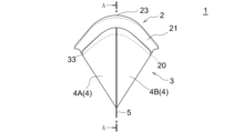
- FIG. 1 is a rear view of an eyewash container according to an embodiment of the present disclosure
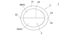
- FIG. 1 is a plan view of an eyewash container according to an embodiment of the present disclosure
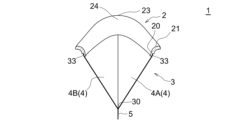
- FIG. Fig. 3 is a right side view of the eye wash container of the embodiment of the present disclosure
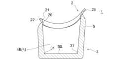
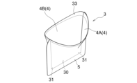
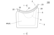
- FIG. 3 is a cross-sectional view (longitudinal cross-sectional view in the first direction) taken along the line AA in FIG. 2
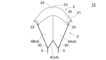
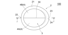
- FIG. 5 is a cross-sectional view taken along line BB of FIG. 4 (longitudinal cross-sectional view in a second direction perpendicular to the first direction);
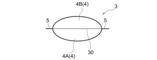
- FIG. 5 is a cross-sectional view (cross-sectional view) taken along line CC of FIG. 4; It is a perspective view of a storage part.
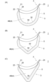
- (A) to (C) are longitudinal cross-sectional views in the first direction of the modified eye wash container.
- FIG. 4A is a perspective view and (B) a right side view of the eyewash container in a folded state according to the embodiment of the present disclosure;
- FIG. 4 is an explanatory diagram showing how the eye wash container of the embodiment of the present disclosure is used; It is the longitudinal cross-sectional view of the second direction of the eye wash container of a modification. It is a top view of the eye wash container of a modification.
- FIG. 14 is a plan view of a modified eye wash container of FIG. 13; FIG.
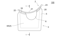
- FIG. 14 is a cross-sectional view (longitudinal cross-sectional view in the first direction) taken along line DD of FIG. 13;
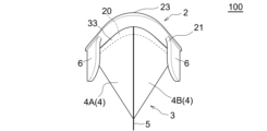
- FIG. 15 is a cross-sectional view (longitudinal cross-sectional view in the second direction) taken along line EE of FIG. 14;
- It is a top view of the eye wash container of a modification.
- FIG. 18 is a plan view of a modified eye wash container of FIG. 17;
- FIG. 18 is a rear view of the modified eye wash container of FIG. 17;
- FIG. 18 is a cross-sectional view (longitudinal cross-sectional view in the first direction) taken along line FF of FIG. 17;
- FIG. 19 is a cross-sectional view (longitudinal cross-sectional view in the second direction) taken along line GG of FIG. 18;
- the eye wash container of the present disclosure is used, for example, when washing the eyes with an eye wash solution to prevent eye diseases or to combat hay fever. It should be noted that the above-described purpose of use of the eye wash container of the present disclosure is merely an example.
- the eyewash solution is not particularly limited as long as it is a liquid that can be used for washing the eyes, and various known eyewash solutions can be used.
- the height direction of the eye wash container when the user uses the eye wash container with the face facing downward is defined as the up-down direction.
- the side corresponding to the inner corner of the eye (the end closer to the nose of the eye) when pressed around the user's eyes is the front side
- the outer corner of the eye (closer to the ear of the eye) is the front side.
- the side corresponding to the edge of the eyewash container is the back side
- the side where the eye wash container is viewed from above is the flat side
- the side when the eye wash container is viewed from the bottom is the bottom side
- the remaining two sides of the six sides are Side side.
- the direction of the inside of the eye wash container is defined as the inside
- the direction of the outside is defined as the outside.
- the eyewash container 1-7 illustrate one embodiment of the eye wash container of the present disclosure.
- the eye wash container 1 has a frame portion 2 and a storage portion 3 .
- the frame portion 2 is a portion that is pressed around the user's eyes.
- the storage part 3 is a part that stores an eyewash solution for washing the user's eyes. Each component of the eye wash container 1 will be described in detail below.
- the frame portion 2 has a frame-like shape with an inner opening, and is sized to fit the user's eyes and their surroundings in the opening.
- the shape of the frame portion 2 is generally elliptical in plan view in this embodiment.
- the shape of the frame portion 2 in a plan view is not particularly limited, and may be a circular shape, a rectangular shape such as a square or a rectangular shape, or a diamond shape.
- the frame portion 2 is not particularly limited, but in the present embodiment, a portion 22 corresponding to the inner corner of the eye (the end closer to the nose of the eye) and the outer corner of the eye (the closer to the ear of the eye) are provided at both ends in the longitudinal direction.
- the corresponding portion 23 is located on the end side of the tube, and the intermediate portion between them is formed so as to be convex downward and curved.
- a portion 23 corresponding to the outer corner of the eye of the frame portion 2 is positioned above the portion 22 corresponding to the inner corner of the eye.
- the frame part 2 has elasticity and flexibility so that it can be pressed against the user's eyes without gaps.
- various known resin materials used for the frame portion of a conventional eye wash container can be used. Examples include polyvinyl chloride, ABS resin, polyethylene, polycarbonate, polypropylene, polystyrene, Synthetic rubber, natural rubber, methacrylic resin, silicone rubber, polyurethane, polytrifluoroethylene, thermoplastic elastomer, polyvinyl alcohol, polytetrafluoroethylene, epoxy resin, polyamide, polyacetal, polyvinylidene fluoride, urea resin, polyvinyl acetate, At least one resin selected from polyethylene terephthalate, polyethylene naphthalate, phenol resin, alkyd resin, melamine resin, and acrylic resin can be used.
- the frame portion 2 includes, but is not limited to, a vertically extending lower portion 20 and an upper portion 21 extending on the lower portion 20 so as to be inclined radially outward.
- the lower portion 20 is a portion to which the storage portion 3 is joined, and the upper portion 21 is a portion that abuts around the user's eyes.
- the entire frame portion 2 is formed to have elasticity and flexibility, but only the upper portion 21 is formed to have elasticity and flexibility, and the lower portion 20 is more flexible than the upper portion 21. It may be formed to be hard and rigid.
- the lower portion 20 can be formed using various known hard resin materials used in the reservoir of conventional eye wash containers, for example, thermoplastic resins such as polypropylene and polyethylene.
- the reservoir 3 is made of a liquid-impermeable and flexible resin film and has a bag shape.
- the upper end of the storage portion 3 is open, and an upper end portion 33 of the storage portion 3 forming the periphery of the upper end opening (a portion having a predetermined width (length in the vertical direction) along the upper edge of the storage portion 3). is joined to the lower portion 20 of the frame portion 2 over the entire circumference.
- the method of joining the upper end portion 33 of the storage portion 3 to the frame portion 2 is not particularly limited. can be used.
- a hard resin film can be used as long as it has flexibility, but it is preferable to use a thin, soft and flexible resin film.
- a soft resin film for example, a soft packaging material that is generally used for packaging foods, medicines, etc. can be used.
- the resin that forms the resin film include polyolefins such as polyethylene and polypropylene, polyethylene terephthalate, nylon, and the like.
- polyamides cellophane, polyvinyl chloride, polyvinylidene chloride, ethylene-vinyl acetate copolymers, ethylene ethyl acrylate copolymers, ethylene acrylic acid copolymers, ethylene methacrylic acid copolymers, ionomers, and the like.
- the thickness of the reservoir 3 is not particularly limited, but is preferably 0.02 mm or more and 0.8 mm or less, more preferably 0.05 mm or more and 0.5 mm or less, and 0.05 mm or more and 0.25 mm or less. Even more preferred.
- the reservoir 3 is formed of two resin films 4A and 4B in this embodiment.
- the two resin films 4A and 4B have substantially the same size and shape.
- the storage part 3 can be formed in a bag shape.
- the storage portion 3 is moved to the frame portion 2.
- the method of joining the resin films is not particularly limited, and various known methods such as adhesion using an adhesive or pressure-sensitive adhesive, heat welding, ultrasonic welding, and the like can be used.
- the width of the joint portion 5 of the resin film in the storage portion 3 is not particularly limited, but considering the strength of the storage portion 3, it is preferably 2 mm or more and 10 mm or less, more preferably 2 mm or more and 8 mm or less.
- the vertical cross-sectional shape of the reservoir 3 viewed from the side is, in the present embodiment, a platform that narrows downward. Shape.
- the longitudinal cross-sectional shape of the storage part 3 in the first direction is not particularly limited, and may be rectangular, square (rectangular) or other quadrilateral, triangular, semicircular, semielliptical, or the like. Various shapes are possible.
- the vertical cross-sectional shape is the cross-sectional shape along the vertical direction.
- the storage part 3 is not particularly limited, but has a tapered shape such that the lower end including at least the bottom 30 in the cross-sectional view (shown in FIG. 7) gradually becomes smaller as it goes downward.
- the cross-sectional shape is the shape of the cross section along the horizontal direction.
- the storage part 3 has a V-shape with a sharp lower end when viewed from the front and rear sides (shown in FIG. 6 and referred to as the “longitudinal cross-sectional shape in the second direction” in the present disclosure). , and the entire storage portion 3 has the tapered shape described above.
- the liquid storage part 3 has a quadrangular shape such as a trapezoid when viewed in vertical cross section in the first direction, so that the bottom 30 extends substantially horizontally linearly between the front side and the back side (Fig. 5 to 7), the reservoir 3 has a shape that gradually widens upward from a linear bottom 30 to both side surfaces.
- the shape of the vertical cross section of the storage portion 3 in the first direction is a quadrilateral shape such as a trapezoid.
- the lower end including at least the bottom 30 has a rounded shape (e.g. circular, elliptical, U-shaped)
- the bottom 30 of the reservoir 3 is convex downward between the front side and the back side. It extends linearly while curving.
- the shape of the vertical cross-section of the storage part 3 in the first direction is a shape (for example, a rocket shape) with a pointed lower end including at least the bottom 30 as shown in FIG.
- the bottom 30 linearly extends between the front side and the back side while forming a downward convex and bending.
- the longitudinal cross-sectional shape of the reservoir 3 in the first direction is triangular as shown in FIG. 9C
- the reservoir 3 has a conical shape and the bottom 30 of the reservoir 3 is point-shaped .
- the storage part 3 has the above-described V shape in the longitudinal cross-sectional shape in the second direction when viewed from the front side and the back side.
- the shape may be V-shaped.
- the reservoir 3 is not particularly limited, but is wholly or partly transparent or translucent, so that the amount of eye wash liquid in the reservoir 3 can be confirmed from the outside.
- the eye wash liquid is injected into the bag-shaped reservoir 3 of the eye wash container 1 from a liquid container containing the eye wash solution prepared separately from the eye wash container.
- the storage part 3 of the eye wash container 1 is folded, the storage part 3 is expanded to form a bag.
- the storage part 3 is made of a resin film and formed in a bag shape, a strong force is not applied to the storage part 3 when squeezing the bag-shaped storage part 3 during use.
- the storage part 3 can be easily deformed, and the eye wash liquid in the storage part 3 can be pushed up and made to flow. Therefore, according to the eyewash container 1 of the present embodiment, almost no force is applied to the frame portion 2 during eyewashing, and deformation of the frame portion 2 can be suppressed, so that the frame portion 2 maintains close contact with the user's face. , it is possible to suppress the leakage of the eyewash liquid from between the frame part 2 and the face when washing the eyes.
- the storage part 3 is made of a resin film and has low rigidity. Therefore, according to the eye wash container 1 of the present embodiment, when the eye wash container 1 is attached to the mouth of the liquid container and is distributed and stored, the eye wash container 1 may be slammed against the floor or the like due to the drop of the liquid container. Even if the storage part 3 receives an impact, the storage part 3 is easily deformed, so that the eye wash container 1 is less likely to be damaged.
- the storage part 3 is bag-shaped and has no shape retention property, that is, it has high rigidity and is difficult to deform, and has high elasticity and does not retain its original shape even if it is deformed. Since it is not a property that can be restored to its shape, it can be easily deformed and reduced in size by folding it as shown in FIG. Therefore, according to the eye wash container 1 of this embodiment, the eye wash container 1 is not bulky when carried.
- the eye wash container 1 of the present embodiment does not have the shape retention property of the storage portion 3, even if the eye wash solution vigorously hits the inner surface of the storage portion 3 when injecting the eye wash solution from the liquid container, The momentum of the liquid is relaxed. Therefore, according to the eye wash container 1 of the present embodiment, the eye wash container 1 splashes when injected into the eye wash container 1, and the hand of the user holding the eye wash container 1 and the table on which the eye wash container is placed are not stained by the splashed eye wash solution. can be suppressed.
- the cleaning container 1 of the present embodiment can solve the above-described problems of the present disclosure.
- the reservoir 3 of the cleaning container 1 of the present embodiment is made of a resin film, the amount of resin used can be reduced compared to the reservoir of the conventional eye wash container, which has the advantage of being environmentally friendly.
- the eye wash container 1 of the present embodiment has a tapered lower end portion including at least the bottom 30 of the storage portion 3 in a cross-sectional view that gradually becomes smaller downward.
- the bottom 30 of the storage part 3 has a linear or point-like shape and is pointed at the lower end. Since the bottom 30 of the reservoir 3 is narrow as described above, according to the eye wash container 1 of the present embodiment, the eye can be washed with a small amount of eye wash solution, and the eye wash container 1 can be easily folded when carrying. Furthermore, since the force applied to the storage part 3 when squeezing the storage part 30 can be easily adjusted, it is possible to easily adjust the flow rate and momentum of the eye wash liquid brought into contact with the eye during eye washing.
- the eye wash container 1 needs to be sanitary in view of its intended use, and it is preferable that dirt and foreign matter removed from the eye by the eye wash can be easily visually confirmed. Since the eye wash container 1 of the present embodiment has a tapered shape in which the lower end portion including at least the bottom 30 of the reservoir 3 is pointed, dirt and foreign substances removed from the eye by washing the eyes are likely to accumulate in the bottom 30 of the reservoir 3. Structure. Therefore, according to the eye wash container 1 of the present embodiment, the user can visually confirm dirt and foreign matter removed from the eye, and the eye wash container 1 can be sanitarily cleaned and stored.
- the reservoir 3 has a rectangular shape such as a trapezoid in the first vertical cross-sectional shape parallel to the direction in which the linear bottom 30 extends.
- the storage part 3 has an outer shape in which the lower end including at least the bottom 30 is bent to have corners 31 at the left and right ends of the bottom 30 .
- the lower end portion including at least the bottom 30 is curved downward or convex downward and pointed, and the lower end of the storage part 3 is bent to have an apex 32 at the center of the bottom 30, wash the eyes. Dirt and foreign matter removed from the eye naturally accumulates at the apex 32 of the bottom 30 of the reservoir 3. Therefore, even in this case, the user can easily visually confirm the dirt or foreign matter removed from the eye.
- the eye wash container of the present disclosure is not limited to the above embodiment, and various modifications are possible without departing from the scope of the present disclosure. That is, the eye wash container of the modified example illustrated below can solve the above-described problems of the present disclosure, like the eye wash container 1 of the above embodiment.
- the reservoir 3 is formed of two resin films 4A and 4B.
- the reservoir 3 can be made of a single resin film.
- the storage part 3 can be formed into a bag shape by joining the folded parts of one folded resin film to each other and joining the left and right side edges to each other. Then, by joining the two upper edges of the folded resin film that are not joined to each other to the lower part 20 of the frame part 2 with a predetermined width, the storage part 3 can be fixed to the frame part 2. can.
- the storage part 3 has a tapered shape with a pointed lower end so that the lower end including at least the bottom 30 in the cross-sectional view gradually becomes smaller as it goes downward,
- a bottom 30 of the reservoir 3 extends substantially horizontally linearly between the front side and the back side.
- the reservoir 3 can be formed by three resin films 4A, 4B, and 4C.
- the eye wash container 10 of this modified example two resin films 4A and 4B having substantially the same size and shape forming the side surface of the storage portion 3 are superimposed on each other, and the other one forming the bottom surface of the storage portion 3.
- the resin film 4C is folded in two and sandwiched between the lower portions of the two resin films 4A and 4B with the folded portion directed upward.
- the bottom surface of the storage portion 3 is formed, and the left and right side edges of the two resin films 4A and 4B are formed above the resin film 4C.
- the storage part 3 can be formed into a bag shape. Then, the storage part 3 is fixed to the frame part 2 by joining the upper edges of the two resin films 4A and 4B forming the side surfaces, which are not joined to each other, to the lower part 20 of the frame part 2 with a predetermined width. can be done.
- the storage part 3 is formed with two bottoms 30 . Also in the eye wash container 10 of this modified example, the storage part 3 has a tapered shape with a pointed lower end so that the lower end including at least the bottom 30 in the cross-sectional view gradually becomes smaller as it goes downward. , the two bottoms 30 of the reservoir 3 extend substantially horizontally linearly between the front side and the back side, respectively.
- the bottom 30 of the reservoir 3 has a linear shape.
- the storage part 3 has a tapered shape so that the lower end including at least the bottom 30 in a cross-sectional view gradually becomes smaller as it goes downward, but the lower end is pointed. It doesn't have to be.
- the bottom 30 of the reservoir 3 is planar rather than linear, and the bottom 30 of the reservoir 3 extends substantially horizontally between the front side and the back side. .
- the storage part 3 has a tapered shape in a cross-sectional view so that the lower end including at least the bottom 30 gradually becomes smaller downward.
- the reservoir 3 may not have a tapered shape.
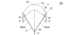
- the eye wash container 100 may have a pair of opposing finger rests 6 on the frame 2 .
- the pair of finger rests 6 may be formed integrally with the frame portion 2 or may be formed separately from the frame portion 2 and attached to the frame portion 2 .
- the pair of finger rests 6 may be arranged inside the reservoir 3 or may be arranged outside the reservoir 3 .
- the pair of finger rests 6 When the pair of finger rests 6 are arranged inside the storage part 3, as shown in FIGS. preferably. As a result, the pair of finger rests 6 can be placed along the tapered inner surface of the reservoir 3 .
- the pair of finger rests 6 When the pair of finger rests 6 are arranged outside the storage part 3, the pair of finger rests 6 may extend vertically from the frame part 2 as shown in FIGS. You may incline with respect to a vertical direction so that it may fall inwardly or outwardly from the part 2.
- FIG. 1 When the pair of finger rests 6 are arranged outside the storage part 3, the pair of finger rests 6 may extend vertically from the frame part 2 as shown in FIGS. You may incline with respect to a vertical direction so that it may fall inwardly or outwardly from the part 2.
- the pair of finger contact portions 6 are formed in a shape and size that allow the user to pinch and hold the pair of finger contact portions 6 with a thumb or forefinger.
- the eye wash container 100 When the eye wash container 100 is pressed around the eyes, the user can hold the eye wash container 100 easily by holding the pair of finger rests 6 between the fingers.
- the eye wash container 100 can be pressed against the face without gaps, and the adhesion of the eye wash container 100 to the face can be improved.
Landscapes
- Health & Medical Sciences (AREA)
- Public Health (AREA)
- Epidemiology (AREA)
- Pain & Pain Management (AREA)
- Physical Education & Sports Medicine (AREA)
- Rehabilitation Therapy (AREA)
- Life Sciences & Earth Sciences (AREA)
- Animal Behavior & Ethology (AREA)
- General Health & Medical Sciences (AREA)
- Veterinary Medicine (AREA)
- Ophthalmology & Optometry (AREA)
- Devices For Medical Bathing And Washing (AREA)
Abstract
【課題】使用時に貯留部をスクイズして変形させた際にフレーム部の変形を抑制してフレーム部の顔への密着性が損なわれないようにする洗眼容器を提供する。 【解決手段】洗眼の際に使用される洗眼容器1は目の周囲に当てられるフレーム部2と、洗眼液を内部に貯留可能な樹脂フィルム製の袋状の貯留部3であって、上端部が全周にわたってフレーム部2に接合される貯留部3と、を備える。
Description
本開示は、洗眼液で眼を洗浄する際に使用される洗眼容器に関する。
眼病予防や花粉症対策などのため、洗眼液で眼を洗うことが従来から行われており、洗眼する際に使用される洗眼容器として、洗眼液を貯留可能なカップ状の貯留部と、カップ状の貯留部の上端縁に全周にわたって設けられたフレーム部とで構成された洗眼容器が知られている。洗眼液は、別途に用意される液体収容器に収容されており、液体収容器から洗眼容器のカップ状部に注入される。
特許文献1には、カップ状の貯留部及びフレーム部が弾性変形可能な柔軟材料により一体に成形された洗眼容器が開示されている。ユーザは、特許文献1の洗眼容器のカップ状の貯留部を指で掴み、顔を下に向けた状態でフレーム部を目の周囲に隙間なく押し当てた後、指でカップ状の貯留部をスクイズする。これにより、貯留部内の洗眼液が押し上げられ、流動する洗眼液が眼に接触することにより、洗眼することができる。
特許文献2には、剛性を有するカップ状の貯留部の上端縁に柔軟なフレーム部が固定された洗眼容器が開示されている。ユーザは、特許文献2の洗眼容器のカップ状の貯留部を指で掴み、顔を下に向けた状態でフレーム部を目の周りに隙間なく押し当てた後、顔を上に向けて眼を洗眼液に浸しながら瞬きする。これにより、貯留部内の洗眼液が流動し、洗眼することもできる。
特許文献1に記載の洗眼容器は、フレーム部及びカップ状の貯留部が弾性変形可能な柔軟材料により一体に成形されているため、使用時にカップ状の貯留部をスクイズして変形させた際にフレーム部にも力が作用して変形する。これにより、フレーム部が歪んで顔への密着性が損なわれると、使用中にフレーム部と顔との間に隙間が生じてこの隙間から洗眼液が漏れ出るおそれがある。
特許文献2に記載の洗眼容器は、カップ状の貯留部が剛性を有していてスクイズできないため、ユーザは顔を上に向けた状態でフレーム部を目の周囲に押し当てるが、瞬きしながらフレーム部を隙間なく顔に押し当て続けることは容易ではなく、使用中にフレーム部と顔との間に隙間が生じてこの隙間から洗眼液が漏れ出るおそれがある。加えて、洗眼容器は、液体収容器の口部に着脱可能に装着されるものが多く、この場合には液体収容器の口部に装着された状態で流通、保管される。しかし、口部に洗眼容器が装着された液体収容器を床などに落としてしまい、運悪く洗眼容器が下を向いた状態で床などに叩きつけられると、剛性のあるカップ状の貯留部が強い衝撃を受けてひびが入ったり割れたりするなど破損するおそれがある。
また特許文献1及び2に記載の洗眼容器は、カップ状の貯留部に保形性があるために折り畳むなどして保管することができず、携帯する際に洗眼容器が嵩張るおそれがある。そのうえ、特許文献1及び2に記載の洗眼容器は、液体収容器から洗眼液を注入する際に洗眼液がカップ状の貯留部の内壁面に勢いよく当たると、その保形性により洗眼液が飛び跳ね、洗眼容器を持つ手や洗眼容器を置いた台などが飛び跳ねた洗眼液により汚れるおそれがある。
本開示は、上記課題を解決することができる洗眼容器の提供を目的とする。
本開示の洗眼容器は、洗眼の際に使用されるものである。本開示の洗眼容器は、目の周囲に当てられるフレーム部と、洗眼液を内部に貯留可能な樹脂フィルム製の袋状の貯留部であって、上端部が全周にわたって前記フレーム部に接合される貯留部と、を備える、ことを特徴とする。
本開示の洗眼容器において好ましくは、前記貯留部の少なくとも底を含む下端部は、横断面視形状が下方に向かうに連れて次第に小さくなる先細りの形状を呈し、前記底は線状又は点状を呈する、ことを特徴とするように構成することができる。
また、本開示の洗眼容器において好ましくは、前記貯留部の前記底が線状を呈しており、前記底が延びる方向に平行な縦断面視形状において、前記貯留部の少なくとも前記底を含む下端部は、前記底が頂点を有するように下に凸をなして折れ曲がる外形を呈する、ことを特徴とするように構成することができる。
また、本開示の洗眼容器において好ましくは、前記貯留部の前記底が線状を呈しており、前記底が延びる方向を横から見た形状において、前記貯留部の少なくとも前記底を含む下端部は、前記底の左右の端に角を有するように折れ曲がる外形を呈する、ことを特徴とするように構成することができる。
また、本開示の洗眼容器において好ましくは、前記貯留部は、対向する二枚の樹脂フィルムの外周縁同士を上端縁及び左右の側縁を互いに接合することで袋状に形成され、前記二枚の樹脂フィルムの互いに接合されていない上端縁が所定の幅でもって前記フレーム部に接合されている、ことを特徴とするように構成することができる。
また、本開示の洗眼容器において好ましくは、前記フレーム部には、対向する一対の指当て部が前記貯留部の内側又は外側に配置されるように設けられる、ことを特徴とするように構成することができる。
本開示の洗眼容器によれば、貯留部が樹脂フィルム製で袋状に形成されているため、使用時に袋状の貯留部をスクイズする際に貯留部に強い力をかけなくても貯留部を容易に変形させることができる。よって、貯留部のスクイズの際にフレーム部にほとんど力がかからず、フレーム部の変形を抑制できるので、フレーム部は顔への密着性が維持され、フレーム部と顔との間から洗眼液が漏れ出るのを抑制することができる。
また本開示の洗眼容器によれば、貯留部は樹脂フィルム製で剛性が低いため、液体収容器の口部に装着された状態で流通、保管された際に、液体収容器の落下などによって洗眼容器が床などに叩きつけられて貯留部が衝撃を受けても貯留部は容易に変形する。よって、洗眼容器が破損するおそれが低い。
また本開示の洗眼容器によれば、貯留部は樹脂フィルム製の袋状で保形性がないため、折り畳むなど容易に変形させてサイズを小さくすることができる。よって、洗眼容器を携帯する際に洗眼容器が嵩張らない。加えて、袋状の貯留部は保形性がないことから、液体収容器から洗眼液を注入する際に洗眼液が袋状の貯留部の内側面に勢いよく当たっても、洗眼液の勢いが緩和される。よって、洗眼液が洗眼容器への注入時に飛び跳ねて、洗眼容器を持つ手や洗眼容器を置いた台などが飛び跳ねた洗眼液により汚れるのを抑制することができる。
本開示の洗眼容器は、例えば眼病予防や花粉症対策のために洗眼液により眼を洗う際に使用されるものである。なお、本開示の洗眼容器の上述した使用目的はあくまでも一例である。洗眼液は、洗眼に用いることができる液体であれば特に限定されず、公知の種々の洗眼液を用いることができる。
以下、本開示の洗眼容器の実施形態について、添付図面を参照して説明する。なお、本開示では、ユーザが顔を下に向けた状態で洗眼容器を使用する状態(フレーム部を上に貯留部を下にした状態)における洗眼容器の高さ方向を上下方向とする。また、洗眼容器において、ユーザの目の周囲に押し当てた際の目頭(目の鼻に近い方の端)側に対応する部分が真正面となる側を正面側、目尻(目の耳に近い方の端)側に対応する部分が真正面となる側を背面側とし、洗眼容器を上から見る側を平面側、洗眼容器を下から見る側を底面側とし、六面の残りの二面側を側面側とする。また、洗眼容器の内部の方向を内側、外部の方向を外側とする。
洗眼容器
図1から図7は、本開示の洗眼容器の一実施形態を示す。洗眼容器1は、フレーム部2及び貯留部3を備える。フレーム部2は、ユーザの目の周囲に押し当てられる部分である。貯留部3は、ユーザの眼を洗うための洗眼液を貯留する部分である。以下、洗眼容器1の各構成部材について詳細に説明する。
フレーム部
図1から図6に示すように、フレーム部2は、内側に開口を有する枠状を呈しており、当該開口にユーザの目及びその周囲が収まる大きさに形成されている。フレーム部2の形状は、本実施形態では平面視で概ね楕円形状である。フレーム部2の平面視形状は、特に限定されるものではなく、円形状、正方形や長方形の矩形状、菱形形状などの他の形状であってもよい。
フレーム部2は、特に限定されるものではないが、本実施形態では長軸方向の両端に目頭(目の鼻に近い方の端)側に対応する部分22及び目尻(目の耳に近い方の端)側に対応する部分23が位置し、これらの間にある中間部分が下に凸をなして湾曲するように形成されている。また、フレーム部2の目尻側に対応する部分23は、目頭側に対応する部分22よりも上方に位置している。これにより、フレーム部2をユーザの目の周囲にフィットさせることができ、フレーム部2を目の周囲に良好に密着させることができる。
フレーム部2は、ユーザの目の周囲に隙間なく押し当てることができるように、弾性及び柔軟性を有する。フレーム部2を形成する材料としては、従来の洗眼容器のフレーム部に用いられる公知の種々の樹脂材料を用いることができるが、例えば、ポリ塩化ビニル、ABS樹脂、ポリエチレン、ポリカーボネート、ポリプロピレン、ポリスチレン、合成ゴム、天然ゴム、メタクリル樹脂、シリコーンゴム、ポリウレタン、ポリ三フッ化エチレン、熱可塑性エラストマー、ポリビニルアルコール、ポリテトラフルオロエチレン、エポキシ樹脂、ポリアミド、ポリアセタール、ポリフッ化ビニリデン、尿素樹脂、ポリ酢酸ビニル、ポリエチレンテレフタレート、ポリエチレンナフタレート、フェノール樹脂、アルキド樹脂、メラミン樹脂、アクリル樹脂から選択される少なくとも一種の樹脂を挙げることができる。
フレーム部2は、特に限定されるものではないが、上下方向に延びる下部20と、下部20上に径方向外向きに傾斜するように延びる上部21とを含む。下部20は、貯留部3が接合される部分であり、上部21は、ユーザの目の周囲に当接する部分である。
上部21は、特に限定されるものではないが、本実施形態では目尻側に当接する部分24の幅がそれ以外の部分の幅よりも広くなるように形成されている。フレーム部2をユーザの目の周囲に押し当てた際、目尻の近傍から洗眼液が漏れやすいが、上部21の目尻側に当接する部分24の幅を広くすることにより、目尻の近傍からの洗眼液の漏れを抑制することができる。また、上部21の目尻側に当接する部分以外の部分の幅を狭くすることにより、鼻などが邪魔することなく上部21を目の周囲に当接させることができる。
なお、フレーム部2は、本実施形態ではその全体が弾性及び柔軟性を有するように形成されているが、上部21だけを弾性及び柔軟性を有するように形成し、下部20は上部21よりも硬くて剛性を有するように形成してもよい。この場合に下部20は、従来の洗眼容器の貯留部に用いられる公知の種々の硬質の樹脂材料、例えば、ポリプロピレン、ポリエチレンなどの熱可塑性樹脂を用いて形成することができる。
貯留部
図1から図8に示すように、貯留部3は、液不透過性でありかつ可撓性を有する樹脂フィルム製であり、袋状を呈している。貯留部3は、上端が開口しており、この上端開口の周縁をなす貯留部3の上端部33(貯留部3の上端縁に沿った所定の幅(上下方向の長さ)を有する部分)が全周にわたってフレーム部2の下部20に接合されている。貯留部3の上端部33をフレーム部2に接合する方法は、特に限定されるものではなく、例えば、接着剤や粘着剤による接着の他、熱溶着や超音波溶着など、公知の種々の方法を用いることができる。
貯留部3を形成する樹脂フィルム4は、可撓性を有していれば硬質の樹脂フィルムを用いることもできるが、薄くて柔らかい軟質の樹脂フィルムを用いることが好ましい。軟質の樹脂フィルムとしては、例えば一般に食品や薬剤などの包装に用いられる軟包装材を用いることができ、樹脂フィルムを形成する樹脂としては、例えば、ポリエチレンやポリプロピレンなどのポリオレフィン、ポリエチレンテレフタレート、ナイロンなどのポリアミド、セロハン、ポリ塩化ビニル、ポリ塩化ビニリデン、エチレン-酢酸ビニル共重合体、エチレンエチルアクリレート共重合体、エチレンアクリル酸共重合体、エチレンメタクリル酸共重合体、アイオノマーなどを挙げることができる。
貯留部3を形成する樹脂フィルム4は、厚みが小さいほど貯留部3を柔らかくできる一方で、厚みが小さ過ぎると貯留部3の強度が低下する。そのため、貯留部3の厚みは、特に限定されるものではないが、0.02mm以上0.8mm以下が好ましく、0.05mm以上0.5mm以下がより好ましく、0.05mm以上0.25mm以下がさらにより好ましい。
貯留部3は、特に限定されるものではないが、本実施形態では二枚の樹脂フィルム4A,4Bにより形成されている。二枚の樹脂フィルム4A,4Bは大きさ及び形状がほぼ同じである。互いに重ね合わされることにより対向する二枚の樹脂フィルム4A,4Bの下端縁及び左右の側縁を互いに接合することで、貯留部3を袋状に形成することができる。そして、二枚の樹脂フィルム4A,4Bの互いに接合されていない上端縁を所定の幅(上下方向の長さ)でもってフレーム部2の下部20に接合することで、貯留部3をフレーム部2に固定することができる。樹脂フィルムの接合方法は、特に限定されるものではなく、例えば、接着剤や粘着剤による接着の他、熱溶着や超音波溶着など、公知の種々の方法を用いることができる。
貯留部3における樹脂フィルムの接合部5の幅は、特に限定されるものではないが、貯留部3の強度を考慮すれば、2mm以上10mm以下が好ましく、2mm以上8mm以下がより好ましい。
貯留部3の側面側から見た縦断面視形状(図5に示す、本開示では「第一方向の縦断面視形状」という)は、本実施形態では下方に向かうに連れて幅狭の台形状である。貯留部3の第一方向の縦断面視形状は、特に限定されるものではなく、長方形状や正方形状(矩形状)などの他の四角形状、三角形状、半円形状、半楕円形状など、種々の形状とすることができる。なお、本開示において縦断面視形状とは、鉛直方向に沿った断面の形状である。
貯留部3は、特に限定されるものではないが、横断面視形状(図7に示す)において少なくとも底30を含む下端部が下方に向かうに連れて次第に小さくなるように、先細りの形状を呈している。なお、本開示において横断面視形状とは、水平方向に沿った断面の形状である。
本実施形態では、貯留部3は、正面側及び背面側から見た縦断面視(図6に示す、本開示では「第二方向の縦断面視形状」という)において下端が尖るV字形状を呈しており、貯留部3の全体が上述した先細りの形状を呈している。これにより、貯液部3は、第一方向の縦断面視形状が台形状などの四角形状であるために底30が正面側及び背面側の間でほぼ水平に線状に延びていて(図5から図7に示す)、貯留部3は線状の底30から上方に向かって両側面側に次第に広がる形状を呈している。
本実施形態では貯留部3の第一方向の縦断面視形状が台形状などの四角形状であるが、貯留部3の第一方向の縦断面視形状が図9(A)に示すような、少なくとも底30を含む下端部が先の丸い形状(例えば円形状、楕円形状、U字形状)である場合は、貯留部3の底30は正面側及び背面側の間を下に凸をなして湾曲しながら線状に延びる。貯留部3の第一方向の縦断面視形状が図9(B)に示すような、少なくとも底30を含む下端部が先の尖った形状(例えばロケット形状)である場合は、貯留部3の底30は正面側及び背面側の間を下に凸をなして屈曲しながら線状に延びる。貯留部3の第一方向の縦断面視形状が図9(C)に示すような、三角形状である場合は、貯留部3は錐形状をなし、貯留部3の底30は点状である。
貯留部3は、本実施形態では、正面側及び背面側から見た第二方向の縦断面視形状において上述したV字形状を呈しているが、側面側から見た第一方向の縦断面視形状においてV字形状を呈していてもよい。
貯留部3は、特に限定されるものではないが、全体又は一部が透明又は半透明であり、これにより外部から貯留部3内の洗眼液の量を確認することができる。
洗眼容器の使用方法
次に、上述した洗眼容器1の使用方法について説明する。まず、洗眼容器とは別途に用意される洗眼液を収容した液体収容器から、洗眼容器1の袋状の貯留部3に洗眼液を注入する。なお、図10に示すように、洗眼容器1の貯留部3が折り畳まれている場合は、貯留部3を広げて袋状とする。
次に、フレーム部2又は貯留部3を指で挟み持ち、顔を下に向けた状態でフレーム部2を目の周囲に隙間なく押し当てる。そして、図11に示すように、この状態で貯留部3を指でスクイズして貯留部3内の洗眼液を押し上げ、流動させた洗眼液を眼に接触させる。指による貯留部3のスクイズを繰り返し行い、貯留部3内の洗眼液を眼に繰り返し接触させることにより、眼に付着した汚れや、花粉、埃などの異物を洗い流して洗眼することができる。
なお、図示は省略するが、貯留部3を指で掴み、顔を下に向けた状態でフレーム部2を目の周りに隙間なく押し当てた後に顔を上に向け、眼を洗眼液に浸し続けながら瞬きすることによって洗眼液を流動させることにより、眼に付着した汚れや、花粉、埃などの異物を洗い流して洗眼することもできる。
洗眼容器による作用・効果
上述した本実施形態の洗眼容器1は、貯留部3が樹脂フィルム製で袋状に形成されているため、使用時に袋状の貯留部3をスクイズする際に貯留部3に強い力をかけなくても貯留部3を容易に変形させて、貯留部3内の洗眼液を押し上げて流動させることができる。よって、本実施形態の洗眼容器1によれば、洗眼時にフレーム部2にほとんど力がかからず、フレーム部2の変形を抑制できるので、フレーム部2はユーザの顔への密着性が維持され、洗眼時にフレーム部2と顔との間から洗眼液が漏れ出るのを抑制することができる。
また本実施形態の洗眼容器1は、貯留部3が樹脂フィルム製で剛性が低い。そのため、本実施形態の洗眼容器1によれば、液体収容器の口部に装着された状態で流通、保管された際に、液体収容器の落下などによって洗眼容器1が床などに叩きつけられて貯留部3が衝撃を受けても、貯留部3は容易に変形するので、洗眼容器1が破損するおそれが低い。
また本実施形態の洗眼容器1は、貯留部3が樹脂フィルム製の袋状で保形性がない、つまりは、剛性が高くて変形しにくい性質や、弾性が高くて変形しても元の形状に復元できる性質ではないため、図10に示すように折り畳むなどすることにより容易に変形させてサイズを小さくすることができる。よって、本実施形態の洗眼容器1によれば、洗眼容器1を携帯する際に嵩張らない。
また本実施形態の洗眼容器1は、貯留部3の保形性がないことから、液体収容器から洗眼液を注入する際に洗眼液が貯留部3の内側面に勢いよく当たっても、洗眼液の勢いが緩和される。よって、本実施形態の洗眼容器1によれば、洗眼液が洗眼容器1への注入時に飛び跳ねて、洗眼容器1を持つユーザの手や洗眼容器を置いた台などが飛び跳ねた洗眼液により汚れるのを抑制することができる。
以上の通り、本実施形態の洗浄容器1は、本開示の上述した課題を解決することができる。加えて、本実施形態の洗浄容器1は、貯留部3が樹脂フィルム製であるため、従来の洗眼容器の貯留部と比べて樹脂の使用量を削減することができるため、環境にやさしいという利点がある。
加えて、本実施形態の洗眼容器1は、図6及び図7に示すように、貯留部3の少なくとも底30を含む下端部が横断面視形状で下方に向かうに連れて次第に小さくなる先細りの形状を呈しており、貯留部3の下端部は底30が線状又は点状をなして尖っている。このように貯留部3の底30が狭いため、本実施形態の洗眼容器1によれば、少量の洗眼液で洗眼することができるうえ、洗眼容器1の携帯の際に折り畳みやすくなる。さらに、貯留部30をスクイズする際に貯留部3に加える力を調整しやすいため、洗眼時に眼に接触させる洗眼液の流量や勢いなどを容易に調整することができる。
また、洗眼容器1は、その使用目的上、衛生的に使用できることが必要であり、洗眼により眼から除去された汚れや異物を目視により容易に確認できることが好ましい。本実施形態の洗眼容器1は、貯留部3の少なくとも底30を含む下端部が尖る先細りの形状であることにより、洗眼により眼から除去された汚れや異物が貯留部3の底30に溜まりやすい構造である。よって、本実施形態の洗眼容器1によれば、ユーザは眼から除去された汚れや異物を目視で確認することができ、洗眼容器1の衛生的な洗浄・保管が可能となる。
加えて、本実施形態の洗眼容器1は、図5に示すように、貯留部3が線状の底30が延びる方向に平行な第一の縦断面視形状において台形状などの四角形状を呈しており、貯留部3の少なくとも底30を含む下端部が底30の左右の端に角31を有するように折れ曲がる外形を呈している。これにより、洗眼容器1を傾けると、洗眼により眼から除去された汚れや異物が貯留部3の底30の角31に溜まる。よって、本実施形態の洗眼容器1によれば、ユーザは眼から除去された汚れや異物を目視で容易に確認することができる。
一方で、図9(A)や図9(B)に示すように、貯留部3が線状の底30が延びる方向に平行な第一の縦断面視形状において、少なくとも底30を含む下端部が下に凸をなして湾曲する又は下に凸をなして尖る形状を呈しており、貯留部3の下端部が底30の中央に頂点32を有するように折れ曲がる外形を呈する場合は、洗眼により眼から除去された汚れや異物が貯留部3の底30の頂点32に自然に溜まる。よって、この場合もユーザは眼から除去された汚れや異物を目視で容易に確認することができる。
洗眼容器の変形例
以上、本開示の洗眼容器の一実施形態について説明したが、本開示の洗眼容器は上記実施形態に限定されるものではなく、本開示の趣旨を逸脱しない限りにおいて種々の変形が可能である。つまり、以下に例示する変形例の洗眼容器は、上記実施形態の洗眼容器1と同様に、本開示の上述した課題を解決することができる。
上記実施形態の洗眼容器1は、貯留部3が二枚の樹脂フィルム4A,4Bで形成されている。変形例として、図示は省略するが、貯留部3を一枚の樹脂フィルムにより形成することもできる。この変形例の洗眼容器では、折り返された一枚の樹脂フィルムの折り返し部を互いに接合するとともに、左右の側縁を互いに接合することで、貯留部3を袋状に形成することができる。そして、折り返された一枚の樹脂フィルムの互いに接合されていない二つの上端縁を所定の幅でもってフレーム部2の下部20に接合することで、貯留部3をフレーム部2に固定することができる。この変形例の洗眼容器においても、貯留部3は、横断面視形状において少なくとも底30を含む下端部が下方に向かうに連れて次第に小さくなるように、下端が尖る先細りの形状を呈しており、貯留部3の底30は正面側及び背面側の間でほぼ水平に線状に延びている。
また他の変形例として、図12に示すように、貯留部3を三枚の樹脂フィルム4A,4B,4Cにより形成することもできる。この変形例の洗眼容器10では、貯留部3の側面をなす大きさ及び形状がほぼ同じの二枚の樹脂フィルム4A,4Bが互いに重ね合わされており、貯留部3の底面をなす他の一枚の樹脂フィルム4Cが二つ折りにされかつ折り返し部を上方に向けた状態で二枚の樹脂フィルム4A,4Bの下部の間に挟まれている。樹脂フィルム4Cの外周縁を二枚の樹脂フィルム4A,4Bに接合することで、貯留部3の底面が形成され、樹脂フィルム4Cよりも上方において二枚の樹脂フィルム4A,4Bの左右の側縁を互いに接合することで、貯留部3を袋状に形成することができる。そして、側面をなす二枚の樹脂フィルム4A,4Bの互いに接合されていない上端縁を所定の幅でもってフレーム部2の下部20に接合することで、貯留部3をフレーム部2に固定することができる。この変形例の洗眼容器10では、貯留部3に二つの底30が形成される。この変形例の洗眼容器10においても、貯留部3は、横断面視形状において少なくとも底30を含む下端部が下方に向かうに連れて次第に小さくなるように、下端が尖る先細りの形状を呈しており、貯留部3の二つの底30はそれぞれ正面側及び背面側の間でほぼ水平に線状に延びている。
また上記実施形態の洗眼容器1では、貯留部3の底30は線状を呈している。変形例として、図示は省略するが、貯留部3は、横断面視形状において少なくとも底30を含む下端部が下方に向かうに連れて次第に小さくなるように、先細りの形状を呈するものの、下端は尖っていなくてもよい。この変形例の洗眼容器では、貯留部3の底30は線状ではなく面状をなしており、貯留部3の底30は正面側及び背面側の間でほぼ水平に面状に延びている。
また上記実施形態の洗眼容器1では、貯留部3は、横断面視形状において少なくとも底30を含む下端部が下方に向かうに連れて次第に小さくなるように、先細りの形状を呈している。変形例として、図示は省略するが、貯留部3は、先細りの形状を呈していなくてもよい。
また図13から図16及び図17から図21に示す変形例のように、洗眼容器100は、フレーム部2に、対向する一対の指当て部6が設けられていてもよい。一対の指当て部6は、フレーム部2と一体に形成されていてもよいし、フレーム部2とは別個に形成してフレーム部2に取り付けるようにしてもよい。一対の指当て部6は、貯留部3の内側に配置されてもよいし、貯留部3の外側に配置されてもよい。
一対の指当て部6を貯留部3の内側に配置する場合は、図13から図16に示すように、一対の指当て部6はフレーム部2から内側に倒れるように鉛直方向に対して傾斜していることが好ましい。これにより、先細り形状を呈する貯留部3の内側面に一対の指当て部6を沿わせることができる。
一対の指当て部6を貯留部3の外側に配置する場合は、図17から図21に示すように、一対の指当て部6はフレーム部2から鉛直方向に延びていてもよいし、フレーム部2から内側又は外側に倒れるように鉛直方向に対して傾斜していてもよい。
一対の指当て部6は、ユーザが親指や人差し指で一対の指当て部6を挟み持つことが可能な形状、大きさに形成されている。ユーザは、洗眼容器100を目の周囲に押し当てる際に一対の指当て部6を指で挟み持つことで、洗眼容器100を持ちやすくなるため、洗眼容器100をより安定して目の周囲に隙間なく押し当てることができ、洗眼容器100の顔への密着性を向上可能である。
1 洗眼容器
2 フレーム部
3 貯留部
30 貯留部の底
31 底の左右の端の角
32 底の頂点
33 貯留部の上端部
4 樹脂フィルム
5 樹脂フィルムの接合部
6 指当て部
Claims (6)
-
洗眼の際に使用される洗眼容器であって、
目の周囲に当てられるフレーム部と、
洗眼液を内部に貯留可能な樹脂フィルム製の袋状の貯留部であって、上端部が全周にわたって前記フレーム部に接合される貯留部と、を備える、洗眼容器。
-
前記貯留部の少なくとも底を含む下端部は、横断面視形状が下方に向かうに連れて次第に小さくなる先細りの形状を呈し、前記底は線状又は点状を呈する、請求項1に記載の洗眼容器。
-
前記貯留部の前記底が線状を呈しており、前記底が延びる方向に平行な縦断面視形状において、前記貯留部の少なくとも前記底を含む下端部は、前記底が頂点を有するように下に凸をなして折れ曲がる外形を呈する、請求項2に記載の洗眼容器。
-
前記貯留部の前記底が線状を呈しており、前記底が延びる方向を横から見た形状において、前記貯留部の少なくとも前記底を含む下端部は、前記底の左右の端に角を有するように折れ曲がる外形を呈する、請求項2に記載の洗眼容器。
-
前記貯留部は、対向する二枚の樹脂フィルムの外周縁同士を上端縁及び左右の側縁を互いに接合することで袋状に形成され、前記二枚の樹脂フィルムの互いに接合されていない上端縁が所定の幅でもって前記フレーム部に接合されている、請求項1から4のいずれか一項に記載の洗眼容器。
-
前記フレーム部には、対向する一対の指当て部が前記貯留部の内側又は外側に配置されるように設けられる、請求項1から5のいずれか一項に記載の洗眼容器。
Applications Claiming Priority (2)
| Application Number | Priority Date | Filing Date | Title |
|---|---|---|---|
| JP2021197161A JP2023083058A (ja) | 2021-12-03 | 2021-12-03 | 洗眼容器 |
| JP2021-197161 | 2021-12-03 |
Publications (1)
| Publication Number | Publication Date |
|---|---|
| WO2023100713A1 true WO2023100713A1 (ja) | 2023-06-08 |
Family
ID=86612027
Family Applications (1)
| Application Number | Title | Priority Date | Filing Date |
|---|---|---|---|
| PCT/JP2022/043122 Ceased WO2023100713A1 (ja) | 2021-12-03 | 2022-11-22 | 洗眼容器 |
Country Status (3)
| Country | Link |
|---|---|
| JP (1) | JP2023083058A (ja) |
| TW (1) | TW202325254A (ja) |
| WO (1) | WO2023100713A1 (ja) |
Citations (4)
| Publication number | Priority date | Publication date | Assignee | Title |
|---|---|---|---|---|
| JPH0184641U (ja) * | 1987-11-28 | 1989-06-06 | ||
| JP2001017509A (ja) * | 1999-07-12 | 2001-01-23 | Takashi Akusawa | 目の洗浄カップ |
| JP2009012861A (ja) * | 2007-06-04 | 2009-01-22 | Dainippon Printing Co Ltd | パウチ容器 |
| JP2014133025A (ja) * | 2013-01-11 | 2014-07-24 | Rohto Pharmaceut Co Ltd | 洗眼容器 |
-
2021
- 2021-12-03 JP JP2021197161A patent/JP2023083058A/ja active Pending
-
2022
- 2022-11-18 TW TW111144084A patent/TW202325254A/zh unknown
- 2022-11-22 WO PCT/JP2022/043122 patent/WO2023100713A1/ja not_active Ceased
Patent Citations (4)
| Publication number | Priority date | Publication date | Assignee | Title |
|---|---|---|---|---|
| JPH0184641U (ja) * | 1987-11-28 | 1989-06-06 | ||
| JP2001017509A (ja) * | 1999-07-12 | 2001-01-23 | Takashi Akusawa | 目の洗浄カップ |
| JP2009012861A (ja) * | 2007-06-04 | 2009-01-22 | Dainippon Printing Co Ltd | パウチ容器 |
| JP2014133025A (ja) * | 2013-01-11 | 2014-07-24 | Rohto Pharmaceut Co Ltd | 洗眼容器 |
Also Published As
| Publication number | Publication date |
|---|---|
| TW202325254A (zh) | 2023-07-01 |
| JP2023083058A (ja) | 2023-06-15 |
Similar Documents
| Publication | Publication Date | Title |
|---|---|---|
| TW467849B (en) | Nozzle of fluid container and fluid container having the nozzle | |
| US20080078681A1 (en) | Internal member for disposable soft contact lens packaging | |
| US8104608B2 (en) | Duo packaging for disposable soft contact lenses using a substrate | |
| US4085750A (en) | Eyedropper bottle attachment | |
| JP7153646B2 (ja) | クリーニングキット | |
| WO2000054622A1 (en) | Apparatus for holding contact lens care composition and contact lens case | |
| CN101291612A (zh) | 清扫用具 | |
| JP5694744B2 (ja) | コンタクトレンズ用出荷容器 | |
| JPWO2016104406A1 (ja) | 合成樹脂製包装体 | |
| CN1298358A (zh) | 流体或颗粒一次性注抹器 | |
| JP2023083058A (ja) | 洗眼容器 | |
| JP6734021B2 (ja) | 袋容器 | |
| JP2014524322A (ja) | 内部チャンバおよび開放機構を有するパッド | |
| JP6832640B2 (ja) | 可撓性取手付袋 | |
| CN222373416U (zh) | 包装袋和衣物洗涤剂包装产品 | |
| US20070056861A1 (en) | Ophthalmic lens package and methods of its use | |
| JP6362251B2 (ja) | 逆止注出ノズルそれを用いた包装袋および、包装袋に被包装物を充填包装してなる包装体 | |
| JP4579254B2 (ja) | 眼用レンズ容器および該眼用レンズ容器のパッケージ品 | |
| JPWO2002092447A1 (ja) | 折り曲げ変形手段を有する流体収納用プラスチックシート袋体 | |
| JP6821629B2 (ja) | ストローに対するスポイト機能付与具 | |
| JP3129229U (ja) | ハンバーガー・ガ−ド・スタンド | |
| JP2008061787A (ja) | 洗眼用容器 | |
| CN215020341U (zh) | 一种眼药简易滴架 | |
| JP4533212B2 (ja) | 流動物絞り出し二重袋 | |
| KR102130808B1 (ko) | 비가역적 노즐 커넥터를 이용한 분리형 파우치 및 이를 위한 액상 통과형 비가역적 노즐 커넥터 모듈 |
Legal Events
| Date | Code | Title | Description |
|---|---|---|---|
| 121 | Ep: the epo has been informed by wipo that ep was designated in this application |
Ref document number: 22901146 Country of ref document: EP Kind code of ref document: A1 |
|
| NENP | Non-entry into the national phase |
Ref country code: DE |
|
| 122 | Ep: pct application non-entry in european phase |
Ref document number: 22901146 Country of ref document: EP Kind code of ref document: A1 |