WO2023100702A1 - シートプリプレグの製造方法 - Google Patents
シートプリプレグの製造方法 Download PDFInfo
- Publication number
- WO2023100702A1 WO2023100702A1 PCT/JP2022/042993 JP2022042993W WO2023100702A1 WO 2023100702 A1 WO2023100702 A1 WO 2023100702A1 JP 2022042993 W JP2022042993 W JP 2022042993W WO 2023100702 A1 WO2023100702 A1 WO 2023100702A1
- Authority
- WO
- WIPO (PCT)
- Prior art keywords
- carbon fiber
- mat
- belt
- carrier film
- conveyor
- Prior art date
- Legal status (The legal status is an assumption and is not a legal conclusion. Google has not performed a legal analysis and makes no representation as to the accuracy of the status listed.)
- Ceased
Links
Images

Classifications
-
- B—PERFORMING OPERATIONS; TRANSPORTING
- B29—WORKING OF PLASTICS; WORKING OF SUBSTANCES IN A PLASTIC STATE IN GENERAL
- B29B—PREPARATION OR PRETREATMENT OF THE MATERIAL TO BE SHAPED; MAKING GRANULES OR PREFORMS; RECOVERY OF PLASTICS OR OTHER CONSTITUENTS OF WASTE MATERIAL CONTAINING PLASTICS
- B29B15/00—Pretreatment of the material to be shaped, not covered by groups B29B7/00 - B29B13/00
- B29B15/08—Pretreatment of the material to be shaped, not covered by groups B29B7/00 - B29B13/00 of reinforcements or fillers
- B29B15/10—Coating or impregnating independently of the moulding or shaping step
- B29B15/12—Coating or impregnating independently of the moulding or shaping step of reinforcements of indefinite length
- B29B15/122—Coating or impregnating independently of the moulding or shaping step of reinforcements of indefinite length with a matrix in liquid form, e.g. as melt, solution or latex
-
- B—PERFORMING OPERATIONS; TRANSPORTING
- B05—SPRAYING OR ATOMISING IN GENERAL; APPLYING FLUENT MATERIALS TO SURFACES, IN GENERAL
- B05D—PROCESSES FOR APPLYING FLUENT MATERIALS TO SURFACES, IN GENERAL
- B05D1/00—Processes for applying liquids or other fluent materials
- B05D1/30—Processes for applying liquids or other fluent materials performed by gravity only, i.e. flow coating
-
- B—PERFORMING OPERATIONS; TRANSPORTING
- B05—SPRAYING OR ATOMISING IN GENERAL; APPLYING FLUENT MATERIALS TO SURFACES, IN GENERAL
- B05D—PROCESSES FOR APPLYING FLUENT MATERIALS TO SURFACES, IN GENERAL
- B05D3/00—Pretreatment of surfaces to which liquids or other fluent materials are to be applied; After-treatment of applied coatings, e.g. intermediate treating of an applied coating preparatory to subsequent applications of liquids or other fluent materials
- B05D3/02—Pretreatment of surfaces to which liquids or other fluent materials are to be applied; After-treatment of applied coatings, e.g. intermediate treating of an applied coating preparatory to subsequent applications of liquids or other fluent materials by baking
-
- B—PERFORMING OPERATIONS; TRANSPORTING
- B05—SPRAYING OR ATOMISING IN GENERAL; APPLYING FLUENT MATERIALS TO SURFACES, IN GENERAL
- B05D—PROCESSES FOR APPLYING FLUENT MATERIALS TO SURFACES, IN GENERAL
- B05D3/00—Pretreatment of surfaces to which liquids or other fluent materials are to be applied; After-treatment of applied coatings, e.g. intermediate treating of an applied coating preparatory to subsequent applications of liquids or other fluent materials
- B05D3/12—Pretreatment of surfaces to which liquids or other fluent materials are to be applied; After-treatment of applied coatings, e.g. intermediate treating of an applied coating preparatory to subsequent applications of liquids or other fluent materials by mechanical means
-
- B—PERFORMING OPERATIONS; TRANSPORTING
- B05—SPRAYING OR ATOMISING IN GENERAL; APPLYING FLUENT MATERIALS TO SURFACES, IN GENERAL
- B05D—PROCESSES FOR APPLYING FLUENT MATERIALS TO SURFACES, IN GENERAL
- B05D7/00—Processes, other than flocking, specially adapted for applying liquids or other fluent materials to particular surfaces or for applying particular liquids or other fluent materials
- B05D7/24—Processes, other than flocking, specially adapted for applying liquids or other fluent materials to particular surfaces or for applying particular liquids or other fluent materials for applying particular liquids or other fluent materials
Definitions
- the present invention mainly relates to a method for manufacturing sheet prepreg, and more particularly to a method for manufacturing sheet prepreg using carbon fiber.
- CFRP Carbon fiber reinforced plastic
- Patent Document 1 In the method disclosed in Patent Document 1, the carbon fiber bundle is also heated with a far-infrared heater before impregnation. be. Patent Document 1 does not disclose heating the carbon fiber bundle before dropping it onto a carrier film, nor any means therefor.
- the impregnation failure prevention effect cannot be sufficiently obtained unless the temperature of the short carbon fiber bundles dropped onto the carrier film is raised at the same time. This is because the temperature of the matrix resin is lowered by depositing the carbon fiber mat thereon.
- the short carbon fiber bundles produced by cutting the continuous carbon fiber bundles with a chopper are dropped directly onto the carrier film, the short carbon fiber bundles are heated during dropping to sufficiently raise the temperature due to the short drop time. is difficult.
- a main object of the present invention is to provide an improvement in CF-SMC manufacturing technology that can contribute to preventing the impregnation of carbon fiber mats from occurring. Problems that can be solved by each embodiment of the present invention may be disclosed explicitly or implicitly in this specification.
- One aspect of the method for producing a sheet prepreg of the present invention includes the following. Applying a thermosetting resin paste to each surface of a first carrier film and a second carrier film, and conveying a plurality of short carbon fiber bundles on a belt conveyor and then removing the first carrier film from the discharge end of the belt conveyor depositing a carbon fiber mat on the surface of the first carrier film to which the thermosetting resin paste is applied by dropping it upward; and sandwiching the carbon fiber mat with the second carrier film. Then, the surfaces coated with the thermosetting resin paste are attached to the first carrier film so as to face each other to form a laminate, and the carbon fiber mat is formed by pressing the laminate.
- a method for manufacturing a sheet prepreg comprising: impregnating with a thermosetting resin paste; and heating the plurality of short carbon fiber bundles with a heater while being conveyed by the belt conveyor.
- Another aspect of the method for producing a sheet prepreg of the present invention includes the following. preparing a first carrier film and a second carrier film each having a layer of a thermosetting resin composition preliminarily provided on the surface; depositing a carbon fiber mat on the surface of the first carrier film provided with the layer of the thermosetting resin composition by dropping it onto one carrier film; Forming a laminate by laminating to the first carrier film so that the surfaces provided with the layers of the thermosetting resin composition face each other with a fiber mat interposed therebetween; and heating the laminate.
- Manufacture of a sheet prepreg comprising: impregnating the carbon fiber mat with the thermosetting resin composition by pressing; and heating the plurality of short carbon fiber bundles with a heater while being conveyed by the conveying means.
- an improvement in CF-SMC manufacturing technology is provided that can contribute to preventing impregnation failure of the carbon fiber mat.
- FIG. 1 is a schematic diagram of a CF-SMC manufacturing apparatus.
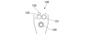
- FIG. 2 is a schematic diagram showing a pin-roll type distribution roll arranged below the chopper.
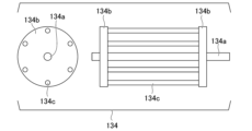
- FIG. 3 is a schematic diagram of a cage-type dispersing roll.
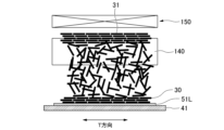
- FIG. 4 is a schematic diagram of the carbon fiber mat stacking portion and its vicinity as viewed from the conveying direction of the belt conveyor.
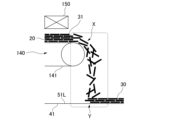
- FIG. 5 is a schematic view of the carbon fiber mat depositing portion and its neighborhood viewed from a direction orthogonal to the conveying direction of the belt conveyor.
- thermosetting resin paste to each surface of the first carrier film and the second carrier film.
- the thermosetting resin paste of the first carrier film is applied by dropping a plurality of short carbon fiber bundles on the first carrier film from the discharge end of the belt conveyor after being conveyed by the belt conveyor. depositing a carbon fiber mat on the surface.
- the second carrier film is laminated to the first carrier film with the carbon fiber mat sandwiched therebetween so that the surfaces coated with the thermosetting resin paste face each other to form a laminate. to do.
- impregnating the carbon fiber mat with the thermosetting resin paste by pressing the laminate;
- FIG. 1 shows a conceptual diagram of a CF-SMC manufacturing apparatus that can be preferably used when manufacturing CF-SMC using the manufacturing method according to the embodiment.
- the CF-SMC manufacturing apparatus 100 has a first coating machine 110, a second coating machine 120, a chopper 130, a belt conveyor 140, a heater 150 and an impregnator 160.
- the first coating machine 110 is used to apply the first resin paste 51 to the first carrier film 41 to form the first resin paste layer 51L on one surface of the first carrier film 41 .
- the second coating machine 120 is used to apply the second resin paste 52 to the second carrier film 42 to form the second resin paste layer 52L on one surface of the second carrier film 42 .
- the chopper 130 is of a type that is also used in conventional CF-SMC manufacturing equipment, and includes a cutter roll 131 , a receiving roll (rubber roll) 132 and a guide roll 133 .
- the rotating shafts of the cutter roll 131 , the receiving roll 132 and the guide roll 133 are all parallel to the T direction of the belt conveyor 140 .
- the T direction is the width direction of the conveying path of the belt conveyor 140, that is, the width direction of the conveying belt 141 that constitutes the conveying path, and is generally horizontal.
- the chopper 130 is arranged above the conveying path of the belt conveyor 140 .
- a dispersing roll 134 for dispersing the short carbon fiber bundles 20 (chopped carbon fiber bundles) falling from the chopper 130 may be arranged below the chopper.
- the rotation axis of the distribution roll 134 is parallel to the T direction of the belt conveyor 140 .
- the structure and number of distribution rolls 134 are not limited to those shown.
- the distribution roll 134 shown in FIG. 2 is of the pin roll type, it may be of the cage type shown in FIG.
- the pin roll type distribution roll has a cylinder and a plurality of pins arranged on the peripheral surface of the cylinder.
- the 3 has a structure in which a plurality of wires or rods 134c are bridged between a pair of discs 134b sharing a rotating shaft 134a.
- the number of distribution rolls is not limited to one, and may be two or more.
- the distribution roll is generally rigid and preferably made of metal (including alloys).
- a portion of the short carbon fiber bundles 20 is split into smaller bundle size carbon fiber bundles by contact with the distribution roll 134 . It is well known to those skilled in the art that the smaller the bundle size of short carbon fiber bundles contained in CF-SMC, the higher the strength of CFRP products molded from CF-SMC. By bundle size is meant the number of carbon fiber filaments per bundle.
- the short carbon fiber bundles 20 fall onto the conveying path of the belt conveyor 140 below the chopper 130 and are conveyed by the conveying belt 141 toward its discharge end.
- a discharge end of the belt conveyor 140 is arranged above the running path of the first carrier film 41 .
- the T direction of the belt conveyor 140 and the width direction of the first carrier film 41 running on the running path are parallel to each other.
- the running direction of the first carrier film 41 is horizontal below the discharge end of the belt conveyor 140 .
- the upper surface of the first carrier film 41 is preferably kept horizontal.
- a bonding machine 170 is arranged to gradually bring the first carrier film 41 and the second carrier film 42 closer together and bond them together.
- the laminate 60 is formed by bonding the first carrier film 41 and the second carrier film 42 together by the bonding machine 170 .
- the first resin paste layer 51L, the carbon fiber mat 30, and the second resin paste layer 52L are sandwiched between the first carrier film 41 and the second carrier film .
- the impregnation machine 160 is equipped with two upper and lower belt conveyors in order to sandwich and convey the laminate 60 from above and below with two conveyor belts, and also has rolls for sandwiching and pressurizing the laminate 60 together with the conveyor belts. ing.
- the heater 150 heats the short carbon fiber bundles 20 conveyed by the conveyor belt 141 of the belt conveyor 140 .
- the heater is arranged above the conveying path to heat the conveyed short carbon fiber bundles 20 from above.
- the short carbon fiber bundles 20 to be conveyed may be heated from above and below by being arranged above and below the conveying path.
- a heating method of the heater 150 is not particularly limited, but a hot air heater, an infrared heater, and the like are exemplified. Heaters 150 having different heating methods may be used together. For example, as the heater 150, a hot air heater and an infrared heater can be used together and arranged appropriately.
- the conveying belt 141 of the belt conveyor 140 When the conveying belt 141 of the belt conveyor 140 has a mesh structure, the short carbon fiber bundles 20 on the conveying belt can be directly heated from below the conveying path by a heater. The carbon fiber hank can be sucked onto the conveyor belt.
- the conveying belt 141 When the short carbon fiber bundles on the conveying path are heated by the heater arranged below the conveying path, the conveying belt 141 preferably has a mesh structure, but it is not essential.
- the transfer belt may be heated by a heater, and the short carbon fiber bundles may be heated by contact heat transfer from the transfer belt.
- Method for producing CF-SMC The procedure for producing CF-SMC using the production method according to the embodiment is described in 1. above.
- An example of using the CF-SMC manufacturing apparatus described in 1. is as follows. First, a long carbon fiber bundle 10 is pulled out from a fiber package prepared in advance. The long carbon fiber bundles 10 may be drawn outside from a bobbin package attached to a creel, or may be drawn inside from a package from which the bobbins have been removed. The long carbon fiber bundle 10 may be partially split into a plurality of sub-bundles in advance.
- a plurality of long carbon fiber bundles 10 are arranged parallel to each other and supplied to a chopper 130 .
- the chopper 130 cuts the long carbon fiber bundle 10 into a predetermined length to form the short carbon fiber bundle 20 .
- the predetermined length is preferably in the range of 10-60 mm, typically 0.5 inches (about 1.3 cm), 1 inch (about 2.5 cm), 2 inches (about 5.1 cm), etc. can be, but is not limited to.
- the short carbon fiber bundles 20 fall onto the conveyor belt 141 of the belt conveyor 140 passing below the chopper 130 and are conveyed toward the discharge end of the belt conveyor 140 .
- the short carbon fiber bundles 20 are heated by the heater 150 while being conveyed by the belt conveyor 140 .
- the temperature of the heated short carbon fiber bundles 20 may be 40°C or higher and lower than 120°C, may be 50°C or higher and lower than 110°C, or may be 60°C or higher and lower than 100°C.
- the above upper and lower limits can be arbitrarily combined to form a preferred temperature range.
- the temperature of the short carbon fiber bundles 20 dropped onto the belt conveyor 140 and heated can be measured with, for example, a thermocouple or a radiation thermometer.
- the temperature of the short carbon fiber bundles 20 can be controlled by the output of the heater 150, the heating time, and the density of the short carbon fiber bundles 20 on the belt conveyor 140.
- the heating time is the time required for each short carbon fiber bundle 20 to pass through the area heated by the heater 150, and is determined by the length of the area along the conveying direction of the belt conveyor and the conveying speed. When the space in which the belt conveyor 140 can be installed is narrow, a sufficient heating time can be ensured even if the conveying path is short by lowering the conveying speed.
- a mat temporary mat in which the short carbon fiber bundles 20 are stacked on the transport belt 141. 31 is deposited.
- the running speed of the conveyor belt 141 is equal to or less than the running speed of the first carrier film 41
- the thickness of the mat 31 is equal to or greater than the thickness of the carbon fiber mat 30 deposited on the first carrier film 41 .
- a suction nozzle is installed so that the lower side of the conveying path is decompressed, and the mat 31 is made to stick to the conveying belt 141, thereby preventing the short carbon fiber bundles from flying around while allowing the heater wire to move along the conveying path. may be placed above the mat to blow hot air onto the mat from above.
- the short carbon fiber bundles 20 contained in the mat are brought into close contact with each other, so that the contact thermal resistance between the short carbon fiber bundles is reduced and the heating of the entire mat 31 is promoted. . Therefore, even when the mat 31 is heated by the infrared heater, it is useful to cause the mat 31 to stick to the conveying belt 141 by suction.
- the infrared heater can be arranged below the conveying path even in a mode in which the lower side of the conveying path is decompressed.
- the short carbon fiber bundles 20 can be sufficiently heated with the heater 150 installed only above.
- the heater 150 may be an infrared heater, a hot air heater, or both.
- a hot air heater it is preferable to use a mesh belt as the conveying belt 141 and blow hot air from the upper surface side of the conveying belt.
- the transport belt 141 is a mesh belt, and the lower side of the transport path is decompressed to cause the short carbon fiber bundles 20 to stick to the transport belt 141, thereby preventing the short carbon fiber bundles from flying. good too.
- the short carbon fiber bundles 20 fall from the discharge end of the belt conveyor 140, and the carbon fiber mat 30 made of the short carbon fiber bundles 20 is placed on the first carrier film 41 running below the discharge end. accumulate.
- a space (inside the dashed line in FIG. 5) including at least the discharge end X of the belt conveyor 140 and the carbon fiber mat deposition portion Y where the carbon fiber mat 30 is deposited on the first carrier film 41. is maintained at a higher temperature than its surroundings. By doing so, it is possible to prevent the temperature of the short carbon fiber bundles 20 from being cooled too much during the fall.
- This space may be extended to include the heater 150 and the area where the short carbon fiber bundles 20 on the belt conveyor 140 are heated by the heater 150 .
- the first resin paste 51 is applied to one side of the first carrier film 41 pulled out from the roll using the first coating machine 110 .
- the first resin paste 51 is a thermosetting resin composition, and its base resin is not limited, but may be, for example, vinyl ester resin (also called epoxy acrylate resin), unsaturated polyester resin, epoxy resin, polyimide resin, Maleimide resin or phenolic resin.
- a mixed resin of a vinyl ester resin and an unsaturated polyester resin may be used as the base resin.
- the first resin paste 51 contains a curing agent and, if necessary, a polymerization inhibitor, a thickener, a reactive diluent, a low shrinkage agent, a flame retardant, an antibacterial agent, and the like.
- the viscosity of the first resin paste 51 may be 0.3 to 20 Pa ⁇ s at 25°C. A resin paste having such viscosity characteristics can be used even at room temperature, but by heating to lower the viscosity, it becomes easier to penetrate into the carbon fiber mat. In another example, the viscosity of the first resin paste 51 may be 5-20 Pa ⁇ s at a certain temperature in the range of 40-80°C. A resin paste having such viscosity characteristics can be used for impregnating the carbon fiber mat by heating, even if it is difficult to penetrate the carbon fiber mat at room temperature.
- a second coating machine 120 is used to apply a second resin paste 52 made of a thermosetting resin composition having the same composition as the first resin paste 51 to one side of the second carrier film 42 .
- the second carrier film 42 is laminated on the first carrier film 41 with the carbon fiber mat 30 placed thereon by the laminator 170, with the surface on which the second resin paste layer 52L is formed facing down.
- the laminate 60 thus formed is pressurized by the impregnator 160 to impregnate the carbon fiber mat 30 with the first resin paste 51 and the second resin paste 52 to form a resin-impregnated carbon fiber mat.
- the temperature of the short carbon fiber bundles 20 dropped onto the first resin paste layer 51L may be 40°C or higher and lower than 120°C, may be 50°C or higher and lower than 110°C, or may be 60°C or higher and lower than 100°C.
- the above upper and lower limits can be arbitrarily combined to form a preferred temperature range.
- the temperature can be measured using non-contact measurement methods such as radiation thermometers.
- the first resin paste layer 51L and the second resin paste layer 52L may be heated by a heater (not shown) before they come into contact with the short carbon fiber bundles 20.
- a heater not shown
- the temperature drop of the first resin paste 51 and the second resin paste 52 due to contact with the short carbon fiber bundles 20 and the accompanying increase in viscosity are prevented or suppressed by heating the short carbon fiber bundles 20 by the heater 150. be.
- the resin-impregnated carbon fiber mat is wound around a bobbin while being sandwiched between the first carrier film 41 and the second carrier film 42 .
- the resin-impregnated carbon fiber mat wound on a bobbin is thickened as necessary and shipped as CF-SMC.
- the resin impregnated carbon fiber mat may be folded and stored in a container instead of being wound on a bobbin.
- the first resin paste 51 and the second resin paste 52 respectively stored in the first coating machine 110 and the second coating machine 120 are heated or kept warm, and the laminate 60 conveyed by the impregnation machine 160 is Heating or keeping warm can be appropriately performed as needed. Heating or keeping the temperature of the first resin paste 51 and the second resin paste 52 before they are supplied to the coating machine can also be performed by an appropriate method as necessary.
- the laminate 60 (the resin-impregnated carbon fiber mat sandwiched between the first carrier film 41 and the second carrier film 42) may be cooled before being wound onto a bobbin or folded and stored in a container. .
- the initiation of the curing reaction of the first resin paste and the second resin paste which are thermosetting resin compositions, can be prevented. Since the viscosity of the first resin paste and the second resin paste present in the gap between them increases, it becomes difficult to squeeze them out of the carbon fiber mat 30 .
- Cooling may be performed until the temperature of the laminate 60 drops to room temperature, but is not limited, and may be performed to the extent that the above purpose can be achieved. Examples of the cooling method include, but are not limited to, forced air cooling using a fan and contact with a cooling roll. Forced air cooling and cooling rolls may be used in combination.
- the long carbon fiber bundles 10 fed toward the chopper 130 may additionally be heated. However, if the sizing agent is heated until it softens, the short carbon fiber bundles 20 stick to the rubber roll of the chopper 130, so it is necessary to pay attention to the temperature of the short carbon fiber bundles 20 after heating.
- a method of cutting the long carbon fiber bundles into short carbon fiber bundles instead of cutting the long carbon fiber bundles into short carbon fiber bundles by cutting the long carbon fiber bundles with a chopper provided in the CF-SMC manufacturing apparatus, a method of cutting the long carbon fiber bundles in a separate process in advance or other methods. The short carbon fiber bundles made by the method may be supplied onto the conveying path of the belt conveyor.
- conveying means other than a belt conveyor may be used to convey a plurality of short carbon fiber bundles from where they are produced and then drop them onto the first carrier film.
- transport means include a container capable of storing short carbon fiber bundles and equipped with a heater for heating the stored short carbon fibers, and a transporter for transporting the container. .
- this modified embodiment has in common with the embodiment using a belt conveyor as the transportation means.
- thermosetting paste that does not have fluidity at room temperature and has a viscosity of preferably 20 Pa s or less is obtained only by heating.
- a flexible resin composition can be used.
- the thermosetting resin composition instead of applying the thermosetting resin composition to the first carrier film and the second carrier film using the first coating machine and the second coating machine, the first carrier film and the second carrier film are separately applied in advance. It can be applied to the film.
- Embodiments of the present invention include, but are not limited to, the following.
- a thermosetting resin paste is applied to each surface of the first carrier film and the second carrier film, and after conveying a plurality of short carbon fiber bundles by a belt conveyor, from the discharge end of the belt conveyor depositing a carbon fiber mat on the surface of the first carrier film coated with the thermosetting resin paste by dropping it onto the first carrier film;
- a laminate is formed by pasting the mat to the first carrier film so that the surfaces coated with the thermosetting resin paste face each other with a mat interposed therebetween, and pressing the laminate by pressing the laminate.
- a method for producing a sheet prepreg comprising: impregnating a carbon fiber mat with the thermosetting resin paste; and heating the plurality of short carbon fiber bundles with a heater while being conveyed by the belt conveyor.
- [Embodiment 2] A space including at least the discharge end of the belt conveyor and a carbon fiber mat depositing portion where the carbon fiber mat is deposited on the first carrier film is maintained at a higher temperature than the surroundings. 2.
- Embodiment 4 The method according to Embodiment 3, wherein the plurality of short carbon fiber bundles are dispersed by a dispersion roll arranged below the chopper before dropping onto the conveying path.
- Embodiment 5. The method of any of Embodiments 1-4, wherein the heater comprises a hot air heater and/or an infrared heater.
- the heaters are arranged respectively above and below the transport belt of the belt conveyor.
- the conveyor belt of the belt conveyor has a mesh structure.
- Embodiment 8 The method according to Embodiment 7, comprising attracting the plurality of short carbon fiber bundles to the conveyor belt by suction.
- Embodiment 9 The method according to any one of Embodiments 1 to 8, wherein the running speed of the transport belt of the belt conveyor is higher than the running speed of the first carrier film.
- Embodiment 10 The method of any of Embodiments 1-4, comprising depositing the temporary mat of carbon fiber bundles on a conveyor belt of the belt conveyor.
- Embodiment 11 The method of embodiment 10, wherein the thickness of the temporary mat is equal to or greater than the thickness of the carbon fiber mat.
- Embodiment 12 Embodiment 10 or 11, wherein the conveying belt of the belt conveyor has a mesh structure, and hot air is blown onto the temporary mat from both the upper side and the lower side of the conveying belt.
- method pertaining to [Embodiment 13] The method according to embodiment 12, wherein part of the hot air flows through the interior of the temporary mat in a direction crossing the thickness direction of the temporary mat.
- Embodiment 14 A method according to embodiment 10 or 11, wherein the conveyor belt of the belt conveyor has a mesh structure and the temporary mat is attracted to the conveyor belt by suction.
- Embodiment 15 The method of any of Embodiments 1-14, further comprising heating the thermosetting resin paste prior to depositing the carbon fiber mat.
- Embodiment 16 The method according to any one of Embodiments 1 to 15, wherein the length of the short carbon fiber bundles is within the range of 10 to 60 mm.
- Embodiment 17 Prepare a first carrier film and a second carrier film each having a layer of a thermosetting resin composition preliminarily provided on the surface thereof, and convey a plurality of short carbon fiber bundles using a conveying means.
- a method for manufacturing a sheet prepreg comprising: [Embodiment 18] The method according to Embodiment 17, wherein the plurality of short carbon fiber bundles are produced by cutting long carbon fibers with a chopper. Embodiment 19.
- said conveying means is a belt conveyor.
- a space containing at least the discharge end of the belt conveyor and the carbon fiber mat depositing portion where the carbon fiber mat is deposited on the first carrier film is maintained at a higher temperature than the surroundings. 20.
- Embodiment 22 The method according to Embodiment 21, wherein the plurality of short carbon fiber bundles are dispersed by a dispersion roll arranged below the chopper before dropping onto the conveying path.
- Embodiment 23 The method of any of Embodiments 19-22, wherein the heater comprises a hot air heater and/or an infrared heater.
- Embodiment 24 The method according to any one of embodiments 19 to 23, wherein the heaters are arranged respectively above and below the transport belt of the belt conveyor.
- Embodiment 25 The method of any of Embodiments 19-24, wherein the conveyor belt of the belt conveyor has a mesh structure.
- Embodiment 26 The method of embodiment 25, comprising attracting the plurality of short carbon fiber bundles to the conveyor belt by suction.
- Embodiment 27 The method according to any one of Embodiments 19 to 26, wherein the running speed of the transport belt of the belt conveyor is greater than the running speed of the first carrier film.
- Embodiment 28 The method of any of embodiments 19-22, comprising depositing the temporary mat of carbon fiber bundles on a conveyor belt of the belt conveyor.
- Embodiment 29 The method of embodiment 28, wherein the thickness of the temporary mat is equal to or greater than the thickness of the carbon fiber mat.
- Embodiment 30 Embodiment 28 or 29, wherein the conveying belt of the belt conveyor has a mesh structure, and hot air is blown onto the temporary mat from both the upper side and the lower side of the conveying belt.
- method pertaining to [Embodiment 31] A method according to Embodiment 30, wherein a portion of the hot air flows through the interior of the temporary mat in a direction crossing the thickness direction of the temporary mat.
- Embodiment 32 A method according to embodiment 28 or 29, wherein the conveying belt of the belt conveyor has a mesh structure and the temporary mat is attracted to the conveying belt by suction.
- Embodiment 33 The method of any of Embodiments 17-32, further comprising heating said thermosetting resin composition prior to depositing said carbon fiber mat.
- the short carbon fiber bundles have a length in the range of 10-60 mm.
- the impregnation of the carbon fiber mat is promoted by using the method according to the embodiment, the impregnation time required to prevent impregnation failure is shortened, and the line speed of the CF-SMC production line can be increased. becomes.
- the viscosity of the matrix resin can be reduced by heating. Therefore, it is possible to use a thermosetting resin composition with a high room temperature viscosity, which was conventionally not suitable for CF-SMC, as the matrix resin. It becomes possible.
- CFRP carbon fiber reinforced plastic
- CFRP products that can be manufactured using CF-SMC are diverse, including manned aircraft, unmanned aircraft, parts used in various transportation equipment including automobiles and ships, sporting goods, leisure goods, and the like.
Landscapes
- Engineering & Computer Science (AREA)
- Life Sciences & Earth Sciences (AREA)
- Wood Science & Technology (AREA)
- Mechanical Engineering (AREA)
- Reinforced Plastic Materials (AREA)
- Application Of Or Painting With Fluid Materials (AREA)
Abstract
炭素繊維マットの含浸不良の発生防止に寄与しうる、CF-SMC製造技術の改良を提供する。本発明のシートプリプレグの製造方法の一態様は、第一及び第二キャリアフィルムの表面に熱硬化性樹脂ペーストを塗布すること、複数の短尺炭素繊維束(20)をベルトコンベア(140)で搬送し、その排出端から第一キャリアフィルム(41)上に落下させ、熱硬化性樹脂ペーストが塗布された面上に炭素繊維マット(30)を堆積させること、第二キャリアフィルム(42)を、炭素繊維マット(30)を間に挟んで、熱硬化性樹脂ペーストが塗布された表面同士が互いに向き合うように第一キャリアフィルム(41)に貼り合わせて積層体(60)を形成すること、前記積層体(60)を加圧して炭素繊維マット(30)を熱硬化性樹脂ペーストで含浸させること、複数の短尺炭素繊維束(20)をベルトコンベア(140)で搬送する間にヒーター(150)で加熱することを含む。
Description
本発明は、主として、シートプリプレグの製造方法、とりわけ、炭素繊維を用いたシートプリプレグの製造方法に関する。
本願は、2021年12月1日に日本出願された特願2021-195690号に基づき優先権を主張し、その内容をここに援用する。
本願は、2021年12月1日に日本出願された特願2021-195690号に基づき優先権を主張し、その内容をここに援用する。
炭素繊維強化プラスチック(CFRP)は、有人航空機、無人航空機、自動車および船舶を含む各種の輸送機器の部品、スポーツ用品、レジャー用品などに適した、軽量かつ力学特性に優れた材料であり、近年その重要度はますます高くなっている。
CFRP製品を効率的に製造する方法のひとつに、炭素繊維シートモールディングコンパウンド(CF-SMC)のようなシートプリプレグをプレス成形用の中間材料として用いる方法がある。
CFRP製品を効率的に製造する方法のひとつに、炭素繊維シートモールディングコンパウンド(CF-SMC)のようなシートプリプレグをプレス成形用の中間材料として用いる方法がある。
CF-SMCの製造工程では、長尺炭素繊維束をチョッパーで切断して短尺炭素繊維束とし、走行するキャリアフィルム上に落下させることによって、炭素繊維マットが形成された後、キャリアフィルムに予め塗布されていたマトリックス樹脂で炭素繊維マットが含浸される。CF-SMCの製造において、炭素繊維マットの含浸不良を発生させないために、含浸前にマトリックス樹脂を加熱して低粘度化することが提案されている(特許文献1)。
特許文献1に開示された方法では、含浸前に炭素繊維束も遠赤外線ヒーターで加熱されているが、そのタイミングは、マトリックス樹脂が塗布されたキャリアフィルム上に炭素繊維束が散布された後である。キャリアフィルム上に落下させる前に炭素繊維束を加熱することや、そのための手段は、特許文献1に開示されていない。
マトリックス樹脂を予め加熱したとしても、それと同時に、キャリアフィルム上に落下させる短尺炭素繊維束の温度を上げないと、含浸不良の防止効果は十分に得られない。なぜなら、マトリックス樹脂の温度が、その上に炭素繊維マットを堆積させることによって下がってしまうからである。
チョッパーで連続炭素繊維束を切断することにより生じる短尺炭素繊維束を直接キャリアフィルム上に落下させる場合、落下時間が短いために、落下中に短尺炭素繊維束を加熱することにより温度を十分に高めるのは困難である。
チョッパーで連続炭素繊維束を切断することにより生じる短尺炭素繊維束を直接キャリアフィルム上に落下させる場合、落下時間が短いために、落下中に短尺炭素繊維束を加熱することにより温度を十分に高めるのは困難である。
本発明の主たる目的は、炭素繊維マットの含浸不良の発生防止に寄与し得る、CF-SMC製造技術の改良を提供することにある。
本明細書中には、本発明の各実施形態により解決され得る課題が明示的に又は黙示的に開示されている場合がある。
本明細書中には、本発明の各実施形態により解決され得る課題が明示的に又は黙示的に開示されている場合がある。
本発明のシートプリプレグの製造方法の一態様は以下を含む。
第一キャリアフィルムと第二キャリアフィルムのそれぞれの表面に熱硬化性樹脂ペーストを塗布することと、複数の短尺炭素繊維束をベルトコンベアで搬送した後に前記ベルトコンベアの排出端から前記第一キャリアフィルム上に落下させることにより、前記第一キャリアフィルムの前記熱硬化性樹脂ペーストが塗布された面上に炭素繊維マットを堆積させることと、前記第二キャリアフィルムを、前記炭素繊維マットを間に挟んで、前記熱硬化性樹脂ペーストが塗布された表面同士が互いに向き合うように前記第一キャリアフィルムに貼り合わせて積層体を形成することと、前記積層体を加圧することにより前記炭素繊維マットを前記熱硬化性樹脂ペーストで含浸させることと、前記複数の短尺炭素繊維束を前記ベルトコンベアで搬送する間にヒーターで加熱することと、を含むシートプリプレグの製造方法。
また、本発明のシートプリプレグの製造方法の別の一態様は以下を含む。
それぞれ表面に熱硬化性樹脂組成物の層が予め設けられた第一キャリアフィルムおよび第二キャリアフィルムを準備することと、複数の短尺炭素繊維束を、搬送手段を用いて搬送した後に、前記第一キャリアフィルム上に落下させることにより、前記第一キャリアフィルムの前記熱硬化性樹脂組成物の層が設けられた面上に炭素繊維マットを堆積させることと、前記第二キャリアフィルムを、前記炭素繊維マットを間に挟んで、前記熱硬化性樹脂組成物の層が設けられた表面同士が互いに向き合うように前記第一キャリアフィルムに貼り合わせて積層体を形成することと、前記積層体を加圧することにより前記炭素繊維マットを前記熱硬化性樹脂組成物で含浸させることと、前記複数の短尺炭素繊維束を前記搬送手段で搬送する間にヒーターで加熱することと、を含むシートプリプレグの製造方法。
本発明によれば、炭素繊維マットの含浸不良の発生防止に寄与し得る、CF-SMC製造技術の改良が提供される。
本発明の一実施態様は、次の(i)~(v)を含むCF-SMCの製造方法に関する。
(i)第一キャリアフィルムと第二キャリアフィルムのそれぞれの表面に熱硬化性樹脂ペーストを塗布すること。
(ii)複数の短尺炭素繊維束をベルトコンベアで搬送した後に前記ベルトコンベアの排出端から前記第一キャリアフィルム上に落下させることにより、前記第一キャリアフィルムの前記熱硬化性樹脂ペーストが塗布された面上に炭素繊維マットを堆積させること。
(iii)前記第二キャリアフィルムを、前記炭素繊維マットを間に挟んで、前記熱硬化性樹脂ペーストが塗布された表面同士が互いに向き合うように前記第一キャリアフィルムに貼り合わせて積層体を形成すること。
(iv)前記積層体を加圧することにより前記炭素繊維マットを前記熱硬化性樹脂ペーストで含浸させること。
(v)前記複数の短尺炭素繊維束を前記ベルトコンベアで搬送する間にヒーターで加熱すること。
1.CF-SMC製造装置
実施形態に係る上記の製造方法を用いてCF-SMCを製造するときに好ましく用い得るCF-SMC製造装置の概念図を図1に示す。
図1を参照すると、CF-SMC製造装置100は、第一塗工機110、第二塗工機120、チョッパー130、ベルトコンベア140、ヒーター150及び含浸機160を有する。
第一塗工機110は、第一キャリアフィルム41に第一樹脂ペースト51を塗布して、第一キャリアフィルム41の一方の表面に第一樹脂ペースト層51Lを形成するために用いられる。
第二塗工機120は、第二キャリアフィルム42に第二樹脂ペースト52を塗布して、第二キャリアフィルム42の一方の表面に第二樹脂ペースト層52Lを形成するために用いられる。
チョッパー130は、従来のCF-SMC製造装置でも使用されているタイプのものであり、カッターロール131、受けロール(ゴムロール)132、及びガイドロール133を備える。
カッターロール131、受けロール132及びガイドロール133の回転軸は、いずれもベルトコンベア140のT方向に平行である。T方向とは、ベルトコンベア140の搬送路の幅方向、すなわち、搬送路を構成する搬送ベルト141の幅方向であり、通常は水平とされる。
チョッパー130は、ベルトコンベア140の搬送路の上方に配置されている。
カッターロール131、受けロール132及びガイドロール133の回転軸は、いずれもベルトコンベア140のT方向に平行である。T方向とは、ベルトコンベア140の搬送路の幅方向、すなわち、搬送路を構成する搬送ベルト141の幅方向であり、通常は水平とされる。
チョッパー130は、ベルトコンベア140の搬送路の上方に配置されている。
一態様では、図2に示すように、チョッパー130から落下する短尺炭素繊維束20(チョップド炭素繊維束)を分散させるための分散ロール134を、チョッパーの下方に配置してもよい。分散ロール134の回転軸は、ベルトコンベア140のT方向に平行である。
分散ロール134の構造及び数は図示するものに限定されない。図2に示す分散ロール134はピンロール型であるが、図3に示すかご型であってもよい。
図示しないが、ピンロール型の分散ロールは、シリンダーと、前記シリンダーの周面に配置された複数のピンとを有している。図3に示すかご型の分散ロール(ケージロール)134は、回転軸134aを共有する一対の円盤134bの間に、複数のワイヤー又はロッド134cが架け渡された構造を有している。
分散ロールの数は1個に限定されず、2個以上であってもよい。分散ロールは、通常、剛体であり、好ましくは金属(合金を含む)で形成される。
分散ロール134の構造及び数は図示するものに限定されない。図2に示す分散ロール134はピンロール型であるが、図3に示すかご型であってもよい。
図示しないが、ピンロール型の分散ロールは、シリンダーと、前記シリンダーの周面に配置された複数のピンとを有している。図3に示すかご型の分散ロール(ケージロール)134は、回転軸134aを共有する一対の円盤134bの間に、複数のワイヤー又はロッド134cが架け渡された構造を有している。
分散ロールの数は1個に限定されず、2個以上であってもよい。分散ロールは、通常、剛体であり、好ましくは金属(合金を含む)で形成される。
分散ロール134と接触することで、一部の短尺炭素繊維束20はより小さな束サイズの炭素繊維束に分割される。CF-SMCに含まれる短尺炭素繊維束の束サイズが小さい程、CF-SMCから成形されるCFRP製品の強度が高くなることは、当業者にはよく知られている。束サイズとは、束当たりの炭素繊維フィラメントの本数を意味する。
短尺炭素繊維束20はチョッパー130の下方にあるベルトコンベア140の搬送路上に落下し、搬送ベルト141によってその排出端に向かって搬送される。
ベルトコンベア140の排出端は、第一キャリアフィルム41の走行路の上方に配置されている。ベルトコンベア140のT方向と走行路上を走行する第一キャリアフィルム41の幅方向は互いに平行である。
ベルトコンベア140の排出端は、第一キャリアフィルム41の走行路の上方に配置されている。ベルトコンベア140のT方向と走行路上を走行する第一キャリアフィルム41の幅方向は互いに平行である。
ベルトコンベア140の排出端の下方において、第一キャリアフィルム41の走行方向は水平であることが好ましい。換言すれば、ベルトコンベア140の排出端の下方において、第一キャリアフィルム41の上面は、好ましくは水平に維持される。
含浸機160の上流側には、第一キャリアフィルム41と第二キャリアフィルム42とを徐々に近づけて貼り合わせる貼り合わせ機170が配置されている。貼り合わせ機170によって、第一キャリアフィルム41と第二キャリアフィルム42とが貼り合わされて、積層体60が形成される。積層体60においては、第一キャリアフィルム41と第二キャリアフィルム42の間に、第一樹脂ペースト層51L、炭素繊維マット30及び第二樹脂ペースト層52Lが挟まれる。この積層体60を、2つの搬送ベルトで上下から挟んで搬送するために、含浸機160は上下2つのベルト搬送機を備えるとともに、積層体60を搬送ベルトごと挟んで加圧するためのロールを備えている。
含浸機160の上流側には、第一キャリアフィルム41と第二キャリアフィルム42とを徐々に近づけて貼り合わせる貼り合わせ機170が配置されている。貼り合わせ機170によって、第一キャリアフィルム41と第二キャリアフィルム42とが貼り合わされて、積層体60が形成される。積層体60においては、第一キャリアフィルム41と第二キャリアフィルム42の間に、第一樹脂ペースト層51L、炭素繊維マット30及び第二樹脂ペースト層52Lが挟まれる。この積層体60を、2つの搬送ベルトで上下から挟んで搬送するために、含浸機160は上下2つのベルト搬送機を備えるとともに、積層体60を搬送ベルトごと挟んで加圧するためのロールを備えている。
ヒーター150は、ベルトコンベア140の搬送ベルト141によって搬送される短尺炭素繊維束20を加熱する。図1ではヒーターを搬送路の上方に配置して、搬送される短尺炭素繊維束20を上から加熱しているが、搬送路の下方に配置して、搬送される短尺炭素繊維束20を下から加熱してもよいし、搬送路の上方及び下方に配置して、搬送される短尺炭素繊維束20を上下から加熱してもよい。
ヒーター150の加熱方式は特に限定されないが、熱風ヒーター、赤外線ヒーターなどが例示される。加熱方式の異なるヒーター150を併用してもよい。例えば、ヒーター150として、熱風ヒーター及び赤外線ヒーターを併用し、適宜配置することができる。
ヒーター150の加熱方式は特に限定されないが、熱風ヒーター、赤外線ヒーターなどが例示される。加熱方式の異なるヒーター150を併用してもよい。例えば、ヒーター150として、熱風ヒーター及び赤外線ヒーターを併用し、適宜配置することができる。
ベルトコンベア140の搬送ベルト141がメッシュ構造であると、搬送ベルト上の短尺炭素繊維束20を搬送路の下方からヒーターで直接的に加熱することができる他、搬送ベルトの下方を減圧して短尺炭素繊維束を搬送ベルトに吸い付かせることができる。
搬送路の下方に配置したヒーターで搬送路上の短尺炭素繊維束を加熱するとき、搬送ベルト141はメッシュ構造を有することが好ましいが、必須ではない。搬送ベルトをヒーターで加熱し、搬送ベルトからの接触伝熱によって短尺炭素繊維束を加熱してもよい。
搬送路の下方に配置したヒーターで搬送路上の短尺炭素繊維束を加熱するとき、搬送ベルト141はメッシュ構造を有することが好ましいが、必須ではない。搬送ベルトをヒーターで加熱し、搬送ベルトからの接触伝熱によって短尺炭素繊維束を加熱してもよい。
2.CF-SMCの製造方法
実施形態に係る製造方法を用いたCF-SMCの製造手順を、前記1.で説明したCF-SMC製造装置を用いる場合を例にして説明すると次の通りである。
まず、予め準備された繊維パッケージから、長尺炭素繊維束10が引き出される。長尺炭素繊維束10は、クリールに取り付けられたボビンパッケージから外取りで引き出されてもよいし、あるいは、ボビンが抜き取られたパッケージから内取りで引き出されてもよい。
長尺炭素繊維束10は、予め、部分的に複数のサブ束にスプリットされていてもよい。
実施形態に係る製造方法を用いたCF-SMCの製造手順を、前記1.で説明したCF-SMC製造装置を用いる場合を例にして説明すると次の通りである。
まず、予め準備された繊維パッケージから、長尺炭素繊維束10が引き出される。長尺炭素繊維束10は、クリールに取り付けられたボビンパッケージから外取りで引き出されてもよいし、あるいは、ボビンが抜き取られたパッケージから内取りで引き出されてもよい。
長尺炭素繊維束10は、予め、部分的に複数のサブ束にスプリットされていてもよい。
複数本の長尺炭素繊維束10が互いに平行となるように引き揃えられ、チョッパー130に供給される。
チョッパー130によって、長尺炭素繊維束10は所定長さに切断されて短尺炭素繊維束20となる。該所定長さは、好ましくは10~60mmの範囲内であり、典型的には0.5インチ(約1.3cm)、1インチ(約2.5cm)、2インチ(約5.1cm)などであり得るが、限定はされない。
チョッパー130によって、長尺炭素繊維束10は所定長さに切断されて短尺炭素繊維束20となる。該所定長さは、好ましくは10~60mmの範囲内であり、典型的には0.5インチ(約1.3cm)、1インチ(約2.5cm)、2インチ(約5.1cm)などであり得るが、限定はされない。
短尺炭素繊維束20は、チョッパー130の下方を通るベルトコンベア140の搬送ベルト141上に落下し、ベルトコンベア140の排出端に向かって搬送される。
ベルトコンベア140で搬送される間に、短尺炭素繊維束20はヒーター150によって加熱される。加熱された短尺炭素繊維束20の温度は40℃以上120℃未満であり得、50℃以上110℃未満であり得、60℃以上100℃未満であり得る。例えば、40℃以上50℃未満、50℃以上60℃未満、60℃以上70℃未満、70℃以上80℃未満、80℃以上90℃未満、90℃以上100℃未満、100℃以上110℃未満、110℃以上120℃未満などであり得る。上記の上限及び下限は任意に組み合わせて好ましい温度範囲とすることができる。ベルトコンベア140上に落下し、加熱された短尺炭素繊維束20の温度は、例えば熱電対や放射温度計で測定することができる。
ベルトコンベア140で搬送される間に、短尺炭素繊維束20はヒーター150によって加熱される。加熱された短尺炭素繊維束20の温度は40℃以上120℃未満であり得、50℃以上110℃未満であり得、60℃以上100℃未満であり得る。例えば、40℃以上50℃未満、50℃以上60℃未満、60℃以上70℃未満、70℃以上80℃未満、80℃以上90℃未満、90℃以上100℃未満、100℃以上110℃未満、110℃以上120℃未満などであり得る。上記の上限及び下限は任意に組み合わせて好ましい温度範囲とすることができる。ベルトコンベア140上に落下し、加熱された短尺炭素繊維束20の温度は、例えば熱電対や放射温度計で測定することができる。
短尺炭素繊維束20の温度は、ヒーター150の出力、加熱時間及びベルトコンベア140上の短尺炭素繊維束20の密度により制御することができる。加熱時間は短尺炭素繊維束20のひとつひとつが、ヒーター150で加熱される領域を通過するのに要する時間であり、ベルトコンベアの搬送方向に沿った該領域の長さと搬送速度により定まる。
ベルトコンベア140を設置できるスペースが狭いときは、搬送速度を下げることで、搬送路が短くても加熱時間を十分に確保することができる。
ベルトコンベア140を設置できるスペースが狭いときは、搬送速度を下げることで、搬送路が短くても加熱時間を十分に確保することができる。
搬送ベルト141の走行速度が比較的遅く、例えば、第一キャリアフィルム41の走行速度と同等以下であるようなとき、搬送ベルト141上には短尺炭素繊維束20が積み重なったマット(一時的マット)31が堆積する。搬送ベルト141の走行速度が第一キャリアフィルム41の走行速度と同等以下のとき、マット31の厚さは、第一キャリアフィルム41上に堆積する炭素繊維マット30の厚さと同等以上となる。
マット31を加熱するときは、搬送ベルト141をメッシュ構造とし、搬送路の上下両方から熱風を弱く吹き付けるようにすると、マットの表面だけでなく内部までよく加熱することができる。熱風がマットの内部を、マットの厚さ方向と交わる方向に流れるからである。
代替例では、搬送路の下側が減圧されるように吸引ノズルを設置し、マット31を搬送ベルト141に吸い付かせることで、短尺炭素繊維束が舞うのを防止しつつ、ヒーター線を搬送路の上方に配置して、上方からマットに熱風を吹き付けてもよい。
マット31を加熱するときは、搬送ベルト141をメッシュ構造とし、搬送路の上下両方から熱風を弱く吹き付けるようにすると、マットの表面だけでなく内部までよく加熱することができる。熱風がマットの内部を、マットの厚さ方向と交わる方向に流れるからである。
代替例では、搬送路の下側が減圧されるように吸引ノズルを設置し、マット31を搬送ベルト141に吸い付かせることで、短尺炭素繊維束が舞うのを防止しつつ、ヒーター線を搬送路の上方に配置して、上方からマットに熱風を吹き付けてもよい。
マット31を搬送ベルト141に吸い付かせると、マットに含まれる短尺炭素繊維束20どうしが互いに密着するので、短尺炭素繊維束間の接触熱抵抗が低下し、マット31全体の加熱が促進される。従って、マット31を赤外線ヒーターで加熱する場合においても、吸引によってマット31を搬送ベルト141に吸い付かせることは有用である。
赤外線ヒーターは、搬送路の下側を減圧する態様においても、搬送路の下方に配置することが可能である。
赤外線ヒーターは、搬送路の下側を減圧する態様においても、搬送路の下方に配置することが可能である。
搬送ベルト141の走行速度を速くして、搬送ベルト上に短尺炭素繊維束20が厚く積もらないようにしたとき、とりわけ、短尺炭素繊維束20同士が互いに重ならないようにしたときは、搬送路の上方にのみ設置したヒーター150で短尺炭素繊維束20を十分に加熱することができる。この場合、ヒーター150は赤外線ヒーターでもよいし、熱風ヒーターであってもよいし、両者を併用してもよい。熱風ヒーターを用いる場合には、搬送ベルト141をメッシュベルトとして、搬送ベルトの上面側から熱風を吹き付けることが好ましい。
追加的又は代替的に、搬送ベルト141をメッシュベルトとし、搬送路の下側を減圧して短尺炭素繊維束20を搬送ベルト141に吸い付かせることによって、短尺炭素繊維束が舞わないようにしてもよい。
追加的又は代替的に、搬送ベルト141をメッシュベルトとし、搬送路の下側を減圧して短尺炭素繊維束20を搬送ベルト141に吸い付かせることによって、短尺炭素繊維束が舞わないようにしてもよい。
図4に示すように、短尺炭素繊維束20はベルトコンベア140の排出端から落下し、その排出端の下方を走行する第一キャリアフィルム41上に短尺炭素繊維束20からなる炭素繊維マット30が堆積する。
好適例においては、少なくともベルトコンベア140の排出端Xと、第一キャリアフィルム41上に炭素繊維マット30が堆積する部位である炭素繊維マット堆積部Yとを含む空間(図5の破線の内側)を、周囲よりも高温に保持する。そうすることで、落下中に短尺炭素繊維束20が冷却されて温度が下がり過ぎることを防止できる。
図5の破線の内側部分の空間を周囲よりも高温に維持する方法としては、前記空間を板やシートで囲うことで、可能な範囲で外気から遮断したうえ、その空間に温風を供給する方法が例示できる。
この空間を延長して、ヒーター150と、ベルトコンベア140上の短尺炭素繊維束20がヒーター150により加熱される領域も、この空間に含まれるようにしてもよい。
この空間を延長して、ヒーター150と、ベルトコンベア140上の短尺炭素繊維束20がヒーター150により加熱される領域も、この空間に含まれるようにしてもよい。
炭素繊維マット30を堆積させる前に、ロールから引き出された第一キャリアフィルム41の片面には、第一塗工機110を用いて第一樹脂ペースト51が塗布される。
第一樹脂ペースト51は熱硬化性樹脂組成物であり、そのベース樹脂は、限定するものではないが、例えばビニルエステル樹脂(エポキシアクリレート樹脂ともいう)、不飽和ポリエステル樹脂、エポキシ樹脂、ポリイミド樹脂、マレイミド樹脂又はフェノール樹脂である。ビニルエステル樹脂と不飽和ポリエステル樹脂の混合樹脂をベース樹脂としてもよい。第一樹脂ペースト51には、硬化剤が配合される他、必要に応じて、重合禁止剤、増粘剤、反応性希釈剤、低収縮剤、難燃剤、抗菌剤などが配合される。
第一樹脂ペースト51は熱硬化性樹脂組成物であり、そのベース樹脂は、限定するものではないが、例えばビニルエステル樹脂(エポキシアクリレート樹脂ともいう)、不飽和ポリエステル樹脂、エポキシ樹脂、ポリイミド樹脂、マレイミド樹脂又はフェノール樹脂である。ビニルエステル樹脂と不飽和ポリエステル樹脂の混合樹脂をベース樹脂としてもよい。第一樹脂ペースト51には、硬化剤が配合される他、必要に応じて、重合禁止剤、増粘剤、反応性希釈剤、低収縮剤、難燃剤、抗菌剤などが配合される。
一例において、第一樹脂ペースト51の粘度は、25℃において、0.3~20Pa・sであってもよい。かかる粘度特性を有する樹脂ペーストは、室温でも使用することができるが、加熱して低粘度化させることによって、更に炭素繊維マットに浸み込み易くなる。
他の一例において、第一樹脂ペースト51の粘度は、40~80℃の範囲内のある温度において、5~20Pa・sであってもよい。かかる粘度特性を有する樹脂ペーストは、室温では炭素繊維マットに浸み込み難くても、加熱することにより炭素繊維マットの含浸に使用可能となる。
他の一例において、第一樹脂ペースト51の粘度は、40~80℃の範囲内のある温度において、5~20Pa・sであってもよい。かかる粘度特性を有する樹脂ペーストは、室温では炭素繊維マットに浸み込み難くても、加熱することにより炭素繊維マットの含浸に使用可能となる。
別途工程では、第二塗工機120を用いて、第一樹脂ペースト51と同じ組成の熱硬化性樹脂組成物からなる第二樹脂ペースト52が第二キャリアフィルム42の片面に塗布される。
第二キャリアフィルム42は、貼り合わせ機170によって、第二樹脂ペースト層52Lが形成された面を下にして、炭素繊維マット30を上面に載せた第一キャリアフィルム41に重ね合わされる。それにより形成される積層体60が含浸機160で加圧されることにより、炭素繊維マット30が第一樹脂ペースト51及び第二樹脂ペースト52で含浸され、樹脂含浸炭素繊維マットとなる。
第二キャリアフィルム42は、貼り合わせ機170によって、第二樹脂ペースト層52Lが形成された面を下にして、炭素繊維マット30を上面に載せた第一キャリアフィルム41に重ね合わされる。それにより形成される積層体60が含浸機160で加圧されることにより、炭素繊維マット30が第一樹脂ペースト51及び第二樹脂ペースト52で含浸され、樹脂含浸炭素繊維マットとなる。
ヒーター150で加熱されて温度が高くなった短尺炭素繊維束20との接触により第一樹脂ペースト51及び第二樹脂ペースト52が低粘度化するので、炭素繊維マット30の含浸が促進される。
第一樹脂ペースト層51L上に落下した短尺炭素繊維束20の温度は、40℃以上120℃未満であり得、50℃以上110℃未満であり得、60℃以上100℃未満であり得る。例えば、40℃以上50℃未満、50℃以上60℃未満、60℃以上70℃未満、70℃以上80℃未満、80℃以上90℃未満、90℃以上100℃未満、100℃以上110℃未満、110℃以上120℃未満などであり得る。上記の上限及び下限は任意に組み合わせて好ましい温度範囲とすることができる。温度は、非接触の測定方法、例えば、放射温度計を用いて測定できる。
第一樹脂ペースト層51L上に落下した短尺炭素繊維束20の温度は、40℃以上120℃未満であり得、50℃以上110℃未満であり得、60℃以上100℃未満であり得る。例えば、40℃以上50℃未満、50℃以上60℃未満、60℃以上70℃未満、70℃以上80℃未満、80℃以上90℃未満、90℃以上100℃未満、100℃以上110℃未満、110℃以上120℃未満などであり得る。上記の上限及び下限は任意に組み合わせて好ましい温度範囲とすることができる。温度は、非接触の測定方法、例えば、放射温度計を用いて測定できる。
好適例では、図示しないヒーターによって、第一樹脂ペースト層51L及び第二樹脂ペースト層52Lが短尺炭素繊維束20と接触する前に加熱されてもよい。かかる例では、短尺炭素繊維束20との接触による第一樹脂ペースト51及び第二樹脂ペースト52の温度低下とそれに伴う高粘度化が、ヒーター150による短尺炭素繊維束20の加熱によって防止又は抑制される。
樹脂含浸炭素繊維マットは第一キャリアフィルム41と第二キャリアフィルム42に挟まれたままボビンに巻き取られる。ボビンに巻き取られた樹脂含浸炭素繊維マットは、必要に応じて増粘させられたうえで、CF-SMCとして出荷される。
代替例において、樹脂含浸炭素繊維マットはボビンに巻き取られる代わりに、折りたたまれてコンテナに収納されてもよい。
代替例において、樹脂含浸炭素繊維マットはボビンに巻き取られる代わりに、折りたたまれてコンテナに収納されてもよい。
上記の例において、第一塗工機110および第二塗工機120にそれぞれ貯留された第一樹脂ペースト51と第二樹脂ペースト52の加熱又は保温、含浸機160で搬送される積層体60の加熱又は保温は、必要に応じて適宜行うことができる。第一樹脂ペースト51と第二樹脂ペースト52の、塗工機に供給される前の段階における加熱又は保温も、必要に応じて適宜な方法で行うことができる。
好適例では、ボビンに巻き取る前または折り畳んでコンテナに収納する前に、積層体60(第一キャリアフィルム41と第二キャリアフィルム42に挟まれた樹脂含浸炭素繊維マット)を冷却してもよい。冷却することによって、熱硬化性樹脂組成物である第一樹脂ペーストおよび第二樹脂ペーストの硬化反応の開始を防止できる他、短尺炭素繊維束20の内部に浸み込まないで短尺炭素繊維束20どうしの隙間に存在する第一樹脂ペーストおよび第二樹脂ペーストが高粘度化するので、炭素繊維マット30の外側に絞り出され難くなる。
冷却は積層体60の温度が室温に下がるまで行ってもよいが、限定されるものではなく、上記の目的が達成できる程度に行えばよい。冷却方法としては、ファンを用いた強制空冷や、冷却ロールに接触させる方法が例示されるが、これらに限定されない。強制空冷と冷却ロールは併用してもよい。
冷却は積層体60の温度が室温に下がるまで行ってもよいが、限定されるものではなく、上記の目的が達成できる程度に行えばよい。冷却方法としては、ファンを用いた強制空冷や、冷却ロールに接触させる方法が例示されるが、これらに限定されない。強制空冷と冷却ロールは併用してもよい。
一例では、追加的に、チョッパー130に向かって供給される長尺炭素繊維束10を加熱してもよい。ただし、サイジング剤が軟化するまで加熱すると短尺炭素繊維束20がチョッパー130のゴムロールに貼り付くので、加熱後の短尺炭素繊維束20の温度に注意が必要である。
変形実施形態では、CF-SMC製造装置に設けたチョッパーで長尺炭素繊維束を切断して短尺炭素繊維束を作ることに代えて、予め別途工程で長尺炭素繊維束を切断する方法あるいはその他の方法で作った短尺炭素繊維束をベルトコンベアの搬送路上に供給してもよい。
変形実施形態では、CF-SMC製造装置に設けたチョッパーで長尺炭素繊維束を切断して短尺炭素繊維束を作ることに代えて、予め別途工程で長尺炭素繊維束を切断する方法あるいはその他の方法で作った短尺炭素繊維束をベルトコンベアの搬送路上に供給してもよい。
他の変形実施形態では、ベルトコンベア以外の搬送手段を用いて、複数の短尺炭素繊維束をそれが産生された場所から搬送した後に、第一キャリアフィルム上に落下させてもよい。そのような搬送手段の一例として、短尺炭素繊維束を収納可能であり、かつ、収納した短尺炭素繊維を加熱するためのヒーターを備えた容器と、該容器を運搬するための運搬機が挙げられる。搬送に要する時間を短尺炭素繊維束の加熱のために利用する点において、この変形実施形態はベルトコンベアを搬送手段として使用する実施形態と共通している。
更に他の変形実施形態では、第一樹脂ペーストおよび第二樹脂ペーストの代わりに、室温では流動性を有さず、加熱することにより初めて、粘度が好ましくは20Pa・s以下のペーストとなる熱硬化性樹脂組成物を用いることができる。かかる熱硬化性樹脂組成物は、第一塗工機および第二塗工機を用いて第一キャリアフィルムと第二キャリアフィルムに塗布する代わりに、予め別途工程で第一キャリアフィルムおよび第二キャリアフィルムに塗布しておくことができる。
3.実施形態のまとめ
本発明の実施形態には以下が含まれるが、これらに限定されるものではない。
[実施形態1]第一キャリアフィルムと第二キャリアフィルムのそれぞれの表面に熱硬化性樹脂ペーストを塗布することと、複数の短尺炭素繊維束をベルトコンベアで搬送した後に前記ベルトコンベアの排出端から前記第一キャリアフィルム上に落下させることにより、前記第一キャリアフィルムの前記熱硬化性樹脂ペーストが塗布された面上に炭素繊維マットを堆積させることと、前記第二キャリアフィルムを、前記炭素繊維マットを間に挟んで、前記熱硬化性樹脂ペーストが塗布された表面同士が互いに向き合うように前記第一キャリアフィルムに貼り合わせて積層体を形成することと、前記積層体を加圧することにより前記炭素繊維マットを前記熱硬化性樹脂ペーストで含浸させることと、前記複数の短尺炭素繊維束を前記ベルトコンベアで搬送する間にヒーターで加熱することと、を含むシートプリプレグの製造方法。
[実施形態2]前記ベルトコンベアの排出端と、前記第一キャリアフィルム上に前記炭素繊維マットが堆積する部位である炭素繊維マット堆積部とを少なくとも含む空間を、周囲よりも高温に保持することを更に含む、実施形態1に係る方法。
[実施形態3]前記複数の短尺炭素繊維束は、前記ベルトコンベアの搬送路の上方に設置されたチョッパーによって長尺炭素繊維を切断することにより生成される、実施形態1または2に係る方法。
[実施形態4]前記複数の短尺炭素繊維束を、前記搬送路上に落下する前に、前記チョッパーの下方に配置した分散ロールで分散させる、実施形態3に係る方法。
[実施形態5]前記ヒーターが熱風ヒーターと赤外線ヒーターの少なくともいずれかを含む、実施形態1~4のいずれかに係る方法。
[実施形態6]前記ベルトコンベアの搬送ベルトの上方と下方にそれぞれ前記ヒーターが配置される、実施形態1~5のいずれかに係る方法。
[実施形態7]前記ベルトコンベアの搬送ベルトがメッシュ構造を有する、実施形態1~6のいずれかに係る方法。
[実施形態8]吸引によって前記複数の短尺炭素繊維束を前記搬送ベルトに吸い付かせることを含む、実施形態7に係る方法。
[実施形態9]前記ベルトコンベアの搬送ベルトの走行速度が、前記第一キャリアフィルムの走行速度より大きい、実施形態1~8のいずれかに係る方法。
[実施形態10]前記ベルトコンベアの搬送ベルト上に、前記複数の炭素繊維束からなる一時的マットを堆積させることを含む、実施形態1~4のいずれかに係る方法。
[実施形態11]前記一時的マットの厚さが前記炭素繊維マットの厚さと同等以上である、実施形態10に係る方法。
[実施形態12]前記ベルトコンベアの搬送ベルトがメッシュ構造を有し、かつ、前記一時的マットに対し前記搬送ベルトの上方側および下方側の両方から熱風を吹き付けることを含む、実施形態10または11に係る方法。
[実施形態13]前記熱風の一部が、前記一時的マットの内部を前記一時的マットの厚さ方向と交わる方向に流れる、実施形態12に係る方法。
[実施形態14]前記ベルトコンベアの搬送ベルトがメッシュ構造を有し、かつ、前記一時的マットを吸引により前記搬送ベルトに吸い付かせることを含む、実施形態10または11に係る方法。
[実施形態15]更に、前記炭素繊維マットの堆積の前に、前記熱硬化性樹脂ペーストを加熱することを含む、実施形態1~14のいずれかに係る方法。
[実施形態16]前記短尺炭素繊維束の長さが10~60mmの範囲内である、実施形態1~15のいずれかに係る方法。
[実施形態17]それぞれ表面に熱硬化性樹脂組成物の層が予め設けられた第一キャリアフィルムおよび第二キャリアフィルムを準備することと、複数の短尺炭素繊維束を、搬送手段を用いて搬送した後に、前記第一キャリアフィルム上に落下させることにより、前記第一キャリアフィルムの前記熱硬化性樹脂組成物の層が設けられた面上に炭素繊維マットを堆積させることと、前記第二キャリアフィルムを、前記炭素繊維マットを間に挟んで、前記熱硬化性樹脂組成物の層が設けられた表面同士が互いに向き合うように前記第一キャリアフィルムに貼り合わせて積層体を形成することと、前記積層体を加圧することにより前記炭素繊維マットを前記熱硬化性樹脂組成物で含浸させることと、前記複数の短尺炭素繊維束を前記搬送手段で搬送する間にヒーターで加熱することと、を含むシートプリプレグの製造方法。
[実施形態18]前記複数の短尺炭素繊維束は、チョッパーによって長尺炭素繊維を切断することにより生成される、実施形態17に係る方法。
[実施形態19]前記搬送手段がベルトコンベアである、実施形態17に係る方法。
[実施形態20]前記ベルトコンベアの排出端と、前記第一キャリアフィルム上に前記炭素繊維マットが堆積する部位である炭素繊維マット堆積部とを少なくとも含む空間を、周囲よりも高温に保持することを更に含む、実施形態19に係る方法。
[実施形態21]前記複数の短尺炭素繊維束は、前記ベルトコンベアの搬送路の上方に設置されたチョッパーによって長尺炭素繊維を切断することにより生成される、実施形態19または20に係る方法。
[実施形態22]前記複数の短尺炭素繊維束を、前記搬送路上に落下する前に、前記チョッパーの下方に配置した分散ロールで分散させる、実施形態21に係る方法。
[実施形態23]前記ヒーターが熱風ヒーターと赤外線ヒーターの少なくともいずれかを含む、実施形態19~22のいずれかに係る方法。
[実施形態24]前記ベルトコンベアの搬送ベルトの上方と下方にそれぞれ前記ヒーターが配置される、実施形態19~23のいずれかに係る方法。
[実施形態25]前記ベルトコンベアの搬送ベルトがメッシュ構造を有する、実施形態19~24のいずれかに係る方法。
[実施形態26]吸引によって前記複数の短尺炭素繊維束を前記搬送ベルトに吸い付かせることを含む、実施形態25に係る方法。
[実施形態27]前記ベルトコンベアの搬送ベルトの走行速度が、前記第一キャリアフィルムの走行速度より大きい、実施形態19~26のいずれかに係る方法。
[実施形態28]前記ベルトコンベアの搬送ベルト上に、前記複数の炭素繊維束からなる一時的マットを堆積させることを含む、実施形態19~22のいずれかに係る方法。
[実施形態29]前記一時的マットの厚さが前記炭素繊維マットの厚さと同等以上である、実施形態28に係る方法。
[実施形態30]前記ベルトコンベアの搬送ベルトがメッシュ構造を有し、かつ、前記一時的マットに対し前記搬送ベルトの上方側および下方側の両方から熱風を吹き付けることを含む、実施形態28または29に係る方法。
[実施形態31]前記熱風の一部が、前記一時的マットの内部を前記一時的マットの厚さ方向と交わる方向に流れる、実施形態30に係る方法。
[実施形態32]前記ベルトコンベアの搬送ベルトがメッシュ構造を有し、かつ、前記一時的マットを吸引により前記搬送ベルトに吸い付かせることを含む、実施形態28または29に係る方法。
[実施形態33]更に、前記炭素繊維マットの堆積の前に、前記熱硬化性樹脂組成物を加熱することを含む、実施形態17~32のいずれかに係る方法。
[実施形態34]前記短尺炭素繊維束の長さが10~60mmの範囲内である、実施形態17~33のいずれかに係る方法。
実施形態に係る方法を用いることで炭素繊維マットの含浸が促進されるので、含浸不良を発生させないために必要な含浸時間が短くなり、ひいては、CF-SMC製造ラインのライン速度を上げることが可能となる。
実施形態に係る方法を用いることで、マトリックス樹脂を加熱により低粘度化できるので、従来はCF-SMCには適さなかった室温粘度の高い熱硬化性樹脂組成物を、マトリックス樹脂として使用することが可能となる。
実施形態に係る方法を用いることで、マトリックス樹脂を加熱により低粘度化できるので、従来はCF-SMCには適さなかった室温粘度の高い熱硬化性樹脂組成物を、マトリックス樹脂として使用することが可能となる。
実施形態に係る方法を用いて製造されるCF-SMCは、例えば圧縮成形法を用いた、CFRP(炭素繊維強化プラスチック)製品の成形に用いられる。CF-SMCを用いて製造され得るCFRP製品は、有人航空機、無人航空機、自動車および船舶を含む各種の輸送機器に用いられる部品、スポーツ用品、レジャー用品などを含め、多岐にわたる。
10…長尺炭素繊維束、20…短尺炭素繊維束、30…炭素繊維マット、31…マット(一時的マット)、41…第一キャリアフィルム、42…第二キャリアフィルム、51…第一樹脂ペースト、51L…第一樹脂ペースト層、52…第二樹脂ペースト、52L…第二樹脂ペースト層、60…積層体、100…CF-SMC製造装置、110…第一塗工機、120…第二塗工機、130…チョッパー、131…カッターロール、132…受けロール、133…ガイドロール、134…分散ロール、134a…回転軸、134b…円盤、134c…ワイヤー又はロッド、140…ベルトコンベア、141…搬送ベルト、150…ヒーター、160…含浸機、170…貼り合わせ機、X…ベルトコンベアの排出端、Y…炭素繊維マット堆積部
Claims (34)
- 第一キャリアフィルムと第二キャリアフィルムのそれぞれの表面に熱硬化性樹脂ペーストを塗布することと、
複数の短尺炭素繊維束をベルトコンベアで搬送した後に前記ベルトコンベアの排出端から前記第一キャリアフィルム上に落下させることにより、前記第一キャリアフィルムの前記熱硬化性樹脂ペーストが塗布された面上に炭素繊維マットを堆積させることと、
前記第二キャリアフィルムを、前記炭素繊維マットを間に挟んで、前記熱硬化性樹脂ペーストが塗布された表面同士が互いに向き合うように前記第一キャリアフィルムに貼り合わせて積層体を形成することと、
前記積層体を加圧することにより前記炭素繊維マットを前記熱硬化性樹脂ペーストで含浸させることと、
前記複数の短尺炭素繊維束を前記ベルトコンベアで搬送する間にヒーターで加熱することと、を含むシートプリプレグの製造方法。 - 前記ベルトコンベアの排出端と、前記第一キャリアフィルム上に前記炭素繊維マットが堆積する部位である炭素繊維マット堆積部とを少なくとも含む空間を、周囲よりも高温に保持することを更に含む、請求項1に記載の方法。
- 前記複数の短尺炭素繊維束は、前記ベルトコンベアの搬送路の上方に設置されたチョッパーによって長尺炭素繊維を切断することにより生成される、請求項1または2に記載の方法。
- 前記複数の短尺炭素繊維束を、前記搬送路上に落下する前に、前記チョッパーの下方に配置した分散ロールで分散させる、請求項3に記載の方法。
- 前記ヒーターが熱風ヒーターと赤外線ヒーターの少なくともいずれかを含む、請求項1~4のいずれか一項に記載の方法。
- 前記ベルトコンベアの搬送ベルトの上方と下方にそれぞれ前記ヒーターが配置される、請求項1~5のいずれか一項に記載の方法。
- 前記ベルトコンベアの搬送ベルトがメッシュ構造を有する、請求項1~6のいずれか一項に記載の方法。
- 吸引によって前記複数の短尺炭素繊維束を前記搬送ベルトに吸い付かせることを含む、請求項7に記載の方法。
- 前記ベルトコンベアの搬送ベルトの走行速度が、前記第一キャリアフィルムの走行速度より大きい、請求項1~8のいずれか一項に記載の方法。
- 前記ベルトコンベアの搬送ベルト上に、前記複数の炭素繊維束からなる一時的マットを堆積させることを含む、請求項1~4のいずれか一項に記載の方法。
- 前記一時的マットの厚さが前記炭素繊維マットの厚さと同等以上である、請求項10に記載の方法。
- 前記ベルトコンベアの搬送ベルトがメッシュ構造を有し、かつ、前記一時的マットに対し前記搬送ベルトの上方側および下方側の両方から熱風を吹き付けることを含む、請求項10または11に記載の方法。
- 前記熱風の一部が、前記一時的マットの内部を前記一時的マットの厚さ方向と交わる方向に流れる、請求項12に記載の方法。
- 前記ベルトコンベアの搬送ベルトがメッシュ構造を有し、かつ、前記一時的マットを吸引により前記搬送ベルトに吸い付かせることを含む、請求項10または11に記載の方法。
- 更に、前記炭素繊維マットの堆積の前に、前記熱硬化性樹脂ペーストを加熱することを含む、請求項1~14のいずれか一項に記載の方法。
- 前記短尺炭素繊維束の長さが10~60mmの範囲内である、請求項1~15のいずれか一項に記載の方法。
- それぞれ表面に熱硬化性樹脂組成物の層が予め設けられた第一キャリアフィルムおよび第二キャリアフィルムを準備することと、
複数の短尺炭素繊維束を、搬送手段を用いて搬送した後に、前記第一キャリアフィルム上に落下させることにより、前記第一キャリアフィルムの前記熱硬化性樹脂組成物の層が設けられた面上に炭素繊維マットを堆積させることと、
前記第二キャリアフィルムを、前記炭素繊維マットを間に挟んで、前記熱硬化性樹脂組成物の層が設けられた表面同士が互いに向き合うように前記第一キャリアフィルムに貼り合わせて積層体を形成することと、
前記積層体を加圧することにより前記炭素繊維マットを前記熱硬化性樹脂組成物で含浸させることと、
前記複数の短尺炭素繊維束を前記搬送手段で搬送する間にヒーターで加熱することと、を含むシートプリプレグの製造方法。 - 前記複数の短尺炭素繊維束は、チョッパーによって長尺炭素繊維を切断することにより生成される、請求項17に記載の方法。
- 前記搬送手段がベルトコンベアである、請求項17に記載の方法。
- 前記ベルトコンベアの排出端と、前記第一キャリアフィルム上に前記炭素繊維マットが堆積する部位である炭素繊維マット堆積部とを少なくとも含む空間を、周囲よりも高温に保持することを更に含む、請求項19に記載の方法。
- 前記複数の短尺炭素繊維束は、前記ベルトコンベアの搬送路の上方に設置されたチョッパーによって長尺炭素繊維を切断することにより生成される、請求項19または20に記載の方法。
- 前記複数の短尺炭素繊維束を、前記搬送路上に落下する前に、前記チョッパーの下方に配置した分散ロールで分散させる、請求項21に記載の方法。
- 前記ヒーターが熱風ヒーターと赤外線ヒーターの少なくともいずれかを含む、請求項19~22のいずれか一項に記載の方法。
- 前記ベルトコンベアの搬送ベルトの上方と下方にそれぞれ前記ヒーターが配置される、請求項19~23のいずれか一項に記載の方法。
- 前記ベルトコンベアの搬送ベルトがメッシュ構造を有する、請求項19~24のいずれか一項に記載の方法。
- 吸引によって前記複数の短尺炭素繊維束を前記搬送ベルトに吸い付かせることを含む、請求項25に記載の方法。
- 前記ベルトコンベアの搬送ベルトの走行速度が、前記第一キャリアフィルムの走行速度より大きい、請求項19~26のいずれか一項に記載の方法。
- 前記ベルトコンベアの搬送ベルト上に、前記複数の炭素繊維束からなる一時的マットを堆積させることを含む、請求項19~22のいずれか一項に記載の方法。
- 前記一時的マットの厚さが前記炭素繊維マットの厚さと同等以上である、請求項28に記載の方法。
- 前記ベルトコンベアの搬送ベルトがメッシュ構造を有し、かつ、前記一時的マットに対し前記搬送ベルトの上方側および下方側の両方から熱風を吹き付けることを含む、請求項28または29に記載の方法。
- 前記熱風の一部が、前記一時的マットの内部を前記一時的マットの厚さ方向と交わる方向に流れる、請求項30に記載の方法。
- 前記ベルトコンベアの搬送ベルトがメッシュ構造を有し、かつ、前記一時的マットを吸引により前記搬送ベルトに吸い付かせることを含む、請求項28または29に記載の方法。
- 更に、前記炭素繊維マットの堆積の前に、前記熱硬化性樹脂組成物を加熱することを含む、請求項17~32のいずれか一項に記載の方法。
- 前記短尺炭素繊維束の長さが10~60mmの範囲内である、請求項17~33のいずれか一項に記載の方法。
Applications Claiming Priority (2)
| Application Number | Priority Date | Filing Date | Title |
|---|---|---|---|
| JP2021195690A JP2025010548A (ja) | 2021-12-01 | 2021-12-01 | シートプリプレグの製造方法及びシートプリプレグ製造装置 |
| JP2021-195690 | 2021-12-01 |
Publications (1)
| Publication Number | Publication Date |
|---|---|
| WO2023100702A1 true WO2023100702A1 (ja) | 2023-06-08 |
Family
ID=86612050
Family Applications (1)
| Application Number | Title | Priority Date | Filing Date |
|---|---|---|---|
| PCT/JP2022/042993 Ceased WO2023100702A1 (ja) | 2021-12-01 | 2022-11-21 | シートプリプレグの製造方法 |
Country Status (2)
| Country | Link |
|---|---|
| JP (1) | JP2025010548A (ja) |
| WO (1) | WO2023100702A1 (ja) |
Cited By (1)
| Publication number | Priority date | Publication date | Assignee | Title |
|---|---|---|---|---|
| WO2024128010A1 (ja) * | 2022-12-16 | 2024-06-20 | 三菱ケミカル株式会社 | シートプリプレグの製造方法、繊維原料の供給方法およびシートプリプレグ |
Citations (6)
| Publication number | Priority date | Publication date | Assignee | Title |
|---|---|---|---|---|
| JP2008284729A (ja) * | 2007-05-16 | 2008-11-27 | Hekisa Chemical:Kk | 繊維含有樹脂造粒物及びその製造方法 |
| JP2014030913A (ja) * | 2012-08-01 | 2014-02-20 | Teijin Ltd | ランダムマットの製造方法 |
| JP2018035274A (ja) * | 2016-08-31 | 2018-03-08 | 王子ホールディングス株式会社 | 繊維強化熱可塑性プラスチック作製用プレシートおよびその製造方法、ならびに繊維強化熱可塑性プラスチック成形品 |
| JP2018126975A (ja) * | 2017-02-10 | 2018-08-16 | 三菱ケミカル株式会社 | シートモールディングコンパウンドの製造方法及びシートモールディングコンパウンドの製造装置 |
| WO2021010084A1 (ja) * | 2019-07-16 | 2021-01-21 | 東レ株式会社 | 繊維散布ブースおよびそれを用いた強化繊維マット製造装置 |
| WO2021106585A1 (ja) * | 2019-11-25 | 2021-06-03 | Dic株式会社 | シートモールディングコンパウンド及び成形品の製造方法 |
-
2021
- 2021-12-01 JP JP2021195690A patent/JP2025010548A/ja active Pending
-
2022
- 2022-11-21 WO PCT/JP2022/042993 patent/WO2023100702A1/ja not_active Ceased
Patent Citations (6)
| Publication number | Priority date | Publication date | Assignee | Title |
|---|---|---|---|---|
| JP2008284729A (ja) * | 2007-05-16 | 2008-11-27 | Hekisa Chemical:Kk | 繊維含有樹脂造粒物及びその製造方法 |
| JP2014030913A (ja) * | 2012-08-01 | 2014-02-20 | Teijin Ltd | ランダムマットの製造方法 |
| JP2018035274A (ja) * | 2016-08-31 | 2018-03-08 | 王子ホールディングス株式会社 | 繊維強化熱可塑性プラスチック作製用プレシートおよびその製造方法、ならびに繊維強化熱可塑性プラスチック成形品 |
| JP2018126975A (ja) * | 2017-02-10 | 2018-08-16 | 三菱ケミカル株式会社 | シートモールディングコンパウンドの製造方法及びシートモールディングコンパウンドの製造装置 |
| WO2021010084A1 (ja) * | 2019-07-16 | 2021-01-21 | 東レ株式会社 | 繊維散布ブースおよびそれを用いた強化繊維マット製造装置 |
| WO2021106585A1 (ja) * | 2019-11-25 | 2021-06-03 | Dic株式会社 | シートモールディングコンパウンド及び成形品の製造方法 |
Cited By (1)
| Publication number | Priority date | Publication date | Assignee | Title |
|---|---|---|---|---|
| WO2024128010A1 (ja) * | 2022-12-16 | 2024-06-20 | 三菱ケミカル株式会社 | シートプリプレグの製造方法、繊維原料の供給方法およびシートプリプレグ |
Also Published As
| Publication number | Publication date |
|---|---|
| JP2025010548A (ja) | 2025-01-22 |
Similar Documents
| Publication | Publication Date | Title |
|---|---|---|
| US9931810B2 (en) | Intermediate material of constant width for fabricating composite parts by a direct process | |
| US10322530B2 (en) | Reinforced thermoplastic-resin multilayer sheet material | |
| JP5572947B2 (ja) | 成形材料、および、繊維強化プラスチック、ならびに、これらの製造方法 | |
| KR20180093811A (ko) | 열가소성 복합 구조물들 및 이에 사용되는 프리프레그 테이프를 제조하는 방법 | |
| CN107848146A (zh) | 纤维增强树脂成型材料的制造方法以及制造装置 | |
| JPWO2007099825A1 (ja) | プリフォーム用の強化繊維基材など、およびその強化繊維基材の積層体の製造方法など | |
| WO2016006543A1 (ja) | 擬似等方補強シート材及びその製造方法 | |
| CN112955294B (zh) | 纤维增强树脂成型材料及其成型品 | |
| WO2019098370A1 (ja) | 繊維強化樹脂成形材料の製造方法及び繊維強化樹脂成形材料製造装置 | |
| JP7675655B2 (ja) | 繊維複合材料を製造するプロセス | |
| CN111989199B (zh) | 用于复合片材的成型方法和成型装置 | |
| EP3616870B1 (en) | Fiber-reinforced resin molding material and method for manufacturing same, and fiber-reinforced resin molded article | |
| JP6409964B2 (ja) | 繊維強化樹脂材料の製造方法 | |
| JP7344472B2 (ja) | 強化繊維テープ材料およびその製造方法、強化繊維テープ材料を用いた強化繊維積層体および繊維強化樹脂成形体 | |
| JP4341419B2 (ja) | プリフォームの製造方法および複合材料の製造方法 | |
| JP6935620B2 (ja) | 薄層プリプレグテープの自動積層方法及び装置 | |
| CN114728439B (zh) | 真空成形用树脂一体化纤维片、采用其的成形体和成形体的制造方法 | |
| JP2025010548A (ja) | シートプリプレグの製造方法及びシートプリプレグ製造装置 | |
| JP7689918B2 (ja) | 繊維強化樹脂成形体 | |
| JP7222234B2 (ja) | 炭素繊維束の製造方法およびシートモールディングコンパウンドの製造方法 | |
| US20060065352A1 (en) | Stabilized fibrous structures and methods for their production | |
| JP6702220B2 (ja) | シートモールディングコンパウンドの製造方法 | |
| TW202120286A (zh) | 用於製造未固化近淨形層之裝置及方法 | |
| JPH04272849A (ja) | 繊維補強熱可塑性樹脂多層積層板の製造方法及び装置 | |
| JP6874876B2 (ja) | シートモールディングコンパウンド |
Legal Events
| Date | Code | Title | Description |
|---|---|---|---|
| 121 | Ep: the epo has been informed by wipo that ep was designated in this application |
Ref document number: 22901135 Country of ref document: EP Kind code of ref document: A1 |
|
| NENP | Non-entry into the national phase |
Ref country code: DE |
|
| 122 | Ep: pct application non-entry in european phase |
Ref document number: 22901135 Country of ref document: EP Kind code of ref document: A1 |
|
| NENP | Non-entry into the national phase |
Ref country code: JP |