WO2023095699A1 - 電子部品用筐体および電源装置 - Google Patents
電子部品用筐体および電源装置 Download PDFInfo
- Publication number
- WO2023095699A1 WO2023095699A1 PCT/JP2022/042592 JP2022042592W WO2023095699A1 WO 2023095699 A1 WO2023095699 A1 WO 2023095699A1 JP 2022042592 W JP2022042592 W JP 2022042592W WO 2023095699 A1 WO2023095699 A1 WO 2023095699A1
- Authority
- WO
- WIPO (PCT)
- Prior art keywords
- plate portion
- housing
- plate
- bent
- hill
- Prior art date
- Legal status (The legal status is an assumption and is not a legal conclusion. Google has not performed a legal analysis and makes no representation as to the accuracy of the status listed.)
- Ceased
Links
Images



Classifications
-
- H—ELECTRICITY
- H01—ELECTRIC ELEMENTS
- H01M—PROCESSES OR MEANS, e.g. BATTERIES, FOR THE DIRECT CONVERSION OF CHEMICAL ENERGY INTO ELECTRICAL ENERGY
- H01M50/00—Constructional details or processes of manufacture of the non-active parts of electrochemical cells other than fuel cells, e.g. hybrid cells
- H01M50/20—Mountings; Secondary casings or frames; Racks, modules or packs; Suspension devices; Shock absorbers; Transport or carrying devices; Holders
- H01M50/284—Mountings; Secondary casings or frames; Racks, modules or packs; Suspension devices; Shock absorbers; Transport or carrying devices; Holders with incorporated circuit boards, e.g. printed circuit boards [PCB]
-
- H—ELECTRICITY
- H01—ELECTRIC ELEMENTS
- H01M—PROCESSES OR MEANS, e.g. BATTERIES, FOR THE DIRECT CONVERSION OF CHEMICAL ENERGY INTO ELECTRICAL ENERGY
- H01M50/00—Constructional details or processes of manufacture of the non-active parts of electrochemical cells other than fuel cells, e.g. hybrid cells
- H01M50/20—Mountings; Secondary casings or frames; Racks, modules or packs; Suspension devices; Shock absorbers; Transport or carrying devices; Holders
- H01M50/204—Racks, modules or packs for multiple batteries or multiple cells
- H01M50/207—Racks, modules or packs for multiple batteries or multiple cells characterised by their shape
- H01M50/209—Racks, modules or packs for multiple batteries or multiple cells characterised by their shape adapted for prismatic or rectangular cells
-
- H—ELECTRICITY
- H01—ELECTRIC ELEMENTS
- H01M—PROCESSES OR MEANS, e.g. BATTERIES, FOR THE DIRECT CONVERSION OF CHEMICAL ENERGY INTO ELECTRICAL ENERGY
- H01M50/00—Constructional details or processes of manufacture of the non-active parts of electrochemical cells other than fuel cells, e.g. hybrid cells
- H01M50/20—Mountings; Secondary casings or frames; Racks, modules or packs; Suspension devices; Shock absorbers; Transport or carrying devices; Holders
- H01M50/204—Racks, modules or packs for multiple batteries or multiple cells
- H01M50/207—Racks, modules or packs for multiple batteries or multiple cells characterised by their shape
- H01M50/211—Racks, modules or packs for multiple batteries or multiple cells characterised by their shape adapted for pouch cells
-
- H—ELECTRICITY
- H01—ELECTRIC ELEMENTS
- H01M—PROCESSES OR MEANS, e.g. BATTERIES, FOR THE DIRECT CONVERSION OF CHEMICAL ENERGY INTO ELECTRICAL ENERGY
- H01M50/00—Constructional details or processes of manufacture of the non-active parts of electrochemical cells other than fuel cells, e.g. hybrid cells
- H01M50/20—Mountings; Secondary casings or frames; Racks, modules or packs; Suspension devices; Shock absorbers; Transport or carrying devices; Holders
- H01M50/204—Racks, modules or packs for multiple batteries or multiple cells
- H01M50/207—Racks, modules or packs for multiple batteries or multiple cells characterised by their shape
- H01M50/213—Racks, modules or packs for multiple batteries or multiple cells characterised by their shape adapted for cells having curved cross-section, e.g. round or elliptic
-
- H—ELECTRICITY
- H01—ELECTRIC ELEMENTS
- H01M—PROCESSES OR MEANS, e.g. BATTERIES, FOR THE DIRECT CONVERSION OF CHEMICAL ENERGY INTO ELECTRICAL ENERGY
- H01M50/00—Constructional details or processes of manufacture of the non-active parts of electrochemical cells other than fuel cells, e.g. hybrid cells
- H01M50/20—Mountings; Secondary casings or frames; Racks, modules or packs; Suspension devices; Shock absorbers; Transport or carrying devices; Holders
- H01M50/233—Mountings; Secondary casings or frames; Racks, modules or packs; Suspension devices; Shock absorbers; Transport or carrying devices; Holders characterised by physical properties of casings or racks, e.g. dimensions
- H01M50/242—Mountings; Secondary casings or frames; Racks, modules or packs; Suspension devices; Shock absorbers; Transport or carrying devices; Holders characterised by physical properties of casings or racks, e.g. dimensions adapted for protecting batteries against vibrations, collision impact or swelling
-
- Y—GENERAL TAGGING OF NEW TECHNOLOGICAL DEVELOPMENTS; GENERAL TAGGING OF CROSS-SECTIONAL TECHNOLOGIES SPANNING OVER SEVERAL SECTIONS OF THE IPC; TECHNICAL SUBJECTS COVERED BY FORMER USPC CROSS-REFERENCE ART COLLECTIONS [XRACs] AND DIGESTS
- Y02—TECHNOLOGIES OR APPLICATIONS FOR MITIGATION OR ADAPTATION AGAINST CLIMATE CHANGE
- Y02E—REDUCTION OF GREENHOUSE GAS [GHG] EMISSIONS, RELATED TO ENERGY GENERATION, TRANSMISSION OR DISTRIBUTION
- Y02E60/00—Enabling technologies; Technologies with a potential or indirect contribution to GHG emissions mitigation
- Y02E60/10—Energy storage using batteries
Definitions
- This technology relates to electronic component housings and power supply devices.
- Housings for electronic components have the role of protecting the electronic components (e.g., secondary batteries, circuit boards, etc.) inside the housing when pressure is applied due to vibration or dropping during transportation (e.g., , see Patent Document 1).
- the electronic components e.g., secondary batteries, circuit boards, etc.
- Patent Document 1 when pressure is applied due to vibration or dropping during transportation, there is a risk that the housing will be dented toward the housing space and pressure will be applied to the electronic components inside the housing.
- the electronic components housed inside are fixed to the outer wall of the housing with screws, and deformation of the outer wall is likely to be transmitted to the internal electronic components. Therefore, in the electronic component housing, it is necessary to take countermeasures against inward deformation of the housing. Therefore, it is desirable to provide an electronic component housing capable of reducing the pressure applied to the electronic components inside the housing, and a power supply device having such an electronic component housing.
- An electronic component housing includes a first plate portion and a second plate portion spaced apart from each other in a first direction, and spaced apart from each other in a second direction orthogonal to the first direction. and a third plate portion and a fourth plate portion. At least one of the third plate portion and the fourth plate portion has a belt-shaped convex portion that protrudes outside the housing and reaches both edges in a third direction orthogonal to both the first direction and the second direction. have.
- the convex portion includes a strip-shaped hill portion extending in the third direction, and strip-shaped first and second bent portions extending in the third direction and arranged via the hill portion in the first direction. have.
- the first bent portion is in contact with the edge of the hill portion on the first plate portion side, and has a first inclined portion extending from the hill portion side to the first plate portion side in the first direction.
- the second bent portion is in contact with the edge of the hill portion on the second plate portion side, and is inclined in the first direction from the hill portion side toward the second plate portion side in the direction opposite to the first inclined portion. It has two slopes.
- a power supply device includes a battery unit and a battery unit housing that houses the battery unit.
- the battery unit housing has a configuration similar to that of the electronic component housing.
- At least one of the third plate portion and the fourth plate portion includes the third plate portion orthogonal to both the first direction and the second direction.
- Band-shaped protrusions are formed that reach both ends of the direction.
- the convex portion includes a first bent portion having a first inclined portion extending from the hill portion side of the convex portion toward the first plate portion side in the first direction, and a second plate portion extending from the hill portion side of the convex portion in the first direction.
- There is a second bending portion having a first sloped portion facing the side and a second sloped portion sloped in the opposite direction.
- FIG. 1 is a perspective view showing a configuration of a power supply device including a housing according to an embodiment of the present technology
- FIG. FIG. 2 is a perspective view showing a configuration of part of the housing of FIG. 1
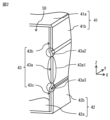
- FIG. 2 is a perspective view showing a configuration of a side plate portion of FIG. 1
- A) is a perspective view showing a state in which external pressure is applied to the housing of FIG. 1
- B) is a perspective view showing how the housing of FIG. 1 is deformed as a result of external pressure being applied to the housing.
- 2 is a perspective view showing a modified example of the configuration of part of the housing of FIG. 1;
- FIG. 1 is a perspective view showing the configuration of the power supply device 1.
- the power supply device 1 includes, for example, a plurality of battery units 10, a support 20, a circuit board 30, and a housing 40, as shown in FIG.
- the battery unit 10 is a battery block in which a plurality of unit cells (secondary batteries) are connected.
- the type of secondary battery is not particularly limited, it is, for example, a lithium ion secondary battery.
- the number of secondary batteries included in the battery unit 10 is not particularly limited and can be set arbitrarily.
- the support 20 is a shelf for supporting the plurality of battery units 10 and accommodating the battery units 10 , and is in contact with the inner wall of the housing 40 .
- the support 20 is fixed to the housing 40 with screws, for example.
- the circuit board 30 is a board for supplying power from the plurality of battery units 10 to an external circuit and for charging the plurality of battery units 10 from the external circuit.
- the housing 40 is an electronic component (or battery unit) housing for housing the plurality of battery units 10 , the support 20 and the circuit board 30 .
- a plurality of battery units 10 , supports 20 and circuit boards 30 are housed within a housing space 50 of housing 40 .
- FIG. 2 is a perspective view showing the configuration of part of the housing 40.
- the housing 40 includes an upper plate portion 41 (first plate portion), a lower plate portion 42 (second plate portion), and a pair of side plate portions 43 (third plate portion). , fourth plate portion).
- the upper plate portion 41 and the lower plate portion 42 are arranged in the Z direction (first direction) with an accommodation space 50 (predetermined gap) interposed therebetween.
- the third plate portion and the fourth plate portion are arranged across the accommodation space 50 in the X direction (second direction) orthogonal to the Z direction, and are arranged opposite each other across the accommodation space 50 in the X direction, for example.
- the third plate portion and the fourth plate portion are in contact with the upper plate portion 41 and the lower plate portion 42 .
- the upper plate portion 41 , the lower plate portion 42 and the pair of side plate portions 43 are configured to accommodate the plurality of secondary batteries 10 , the support 20 and the circuit board 30 .
- a housing space 50 is formed by the upper plate portion 41 , the lower plate portion 42 and the pair of side plate portions 43 .
- the upper plate portion 41, the lower plate portion 42, and the pair of side plate portions 43 all have a flat plate-like outer shape, and are made of mutually independent metal plates.
- the upper plate portion 41 includes an upper lid portion 41a forming the upper surface of the housing 40 and two bent portions 41b forming part of the side surfaces of the housing 40. have.
- the two bent portions 41b are connected to both ends in the X-axis direction of the upper cover portion 41a one by one.
- Each bent portion 41b is in contact with the surface of the end portion (upper plate portion 43b described later) of the side plate portion 43 on the side of the upper lid portion 41a, and overlaps at least a portion of the upper plate portion 43b when viewed from the X direction. . Therefore, the upper plate portion 41 is U-shaped.
- the upper plate portion 41 is formed, for example, by bending one sheet metal.
- the U-shape is not limited to a shape that draws an arc, and may be a shape that includes corners.
- each bent portion 41b may overlap the entire upper plate portion 43b as shown in FIG. At this time, the end of each bent portion 41b is arranged close to an upper bent portion 43a2, which will be described later, with a predetermined gap therebetween when viewed in the Z direction. In this case, for example, when the upper bent portion 43a2 is deformed by pressure from the Z direction, the end of the bent portion 41b can come into contact with the upper bent portion 43a2.
- the lower plate portion 42 includes a bottom lid portion 42a that forms the bottom surface of the housing 40, and two bent portions 42b that form part of the side surfaces of the housing 40. have.
- the two bent portions 42b are connected to both ends of the bottom lid portion 42a in the X-axis direction, respectively.
- One bent portion 42b is in contact with the surface of the end portion of one side plate portion 43 on the side of the bottom lid portion 42a (lower plate portion 43c, which will be described later), and overlaps at least a portion of the lower plate portion 43c.
- the other bent portion 42b is in contact with the surface of the end portion of the other side plate portion 43 on the side of the bottom cover portion 42a (lower plate portion 43c, which will be described later), and overlaps at least a portion of the lower plate portion 43c. Therefore, the lower plate portion 42 is U-shaped.
- the lower plate portion 42 is formed, for example, by bending one sheet metal.
- each bent portion 42b may overlap the entire lower plate portion 43c as shown in FIG. At this time, the end portion of each bent portion 42b is arranged close to a lower bent portion 43a3, which will be described later, with a predetermined gap therebetween when viewed in the Z direction. In this case, for example, when the lower bent portion 43a3 is deformed by pressure from the Z direction, the end of the bent portion 42b can come into contact with the lower bent portion 43a3.
- Each side plate portion 43 has, for example, a convex portion 43a projecting to the outside of the housing 40, as shown in FIGS.
- the convex portion 43a has a belt-like shape reaching both edges of the side plate portion 43 in the Y direction (third direction) orthogonal to the Z direction (first direction) and the X direction (second direction).
- the convex portion 43a has a hill portion 43a1, an upper bent portion 43a2 (first bent portion) and a lower bent portion 43a3 (second bent portion).
- the hill portion 43a1, the upper bent portion 43a2, and the lower bent portion 43a3 all have a belt-like shape extending in the extending direction (for example, the Y direction) of the convex portion 43a.
- the upper bent portion 43a2 and the lower bent portion 43a3 are arranged via the hill portion 43a1 in a direction (for example, Z direction) orthogonal to the extending direction of the convex portion 43a.
- the upper bent portion 43a2 is in contact with the edge of the hill portion 43a1 on the side of the first plate portion 41, and is inclined downward from the side of the hill portion 43a1 toward the side of the first plate portion 41 in the Z direction. That is, the surface of the upper bent portion 43a2 is an inclined surface (first inclined portion).
- the lower bent portion 43a3 is in contact with the edge of the hill portion 43a1 on the second plate portion 42 side, and is inclined downward from the hill portion 43a1 side toward the second plate portion 42 side in the Z direction. . That is, the surface of the lower bent portion 43a3 is an inclined surface (second inclined portion inclined in the opposite direction to the first inclined portion).
- a hill portion 43a1 of the convex portion 43a is, for example, a flat surface.
- the hill portion 43a1 of the convex portion 43a is formed on the side plate portion 43 at a position including the center in the Z direction.
- the center of the side plate portion 43 in the Z direction refers to the midpoint of the side plate portion 43 in the Z direction.
- the midpoint of the side plate portion 43 in the Z direction is the edge of the upper side plate portion 43b (the edge of the side plate portion 43 on the side of the upper side plate portion 43b) and the edge of the lower side plate portion 43c (the lower side plate portion 43c of the side plate portion 43).
- FIG. 3 illustrates three midpoints P1, P2, and P3 as midpoints of the side plate portion 43 in the Z direction.
- the midpoint P1 is positioned near one edge in the Y direction of the side plate portion 43 .
- the midpoint P3 is positioned near the other edge in the Y direction of the side plate portion 43 .
- the midpoint P2 is positioned between the midpoint P1 and the midpoint P3. For example, as shown in FIG.
- the hill portion 43a1 of the convex portion 43a is formed at a position including three midpoints P1, P2 and P3.
- the hill portion 43a1 of the convex portion 43a may be formed at a position including at least one of the three midpoints P1, P2 and P3.
- the three midpoints P1, P2, and P3 are conceptual.
- description of an opening for inserting a screw and the like is omitted.
- the "end” means an end in the Z direction. When unevenness is formed on the "edge", the tip of the convex portion is the "edge".
- the upper bent portion 43a2 and the lower bent portion 43a3 of the convex portion 43a are arranged symmetrically with respect to the center of the side plate portion 43 in the Z direction.
- the upper bent portion 43a2 and the lower bent portion 43a3 of the convex portion 43a are arranged symmetrically with respect to the center of the convex portion 43a in the Z direction.
- Each side plate portion 43 further has an upper side plate portion 43b and a lower side plate portion 43c, as shown in FIGS. 1 and 2, for example.
- the upper plate portion 43b is an end portion (fifth plate portion parallel to the first direction) of the side plate portion 43 parallel to the Z direction and extending from the upper bent portion 43a2 of the convex portion 43a.
- the lower plate portion 43c is an end portion of the side plate portion 43 parallel to the Z direction (sixth plate portion parallel to the first direction) extending from the lower bent portion 43a3 of the convex portion 43a. At least a portion of the upper plate portion 43b overlaps the end portion (bent portion 41b) on the side plate portion 43 side.
- At least a portion of the lower plate portion 43c overlaps the end portion (bent portion 42b) on the side plate portion 43 side.
- the portions of the upper plate portion 43b and the bent portion 41b that are in contact with each other are, for example, flat surfaces.
- the portions of the lower plate portion 43c and the bent portion 42b that are in contact with each other are, for example, flat surfaces.
- the side plate portion 43 is formed, for example, by bending one sheet metal.
- the end face on the upper plate portion 41 side (the end face of the upper plate portion 43b) is in contact with the surface of the upper plate portion 41 on the lower plate portion 42 side, and the end face on the lower plate portion 42 side (the lower plate portion The end surface of the portion 43c) is in contact with the surface of the lower plate portion 42 on the upper plate portion 41 side.
- the bent portion 41b and the upper plate portion 43b are superimposed on each other and fixed to each other by screws, for example.
- the bent portion 42b and the lower plate portion 43c are superimposed on each other and fixed to each other by screws, for example.
- the surface of the upper plate portion 41 on the lower plate portion 42 side is in contact with the support 20, and the upper plate portion 41 is fixed to the support 20 by screws, for example.
- the surface of the lower plate portion 42 on the side of the upper plate portion 41 is in contact with the support 20, and the lower plate portion 42 is fixed to the support 20 by screws, for example.
- secondary batteries that can be used in the battery unit 10 can include, for example, secondary batteries with a capacity exceeding several hundred mAh, which may actually lead to thermal runaway when an internal short circuit occurs.
- Secondary batteries generally exceeding several hundred mAh include, for example, laminate-type or cylindrical-type batteries.
- the charge/discharge principle of the secondary battery is not particularly limited, but the secondary battery is configured, for example, to obtain battery capacity by utilizing absorption and release of an electrode reactant.
- a secondary battery for example, includes an electrolyte together with a positive electrode and a negative electrode.
- the type of electrode reactant is not particularly limited, but specifically light metals such as alkali metals and alkaline earth metals.
- Alkali metals include lithium, sodium and potassium, and alkaline earth metals include beryllium, magnesium and calcium.
- a secondary battery whose battery capacity is obtained by utilizing the absorption and release of lithium is a so-called lithium ion secondary battery. In this lithium ion secondary battery, lithium is intercalated and deintercalated in an ionic state.
- a short circuit between the positive electrode and the negative electrode (hereinafter referred to as "internal short circuit") occurs due to foreign matter (for example, a nail or a metal piece) being stuck from the outside, the vicinity of the short circuit portion generates Joule heat. Then, thermal runaway may occur in the secondary battery depending on the state of generation of this gel heat.
- Such an internal short circuit of the secondary battery caused by foreign matter may occur, for example, when pressure is applied due to vibration or dropping during transportation. Therefore, when the secondary battery is housed in the housing, it is important to suppress the application of pressure to the secondary battery housed in the housing. Therefore, the inventor of the present application proposes a housing 40 capable of reducing the pressure applied to the contents inside.
- FIG. 4(A) is a perspective view showing a state in which pressure is applied to the upper plate portion 41 from the outside.
- FIG. 4B is a perspective view showing how the housing 40 deforms as a result of external pressure being applied to the upper plate portion 41 .
- each side plate portion 43 has a strip-shaped convex portion 43a reaching both edges in the Y direction (third direction) orthogonal to both the Z direction (first direction) and the X direction (second direction). is formed.
- the convex portion 43a includes an upper bent portion 43a2 that slopes downward from the side of the hill portion 43a1 of the convex portion 43a toward the upper plate portion 41 in the Z direction, and the hill of the convex portion 43a in the Z direction.
- a lower bent portion 43a3 that slopes downward from the portion 43a1 side toward the second plate portion 42 side is provided.
- the hill portion 43a1 of the convex portion 43a is formed on the side plate portion 43 at a position including the center in the Z direction.
- the upper plate portion 41, the lower plate portion 42 and the pair of side plate portions 43 are all made of mutually independent metal plates. Therefore, for example, when the side plate portion 43 is deformed, it is possible to suppress the deformation of the side plate portion 43 from applying pressure to the upper plate portion 41 and the lower plate portion 42 to cause deformation.
- each side plate portion 43 the end face on the upper plate portion 41 side (the end face of the upper plate portion 43b) is in contact with the surface of the upper plate portion 41 on the lower plate portion 42 side.
- side end surface (the end surface of the lower plate portion 43c) is in contact with the surface of the lower plate portion 42 on the upper plate portion 41 side.
- the upper plate portion 41 and the lower plate portion 42 are U-shaped.
- the ends of the upper plate portion 41 and the lower plate portion 42 can come into contact with the end faces and surfaces of the end portions of the side plate portions 43 .
- screwing or the like as described above can be easily performed.
- the contact between the surfaces includes not only the entire surfaces of both surfaces contacting each other, but also a case where only a part of both surfaces are in contact with each other and a gap is partially formed between both surfaces. include.
- the bent portion 41b of the upper plate portion 41 overlaps at least a portion of the upper plate portion 43b when viewed from the X direction
- the bent portion 42b of the lower plate portion 42 overlaps with the lower plate portion when viewed from the X direction. It overlaps with at least part of 43c.
- the upper bent portion 43a2 and the lower bent portion 43a3 are arranged symmetrically with respect to the center of the side plate portion 43 in the Z direction. As a result, the pressure received from the upper plate portion 41 and the lower plate portion 42 can be easily relieved, and the amount of deformation of the housing 40 can be reduced.
- the upper bent portion 43a2 and the lower bent portion 43a3 are arranged symmetrically with respect to the center of the convex portion 43a in the Z direction. As a result, the pressure received from the upper plate portion 41 and the lower plate portion 42 can be easily relieved, and the amount of deformation of the housing 40 can be reduced.
- the end of the bent portion 41b may be arranged along the upper bent portion 43a2. At this time, the end portion of the bent portion 41b is in contact with the upper bent portion 43a2 or arranged to face the upper bent portion 43a2. Further, in the present embodiment, for example, as shown in FIG. 5, the end of the bent portion 42b may be arranged along the lower bent portion 43a3. At this time, the end portion of the bent portion 42b is in contact with the lower bent portion 43a3 or opposed to the upper bent portion 43a2.
- the upper bent portion 43a2 and the lower bent portion 43a3 are arranged symmetrically with respect to the center in the Z direction of each side plate portion 43 .
- the upper bent portion 43a2 and the lower bent portion 43a3 are symmetrical with respect to the position near the upper plate portion 41 or the position near the lower plate portion 42 from the center of the side plate portion 43 in the Z direction. may be placed in
- the upper bent portion 43a2 and the lower bent portion 43a3 are arranged symmetrically with respect to the center in the Z direction of the convex portion 43a.
- the upper bent portion 43a2 and the lower bent portion 43a3 are symmetrical with respect to the position near the upper plate portion 41 or the position near the lower plate portion 42 from the center in the Z direction of the convex portion 43a. may be placed.
- both the upper plate portion 41 and the lower plate portion 42 are U-shaped.
- both the upper plate portion 41 and the lower plate portion 42 may be flat plates.
- both ends of the upper plate portion 41 in the X direction are fixed to the ends of the upper plate portion 43b, and both ends of the lower plate portion 42 in the X direction are fixed to the ends of the lower plate portion 43c. It may be fixed.
- the upper plate portion 41, the lower plate portion 42 and the pair of side plate portions 43 are all made of metal plates. However, in the above embodiment, at least one of the upper plate portion 41, the lower plate portion 42, and the pair of side plate portions 43 may be made of a highly rigid resin plate.
Landscapes
- Chemical & Material Sciences (AREA)
- Chemical Kinetics & Catalysis (AREA)
- Electrochemistry (AREA)
- General Chemical & Material Sciences (AREA)
- Battery Mounting, Suspending (AREA)
Priority Applications (2)
| Application Number | Priority Date | Filing Date | Title |
|---|---|---|---|
| JP2023563646A JPWO2023095699A1 (https=) | 2021-11-25 | 2022-11-16 | |
| US18/630,212 US20240258621A1 (en) | 2021-11-25 | 2024-04-09 | Housing for electronic components and power supply device |
Applications Claiming Priority (2)
| Application Number | Priority Date | Filing Date | Title |
|---|---|---|---|
| JP2021191225 | 2021-11-25 | ||
| JP2021-191225 | 2021-11-25 |
Related Child Applications (1)
| Application Number | Title | Priority Date | Filing Date |
|---|---|---|---|
| US18/630,212 Continuation US20240258621A1 (en) | 2021-11-25 | 2024-04-09 | Housing for electronic components and power supply device |
Publications (1)
| Publication Number | Publication Date |
|---|---|
| WO2023095699A1 true WO2023095699A1 (ja) | 2023-06-01 |
Family
ID=86539612
Family Applications (1)
| Application Number | Title | Priority Date | Filing Date |
|---|---|---|---|
| PCT/JP2022/042592 Ceased WO2023095699A1 (ja) | 2021-11-25 | 2022-11-16 | 電子部品用筐体および電源装置 |
Country Status (3)
| Country | Link |
|---|---|
| US (1) | US20240258621A1 (https=) |
| JP (1) | JPWO2023095699A1 (https=) |
| WO (1) | WO2023095699A1 (https=) |
Citations (3)
| Publication number | Priority date | Publication date | Assignee | Title |
|---|---|---|---|---|
| JPH07237457A (ja) * | 1994-03-01 | 1995-09-12 | Honda Motor Co Ltd | 電動車両のバッテリ冷却装置 |
| US20160229308A1 (en) * | 2015-02-11 | 2016-08-11 | Ford Global Technologies, Llc | Battery Enclosure Having T-Shaped Guides on the Outer Surface for Stiffeners and Impact Absorbing Elements |
| CN210182507U (zh) * | 2019-06-04 | 2020-03-24 | 恒大新能源科技集团有限公司 | 一种集成液冷式动力电池模组 |
Family Cites Families (1)
| Publication number | Priority date | Publication date | Assignee | Title |
|---|---|---|---|---|
| US4791527A (en) * | 1985-01-03 | 1988-12-13 | Motorola, Inc. | Portable radio transceiver housing structurally supported by battery |
-
2022
- 2022-11-16 WO PCT/JP2022/042592 patent/WO2023095699A1/ja not_active Ceased
- 2022-11-16 JP JP2023563646A patent/JPWO2023095699A1/ja active Pending
-
2024
- 2024-04-09 US US18/630,212 patent/US20240258621A1/en active Pending
Patent Citations (3)
| Publication number | Priority date | Publication date | Assignee | Title |
|---|---|---|---|---|
| JPH07237457A (ja) * | 1994-03-01 | 1995-09-12 | Honda Motor Co Ltd | 電動車両のバッテリ冷却装置 |
| US20160229308A1 (en) * | 2015-02-11 | 2016-08-11 | Ford Global Technologies, Llc | Battery Enclosure Having T-Shaped Guides on the Outer Surface for Stiffeners and Impact Absorbing Elements |
| CN210182507U (zh) * | 2019-06-04 | 2020-03-24 | 恒大新能源科技集团有限公司 | 一种集成液冷式动力电池模组 |
Also Published As
| Publication number | Publication date |
|---|---|
| US20240258621A1 (en) | 2024-08-01 |
| JPWO2023095699A1 (https=) | 2023-06-01 |
Similar Documents
| Publication | Publication Date | Title |
|---|---|---|
| EP3163650B1 (en) | Rechargeable battery module | |
| WO2019151037A1 (ja) | 電池モジュール及び電池パック | |
| JP7315544B2 (ja) | 溶接不良を防止することができる電池パックフレームを含む電池パック及びこれを製造するための押圧ジグ | |
| JP6241176B2 (ja) | 電源モジュール及び緩衝具 | |
| WO2019142645A1 (ja) | 蓄電装置 | |
| US20210218114A1 (en) | Secondary Battery Module | |
| KR102360159B1 (ko) | 배터리 모듈 | |
| JP2001110385A (ja) | 単位電池 | |
| US11476548B2 (en) | Battery module | |
| KR20170062845A (ko) | 구성이 간소화된 단위모듈을 포함하고 있는 전지모듈 | |
| US20170084885A1 (en) | Energy storage apparatus | |
| JP2016213104A (ja) | 電池パック | |
| JP2013168357A (ja) | 電源装置 | |
| KR20060037598A (ko) | 전지 모듈 | |
| KR20190054806A (ko) | 고정부를 포함하는 배터리 팩 | |
| CN117203836A (zh) | 电池模块、电池组以及包括电池组的能量存储设备 | |
| KR102788051B1 (ko) | 배터리 케이스용 하우징, 배터리의 케이스, 배터리 및 전기기기 | |
| KR101546661B1 (ko) | 파우치형 전지셀을 포함하는 각형화 전지 | |
| CN101752593A (zh) | 二次电池及其电池组和搭载二次电池的车辆 | |
| US20120208052A1 (en) | Battery pack | |
| EP4096001A1 (en) | Battery pack, power storage device and vehicle | |
| KR101783333B1 (ko) | 모듈용 단자 | |
| JP5135019B2 (ja) | 電池モジュール | |
| WO2023095699A1 (ja) | 電子部品用筐体および電源装置 | |
| CN221486708U (zh) | 电池及用电装置 |
Legal Events
| Date | Code | Title | Description |
|---|---|---|---|
| 121 | Ep: the epo has been informed by wipo that ep was designated in this application |
Ref document number: 22898483 Country of ref document: EP Kind code of ref document: A1 |
|
| WWE | Wipo information: entry into national phase |
Ref document number: 2023563646 Country of ref document: JP |
|
| NENP | Non-entry into the national phase |
Ref country code: DE |
|
| 122 | Ep: pct application non-entry in european phase |
Ref document number: 22898483 Country of ref document: EP Kind code of ref document: A1 |