WO2023095686A1 - ボイラシステム、及びボイラシステムの運転方法 - Google Patents
ボイラシステム、及びボイラシステムの運転方法 Download PDFInfo
- Publication number
- WO2023095686A1 WO2023095686A1 PCT/JP2022/042472 JP2022042472W WO2023095686A1 WO 2023095686 A1 WO2023095686 A1 WO 2023095686A1 JP 2022042472 W JP2022042472 W JP 2022042472W WO 2023095686 A1 WO2023095686 A1 WO 2023095686A1
- Authority
- WO
- WIPO (PCT)
- Prior art keywords
- ammonia
- boiler
- exhaust gas
- detected
- burner
- Prior art date
- Legal status (The legal status is an assumption and is not a legal conclusion. Google has not performed a legal analysis and makes no representation as to the accuracy of the status listed.)
- Ceased
Links
Images

Classifications
-
- B—PERFORMING OPERATIONS; TRANSPORTING
- B01—PHYSICAL OR CHEMICAL PROCESSES OR APPARATUS IN GENERAL
- B01D—SEPARATION
- B01D53/00—Separation of gases or vapours; Recovering vapours of volatile solvents from gases; Chemical or biological purification of waste gases, e.g. engine exhaust gases, smoke, fumes, flue gases, aerosols
- B01D53/14—Separation of gases or vapours; Recovering vapours of volatile solvents from gases; Chemical or biological purification of waste gases, e.g. engine exhaust gases, smoke, fumes, flue gases, aerosols by absorption
-
- B—PERFORMING OPERATIONS; TRANSPORTING
- B01—PHYSICAL OR CHEMICAL PROCESSES OR APPARATUS IN GENERAL
- B01D—SEPARATION
- B01D53/00—Separation of gases or vapours; Recovering vapours of volatile solvents from gases; Chemical or biological purification of waste gases, e.g. engine exhaust gases, smoke, fumes, flue gases, aerosols
- B01D53/14—Separation of gases or vapours; Recovering vapours of volatile solvents from gases; Chemical or biological purification of waste gases, e.g. engine exhaust gases, smoke, fumes, flue gases, aerosols by absorption
- B01D53/18—Absorbing units; Liquid distributors therefor
-
- B—PERFORMING OPERATIONS; TRANSPORTING
- B01—PHYSICAL OR CHEMICAL PROCESSES OR APPARATUS IN GENERAL
- B01D—SEPARATION
- B01D53/00—Separation of gases or vapours; Recovering vapours of volatile solvents from gases; Chemical or biological purification of waste gases, e.g. engine exhaust gases, smoke, fumes, flue gases, aerosols
- B01D53/34—Chemical or biological purification of waste gases
- B01D53/46—Removing components of defined structure
- B01D53/48—Sulfur compounds
- B01D53/50—Sulfur oxides
-
- B—PERFORMING OPERATIONS; TRANSPORTING
- B01—PHYSICAL OR CHEMICAL PROCESSES OR APPARATUS IN GENERAL
- B01D—SEPARATION
- B01D53/00—Separation of gases or vapours; Recovering vapours of volatile solvents from gases; Chemical or biological purification of waste gases, e.g. engine exhaust gases, smoke, fumes, flue gases, aerosols
- B01D53/34—Chemical or biological purification of waste gases
- B01D53/46—Removing components of defined structure
- B01D53/54—Nitrogen compounds
- B01D53/58—Ammonia
-
- B—PERFORMING OPERATIONS; TRANSPORTING
- B01—PHYSICAL OR CHEMICAL PROCESSES OR APPARATUS IN GENERAL
- B01D—SEPARATION
- B01D53/00—Separation of gases or vapours; Recovering vapours of volatile solvents from gases; Chemical or biological purification of waste gases, e.g. engine exhaust gases, smoke, fumes, flue gases, aerosols
- B01D53/34—Chemical or biological purification of waste gases
- B01D53/74—General processes for purification of waste gases; Apparatus or devices specially adapted therefor
- B01D53/77—Liquid phase processes
- B01D53/78—Liquid phase processes with gas-liquid contact
-
- F—MECHANICAL ENGINEERING; LIGHTING; HEATING; WEAPONS; BLASTING
- F22—STEAM GENERATION
- F22B—METHODS OF STEAM GENERATION; STEAM BOILERS
- F22B35/00—Control systems for steam boilers
-
- F—MECHANICAL ENGINEERING; LIGHTING; HEATING; WEAPONS; BLASTING
- F23—COMBUSTION APPARATUS; COMBUSTION PROCESSES
- F23J—REMOVAL OR TREATMENT OF COMBUSTION PRODUCTS OR COMBUSTION RESIDUES; FLUES
- F23J15/00—Arrangements of devices for treating smoke or fumes
-
- F—MECHANICAL ENGINEERING; LIGHTING; HEATING; WEAPONS; BLASTING
- F23—COMBUSTION APPARATUS; COMBUSTION PROCESSES
- F23N—REGULATING OR CONTROLLING COMBUSTION
- F23N5/00—Systems for controlling combustion
- F23N5/02—Systems for controlling combustion using devices responsive to thermal changes or to thermal expansion of a medium
Definitions
- the present disclosure relates to boiler systems and methods of operating boiler systems.
- This application claims priority based on Japanese Patent Application No. 2021-189859 filed with the Japan Patent Office on November 24, 2021, the content of which is incorporated herein.
- a boiler in which ammonia is supplied as fuel to the furnace is known.
- ammonia co-firing is performed in which ammonia is combusted together with coal in a furnace.
- the amount of ammonia used as fuel is very large compared to, for example, the amount of ammonia used as a catalyst for denitrification of combustion gas. Therefore, if an ammonia misfire occurs in the furnace, a large amount of unburned ammonia is produced. Although it is preferable to effectively suppress the release of this large amount of ammonia into the atmosphere with a simple configuration, the above patent document does not disclose a specific configuration.
- An object of the present disclosure is to provide a boiler system that can effectively suppress the release of ammonia into the atmosphere with a simple configuration, and a method of operating the boiler system.
- a boiler system includes: a boiler including an ammonia burner; a desulfurization device configured to desulfurize exhaust gas from the boiler; a controller; The controller is generating a stop command to stop the desulfurization process when a misfire of the ammonia burner is not detected and a boiler trip is detected, When the misfire of the ammonia burner is detected and the boiler trip is detected, the operation of the desulfurization device is continued so that the ammonia contained in the exhaust gas is recovered.
- a boiler system operating method includes: A stop command for stopping a desulfurization device configured to desulfurize the exhaust gas from the boiler when a misfire of an ammonia burner included in the boiler is not detected and a boiler trip is detected. to generate When the misfire of the ammonia burner is detected and the boiler trip is detected, the operation of the desulfurization device is continued so that the ammonia contained in the exhaust gas is recovered.
- FIG. 1 is a schematic configuration diagram of a boiler system according to one embodiment
- FIG. 1 is a conceptual configuration diagram of a desulfurization device according to one embodiment
- FIG. 1 is a conceptual explanatory diagram of a boiler according to one embodiment
- FIG. 4 is a conceptual illustration of an extraction section and an ammonia resupply line according to one embodiment
- FIG. 4 is a flowchart of a method for operating a boiler system according to one embodiment
- expressions denoting relative or absolute arrangements such as “in a direction”, “along a direction”, “parallel”, “perpendicular”, “center”, “concentric” or “coaxial” are strictly not only represents such an arrangement, but also represents a state of relative displacement with a tolerance or an angle or distance to the extent that the same function can be obtained.
- expressions such as “identical”, “equal”, and “homogeneous”, which express that things are in the same state not only express the state of being strictly equal, but also have tolerances or differences to the extent that the same function can be obtained. It shall also represent the existing state.
- expressions that express shapes such as squares and cylinders do not only represent shapes such as squares and cylinders in a geometrically strict sense, but also include irregularities and chamfers to the extent that the same effect can be obtained. Shapes including parts etc. shall also be represented.
- the expressions “comprising”, “including”, or “having” one component are not exclusive expressions excluding the presence of other components.
- symbol may be attached
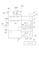
- FIG. 1 is a schematic configuration diagram showing a boiler system 1 including a boiler using ammonia fuel and other fuels other than ammonia fuel as main fuels according to the present embodiment.
- the boiler 10 included in the boiler system 1 of the present embodiment burns other fuel and ammonia fuel with a burner, and the heat generated by this combustion is heat-exchanged with feed water or steam to generate superheated steam. It's a boiler.
- biomass fuels and solid fuels such as coal are used.
- Coal as solid fuel is, for example, pulverized pulverized coal fuel.
- the ammonia fuel is liquid ammonia or ammonia gas. The following illustrates embodiments in which the ammonia fuel is liquid ammonia.
- the boiler 10 has a furnace 11 , combustion devices 20 and 50 and a combustion gas passage 12 .
- the furnace 11 has a hollow rectangular shape and is installed along the vertical direction.
- the furnace wall 101 which constitutes the inner wall surface of the furnace 11, is composed of a plurality of heat transfer tubes and fins connecting the heat transfer tubes. It is recovered by exchanging heat with steam and heat, and suppresses the temperature rise of the furnace wall 101 .
- the combustion devices 20 and 50 are installed in the lower region of the furnace 11.
- the combustion device 20 is configured to inject pulverized coal fuel into the interior of the furnace 11 .
- the combustion device 50 is configured to atomize the liquid ammonia with an atomizing fluid (spraying medium) and inject it into the furnace 11 .
- the atomized fluid of this embodiment is atomized vapor.
- Combustion device 20 has a plurality of burners 21 attached to furnace wall 101
- combustion device 50 has a plurality of ammonia burners 51 .
- the tip of each burner 21 is provided with an injection nozzle (not shown) configured to inject pulverized coal fuel into the furnace 11 .
- a two-fluid injection nozzle (not shown) configured to atomize liquid ammonia with an atomizing fluid and inject it into the furnace 11 is provided.
- the burners 21 and the ammonia burners 51 are arranged at regular intervals along the circumferential direction of the furnace 11 (for example, four burners installed at each corner of the rectangular furnace 11) as one set. are arranged in multiple stages along the In the example of FIG.
- one set of burners 21 is arranged in two stages, and one set of ammonia burners 51 is arranged in four stages.
- FIG. 1 for convenience of illustration, only two burners out of one set are shown, and the respective sets are denoted by reference numerals 21 and 51.
- the shape of the furnace, the number of stages of burners, the number of burners in one stage, the arrangement of burners, etc. are not limited to this embodiment.
- the combustion method in the furnace 11 may be either a swirling combustion method or a facing combustion method. Both the shape of the furnace 11 and the arrangement of the plurality of burners 21 and the plurality of ammonia burners 51 may be changed as appropriate according to the combustion method employed.
- the burner 21 of the combustion device 20 is connected to a plurality of mills ( pulverizer) 31A, 31B (hereinafter collectively referred to as "mill 31" in some cases).
- the mill 31 has, for example, a crushing table (not shown) supported therein so as to be driven and rotatable, and a plurality of crushing rollers (not shown) above the crushing table so as to be rotatable in conjunction with the rotation of the crushing table. It is a configured vertical roller mill.
- the solid fuel pulverized by the cooperation of the pulverizing roller and the pulverizing table is conveyed to a classifier (not shown) provided in the mill 31 by primary air (carrier gas, oxidizing gas) supplied to the mill 31. .
- the pulverized coal fuel is classified into pulverized coal fuel having a particle size smaller than that suitable for combustion in the burner 21 and coarse pulverized coal fuel having a larger particle size.
- the pulverized coal fuel passes through a classifier and is supplied to the burner 21 through the pulverized coal fuel supply pipe 22 together with primary air. Coarse pulverized coal fuel that has not passed through the classifier falls by its own weight onto the grinding table inside the mill 31 and is ground again.
- Each of the pulverized coal fuel supply pipes 22 is provided with a safety cutoff valve 25 for shutting off the pulverized coal fuel supply when a boiler trip occurs. A boiler trip detection method will be described later.
- the ammonia burner 51 of the combustion device 50 is connected to the fuel supply unit 90.
- the fuel supply unit 90 of this embodiment includes a supply line 92 connected to the combustion device 50 .
- liquid ammonia is supplied to combustion device 50 via supply line 92 while maintaining a liquid phase state.
- the supply line 92 includes an ammonia supply line for supplying liquid ammonia and an atomizing fluid supply line for supplying an atomizing fluid, which may be steam or the like, to the combustion device 50. and may be provided.
- the supply line 92 is also provided with at least one safety shutoff valve 95 configured to activate in the event of a boiler trip.
- An air register 23 is provided outside the furnace 11 at the position where the burner 21 and the ammonia burner 51 are mounted, and one end of an air duct (air duct) 24 is connected to the air register 23 .
- a forced draft fan (FDF) 32 is connected to the other end of the air duct 24 .
- the air supplied from the forced draft fan 32 is heated by an air preheater 42 installed in the air passage 24 (details will be described later), and passes through the air register 23 to the burner 21 to produce secondary air (combustion air, oxidizing air). gas) and introduced into the furnace 11.
- the combustion gas passage 12 is connected to the upper part of the furnace 11 in the vertical direction.
- superheaters 102A, 102B, and 102C (hereinafter collectively referred to as "superheaters 102" in some cases) are provided as heat exchangers for recovering the heat of the combustion gas.
- 103A, 103B (hereinafter sometimes collectively referred to as "reheater 103") and economizer 104 are provided, and the combustion gas generated in the furnace 11 and the inside of each heat exchanger are Heat exchange takes place between the circulating feedwater and steam.
- the arrangement and shape of each heat exchanger are not limited to the form described in FIG.
- the downstream side of the combustion gas passage 12 is connected to a flue 13 through which the combustion gas whose heat is recovered by the heat exchanger is discharged.
- An air preheater (air heater) 42 is provided between the flue 13 and the flue 24, and heat exchange is performed between the air flowing through the flue 24 and the combustion gas flowing through the flue 13, By heating the primary air supplied to the mill 31 and the secondary air supplied to the burner 21, further heat is recovered from the combustion gas after heat exchange with water or steam.
- a denitrification device 43 may be provided in the flue 13 at a position upstream of the air preheater 42 .
- the denitrification device 43 supplies a reducing agent, such as ammonia and urea water, which has the action of reducing nitrogen oxides, to the combustion gas flowing through the flue 13, and removes nitrogen oxides in the combustion gas supplied with the reducing agent.
- a reducing agent such as ammonia and urea water
- the gas duct 41 is provided with environmental equipment such as a dust collector 44 such as an electric dust collector for removing ash and the like in the combustion gas, a desulfurizer 46 for removing sulfur oxides, etc., and for guiding the exhaust gas to these environmental equipment.
- An induced draft fan (IDF: Induced Draft Fan) 45 is provided.
- the downstream end of the gas duct 41 is connected to a chimney 47, and the combustion gas treated by the environmental device is discharged out of the system as exhaust gas.
- pulverized and classified pulverized coal fuel is supplied to the burner 21 through the pulverized coal fuel supply pipe 22 together with primary air. Further, liquid ammonia and atomized fluid are supplied to the ammonia burner 51 from the fuel supply unit 90 . Further, the secondary air heated by the air preheater 42 is supplied to the burner 21 and the ammonia burner 51 from the air duct 24 via the air register 23 . The burner 21 blows into the furnace 11 a pulverized coal fuel mixture in which pulverized coal fuel and primary air are mixed, and also blows secondary air into the furnace 11 . The pulverized coal fuel mixture blown into the furnace 11 is ignited and reacts with secondary air to form a flame.
- the ammonia burner 51 blows secondary air into the furnace 11 together with liquid ammonia atomized by the atomizing fluid.
- the liquid ammonia blown into the furnace 11 is vaporized into fuel gas, which reacts with secondary air and burns.
- High-temperature combustion gas generated by combustion of pulverized coal fuel and fuel gas rises in the furnace 11 and flows into the combustion gas passage 12 .
- the timing at which the liquid ammonia is blown into the furnace 11 may be after the temperature inside the furnace 11 has risen to a certain temperature due to the combustion of the pulverized coal fuel.
- liquid ammonia may be blown into the furnace 11 and mixed combustion of the fuel gas in which the liquid ammonia is vaporized and the pulverized coal fuel may be carried out. Furthermore, after that, the blowing of the pulverized coal fuel may be stopped and ammonia mono-firing may be performed.
- air is used as the oxidizing gas (primary air, secondary air). Stable combustion is achieved in the furnace 11 by adjusting the ratio of the amounts to within an appropriate range.
- the combustion gas flowing into the combustion gas passage 12 exchanges heat with water and steam in the superheater 102, the reheater 103, and the economizer 104 arranged inside the combustion gas passage 12, and then is discharged to the flue 13.
- Nitrogen oxides are removed by the denitrification device 43
- heat is exchanged with primary air and secondary air by the air preheater 42
- ash etc. are removed by the dust collector 44 , and desulfurization device 46 .
- After the sulfur oxides are removed at they are discharged from the stack 47 to the outside of the system.
- the arrangement of each heat exchanger in the combustion gas passage 12 and each device in the flue 13 to the gas duct 41 does not necessarily have to be arranged in the order described above with respect to the combustion gas flow.
- the safety cutoff valves 25 and 95 are activated and the supply of fuel to the boiler 10 is immediately stopped. At this time, devices such as the denitrification device 43 are also stopped immediately. However, if the misfire of the ammonia burner 51 has occurred along with the boiler trip, the desulfurization device 46 continues to operate and recovers the unburned ammonia contained in the combustion gas, which is the exhaust gas from the boiler 10. (details will be described later).
- Solid fuels used in boilers may include coal, biomass fuels, petroleum coke (PC) fuels, petroleum residues, etc. instead of or in conjunction with pulverized coal fuels.
- the fuel for the boiler combined with ammonia fuel is not limited to solid fuel, and petroleum such as heavy oil, light oil and heavy oil, and liquid fuel such as factory waste liquid can also be used.
- gaseous fuels such as natural gas, various petroleum gases, and by-product gases generated in ironmaking processes can also be used.
- it can also be applied to a mixed combustion boiler that uses a combination of these various fuels.
- the ammonia fuel injected into the furnace may be ammonia gas instead of liquid ammonia.
- an atomizing fluid supply line may not be provided.
- the injection nozzle of the ammonia burner may be configured to inject ammonia gas.
- the ammonia supply line may be provided with at least one ammonia vaporizer for vaporizing the supplied liquid ammonia.
- the ammonia vaporizer may be configured to vaporize liquid ammonia using steam generated in the boiler, combustion gas in the boiler, or seawater outside the boiler system as a direct or indirect heat source.
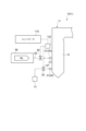
- FIG. 2 is a conceptual illustration of the desulfurization device 46 according to one embodiment.
- the boiler system 1 includes a desulfurization device 46 configured to desulfurize the exhaust gas from the boiler 10 .
- the desulfurization device 46 of the present embodiment employs a wet method in which desulfurization is performed using an absorbent.
- the absorption liquid is an alkaline aqueous solution using an alkaline reagent such as calcium hydroxide, sodium hydroxide (caustic soda), magnesium hydroxide, or ammonia.
- an alkaline reagent such as calcium hydroxide, sodium hydroxide (caustic soda), magnesium hydroxide, or ammonia.
- the absorption liquid is calcium hydroxide.
- the desulfurization device 46 includes a desulfurization tower 461 having an inlet 462 and an outlet 463 and having a reservoir of the absorbent formed therein, and a first spraying device configured to spray the absorbent inside the desulfurization tower 461. 61 and a limestone supply device 55 configured to supply limestone to the sump inside the desulfurization tower 461 .
- the exhaust gas from the boiler 10 flows into the desulfurization tower 461 via the inlet 462 and mixes with the absorbent sprayed by the first spraying device 61 .
- the exhaust gas is desulfurized by dissolving the sulfur oxides contained in the exhaust gas into the absorbent.
- the exhaust gas is then discharged from the desulfurizer 46 via the outlet 463 and released into the atmosphere through the stack 47 (see FIG. 1).
- the first spraying device 61 includes an absorbent circulation line 611 for circulating the absorbent forming the liquid reservoir of the desulfurization tower 461, a pump 612 provided in the absorbent circulation line 611, and the pump 612 driven to perform desulfurization. and a dispensing portion 615 to be supplied.
- Pump 612 is electrically connected to controller 110 .
- the absorbent forming the liquid pool is supplied to the sprinkling section 615 via the absorbent circulation line 611 .
- the spraying section 615 sprays the absorbent inside the desulfurization tower 461 .
- the limestone supply device 55 includes a limestone reservoir 551 which may be, for example, a limestone slurry tank, a limestone supply line 552 connected to the limestone reservoir 551 and the desulfurization tower 461, and a limestone supply section provided in the limestone supply line 552. 554.
- Limestone supply 554 is, for example, a pump electrically connected to controller 110 .
- the limestone supply unit 554 when the limestone supply unit 554 is driven based on a command output from the controller 110, the limestone stored in the limestone storage unit 551 is supplied to the liquid pool of the desulfurization tower 461.
- the desulfurization device 46 As described above performs a desulfurization treatment on the exhaust gas by spraying the absorbing liquid on the exhaust gas.
- the desulfurization device 46 stops operating based on a command from the controller 110 . Specifically, when a misfire of the ammonia burner 51 is not detected and a boiler trip is detected, the controller 110 generates a stop command to stop the desulfurization process.
- the stop command in this example is sent to the pump 612 and the limestone supply section 554 of the desulfurizer 46, thereby causing the desulfurizer 46 to stop operating.
- the desulfurization device 46 of this embodiment also has a function of recovering ammonia contained in the exhaust gas. Specifically, when a boiler trip occurs along with a misfire of the ammonia burner 51 (a specific detection method will be described later), the controller 110 determines not to generate the stop command. As a result, the desulfurization device 46 continues to operate. Although the desulfurization device 46 continues to spray the absorbent, the unburned ammonia contained in the exhaust gas is recovered by the absorbent, and the exhaust gas ammonia recovery process is executed. That is, the absorption liquid at this time also functions as washing water for recovering ammonia. By determining not to generate a stop command, the controller 110 continues the operation of the desulfurization device 46 so that the ammonia contained in the exhaust gas is recovered by such an absorbent. Below, the absorption liquid may be referred to as "washing water".
- the desulfurization device 46 Since the desulfurization device 46 has both a function of desulfurizing the exhaust gas and a function of recovering ammonia contained in the exhaust gas, the configuration of the boiler system 1 is simplified. As described above, the boiler system 1 that can effectively suppress the release of ammonia into the atmosphere using the desulfurization device 46 is realized.
- the desulfurization device 46 may employ a dry method in which desulfurization is performed using activated carbon, coal ash, or the like as an adsorbent.
- a semi-dry method spray dry method
- limestone slurry is sprayed to convert sulfur oxides into powder such as calcium sulfite for desulfurization.
- a desulfurization device 46 includes a spray device 60 configured to spray wash water for recovering ammonia into the exhaust gas flow path.
- the spraying device 60 is a device including the first spraying device 61 described above. According to the above configuration, since the sprayed cleaning water and the exhaust gas are well mixed, the ammonia contained in the exhaust gas can be efficiently recovered. Therefore, it is possible to further suppress the release of ammonia into the atmosphere.
- the spraying device 60 of this embodiment includes a second spraying device 62 in addition to the first spraying device 61 .
- the second spraying device 62 is, for example, a device dedicated to spraying cleaning water when a misfire of the ammonia burner 51 and a boiler trip occur. That is, the second spraying device 62 does not operate during normal operation of the boiler 10 .
- the second spraying device 62 includes a washing water circulation line 621 , a pump 622 and a spraying section 625 . Pump 622 is electrically connected to controller 110 .
- the second spraying device 62 has the same configuration as the first spraying device 61 already described.
- washing water circulation line 621 corresponds to the absorbent circulation line 611 (washing water circulation line 611) of the first spraying device 61 .
- the pump 622 corresponds to the pump 612 and the distributing section 625 corresponds to the distributing section 615, respectively.
- the description of each component and the operation content of the second spraying device 62 is omitted.
- the second spraying device 62 when a misfire of the ammonia burner 51 is detected and a boiler trip is detected, the second spraying device 62 in addition to the first spraying device 61 performs the washing water spraying operation. Therefore, more unburned ammonia contained in the exhaust gas can be recovered.
- the second spraying device 62 may be arranged at a position other than that shown in FIG. For example, it may be located at the inlet 462 of the desulfurizer 46 .
- the washing water sprayed by the second spraying device 62 may be water (industrial water). This is because even water can absorb a certain amount of ammonia if the supply amount is large.
- the spraying device 60 starts the operation of reducing the pH of the wash water after the desulfurization device 46 continues to operate (that is, after the ammonia burner 51 misfires and the boiler trips). Further includes a configured pH adjustment device 70 .
- the pH adjustment device 70 of this embodiment includes the limestone supply device 55 described above and a pH measurement device 71 electrically connected to the controller 110 .
- the controller 110 controls the limestone supply section 554 so that the pH of the liquid pool obtained based on the measurement result of the pH measuring device 71 is less than 7.
- the pH of the puddle is preferably adjusted to 3 or more and less than 6. For example, when the pH of the liquid pool exceeds 7, an additive such as a pH adjuster is introduced through an inlet (not shown) to lower the pH.
- the boiler system 1 also includes an ammonia measuring instrument 80 configured to measure the ammonia concentration of the exhaust gas on at least one of the inlet 462 side and the outlet 463 side of the desulfurization device 46 .
- the ammonia measuring device 80 electrically connected to the controller 110 includes a first ammonia measuring device 81 for measuring the ammonia concentration of the exhaust gas flowing into the desulfurization device 46 and an ammonia gas flowing out from the desulfurization device 46 . and a second ammonia meter 82 for measuring the concentration of ammonia in the exhaust gas.
- the controller 110 After the operation of the desulfurization device 46 continues, the controller 110 generates an ammonia recovery stop command for stopping the operation of the desulfurization device 46 on the condition that the measurement result of the ammonia measuring device 80 satisfies the prescribed return condition.
- the ammonia recovery stop command is a command similar to the stop command described above.
- the prescribed condition of the present embodiment is that the difference between the ammonia concentration on the inlet side determined based on the detection result of the first ammonia measuring device 81 and the ammonia concentration on the outlet side determined based on the detection result of the second ammonia measuring device 82 is It is below the specified concentration.
- ammonia meter 80 may comprise only one of first ammonia meter 81 or second ammonia meter 82 . For example, in an embodiment in which only the second ammonia meter 82 is provided, if the measurement result of the second ammonia meter 82 falls below the specified concentration, the return condition is satisfied.
- the desulfurization device 46 stops its continuous operation. Since unnecessary operation of the desulfurization device 46 is suppressed, efficient operation of the desulfurization device 46 is realized.
- the ammonia measuring instrument 80 is a laser gas measuring instrument configured to measure the concentration of ammonia based on the absorption spectrum of laser light transmitted through the exhaust gas.
- the first ammonia measuring instrument 81 includes a light emitting portion 81A for irradiating light toward the flow path of the exhaust gas on the side of the inlet 462, and a light receiving portion for receiving the light from the light emitting portion 81A. and a portion 81B.
- the second ammonia measuring instrument 82 has a light emitting section 82A for irradiating light toward the exhaust gas on the outlet 463 side, and a light receiving section 82B for receiving light from the light emitting section 82A.
- Ammonia gas has a unique optical absorption spectrum that absorbs light. Also, the absorbance correlates with the concentration of ammonia gas. Therefore, the ammonia concentration at each of the inlet 462 and the outlet 463 can be measured by spectrally analyzing the output signals output from the light receiving sections 81B and 82B. Further, the optical absorption spectrum of ammonia gas is different from the optical absorption spectra of sulfur compound gas, nitrogen compound gas, and carbon compound gas contained in the exhaust gas. Therefore, by performing gas measurement by the laser method, the concentration of ammonia gas can be accurately measured without being affected by other gases.
- the ammonia concentration can be measured more accurately because the ammonia measuring instrument 80 is a laser type gas measuring instrument. Therefore, it is possible to prevent erroneous detection that the concentration of unburned ammonia contained in the exhaust gas has decreased sufficiently even though the concentration of unburned ammonia has not actually decreased sufficiently. Therefore, it is possible to more reliably suppress the release of ammonia into the atmosphere after the desulfurization device 46 stops operating.
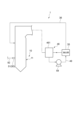
- FIG. 3 is a conceptual illustration of the boiler 10 according to one embodiment of the present disclosure.
- the boiler system 1 further includes a flame detector 121 configured to detect whether or not the ammonia burner 51 has misfired.
- the flame detector 121 is arranged inside a compartment (not shown) provided in the furnace 11 . Inside another compartment vertically adjacent to the compartment in which the flame detector 121 is arranged, an ammonia burner 51 may be arranged, for supplying secondary air mainly used for combustion of ammonia gas. of air nozzles (not shown) may be arranged.
- the controller 110 electrically connected to the flame detector 121 is configured to determine whether or not the ammonia burner 51 has misfired based on the detection result of the flame detector 121 . According to the above configuration, the controller 110 can accurately determine whether or not the ammonia burner 51 misfires based on the detection result of the flame detector 121 . Therefore, an erroneous determination as to whether the ammonia burner 51 has misfired is suppressed.
- the boiler system 1 of this embodiment further comprises an interlock 122 configured to cause a boiler trip when at least one of a plurality of stop conditions is satisfied.
- Interlock 122 is electrically connected, for example, to an emergency stop switch that is entered by an operator. That is, a shutdown condition that causes a boiler trip includes actuation of the emergency shutdown switch.
- the controller 110 is connected to at least one of a temperature gauge for measuring the temperature inside the furnace 11 (for example, the temperature of the nose wall) or a pressure gauge for measuring the pressure inside the furnace 11. may be If the measurement results of these measuring instruments do not satisfy the prescribed conditions, the interlock 122 is activated and the safety cutoff valves 25 and 95 are activated.
- the controller 110 of this embodiment is configured to determine the presence or absence of boiler trip based on the output signal from the interlock 122 . According to the above configuration, the controller 110 can more accurately determine the presence or absence of boiler trip based on the output signal of the interlock 122 .
- FIG. 4 is a conceptual illustration of extraction section 35 and ammonia resupply line 36 according to an embodiment of the present disclosure.
- a boiler system 1 includes an extraction unit 35 configured to extract ammonia from wash water, and an ammonia and a resupply line 36 .
- the extractor 35 of this embodiment is connected to a desulfurization tower 461 of the desulfurization device 46 via a wash water line 49 .
- the pump 59 provided in the washing water line 49 is driven to extract washing water from the liquid pool of the desulfurization tower 461. It is sent to the department 35.
- the extraction unit 35 which may be a stripper, for example, separates the cleaning water into ammonia gas and cleaning water from which the ammonia gas is recovered by subjecting the cleaning water to an ammonia stripping process.
- the treated wash water flows through the wash water line 49 and returns to the desulfurization tower 461 .
- Ammonia gas is supplied to boiler 10 through ammonia resupply line 36 .
- the ammonia burner 51 of the combustion device 50 injects ammonia gas instead of liquid ammonia
- the ammonia re-supply line 36 may be connected to the supply line 92 described above.
- the unburned ammonia gas contained in the exhaust gas is reused as ammonia fuel, so the boiler system 1 can be efficiently operated.
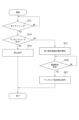
- FIG. 5 is a flowchart of a method for operating the boiler system 1 according to one embodiment.
- step may be abbreviated as "S”.
- the boiler 10 is operating normally and the first spraying device 61 of the desulfurization device 46 is in operation.
- the controller 110 determines whether or not a boiler trip has occurred (S11). For example, based on the output signal of interlock 122, controller 110 determines whether a boiler trip has occurred. When it is determined that the boiler trip has not occurred (S11: NO), the controller 110 waits and the boiler 10 continues to operate. If a misfire occurs in the ammonia burner 51 while the controller 110 is on standby, the ammonia injected from the ammonia burner 51 is burned by the flame generated inside the furnace 11 as the other fuel is burned. Therefore, even if the boiler 10 continues to operate, generation of a large amount of unburned ammonia in the furnace 11 is suppressed.
- the controller 110 determines whether a misfire has occurred in the ammonia burner 51 (S13). For example, whether or not the ammonia burner 51 misfires is determined based on the detection result of the flame detector 121, for example. When it is determined that the ammonia burner 51 has not misfired (S13: NO), the controller 110 operates the safety cutoff valves 25 and 95 to stop the fuel supply to the boiler 10, and generates a stop command. (S15). The generated stop command is sent to the desulfurization device 46, the desulfurization device 46 stops its operation, and the flow chart ends.
- the controller 110 determines not to generate a stop command, and shifts the process to S17. As a result, the desulfurization device 46 continues to operate, so the ammonia recovery process can be executed instead of the desulfurization process.
- the controller 110 starts the operation of the second spraying device 62 (S17). In the desulfurization device 46, the second spraying device 62 starts operating in addition to the first spraying device 61 that was operating before the boiler trip occurred, so more wash water is sprayed. Note that, when executing S17, the controller 110 may operate the pH measuring device 71 to reduce the pH of the cleaning water.
- the controller 110 determines whether or not the measurement result of the ammonia measuring instrument 80 satisfies the specified return condition (S19). The controller 110 waits until the measurement result satisfies the specified return condition (S19: NO), and the desulfurization device 46 performs the ammonia recovery operation. When it is determined that the return condition is satisfied (S19: YES), the controller 110 generates an ammonia recovery stop command and sends it to the desulfurization device 46 (S21). As a result, the desulfurization device 46 stops operating, the ammonia recovery process ends, and this flowchart also ends.
- a boiler system (1) according to at least one embodiment of the present disclosure, a boiler (10) including an ammonia burner (51); a desulfurization unit (46) configured to desulfurize exhaust gas from the boiler; a controller (110); The controller is generating a stop command to stop the desulfurization process when a misfire of the ammonia burner is not detected and a boiler trip is detected, When the misfire of the ammonia burner is detected and the boiler trip is detected, the operation of the desulfurization device is continued so that the ammonia contained in the exhaust gas is recovered.
- the desulfurization device has a function of desulfurizing the exhaust gas and a function of recovering ammonia contained in the exhaust gas, the configuration of the boiler system is simplified. As described above, a boiler system capable of effectively suppressing the release of ammonia into the atmosphere with a simple configuration is realized.
- the desulfurization device includes a sparging device (60) configured to sparse wash water for recovering the ammonia within the flow path of the exhaust gas.
- the sprayed cleaning water and the exhaust gas are well mixed, so that the ammonia contained in the exhaust gas can be efficiently recovered. Therefore, it is possible to further suppress the release of ammonia into the atmosphere.
- the spraying device is a first spraying device (61) configured to continue the operation of spraying the cleaning water, which has been performed before the boiler trip is detected, even after the operation of the desulfurization device continues; and a second spraying device (62) configured to start spraying of the wash water, which had been stopped before the boiler trip was detected, after operation of the desulfurization device continues.
- the second spraying device when a misfire of the ammonia burner is detected and a boiler trip is detected, the second spraying device performs the washing water spraying operation in addition to the first spraying device. Therefore, more unburned ammonia contained in the exhaust gas can be recovered.
- the desulfurizer further comprises a pH adjuster (70) configured to initiate operation to reduce the pH of the wash water after continued operation of the desulfurizer.
- the boiler system according to any one of 1) to 4) above, further comprising a flame detector (121) configured to detect the presence or absence of a misfire of the ammonia burner;
- the controller is configured to determine whether the ammonia burner has misfired based on the detection result of the flame detector.
- the controller can accurately determine whether or not the ammonia burner has misfired based on the detection result of the flame detector.
- the boiler system according to any one of 1) to 5) above, further comprising an interlock (122) configured to cause said boiler trip when at least one of a plurality of stop conditions is met;
- the controller is configured to determine whether the boiler trips based on an output signal from the interlock.
- the controller can more accurately determine the presence or absence of the boiler trip based on the interlock output signal.
- the boiler system according to any one of 1) to 6) above, further comprising an ammonia meter (80) configured to measure the ammonia concentration of the exhaust gas at least one of an inlet side and an outlet side of the desulfurizer;
- the controller After the operation of the desulfurization device continues, the controller generates an ammonia recovery stop command for stopping the operation of the desulfurization device on condition that the measurement result of the ammonia measuring device satisfies a prescribed return condition. configured as
- the desulfurization device stops the continuous operation. Therefore, unnecessary operation of the desulfurization apparatus is suppressed, and efficient operation of the desulfurization apparatus is realized.
- the ammonia measuring instrument is a laser type gas measuring instrument configured to measure the ammonia concentration based on the absorption spectrum of the laser beam that has passed through the exhaust gas.
- the ammonia concentration can be measured more accurately because the ammonia measuring instrument is a laser type gas measuring instrument. Therefore, it is possible to more reliably suppress release of ammonia into the atmosphere after the operation of the desulfurization apparatus is stopped.
- the desulfurization device includes a spraying device (60) configured to spray wash water for recovering the ammonia in the flow path of the exhaust gas, an extraction unit (35) configured to extract the ammonia from the wash water; and an ammonia re-supply line (36) configured to supply the ammonia extracted by the extraction unit to the boiler.
- the unburned ammonia contained in the exhaust gas is reused as ammonia fuel, so the boiler system can be efficiently operated.
- a method for operating a boiler system (1) comprising: A stop command for stopping a desulfurization device configured to desulfurize the exhaust gas from the boiler when a misfire of an ammonia burner included in the boiler is not detected and a boiler trip is detected. is generated (S15), When the misfire of the ammonia burner is detected and the boiler trip is detected, the operation of the desulfurization device is continued so that the ammonia contained in the exhaust gas is recovered (S13: YES).
- Reference Signs List 1 Boiler system 10 : Boiler 21 : Burner 35 : Extraction part 36 : Ammonia resupply line 46 : Desulfurization device 51 : Ammonia burner 60 : Spraying device 61 : First spraying device 62 : Second spraying device 70 : pH adjusting device 80 : ammonia measuring instrument 110 : controller 121 : flame detector 122 : interlock 462 : inlet 463 : outlet
Landscapes
- Engineering & Computer Science (AREA)
- Chemical & Material Sciences (AREA)
- Analytical Chemistry (AREA)
- General Chemical & Material Sciences (AREA)
- Oil, Petroleum & Natural Gas (AREA)
- Chemical Kinetics & Catalysis (AREA)
- Environmental & Geological Engineering (AREA)
- Mechanical Engineering (AREA)
- Health & Medical Sciences (AREA)
- Biomedical Technology (AREA)
- General Engineering & Computer Science (AREA)
- Combustion & Propulsion (AREA)
- Physics & Mathematics (AREA)
- Thermal Sciences (AREA)
- Treating Waste Gases (AREA)
- Control Of Combustion (AREA)
- Chimneys And Flues (AREA)
- Control Of Steam Boilers And Waste-Gas Boilers (AREA)
- Gas Separation By Absorption (AREA)
- Regulation And Control Of Combustion (AREA)
Abstract
Description
本願は、2021年11月24日に日本国特許庁に出願された特願2021-189859号に基づき優先権を主張し、その内容をここに援用する。
アンモニアバーナを含むボイラと、
前記ボイラからの排出ガスに脱硫処理を施すように構成される脱硫装置と、
コントローラと
を備え、
前記コントローラは、
前記アンモニアバーナの失火が検知されず、且つ、ボイラトリップが検知された場合には、前記脱硫処理を停止する停止指令を生成し、
前記アンモニアバーナの失火が検知され、且つ、前記ボイラトリップが検知された場合には、前記排出ガスに含まれるアンモニアが回収されるよう前記脱硫装置の運転を継続させるように構成される。
ボイラに含まれるアンモニアバーナの失火が検知されず、且つ、ボイラトリップが検知された場合には、前記ボイラからの排出ガスに脱硫処理を施すように構成される脱硫装置が停止するための停止指令を生成し、
前記アンモニアバーナの失火が検知され、且つ、前記ボイラトリップが検知された場合には、前記排出ガスに含まれるアンモニアが回収されるよう、前記脱硫装置の運転を継続させる。
また、実施形態として記載されている又は図面に示されている構成部品の寸法、材質、形状、その相対的配置等は、本開示の範囲をこれに限定する趣旨ではなく、単なる説明例にすぎない。
例えば、「ある方向に」、「ある方向に沿って」、「平行」、「直交」、「中心」、「同心」或いは「同軸」等の相対的或いは絶対的な配置を表す表現は、厳密にそのような配置を表すのみならず、公差、若しくは、同じ機能が得られる程度の角度や距離をもって相対的に変位している状態も表すものとする。
例えば、「同一」、「等しい」及び「均質」等の物事が等しい状態であることを表す表現は、厳密に等しい状態を表すのみならず、公差、若しくは、同じ機能が得られる程度の差が存在している状態も表すものとする。
例えば、四角形状や円筒形状等の形状を表す表現は、幾何学的に厳密な意味での四角形状や円筒形状等の形状を表すのみならず、同じ効果が得られる範囲で、凹凸部や面取り部等を含む形状も表すものとする。
一方、一の構成要素を「備える」、「含む」、又は、「有する」という表現は、他の構成要素の存在を除外する排他的な表現ではない。
なお、同様の構成については同じ符号を付し説明を省略することがある。
図1は、本実施形態のアンモニア燃料とアンモニア燃料以外の他燃料を主燃料とするボイラを備えるボイラシステム1を表す概略構成図である。
バーナ21とアンモニアバーナ51は、火炉11の周方向に沿って均等間隔で配設されたもの(例えば、四角形の火炉11の各コーナ部に設置された4個)を1セットとして、鉛直方向に沿って複数段配置されている。図1の例では、1セットのバーナ21が2段、1セットのアンモニアバーナ51が4段配置される。なお、図1では、図示の都合上、1セットのバーナのうちの2個のみを記載し、各セットに符合21、51を付している。火炉の形状やバーナの段数、一つの段におけるバーナの数、バーナの配置などは、この実施形態に限定されるものではない。
なお、火炉11における燃焼方式は、旋回燃焼方式また対向燃焼方式のいずれであってもよい。採用される燃焼方式に応じて、火炉11の形状と、複数のバーナ21及び複数のアンモニアバーナ51の配置はいずれも適宜変更されてよい。
煙道13の空気予熱器42より下流側には、ガスダクト41が連結されている。ガスダクト41には、燃焼ガス中の灰などを除去する電気集じん機などの集じん装置44や硫黄酸化物を除去する脱硫装置46などの環境装置、また、それらの環境装置に排ガスを導くための誘引通風機(IDF:Induced Draft Fan)45が設けられている。ガスダクト41の下流端部は、煙突47に連結されており、環境装置で処理された燃焼ガスが、排ガスとして系外に排出される。
バーナ21は、微粉炭燃料と一次空気とが混合した微粉炭燃料混合気を火炉11に吹き込むと共に、二次空気を火炉11に吹き込む。火炉11に吹き込まれた微粉炭燃料混合気が着火し、二次空気と反応することで火炎を形成する。アンモニアバーナ51は、アトマイズ流体によって微粒化された液体アンモニアと共に二次空気を火炉11に吹き込む。火炉11に吹き込まれた液体アンモニアは、気化して燃料ガスになり、二次空気と反応して燃焼する。
微粉炭燃料と燃料ガスの燃焼により生じる高温の燃焼ガスは、火炉11内を上昇し、燃焼ガス通路12に流入する。
なお、液体アンモニアが火炉11に吹き込まれるタイミングは、微粉炭燃料の燃焼によって火炉11内の温度が一定温度まで上昇した後であってもよい。例えば、ボイラ10の起動時に微粉炭燃料の専焼が行われたのち、液体アンモニアが火炉11に吹き込まれ、液体アンモニアが気化した燃料ガスと微粉炭燃料とのアンモニア混焼が行われてもよい。さらにその後、微粉炭燃料の吹き込みを停止し、アンモニア専焼が行われてもよい。
また、本実施形態では、酸化性ガス(一次空気、二次空気)として空気を用いるが、空気よりも酸素割合が多いものや逆に少ないものであってもよく、供給される燃料量に対する酸素量の比率を適正な範囲に調整することで、火炉11において安定した燃焼が実現される。
なお、アンモニア燃料と組み合わせるボイラの燃料としては、固体燃料に限らず、重油、軽油、重質油などの石油類や工場廃液などの液体燃料も使用することができる。また、天然ガスや各種石油ガス、製鉄プロセスなどで発生する副生ガスなどの気体燃料も使用することができる。
さらに、これらの各種燃料を組み合わせて使用する混焼ボイラにも適用することができる。
図2を参照し、本開示の一実施形態に係る脱硫装置46の詳細な構成を例示する。図2は、一実施形態に係る脱硫装置46の概念的な説明図である。
第2散布装置62は、洗浄水循環ライン621と、ポンプ622と、散布部625とを含む。ポンプ622はコントローラ110と電気的に接続されている。第2散布装置62は、既述の第1散布装置61と同様の構成を有する。即ち、洗浄水循環ライン621は、第1散布装置61の吸収液循環ライン611(洗浄水循環ライン611)に対応する。同様に、ポンプ622はポンプ612に、散布部625は散布部615にそれぞれ対応する。説明の重複を避けるために、第2散布装置62の各構成要素と動作内容とのそれぞれの説明を省略する。
なお、第2散布装置62は図2に示す位置以外に配置してもよい。例えば、脱硫装置46の入口462に配置してもよい。また、第2散布装置62で散布する洗浄水は、水(工業用水)でもよい。水でも供給量が多ければアンモニアを一定量吸収できるためである。
NH4 ++OH-→NH3↑+H2O (1)
上記構成によれば、アンモニアバーナ51の失火が検知され、且つボイラトリップが検知された場合には、散布される洗浄水のpHが低減するので、排出ガスに含まれる未燃のアンモニアをより効率的に回収することができる。
アンモニアガスは、光を吸収する特有の光吸収スペクトルを有する。また、吸光度は、アンモニアガスの濃度と相関する。従って、受光部81B、82Bのから出力される出力信号をそれぞれスペクトル分析することによって、入口462と出口463とのそれぞれにおけるアンモニア濃度の計測が可能となる。また、アンモニアガスの光吸収スペクトルは、排出ガスに含まれる硫黄化合物ガス、窒素化合物ガス、及び炭素化合物ガスのそれぞれの光吸収スペクトルとは異なる。従って、レーザ方式によるガス計測が行われることで、他のガスの影響を受けることなく、アンモニアガスの濃度を正確に計測することができる。
図3を参照し、アンモニアバーナ51の失火の検知方法とボイラトリップの検知方法の詳細を例示する。図3は、本開示の一実施形態に係るボイラ10の概念的な説明図である。
本開示の一実施形態に係るボイラシステム1は、アンモニアバーナ51の失火の有無を検知するように構成されるフレームディテクタ121をさらに備える。フレームディテクタ121は、火炉11に設けられるコンパートメント(図示外)の内側に配置される。フレームディテクタ121が配置されるコンパートメントと鉛直方向に隣接する別のコンパートメントの内側には、アンモニアバーナ51が配置されてもよいし、アンモニアガスの燃焼用に主に用いられる2次空気を供給するための空気ノズル(図示外)が配置されてもよい。
本実施形態のボイラシステム1は、複数の停止条件の少なくとも1つが充足された場合にボイラトリップを生じさせるように構成されるインターロック122をさらに備える。インターロック122は、例えば、オペレータによって入力される緊急停止スイッチと電気的に接続される。つまり、ボイラトリップを生じさせる停止条件には、緊急停止スイッチの作動が含まれる。他の実施形態では、コントローラ110は、火炉11内の温度(例えばノーズ壁の温度)を計測するための温度計測器、または、火炉11内圧力を計測するための圧力計測器の少なくとも一方と接続されてもよい。これら計測器の計測結果が規定条件を満たさなければ、インターロック122は作動し、安全遮断弁25、95が作動する。本実施形態のコントローラ110は、インターロック122からの出力信号に基づき、ボイラトリップの有無を判定するように構成される。上記構成によれば、コントローラ110は、インターロック122の出力信号に基づき、ボイラトリップの有無をより正確に判定することができる。
図4を参照し、脱硫装置46によって回収されたアンモニアの再利用方法について例示する。図4は、本開示の一実施形態に係る抽出部35とアンモニア再供給ライン36の概念的な説明図である。
本実施形態の抽出部35は、洗浄水ライン49を介して脱硫装置46の脱硫塔461と接続されている。例えば、脱硫装置46のアンモニア回収動作が終了してボイラ10が通常運転を再開する場合において、洗浄水ライン49に設けられるポンプ59が駆動することにより、脱硫塔461の液溜まりから洗浄水が抽出部35に送られる。例えばストリッパーであってもよい抽出部35は、洗浄水に対してアンモニアストリッピング処理を施すことにより、アンモニアガスと、アンモニアガスが回収された洗浄水とに分離する。処理が施された洗浄水は、洗浄水ライン49を流れて脱硫塔461に戻る。アンモニアガスは、アンモニア再供給ライン36を流れてボイラ10に供給される。なお、燃焼装置50のアンモニアバーナ51が、液体アンモニアの代わりにアンモニアガスを噴射する実施形態においては、アンモニア再供給ライン36は、上述の供給ライン92に接続されていてもよい。
図5を参照し、本開示の一実施形態に係るボイラシステム1の運転方法を例示する。図5は、一実施形態に係るボイラシステム1の運転方法のフローチャートである。以下の説明では、「ステップ」を「S」と略記する場合がある。このフローチャートの開始時、ボイラ10は通常運転をしており、脱硫装置46の第1散布装置61は動作している。
上述した幾つかの実施形態に記載の内容は、例えば以下のように把握される。
アンモニアバーナ(51)を含むボイラ(10)と、
前記ボイラからの排出ガスに脱硫処理を施すように構成される脱硫装置(46)と、
コントローラ(110)と
を備え、
前記コントローラは、
前記アンモニアバーナの失火が検知されず、且つ、ボイラトリップが検知された場合には、前記脱硫処理を停止する停止指令を生成し、
前記アンモニアバーナの失火が検知され、且つ、前記ボイラトリップが検知された場合には、前記排出ガスに含まれるアンモニアが回収されるよう前記脱硫装置の運転を継続させるように構成される。
前記脱硫装置は、前記排出ガスの流路内で前記アンモニアを回収するための洗浄水を散布するように構成される散布装置(60)を含む。
前記散布装置は、
前記ボイラトリップが検知される前から実行していた前記洗浄水の散布動作を、前記脱硫装置の運転の継続後も続けるように構成される第1散布装置(61)と、
前記ボイラトリップが検知される前には停止していた前記洗浄水の散布動作を、前記脱硫装置の運転の継続後に開始するように構成される第2散布装置(62)とを含む。
前記脱硫装置は、前記脱硫装置の運転の継続後に前記洗浄水のpHを低減させる動作を開始するように構成されるpH調整装置(70)をさらに含む。
前記アンモニアバーナの失火の有無を検知するように構成されるフレームディテクタ(121)をさらに備え、
前記コントローラは、前記フレームディテクタの検知結果に基づき、前記アンモニアバーナの失火の有無を判定するように構成される。
複数の停止条件の少なくとも1つが充足された場合に前記ボイラトリップを生じさせるように構成されるインターロック(122)をさらに備え、
前記コントローラは、前記インターロックからの出力信号に基づき、前記ボイラトリップの有無を判定するように構成される。
前記脱硫装置の入口側または出口側の少なくとも一方における前記排出ガスのアンモニア濃度を計測するように構成されるアンモニア計測器(80)をさらに備え、
前記コントローラは、前記脱硫装置の運転の継続後に、前記アンモニア計測器の計測結果が規定の復帰条件を充足したことを条件に、前記脱硫装置が運転を停止するためのアンモニア回収停止指令を生成するように構成される。
前記アンモニア計測器は、前記排出ガスを透過したレーザ光の吸収スペクトルに基づき前記アンモニア濃度を計測するように構成されるレーザ方式ガス計測器である。
前記脱硫装置は、前記排出ガスの流路内で前記アンモニアを回収するための洗浄水を散布するように構成される散布装置(60)を含み、
前記洗浄水から前記アンモニアを抽出するように構成される抽出部(35)と、
前記抽出部によって抽出された前記アンモニアを前記ボイラに供給するように構成されるアンモニア再供給ライン(36)と
をさらに備える。
ボイラに含まれるアンモニアバーナの失火が検知されず、且つ、ボイラトリップが検知された場合には、前記ボイラからの排出ガスに脱硫処理を施すように構成される脱硫装置が停止するための停止指令を生成し(S15)、
前記アンモニアバーナの失火が検知され、且つ、前記ボイラトリップが検知された場合には、前記排出ガスに含まれるアンモニアが回収されるよう、前記脱硫装置の運転を継続させる(S13:YES)。
10 :ボイラ
21 :バーナ
35 :抽出部
36 :アンモニア再供給ライン
46 :脱硫装置
51 :アンモニアバーナ
60 :散布装置
61 :第1散布装置
62 :第2散布装置
70 :pH調整装置
80 :アンモニア計測器
110 :コントローラ
121 :フレームディテクタ
122 :インターロック
462 :入口
463 :出口
Claims (10)
- アンモニアバーナを含むボイラと、
前記ボイラからの排出ガスに脱硫処理を施すように構成される脱硫装置と、
コントローラと
を備え、
前記コントローラは、
前記アンモニアバーナの失火が検知されず、且つ、ボイラトリップが検知された場合には、前記脱硫処理を停止する停止指令を生成し、
前記アンモニアバーナの失火が検知され、且つ、前記ボイラトリップが検知された場合には、前記排出ガスに含まれるアンモニアが回収されるよう前記脱硫装置の運転を継続させるように構成される
ボイラシステム。 - 前記脱硫装置は、前記排出ガスの流路内で前記アンモニアを回収するための洗浄水を散布するように構成される散布装置を含む
請求項1に記載のボイラシステム。 - 前記散布装置は、
前記ボイラトリップが検知される前から実行していた前記洗浄水の散布動作を、前記脱硫装置の運転の継続後も続けるように構成される第1散布装置と、
前記ボイラトリップが検知される前には停止していた前記洗浄水の散布動作を、前記脱硫装置の運転の継続後に開始するように構成される第2散布装置とを含む
請求項2に記載のボイラシステム。 - 前記脱硫装置は、前記脱硫装置の運転の継続後に前記洗浄水のpHを低減させる動作を開始するように構成されるpH調整装置をさらに含む
請求項2または3に記載のボイラシステム。 - 前記アンモニアバーナの失火の有無を検知するように構成されるフレームディテクタをさらに備え、
前記コントローラは、前記フレームディテクタの検知結果に基づき、前記アンモニアバーナの失火の有無を判定するように構成される
請求項1乃至3の何れか1項に記載のボイラシステム。 - 複数の停止条件の少なくとも1つが充足された場合に前記ボイラトリップを生じさせるように構成されるインターロックをさらに備え、
前記コントローラは、前記インターロックからの出力信号に基づき、前記ボイラトリップの有無を判定するように構成される
請求項1乃至3の何れか1項に記載のボイラシステム。 - 前記脱硫装置の入口側または出口側の少なくとも一方における前記排出ガスのアンモニア濃度を計測するように構成されるアンモニア計測器をさらに備え、
前記コントローラは、前記脱硫装置の運転の継続後に、前記アンモニア計測器の計測結果が規定の復帰条件を充足したことを条件に、前記脱硫装置が運転を停止するためのアンモニア回収停止指令を生成するように構成される
請求項1乃至3の何れか1項に記載のボイラシステム。 - 前記アンモニア計測器は、前記排出ガスを透過したレーザ光の吸収スペクトルに基づき前記アンモニア濃度を計測するように構成されるレーザ方式ガス計測器である
請求項7に記載のボイラシステム。 - 前記脱硫装置は、前記排出ガスの流路内で前記アンモニアを回収するための洗浄水を散布するように構成される散布装置を含み、
前記洗浄水から前記アンモニアを抽出するように構成される抽出部と、
前記抽出部によって抽出された前記アンモニアを前記ボイラに供給するように構成されるアンモニア再供給ラインと
をさらに備える請求項1乃至3の何れか1項に記載のボイラシステム。 - ボイラに含まれるアンモニアバーナの失火が検知されず、且つ、ボイラトリップが検知された場合には、前記ボイラからの排出ガスに脱硫処理を施すように構成される脱硫装置が停止するための停止指令を生成し、
前記アンモニアバーナの失火が検知され、且つ、前記ボイラトリップが検知された場合には、前記排出ガスに含まれるアンモニアが回収されるよう、前記脱硫装置の運転を継続させる
ボイラシステムの運転方法。
Priority Applications (1)
| Application Number | Priority Date | Filing Date | Title |
|---|---|---|---|
| KR1020247001133A KR102952925B1 (ko) | 2021-11-24 | 2022-11-16 | 보일러 시스템 및 보일러 시스템의 운전 방법 |
Applications Claiming Priority (2)
| Application Number | Priority Date | Filing Date | Title |
|---|---|---|---|
| JP2021189859A JP7630413B2 (ja) | 2021-11-24 | 2021-11-24 | ボイラシステム、及びボイラシステムの運転方法 |
| JP2021-189859 | 2021-11-24 |
Publications (1)
| Publication Number | Publication Date |
|---|---|
| WO2023095686A1 true WO2023095686A1 (ja) | 2023-06-01 |
Family
ID=86539566
Family Applications (1)
| Application Number | Title | Priority Date | Filing Date |
|---|---|---|---|
| PCT/JP2022/042472 Ceased WO2023095686A1 (ja) | 2021-11-24 | 2022-11-16 | ボイラシステム、及びボイラシステムの運転方法 |
Country Status (4)
| Country | Link |
|---|---|
| JP (2) | JP7630413B2 (ja) |
| KR (1) | KR102952925B1 (ja) |
| TW (1) | TWI861606B (ja) |
| WO (1) | WO2023095686A1 (ja) |
Cited By (3)
| Publication number | Priority date | Publication date | Assignee | Title |
|---|---|---|---|---|
| JP2024074502A (ja) * | 2022-11-21 | 2024-05-31 | 株式会社大気社 | 回収システム |
| WO2025004475A1 (ja) * | 2023-06-27 | 2025-01-02 | 三菱重工業株式会社 | 予混合装置及びボイラ並びにボイラの改造方法 |
| EP4596968A1 (en) * | 2024-01-30 | 2025-08-06 | Alfa Laval Corporate AB | Marine boiler with injector for sncr agent |
Families Citing this family (2)
| Publication number | Priority date | Publication date | Assignee | Title |
|---|---|---|---|---|
| JP7630413B2 (ja) * | 2021-11-24 | 2025-02-17 | 三菱重工業株式会社 | ボイラシステム、及びボイラシステムの運転方法 |
| JPWO2025032763A1 (ja) * | 2023-08-09 | 2025-02-13 |
Citations (5)
| Publication number | Priority date | Publication date | Assignee | Title |
|---|---|---|---|---|
| JPH02199213A (ja) * | 1989-01-26 | 1990-08-07 | Mitsubishi Motors Corp | エンジンの排気ガス浄化装置 |
| JPH0828855A (ja) * | 1994-07-11 | 1996-02-02 | Babcock Hitachi Kk | 排煙脱硫装置 |
| JP2004223388A (ja) * | 2003-01-22 | 2004-08-12 | Mitsubishi Heavy Ind Ltd | 排煙処理方法及び同装置 |
| JP2019098204A (ja) * | 2017-11-29 | 2019-06-24 | オルガノ株式会社 | アンモニア処理方法及び装置 |
| JP2019178823A (ja) * | 2018-03-30 | 2019-10-17 | 三菱日立パワーシステムズ株式会社 | 火力発電プラント、混焼ボイラ及びボイラの改造方法 |
Family Cites Families (11)
| Publication number | Priority date | Publication date | Assignee | Title |
|---|---|---|---|---|
| JPH01157903U (ja) * | 1988-04-25 | 1989-10-31 | ||
| JPH0652128B2 (ja) * | 1989-05-17 | 1994-07-06 | 三浦工業株式会社 | ボイラーの燃焼制御方法 |
| CN100487311C (zh) * | 2004-10-28 | 2009-05-13 | 日立造船株式会社 | 废弃物的焚烧设备 |
| JP5445027B2 (ja) * | 2009-10-23 | 2014-03-19 | 株式会社Ihi | 循環流動層ガス化設備のガス処理方法及び装置 |
| CN103301732B (zh) * | 2013-06-20 | 2015-01-21 | 义马煤业集团煤生化高科技工程有限公司 | 一种含硫化氢的化工酸性废气回收治理装置及工艺 |
| CN106871102B (zh) * | 2016-12-28 | 2019-05-24 | 神华集团有限责任公司 | 全负荷的脱硝工艺 |
| WO2019057108A1 (zh) * | 2017-09-22 | 2019-03-28 | 邹立松 | 脱硝工艺及装置、燃烧发电工艺及系统、电动汽车和浮空器 |
| JP7249109B2 (ja) * | 2018-05-11 | 2023-03-30 | 株式会社Ihi | 蒸気発生設備 |
| JP2020112280A (ja) | 2019-01-08 | 2020-07-27 | 一般財団法人電力中央研究所 | アンモニアを混焼できるボイラ装置及び火力発電設備 |
| CN110538557A (zh) * | 2019-09-04 | 2019-12-06 | 无锡市东方工业节能环保有限公司 | 烧结机脱硫脱硝消白一体化系统 |
| JP7630413B2 (ja) * | 2021-11-24 | 2025-02-17 | 三菱重工業株式会社 | ボイラシステム、及びボイラシステムの運転方法 |
-
2021
- 2021-11-24 JP JP2021189859A patent/JP7630413B2/ja active Active
-
2022
- 2022-11-16 KR KR1020247001133A patent/KR102952925B1/ko active Active
- 2022-11-16 WO PCT/JP2022/042472 patent/WO2023095686A1/ja not_active Ceased
- 2022-11-22 TW TW111144538A patent/TWI861606B/zh active
-
2025
- 2025-02-04 JP JP2025016568A patent/JP2025072479A/ja active Pending
Patent Citations (5)
| Publication number | Priority date | Publication date | Assignee | Title |
|---|---|---|---|---|
| JPH02199213A (ja) * | 1989-01-26 | 1990-08-07 | Mitsubishi Motors Corp | エンジンの排気ガス浄化装置 |
| JPH0828855A (ja) * | 1994-07-11 | 1996-02-02 | Babcock Hitachi Kk | 排煙脱硫装置 |
| JP2004223388A (ja) * | 2003-01-22 | 2004-08-12 | Mitsubishi Heavy Ind Ltd | 排煙処理方法及び同装置 |
| JP2019098204A (ja) * | 2017-11-29 | 2019-06-24 | オルガノ株式会社 | アンモニア処理方法及び装置 |
| JP2019178823A (ja) * | 2018-03-30 | 2019-10-17 | 三菱日立パワーシステムズ株式会社 | 火力発電プラント、混焼ボイラ及びボイラの改造方法 |
Cited By (5)
| Publication number | Priority date | Publication date | Assignee | Title |
|---|---|---|---|---|
| JP2024074502A (ja) * | 2022-11-21 | 2024-05-31 | 株式会社大気社 | 回収システム |
| JP7510479B2 (ja) | 2022-11-21 | 2024-07-03 | 株式会社大気社 | 回収システム |
| WO2025004475A1 (ja) * | 2023-06-27 | 2025-01-02 | 三菱重工業株式会社 | 予混合装置及びボイラ並びにボイラの改造方法 |
| EP4596968A1 (en) * | 2024-01-30 | 2025-08-06 | Alfa Laval Corporate AB | Marine boiler with injector for sncr agent |
| WO2025162716A1 (en) * | 2024-01-30 | 2025-08-07 | Alfa Laval Corporate Ab | Marine boiler with injector for sncr agent |
Also Published As
| Publication number | Publication date |
|---|---|
| TWI861606B (zh) | 2024-11-11 |
| JP2025072479A (ja) | 2025-05-09 |
| JP7630413B2 (ja) | 2025-02-17 |
| KR102952925B1 (ko) | 2026-04-16 |
| TW202332868A (zh) | 2023-08-16 |
| KR20240021263A (ko) | 2024-02-16 |
| JP2023076868A (ja) | 2023-06-05 |
Similar Documents
| Publication | Publication Date | Title |
|---|---|---|
| JP7630413B2 (ja) | ボイラシステム、及びボイラシステムの運転方法 | |
| JP2014500942A (ja) | 排ガスの焼却におけるNOx排出を低減する方法および装置 | |
| JP7455781B2 (ja) | 発電プラント用のアンモニア供給ユニット、発電プラント用のアンモニア気化処理方法、及び発電プラント | |
| WO2023095690A1 (ja) | アンモニア燃料供給ユニット、及びボイラシステム | |
| TWI818615B (zh) | 氨燃料供應單元、發電廠、以及鍋爐之運轉方法 | |
| WO2014103682A1 (ja) | 排ガス処理設備およびこれを用いるガスタービン発電システム | |
| JP6263492B2 (ja) | ボイラ及びボイラの燃焼制御方法 | |
| CN120659954A (zh) | 燃烧系统及锅炉系统以及燃烧系统的运行方法 | |
| JP2011120981A (ja) | 酸素燃焼方式の排ガス処理装置と該排ガス処理装置の運用方法 | |
| FI129360B (fi) | Menetelmä savukaasupäästöjen vähentämiseksi ja kattila | |
| WO2022181053A1 (ja) | 清掃装置及び伝熱管の清掃方法 | |
| JP6258160B2 (ja) | 燃焼バーナ及びボイラ | |
| JP2024074568A (ja) | アンモニア燃料漏洩検出装置及びボイラシステム並びにアンモニア燃料漏洩検出方法 | |
| JP2025002654A (ja) | バーナ及びボイラ並びに燃焼方法 | |
| KR101175768B1 (ko) | 미분탄 순산소 연소 시스템 | |
| JP7229796B2 (ja) | Bfgバーナ装置、これを備えたボイラ、及びbfgバーナ装置の運転方法 | |
| JP2024111931A (ja) | 排煙脱硫システム及びこれを備えたプラント並びに排煙脱硫システムの運転方法 | |
| JPH0972503A (ja) | 微粉炭燃焼方法及び装置 | |
| WO2024101074A1 (ja) | 脱硝制御装置及び脱硝装置 | |
| JP2025154300A (ja) | バーナ及びこれを備えたボイラ | |
| JP2024145455A (ja) | ボイラシステムおよびボイラシステムの運転方法 | |
| JPH10318514A (ja) | 焼却炉およびその燃焼方法 | |
| WO2026018585A1 (ja) | バーナ及びこれを備えたボイラ | |
| KR20250140594A (ko) | 폐기물 소각설비 | |
| Seltzer et al. | Near-zero emissions oxy-combustion flue gas purification-power plant performance |
Legal Events
| Date | Code | Title | Description |
|---|---|---|---|
| 121 | Ep: the epo has been informed by wipo that ep was designated in this application |
Ref document number: 22898470 Country of ref document: EP Kind code of ref document: A1 |
|
| WWE | Wipo information: entry into national phase |
Ref document number: 202417000531 Country of ref document: IN |
|
| ENP | Entry into the national phase |
Ref document number: 20247001133 Country of ref document: KR Kind code of ref document: A |
|
| WWE | Wipo information: entry into national phase |
Ref document number: 1020247001133 Country of ref document: KR |
|
| WWE | Wipo information: entry into national phase |
Ref document number: 2401000820 Country of ref document: TH |
|
| NENP | Non-entry into the national phase |
Ref country code: DE |
|
| 122 | Ep: pct application non-entry in european phase |
Ref document number: 22898470 Country of ref document: EP Kind code of ref document: A1 |