WO2023095562A1 - Procédé de soudage à l'arc et dispositif de soudage à l'arc - Google Patents
Procédé de soudage à l'arc et dispositif de soudage à l'arc Download PDFInfo
- Publication number
- WO2023095562A1 WO2023095562A1 PCT/JP2022/040631 JP2022040631W WO2023095562A1 WO 2023095562 A1 WO2023095562 A1 WO 2023095562A1 JP 2022040631 W JP2022040631 W JP 2022040631W WO 2023095562 A1 WO2023095562 A1 WO 2023095562A1
- Authority
- WO
- WIPO (PCT)
- Prior art keywords
- welding
- short
- pulse
- circuit
- arc
- Prior art date
Links
- 238000003466 welding Methods 0.000 title claims abstract description 919
- 238000000034 method Methods 0.000 title claims description 40
- 238000009941 weaving Methods 0.000 claims abstract description 41
- 239000000203 mixture Substances 0.000 description 80
- 239000011324 bead Substances 0.000 description 31
- 238000010586 diagram Methods 0.000 description 13
- 239000007789 gas Substances 0.000 description 9
- CURLTUGMZLYLDI-UHFFFAOYSA-N Carbon dioxide Chemical compound O=C=O CURLTUGMZLYLDI-UHFFFAOYSA-N 0.000 description 6
- 230000035515 penetration Effects 0.000 description 6
- 239000000463 material Substances 0.000 description 5
- 230000000737 periodic effect Effects 0.000 description 5
- 229910001209 Low-carbon steel Inorganic materials 0.000 description 3
- 229910052786 argon Inorganic materials 0.000 description 3
- 229910002092 carbon dioxide Inorganic materials 0.000 description 3
- 239000000155 melt Substances 0.000 description 3
- 230000007704 transition Effects 0.000 description 3
- XKRFYHLGVUSROY-UHFFFAOYSA-N Argon Chemical compound [Ar] XKRFYHLGVUSROY-UHFFFAOYSA-N 0.000 description 2
- XAGFODPZIPBFFR-UHFFFAOYSA-N aluminium Chemical compound [Al] XAGFODPZIPBFFR-UHFFFAOYSA-N 0.000 description 2
- 229910052782 aluminium Inorganic materials 0.000 description 2
- 238000001816 cooling Methods 0.000 description 2
- 230000002596 correlated effect Effects 0.000 description 2
- 238000001514 detection method Methods 0.000 description 2
- 230000000694 effects Effects 0.000 description 2
- 230000000007 visual effect Effects 0.000 description 2
- 229910000838 Al alloy Inorganic materials 0.000 description 1
- 230000001154 acute effect Effects 0.000 description 1
- 230000015572 biosynthetic process Effects 0.000 description 1
- 239000001569 carbon dioxide Substances 0.000 description 1
- 238000006243 chemical reaction Methods 0.000 description 1
- 230000000052 comparative effect Effects 0.000 description 1
- 230000001276 controlling effect Effects 0.000 description 1
- 230000000875 corresponding effect Effects 0.000 description 1
- 230000000630 rising effect Effects 0.000 description 1
- 238000000926 separation method Methods 0.000 description 1
- 238000009751 slip forming Methods 0.000 description 1
- 239000010935 stainless steel Substances 0.000 description 1
- 229910001220 stainless steel Inorganic materials 0.000 description 1
- 230000001960 triggered effect Effects 0.000 description 1
Images


Classifications
-
- B—PERFORMING OPERATIONS; TRANSPORTING
- B23—MACHINE TOOLS; METAL-WORKING NOT OTHERWISE PROVIDED FOR
- B23K—SOLDERING OR UNSOLDERING; WELDING; CLADDING OR PLATING BY SOLDERING OR WELDING; CUTTING BY APPLYING HEAT LOCALLY, e.g. FLAME CUTTING; WORKING BY LASER BEAM
- B23K9/00—Arc welding or cutting
- B23K9/06—Arrangements or circuits for starting the arc, e.g. by generating ignition voltage, or for stabilising the arc
- B23K9/073—Stabilising the arc
-
- B—PERFORMING OPERATIONS; TRANSPORTING
- B23—MACHINE TOOLS; METAL-WORKING NOT OTHERWISE PROVIDED FOR
- B23K—SOLDERING OR UNSOLDERING; WELDING; CLADDING OR PLATING BY SOLDERING OR WELDING; CUTTING BY APPLYING HEAT LOCALLY, e.g. FLAME CUTTING; WORKING BY LASER BEAM
- B23K9/00—Arc welding or cutting
- B23K9/09—Arrangements or circuits for arc welding with pulsed current or voltage
-
- B—PERFORMING OPERATIONS; TRANSPORTING
- B23—MACHINE TOOLS; METAL-WORKING NOT OTHERWISE PROVIDED FOR
- B23K—SOLDERING OR UNSOLDERING; WELDING; CLADDING OR PLATING BY SOLDERING OR WELDING; CUTTING BY APPLYING HEAT LOCALLY, e.g. FLAME CUTTING; WORKING BY LASER BEAM
- B23K9/00—Arc welding or cutting
- B23K9/095—Monitoring or automatic control of welding parameters
-
- B—PERFORMING OPERATIONS; TRANSPORTING
- B23—MACHINE TOOLS; METAL-WORKING NOT OTHERWISE PROVIDED FOR
- B23K—SOLDERING OR UNSOLDERING; WELDING; CLADDING OR PLATING BY SOLDERING OR WELDING; CUTTING BY APPLYING HEAT LOCALLY, e.g. FLAME CUTTING; WORKING BY LASER BEAM
- B23K9/00—Arc welding or cutting
- B23K9/12—Automatic feeding or moving of electrodes or work for spot or seam welding or cutting
Definitions
- the present invention relates to an arc welding method and an arc welding apparatus.
- Patent Document 1 in consumable electrode type arc welding in which pulse welding and short-circuit welding are alternately repeated, the welding current immediately before the transition from pulse welding to short-circuit welding is made lower than the base current in the pulse. is disclosed.
- the present invention has been made in view of this point, and its purpose is to improve the bonding quality between members having different heat capacities.
- a first aspect is an arc welding method in which a welding wire, which is a consumable electrode, is fed toward a welding object, and an arc is generated between the welding wire and the welding object for welding,
- the object to be welded has a first member and a second member having a larger heat capacity than the first member, and alternately crosses the boundary position between the first member and the second member a plurality of times, welding while weaving a welding torch; and performing a first weld to the first member and a second weld to the second member during the weaving operation. wherein at least short-circuit welding is performed in the first welding, and at least pulse welding is performed in the second welding.
- the second member has a larger heat capacity than the first member. Welding is performed while weaving the welding torch so as to alternately cross the boundary position between the first member and the second member a plurality of times. During the weaving operation, a first weld is made to the first member while a second weld is made to the second member. At least short-circuit welding is performed in the first welding. At least pulse welding is performed in the second welding.
- a second aspect is the arc welding method of the first aspect, wherein in at least one of the first welding and the second welding, a short-circuit welding period in which the short-circuit welding is performed and a pulse welding period in which the pulse welding is performed alternately.
- a third weld is made by switching to .
- the third welding is performed in at least one of the first welding and the second welding.
- the third weld has intermediate properties of higher heat input than short-circuit welding and lower heat input than pulse welding.
- a third aspect is the arc welding method of the second aspect, wherein when the third welding is performed in the first welding, the ratio of the short-circuit welding period of the short-circuit welding performed during the third welding is set to the pulse and when the third welding is performed in the second welding, the ratio of the pulse welding period of the pulse welding performed during the third welding is set to the above-mentioned pulse welding period of the short-circuit welding. greater than the short-circuit welding period.
- the third aspect includes a short-circuit welding period in which short-circuit welding is performed and a pulse welding period in which pulse welding is performed.
- a short-circuit welding period in which short-circuit welding is performed When performing the third welding of the first member having a small heat capacity, the proportion of the short-circuit welding period during which short-circuit welding with low heat input is performed is increased compared to pulse welding. Further, when the second member having a large heat capacity is subjected to the third welding, the proportion of the pulse welding period in which high heat input pulse welding is performed is increased. Thereby, the 3rd welding can be performed under suitable conditions.
- a fourth aspect is the arc welding method of the second or third aspect, wherein in the second welding, before the welding torch crosses the boundary position so as to move from the second member to the first member, A step of switching in order of the pulse welding, the third welding, and the short-circuit welding is provided.
- the welding torch before the welding torch is moved from the second member with a large heat capacity toward the first member with a small heat capacity, the welding is gradually shifted to short-circuit welding. As a result, sudden changes in heat input can be suppressed while coordinating pulse welding, third welding, and short-circuit welding.
- a fifth aspect is the arc welding method according to any one of the second to fourth aspects, wherein in the third welding, at least one of the number of pulses during pulse welding and the number of short circuits during short-circuit welding is gradually changed.
- a sixth aspect is the arc welding method according to any one of the first to fifth aspects, wherein the welding torch is applied when crossing the boundary position so as to move from the first member to the second member.
- a welding current is greater than the welding current applied before the welding torch crosses the boundary location.
- the welding current applied when crossing the boundary position is an average welding current that is an average current as a moving average of the welding current, and the average welding current applied to the welding wire when crossing the boundary position
- a seventh aspect is the arc welding method according to any one of the second to sixth aspects, wherein when the welding torch crosses the boundary position from the second member toward the first member, the The percentage of short-circuit times of the short-circuit welds in weld 3 is greater than the percentage of short-circuit times of the short-circuit welds in weld 3 before the welding torch crosses the boundary location.
- the ratio of the number of short circuits when the welding torch crosses the boundary position is made larger than the ratio of the number of short circuits before the welding torch crosses the boundary position, and when the welding torch crosses the boundary position from before crossing the boundary position, short circuits
- the ratio of the number of times it is possible to ensure bead build-up at the boundary position in a low heat input state.
- a step formed at the boundary between the thin plate and the thick plate can be filled.
- An eighth aspect is the arc welding method according to any one of the first to seventh aspects, wherein the weaving operation is a spiral weaving operation that moves along a spiral trajectory, and on the boundary position, the The distance from the center position of the spiral locus to the spiral locus on the rear side in the welding direction is shorter than the distance to the spiral locus on the front side in the welding direction.
- the distance from the spiral center position to the spiral locus on the rear side in the welding direction on the boundary position is shorter than the distance to the spiral locus on the front side in the welding direction, thereby improving penetration. It is possible to secure the build-up of the bead by suppressing it.
- a ninth aspect is the arc welding method according to any one of the first to eighth aspects, in which the welding wire is fed at a constant speed in at least one of the first welding and the second welding.
- the welding wire is fed at a constant speed.
- a tenth aspect is the arc welding method according to any one of the first to eighth aspects, wherein at least one of the first welding and the second welding alternately and periodically forwards and reverses the welding wire. to repeatedly feed the welding wire.
- the welding wire is fed by alternately and periodically repeating forward feeding and reverse feeding.
- the heat input given to the object to be welded can be reduced. Specifically, when the welding wire short-circuits with the object to be welded, the welding voltage becomes close to 0 V, and the heat input, which is the amount of heat per unit time, becomes extremely small.
- the welding wire when the welding wire is fed back and forth, the welding wire is fed forward, and when the welding wire short-circuits with the object to be welded, the welding wire is fed backward, and when an arc is generated between the welding wire and the object to be welded, welding is performed. Since the wire is accelerated forward, the number of short-circuits can be greatly improved compared to the case where the welding wire is constantly fed toward the object to be welded. As a result, the effect of periodically cooling the object to be welded can be obtained.
- An eleventh aspect is the arc welding method according to any one of the second to tenth aspects, wherein the weaving operation is a spiral weaving operation that moves along a spiral trajectory, and the short-circuit welding that performs the short-circuit welding
- the third welding is performed in which the period and the pulse welding period for performing the pulse welding are switched multiple times, and the proportion of the pulse welding period is increased in front of the center position of the spiral locus in the welding direction, while welding The proportion of the short-circuit welding period is increased in the backward direction.
- pulse welding has a higher heat input than short-circuit welding, and a molten pool is formed by increasing the proportion of the pulse welding period in which high heat input pulse welding is performed forward in the welding direction.
- the molten pool is cooled by increasing the proportion of the short-circuit welding period in which short-circuit welding with a low heat input is performed behind the pulse welding in the welding direction.
- a twelfth aspect is an arc welding apparatus that feeds a welding wire, which is a consumable electrode, toward a welding object and generates an arc between the welding wire and the welding object for welding,
- the object to be welded has a first member and a second member having a larger heat capacity than the first member, and alternately crosses the boundary position between the first member and the second member a plurality of times,
- a welding unit that performs welding while a welding torch performs a weaving operation; while performing a second welding on the second member, wherein the first welding is at least a short-circuit welding and the second welding is at least a pulse welding is done.
- short-circuit welding has a lower heat input than pulse welding, and by performing low-heat-input short-circuit welding on the first member having a small heat capacity, burn-through of the first member is prevented. can be suppressed. In addition, by performing high heat input pulse welding on the second member having a large heat capacity, insufficient penetration can be suppressed.
- FIG. 1 is a schematic configuration diagram of an arc welding apparatus according to this embodiment.
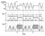
- FIG. 2 is a diagram showing waveforms of welding current, welding voltage, and welding wire feed speed in short-circuit welding, and droplet transfer states.
- FIG. 3 is a diagram showing waveforms of welding current, welding voltage, and welding wire feed speed in pulse welding, and droplet transfer states.
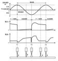
- FIG. 4 is a diagram showing waveforms of welding current, welding voltage, and welding wire feed speed in pulse mix welding.
- FIG. 5 is a side cross-sectional view showing a state in which arc welding is performed while performing a spiral weaving operation.
- FIG. 6 is a perspective view showing a state of arc welding while performing a spiral weaving operation.
- FIG. 1 is a schematic configuration diagram of an arc welding apparatus according to this embodiment.
- FIG. 2 is a diagram showing waveforms of welding current, welding voltage, and welding wire feed speed in short-circuit welding, and droplet transfer states.
- FIG. 3 is a diagram showing waveform
- FIG. 7 is a perspective view for explaining the timing of switching between short-circuit welding, pulse welding, and pulse mix welding.
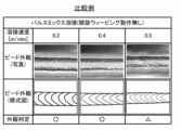
- FIG. 8 is a diagram for explaining the relationship between welding speed and bead appearance when pulse mix welding is performed without spiral weaving operation.
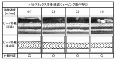
- FIG. 9 is a diagram showing the relationship between welding speed and bead appearance when pulse mix welding is performed during spiral weaving operation.
- FIG. 10 is a diagram showing the trajectory of the spiral weaving motion according to the modified example of the present embodiment.
- the arc welding apparatus 1 welds the object W to be welded by generating an arc 16 between the welding wire 15, which is a consumable electrode, and the object W to be welded.
- the arc welding device 1 has a welding unit 10 and a control section 30.
- the welding unit 10 has a welding torch 11 , a feed motor 12 , a robot 13 and a power converter 20 .
- the feed motor 12 feeds the welding wire 15 to the welding torch 11 at a predetermined feed speed.
- the robot 13 has multiple joints.
- a welding torch 11 is attached to the tip of the robot 13 .
- the robot 13 moves the position of the welding torch 11 with respect to the object W to be welded. Although details will be described later, the robot 13 causes the welding torch 11 to spiral weave along a spiral trajectory.
- the power conversion section 20 has a primary side rectification section 21 , a switching section 22 , a main transformer 23 , a secondary side rectification section 24 , a reactor 25 , a voltage detection section 26 and a current detection section 27 .
- the primary side rectifying section 21 rectifies and outputs the output of the input power supply 5 .
- the switching section 22 converts the DC output from the primary side rectifying section 21 into AC.
- a switching unit 22 controls a welding output consisting of a welding current and a welding voltage.
- the main transformer 23 converts the AC voltage output by the switching section 22 .
- the output of the main transformer 23 is output as welding output via the secondary side rectifier 24 and the reactor 25 .
- the secondary rectifier 24 rectifies the secondary output of the main transformer 23 .
- Voltage detector 26 detects welding voltage V.
- Current detector 27 detects welding current I. As shown in FIG.
- the control unit 30 includes a drive unit 31, a short-circuit welding control unit 33 that performs control for first welding including short-circuit welding, a pulse welding control unit 32 that performs control for second welding including pulse welding, A pulse mix welding control unit 34 that performs control for the third welding described later, a welding condition setting unit 35, a storage unit 36, a feed speed control unit 37, a first switching unit 38, and a second switching unit. 39 and a robot control unit 40 .
- the driving section 31 controls the switching section 22 .
- the pulse welding control section 32 performs control for pulse welding.
- the short-circuit welding control section 33 performs control for short-circuit welding.
- the pulse mix welding control section 34 performs control for the third welding.
- the third welding is a welding method in which short-circuit welding and pulse welding are alternately repeated multiple times each at a fixed number of times.
- the third welding is defined as "pulse mix welding", and this expression is used in the following description.
- the feeding of the welding wire 15 is basically forward and reverse feeding of the welding wire 15 in the case of short-circuit welding, and the feeding of the welding wire 15 in the case of pulse welding is fundamentally constant. preferably. However, it is not necessarily limited to this form. For example, as described later with reference to FIG. 3, the feeding speed of the welding wire 15 may be changed during pulse welding. Also, the welding wire 15 may be fed at a constant rate during short-circuit welding.
- the number of pulses during pulse welding and the number of short circuits during short circuit welding may be gradually changed.
- the number of pulses during pulse welding and the number of short circuits during short-circuit welding may be gradually changed.
- the number of pulses is 6 and the number of short circuits is 3, but the number of pulses may be changed to 3 and the number of short circuits may be changed to 6 and repeated multiple times. Note that the number of pulses and the number of short circuits are merely examples, and are not limited to these.
- the timing of gradually changing the number of pulses and the number of short circuits may be, for example, a predetermined welding distance, a predetermined welding time, or each preset teaching point.
- the welding condition setting unit 35 sets welding conditions including welding current and welding voltage. Specifically, the welding condition setting unit 35 controls the set welding current for welding, the set welding voltage for welding, the feeding speed of the welding wire 15, the type of shielding gas, the material of the welding wire 15, the welding wire 15 diameter, pulse welding period and pulse output frequency, short circuit welding period and short circuit output frequency, etc. are set.
- the shield gas is used differently depending on the welding wire material and application.
- argon gas (Ar) is used for welding aluminum alloys.
- MIG gas (98% Ar+2% O2) is used for welding stainless steel.
- MAG gas 80% Ar+20% CO2) is used for mild steel welding.
- Carbon dioxide gas (CO2) is used when welding of mild steel is cost-sensitive.
- the kind of shielding gas is just an example.
- a predetermined threshold value is stored in the storage unit 36 .
- the thresholds stored in the storage unit 36 are thresholds for welding parameters related to the heat input applied to the welding target W, such as welding current, welding voltage, and feed speed. Based on the output from the welding condition setting unit 35, the storage unit 36 outputs pre-stored welding operations, appropriate control values, the feeding speed of the welding wire 15, and the like.
- the feed speed control unit 37 controls the feed speed of the welding wire 15 according to the welding current set by the welding condition setting unit 35 .
- the feeding speed and the welding current are mutually correlated. More specifically, the average welding speed as a moving average (also referred to as feed rate) and the average welding current as an average current as a moving average (also referred to as set current) are correlated with each other.
- the first switching unit 38 outputs a signal for welding output of any one of the pulse welding control unit 32, the short-circuit welding control unit 33, and the pulse mix welding control unit 34 according to the output of the storage unit 36.
- the second switching unit 39 selects one of the feed speed outputs of the pulse welding control unit 32, the short-circuit welding control unit 33, and the pulse mix welding control unit 34 according to the output of the storage unit 36.
- the robot control unit 40 controls the operation of the robot 13.
- the robot control unit 40 moves the welding torch 11 along the welding direction of the object W to be welded by giving a current command to a motor (not shown) of each axis of the robot 13 .
- the arc welding apparatus 1 supplies a shielding gas from a gas supply port (not shown) to shield the welding location of the welding object W from the outside air while supplying current between the welding wire 15 and the welding object W.
- an arc 16 is generated between the welding wire 15 and the object W to be welded, and the heat of the arc 16 melts the tip of the welding wire 15 and part of the object W to be welded.
- the melted welding wire 15 becomes a droplet and drips onto the object W to be welded, forming a molten pool together with a part of the object W melted by the heat of the arc 16 .
- the welding torch 11 moves in the welding direction while spirally weaving the object W to be welded.
- a bead is formed on the object W to be welded as the welding torch 11 moves, and the object W to be welded is welded.
- the arc welding device 1 welds the welding target W while switching between short-circuit welding, pulse welding, and pulse-mix welding.
- Fig. 2 is a diagram showing waveforms of welding current, welding voltage, and welding wire feed speed in short-circuit welding, and a state of droplet transfer.
- the vertical axis indicates the welding current I, the welding voltage V, and the feed speed WF, and the horizontal axis indicates time.
- short-circuit welding there is a short-circuit period in which the welding wire 15 and the object W to be welded are in contact with each other and short-circuited, and an arc state in which an arc 16 is generated between the welding wire 15 and the object W to be welded.
- the welding current I is controlled so as to alternately transition to an arc period of .
- the welding wire 15 and the object W to be welded are short-circuited.
- An arc 16 is generated between the welding wire 15 and the object W to be welded during the arc period.
- a welding current of 100 A is applied to the welding wire 15, for example.
- P1 indicates the time point at which the short circuit is started, and in the short circuit period from P1 to P2, the short circuit current is gradually increased after outputting the short circuit initial current for a predetermined time from the time point P1.
- P2 indicates the point in time when the short circuit state ends and the arc state occurs.
- the first welding current of peak current is output immediately after the arc is generated, and then the welding current is shifted to the second welding current lower than the first welding current.
- From P2 to P3 is an arc period in which an arc 16 is generated between the welding wire 15 and the object W to be welded. During this arc period, an arc 16 is generated between the welding wire 15 and the object W to be welded, and the heat of the arc 16 forms a droplet at the tip of the welding wire 15 and partially melts the object W to be welded.
- P3 indicates the point in time when a short circuit occurs next to P1, and is in the same state as at point P1.
- the short-circuit welding alternately and periodically repeats the short-circuit period from P1 (P3) to P2 and the short-circuit period from P2 to P3.
- the welding wire is fed with a predetermined frequency and a predetermined velocity amplitude in a sinusoidal waveform having this as a basic waveform, and the forward feed and the reverse feed are alternately repeated multiple times. control.
- a short circuit occurs around time P1
- an arc occurs around time P2.
- the next short circuit occurs around the time point P3.
- FIG. 3 is a diagram showing the waveforms of the welding current, welding voltage, and welding wire feed speed in pulse welding, and the state of droplet transfer.
- the vertical axis indicates the welding current I, the welding voltage V, and the feed speed WF, and the horizontal axis indicates time.
- Pulse welding is welding in which peak current IP and base current IB are alternately repeated. In pulse welding, for example, a welding current of 200 A is applied to the welding wire 15 .
- the arc welding device 1 supplies welding current I and welding voltage V to the welding wire 15 .
- the pulse waveform of the welding current I includes a pulse rise period IPRT during which the welding current I transitions from the base current IB to the peak current IP, a peak current period IPT during which the welding current I is the peak current IP, and a peak current IP during the welding current I. to the base current IB, and a base current period IBT during which the welding current I is the base current IB.
- the feeding speed WF of the welding wire 15 is set to the first feeding speed WF1.
- the feed speed WF of the welding wire 15 is switched from the first feed speed WF1 to the second feed speed WF2.
- the arc welding apparatus 1 generates an arc 16 between the welding wire 15 and the object W to be welded, and the heat of the arc 16 forms a droplet at the tip of the welding wire 15 and partially melts the object W to be welded. melt.
- the droplets formed at the tip of the welding wire 15 move from the tip of the welding wire 15 to the object W to be welded by droplet transfer, forming a molten pool on the object W to be welded.
- the pulse period 1/PHz including one peak current IP and one base current IB is set as one pulse unit, and each pulse period In other words, welding is performed with one pulse and one drop in which one droplet transfers to the welding object W for each pulse of one peak current.
- the arc welding apparatus 1 changes the arc length H of the arc 16 with respect to the reference arc length H1 in the droplet separation state in which the droplet is transferred to the droplet. Specifically, the arc welding device 1 accelerates and decelerates the welding wire 15 during pulse welding.
- the feed speed WF of the welding wire 15 is switched from the first feed speed WF1 to the second feed speed WF2, and the welding wire 15 is accelerated.
- a short circuit between the welding wire 15 and the workpiece W is detected at time TP.
- the welding current is increased to current IS during the period from time TP to time NP.
- the feed speed WF of the welding wire 15 is switched from the second feed speed WF2 to the third feed speed WF3, and the welding wire 15 is decelerated.
- the welding current I changes from the current IS at time NP to the current IN (more than the current IS). (lower current).
- the welding current I is maintained at the second current IN during the period from time NP to time AP.
- the third feeding speed WF3 of the welding wire 15 is switched to the first feeding speed WF1.
- FIG. 3 shows an example in which the feeding speed WF of the welding wire 15 is changed during the pulse welding period. you can go In this case, the droplet transfer does not short-circuit the welding wire 15 and the welding object W, the arc 16 is continuously generated at the peak current and the base current, and the droplet formed at the tip of the welding wire 15 is , so that one pulse and one drop in which one droplet transfers to the welding object W for each pulse of one peak current is released in the air from the tip of the welding wire 15, and the welding object Go to W.
- Fig. 4 is a diagram showing waveforms of welding current, welding voltage, and welding wire feed speed in pulse mix welding.
- Pulse mix welding is welding in which a pulse welding period Tp in which pulse welding is performed and a short-circuit welding period Ts in which short-circuit welding is performed are alternately repeated multiple times.
- DC welding pulse mix welding in which DC short-circuit welding and DC pulse welding are combined will be described.
- the vertical axis indicates the welding current I, the welding voltage V, and the feed speed WF, and the horizontal axis indicates time.
- the welding current I flowing through the welding wire 15 is controlled so as to form a plurality of pulses in which the peak current Ip and the base current Ib are alternately repeated.
- the short-circuit welding period Ts in which short-circuit welding is performed one or more short-circuit periods S for short-circuiting the welding wire 15 and the welding object W, and one for generating an arc 16 between the welding wire 15 and the welding object W.
- the welding current I is controlled so as to shift alternately to the arc period A described above.
- the pulse welding period Tp and the short-circuit welding period Ts are alternately repeated such that the pulse welding period Tp follows the short-circuit welding period Ts, and the short-circuit welding period Ts follows the pulse welding period Tp.
- the pulse welding period Tp can be detected, for example, by detecting that the welding current I has changed from a value larger than a preset threshold value Is to a smaller value.
- the short-circuit welding period Ts can be detected, for example, by detecting that the welding voltage V has changed from a value larger than a preset threshold value Vs to a smaller value.
- the feed speed control unit 37 gives a control output to the feed motor 12 so that the feed speed WF of the welding wire 15 becomes a preset feed speed during the pulse welding period Tp and the short-circuit welding period Ts. Thereby, the welding wire 15 is fed at the constant third feeding speed WF3 during the pulse welding period Tp.
- the feeding speed WF of the welding wire 15 is changed according to a periodic waveform having a predetermined amplitude and period.
- the feed speed WF shown in FIG. 4 varies according to a sine wave as a periodic waveform.
- the short circuit is opened at the pulse start time Tps at which the number of short circuits preset by the welding condition setting unit 35 has been counted.
- the pulse start time Tps may be the time when the time preset by the welding condition setting unit 35 has elapsed.
- a pulse welding period Tp for performing pulse welding is started from the pulse start time Tps.
- the pulse mix welding control unit 34 starts the pulse welding period Tp and generates the first pulse among the plurality of pulses.
- the feed speed WF continues to change according to the periodic waveform during the short-circuit welding period Ts, and the welding wire 15 is fed at the pulse welding period Tp set in advance by the welding condition setting unit 35.
- the feeder 14 feeds the welding wire 15 at the third feed speed WF3. .
- the pulse mix welding control unit 34 After that, during the pulse welding period Tp, when the number of pulses set in advance by the welding condition setting unit 35 is counted, or when the time set in advance by the welding condition setting unit 35 elapses, the pulse mix welding control unit 34 After forming the last pulse, the welding current I is changed to a current I3 different from the base current Ib in the pulse.
- the feed speed WF is changed to the third feed in the pulse welding period Tp at the feed switching time Tvs when the welding current I is the current I3.
- the welding wire 15 is started to be fed in the forward direction and the reverse direction by changing the feeding speed WF3 according to the above-described periodic waveform.
- the pulse welding period Tp and the short-circuit welding period Ts are alternately repeated under the set conditions, and the welding wire 15 is fed at the optimum feeding speed WF in each mode at that time. I do.
- short-circuit welding, pulse welding, and pulse-mix welding are switched according to the heat capacity of the object W to be welded.
- the object W to be welded has a first member W1 and a second member W2.
- the plate thickness of the second member W2 is thicker than the plate thickness of the first member W1. Therefore, the heat capacity of the second member W2 is larger than the heat capacity of the first member W1.
- the first member W1 and the second member W2 are made of aluminum, for example.
- the first member W1 and the second member W2 are arranged in a state of facing each other.
- the position where the first member W1 and the second member W2 meet is the boundary position Wb between the first member W1 and the second member W2.
- the arc welding apparatus 1 performs welding while spirally weaving the welding torch 11 so as to alternately cross the boundary position Wb between the first member W1 and the second member W2 a plurality of times.
- the spiral weaving operation is an operation in which the welding torch 11 is moved along a spiral locus by moving the welding torch 11 along a circular locus in the welding direction.
- the welding wire 15 fed from the welding torch 11 is separated by the rotation radius r from the rotation center RC moving in the welding direction on the boundary position Wb between the first member W1 and the second member W2. In addition, it turns so as to revolve around the center of rotation RC at a predetermined rotation frequency.
- the size of the radius of gyration r shown in FIG. 6 is merely an example, and the present invention is not limited to this.
- the welding torch 11 may be moved to a position where the welding wire 15 can be supplied to the upper surface of the second member W2.
- the arc welding apparatus 1 switches the welding operation so that the first welding is performed on the first member W1 and the second welding is performed on the second member W2 during the spiral weaving operation.
- the first welding includes at least low heat input short-circuit welding.
- the second welding includes at least high heat input pulse welding.
- a third weld is performed in at least one of the first weld and the second weld.
- the third welding is pulse-mix welding in which short-circuit welding and pulse welding are alternately repeated multiple times each at a predetermined number of times.
- the arc welding start position on the boundary position Wb between the first member W1 and the second member W2 is 0°, and the arc is rotated clockwise around the rotation center RC in the welding direction. Welding shall be performed.
- the section from 20° to 160° is the first section 41
- the section from 160° to 190° is the second section 42
- the section from 190° to 350° is the third section 43
- the section from 350° to 20°. is the fourth segment 44 .
- the angle range of each section is just an example.
- the first switching unit 38 selects the output of the short-circuit welding control unit 33 suitable for the first member W1 having a small heat capacity in the first welding for welding the first member W1, and performs short-circuit welding. conduct.
- the first switching section 38 may select the output of the pulse mix welding control section 34 to perform pulse mix welding after the start of short-circuit welding.
- Pulse mix welding is a third welding in which a pulse welding period Tp in which pulse welding is performed and a short-circuit welding period Ts in which short-circuit welding is performed are alternately repeated multiple times. It is a weld with intermediate properties with low heat input. By performing pulse mix welding, it is possible to suppress sudden changes in heat input when the welding current is changed.
- the controller 30 controls the welding unit so that the proportion of the short-circuit welding period Ts in which short-circuit welding is performed during pulse mix welding is greater than the pulse welding period Tp in which pulse welding is performed. 10 operations. This allows pulse-mix welding to be performed under appropriate conditions. In the first welding, only short-circuit welding may be performed, and pulse mix welding may not be performed. Further, in pulse mix welding, the number of pulses during pulse welding and the number of short circuits during short circuit welding may be gradually changed.
- the second section 42 is a region spanning the first member W1 and the second member W2.
- the welding operation is performed such that the first welding in which at least short-circuit welding is performed on the first member W1 is performed, and the second welding in which at least pulse welding is performed on the second member W2 is performed. switch.
- the first switching unit 38 selects the output of the pulse mix welding control unit 34 and alternately repeats the pulse welding period Tp in which pulse welding is performed and the short-circuit welding period Ts in which short-circuit welding is performed multiple times. Pulse mix welding is performed as the third welding. By performing pulse mix welding, it is possible to suppress sudden changes in heat input when the welding current is changed.
- the control unit 30 determines that the proportion of the short-circuit welding period Ts in which short-circuit welding is performed during pulse mix welding is greater than the pulse welding period Tp in which pulse welding is performed. The operation of the welding unit 10 is controlled so that the Further, when pulse mix welding is performed in the second welding performed on the second member W2, the control unit 30 sets the ratio of the short circuit welding period Ts in which short circuit welding is performed during pulse mix welding to the pulse welding period in which pulse welding is performed. The operation of the welding unit 10 is controlled so as to be less than Tp.
- the proportion of the short-circuit welding period Ts in which short-circuit welding is performed during pulse mix welding is greater than when performed on the second member W2, and the second member When performing short-circuit welding on W2, the ratio of the short-circuit welding period Ts during which short-circuit welding is performed during pulse mix welding shall be smaller than when performing short-circuit welding on the first member W1.
- the proportion of the short-circuit welding period in which short-circuit welding with a small heat input is performed is increased, and welding is performed.
- the target region is the second member W2 having a larger heat capacity than the first member W1
- the proportion of the pulse welding period in which the heat input is larger than that of the short-circuit welding can be increased. can perform pulse-mix welding.
- pulse mix welding the number of pulses during pulse welding and the number of short circuits during short circuit welding may be gradually changed.
- the control unit 30 increases the welding current applied to the welding wire 15 before the welding torch 11 moving from the first member W1 to the second member W2 crosses the boundary position Wb. control 10.
- the welding current applied when welding torch 11 crosses boundary position Wb so that welding torch 11 moves from first member W1 to second member W2 is the welding current applied before welding torch 11 crosses boundary position Wb. greater than the current.
- the average welding current (set current ) is greater than the average welding current applied before the welding torch 11 crosses the boundary position Wb.
- a larger welding current is applied to the welding wire 15 in the second section 42 than the welding current applied to the welding wire 15 in the first section 41 .
- the average welding current and the feeding amount of the welding wire 15 are in a corresponding relationship.
- the amount of welding wire 15 fed may be increased compared to the first section 41 and the third section 43 to secure the amount of welding and welding may be performed.
- the first switching unit 38 selects the output of the pulse welding control unit 32 suitable for the second member W2 having a large heat capacity in the second welding for welding the second member W2, and performs pulse welding. conduct.
- the first switching unit 38 selects the output of the pulse mix welding control unit 34 to switch between the pulse welding period Tp during which pulse welding is performed and the short-circuit welding period Ts during which short-circuit welding is performed.
- Pulse mix welding may be performed as the third welding in which the steps are alternately repeated a plurality of times. By performing pulse mix welding, it is possible to suppress sudden changes in heat input when the welding current is changed.
- the control unit 30 sets the proportion of the pulse welding period Tp in which pulse welding is performed during pulse mix welding to be higher than the short-circuit welding period Ts in which short-circuit welding is performed.
- the operation of the welding unit 10 is controlled so that the This allows pulse-mix welding to be performed under appropriate conditions.
- in the second welding only pulse welding may be performed, and pulse mix welding may not be performed.
- the ratio of the pulse welding period Tp in which pulse welding is performed or the number of pulses during pulse welding, the ratio of the short-circuit welding period Ts in which short-circuit welding is performed, or the number of short circuits during short-circuit welding are gradually changed.
- the fourth section 44 is a region spanning the first member W1 and the second member W2.
- the welding operation is performed such that the first welding in which at least short-circuit welding is performed on the first member W1 is performed, and the second welding in which at least pulse welding is performed on the second member W2 is performed. switch.
- the first switching unit 38 selects the output of the pulse mix welding control unit 34 and alternately repeats the pulse welding period Tp in which pulse welding is performed and the short-circuit welding period Ts in which short-circuit welding is performed multiple times. Pulse mix welding is performed as the third welding. By performing pulse mix welding, it is possible to suppress sudden changes in heat input when the welding current is changed.
- the control unit 30 determines that the proportion of the short-circuit welding period Ts in which short-circuit welding is performed during pulse mix welding is greater than the pulse welding period Tp in which pulse welding is performed. The operation of the welding unit 10 is controlled so that the Further, when pulse mix welding is performed in the second welding performed on the second member W2, the control unit 30 sets the ratio of the short circuit welding period Ts in which short circuit welding is performed during pulse mix welding to the pulse welding period in which pulse welding is performed. The operation of the welding unit 10 is controlled so as to be less than Tp.
- the proportion of the short-circuit welding period Ts in which short-circuit welding is performed during pulse mix welding is greater than when performed on the second member W2, and the second member When performing short-circuit welding on W2, the ratio of the short-circuit welding period Ts during which short-circuit welding is performed during pulse mix welding shall be smaller than when performing short-circuit welding on the first member W1.
- the proportion of the short-circuit welding period in which short-circuit welding with a small heat input is performed is increased, and welding is performed.
- the proportion of the pulse welding period in which the heat input is larger than that of the short-circuit welding can be increased. can perform pulse-mix welding.
- pulse mix welding the number of pulses during pulse welding and the number of short circuits during short circuit welding may be gradually changed.
- the fourth section 44 before the welding torch 11 crosses the boundary position Wb between the first member W1 and the second member W2 from the second member W2 having a large heat capacity toward the first member W1 having a small heat capacity. , during pulse mix welding, gradually increase the ratio of the short-circuit welding period Ts during which short-circuit welding is performed with a lower heat input than pulse welding. In other words, the ratio of the number of short-circuits in pulse mix welding when crossing the boundary position Wb is greater than the ratio of the number of short-circuits in pulse mix welding before the welding torch 11 crosses the boundary position Wb. .
- the ratio of the number of short circuits when the welding torch 11 crosses the boundary position Wb is made larger than the ratio of the number of short circuits before the welding torch 11 crosses the boundary position Wb, and the boundary position is detected before crossing the boundary position Wb.
- short-circuit welding has a lower heat input than pulse welding.
- pulse mix welding in which a short-circuit welding period Ts for performing short-circuit welding and a pulse welding period Tp for performing pulse welding are alternately repeated multiple times at a predetermined rate, in the short-circuit welding period Ts, short-circuit welding with a low heat input has a cooling effect. . Therefore, heat input to the first member W1 is suppressed, and burn-through can be suppressed. Further, during the pulse welding period Tp, the arc 16 spreads and the width of the bead widens, and the droplets of the welding wire 15 are regularly detached and transferred to the bead formed by high heat input pulse welding, and the spatter is generated. less.
- the welding speed can be increased without reducing the welding quality due to burn-through.
- the relationship between the welding speed and the appearance of the bead will be described below with reference to FIGS. 8 and 9. FIG.
- FIG. 8 is a comparative example showing the relationship between welding speed and bead appearance when pulse mix welding is performed without spiral weaving operation.
- FIG. 8 shows a photograph showing the appearance of the bead, and a schematic diagram obtained by tracing the photograph of the appearance of the bead for easy visual understanding.
- the bead scales are continuously formed and the bead has a good appearance.
- the welding speed [m/min] is increased to 0.5 m/min, the formation of scales on the bead becomes non-uniform and the appearance of the bead deteriorates.
- the scales of the beads tend to extend gradually along the welding direction, and the boundaries between the beads tend to become thinner. Therefore, when only pulse-mix welding is performed without spiral weaving, the welding speed cannot be increased.
- FIG. 9 is a diagram showing the relationship between welding speed and bead appearance when pulse mix welding is performed while spiral weaving is performed.
- FIG. 9 shows a photograph showing the appearance of the bead, and a schematic diagram obtained by tracing the photograph of the appearance of the bead for easy visual understanding.
- the bead scale As shown in FIG. 9, even if the welding speed [m/min] is 0.7 m/min, 0.8 m/min, 0.9 m/min, or 1.0 m/min, the bead scale The mesh is continuously generated and the appearance of the weld bead is good. For example, even if the welding speed is increased, the scaly pattern of the beads does not change significantly, and the boundaries between the beads are clearly visible.
- the arc welding method using the arc welding apparatus 1 it is possible to improve the joint quality between members having different heat capacities. Specifically, at least short-circuit welding is performed on the first member W1 having a small heat capacity, and short-circuit welding with a low heat input is mainly performed compared to pulse welding, in other words, short-circuit welding that performs low heat input short-circuit welding. By increasing the ratio of the period Ts, burn-through of the first member W1 can be suppressed. Further, at least pulse welding is performed on the second member W2 having a large heat capacity, and high heat input pulse welding is mainly performed, in other words, the proportion of the pulse welding period Tp in which high heat input pulse welding is performed is increased. By doing so, it is possible to suppress the occurrence of insufficient penetration.
- the heat capacities are different by adjusting the welding conditions.
- Welding parameters welding current I, welding voltage V, feeding speed of the welding wire 15, thickness of the welding object W, etc.
- short-circuit welding, pulse welding, and pulse mix welding can be set.
- the arc welding apparatus 1 performs welding while spirally weaving the welding torch 11 along the welding direction.
- the welding wire 15 fed from the welding torch 11 is separated from the rotation center RC moving on the boundary position Wb between the first member W1 and the second member W2 by a rotation radius r and a predetermined Rotational movement is performed so as to revolve around the center of rotation RC at the rotation frequency.
- the distance r1 from the rotational position RC of the spiral locus to the spiral locus on the rear side in the welding direction is set to the forward side in the welding direction. is shorter than the distance r2 to the spiral trajectory.
- the distance r2 to the spiral locus on the front side in the welding direction is set to the same length as the rotation radius r, and the distance r1 to the spiral locus on the rear side in the welding direction is set shorter than the distance r2.
- the distance r1 may be the same length as the turning radius r, and the distance r2 may be longer than the distance r1.
- the thickness of the second member W2 is made thicker than the thickness of the first member W1 so as to have different heat capacities.
- the heat capacities may be different.
- the first member W1 and the second member W2 may have the same plate thickness, and the first member W1 may be made of aluminum and the second member W2 may be made of a mild steel material.
- the first member W1 has a small heat capacity
- the second member W2 has a large heat capacity
- the heat capacities are different.
- the second member W2 has a relatively large heat capacity compared to the first member W1.
- arc welding is performed while the first member W1 and the second member W2 are butted against each other, but the present invention is not limited to this form.
- the first member W1 and the second member W2 may be overlapped in the thickness direction, and the corners of the first member W1 and the second member W2 may be arc-welded.
- the heat capacity of the overlapped portion of the first member W1 and the second member W2 is larger than the heat capacity of the portion where the first member W1 and the second member W2 are not overlapped. Become. Therefore, the overlapped portion of the two plate materials is assumed to be the second member, and the non-overlapping portion is assumed to be the first member. do it.
- pulse mix welding is performed in the first welding and the second welding, but it is not limited to this form.
- the first welding may be short-circuit welding and the second welding may be pulse welding.
- the first welding may be short-circuit welding, and the second welding may be pulse-mix welding.
- the first welding may be pulse mix welding, and the second welding may be pulse welding.
- the welding torch 11 is made to spirally weave, but it is not limited to this form.
- the welding torch 11 is periodically oscillated left and right with respect to the boundary position Wb so as to alternately cross the boundary position Wb of the first member W1 and the second member W2 a plurality of times, and the weaving progresses in the welding progress direction.
- the welding torch 11 may be weaved in a zigzag manner. In this case, it is preferable that the weaving operation is performed to oscillate periodically to the left and right with respect to the boundary position Wb at a fine and acute angle.
- the radius r of the spiral trajectory during the spiral weaving operation is set to the same radius r on the first member W1 side and the second member W2 side, but may be set to different radii.
- the welding wire 15 is fed by periodically repeating forward feeding and reverse feeding of the welding wire 15, but it is not limited to this form.
- the welding wire 15 may be fed at a constant speed.
- the proportion of pulse welding may be increased in the forward direction in the welding direction from the center position of the spiral trajectory, while the proportion of short-circuit welding may be increased in the rearward direction in the welding direction. .
- a molten pool is formed by increasing the ratio of high heat input pulse welding in the front of the welding direction, and the molten pool is formed by increasing the ratio of low heat input short-circuit welding in the rear of the welding direction. is cooled.
- the present invention is extremely useful and has high industrial applicability because it can improve the quality of bonding between members with different heat capacities.
- Reference Signs List 1 arc welding device 10 welding unit 11 welding torch 13 robot 15 welding wire 30 control unit 32 pulse welding control unit 33 short-circuit welding control unit 34 pulse mix welding control unit 40 robot control unit W object to be welded W1 first member W2 second member Wb Boundary position
Landscapes
- Engineering & Computer Science (AREA)
- Physics & Mathematics (AREA)
- Plasma & Fusion (AREA)
- Mechanical Engineering (AREA)
- Arc Welding Control (AREA)
- Arc Welding In General (AREA)
Abstract
La capacité thermique d'un second élément W2 est supérieure à celle d'un premier élément W1. Le soudage est effectué en amenant un chalumeau de soudage (11) à effectuer un mouvement en zigzag de sorte à se déplacer sur toute l'étendue de l'emplacement limite Wb entre le premier élément W1 et le second élément W2. Pendant le mouvement en zigzag, un premier soudage est effectué sur le premier élément W1, et un second soudage est effectué sur le second élément W2. Lors du premier soudage, au moins un soudage par courts-circuits est effectué. Lors du second soudage, au moins un soudage par impulsions est effectué.
Applications Claiming Priority (2)
| Application Number | Priority Date | Filing Date | Title |
|---|---|---|---|
| JP2021-193499 | 2021-11-29 | ||
| JP2021193499 | 2021-11-29 |
Publications (1)
| Publication Number | Publication Date |
|---|---|
| WO2023095562A1 true WO2023095562A1 (fr) | 2023-06-01 |
Family
ID=86539357
Family Applications (1)
| Application Number | Title | Priority Date | Filing Date |
|---|---|---|---|
| PCT/JP2022/040631 WO2023095562A1 (fr) | 2021-11-29 | 2022-10-31 | Procédé de soudage à l'arc et dispositif de soudage à l'arc |
Country Status (1)
| Country | Link |
|---|---|
| WO (1) | WO2023095562A1 (fr) |
Citations (5)
| Publication number | Priority date | Publication date | Assignee | Title |
|---|---|---|---|---|
| JPH04158982A (ja) * | 1990-10-24 | 1992-06-02 | Nkk Corp | 溶接トーチのウィービング方法及び装置 |
| JP2012529991A (ja) * | 2009-06-18 | 2012-11-29 | フロニウス・インテルナツィオナール・ゲゼルシャフト・ミット・ベシュレンクテル・ハフツング | 溶接操作中に溶接プロセスを変更する方法および溶接操作前に熱入力する方法 |
| WO2016075871A1 (fr) * | 2014-11-11 | 2016-05-19 | パナソニックIpマネジメント株式会社 | Procédé de commande de soudage à l'arc |
| JP2016530106A (ja) * | 2013-09-16 | 2016-09-29 | イリノイ トゥール ワークス インコーポレイティド | 同期式回転アーク溶接方法およびシステム |
| WO2017038060A1 (fr) * | 2015-09-03 | 2017-03-09 | パナソニックIpマネジメント株式会社 | Procédé de soudage à l'arc et dispositif de soudage à l'arc |
-
2022
- 2022-10-31 WO PCT/JP2022/040631 patent/WO2023095562A1/fr unknown
Patent Citations (5)
| Publication number | Priority date | Publication date | Assignee | Title |
|---|---|---|---|---|
| JPH04158982A (ja) * | 1990-10-24 | 1992-06-02 | Nkk Corp | 溶接トーチのウィービング方法及び装置 |
| JP2012529991A (ja) * | 2009-06-18 | 2012-11-29 | フロニウス・インテルナツィオナール・ゲゼルシャフト・ミット・ベシュレンクテル・ハフツング | 溶接操作中に溶接プロセスを変更する方法および溶接操作前に熱入力する方法 |
| JP2016530106A (ja) * | 2013-09-16 | 2016-09-29 | イリノイ トゥール ワークス インコーポレイティド | 同期式回転アーク溶接方法およびシステム |
| WO2016075871A1 (fr) * | 2014-11-11 | 2016-05-19 | パナソニックIpマネジメント株式会社 | Procédé de commande de soudage à l'arc |
| WO2017038060A1 (fr) * | 2015-09-03 | 2017-03-09 | パナソニックIpマネジメント株式会社 | Procédé de soudage à l'arc et dispositif de soudage à l'arc |
Similar Documents
| Publication | Publication Date | Title |
|---|---|---|
| JP5278634B2 (ja) | アーク溶接制御方法およびアーク溶接装置 | |
| US9895760B2 (en) | Method and system to increase heat input to a weld during a short-circuit arc welding process | |
| JP6695030B2 (ja) | アーク溶接の制御方法 | |
| CA2282880C (fr) | Soudeuse a court-circuit | |
| US7397015B2 (en) | Metal cored electrode for open root pass welding | |
| US8937267B2 (en) | Method and system to increase heat input to a weld during a short-circuit arc welding process | |
| WO2013136643A1 (fr) | Procédé de commande de soudage à l'arc et dispositif de soudage à l'arc | |
| US20130213948A1 (en) | Method and system to increase heat input to a weld during a short-circuit arc welding process | |
| JP2015523217A (ja) | 調節可能な回転式アーク溶接方法およびシステム | |
| CN105880799B (zh) | 用于在短路电弧焊接过程中增加对焊接点的热量输入的方法和系统 | |
| JP2010264487A (ja) | アーク溶接方法 | |
| CN113165095B (zh) | 电弧焊接控制方法 | |
| JP7113329B2 (ja) | アーク溶接制御方法 | |
| WO2023095562A1 (fr) | Procédé de soudage à l'arc et dispositif de soudage à l'arc | |
| WO2017033978A1 (fr) | Procédé de soudage et dispositif de soudage à l'arc | |
| WO2023095623A1 (fr) | Procédé de soudage à l'arc et dispositif de soudage à l'arc | |
| JP2008080355A (ja) | プラズマミグ溶接方法 | |
| EP4180163A1 (fr) | Système de soudage ou de fabrication additive avec alimentation d'électrode discontinue | |
| WO2023042565A1 (fr) | Procédé de commande de soudage, dispositif de commande de soudage, alimentation électrique de soudage, système de soudage, programme, procédé de soudage et procédé de fabrication additive | |
| CN112004631B (zh) | 电弧焊接的控制方法 | |
| WO2023223798A1 (fr) | Procédé de commande de soudage à l'arc avec électrode métallique en atmosphère de gaz, procédé de définition de condition de soudage, dispositif de commande de soudage, alimentation électrique de soudage, système de soudage, programme, procédé de soudage à l'arc avec électrode métallique en atmosphère de gaz, et procédé de fabrication additive | |
| JP2001225168A (ja) | 消耗電極ガスシールドアーク溶接方法 | |
| CN114654048A (zh) | 混合射出式和流式脉冲焊接 |
Legal Events
| Date | Code | Title | Description |
|---|---|---|---|
| 121 | Ep: the epo has been informed by wipo that ep was designated in this application |
Ref document number: 22898347 Country of ref document: EP Kind code of ref document: A1 |
|
| ENP | Entry into the national phase |
Ref document number: 2023563583 Country of ref document: JP Kind code of ref document: A |