WO2023095205A1 - Nébuliseur - Google Patents
Nébuliseur Download PDFInfo
- Publication number
- WO2023095205A1 WO2023095205A1 PCT/JP2021/042981 JP2021042981W WO2023095205A1 WO 2023095205 A1 WO2023095205 A1 WO 2023095205A1 JP 2021042981 W JP2021042981 W JP 2021042981W WO 2023095205 A1 WO2023095205 A1 WO 2023095205A1
- Authority
- WO
- WIPO (PCT)
- Prior art keywords
- forming plate
- channel
- liquid
- flow path
- hole
- Prior art date
Links
- 239000006199 nebulizer Substances 0.000 title claims abstract description 146
- 239000007788 liquid Substances 0.000 claims abstract description 395
- 239000012530 fluid Substances 0.000 claims abstract description 4
- 125000006850 spacer group Chemical group 0.000 claims description 40
- 230000002093 peripheral effect Effects 0.000 claims description 14
- 230000004308 accommodation Effects 0.000 claims description 13
- 230000000149 penetrating effect Effects 0.000 claims description 8
- 238000002347 injection Methods 0.000 abstract 3
- 239000007924 injection Substances 0.000 abstract 3
- 239000007789 gas Substances 0.000 description 239
- 238000010008 shearing Methods 0.000 description 11
- 239000007921 spray Substances 0.000 description 9
- 238000004458 analytical method Methods 0.000 description 7
- 239000007787 solid Substances 0.000 description 7
- 239000011521 glass Substances 0.000 description 5
- 239000000463 material Substances 0.000 description 5
- 230000005284 excitation Effects 0.000 description 4
- 229910052751 metal Inorganic materials 0.000 description 4
- 239000002184 metal Substances 0.000 description 4
- 239000003960 organic solvent Substances 0.000 description 4
- 239000004813 Perfluoroalkoxy alkane Substances 0.000 description 3
- 239000007864 aqueous solution Substances 0.000 description 3
- 238000000889 atomisation Methods 0.000 description 3
- 238000006243 chemical reaction Methods 0.000 description 3
- 238000004140 cleaning Methods 0.000 description 3
- 230000005484 gravity Effects 0.000 description 3
- 238000000034 method Methods 0.000 description 3
- 239000000203 mixture Substances 0.000 description 3
- 229920011301 perfluoro alkoxyl alkane Polymers 0.000 description 3
- 229920005989 resin Polymers 0.000 description 3
- 239000011347 resin Substances 0.000 description 3
- 238000005406 washing Methods 0.000 description 3
- OKTJSMMVPCPJKN-UHFFFAOYSA-N Carbon Chemical compound [C] OKTJSMMVPCPJKN-UHFFFAOYSA-N 0.000 description 2
- 239000004696 Poly ether ether ketone Substances 0.000 description 2
- 239000004734 Polyphenylene sulfide Substances 0.000 description 2
- 239000002253 acid Substances 0.000 description 2
- 238000000149 argon plasma sintering Methods 0.000 description 2
- 229910052799 carbon Inorganic materials 0.000 description 2
- 239000000919 ceramic Substances 0.000 description 2
- 230000000694 effects Effects 0.000 description 2
- 238000004811 liquid chromatography Methods 0.000 description 2
- 150000002739 metals Chemical class 0.000 description 2
- 238000002663 nebulization Methods 0.000 description 2
- BASFCYQUMIYNBI-UHFFFAOYSA-N platinum Chemical compound [Pt] BASFCYQUMIYNBI-UHFFFAOYSA-N 0.000 description 2
- 229920002530 polyetherether ketone Polymers 0.000 description 2
- 229920000069 polyphenylene sulfide Polymers 0.000 description 2
- 229920001296 polysiloxane Polymers 0.000 description 2
- 229920001343 polytetrafluoroethylene Polymers 0.000 description 2
- 239000004810 polytetrafluoroethylene Substances 0.000 description 2
- 239000002244 precipitate Substances 0.000 description 2
- 239000000047 product Substances 0.000 description 2
- 238000007789 sealing Methods 0.000 description 2
- 239000000126 substance Substances 0.000 description 2
- 239000004642 Polyimide Substances 0.000 description 1
- 150000007513 acids Chemical class 0.000 description 1
- 239000000853 adhesive Substances 0.000 description 1
- 230000001070 adhesive effect Effects 0.000 description 1
- 238000013459 approach Methods 0.000 description 1
- 238000001479 atomic absorption spectroscopy Methods 0.000 description 1
- 238000001391 atomic fluorescence spectroscopy Methods 0.000 description 1
- 238000001675 atomic spectrum Methods 0.000 description 1
- 239000012159 carrier gas Substances 0.000 description 1
- 229920001940 conductive polymer Polymers 0.000 description 1
- PCHJSUWPFVWCPO-UHFFFAOYSA-N gold Chemical compound [Au] PCHJSUWPFVWCPO-UHFFFAOYSA-N 0.000 description 1
- 229910052737 gold Inorganic materials 0.000 description 1
- 239000010931 gold Substances 0.000 description 1
- 230000002209 hydrophobic effect Effects 0.000 description 1
- 238000001746 injection moulding Methods 0.000 description 1
- 229910052741 iridium Inorganic materials 0.000 description 1
- GKOZUEZYRPOHIO-UHFFFAOYSA-N iridium atom Chemical compound [Ir] GKOZUEZYRPOHIO-UHFFFAOYSA-N 0.000 description 1
- 238000004895 liquid chromatography mass spectrometry Methods 0.000 description 1
- 238000003754 machining Methods 0.000 description 1
- 238000004519 manufacturing process Methods 0.000 description 1
- 238000004949 mass spectrometry Methods 0.000 description 1
- 238000005259 measurement Methods 0.000 description 1
- 238000006386 neutralization reaction Methods 0.000 description 1
- 238000005191 phase separation Methods 0.000 description 1
- 238000001637 plasma atomic emission spectroscopy Methods 0.000 description 1
- 238000000918 plasma mass spectrometry Methods 0.000 description 1
- 239000004033 plastic Substances 0.000 description 1
- 229910052697 platinum Inorganic materials 0.000 description 1
- 229920001721 polyimide Polymers 0.000 description 1
- -1 polytetrafluoroethylene Polymers 0.000 description 1
- 238000006479 redox reaction Methods 0.000 description 1
- 239000000243 solution Substances 0.000 description 1
- 238000005507 spraying Methods 0.000 description 1
- 238000003892 spreading Methods 0.000 description 1
Images


Classifications
-
- B—PERFORMING OPERATIONS; TRANSPORTING
- B05—SPRAYING OR ATOMISING IN GENERAL; APPLYING FLUENT MATERIALS TO SURFACES, IN GENERAL
- B05B—SPRAYING APPARATUS; ATOMISING APPARATUS; NOZZLES
- B05B7/00—Spraying apparatus for discharge of liquids or other fluent materials from two or more sources, e.g. of liquid and air, of powder and gas
- B05B7/02—Spray pistols; Apparatus for discharge
- B05B7/04—Spray pistols; Apparatus for discharge with arrangements for mixing liquids or other fluent materials before discharge
-
- G—PHYSICS
- G01—MEASURING; TESTING
- G01N—INVESTIGATING OR ANALYSING MATERIALS BY DETERMINING THEIR CHEMICAL OR PHYSICAL PROPERTIES
- G01N1/00—Sampling; Preparing specimens for investigation
- G01N1/28—Preparing specimens for investigation including physical details of (bio-)chemical methods covered elsewhere, e.g. G01N33/50, C12Q
-
- G—PHYSICS
- G01—MEASURING; TESTING
- G01N—INVESTIGATING OR ANALYSING MATERIALS BY DETERMINING THEIR CHEMICAL OR PHYSICAL PROPERTIES
- G01N27/00—Investigating or analysing materials by the use of electric, electrochemical, or magnetic means
- G01N27/62—Investigating or analysing materials by the use of electric, electrochemical, or magnetic means by investigating the ionisation of gases, e.g. aerosols; by investigating electric discharges, e.g. emission of cathode
-
- H—ELECTRICITY
- H01—ELECTRIC ELEMENTS
- H01J—ELECTRIC DISCHARGE TUBES OR DISCHARGE LAMPS
- H01J49/00—Particle spectrometers or separator tubes
- H01J49/02—Details
- H01J49/04—Arrangements for introducing or extracting samples to be analysed, e.g. vacuum locks; Arrangements for external adjustment of electron- or ion-optical components
Definitions
- the present invention relates to nebulizers. More particularly, the present invention relates to nebulizers that atomize liquid samples for introduction into analytical instruments.
- Plasma emission spectrometry, atomic absorption spectrometry, and atomic fluorescence spectrometry are known as atomic spectrum analysis methods.
- plasma mass spectrometry, liquid chromatography mass spectrometry, and the like are known as mass spectrometry.
- liquid chromatography using light scattering detectors is also known.
- analyzers used for these analytical methods sample droplets obtained by atomizing a liquid sample with a nebulizer are introduced into an excitation/ionization source or the like of the analyzer.
- Nebulizers are roughly classified into pneumatic nebulizers and ultrasonic nebulizers. Among them, pneumatic nebulizers are often used in atomic spectrometers and mass spectrometers because they are small and simple. Pneumatic nebulizers are further subdivided into concentric type, cross flow type, entrained type, Babington nebulizer, and parallel path type (Burgener nebulizer).
- pneumatic nebulizers There are many types of pneumatic nebulizers, but the atomization principle is common to all types. That is, a high-speed gas stream is made to collide with a liquid sample, and the liquid sample is made into fine droplets by the shearing force of the high-speed gas.
- the difference between the types is mainly due to the difference in the structure of the flow path through which the gas and liquid sample flow up to the position where the high-speed gas stream collides with the liquid sample and ejects fine droplets.
- a coaxial nebulizer has two tubes arranged coaxially, with a liquid sample flowing through the inner tube and a gas flowing between the outer tube and the inner tube. In some cases, the gas is flowed through the inner tube and the liquid sample is flowed between the outer tube and the inner tube.
- Patent Document 1 discloses that a gap between the outer tube and the inner tube is adjusted by crushing the tip of the outer tube by screwing a nut surrounding the outer tube, and the inner tube and the outer tube are adjusted by moving the screw member back and forth. It is disclosed to adjust the tip position relative to the .
- a cross-flow nebulizer has a tube for liquid samples and a tube for gas that are arranged at right angles.
- a mixing type nebulizer mixes a liquid sample and a gas at a position in front of an ejection port, and then ejects the mixture from the ejection port.
- Patent Document 2 discloses a nebulizer having a liquid channel and a gas channel inside a glass tube, and a V groove formed at the tip of the glass tube from the liquid outlet to the gas outlet. ing. A liquid sample discharged from the liquid outlet flows down the V-shaped groove by gravity and is atomized at the gas outlet.
- a parallel path type nebulizer has a liquid channel and a gas channel arranged in parallel, and the liquid outlet and the gas outlet are adjacent to each other.
- Patent Documents 3 and 4 disclose a nebulizer in which a sample channel and a gas channel are formed in parallel inside a rod-shaped body, and a liquid outlet and a gas outlet are adjacent to each other at the tip of the rod-shaped body.
- Parallel path nebulizers do not require a flow path connecting the liquid and gas outlets.
- Patent Document 5 discloses that a liquid channel and a gas channel are formed in parallel inside a rod-shaped main body, and a mesh screen is provided at the tip of the main body so as to span the liquid outlet and the gas outlet. nebulizer is disclosed. The liquid sample discharged from the liquid outlet travels through the mesh screen to the gas outlet and is atomized. Such a form of nebulizer is called a Hildebrand nebulizer.
- a long and narrow capillary tube is used as the inner tube for the coaxial nebulizer. Therefore, (1) the inner tube is easily damaged, (2) the tip of the inner tube vibrates due to high-speed gas flow, and the generation rate of fine droplets tends to fluctuate. There is a problem that deposits tend to clog.
- Patent Document 1 the reproducibility of the relative relationship between the gap between the outer tube and the inner tube and the tip position of the inner tube and the outer tube differs from product to product, There is the problem of volatility.
- the Babington nebulizer does not have the above problems (1) to (3), but (4) the position of the nebulizer is limited because the liquid sample flows down by gravity, and (5) the material of the nebulizer is hydrophobic plastic. A problem with the material is that the sample liquid film is difficult to spread and may not pass over the gas outlet.
- Parallel-path nebulizers do not have the above problems (1) to (5), but (6) they do not have the effect of sucking up liquid samples, so they require liquid-feeding pumps. Problems are that they tend to be less reproducible and sample droplets can be larger, so they tend to be less sensitive than concentric nebulizers.
- the Hildebrand nebulizer does not have the above problems (1) to (5), it has the problem of (8) that the liquid sample tends to remain on the mesh screen and it takes time to wash, reducing analysis throughput.
- the root cause of the problem of the coaxial nebulizer is considered to be the use of a long and narrow capillary tube as the inner tube.
- the flow path connecting the liquid outlet and the gas outlet is a non-restricted space (V-shaped groove in the Babington type, liquid outlet and gas outlet in the parallel-path type) that is not surrounded by walls.
- the surface between and the Hildebrand type mesh screen has the advantage of suppressing clogging such as suspended matter.
- the non-restricted space channel causes problems such as the limited position of the nebulizer, the need for a liquid feed pump because it has no effect of sucking up the liquid sample, and the decrease in analysis throughput. ing.
- problems common to all types of nebulizers include: (9) individual nebulizers are limited to a single function; (10) If the nebulizer is damaged, the parts cannot be replaced and the entire nebulizer must be replaced.
- the object of the present invention is to provide a multi-functional nebulizer that can handle liquid samples with various characteristics and flow rates.
- a first aspect of the nebulizer comprises a base having a front surface and a rear surface, a tip joined to the front surface of the base, and a liquid inlet opening to the rear surface and a liquid outlet opening to the front surface. and a base gas flow channel communicating between the rear open gas inlet and the front open gas outlet; It is composed of a channel forming plate, and the tip part is formed in one of the channel forming plates or formed by stacking a plurality of the channel forming plates, and contains a mixed fluid of gas and droplets. Having a jet hole for jetting, a tip liquid channel for guiding the liquid discharged from the liquid outlet to the jet hole, and a tip gas channel for guiding the gas discharged from the gas outlet to the jet hole.
- a second aspect of the nebulizer is characterized in that, in the first aspect, the passage forming plate has a through hole that communicates between the rear surface and the front surface and forms the tip portion liquid passage or the tip portion gas passage. and A third aspect of the nebulizer is characterized in that, in the second aspect, the channel forming plate has grooves formed on the rear surface or the front surface thereof to form the tip portion liquid channel or the tip portion gas channel. .
- a fourth aspect of the nebulizer is characterized in that, in the second aspect, the passage forming plate has a concave portion formed on the rear surface or the front surface and forming the tip portion liquid passage or the tip portion gas passage. .
- a fifth aspect of the nebulizer is characterized in that, in the second aspect, the channel forming plate has a nozzle projecting from the front surface and having the through hole penetrating through the center.
- a sixth aspect of the nebulizer is characterized in that, in the second aspect, the passage forming plate has a nozzle accommodation hole that forms the cylindrical tip gas passage between the nozzle and the accommodated nozzle.
- the tip portion in the first aspect, has a first through hole formed at a position corresponding to the liquid outlet and a second through hole formed at a position corresponding to the gas outlet.
- the tip portion has a groove formed on the rear surface from a position corresponding to the liquid outlet to a position corresponding to the gas outlet, and a position corresponding to the gas outlet.
- a ninth aspect of the nebulizer is the first aspect, wherein the tip portion has a groove formed on the rear surface from a position corresponding to the liquid outlet to a position near the position corresponding to the gas outlet, and a groove formed at the position near the position corresponding to the gas outlet. and a second through hole formed at a position corresponding to the gas outlet, and the opening of the first through hole and the opening of the second through hole are adjacent to each other on the front surface.
- a tenth aspect of the nebulizer is the first aspect, wherein the tip portion has a groove formed on the rear surface from a position corresponding to the liquid outlet to a position near the position corresponding to the gas outlet, and a groove formed at the position near the position corresponding to the gas outlet.
- a fifth mold flow passage forming plate having recesses formed in regions thereof; and a second mold flow passage forming plate having the ejection holes formed at positions corresponding to the gas outlets, wherein the fifth mold
- the channel-forming plate and the second-type channel-forming plate are joined in this order to the front surface of the base, and the grooves of the fifth-type channel-forming plate are combined with the front surface of the base.
- the tip portion corresponds to a nozzle projecting from the front surface at a position corresponding to the liquid outlet, a first through hole penetrating the center of the nozzle, and the gas outlet.
- a sixth type flow passage forming plate having a second through hole formed at a position corresponding to the liquid outlet; a seventh-type channel-forming plate having holes, wherein the sixth-type channel-forming plate and the seventh-type channel-forming plate are bonded in this order to the front surface of the base;
- the nozzles of the 6-type flow passage forming plate are housed in the nozzle housing holes of the 7th-type flow passage forming plate to form the cylindrical tip gas flow passages.
- a twelfth aspect of the nebulizer is characterized in that, in the eleventh aspect, the tip portion is provided with a spacer plate sandwiched between the sixth-type channel forming plate and the seventh-type channel forming plate.
- the base portion has a second base portion liquid channel that communicates a second liquid inlet opening on the rear surface and a second liquid outlet opening on the front surface.
- the tip portion has a first through hole formed at a position corresponding to the liquid outlet, a second through hole formed at a position corresponding to the second liquid outlet, and a rear surface corresponding to the gas outlet.
- a second recess formed in a circular area centered on the center and a third recess formed in a circular area centered on the opening of the fourth through hole connected to the opening of the second through hole on the front surface an eighth mold flow path forming plate, a first ejection hole formed at a position corresponding to the third through hole, and a second ejection hole formed at a position corresponding to the fourth through hole and a 9-type channel forming plate, wherein the 8-type channel forming plate and the 9-type channel forming plate are joined in this order to the front surface of the base portion, and the 8-type channel forming plate
- the first recess of the forming plate is combined with the front surface of the base to form the tip gas channel, and the peripheral edge of the second recess of the eighth mold channel forming plate is the ninth mold flow channel.
- the base has a second base gas flow path that communicates between a second gas inlet opening on the rear surface and a second gas outlet opening on the front surface.
- the tip portion includes a first nozzle projecting from the front surface at a position corresponding to the liquid outlet, a first through hole penetrating the center of the first nozzle, and a first nozzle formed at a position corresponding to the gas outlet.
- a tenth type flow passage forming plate having two through holes and a third through hole formed at a position corresponding to the second gas outlet; and a second nozzle projecting from the front surface at a position corresponding to the liquid outlet.
- a first nozzle housing hole on the rear side and the ejection hole on the front side which form a through hole passing through the center of the second nozzle; and a fourth through hole formed at a position corresponding to the second gas outlet.
- a twelfth type flow path forming plate having a second nozzle accommodation hole formed at a position corresponding to the liquid outlet, the tenth type flow path forming plate,
- the eleventh type flow path forming plate and the twelfth type flow path forming plate are joined in this order to the front surface of the base portion, and the first nozzle of the tenth type flow path forming plate is connected to the eleventh type flow path forming plate. It is accommodated in the first nozzle accommodation hole of the mold channel forming plate to form a cylindrical first tip gas channel, and the second nozzle of the eleventh mold channel forming plate accommodates the twelfth mold channel.
- the tip portion comprises a first spacer plate sandwiched between the tenth mold channel forming plate and the eleventh mold channel forming plate, and the eleventh mold channel forming plate. a second spacer plate sandwiched between the channel forming plate and the twelfth type channel forming plate.
- the base portion has a plurality of the base portion liquid channels formed on a circumference centered on the base portion gas channel, and the tip portion has a rear surface.
- a third mold flow path forming plate having grooves formed in a radial direction from a position corresponding to the gas outlet and the ejection holes formed at a position corresponding to the gas outlet in the third mold flow
- a channel-forming plate is joined to the front surface of the base, and the groove in the third-type channel-forming plate connects with one of the plurality of base liquid channels to form the tip liquid flow channel.
- the base portion has a plurality of base portion liquid channels formed at equal angular intervals on a circumference around the base portion gas channel, and the tip end The portion has a first groove and a second groove radially formed from a position corresponding to the gas outlet on the rear surface, and the ejection hole formed at a position corresponding to the gas outlet.
- the base portion has a plurality of base portion liquid channels with different inner diameters formed on a circumference around the base portion gas channel
- the tip portion is a fourteenth type flow passage forming plate having a plurality of grooves with different widths radially formed from positions corresponding to the gas outlets on the rear surface, and the ejection holes formed at positions corresponding to the gas outlets.
- a nineteenth aspect of the nebulizer is characterized in that, in any one of the first to eighteenth aspects, it comprises a cylindrical body to which the base portion and the tip portion are attached to the tip.
- the tip portion liquid channel and the tip portion gas channel by changing the combination of the channel forming plates that configure the tip portion. Therefore, it becomes a nebulizer having atomization performance suitable for liquid samples with various characteristics and flow rates. Also, even if the flow path is clogged with suspended solids, the flow path forming plate can be removed to facilitate cleaning. Furthermore, even if some parts are damaged, the functions can be restored by replacing the parts.
- a coaxial flow path can be formed by housing the nozzle in the nozzle housing hole.
- a coaxial flow path can be formed by housing the nozzle in the nozzle housing hole.
- the tip portion liquid channel is a restricted space channel surrounded by walls, the posture of the nebulizer is not restricted, and the liquid sample can be sucked up.
- the flow path forming plate can be removed and washed easily.
- the tip portion liquid channel is a restricted space channel surrounded by walls, the posture of the nebulizer is not limited, and the liquid sample can be sucked up.
- the flow path forming plate can be removed and washed easily.
- fine droplets can be ejected by shearing the liquid sample with adjacent gas flows.
- the liquid sample can be atomized by spreading the liquid sample in the circular recess to form a liquid film and passing it over the gas outlet.
- the nebulizer has the same function as the coaxial nebulizer.
- the thickness or the number of spacer plates by changing the thickness or the number of spacer plates, it is possible to adjust the relative relationship between the gap between the nozzle and the nozzle housing hole and the tip position between the nozzle and the nozzle housing hole.
- two types of liquid samples can be simultaneously sprayed from separate ejection holes. Therefore, two types of liquid samples can be sprayed without being mixed.
- the gas can flow around the sample droplet ejected from the ejection hole. This makes it possible to make the sample droplets even finer and to control the direction of spraying.
- the gap between the first nozzle and the first nozzle receiving hole and the tip position between the first nozzle and the first nozzle receiving hole You can adjust the relative relationship between Also, by changing the thickness or the number of the second spacer plates, the relative relationship between the gap between the second nozzle and the second nozzle housing hole and the tip position between the second nozzle and the second nozzle housing hole can be changed. Adjustable. According to the sixteenth aspect, since one of the plurality of base liquid channels is selected and connected to the ejection hole, even if one base liquid channel is clogged or damaged, the other base liquid channels are You can continue using the nebulizer by switching to the partial liquid flow path.
- the seventeenth aspect two types of liquid samples can be mixed and sprayed immediately before the ejection port. Therefore, it is possible to stably spray a combination of liquid samples that would be difficult to spray if mixed, or a combination of liquid samples that cannot be mixed.
- the width of the liquid channel can be selected according to liquid samples with various flow rates. Therefore, one nebulizer can handle a wide range of flow rates.
- the outer shape of the cylindrical body is adapted to an existing nebulizer, it can be used in exchange for an existing nebulizer.
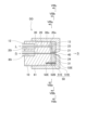
- FIG. 1 is a longitudinal sectional view of a nebulizer according to a first embodiment
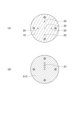
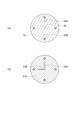
- FIG. FIG. (A) is an end view taken along line IIa-IIa in FIG.
- FIG. (B) is an end view taken along line IIb-IIb in FIG.
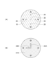
- FIG. (C) is an end view taken along line IIc-IIc in FIG.
- FIG. 4 is an end view taken along line IV-IV in FIG. 3
- FIG. 10 is a vertical cross-sectional view of a nebulizer according to a third embodiment
- FIG. (A) is an end view taken along line VIa-VIa in FIG. FIG.
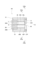
- FIG. (B) is an end view taken along line VIb-VIb in FIG. It is a longitudinal cross-sectional view of a nebulizer according to a fourth embodiment.
- FIG. (A) is an end view taken along line VIIIa-VIIIa in FIG.
- FIG. (B) is an end view taken along line VIIIb-VIIIb in FIG.
- FIG. (C) is an end view taken along line VIIIc-VIIIc in FIG. It is a longitudinal section of a nebulizer concerning a 5th embodiment.
- FIG. 10 is an end view taken along line XX in FIG. 9;
- FIG. 10 is a vertical cross-sectional view of a nebulizer according to another embodiment;
- FIG. 11 is a vertical cross-sectional view of a nebulizer according to a sixth embodiment
- FIG. (A) is an end view taken along line XIIIa-XIIIa in FIG.
- FIG. (B) is an end view taken along line XIIIb--XIIIb in FIG.
- FIG. (C) is an end view taken along line XIIIc-XIIIc in FIG.
- FIG. 11 is a vertical cross-sectional view of a nebulizer according to a seventh embodiment
- FIG. (A) is an end view taken along line XVa-XVa in FIG.
- FIG. (B) is an end view taken along line XVb-XVb in FIG.
- FIG. 11 is a vertical cross-sectional view of a nebulizer according to an eighth embodiment
- FIG. (A) is an end view taken along line XVIIa-XVIIa in FIG.
- FIG. (B) is an end view taken along line XVIIb-XVIIb in FIG.
- FIG. 20 is a vertical cross-sectional view of a nebulizer according to a ninth embodiment
- FIG. (A) is an end view taken along line XIXa-XIXa in FIG.
- FIG. (B) is an end view taken along line XIXb-XIXb in FIG.
- FIG. 20 is a vertical cross-sectional view of a nebulizer according to a tenth embodiment
- FIG. 20 is a vertical cross-sectional view of a nebulizer according to an eleventh embodiment
- a nebulizer according to a first embodiment of the present invention is used to atomize a liquid sample to obtain sample droplets.
- a sample droplet is introduced into an excitation/ionization source or the like of an analysis device and subjected to analysis.
- the excitation/ionization source or the like is, for example, a plasma in an ICP analyzer, generated by a plasma torch.
- a sample droplet is introduced into a light scattering detector. Such detectors are also included in excitation/ionization sources and the like.
- the nebulizer AA of this embodiment has a base portion 10 and a tip portion 50 .
- the base portion 10 is a rod-shaped member having a circular cross section.
- One end face of the base portion 10 is called a rear face 12 and the other end face is called a front face 13 .
- the posterior surface 12 and the anterior surface 13 are planes perpendicular to the central axis of the base 10 .
- Two channels are formed in the base 10 along the axial direction: a base liquid channel 20 and a base gas channel 30 .
- the base liquid channel 20 has a liquid inlet 20i opening to the rear surface 12 and a liquid outlet 20o opening to the front surface 13.
- a base liquid channel 20 communicates between a liquid inlet 20i and a liquid outlet 20o.
- the base gas channel 30 has a gas inlet 30i opening at the rear surface 12 and a gas outlet 30o opening at the front surface 13.
- a base gas channel 30 communicates between a gas inlet 30i and a gas outlet 30o.
- the base liquid channel 20 and the base gas channel 30 are arranged in parallel at adjacent positions.
- the base portion gas flow path 30 is arranged along the central axis of the base portion 10 .
- the base portion liquid channel 20 is arranged at a position eccentric from the central axis of the base portion 10 .
- the inner diameters of the base liquid channel 20 and the base gas channel 30 can be set arbitrarily. For example, if the inner diameter of the base liquid channel 20 is set to 0.3 mm to 1.0 mm, clogging with suspended solids and the like can be suppressed.
- the base gas channel 30 may be narrower than the base liquid channel 20 .
- the inner diameter of the base gas channel 30 is, for example, 0.1 mm to 1.0 mm.
- the inner diameters of the base liquid channel 20 and the base gas channel 30 may be the same. In this case, the usage of the two channels can be interchanged. That is, the central channel may be used as the base liquid channel and the eccentric channel may be used as the base gas channel.
- the tip portion 50 is joined to the front surface 13 of the base portion 10 .
- the tip 50 consists of one or more channel forming plates.
- the tip portion 50 consists of a first mold channel forming plate 51A and a second mold channel forming plate 51B. Both the first mold channel forming plate 51A and the second mold channel forming plate 51B are disk-shaped members.
- the first mold channel forming plate 51A and the second mold channel forming plate 51B are joined to the front surface 13 of the base portion 10 in this order. That is, the first mold flow path forming plate 51A is provided so that the rear surface 52A contacts the front surface 13 of the base portion 10. As shown in FIG.
- the second mold channel forming plate 51B is provided so that the rear surface 52B contacts the front surface 53A of the first mold channel forming plate 51A.
- the second type channel forming plate 51B is arranged at the forefront of the nebulizer AA.
- the tip portion 50 is formed with a tip portion liquid flow channel, a tip portion gas flow channel, and ejection holes.
- the ejection hole is a hole for ejecting a mixed fluid of gas and liquid sample droplets.
- the tip liquid channel is a channel that guides the liquid sample discharged from the liquid outlet 20o to the ejection hole.
- the tip portion gas channel is a channel that guides the gas discharged from the gas outlet 30o to the ejection hole.
- the first type flow path forming plate 51A has a first through hole 21 and a second through hole 31.
- Both the first through-hole 21 and the second through-hole 31 are holes that communicate between the rear surface 52A and the front surface 53A of the first mold flow path forming plate 51A.
- the first through hole 21 is formed at a position corresponding to the liquid outlet 20o.
- the second through hole 31 is formed at a position corresponding to the gas outlet 30o.
- a groove 23 extending from the opening of the first through-hole 21 to the opening of the second through-hole 31 is formed in the front surface 53A of the first mold flow path forming plate 51A. ing.
- the inner diameter of the first through hole 21 may be the same as the inner diameter of the base portion liquid channel 20 .
- the inner diameter of the second through hole 31 may be the same as the inner diameter of the base gas channel 30, but is preferably smaller.
- the inner diameter of the second through hole 31 is preferably 5 to 50 ⁇ m. By doing so, the shear force of the gas is increased, and finer droplets can be generated.
- the inner diameter of the second through hole 31 may be the same throughout, but may have a taper that narrows from the inlet toward the outlet.
- the second through-hole 31 preferably has an inner diameter of the inlet equal to the inner diameter of the gas outlet 30o and has a taper with an outlet inner diameter of 5 to 50 ⁇ m. By doing so, it is possible to increase the shearing force of the gas while reducing the pressure loss at the connecting portion between the base portion gas flow path 30 and the second through hole 31 .
- the shape of the groove 23 is not particularly limited, and various shapes such as a V shape, a flat bottom shape, and a round bottom shape can be adopted. Moreover, the depth of the groove 23 can be set arbitrarily. For example, if the depth of the groove 23 is as shallow as 0.02 mm to 0.5 mm, the liquid sample can be made into a thin liquid film, and the spray efficiency can be improved.
- ejection holes 40 are formed in the second mold flow path forming plate 51B at positions corresponding to the gas outlets 30o.
- the ejection hole 40 is a cone-shaped through hole having a small diameter opening on the rear surface 52B and a large diameter opening on the front surface 53B.
- the cross-sectional shape of the ejection hole 40 particularly the shape of the opening of the rear surface 52B, is generally circular, but is not limited to this.
- the cross-sectional shape of the ejection hole 40 may be rectangular.
- the base portion liquid channel 20 and the first through hole 21 are connected, and the base portion gas channel 30 and the second through hole 31 are connected. connects.
- the second mold channel forming plate 51B is joined to the front surface 53A of the first mold channel forming plate 51A, the grooves 23 are combined with the rear surface 52B of the second mold channel forming plate 51B to form channels.
- the first through hole 21 and groove 23 form the tip liquid flow path, and the second through hole 31 forms the tip gas flow path.
- a flexible tube for flowing a liquid sample or gas can be inserted into the liquid inlet 20i and the gas inlet 30i, respectively.
- a liquid sample L introduced from the liquid inlet 20i is guided to the ejection hole 40 through the base liquid channel 20 and the tip liquid channel (the first through hole 21 and the groove 23).
- a gas G introduced from the gas inlet 30i is guided to the ejection hole 40 through the base gas channel 30 and the tip gas channel (second through hole 31).
- the liquid sample L reaching the ejection hole 40 becomes fine droplets D due to the shearing force of the gas G, and is ejected from the ejection hole 40 .
- the nebulizer AA has a fixing part that fixes the tip part 50 to the base part 10 .
- the fixing portion of this embodiment is a cylindrical member 61 into which the base portion 10 is inserted.
- the front edge of the cylindrical member 61 is joined to the outer peripheral edge of the second mold flow path forming plate 51B.
- the tubular member 61 and the second mold flow path forming plate 51B constitute one component.
- a female thread is formed on the inner peripheral surface of the rear end portion of the tubular member 61 .
- a male thread is formed on the outer peripheral surface of the base portion 10 .
- the distal end portion 50 is fixed to the base portion 10 by screwing the cylindrical member 61 and the base portion 10 together.
- the state in which the first mold channel forming plate 51A and the second mold channel forming plate 51B are stacked can be maintained.
- the fixed part is not limited to the cylindrical member 61 as long as it can fix the tip part 50 to the base part 10 .
- Other examples of securing portions are described in the description of other embodiments. Note that the base portion 10, the tip portion 50, and the flow path forming plates may be integrated by heat sealing, adhesive, or the like after being combined.
- the front surface 13 of the base 10 and the rear surface 52A of the first mold channel forming plate 51A, and the front surface 53A of the first mold channel forming plate 51A, to prevent the liquid sample from leaking out of the liquid channel. and the rear surface 52B of the second mold flow path forming plate 51B are preferably liquid-tightly adhered. Therefore, these surfaces are preferably polished smooth surfaces.
- a flexible sheet may be sandwiched between these members. For this sheet, for example, a silicone sheet, a rubber sheet, or the like can be used. A hole is formed in the sheet so as not to block the flow path.
- the first through hole 21 of the first mold flow path forming plate 51A is formed at an eccentric position.
- the nebulizer AA has a detent for the first mold flow path forming plate 51A.
- a detent in this embodiment is a pin 71 inserted into a hole formed in the base portion 10 and the first mold flow path forming plate 51A.
- the pin 71 is inserted in three places around the central axis, but the present invention is not limited to this.
- the detent is not limited to the pin 71 as long as it can fix the angle around the central axis of the flow path forming plate at a suitable angle. Other examples of detents are described in the description of other embodiments.
- the materials of the various parts that make up the nebulizer AA preferably have chemical stability that is resistant to attack by acids, organic solvents, etc., and also have mechanical strength that allows fine processing.
- Examples include resin, glass, ceramics, carbon, and metal.
- resins include PEEK (polyetheretherketone), PPS (polyphenylene sulfide), PFA (perfluoroalkoxyalkane), PTFE (polytetrafluoroethylene), and polyimide.
- resins include PEEK (polyetheretherketone), PPS (polyphenylene sulfide), PFA (perfluoroalkoxyalkane), PTFE (polytetrafluoroethylene), and polyimide.
- metals include acid-resistant metals such as gold, platinum, and iridium. Alternatively, metal coated with resin, glass, ceramics, carbon, or the like may be used.
- the tip portion liquid flow path (first through hole 21 and groove 23) of the nebulizer AA is a restricted space flow path surrounded by walls. Unlike the Babington type nebulizer, the liquid sample is not flowed down by gravity, so the attitude of the nebulizer AA is not restricted. In addition, since the liquid sample can be sucked up by the flow of gas, the liquid sample can be atomized without a liquid-sending pump. Of course, you may use a liquid-sending pump.
- the tip liquid channel is a restricted space channel, there is a risk of clogging with suspended solids. If the liquid channel at the tip portion is clogged with suspended matter or the like, the suspended matter or the like can be easily removed by removing and washing the channel forming plates 51A and 51B. Also, even if some parts are damaged, the function can be restored by replacing the parts.
- the nebulizer AA has a tip liquid channel, a tip gas channel and ejection holes formed by combining channel forming plates 51A and 51B.
- the flow path forming plates 51A and 51B have a simple structure in which through holes and grooves are formed in a plate material. Therefore, the flow path forming plates 51A and 51B with high dimensional accuracy can be easily manufactured.
- the relative positional relationship between the outlet of the liquid channel and the outlet of the gas channel determines the atomization performance of the nebulizer.
- a coaxial nebulizer requires adjustment of the positional relationship between an inner tube and an outer tube, each having a length of several tens of millimeters, which makes highly accurate adjustment difficult.
- the flow path forming plates 51A and 51B with high dimensional accuracy are combined to form the tip portion liquid flow path and the tip portion gas flow path. is easy.
- the first type flow path forming plate 51A As the first type flow path forming plate 51A, a plurality of types of flow path forming plates having different inner diameters of the first through holes 21 and the second through holes 31 and different depths and widths of the grooves 23 may be prepared. Then, by exchanging the first-type channel forming plate 51A, liquid samples with various characteristics and flow rates can be handled.
- the configurations of the tip part liquid flow path and the tip part gas flow path can be changed. That is, by combining the flow path forming plates, it is possible to construct the tip portion liquid flow path and the tip portion gas flow path having desired configurations. This results in a nebulizer with nebulization performance suitable for liquid samples with various characteristics and flow rates.
- the distal end portion 50 may be constructed by combining a plurality of flow path forming plates, or may be constructed by one flow path forming plate. Other examples of combinations of flow path forming plates will be described below.
- the nebulizer BB of this embodiment has a base portion 10 and a tip portion 50 .
- the base portion 10 has a shape similar to that of the first embodiment.
- the tip portion 50 is composed of a third type flow path forming plate 51C and a second type flow path forming plate 51B.
- the third mold channel forming plate 51C and the second mold channel forming plate 51B are joined to the front surface 13 of the base portion 10 in this order.
- the second mold flow path forming plate 51B has the same shape as that of the first embodiment. Note that the second mold flow path forming plate 51B may be omitted.
- grooves 23 extending from positions corresponding to the liquid outlets 20o to positions corresponding to the gas outlets 30o are formed in the rear surface 52C of the third mold flow path forming plate 51C. Further, ejection holes 40a are formed at positions corresponding to the gas outlets 30o in the third die flow path forming plate 51C.
- the depth of the groove 23 may be constant, or the portion near the ejection hole 40a may be shallow. By deepening the portion of the groove 23 that is far from the ejection hole 40a, clogging with suspended solids can be suppressed. At the same time, if the portion of the groove 23 near the ejection hole 40a is made shallow, the liquid sample can be made into a thin liquid film, and the spray efficiency can be improved.
- the groove 23 is combined with the front surface 13 of the base portion 10 to form a tip portion liquid channel connecting the liquid outlet 20o and the gas outlet 30o. do.
- the ejection holes 40a of the third mold channel forming plate 51C and the ejection holes 40b of the second mold channel forming plate 51B are aligned. They are connected to form one ejection port.
- the liquid sample L introduced from the liquid inlet 20i is guided to the ejection hole 40a through the base liquid channel 20 and the tip liquid channel (groove 23).
- a gas G introduced from the gas inlet 30i passes through the base gas passage 30 and is led to the ejection holes 40a.
- the liquid sample L reaching the ejection hole 40a becomes fine droplets D due to the shearing force of the gas G, and is ejected from the ejection hole 40a.
- a portion of the groove 23 corresponding to the gas outlet 30o can be said to be a tip portion gas flow path.
- a cylindrical member 61 is coupled to the outer peripheral edge of the second mold flow path forming plate 51B.
- the distal end portion 50 is fixed to the base portion 10 by screwing the cylindrical member 61 and the base portion 10 together.
- the nebulizer BB has a detent for the third type flow path forming plate 51C.
- the detent of this embodiment consists of a concave portion 72 formed on the front surface 13 of the base portion 10 and a convex portion 73 formed on the rear surface 52C of the third die flow path forming plate 51C. By fitting the convex portion 73 into the concave portion 72, the angle around the central axis of the third mold flow path forming plate 51C can be fixed.
- the posture of the nebulizer BB is not limited.
- the liquid sample can be sucked up by the flow of gas, the liquid sample can be atomized without a liquid-sending pump.
- the tip portion liquid flow path is a restricted space flow path, there is a risk of clogging with suspended solids or the like.
- the suspended matter or the like can be easily removed by removing and washing the channel forming plates 51C and 51B.
- the nebulizer CC of this embodiment has a base portion 10 and a tip portion 50 .
- the base portion 10 has a shape similar to that of the first embodiment.
- the tip portion 50 consists of a fourth type flow path forming plate 51D and a second type flow path forming plate 51B.
- the fourth mold channel forming plate 51D and the second mold channel forming plate 51B are joined to the front surface 13 of the base portion 10 in this order.
- the second mold flow path forming plate 51B has the same shape as that of the first embodiment.
- the rear surface 52D of the fourth mold flow path forming plate 51D has a groove 23 extending from a position corresponding to the liquid outlet 20o to a position near the position corresponding to the gas outlet 30o. formed.
- the fourth die flow path forming plate 51D has a first through hole 21 formed at the end of the groove 23 (position near the above), and a second through hole 31 formed at a position corresponding to the gas outlet 30o. ing.
- the second through hole 31 extends along the central axis.
- the first through hole 21 is inclined with respect to the central axis, and the opening of the first through hole 21 on the front surface 53 ⁇ /b>D side approaches the second through hole 31 . Therefore, as shown in FIG.
- the opening of the first through-hole 21 and the opening of the second through-hole 31 are adjacent to each other on the front surface 53D.
- the ejection hole 40 of the second mold flow path forming plate 51B has an opening on the rear surface 52B side, and an opening of the first through hole 21 and an opening of the second through hole 31 on the front surface 53D side of the fourth mold flow path forming plate 51D. It has a size that includes the part.
- the groove 23 is combined with the front surface 13 of the base portion 10 to form a channel connected to the base portion liquid channel 20. Also, the base gas flow path 30 and the second through hole 31 are connected. The groove 23 and the first through hole 21 form the tip liquid channel, and the second through hole 31 form the tip gas channel.
- a liquid sample L introduced from the liquid inlet 20i is guided to the ejection hole 40 through the base liquid channel 20 and the tip liquid channel (the groove 23 and the first through hole 21).
- a gas G introduced from the gas inlet 30i is guided to the ejection hole 40 through the base portion gas channel 30 and the tip portion liquid channel (second through hole 31).
- the liquid sample L reaching the ejection hole 40 is sheared by the flow of the adjacent gas G, becomes fine droplets D, and is ejected from the ejection hole 40 .
- the nebulizer DD of this embodiment has a base portion 10 and a tip portion 50 .
- the base portion 10 has a shape similar to that of the first embodiment.
- the tip portion 50 is composed of a fifth type flow path forming plate 51E and a second type flow path forming plate 51B.
- the fifth mold channel forming plate 51E and the second mold channel forming plate 51B are bonded to the front surface 13 of the base portion 10 in this order.
- the second mold flow path forming plate 51B has the same shape as that of the first embodiment.
- the rear surface 52E of the fifth mold flow path forming plate 51E has a groove 23 extending from a position corresponding to the liquid outlet 20o to a position near the position corresponding to the gas outlet 30o. formed.
- the fifth mold flow path forming plate 51E is formed with the first through hole 21 at the end of the groove 23 (position near the above), corresponding to the gas outlet 30o.
- a second through hole 31 is formed at the position.
- a concave portion 24 is formed in a circular area around the opening of the second through-hole 31 on the front surface 53E of the fifth mold flow path forming plate 51E.
- the diameter of the recess 24 is larger than the inner diameter of the second through hole 31 .
- the recess 24 is also connected to the opening of the first through hole 21 .
- the groove 23 is combined with the front surface 13 of the base portion 10 to form a channel connected to the base portion liquid channel 20. Also, the base gas flow path 30 and the second through hole 31 are connected.
- the second mold flow path forming plate 51B is joined to the front surface 53E of the fifth mold flow path forming plate 51E, the peripheral edge portion of the recess 24 becomes the rear surface 52B of the second mold flow path forming plate 51B (annular area around the ejection hole 40). ) to form a channel.
- the groove 23, the first through hole 21 and the recess 24 form the tip liquid flow path, and the second through hole 31 forms the tip gas flow path.
- a liquid sample L introduced from the liquid inlet 20i is guided to the ejection hole 40 through the base liquid channel 20 and the tip liquid channel (the groove 23, the first through hole 21 and the recess 24).
- a gas G introduced from the gas inlet 30i is guided to the ejection hole 40 through the base gas channel 30 and the tip gas channel (second through hole 31).
- the liquid sample L spreads over the circular concave portion 24 and forms a liquid film.
- the liquid sample L can be atomized by passing the liquid film over the gas outlet (the opening of the second through-hole 31).
- the nebulizer EE of this embodiment has a base portion 10 and a tip portion 50 .
- the base portion 10 has a shape similar to that of the first embodiment.
- the central channel is used as the base liquid channel 20 and the eccentric channel is used as the base gas channel 30 .
- the tip portion 50 has a sixth type flow path forming plate 51F, a spacer plate 54 and a seventh type flow path forming plate 51G.
- the sixth mold channel forming plate 51F, the spacer plate 54 and the seventh mold channel forming plate 51G are joined to the front surface 13 of the base portion 10 in this order. That is, the spacer plate 54 is sandwiched between the sixth mold channel forming plate 51F and the seventh mold channel forming plate 51G.
- a first through hole 21 is formed at a position corresponding to the liquid outlet 20o, and a second through hole 31 is formed at a position corresponding to the gas outlet 30o in the sixth mold flow path forming plate 51F.
- the sixth mold flow path forming plate 51F has a cone-shaped nozzle 36 projecting from the front surface 53F.
- the nozzle 36 is arranged at a position corresponding to the liquid outlet 20o. Further, as shown in FIG. 10, the first through hole 21 penetrates through the center of the nozzle 36 .
- the spacer plate 54 is an annular member.
- the central opening of the spacer plate 54 is sized to accommodate the nozzles 36 and the second through holes 31 of the sixth flow path forming plate 51F.
- a spacer plate 54 is provided on the outer edge of the front surface 53F of the sixth mold flow path forming plate 51F.
- the material of the spacer plate 54 is not particularly limited, it is preferable that the shape can be kept constant for a long period of time.
- a flexible plate such as a silicone plate or a rubber plate may be used as the spacer plate 54 .
- a flexible plate can be used to prevent the gas from leaking out of the channel.
- the sixth mold flow path forming plate 51F and the spacer plate 54 may be integrated into one component.
- a through-hole is formed in the seventh mold channel forming plate 51G at a position corresponding to the liquid outlet 20o.
- This through hole is composed of a conical nozzle accommodation hole 38 on the rear surface 52G side and a jet hole 40 on the front surface 53G side.
- the sixth mold channel forming plate 51F When the sixth mold channel forming plate 51F is joined to the front surface 13 of the base portion 10, the base portion liquid channel 20 and the first through hole 21 are connected, and the base portion gas channel 30 and the second through hole 31 are connected. connects. Further, when the seventh mold channel forming plate 51G is joined to the sixth mold channel forming plate 51F with the spacer plate 54 interposed therebetween, the front surface 53F of the sixth mold channel forming plate 51F and the seventh mold channel forming plate 51G are separated. An annular flow path is formed between the rear surface 52G. Further, the nozzle 36 is accommodated in the nozzle accommodation hole 38 to form a cylindrical flow path.
- the first through hole 21 forms the tip liquid flow path, the second through hole 31, the annular flow path between the front surface 53F and the rear surface 52G, and the cylindrical flow path between the nozzle 36 and the nozzle receiving hole 38.
- a channel forms a tip gas channel. That is, by housing the nozzle 36 in the nozzle housing hole 38, a coaxial flow path can be formed in which a liquid flow path is arranged in the center and a cylindrical gas flow path is arranged around it.
- a liquid sample L introduced from the liquid inlet 20i is guided to the ejection hole 40 through the base liquid channel 20 and the tip liquid channel (first through hole 21).
- the gas G introduced from the gas inlet 30i is guided to the ejection hole 40 through the base gas flow channel 30 and the tip gas flow channel (the second through hole 31, the annular flow channel 53F, and the cylindrical flow channel 36). .
- the liquid sample L reaching the ejection hole 40 becomes fine droplets D due to the shearing force of the gas G, and is ejected from the ejection hole 40 . Since a coaxial channel is formed by combining the nozzle 36 and the nozzle housing hole 38, the nebulizer EE of this embodiment has the same function as a coaxial nebulizer.
- the nebulizer EE forms a coaxial channel with a cone-shaped nozzle 36 and does not use a long and narrow capillary tube. Therefore, problems such as the inner tube being easily damaged and the tip of the inner tube vibrating due to the high-speed gas flow, which are seen in coaxial nebulizers, do not occur. In addition, when the liquid flow path of the tip portion is clogged with suspended matter, the suspended matter can be easily removed by removing the flow path forming plates 51F and 51G and cleaning.
- the nebulization efficiency of a coaxial nebulizer largely depends on the gap between the inner tube and the outer tube and the relative relationship between the tip positions of the inner tube and the outer tube.
- the nebulizer EE of the present embodiment can change the thickness or the number of spacer plates 54 to change the relative relationship between the gap between the nozzle 36 and the nozzle housing hole 38 and the tip position between the nozzle 36 and the nozzle housing hole 38. can be adjusted.
- the flow path forming plates 51F, 51G and spacer plate 54 have a simple structure, they can be manufactured with high dimensional accuracy. By combining the flow path forming plates 51F and 51G with high dimensional accuracy and the spacer plate 54, the gap between the nozzle 36 and the nozzle housing hole 38 and the relative relationship between the tip positions of the nozzle 36 and the nozzle housing hole 38 can be adjusted with high precision. can.
- the nozzle 36 may be formed with a capillary.
- a capillary may be inserted into a hole formed in the center of the sixth mold channel forming plate 51F and fixed.
- a fixing method fitting, heat sealing, adhesion, or the like can be considered.
- a flange may be provided at the rear end of the capillary to be fitted into a recess formed in the rear surface 52F of the sixth mold flow path forming plate 51F.
- Glass tubes, PFA tubes, etc. can be used as capillaries.
- the capillary can be much shorter than the capillary used as the inner tube of a conventional coaxial nebulizer.
- the capillary length is 2-5 mm.
- Capillaries can be manufactured with high precision using microfabrication techniques such as injection molding, machining, and MEMS.
- the dimensional accuracy of the nozzle 36 can be increased by using a capillary with high dimensional accuracy. Therefore, the relative relationship between the gap between the nozzle 36 and the nozzle housing hole 38 and the tip position between the nozzle 36 and the nozzle housing hole 38 can be adjusted with high accuracy.
- the manufacturing cost can be reduced compared to the case where the nozzles 36 are formed by processing a plate.
- the nebulizer FF of this embodiment has a base portion 10 and a tip portion 50 .
- a channel arranged along the central axis of the base portion 10 is the base portion gas channel 30 .
- the two channels arranged at two positions eccentric from the central axis of the base 10 are the first base liquid channel 20A and the second base liquid channel 20B.
- the opening on the rear surface 12 side of the first base liquid channel 20A is defined as a first liquid inlet 20Ai, and the opening on the front surface 13 side is defined as a first liquid outlet 20Ao.
- the opening on the rear surface 12 side of the second base liquid channel 20B is a second liquid inlet 20Bi, and the opening on the front surface 13 side is a second liquid outlet 20Bo.
- the tip portion 50 consists of an eighth type flow path forming plate 51H and a ninth type flow path forming plate 51J.
- the eighth mold channel forming plate 51H and the ninth mold channel forming plate 51J are bonded to the front surface 13 of the base portion 10 in this order.
- the eighth mold channel forming plate 51H has a first through hole 21 formed at a position corresponding to the first liquid outlet 20Ao, and a second liquid outlet 20Bo.
- a second through hole 22 is formed at a corresponding position.
- a first concave portion 34 is formed in a circular area centered on a position corresponding to the gas outlet 30o on the rear surface 52H of the eighth mold flow path forming plate 51H.
- a third through hole 31 is formed adjacent to the first through hole 21, and a fourth through hole 32 is formed adjacent to the second through hole 22. there is The third through hole 31 and the fourth through hole 32 communicate with the first recess 34 respectively.
- FIG. 13B a third through hole 31 is formed adjacent to the first through hole 21, and a fourth through hole 32 is formed adjacent to the second through hole 22.
- a second concave portion 24 is formed in a circular area around the opening of the third through hole 31 on the front surface 53H of the eighth die flow path forming plate 51H.
- the diameter of the second recess 24 is larger than the inner diameter of the third through hole 31 .
- the second recess 24 is also connected to the opening of the first through hole 21 .
- a third concave portion 25 is formed in a circular area around the opening of the fourth through hole 32 on the front surface 53H.
- the diameter of the third recess 25 is larger than the inner diameter of the fourth through hole 32 .
- the third recess 25 is also connected to the opening of the second through hole 22 .
- the first ejection holes 41 are formed at positions corresponding to the third through holes 31 in the ninth mold flow path forming plate 51J.
- a second ejection hole 42 is formed at a position corresponding to the fourth through hole 32 . Both the first ejection hole 41 and the second ejection hole 42 are cone-shaped through holes.
- the eighth type channel forming plate 51H When the eighth type channel forming plate 51H is joined to the front surface 13 of the base portion 10, the first base portion liquid channel 20A and the first through hole 21 are connected, and the second base portion liquid channel 20B and the second base portion liquid channel 20B are connected to each other.
- the through hole 22 is connected.
- the first concave portion 34 and the front surface 13 of the base portion 10 are combined to form a branch flow channel connected to the base portion gas flow channel 30 .
- the ninth-type flow passage forming plate 51J When the ninth-type flow passage forming plate 51J is joined to the front surface 53H of the eighth-type flow passage forming plate 51H, the peripheral edge portion of the second recess 24 becomes the rear surface 52J of the ninth-type flow passage forming plate 51J (the first jet hole 41). surrounding annular region) to form a flow channel.
- the peripheral edge of the third recess 25 is covered with the rear surface 52J (annular area around the second ejection hole 42) of the ninth mold flow path forming plate 51J to form a flow path.
- the first concave portion 34, the third through-hole 31 and the fourth through-hole 32 form a tip portion gas flow path branched into two on the way.
- the first through hole 21 and the second recess 24 form the first tip liquid flow path, and the second through hole 22 and the third recess 25 form the second tip liquid flow path.
- the first liquid sample L1 introduced from the first liquid inlet 20Ai passes through the first base liquid channel 20A and the first tip liquid channel (the first through-hole 21 and the second recess 24), and the first ejection It is guided to hole 41 .
- a gas G introduced from the gas inlet 30i is guided to the first ejection hole 41 through the base gas flow path 30 and the tip gas flow path (the first recess 34 and the third through hole 31).
- the first liquid sample L1 spreads into the circular second concave portion 24 and becomes a liquid film.
- the first liquid sample L1 can be atomized by passing the liquid film over the gas outlet (the opening of the third through-hole 31).
- the second liquid sample L2 introduced from the second liquid inlet 20Bi passes through the second base liquid channel 20B and the second tip liquid channel (the second through-hole 22 and the third recess 25), and is ejected through the second jet. It is led to hole 42 .
- the gas G introduced from the gas inlet 30i is led to the second ejection hole 42 through the base gas flow channel 30 and the tip gas flow channel (the first recess 34 and the fourth through hole 32).
- the second liquid sample L2 spreads over the circular third recess 25 and forms a liquid film.
- the second liquid sample L2 can be atomized by passing this liquid film over the gas outlet (the opening of the fourth through-hole 32).
- the nebulizer FF can simultaneously spray two types of liquid samples from separate ejection holes 41 and 42 . Therefore, two types of liquid samples can be sprayed without being mixed. For example, even an incompatible combination such as an aqueous solution sample and an organic solvent sample can be stably sprayed. In addition, even a combination of liquids that, when mixed, causes reactions such as neutralization reaction, oxidation-reduction reaction, and solation reaction to generate precipitates and air bubbles, or that greatly changes viscosity, can be sprayed stably. Even if droplets that have once become fine droplets collide with each other, it is difficult for them to grow into large droplets.
- the nebulizer GG of this embodiment has a base portion 10 and a tip portion 50 .
- the central channel is used as the base liquid channel 20 and the two eccentric channels are used as the first base gas channel 30A and the second base gas channel 30B, respectively.
- the opening on the rear surface 12 side of the first base gas flow path 30A is a first gas inlet 30Ai, and the opening on the front surface 13 side is a first gas outlet 30Ao.
- the opening on the rear surface 12 side of the second base gas flow path 30B is a second gas inlet 30Bi, and the opening on the front surface 13 side is a second gas outlet 30Bo.
- the tip portion 50 is composed of a tenth mold channel forming plate 51K, a first spacer plate 55, an eleventh mold channel forming plate 51L, a second spacer plate 56 and a twelfth mold channel forming plate 51M.
- the tenth mold channel forming plate 51K, the first spacer plate 55, the eleventh mold channel forming plate 51L, the second spacer plate 56 and the twelfth mold channel forming plate 51M are bonded to the front surface 13 of the base portion 10 in this order. It is
- a first through hole 21 is formed at a position corresponding to the liquid outlet 20o in the tenth mold flow path forming plate 51K.
- a second through hole 31 is formed at a position corresponding to the first gas outlet 30Ao, and a third through hole 32a is formed at a position corresponding to the second gas outlet 30Bo.
- the tenth type flow path forming plate 51K has a cone-shaped first nozzle 36 projecting from the front surface 53K.
- the first nozzle 36 is arranged at a position corresponding to the liquid outlet 20o. As shown in FIG. 15A, the first through hole 21 penetrates the center of the first nozzle 36 .
- the first spacer plate 55 is an annular member.
- the central opening of the first spacer plate 55 is sized to accommodate the first nozzles 36 and the second through holes 31 of the tenth mold channel forming plate 51K.
- a through hole is formed in the first spacer plate 55 at a position corresponding to the third through hole 32a.
- a first spacer plate 55 is provided on the outer edge of the front face 53K of the tenth mold channel forming plate 51K. It should be noted that the tenth mold flow path forming plate 51K and the first spacer plate 55 may be integrated into one component.
- the eleventh type flow path forming plate 51L has a cylindrical second nozzle 37 protruding from the front surface 53L.
- the second nozzle 37 is arranged at a position corresponding to the liquid outlet 20o.
- a through hole penetrating through the center of the second nozzle 37 is formed in the eleventh mold flow path forming plate 51L.
- This through hole is composed of a cone-shaped first nozzle accommodation hole 38 on the rear surface 52L side and a jet hole 40 on the front surface 53L side.
- the eleventh mold flow path forming plate 51L is formed with a fourth through hole 32b at a position corresponding to the second gas outlet 30Bo.
- the second spacer plate 56 is an annular member.
- the central opening of the second spacer plate 56 has a size that encompasses the second nozzles 37 and the fourth through holes 32b of the eleventh mold flow path forming plate 51L.
- a second spacer plate 56 is provided on the outer edge of the front surface 53L of the eleventh mold flow path forming plate 51L. Note that the eleventh mold flow path forming plate 51L and the second spacer plate 56 may be integrated into one component.
- a through hole is formed in the twelfth type flow path forming plate 51M at a position corresponding to the liquid outlet 20o.
- This through hole is a second nozzle accommodation hole 39 that accommodates the second nozzle 37 .
- the base portion liquid channel 20 and the first through hole 21 are connected. Further, the first base gas flow channel 30A and the second through hole 31 are connected, and the second base gas flow channel 30B and the third through hole 32a are connected.
- the eleventh mold channel forming plate 51L is joined to the tenth mold channel forming plate 51K with the first spacer plate 55 interposed therebetween, the front surface 53K of the tenth mold channel forming plate 51K and the eleventh mold channel forming plate 51L are separated. An annular flow path is formed between the rear surface 52L. As shown in FIG. 15B, the first nozzle 36 is accommodated in the first nozzle accommodation hole 38 to form a cylindrical flow path. Moreover, the 3rd through-hole 32a and the 4th through-hole 32b are connected.
- the first through hole 21 forms the tip portion liquid flow path.
- the second through hole 31, the annular flow path between the front surface 53K and the rear surface 52L, and the cylindrical flow path between the first nozzle 36 and the first nozzle housing hole 38 form the first tip gas flow path.
- the third through hole 32a, the fourth through hole 32b, the annular flow path between the front surface 53L and the rear surface 52M, and the cylindrical flow path between the second nozzle 37 and the second nozzle housing hole 39 are A second tip gas flow path is formed.
- a liquid sample L introduced from the liquid inlet 20i is guided to the ejection hole 40 through the base liquid channel 20 and the tip liquid channel (first through hole 21).
- the first gas G1 introduced from the first gas inlet 30Ai passes through the first base gas channel 30A and the first tip gas channel (the second through hole 31, the annular channel 53K and the cylindrical channel 36). It is led through to the jet hole 40 .
- the liquid sample L reaching the ejection hole 40 becomes fine droplets D due to the shearing force of the first gas G1 and is ejected from the ejection hole 40 .
- the second gas G2 introduced from the second gas inlet 30Bi passes through the second base portion gas flow path 30B and the second tip portion gas flow path (the third through hole 32a, the fourth through hole 32b, the annular flow path 53L and the cylinder). It is led around the orifice 40 through the shape channel 37). Therefore, the second gas G2 forms a flow surrounding the liquid droplets D ejected from the ejection holes 40 .
- the sample droplets D By flowing the second gas G2 around the sample droplets D ejected from the ejection hole 40, the sample droplets D can be made finer and the spray direction can be controlled.
- Different types and target gases can be used as the first gas G1 and the second gas G2.
- a carrier gas can be used as the first gas G1
- a sheath gas can be used as the second gas G2.
- the sample droplet D can be cooled or heated.
- the nebulizer GG has a bolt 62 as a fixing portion that fixes the tip portion 50 to the base portion 10 .
- the bolt 62 has a male thread only at its tip. Through holes into which bolts 62 are inserted are formed in the base portion 10, the tenth mold channel forming plate 51K, the first spacer plate 55, the eleventh mold channel forming plate 51L and the second spacer plate .
- a female screw is formed in the twelfth die flow path forming plate 51M.
- a bolt 62 is inserted from the rear surface 12 of the base portion 10 and screwed to the twelfth mold channel forming plate 51M. Thereby, the tip portion 50 can be fixed to the base portion 10 .
- the bolt 62 also functions as a detent for the passage forming plate.
- the nebulizer HH of this embodiment has a base portion 10 and a tip portion.
- a base portion gas flow path 30 is formed inside the base portion 10 along the central axis. Further, inside the base portion 10, a plurality of base portion liquid channels 20 are formed on the circumference around the base portion gas channel 30. As shown in FIG. The plurality of base liquid channels 20 are the same distance from the base gas channels 30 . Also, the plurality of base liquid channels 20 are arranged at equal angular intervals around the base gas channel 30 . In the example shown in FIG. 17A, four base liquid channels 20 are arranged at intervals of 90°.
- the tip portion consists of the third type flow path forming plate 51C.
- the third mold channel forming plate 51C is joined to the front surface 13 of the base portion 10 .
- a groove 23 extending radially from a position corresponding to the gas outlet 30o is formed in the rear surface 52C of the third mold flow path forming plate 51C. As shown in FIG. 17B, groove 23 has the same length as the distance between base liquid channel 20 and base gas channel 30 .
- the ejection holes 40 are formed at positions corresponding to the gas outlets 30o in the third die flow path forming plate 51C.
- the grooves 23 are combined with the front surface 13 of the base portion 10 to form the tip portion liquid flow channel.
- the tip liquid channel (groove 23 ) connects with one of the plurality of base liquid channels 20 .
- the rest of the base liquid channel 20 is closed by the rear surface 52C of the third mold channel forming plate 51C.
- a liquid sample L introduced from the selected liquid inlet 20i is guided to the ejection hole 40 through the base liquid channel 20 and the tip liquid channel (groove 23).
- a gas G introduced from the gas inlet 30i is guided to the ejection holes 40 through the base gas flow path 30 .
- the liquid sample L reaching the ejection hole 40 becomes fine droplets D due to the shearing force of the gas G, and is ejected from the ejection hole 40 .
- the nebulizer HH can selectively switch the channel through which the liquid sample L flows among the plurality of base liquid channels 20 .
- the nebulizer HH selects one of the plurality of base liquid channels 20 and connects it with the ejection port 40 . Therefore, if one base liquid channel 20 is clogged by suspended matter or damaged by chemicals, it can be switched to another base liquid channel 20 to continue using the nebulizer HH. In addition, by selectively using the plurality of base liquid channels 20 according to the type of liquid sample L (aqueous solution, organic solvent, etc.), the labor for cleaning the base liquid channels 20 can be saved.
- liquid sample L aqueous solution, organic solvent, etc.
- the nebulizer HH has a bolt 62 and a nut 63 as fixing parts for fixing the tip part to the base part 10 .
- Through-holes into which bolts 62 are inserted are formed in the base portion 10 and the third mold flow path forming plate 51C.
- a concave portion in which the nut 63 is fitted is formed in the front surface 53C of the third die flow path forming plate 51C.
- a bolt 62 is inserted from the rear surface 12 of the base 10 and tightened with a nut 63 . Thereby, the tip portion can be fixed to the base portion 10 .
- the nebulizer JJ according to the ninth embodiment has a base portion 10 and a tip portion.
- the base portion 10 has the same shape as that of the eighth embodiment.
- the tip portion is composed of the 13th type flow passage forming plate 51N.
- the thirteenth mold channel forming plate 51N is joined to the front surface 13 of the base portion 10 .
- the rear surface 52N of the thirteenth mold flow path forming plate 51N has two grooves radially extending from the position corresponding to the gas outlet 30o, that is, the first grooves 23A and the A second groove 23B is formed.
- Both the first groove 23A and the second groove 23B have the same length as the distance between the base liquid channel 20 and the base gas channel 30 .
- the angle between the first groove 23A and the second groove 23B is the same as the angular interval of the base liquid channel 20 (90° in the example shown in FIG. 19B).
- the thirteenth mold flow path forming plate 51N is formed with ejection holes 40 at positions corresponding to the gas outlets 30o.
- the first groove 23A is combined with the front surface 13 of the base portion 10 to form the first tip liquid channel.
- the first tip liquid channel (first groove 23A) connects with one of the plurality of base liquid channels 20 .
- a second groove 23B also mates with the front surface 13 of the base 10 to form a second tip liquid flow path.
- the second tip liquid channel (second groove 23B) connects to another one of the plurality of base liquid channels 20 .
- the rest of the base liquid channel 20 is closed by the rear surface 52N of the 13th type channel forming plate 51N.
- a first liquid sample L1 introduced from one selected liquid inlet 20i is guided to the ejection hole 40 through the base liquid channel 20 and the first tip liquid channel (first groove 23A). Further, the second liquid sample introduced from the other selected liquid inlet 20i is guided to the ejection hole 40 through the base portion liquid channel 20 and the second tip portion liquid channel (second groove 23B). be killed.
- the first liquid sample L1 and the second liquid sample are mixed immediately before the ejection hole 40 .
- a gas G introduced from the gas inlet 30i is guided to the ejection holes 40 through the base gas flow path 30 .
- the mixed liquid of the first liquid sample L1 and the second liquid sample becomes fine droplets D due to the shearing force of the gas G, and is ejected from the ejection hole 40 .
- the nebulizer HH can selectively switch between two flow paths for the liquid sample L among the plurality of base liquid flow paths 20 .
- the nebulizer JJ of this embodiment can mix and spray two types of liquid samples immediately before the ejection hole 40 . Therefore, it is possible to stably spray a combination of liquid samples that would be difficult to spray if mixed, or a combination of liquid samples that cannot be mixed.
- the nebulizer KK of this embodiment has a base portion 10 and a tip portion.
- a base portion gas flow path 30 is formed inside the base portion 10 along the central axis.
- a plurality of base portion liquid channels 20A and 20B having different inner diameters are formed on a circumference around the base portion gas channel 30.
- two base liquid channels 20A and 20B are arranged at intervals of 180°.
- the first base liquid channel 20A is a large diameter channel and the second base liquid channel 20B is a small diameter channel.
- the inner diameter of the first base liquid channel 20A is 300 ⁇ m and the inner diameter of the second base liquid channel 20B is 75 ⁇ m.
- the tip portion consists of the 14th type flow passage forming plate 51P.
- the fifteenth mold channel forming plate 51P is joined to the front surface 13 of the base portion 10 .
- a plurality of grooves 23A having different widths are radially formed from positions corresponding to the gas outlets 30o along the radial direction. 23B.
- a wide first groove 23A corresponding to the inner diameter of the first base liquid channel 20A and a narrow second groove corresponding to the inner diameter of the second base liquid channel 20B 23B are arranged.
- the width and depth of the first groove 23A are 300 ⁇ m, and the width and depth of the second groove 23B are 75 ⁇ m.
- the angle between the first groove 23A and the second groove 23B is 90°.
- the 14th type flow path forming plate 51P is formed with ejection holes 40 at positions corresponding to the gas outlets 30o.
- the 14th type channel forming plate 51P is joined to the base portion 10 so that the first base portion liquid channel 20A and the first groove 23A are connected.
- the first groove 23A then mates with the front surface 13 of the base 10 to form the first tip liquid flow path.
- the second base liquid channel 20B is closed by the rear surface 52P of the fourteenth type channel forming plate 51P.
- a liquid sample L introduced from the first liquid inlet 20Ai is guided to the ejection hole 40 through the first base liquid channel 20A and the first tip liquid channel (first groove 23A).
- a gas G introduced from the gas inlet 30i is guided to the ejection holes 40 through the base gas flow path 30 .
- the liquid sample L reaching the ejection hole 40 becomes fine droplets D due to the shearing force of the gas G, and is ejected from the ejection hole 40 .
- the 14th type channel forming plate 51P may be joined to the base portion 10 so that the second base portion liquid channel 20B and the second groove 23B are connected.
- the second groove 23B then mates with the front surface 13 of the base 10 to form a second tip liquid flow path.
- the first base liquid channel 20A is closed by the rear surface 52P of the fourteenth type channel forming plate 51P.
- the liquid sample L introduced from the second liquid inlet 20Bi is guided to the ejection hole 40 through the second base liquid channel 20B and the second tip liquid channel (second groove 23B).
- a gas G introduced from the gas inlet 30i is guided to the ejection holes 40 through the base gas flow path 30 .
- the liquid sample L reaching the ejection hole 40 becomes fine droplets D due to the shearing force of the gas G, and is ejected from the ejection hole 40 .
- the flow rate of the liquid sample supplied to the nebulizer is usually about 0.5 to 1.0 mL/min, and the inner diameter of the liquid channel is also suitable for this flow rate.
- Introduction of liquid samples at very low flow rates (e.g., 0.1 mL/min or less) into such nebulizers will dilute the sample or reduce resolution when analyzing eluates from liquid chromatographic devices. analysis becomes difficult.
- the nebulizer KK of this embodiment can selectively switch the inner diameter of the liquid channel.
- the width of the liquid channel can be selected according to liquid samples with various flow rates. Therefore, one nebulizer KK can handle a wide range of flow rates.
- the nebulizer LL of this embodiment has a tubular body 80 .
- the base portion 10 and the tip portion 50 are attached to the tip of the cylindrical body 80 .
- the base portion 10 and the tip portion 50 of the fifth embodiment are attached to the cylindrical body 80, but the present invention is not limited to this.
- Other embodiments of base 10 and tip 50 may be attached to barrel 80 .
- a female thread is formed on the inner peripheral surface of the distal end of the cylindrical body 80 .
- a male thread is formed on the outer peripheral surface of the base portion 10 .
- the base portion 10 and the tip portion 50 are fixed to the barrel 80 by screwing the barrel 80 and the base portion 10 together. Note that the fixing method is not limited to this.
- the cylindrical body 80 has a liquid introduction portion 81 for introducing a liquid sample and a gas introduction portion 82 for introducing gas.
- the liquid introduction part 81 and the liquid inlet 20 i of the base part 10 are connected by a tube 83 .
- a liquid sample is introduced via tube 83 to liquid inlet 20i.
- the gas introduction part 82 and the gas inlet 30i are not connected by a tube or the like.
- the gas introduced into the gas introduction portion 82 passes through the inside of the cylindrical body 80 and is supplied to the gas inlet 30i.
- the outer shape of the cylindrical body 80 can be matched with existing nebulizers.
- the nebulizer LL can then replace the existing nebulizer and be attached to the analyzer.
- the base part 10 and the tip part 50 may be attached directly to the analyzer without using the cylindrical body 80 .
- nebulizer 10 base 20 base liquid channel 21, 22 through hole 23 groove 24, 25 recess 30 base gas channel 31, 32 through hole 34 recess 36, 37 nozzle 38, 39 nozzle housing hole 40, 41, 42 ejection hole 50 tip 51A, 51B, 51C, 51D, 51E, 51F, 51G, 51H, 51J, 51K, 51L, 51M, 51N , 51P channel forming plate 54, 55, 56 spacer plate
Landscapes
- Chemical & Material Sciences (AREA)
- Analytical Chemistry (AREA)
- Physics & Mathematics (AREA)
- Health & Medical Sciences (AREA)
- Life Sciences & Earth Sciences (AREA)
- Biochemistry (AREA)
- General Health & Medical Sciences (AREA)
- General Physics & Mathematics (AREA)
- Immunology (AREA)
- Pathology (AREA)
- Electrochemistry (AREA)
- Chemical Kinetics & Catalysis (AREA)
- Nozzles (AREA)
Abstract
L'invention concerne un nébuliseur présentant une fonction multiple applicable à des échantillons liquides pourvus de diverses propriétés et de divers volumes d'écoulement. Le nébuliseur (AA) comprend : une partie de base (10) ; et une partie de pointe (50) fixée à une surface avant (13) de la partie de base (10). La partie de base (10) comprend : un trajet d'écoulement de liquide (20) de partie de base à travers lequel un orifice d'entrée de liquide (20i) et un orifice d'évacuation de liquide (20o) sont en communication l'un avec l'autre ; et un trajet d'écoulement de gaz (30) de partie de base à travers lequel un orifice d'entrée de gaz (30i) et un orifice d'évacuation de gaz (30o) sont en communication l'un avec l'autre. La partie de pointe (50) est composée d'une pluralité de plaques de formation de trajet d'écoulement (51A), (51B). La partie de pointe (50) comprend : un trou d'injection (40) à travers lequel un fluide mélangé composé d'un gaz et de gouttelettes de liquide est injecté ; un trajet d'écoulement de liquide de partie de pointe à travers lequel un liquide évacué de l'orifice d'évacuation de liquide (20o) est guidé vers le trou d'injection (40) ; et un trajet d'écoulement de gaz de partie de pointe à travers lequel un gaz évacué de l'orifice d'évacuation de gaz (30o) est guidé vers le trou d'injection (40).
Priority Applications (1)
| Application Number | Priority Date | Filing Date | Title |
|---|---|---|---|
| PCT/JP2021/042981 WO2023095205A1 (fr) | 2021-11-24 | 2021-11-24 | Nébuliseur |
Applications Claiming Priority (1)
| Application Number | Priority Date | Filing Date | Title |
|---|---|---|---|
| PCT/JP2021/042981 WO2023095205A1 (fr) | 2021-11-24 | 2021-11-24 | Nébuliseur |
Publications (1)
| Publication Number | Publication Date |
|---|---|
| WO2023095205A1 true WO2023095205A1 (fr) | 2023-06-01 |
Family
ID=86539064
Family Applications (1)
| Application Number | Title | Priority Date | Filing Date |
|---|---|---|---|
| PCT/JP2021/042981 WO2023095205A1 (fr) | 2021-11-24 | 2021-11-24 | Nébuliseur |
Country Status (1)
| Country | Link |
|---|---|
| WO (1) | WO2023095205A1 (fr) |
Citations (6)
| Publication number | Priority date | Publication date | Assignee | Title |
|---|---|---|---|---|
| JPS6036356Y2 (ja) * | 1980-09-19 | 1985-10-29 | 株式会社吉野工業所 | 噴霧ヘツド |
| US5728219A (en) * | 1995-09-22 | 1998-03-17 | J&M Laboratories, Inc. | Modular die for applying adhesives |
| JP2004344689A (ja) * | 2003-05-19 | 2004-12-09 | Ikeuchi:Kk | 2流体ノズル |
| WO2013094093A1 (fr) * | 2011-12-22 | 2013-06-27 | 独立行政法人 産業技術総合研究所 | Nébuliseur et équipement d'analyse |
| JP2014079623A (ja) * | 2012-10-16 | 2014-05-08 | Erbe Elektromedizin Gmbh | 生体物質、特に細胞の供給用ノズル、かかるノズルを備える医療機器、ノズルの使用、流体の混合方法および装置 |
| JP2020163255A (ja) * | 2019-03-28 | 2020-10-08 | パナソニックIpマネジメント株式会社 | 噴霧装置 |
-
2021
- 2021-11-24 WO PCT/JP2021/042981 patent/WO2023095205A1/fr active Application Filing
Patent Citations (6)
| Publication number | Priority date | Publication date | Assignee | Title |
|---|---|---|---|---|
| JPS6036356Y2 (ja) * | 1980-09-19 | 1985-10-29 | 株式会社吉野工業所 | 噴霧ヘツド |
| US5728219A (en) * | 1995-09-22 | 1998-03-17 | J&M Laboratories, Inc. | Modular die for applying adhesives |
| JP2004344689A (ja) * | 2003-05-19 | 2004-12-09 | Ikeuchi:Kk | 2流体ノズル |
| WO2013094093A1 (fr) * | 2011-12-22 | 2013-06-27 | 独立行政法人 産業技術総合研究所 | Nébuliseur et équipement d'analyse |
| JP2014079623A (ja) * | 2012-10-16 | 2014-05-08 | Erbe Elektromedizin Gmbh | 生体物質、特に細胞の供給用ノズル、かかるノズルを備える医療機器、ノズルの使用、流体の混合方法および装置 |
| JP2020163255A (ja) * | 2019-03-28 | 2020-10-08 | パナソニックIpマネジメント株式会社 | 噴霧装置 |
Similar Documents
| Publication | Publication Date | Title |
|---|---|---|
| EP1479446B1 (fr) | Dispositif pour la production de jets capillaires et de particules micrometriques et nanometriques | |
| US6610978B2 (en) | Integrated sample preparation, separation and introduction microdevice for inductively coupled plasma mass spectrometry | |
| Beulig et al. | A droplet-chip/mass spectrometry approach to study organic synthesis at nanoliter scale | |
| AU2015200183B2 (en) | Nebulizer and analyzer | |
| US11226317B2 (en) | Gas-liquid separator and super-critical fluid device | |
| JP5240806B2 (ja) | プラズマを用いて試料をイオン化もしくは原子化して分析を行う分析装置用の噴霧器および分析装置 | |
| US20150076250A1 (en) | Fluid through needle for applying multiple component material | |
| JPH02303562A (ja) | 液体の噴霧のための二相偏平流ノズル | |
| JP4439916B2 (ja) | マイクロ流体アレイ・デバイス用インターフェース部材およびホルダ | |
| US6848633B2 (en) | Spray device | |
| CN111266140B (zh) | 无油分选-直接注入-icpms单细胞分析系统 | |
| US6015100A (en) | Foam generating nozzle assembly with interchangeable nozzle tip | |
| WO2023095205A1 (fr) | Nébuliseur | |
| US20220148870A1 (en) | Analytic nebuliser | |
| US4746068A (en) | Micro-nebulizer for analytical instruments | |
| US4793556A (en) | Method of and apparatus for the nebulization of liquids and liquid suspensions | |
| US11541406B2 (en) | Spray nozzle | |
| US11951502B2 (en) | Spray head with radially separable segments | |
| US20190314849A1 (en) | Passive Filter for Aerosol Printing | |
| US11944993B1 (en) | Semi concentric enhanced parallel path pneumatic nebulizer | |
| JP2001198493A (ja) | ノズル組立体 | |
| WO2020067289A1 (fr) | Dispositif d'éjection de gouttelettes de liquide | |
| CA3182636A1 (fr) | Vaporisateur pneumatique a voies paralleles semi-concentriques ameliorees | |
| CN116391245A (zh) | 分段流分析的系统和方法 | |
| CN116474968A (zh) | 一种雾化喷头及具有其的雾化设备 |
Legal Events
| Date | Code | Title | Description |
|---|---|---|---|
| 121 | Ep: the epo has been informed by wipo that ep was designated in this application |
Ref document number: 21965579 Country of ref document: EP Kind code of ref document: A1 |
|
| WWE | Wipo information: entry into national phase |
Ref document number: 2023563382 Country of ref document: JP |