WO2023095205A1 - Nebulizer - Google Patents
Nebulizer Download PDFInfo
- Publication number
- WO2023095205A1 WO2023095205A1 PCT/JP2021/042981 JP2021042981W WO2023095205A1 WO 2023095205 A1 WO2023095205 A1 WO 2023095205A1 JP 2021042981 W JP2021042981 W JP 2021042981W WO 2023095205 A1 WO2023095205 A1 WO 2023095205A1
- Authority
- WO
- WIPO (PCT)
- Prior art keywords
- forming plate
- channel
- liquid
- flow path
- hole
- Prior art date
Links
- 239000006199 nebulizer Substances 0.000 title claims abstract description 146
- 239000007788 liquid Substances 0.000 claims abstract description 395
- 239000012530 fluid Substances 0.000 claims abstract description 4
- 125000006850 spacer group Chemical group 0.000 claims description 40
- 230000002093 peripheral effect Effects 0.000 claims description 14
- 230000004308 accommodation Effects 0.000 claims description 13
- 230000000149 penetrating effect Effects 0.000 claims description 8
- 238000002347 injection Methods 0.000 abstract 3
- 239000007924 injection Substances 0.000 abstract 3
- 239000007789 gas Substances 0.000 description 239
- 238000010008 shearing Methods 0.000 description 11
- 239000007921 spray Substances 0.000 description 9
- 238000004458 analytical method Methods 0.000 description 7
- 239000007787 solid Substances 0.000 description 7
- 239000011521 glass Substances 0.000 description 5
- 239000000463 material Substances 0.000 description 5
- 230000005284 excitation Effects 0.000 description 4
- 229910052751 metal Inorganic materials 0.000 description 4
- 239000002184 metal Substances 0.000 description 4
- 239000003960 organic solvent Substances 0.000 description 4
- 239000004813 Perfluoroalkoxy alkane Substances 0.000 description 3
- 239000007864 aqueous solution Substances 0.000 description 3
- 238000000889 atomisation Methods 0.000 description 3
- 238000006243 chemical reaction Methods 0.000 description 3
- 238000004140 cleaning Methods 0.000 description 3
- 230000005484 gravity Effects 0.000 description 3
- 238000000034 method Methods 0.000 description 3
- 239000000203 mixture Substances 0.000 description 3
- 229920011301 perfluoro alkoxyl alkane Polymers 0.000 description 3
- 229920005989 resin Polymers 0.000 description 3
- 239000011347 resin Substances 0.000 description 3
- 238000005406 washing Methods 0.000 description 3
- OKTJSMMVPCPJKN-UHFFFAOYSA-N Carbon Chemical compound [C] OKTJSMMVPCPJKN-UHFFFAOYSA-N 0.000 description 2
- 239000004696 Poly ether ether ketone Substances 0.000 description 2
- 239000004734 Polyphenylene sulfide Substances 0.000 description 2
- 239000002253 acid Substances 0.000 description 2
- 238000000149 argon plasma sintering Methods 0.000 description 2
- 229910052799 carbon Inorganic materials 0.000 description 2
- 239000000919 ceramic Substances 0.000 description 2
- 230000000694 effects Effects 0.000 description 2
- 238000004811 liquid chromatography Methods 0.000 description 2
- 150000002739 metals Chemical class 0.000 description 2
- 238000002663 nebulization Methods 0.000 description 2
- BASFCYQUMIYNBI-UHFFFAOYSA-N platinum Chemical compound [Pt] BASFCYQUMIYNBI-UHFFFAOYSA-N 0.000 description 2
- 229920002530 polyetherether ketone Polymers 0.000 description 2
- 229920000069 polyphenylene sulfide Polymers 0.000 description 2
- 229920001296 polysiloxane Polymers 0.000 description 2
- 229920001343 polytetrafluoroethylene Polymers 0.000 description 2
- 239000004810 polytetrafluoroethylene Substances 0.000 description 2
- 239000002244 precipitate Substances 0.000 description 2
- 239000000047 product Substances 0.000 description 2
- 238000007789 sealing Methods 0.000 description 2
- 239000000126 substance Substances 0.000 description 2
- 239000004642 Polyimide Substances 0.000 description 1
- 150000007513 acids Chemical class 0.000 description 1
- 239000000853 adhesive Substances 0.000 description 1
- 230000001070 adhesive effect Effects 0.000 description 1
- 238000013459 approach Methods 0.000 description 1
- 238000001479 atomic absorption spectroscopy Methods 0.000 description 1
- 238000001391 atomic fluorescence spectroscopy Methods 0.000 description 1
- 238000001675 atomic spectrum Methods 0.000 description 1
- 239000012159 carrier gas Substances 0.000 description 1
- 229920001940 conductive polymer Polymers 0.000 description 1
- PCHJSUWPFVWCPO-UHFFFAOYSA-N gold Chemical compound [Au] PCHJSUWPFVWCPO-UHFFFAOYSA-N 0.000 description 1
- 229910052737 gold Inorganic materials 0.000 description 1
- 239000010931 gold Substances 0.000 description 1
- 230000002209 hydrophobic effect Effects 0.000 description 1
- 238000001746 injection moulding Methods 0.000 description 1
- 229910052741 iridium Inorganic materials 0.000 description 1
- GKOZUEZYRPOHIO-UHFFFAOYSA-N iridium atom Chemical compound [Ir] GKOZUEZYRPOHIO-UHFFFAOYSA-N 0.000 description 1
- 238000004895 liquid chromatography mass spectrometry Methods 0.000 description 1
- 238000003754 machining Methods 0.000 description 1
- 238000004519 manufacturing process Methods 0.000 description 1
- 238000004949 mass spectrometry Methods 0.000 description 1
- 238000005259 measurement Methods 0.000 description 1
- 238000006386 neutralization reaction Methods 0.000 description 1
- 238000005191 phase separation Methods 0.000 description 1
- 238000001637 plasma atomic emission spectroscopy Methods 0.000 description 1
- 238000000918 plasma mass spectrometry Methods 0.000 description 1
- 239000004033 plastic Substances 0.000 description 1
- 229910052697 platinum Inorganic materials 0.000 description 1
- 229920001721 polyimide Polymers 0.000 description 1
- -1 polytetrafluoroethylene Polymers 0.000 description 1
- 238000006479 redox reaction Methods 0.000 description 1
- 239000000243 solution Substances 0.000 description 1
- 238000005507 spraying Methods 0.000 description 1
- 238000003892 spreading Methods 0.000 description 1
Images


Classifications
-
- B—PERFORMING OPERATIONS; TRANSPORTING
- B05—SPRAYING OR ATOMISING IN GENERAL; APPLYING FLUENT MATERIALS TO SURFACES, IN GENERAL
- B05B—SPRAYING APPARATUS; ATOMISING APPARATUS; NOZZLES
- B05B7/00—Spraying apparatus for discharge of liquids or other fluent materials from two or more sources, e.g. of liquid and air, of powder and gas
- B05B7/02—Spray pistols; Apparatus for discharge
- B05B7/04—Spray pistols; Apparatus for discharge with arrangements for mixing liquids or other fluent materials before discharge
-
- G—PHYSICS
- G01—MEASURING; TESTING
- G01N—INVESTIGATING OR ANALYSING MATERIALS BY DETERMINING THEIR CHEMICAL OR PHYSICAL PROPERTIES
- G01N1/00—Sampling; Preparing specimens for investigation
- G01N1/28—Preparing specimens for investigation including physical details of (bio-)chemical methods covered elsewhere, e.g. G01N33/50, C12Q
-
- G—PHYSICS
- G01—MEASURING; TESTING
- G01N—INVESTIGATING OR ANALYSING MATERIALS BY DETERMINING THEIR CHEMICAL OR PHYSICAL PROPERTIES
- G01N27/00—Investigating or analysing materials by the use of electric, electrochemical, or magnetic means
- G01N27/62—Investigating or analysing materials by the use of electric, electrochemical, or magnetic means by investigating the ionisation of gases, e.g. aerosols; by investigating electric discharges, e.g. emission of cathode
-
- H—ELECTRICITY
- H01—ELECTRIC ELEMENTS
- H01J—ELECTRIC DISCHARGE TUBES OR DISCHARGE LAMPS
- H01J49/00—Particle spectrometers or separator tubes
- H01J49/02—Details
- H01J49/04—Arrangements for introducing or extracting samples to be analysed, e.g. vacuum locks; Arrangements for external adjustment of electron- or ion-optical components
Definitions
- the present invention relates to nebulizers. More particularly, the present invention relates to nebulizers that atomize liquid samples for introduction into analytical instruments.
- Plasma emission spectrometry, atomic absorption spectrometry, and atomic fluorescence spectrometry are known as atomic spectrum analysis methods.
- plasma mass spectrometry, liquid chromatography mass spectrometry, and the like are known as mass spectrometry.
- liquid chromatography using light scattering detectors is also known.
- analyzers used for these analytical methods sample droplets obtained by atomizing a liquid sample with a nebulizer are introduced into an excitation/ionization source or the like of the analyzer.
- Nebulizers are roughly classified into pneumatic nebulizers and ultrasonic nebulizers. Among them, pneumatic nebulizers are often used in atomic spectrometers and mass spectrometers because they are small and simple. Pneumatic nebulizers are further subdivided into concentric type, cross flow type, entrained type, Babington nebulizer, and parallel path type (Burgener nebulizer).
- pneumatic nebulizers There are many types of pneumatic nebulizers, but the atomization principle is common to all types. That is, a high-speed gas stream is made to collide with a liquid sample, and the liquid sample is made into fine droplets by the shearing force of the high-speed gas.
- the difference between the types is mainly due to the difference in the structure of the flow path through which the gas and liquid sample flow up to the position where the high-speed gas stream collides with the liquid sample and ejects fine droplets.
- a coaxial nebulizer has two tubes arranged coaxially, with a liquid sample flowing through the inner tube and a gas flowing between the outer tube and the inner tube. In some cases, the gas is flowed through the inner tube and the liquid sample is flowed between the outer tube and the inner tube.
- Patent Document 1 discloses that a gap between the outer tube and the inner tube is adjusted by crushing the tip of the outer tube by screwing a nut surrounding the outer tube, and the inner tube and the outer tube are adjusted by moving the screw member back and forth. It is disclosed to adjust the tip position relative to the .
- a cross-flow nebulizer has a tube for liquid samples and a tube for gas that are arranged at right angles.
- a mixing type nebulizer mixes a liquid sample and a gas at a position in front of an ejection port, and then ejects the mixture from the ejection port.
- Patent Document 2 discloses a nebulizer having a liquid channel and a gas channel inside a glass tube, and a V groove formed at the tip of the glass tube from the liquid outlet to the gas outlet. ing. A liquid sample discharged from the liquid outlet flows down the V-shaped groove by gravity and is atomized at the gas outlet.
- a parallel path type nebulizer has a liquid channel and a gas channel arranged in parallel, and the liquid outlet and the gas outlet are adjacent to each other.
- Patent Documents 3 and 4 disclose a nebulizer in which a sample channel and a gas channel are formed in parallel inside a rod-shaped body, and a liquid outlet and a gas outlet are adjacent to each other at the tip of the rod-shaped body.
- Parallel path nebulizers do not require a flow path connecting the liquid and gas outlets.
- Patent Document 5 discloses that a liquid channel and a gas channel are formed in parallel inside a rod-shaped main body, and a mesh screen is provided at the tip of the main body so as to span the liquid outlet and the gas outlet. nebulizer is disclosed. The liquid sample discharged from the liquid outlet travels through the mesh screen to the gas outlet and is atomized. Such a form of nebulizer is called a Hildebrand nebulizer.
- a long and narrow capillary tube is used as the inner tube for the coaxial nebulizer. Therefore, (1) the inner tube is easily damaged, (2) the tip of the inner tube vibrates due to high-speed gas flow, and the generation rate of fine droplets tends to fluctuate. There is a problem that deposits tend to clog.
- Patent Document 1 the reproducibility of the relative relationship between the gap between the outer tube and the inner tube and the tip position of the inner tube and the outer tube differs from product to product, There is the problem of volatility.
- the Babington nebulizer does not have the above problems (1) to (3), but (4) the position of the nebulizer is limited because the liquid sample flows down by gravity, and (5) the material of the nebulizer is hydrophobic plastic. A problem with the material is that the sample liquid film is difficult to spread and may not pass over the gas outlet.
- Parallel-path nebulizers do not have the above problems (1) to (5), but (6) they do not have the effect of sucking up liquid samples, so they require liquid-feeding pumps. Problems are that they tend to be less reproducible and sample droplets can be larger, so they tend to be less sensitive than concentric nebulizers.
- the Hildebrand nebulizer does not have the above problems (1) to (5), it has the problem of (8) that the liquid sample tends to remain on the mesh screen and it takes time to wash, reducing analysis throughput.
- the root cause of the problem of the coaxial nebulizer is considered to be the use of a long and narrow capillary tube as the inner tube.
- the flow path connecting the liquid outlet and the gas outlet is a non-restricted space (V-shaped groove in the Babington type, liquid outlet and gas outlet in the parallel-path type) that is not surrounded by walls.
- the surface between and the Hildebrand type mesh screen has the advantage of suppressing clogging such as suspended matter.
- the non-restricted space channel causes problems such as the limited position of the nebulizer, the need for a liquid feed pump because it has no effect of sucking up the liquid sample, and the decrease in analysis throughput. ing.
- problems common to all types of nebulizers include: (9) individual nebulizers are limited to a single function; (10) If the nebulizer is damaged, the parts cannot be replaced and the entire nebulizer must be replaced.
- the object of the present invention is to provide a multi-functional nebulizer that can handle liquid samples with various characteristics and flow rates.
- a first aspect of the nebulizer comprises a base having a front surface and a rear surface, a tip joined to the front surface of the base, and a liquid inlet opening to the rear surface and a liquid outlet opening to the front surface. and a base gas flow channel communicating between the rear open gas inlet and the front open gas outlet; It is composed of a channel forming plate, and the tip part is formed in one of the channel forming plates or formed by stacking a plurality of the channel forming plates, and contains a mixed fluid of gas and droplets. Having a jet hole for jetting, a tip liquid channel for guiding the liquid discharged from the liquid outlet to the jet hole, and a tip gas channel for guiding the gas discharged from the gas outlet to the jet hole.
- a second aspect of the nebulizer is characterized in that, in the first aspect, the passage forming plate has a through hole that communicates between the rear surface and the front surface and forms the tip portion liquid passage or the tip portion gas passage. and A third aspect of the nebulizer is characterized in that, in the second aspect, the channel forming plate has grooves formed on the rear surface or the front surface thereof to form the tip portion liquid channel or the tip portion gas channel. .
- a fourth aspect of the nebulizer is characterized in that, in the second aspect, the passage forming plate has a concave portion formed on the rear surface or the front surface and forming the tip portion liquid passage or the tip portion gas passage. .
- a fifth aspect of the nebulizer is characterized in that, in the second aspect, the channel forming plate has a nozzle projecting from the front surface and having the through hole penetrating through the center.
- a sixth aspect of the nebulizer is characterized in that, in the second aspect, the passage forming plate has a nozzle accommodation hole that forms the cylindrical tip gas passage between the nozzle and the accommodated nozzle.
- the tip portion in the first aspect, has a first through hole formed at a position corresponding to the liquid outlet and a second through hole formed at a position corresponding to the gas outlet.
- the tip portion has a groove formed on the rear surface from a position corresponding to the liquid outlet to a position corresponding to the gas outlet, and a position corresponding to the gas outlet.
- a ninth aspect of the nebulizer is the first aspect, wherein the tip portion has a groove formed on the rear surface from a position corresponding to the liquid outlet to a position near the position corresponding to the gas outlet, and a groove formed at the position near the position corresponding to the gas outlet. and a second through hole formed at a position corresponding to the gas outlet, and the opening of the first through hole and the opening of the second through hole are adjacent to each other on the front surface.
- a tenth aspect of the nebulizer is the first aspect, wherein the tip portion has a groove formed on the rear surface from a position corresponding to the liquid outlet to a position near the position corresponding to the gas outlet, and a groove formed at the position near the position corresponding to the gas outlet.
- a fifth mold flow passage forming plate having recesses formed in regions thereof; and a second mold flow passage forming plate having the ejection holes formed at positions corresponding to the gas outlets, wherein the fifth mold
- the channel-forming plate and the second-type channel-forming plate are joined in this order to the front surface of the base, and the grooves of the fifth-type channel-forming plate are combined with the front surface of the base.
- the tip portion corresponds to a nozzle projecting from the front surface at a position corresponding to the liquid outlet, a first through hole penetrating the center of the nozzle, and the gas outlet.
- a sixth type flow passage forming plate having a second through hole formed at a position corresponding to the liquid outlet; a seventh-type channel-forming plate having holes, wherein the sixth-type channel-forming plate and the seventh-type channel-forming plate are bonded in this order to the front surface of the base;
- the nozzles of the 6-type flow passage forming plate are housed in the nozzle housing holes of the 7th-type flow passage forming plate to form the cylindrical tip gas flow passages.
- a twelfth aspect of the nebulizer is characterized in that, in the eleventh aspect, the tip portion is provided with a spacer plate sandwiched between the sixth-type channel forming plate and the seventh-type channel forming plate.
- the base portion has a second base portion liquid channel that communicates a second liquid inlet opening on the rear surface and a second liquid outlet opening on the front surface.
- the tip portion has a first through hole formed at a position corresponding to the liquid outlet, a second through hole formed at a position corresponding to the second liquid outlet, and a rear surface corresponding to the gas outlet.
- a second recess formed in a circular area centered on the center and a third recess formed in a circular area centered on the opening of the fourth through hole connected to the opening of the second through hole on the front surface an eighth mold flow path forming plate, a first ejection hole formed at a position corresponding to the third through hole, and a second ejection hole formed at a position corresponding to the fourth through hole and a 9-type channel forming plate, wherein the 8-type channel forming plate and the 9-type channel forming plate are joined in this order to the front surface of the base portion, and the 8-type channel forming plate
- the first recess of the forming plate is combined with the front surface of the base to form the tip gas channel, and the peripheral edge of the second recess of the eighth mold channel forming plate is the ninth mold flow channel.
- the base has a second base gas flow path that communicates between a second gas inlet opening on the rear surface and a second gas outlet opening on the front surface.
- the tip portion includes a first nozzle projecting from the front surface at a position corresponding to the liquid outlet, a first through hole penetrating the center of the first nozzle, and a first nozzle formed at a position corresponding to the gas outlet.
- a tenth type flow passage forming plate having two through holes and a third through hole formed at a position corresponding to the second gas outlet; and a second nozzle projecting from the front surface at a position corresponding to the liquid outlet.
- a first nozzle housing hole on the rear side and the ejection hole on the front side which form a through hole passing through the center of the second nozzle; and a fourth through hole formed at a position corresponding to the second gas outlet.
- a twelfth type flow path forming plate having a second nozzle accommodation hole formed at a position corresponding to the liquid outlet, the tenth type flow path forming plate,
- the eleventh type flow path forming plate and the twelfth type flow path forming plate are joined in this order to the front surface of the base portion, and the first nozzle of the tenth type flow path forming plate is connected to the eleventh type flow path forming plate. It is accommodated in the first nozzle accommodation hole of the mold channel forming plate to form a cylindrical first tip gas channel, and the second nozzle of the eleventh mold channel forming plate accommodates the twelfth mold channel.
- the tip portion comprises a first spacer plate sandwiched between the tenth mold channel forming plate and the eleventh mold channel forming plate, and the eleventh mold channel forming plate. a second spacer plate sandwiched between the channel forming plate and the twelfth type channel forming plate.
- the base portion has a plurality of the base portion liquid channels formed on a circumference centered on the base portion gas channel, and the tip portion has a rear surface.
- a third mold flow path forming plate having grooves formed in a radial direction from a position corresponding to the gas outlet and the ejection holes formed at a position corresponding to the gas outlet in the third mold flow
- a channel-forming plate is joined to the front surface of the base, and the groove in the third-type channel-forming plate connects with one of the plurality of base liquid channels to form the tip liquid flow channel.
- the base portion has a plurality of base portion liquid channels formed at equal angular intervals on a circumference around the base portion gas channel, and the tip end The portion has a first groove and a second groove radially formed from a position corresponding to the gas outlet on the rear surface, and the ejection hole formed at a position corresponding to the gas outlet.
- the base portion has a plurality of base portion liquid channels with different inner diameters formed on a circumference around the base portion gas channel
- the tip portion is a fourteenth type flow passage forming plate having a plurality of grooves with different widths radially formed from positions corresponding to the gas outlets on the rear surface, and the ejection holes formed at positions corresponding to the gas outlets.
- a nineteenth aspect of the nebulizer is characterized in that, in any one of the first to eighteenth aspects, it comprises a cylindrical body to which the base portion and the tip portion are attached to the tip.
- the tip portion liquid channel and the tip portion gas channel by changing the combination of the channel forming plates that configure the tip portion. Therefore, it becomes a nebulizer having atomization performance suitable for liquid samples with various characteristics and flow rates. Also, even if the flow path is clogged with suspended solids, the flow path forming plate can be removed to facilitate cleaning. Furthermore, even if some parts are damaged, the functions can be restored by replacing the parts.
- a coaxial flow path can be formed by housing the nozzle in the nozzle housing hole.
- a coaxial flow path can be formed by housing the nozzle in the nozzle housing hole.
- the tip portion liquid channel is a restricted space channel surrounded by walls, the posture of the nebulizer is not restricted, and the liquid sample can be sucked up.
- the flow path forming plate can be removed and washed easily.
- the tip portion liquid channel is a restricted space channel surrounded by walls, the posture of the nebulizer is not limited, and the liquid sample can be sucked up.
- the flow path forming plate can be removed and washed easily.
- fine droplets can be ejected by shearing the liquid sample with adjacent gas flows.
- the liquid sample can be atomized by spreading the liquid sample in the circular recess to form a liquid film and passing it over the gas outlet.
- the nebulizer has the same function as the coaxial nebulizer.
- the thickness or the number of spacer plates by changing the thickness or the number of spacer plates, it is possible to adjust the relative relationship between the gap between the nozzle and the nozzle housing hole and the tip position between the nozzle and the nozzle housing hole.
- two types of liquid samples can be simultaneously sprayed from separate ejection holes. Therefore, two types of liquid samples can be sprayed without being mixed.
- the gas can flow around the sample droplet ejected from the ejection hole. This makes it possible to make the sample droplets even finer and to control the direction of spraying.
- the gap between the first nozzle and the first nozzle receiving hole and the tip position between the first nozzle and the first nozzle receiving hole You can adjust the relative relationship between Also, by changing the thickness or the number of the second spacer plates, the relative relationship between the gap between the second nozzle and the second nozzle housing hole and the tip position between the second nozzle and the second nozzle housing hole can be changed. Adjustable. According to the sixteenth aspect, since one of the plurality of base liquid channels is selected and connected to the ejection hole, even if one base liquid channel is clogged or damaged, the other base liquid channels are You can continue using the nebulizer by switching to the partial liquid flow path.
- the seventeenth aspect two types of liquid samples can be mixed and sprayed immediately before the ejection port. Therefore, it is possible to stably spray a combination of liquid samples that would be difficult to spray if mixed, or a combination of liquid samples that cannot be mixed.
- the width of the liquid channel can be selected according to liquid samples with various flow rates. Therefore, one nebulizer can handle a wide range of flow rates.
- the outer shape of the cylindrical body is adapted to an existing nebulizer, it can be used in exchange for an existing nebulizer.
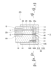
- FIG. 1 is a longitudinal sectional view of a nebulizer according to a first embodiment
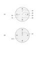
- FIG. FIG. (A) is an end view taken along line IIa-IIa in FIG.
- FIG. (B) is an end view taken along line IIb-IIb in FIG.
- FIG. (C) is an end view taken along line IIc-IIc in FIG.
- FIG. 4 is an end view taken along line IV-IV in FIG. 3
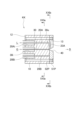
- FIG. 10 is a vertical cross-sectional view of a nebulizer according to a third embodiment
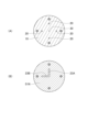
- FIG. (A) is an end view taken along line VIa-VIa in FIG. FIG.
- FIG. (B) is an end view taken along line VIb-VIb in FIG. It is a longitudinal cross-sectional view of a nebulizer according to a fourth embodiment.
- FIG. (A) is an end view taken along line VIIIa-VIIIa in FIG.
- FIG. (B) is an end view taken along line VIIIb-VIIIb in FIG.
- FIG. (C) is an end view taken along line VIIIc-VIIIc in FIG. It is a longitudinal section of a nebulizer concerning a 5th embodiment.
- FIG. 10 is an end view taken along line XX in FIG. 9;
- FIG. 10 is a vertical cross-sectional view of a nebulizer according to another embodiment;
- FIG. 11 is a vertical cross-sectional view of a nebulizer according to a sixth embodiment
- FIG. (A) is an end view taken along line XIIIa-XIIIa in FIG.
- FIG. (B) is an end view taken along line XIIIb--XIIIb in FIG.
- FIG. (C) is an end view taken along line XIIIc-XIIIc in FIG.
- FIG. 11 is a vertical cross-sectional view of a nebulizer according to a seventh embodiment
- FIG. (A) is an end view taken along line XVa-XVa in FIG.
- FIG. (B) is an end view taken along line XVb-XVb in FIG.
- FIG. 11 is a vertical cross-sectional view of a nebulizer according to an eighth embodiment
- FIG. (A) is an end view taken along line XVIIa-XVIIa in FIG.
- FIG. (B) is an end view taken along line XVIIb-XVIIb in FIG.
- FIG. 20 is a vertical cross-sectional view of a nebulizer according to a ninth embodiment
- FIG. (A) is an end view taken along line XIXa-XIXa in FIG.
- FIG. (B) is an end view taken along line XIXb-XIXb in FIG.
- FIG. 20 is a vertical cross-sectional view of a nebulizer according to a tenth embodiment
- FIG. 20 is a vertical cross-sectional view of a nebulizer according to an eleventh embodiment
- a nebulizer according to a first embodiment of the present invention is used to atomize a liquid sample to obtain sample droplets.
- a sample droplet is introduced into an excitation/ionization source or the like of an analysis device and subjected to analysis.
- the excitation/ionization source or the like is, for example, a plasma in an ICP analyzer, generated by a plasma torch.
- a sample droplet is introduced into a light scattering detector. Such detectors are also included in excitation/ionization sources and the like.
- the nebulizer AA of this embodiment has a base portion 10 and a tip portion 50 .
- the base portion 10 is a rod-shaped member having a circular cross section.
- One end face of the base portion 10 is called a rear face 12 and the other end face is called a front face 13 .
- the posterior surface 12 and the anterior surface 13 are planes perpendicular to the central axis of the base 10 .
- Two channels are formed in the base 10 along the axial direction: a base liquid channel 20 and a base gas channel 30 .
- the base liquid channel 20 has a liquid inlet 20i opening to the rear surface 12 and a liquid outlet 20o opening to the front surface 13.
- a base liquid channel 20 communicates between a liquid inlet 20i and a liquid outlet 20o.
- the base gas channel 30 has a gas inlet 30i opening at the rear surface 12 and a gas outlet 30o opening at the front surface 13.
- a base gas channel 30 communicates between a gas inlet 30i and a gas outlet 30o.
- the base liquid channel 20 and the base gas channel 30 are arranged in parallel at adjacent positions.
- the base portion gas flow path 30 is arranged along the central axis of the base portion 10 .
- the base portion liquid channel 20 is arranged at a position eccentric from the central axis of the base portion 10 .
- the inner diameters of the base liquid channel 20 and the base gas channel 30 can be set arbitrarily. For example, if the inner diameter of the base liquid channel 20 is set to 0.3 mm to 1.0 mm, clogging with suspended solids and the like can be suppressed.
- the base gas channel 30 may be narrower than the base liquid channel 20 .
- the inner diameter of the base gas channel 30 is, for example, 0.1 mm to 1.0 mm.
- the inner diameters of the base liquid channel 20 and the base gas channel 30 may be the same. In this case, the usage of the two channels can be interchanged. That is, the central channel may be used as the base liquid channel and the eccentric channel may be used as the base gas channel.
- the tip portion 50 is joined to the front surface 13 of the base portion 10 .
- the tip 50 consists of one or more channel forming plates.
- the tip portion 50 consists of a first mold channel forming plate 51A and a second mold channel forming plate 51B. Both the first mold channel forming plate 51A and the second mold channel forming plate 51B are disk-shaped members.
- the first mold channel forming plate 51A and the second mold channel forming plate 51B are joined to the front surface 13 of the base portion 10 in this order. That is, the first mold flow path forming plate 51A is provided so that the rear surface 52A contacts the front surface 13 of the base portion 10. As shown in FIG.
- the second mold channel forming plate 51B is provided so that the rear surface 52B contacts the front surface 53A of the first mold channel forming plate 51A.
- the second type channel forming plate 51B is arranged at the forefront of the nebulizer AA.
- the tip portion 50 is formed with a tip portion liquid flow channel, a tip portion gas flow channel, and ejection holes.
- the ejection hole is a hole for ejecting a mixed fluid of gas and liquid sample droplets.
- the tip liquid channel is a channel that guides the liquid sample discharged from the liquid outlet 20o to the ejection hole.
- the tip portion gas channel is a channel that guides the gas discharged from the gas outlet 30o to the ejection hole.
- the first type flow path forming plate 51A has a first through hole 21 and a second through hole 31.
- Both the first through-hole 21 and the second through-hole 31 are holes that communicate between the rear surface 52A and the front surface 53A of the first mold flow path forming plate 51A.
- the first through hole 21 is formed at a position corresponding to the liquid outlet 20o.
- the second through hole 31 is formed at a position corresponding to the gas outlet 30o.
- a groove 23 extending from the opening of the first through-hole 21 to the opening of the second through-hole 31 is formed in the front surface 53A of the first mold flow path forming plate 51A. ing.
- the inner diameter of the first through hole 21 may be the same as the inner diameter of the base portion liquid channel 20 .
- the inner diameter of the second through hole 31 may be the same as the inner diameter of the base gas channel 30, but is preferably smaller.
- the inner diameter of the second through hole 31 is preferably 5 to 50 ⁇ m. By doing so, the shear force of the gas is increased, and finer droplets can be generated.
- the inner diameter of the second through hole 31 may be the same throughout, but may have a taper that narrows from the inlet toward the outlet.
- the second through-hole 31 preferably has an inner diameter of the inlet equal to the inner diameter of the gas outlet 30o and has a taper with an outlet inner diameter of 5 to 50 ⁇ m. By doing so, it is possible to increase the shearing force of the gas while reducing the pressure loss at the connecting portion between the base portion gas flow path 30 and the second through hole 31 .
- the shape of the groove 23 is not particularly limited, and various shapes such as a V shape, a flat bottom shape, and a round bottom shape can be adopted. Moreover, the depth of the groove 23 can be set arbitrarily. For example, if the depth of the groove 23 is as shallow as 0.02 mm to 0.5 mm, the liquid sample can be made into a thin liquid film, and the spray efficiency can be improved.
- ejection holes 40 are formed in the second mold flow path forming plate 51B at positions corresponding to the gas outlets 30o.
- the ejection hole 40 is a cone-shaped through hole having a small diameter opening on the rear surface 52B and a large diameter opening on the front surface 53B.
- the cross-sectional shape of the ejection hole 40 particularly the shape of the opening of the rear surface 52B, is generally circular, but is not limited to this.
- the cross-sectional shape of the ejection hole 40 may be rectangular.
- the base portion liquid channel 20 and the first through hole 21 are connected, and the base portion gas channel 30 and the second through hole 31 are connected. connects.
- the second mold channel forming plate 51B is joined to the front surface 53A of the first mold channel forming plate 51A, the grooves 23 are combined with the rear surface 52B of the second mold channel forming plate 51B to form channels.
- the first through hole 21 and groove 23 form the tip liquid flow path, and the second through hole 31 forms the tip gas flow path.
- a flexible tube for flowing a liquid sample or gas can be inserted into the liquid inlet 20i and the gas inlet 30i, respectively.
- a liquid sample L introduced from the liquid inlet 20i is guided to the ejection hole 40 through the base liquid channel 20 and the tip liquid channel (the first through hole 21 and the groove 23).
- a gas G introduced from the gas inlet 30i is guided to the ejection hole 40 through the base gas channel 30 and the tip gas channel (second through hole 31).
- the liquid sample L reaching the ejection hole 40 becomes fine droplets D due to the shearing force of the gas G, and is ejected from the ejection hole 40 .
- the nebulizer AA has a fixing part that fixes the tip part 50 to the base part 10 .
- the fixing portion of this embodiment is a cylindrical member 61 into which the base portion 10 is inserted.
- the front edge of the cylindrical member 61 is joined to the outer peripheral edge of the second mold flow path forming plate 51B.
- the tubular member 61 and the second mold flow path forming plate 51B constitute one component.
- a female thread is formed on the inner peripheral surface of the rear end portion of the tubular member 61 .
- a male thread is formed on the outer peripheral surface of the base portion 10 .
- the distal end portion 50 is fixed to the base portion 10 by screwing the cylindrical member 61 and the base portion 10 together.
- the state in which the first mold channel forming plate 51A and the second mold channel forming plate 51B are stacked can be maintained.
- the fixed part is not limited to the cylindrical member 61 as long as it can fix the tip part 50 to the base part 10 .
- Other examples of securing portions are described in the description of other embodiments. Note that the base portion 10, the tip portion 50, and the flow path forming plates may be integrated by heat sealing, adhesive, or the like after being combined.
- the front surface 13 of the base 10 and the rear surface 52A of the first mold channel forming plate 51A, and the front surface 53A of the first mold channel forming plate 51A, to prevent the liquid sample from leaking out of the liquid channel. and the rear surface 52B of the second mold flow path forming plate 51B are preferably liquid-tightly adhered. Therefore, these surfaces are preferably polished smooth surfaces.
- a flexible sheet may be sandwiched between these members. For this sheet, for example, a silicone sheet, a rubber sheet, or the like can be used. A hole is formed in the sheet so as not to block the flow path.
- the first through hole 21 of the first mold flow path forming plate 51A is formed at an eccentric position.
- the nebulizer AA has a detent for the first mold flow path forming plate 51A.
- a detent in this embodiment is a pin 71 inserted into a hole formed in the base portion 10 and the first mold flow path forming plate 51A.
- the pin 71 is inserted in three places around the central axis, but the present invention is not limited to this.
- the detent is not limited to the pin 71 as long as it can fix the angle around the central axis of the flow path forming plate at a suitable angle. Other examples of detents are described in the description of other embodiments.
- the materials of the various parts that make up the nebulizer AA preferably have chemical stability that is resistant to attack by acids, organic solvents, etc., and also have mechanical strength that allows fine processing.
- Examples include resin, glass, ceramics, carbon, and metal.
- resins include PEEK (polyetheretherketone), PPS (polyphenylene sulfide), PFA (perfluoroalkoxyalkane), PTFE (polytetrafluoroethylene), and polyimide.
- resins include PEEK (polyetheretherketone), PPS (polyphenylene sulfide), PFA (perfluoroalkoxyalkane), PTFE (polytetrafluoroethylene), and polyimide.
- metals include acid-resistant metals such as gold, platinum, and iridium. Alternatively, metal coated with resin, glass, ceramics, carbon, or the like may be used.
- the tip portion liquid flow path (first through hole 21 and groove 23) of the nebulizer AA is a restricted space flow path surrounded by walls. Unlike the Babington type nebulizer, the liquid sample is not flowed down by gravity, so the attitude of the nebulizer AA is not restricted. In addition, since the liquid sample can be sucked up by the flow of gas, the liquid sample can be atomized without a liquid-sending pump. Of course, you may use a liquid-sending pump.
- the tip liquid channel is a restricted space channel, there is a risk of clogging with suspended solids. If the liquid channel at the tip portion is clogged with suspended matter or the like, the suspended matter or the like can be easily removed by removing and washing the channel forming plates 51A and 51B. Also, even if some parts are damaged, the function can be restored by replacing the parts.
- the nebulizer AA has a tip liquid channel, a tip gas channel and ejection holes formed by combining channel forming plates 51A and 51B.
- the flow path forming plates 51A and 51B have a simple structure in which through holes and grooves are formed in a plate material. Therefore, the flow path forming plates 51A and 51B with high dimensional accuracy can be easily manufactured.
- the relative positional relationship between the outlet of the liquid channel and the outlet of the gas channel determines the atomization performance of the nebulizer.
- a coaxial nebulizer requires adjustment of the positional relationship between an inner tube and an outer tube, each having a length of several tens of millimeters, which makes highly accurate adjustment difficult.
- the flow path forming plates 51A and 51B with high dimensional accuracy are combined to form the tip portion liquid flow path and the tip portion gas flow path. is easy.
- the first type flow path forming plate 51A As the first type flow path forming plate 51A, a plurality of types of flow path forming plates having different inner diameters of the first through holes 21 and the second through holes 31 and different depths and widths of the grooves 23 may be prepared. Then, by exchanging the first-type channel forming plate 51A, liquid samples with various characteristics and flow rates can be handled.
- the configurations of the tip part liquid flow path and the tip part gas flow path can be changed. That is, by combining the flow path forming plates, it is possible to construct the tip portion liquid flow path and the tip portion gas flow path having desired configurations. This results in a nebulizer with nebulization performance suitable for liquid samples with various characteristics and flow rates.
- the distal end portion 50 may be constructed by combining a plurality of flow path forming plates, or may be constructed by one flow path forming plate. Other examples of combinations of flow path forming plates will be described below.
- the nebulizer BB of this embodiment has a base portion 10 and a tip portion 50 .
- the base portion 10 has a shape similar to that of the first embodiment.
- the tip portion 50 is composed of a third type flow path forming plate 51C and a second type flow path forming plate 51B.
- the third mold channel forming plate 51C and the second mold channel forming plate 51B are joined to the front surface 13 of the base portion 10 in this order.
- the second mold flow path forming plate 51B has the same shape as that of the first embodiment. Note that the second mold flow path forming plate 51B may be omitted.
- grooves 23 extending from positions corresponding to the liquid outlets 20o to positions corresponding to the gas outlets 30o are formed in the rear surface 52C of the third mold flow path forming plate 51C. Further, ejection holes 40a are formed at positions corresponding to the gas outlets 30o in the third die flow path forming plate 51C.
- the depth of the groove 23 may be constant, or the portion near the ejection hole 40a may be shallow. By deepening the portion of the groove 23 that is far from the ejection hole 40a, clogging with suspended solids can be suppressed. At the same time, if the portion of the groove 23 near the ejection hole 40a is made shallow, the liquid sample can be made into a thin liquid film, and the spray efficiency can be improved.
- the groove 23 is combined with the front surface 13 of the base portion 10 to form a tip portion liquid channel connecting the liquid outlet 20o and the gas outlet 30o. do.
- the ejection holes 40a of the third mold channel forming plate 51C and the ejection holes 40b of the second mold channel forming plate 51B are aligned. They are connected to form one ejection port.
- the liquid sample L introduced from the liquid inlet 20i is guided to the ejection hole 40a through the base liquid channel 20 and the tip liquid channel (groove 23).
- a gas G introduced from the gas inlet 30i passes through the base gas passage 30 and is led to the ejection holes 40a.
- the liquid sample L reaching the ejection hole 40a becomes fine droplets D due to the shearing force of the gas G, and is ejected from the ejection hole 40a.
- a portion of the groove 23 corresponding to the gas outlet 30o can be said to be a tip portion gas flow path.
- a cylindrical member 61 is coupled to the outer peripheral edge of the second mold flow path forming plate 51B.
- the distal end portion 50 is fixed to the base portion 10 by screwing the cylindrical member 61 and the base portion 10 together.
- the nebulizer BB has a detent for the third type flow path forming plate 51C.
- the detent of this embodiment consists of a concave portion 72 formed on the front surface 13 of the base portion 10 and a convex portion 73 formed on the rear surface 52C of the third die flow path forming plate 51C. By fitting the convex portion 73 into the concave portion 72, the angle around the central axis of the third mold flow path forming plate 51C can be fixed.
- the posture of the nebulizer BB is not limited.
- the liquid sample can be sucked up by the flow of gas, the liquid sample can be atomized without a liquid-sending pump.
- the tip portion liquid flow path is a restricted space flow path, there is a risk of clogging with suspended solids or the like.
- the suspended matter or the like can be easily removed by removing and washing the channel forming plates 51C and 51B.
- the nebulizer CC of this embodiment has a base portion 10 and a tip portion 50 .
- the base portion 10 has a shape similar to that of the first embodiment.
- the tip portion 50 consists of a fourth type flow path forming plate 51D and a second type flow path forming plate 51B.
- the fourth mold channel forming plate 51D and the second mold channel forming plate 51B are joined to the front surface 13 of the base portion 10 in this order.
- the second mold flow path forming plate 51B has the same shape as that of the first embodiment.
- the rear surface 52D of the fourth mold flow path forming plate 51D has a groove 23 extending from a position corresponding to the liquid outlet 20o to a position near the position corresponding to the gas outlet 30o. formed.
- the fourth die flow path forming plate 51D has a first through hole 21 formed at the end of the groove 23 (position near the above), and a second through hole 31 formed at a position corresponding to the gas outlet 30o. ing.
- the second through hole 31 extends along the central axis.
- the first through hole 21 is inclined with respect to the central axis, and the opening of the first through hole 21 on the front surface 53 ⁇ /b>D side approaches the second through hole 31 . Therefore, as shown in FIG.
- the opening of the first through-hole 21 and the opening of the second through-hole 31 are adjacent to each other on the front surface 53D.
- the ejection hole 40 of the second mold flow path forming plate 51B has an opening on the rear surface 52B side, and an opening of the first through hole 21 and an opening of the second through hole 31 on the front surface 53D side of the fourth mold flow path forming plate 51D. It has a size that includes the part.
- the groove 23 is combined with the front surface 13 of the base portion 10 to form a channel connected to the base portion liquid channel 20. Also, the base gas flow path 30 and the second through hole 31 are connected. The groove 23 and the first through hole 21 form the tip liquid channel, and the second through hole 31 form the tip gas channel.
- a liquid sample L introduced from the liquid inlet 20i is guided to the ejection hole 40 through the base liquid channel 20 and the tip liquid channel (the groove 23 and the first through hole 21).
- a gas G introduced from the gas inlet 30i is guided to the ejection hole 40 through the base portion gas channel 30 and the tip portion liquid channel (second through hole 31).
- the liquid sample L reaching the ejection hole 40 is sheared by the flow of the adjacent gas G, becomes fine droplets D, and is ejected from the ejection hole 40 .
- the nebulizer DD of this embodiment has a base portion 10 and a tip portion 50 .
- the base portion 10 has a shape similar to that of the first embodiment.
- the tip portion 50 is composed of a fifth type flow path forming plate 51E and a second type flow path forming plate 51B.
- the fifth mold channel forming plate 51E and the second mold channel forming plate 51B are bonded to the front surface 13 of the base portion 10 in this order.
- the second mold flow path forming plate 51B has the same shape as that of the first embodiment.
- the rear surface 52E of the fifth mold flow path forming plate 51E has a groove 23 extending from a position corresponding to the liquid outlet 20o to a position near the position corresponding to the gas outlet 30o. formed.
- the fifth mold flow path forming plate 51E is formed with the first through hole 21 at the end of the groove 23 (position near the above), corresponding to the gas outlet 30o.
- a second through hole 31 is formed at the position.
- a concave portion 24 is formed in a circular area around the opening of the second through-hole 31 on the front surface 53E of the fifth mold flow path forming plate 51E.
- the diameter of the recess 24 is larger than the inner diameter of the second through hole 31 .
- the recess 24 is also connected to the opening of the first through hole 21 .
- the groove 23 is combined with the front surface 13 of the base portion 10 to form a channel connected to the base portion liquid channel 20. Also, the base gas flow path 30 and the second through hole 31 are connected.
- the second mold flow path forming plate 51B is joined to the front surface 53E of the fifth mold flow path forming plate 51E, the peripheral edge portion of the recess 24 becomes the rear surface 52B of the second mold flow path forming plate 51B (annular area around the ejection hole 40). ) to form a channel.
- the groove 23, the first through hole 21 and the recess 24 form the tip liquid flow path, and the second through hole 31 forms the tip gas flow path.
- a liquid sample L introduced from the liquid inlet 20i is guided to the ejection hole 40 through the base liquid channel 20 and the tip liquid channel (the groove 23, the first through hole 21 and the recess 24).
- a gas G introduced from the gas inlet 30i is guided to the ejection hole 40 through the base gas channel 30 and the tip gas channel (second through hole 31).
- the liquid sample L spreads over the circular concave portion 24 and forms a liquid film.
- the liquid sample L can be atomized by passing the liquid film over the gas outlet (the opening of the second through-hole 31).
- the nebulizer EE of this embodiment has a base portion 10 and a tip portion 50 .
- the base portion 10 has a shape similar to that of the first embodiment.
- the central channel is used as the base liquid channel 20 and the eccentric channel is used as the base gas channel 30 .
- the tip portion 50 has a sixth type flow path forming plate 51F, a spacer plate 54 and a seventh type flow path forming plate 51G.
- the sixth mold channel forming plate 51F, the spacer plate 54 and the seventh mold channel forming plate 51G are joined to the front surface 13 of the base portion 10 in this order. That is, the spacer plate 54 is sandwiched between the sixth mold channel forming plate 51F and the seventh mold channel forming plate 51G.
- a first through hole 21 is formed at a position corresponding to the liquid outlet 20o, and a second through hole 31 is formed at a position corresponding to the gas outlet 30o in the sixth mold flow path forming plate 51F.
- the sixth mold flow path forming plate 51F has a cone-shaped nozzle 36 projecting from the front surface 53F.
- the nozzle 36 is arranged at a position corresponding to the liquid outlet 20o. Further, as shown in FIG. 10, the first through hole 21 penetrates through the center of the nozzle 36 .
- the spacer plate 54 is an annular member.
- the central opening of the spacer plate 54 is sized to accommodate the nozzles 36 and the second through holes 31 of the sixth flow path forming plate 51F.
- a spacer plate 54 is provided on the outer edge of the front surface 53F of the sixth mold flow path forming plate 51F.
- the material of the spacer plate 54 is not particularly limited, it is preferable that the shape can be kept constant for a long period of time.
- a flexible plate such as a silicone plate or a rubber plate may be used as the spacer plate 54 .
- a flexible plate can be used to prevent the gas from leaking out of the channel.
- the sixth mold flow path forming plate 51F and the spacer plate 54 may be integrated into one component.
- a through-hole is formed in the seventh mold channel forming plate 51G at a position corresponding to the liquid outlet 20o.
- This through hole is composed of a conical nozzle accommodation hole 38 on the rear surface 52G side and a jet hole 40 on the front surface 53G side.
- the sixth mold channel forming plate 51F When the sixth mold channel forming plate 51F is joined to the front surface 13 of the base portion 10, the base portion liquid channel 20 and the first through hole 21 are connected, and the base portion gas channel 30 and the second through hole 31 are connected. connects. Further, when the seventh mold channel forming plate 51G is joined to the sixth mold channel forming plate 51F with the spacer plate 54 interposed therebetween, the front surface 53F of the sixth mold channel forming plate 51F and the seventh mold channel forming plate 51G are separated. An annular flow path is formed between the rear surface 52G. Further, the nozzle 36 is accommodated in the nozzle accommodation hole 38 to form a cylindrical flow path.
- the first through hole 21 forms the tip liquid flow path, the second through hole 31, the annular flow path between the front surface 53F and the rear surface 52G, and the cylindrical flow path between the nozzle 36 and the nozzle receiving hole 38.
- a channel forms a tip gas channel. That is, by housing the nozzle 36 in the nozzle housing hole 38, a coaxial flow path can be formed in which a liquid flow path is arranged in the center and a cylindrical gas flow path is arranged around it.
- a liquid sample L introduced from the liquid inlet 20i is guided to the ejection hole 40 through the base liquid channel 20 and the tip liquid channel (first through hole 21).
- the gas G introduced from the gas inlet 30i is guided to the ejection hole 40 through the base gas flow channel 30 and the tip gas flow channel (the second through hole 31, the annular flow channel 53F, and the cylindrical flow channel 36). .
- the liquid sample L reaching the ejection hole 40 becomes fine droplets D due to the shearing force of the gas G, and is ejected from the ejection hole 40 . Since a coaxial channel is formed by combining the nozzle 36 and the nozzle housing hole 38, the nebulizer EE of this embodiment has the same function as a coaxial nebulizer.
- the nebulizer EE forms a coaxial channel with a cone-shaped nozzle 36 and does not use a long and narrow capillary tube. Therefore, problems such as the inner tube being easily damaged and the tip of the inner tube vibrating due to the high-speed gas flow, which are seen in coaxial nebulizers, do not occur. In addition, when the liquid flow path of the tip portion is clogged with suspended matter, the suspended matter can be easily removed by removing the flow path forming plates 51F and 51G and cleaning.
- the nebulization efficiency of a coaxial nebulizer largely depends on the gap between the inner tube and the outer tube and the relative relationship between the tip positions of the inner tube and the outer tube.
- the nebulizer EE of the present embodiment can change the thickness or the number of spacer plates 54 to change the relative relationship between the gap between the nozzle 36 and the nozzle housing hole 38 and the tip position between the nozzle 36 and the nozzle housing hole 38. can be adjusted.
- the flow path forming plates 51F, 51G and spacer plate 54 have a simple structure, they can be manufactured with high dimensional accuracy. By combining the flow path forming plates 51F and 51G with high dimensional accuracy and the spacer plate 54, the gap between the nozzle 36 and the nozzle housing hole 38 and the relative relationship between the tip positions of the nozzle 36 and the nozzle housing hole 38 can be adjusted with high precision. can.
- the nozzle 36 may be formed with a capillary.
- a capillary may be inserted into a hole formed in the center of the sixth mold channel forming plate 51F and fixed.
- a fixing method fitting, heat sealing, adhesion, or the like can be considered.
- a flange may be provided at the rear end of the capillary to be fitted into a recess formed in the rear surface 52F of the sixth mold flow path forming plate 51F.
- Glass tubes, PFA tubes, etc. can be used as capillaries.
- the capillary can be much shorter than the capillary used as the inner tube of a conventional coaxial nebulizer.
- the capillary length is 2-5 mm.
- Capillaries can be manufactured with high precision using microfabrication techniques such as injection molding, machining, and MEMS.
- the dimensional accuracy of the nozzle 36 can be increased by using a capillary with high dimensional accuracy. Therefore, the relative relationship between the gap between the nozzle 36 and the nozzle housing hole 38 and the tip position between the nozzle 36 and the nozzle housing hole 38 can be adjusted with high accuracy.
- the manufacturing cost can be reduced compared to the case where the nozzles 36 are formed by processing a plate.
- the nebulizer FF of this embodiment has a base portion 10 and a tip portion 50 .
- a channel arranged along the central axis of the base portion 10 is the base portion gas channel 30 .
- the two channels arranged at two positions eccentric from the central axis of the base 10 are the first base liquid channel 20A and the second base liquid channel 20B.
- the opening on the rear surface 12 side of the first base liquid channel 20A is defined as a first liquid inlet 20Ai, and the opening on the front surface 13 side is defined as a first liquid outlet 20Ao.
- the opening on the rear surface 12 side of the second base liquid channel 20B is a second liquid inlet 20Bi, and the opening on the front surface 13 side is a second liquid outlet 20Bo.
- the tip portion 50 consists of an eighth type flow path forming plate 51H and a ninth type flow path forming plate 51J.
- the eighth mold channel forming plate 51H and the ninth mold channel forming plate 51J are bonded to the front surface 13 of the base portion 10 in this order.
- the eighth mold channel forming plate 51H has a first through hole 21 formed at a position corresponding to the first liquid outlet 20Ao, and a second liquid outlet 20Bo.
- a second through hole 22 is formed at a corresponding position.
- a first concave portion 34 is formed in a circular area centered on a position corresponding to the gas outlet 30o on the rear surface 52H of the eighth mold flow path forming plate 51H.
- a third through hole 31 is formed adjacent to the first through hole 21, and a fourth through hole 32 is formed adjacent to the second through hole 22. there is The third through hole 31 and the fourth through hole 32 communicate with the first recess 34 respectively.
- FIG. 13B a third through hole 31 is formed adjacent to the first through hole 21, and a fourth through hole 32 is formed adjacent to the second through hole 22.
- a second concave portion 24 is formed in a circular area around the opening of the third through hole 31 on the front surface 53H of the eighth die flow path forming plate 51H.
- the diameter of the second recess 24 is larger than the inner diameter of the third through hole 31 .
- the second recess 24 is also connected to the opening of the first through hole 21 .
- a third concave portion 25 is formed in a circular area around the opening of the fourth through hole 32 on the front surface 53H.
- the diameter of the third recess 25 is larger than the inner diameter of the fourth through hole 32 .
- the third recess 25 is also connected to the opening of the second through hole 22 .
- the first ejection holes 41 are formed at positions corresponding to the third through holes 31 in the ninth mold flow path forming plate 51J.
- a second ejection hole 42 is formed at a position corresponding to the fourth through hole 32 . Both the first ejection hole 41 and the second ejection hole 42 are cone-shaped through holes.
- the eighth type channel forming plate 51H When the eighth type channel forming plate 51H is joined to the front surface 13 of the base portion 10, the first base portion liquid channel 20A and the first through hole 21 are connected, and the second base portion liquid channel 20B and the second base portion liquid channel 20B are connected to each other.
- the through hole 22 is connected.
- the first concave portion 34 and the front surface 13 of the base portion 10 are combined to form a branch flow channel connected to the base portion gas flow channel 30 .
- the ninth-type flow passage forming plate 51J When the ninth-type flow passage forming plate 51J is joined to the front surface 53H of the eighth-type flow passage forming plate 51H, the peripheral edge portion of the second recess 24 becomes the rear surface 52J of the ninth-type flow passage forming plate 51J (the first jet hole 41). surrounding annular region) to form a flow channel.
- the peripheral edge of the third recess 25 is covered with the rear surface 52J (annular area around the second ejection hole 42) of the ninth mold flow path forming plate 51J to form a flow path.
- the first concave portion 34, the third through-hole 31 and the fourth through-hole 32 form a tip portion gas flow path branched into two on the way.
- the first through hole 21 and the second recess 24 form the first tip liquid flow path, and the second through hole 22 and the third recess 25 form the second tip liquid flow path.
- the first liquid sample L1 introduced from the first liquid inlet 20Ai passes through the first base liquid channel 20A and the first tip liquid channel (the first through-hole 21 and the second recess 24), and the first ejection It is guided to hole 41 .
- a gas G introduced from the gas inlet 30i is guided to the first ejection hole 41 through the base gas flow path 30 and the tip gas flow path (the first recess 34 and the third through hole 31).
- the first liquid sample L1 spreads into the circular second concave portion 24 and becomes a liquid film.
- the first liquid sample L1 can be atomized by passing the liquid film over the gas outlet (the opening of the third through-hole 31).
- the second liquid sample L2 introduced from the second liquid inlet 20Bi passes through the second base liquid channel 20B and the second tip liquid channel (the second through-hole 22 and the third recess 25), and is ejected through the second jet. It is led to hole 42 .
- the gas G introduced from the gas inlet 30i is led to the second ejection hole 42 through the base gas flow channel 30 and the tip gas flow channel (the first recess 34 and the fourth through hole 32).
- the second liquid sample L2 spreads over the circular third recess 25 and forms a liquid film.
- the second liquid sample L2 can be atomized by passing this liquid film over the gas outlet (the opening of the fourth through-hole 32).
- the nebulizer FF can simultaneously spray two types of liquid samples from separate ejection holes 41 and 42 . Therefore, two types of liquid samples can be sprayed without being mixed. For example, even an incompatible combination such as an aqueous solution sample and an organic solvent sample can be stably sprayed. In addition, even a combination of liquids that, when mixed, causes reactions such as neutralization reaction, oxidation-reduction reaction, and solation reaction to generate precipitates and air bubbles, or that greatly changes viscosity, can be sprayed stably. Even if droplets that have once become fine droplets collide with each other, it is difficult for them to grow into large droplets.
- the nebulizer GG of this embodiment has a base portion 10 and a tip portion 50 .
- the central channel is used as the base liquid channel 20 and the two eccentric channels are used as the first base gas channel 30A and the second base gas channel 30B, respectively.
- the opening on the rear surface 12 side of the first base gas flow path 30A is a first gas inlet 30Ai, and the opening on the front surface 13 side is a first gas outlet 30Ao.
- the opening on the rear surface 12 side of the second base gas flow path 30B is a second gas inlet 30Bi, and the opening on the front surface 13 side is a second gas outlet 30Bo.
- the tip portion 50 is composed of a tenth mold channel forming plate 51K, a first spacer plate 55, an eleventh mold channel forming plate 51L, a second spacer plate 56 and a twelfth mold channel forming plate 51M.
- the tenth mold channel forming plate 51K, the first spacer plate 55, the eleventh mold channel forming plate 51L, the second spacer plate 56 and the twelfth mold channel forming plate 51M are bonded to the front surface 13 of the base portion 10 in this order. It is
- a first through hole 21 is formed at a position corresponding to the liquid outlet 20o in the tenth mold flow path forming plate 51K.
- a second through hole 31 is formed at a position corresponding to the first gas outlet 30Ao, and a third through hole 32a is formed at a position corresponding to the second gas outlet 30Bo.
- the tenth type flow path forming plate 51K has a cone-shaped first nozzle 36 projecting from the front surface 53K.
- the first nozzle 36 is arranged at a position corresponding to the liquid outlet 20o. As shown in FIG. 15A, the first through hole 21 penetrates the center of the first nozzle 36 .
- the first spacer plate 55 is an annular member.
- the central opening of the first spacer plate 55 is sized to accommodate the first nozzles 36 and the second through holes 31 of the tenth mold channel forming plate 51K.
- a through hole is formed in the first spacer plate 55 at a position corresponding to the third through hole 32a.
- a first spacer plate 55 is provided on the outer edge of the front face 53K of the tenth mold channel forming plate 51K. It should be noted that the tenth mold flow path forming plate 51K and the first spacer plate 55 may be integrated into one component.
- the eleventh type flow path forming plate 51L has a cylindrical second nozzle 37 protruding from the front surface 53L.
- the second nozzle 37 is arranged at a position corresponding to the liquid outlet 20o.
- a through hole penetrating through the center of the second nozzle 37 is formed in the eleventh mold flow path forming plate 51L.
- This through hole is composed of a cone-shaped first nozzle accommodation hole 38 on the rear surface 52L side and a jet hole 40 on the front surface 53L side.
- the eleventh mold flow path forming plate 51L is formed with a fourth through hole 32b at a position corresponding to the second gas outlet 30Bo.
- the second spacer plate 56 is an annular member.
- the central opening of the second spacer plate 56 has a size that encompasses the second nozzles 37 and the fourth through holes 32b of the eleventh mold flow path forming plate 51L.
- a second spacer plate 56 is provided on the outer edge of the front surface 53L of the eleventh mold flow path forming plate 51L. Note that the eleventh mold flow path forming plate 51L and the second spacer plate 56 may be integrated into one component.
- a through hole is formed in the twelfth type flow path forming plate 51M at a position corresponding to the liquid outlet 20o.
- This through hole is a second nozzle accommodation hole 39 that accommodates the second nozzle 37 .
- the base portion liquid channel 20 and the first through hole 21 are connected. Further, the first base gas flow channel 30A and the second through hole 31 are connected, and the second base gas flow channel 30B and the third through hole 32a are connected.
- the eleventh mold channel forming plate 51L is joined to the tenth mold channel forming plate 51K with the first spacer plate 55 interposed therebetween, the front surface 53K of the tenth mold channel forming plate 51K and the eleventh mold channel forming plate 51L are separated. An annular flow path is formed between the rear surface 52L. As shown in FIG. 15B, the first nozzle 36 is accommodated in the first nozzle accommodation hole 38 to form a cylindrical flow path. Moreover, the 3rd through-hole 32a and the 4th through-hole 32b are connected.
- the first through hole 21 forms the tip portion liquid flow path.
- the second through hole 31, the annular flow path between the front surface 53K and the rear surface 52L, and the cylindrical flow path between the first nozzle 36 and the first nozzle housing hole 38 form the first tip gas flow path.
- the third through hole 32a, the fourth through hole 32b, the annular flow path between the front surface 53L and the rear surface 52M, and the cylindrical flow path between the second nozzle 37 and the second nozzle housing hole 39 are A second tip gas flow path is formed.
- a liquid sample L introduced from the liquid inlet 20i is guided to the ejection hole 40 through the base liquid channel 20 and the tip liquid channel (first through hole 21).
- the first gas G1 introduced from the first gas inlet 30Ai passes through the first base gas channel 30A and the first tip gas channel (the second through hole 31, the annular channel 53K and the cylindrical channel 36). It is led through to the jet hole 40 .
- the liquid sample L reaching the ejection hole 40 becomes fine droplets D due to the shearing force of the first gas G1 and is ejected from the ejection hole 40 .
- the second gas G2 introduced from the second gas inlet 30Bi passes through the second base portion gas flow path 30B and the second tip portion gas flow path (the third through hole 32a, the fourth through hole 32b, the annular flow path 53L and the cylinder). It is led around the orifice 40 through the shape channel 37). Therefore, the second gas G2 forms a flow surrounding the liquid droplets D ejected from the ejection holes 40 .
- the sample droplets D By flowing the second gas G2 around the sample droplets D ejected from the ejection hole 40, the sample droplets D can be made finer and the spray direction can be controlled.
- Different types and target gases can be used as the first gas G1 and the second gas G2.
- a carrier gas can be used as the first gas G1
- a sheath gas can be used as the second gas G2.
- the sample droplet D can be cooled or heated.
- the nebulizer GG has a bolt 62 as a fixing portion that fixes the tip portion 50 to the base portion 10 .
- the bolt 62 has a male thread only at its tip. Through holes into which bolts 62 are inserted are formed in the base portion 10, the tenth mold channel forming plate 51K, the first spacer plate 55, the eleventh mold channel forming plate 51L and the second spacer plate .
- a female screw is formed in the twelfth die flow path forming plate 51M.
- a bolt 62 is inserted from the rear surface 12 of the base portion 10 and screwed to the twelfth mold channel forming plate 51M. Thereby, the tip portion 50 can be fixed to the base portion 10 .
- the bolt 62 also functions as a detent for the passage forming plate.
- the nebulizer HH of this embodiment has a base portion 10 and a tip portion.
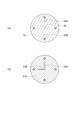
- a base portion gas flow path 30 is formed inside the base portion 10 along the central axis. Further, inside the base portion 10, a plurality of base portion liquid channels 20 are formed on the circumference around the base portion gas channel 30. As shown in FIG. The plurality of base liquid channels 20 are the same distance from the base gas channels 30 . Also, the plurality of base liquid channels 20 are arranged at equal angular intervals around the base gas channel 30 . In the example shown in FIG. 17A, four base liquid channels 20 are arranged at intervals of 90°.
- the tip portion consists of the third type flow path forming plate 51C.
- the third mold channel forming plate 51C is joined to the front surface 13 of the base portion 10 .
- a groove 23 extending radially from a position corresponding to the gas outlet 30o is formed in the rear surface 52C of the third mold flow path forming plate 51C. As shown in FIG. 17B, groove 23 has the same length as the distance between base liquid channel 20 and base gas channel 30 .
- the ejection holes 40 are formed at positions corresponding to the gas outlets 30o in the third die flow path forming plate 51C.
- the grooves 23 are combined with the front surface 13 of the base portion 10 to form the tip portion liquid flow channel.
- the tip liquid channel (groove 23 ) connects with one of the plurality of base liquid channels 20 .
- the rest of the base liquid channel 20 is closed by the rear surface 52C of the third mold channel forming plate 51C.
- a liquid sample L introduced from the selected liquid inlet 20i is guided to the ejection hole 40 through the base liquid channel 20 and the tip liquid channel (groove 23).
- a gas G introduced from the gas inlet 30i is guided to the ejection holes 40 through the base gas flow path 30 .
- the liquid sample L reaching the ejection hole 40 becomes fine droplets D due to the shearing force of the gas G, and is ejected from the ejection hole 40 .
- the nebulizer HH can selectively switch the channel through which the liquid sample L flows among the plurality of base liquid channels 20 .
- the nebulizer HH selects one of the plurality of base liquid channels 20 and connects it with the ejection port 40 . Therefore, if one base liquid channel 20 is clogged by suspended matter or damaged by chemicals, it can be switched to another base liquid channel 20 to continue using the nebulizer HH. In addition, by selectively using the plurality of base liquid channels 20 according to the type of liquid sample L (aqueous solution, organic solvent, etc.), the labor for cleaning the base liquid channels 20 can be saved.
- liquid sample L aqueous solution, organic solvent, etc.
- the nebulizer HH has a bolt 62 and a nut 63 as fixing parts for fixing the tip part to the base part 10 .
- Through-holes into which bolts 62 are inserted are formed in the base portion 10 and the third mold flow path forming plate 51C.
- a concave portion in which the nut 63 is fitted is formed in the front surface 53C of the third die flow path forming plate 51C.
- a bolt 62 is inserted from the rear surface 12 of the base 10 and tightened with a nut 63 . Thereby, the tip portion can be fixed to the base portion 10 .
- the nebulizer JJ according to the ninth embodiment has a base portion 10 and a tip portion.
- the base portion 10 has the same shape as that of the eighth embodiment.
- the tip portion is composed of the 13th type flow passage forming plate 51N.
- the thirteenth mold channel forming plate 51N is joined to the front surface 13 of the base portion 10 .
- the rear surface 52N of the thirteenth mold flow path forming plate 51N has two grooves radially extending from the position corresponding to the gas outlet 30o, that is, the first grooves 23A and the A second groove 23B is formed.
- Both the first groove 23A and the second groove 23B have the same length as the distance between the base liquid channel 20 and the base gas channel 30 .
- the angle between the first groove 23A and the second groove 23B is the same as the angular interval of the base liquid channel 20 (90° in the example shown in FIG. 19B).
- the thirteenth mold flow path forming plate 51N is formed with ejection holes 40 at positions corresponding to the gas outlets 30o.
- the first groove 23A is combined with the front surface 13 of the base portion 10 to form the first tip liquid channel.
- the first tip liquid channel (first groove 23A) connects with one of the plurality of base liquid channels 20 .
- a second groove 23B also mates with the front surface 13 of the base 10 to form a second tip liquid flow path.
- the second tip liquid channel (second groove 23B) connects to another one of the plurality of base liquid channels 20 .
- the rest of the base liquid channel 20 is closed by the rear surface 52N of the 13th type channel forming plate 51N.
- a first liquid sample L1 introduced from one selected liquid inlet 20i is guided to the ejection hole 40 through the base liquid channel 20 and the first tip liquid channel (first groove 23A). Further, the second liquid sample introduced from the other selected liquid inlet 20i is guided to the ejection hole 40 through the base portion liquid channel 20 and the second tip portion liquid channel (second groove 23B). be killed.
- the first liquid sample L1 and the second liquid sample are mixed immediately before the ejection hole 40 .
- a gas G introduced from the gas inlet 30i is guided to the ejection holes 40 through the base gas flow path 30 .
- the mixed liquid of the first liquid sample L1 and the second liquid sample becomes fine droplets D due to the shearing force of the gas G, and is ejected from the ejection hole 40 .
- the nebulizer HH can selectively switch between two flow paths for the liquid sample L among the plurality of base liquid flow paths 20 .
- the nebulizer JJ of this embodiment can mix and spray two types of liquid samples immediately before the ejection hole 40 . Therefore, it is possible to stably spray a combination of liquid samples that would be difficult to spray if mixed, or a combination of liquid samples that cannot be mixed.
- the nebulizer KK of this embodiment has a base portion 10 and a tip portion.
- a base portion gas flow path 30 is formed inside the base portion 10 along the central axis.
- a plurality of base portion liquid channels 20A and 20B having different inner diameters are formed on a circumference around the base portion gas channel 30.
- two base liquid channels 20A and 20B are arranged at intervals of 180°.
- the first base liquid channel 20A is a large diameter channel and the second base liquid channel 20B is a small diameter channel.
- the inner diameter of the first base liquid channel 20A is 300 ⁇ m and the inner diameter of the second base liquid channel 20B is 75 ⁇ m.
- the tip portion consists of the 14th type flow passage forming plate 51P.
- the fifteenth mold channel forming plate 51P is joined to the front surface 13 of the base portion 10 .
- a plurality of grooves 23A having different widths are radially formed from positions corresponding to the gas outlets 30o along the radial direction. 23B.
- a wide first groove 23A corresponding to the inner diameter of the first base liquid channel 20A and a narrow second groove corresponding to the inner diameter of the second base liquid channel 20B 23B are arranged.
- the width and depth of the first groove 23A are 300 ⁇ m, and the width and depth of the second groove 23B are 75 ⁇ m.
- the angle between the first groove 23A and the second groove 23B is 90°.
- the 14th type flow path forming plate 51P is formed with ejection holes 40 at positions corresponding to the gas outlets 30o.
- the 14th type channel forming plate 51P is joined to the base portion 10 so that the first base portion liquid channel 20A and the first groove 23A are connected.
- the first groove 23A then mates with the front surface 13 of the base 10 to form the first tip liquid flow path.
- the second base liquid channel 20B is closed by the rear surface 52P of the fourteenth type channel forming plate 51P.
- a liquid sample L introduced from the first liquid inlet 20Ai is guided to the ejection hole 40 through the first base liquid channel 20A and the first tip liquid channel (first groove 23A).
- a gas G introduced from the gas inlet 30i is guided to the ejection holes 40 through the base gas flow path 30 .
- the liquid sample L reaching the ejection hole 40 becomes fine droplets D due to the shearing force of the gas G, and is ejected from the ejection hole 40 .
- the 14th type channel forming plate 51P may be joined to the base portion 10 so that the second base portion liquid channel 20B and the second groove 23B are connected.
- the second groove 23B then mates with the front surface 13 of the base 10 to form a second tip liquid flow path.
- the first base liquid channel 20A is closed by the rear surface 52P of the fourteenth type channel forming plate 51P.
- the liquid sample L introduced from the second liquid inlet 20Bi is guided to the ejection hole 40 through the second base liquid channel 20B and the second tip liquid channel (second groove 23B).
- a gas G introduced from the gas inlet 30i is guided to the ejection holes 40 through the base gas flow path 30 .
- the liquid sample L reaching the ejection hole 40 becomes fine droplets D due to the shearing force of the gas G, and is ejected from the ejection hole 40 .
- the flow rate of the liquid sample supplied to the nebulizer is usually about 0.5 to 1.0 mL/min, and the inner diameter of the liquid channel is also suitable for this flow rate.
- Introduction of liquid samples at very low flow rates (e.g., 0.1 mL/min or less) into such nebulizers will dilute the sample or reduce resolution when analyzing eluates from liquid chromatographic devices. analysis becomes difficult.
- the nebulizer KK of this embodiment can selectively switch the inner diameter of the liquid channel.
- the width of the liquid channel can be selected according to liquid samples with various flow rates. Therefore, one nebulizer KK can handle a wide range of flow rates.
- the nebulizer LL of this embodiment has a tubular body 80 .
- the base portion 10 and the tip portion 50 are attached to the tip of the cylindrical body 80 .
- the base portion 10 and the tip portion 50 of the fifth embodiment are attached to the cylindrical body 80, but the present invention is not limited to this.
- Other embodiments of base 10 and tip 50 may be attached to barrel 80 .
- a female thread is formed on the inner peripheral surface of the distal end of the cylindrical body 80 .
- a male thread is formed on the outer peripheral surface of the base portion 10 .
- the base portion 10 and the tip portion 50 are fixed to the barrel 80 by screwing the barrel 80 and the base portion 10 together. Note that the fixing method is not limited to this.
- the cylindrical body 80 has a liquid introduction portion 81 for introducing a liquid sample and a gas introduction portion 82 for introducing gas.
- the liquid introduction part 81 and the liquid inlet 20 i of the base part 10 are connected by a tube 83 .
- a liquid sample is introduced via tube 83 to liquid inlet 20i.
- the gas introduction part 82 and the gas inlet 30i are not connected by a tube or the like.
- the gas introduced into the gas introduction portion 82 passes through the inside of the cylindrical body 80 and is supplied to the gas inlet 30i.
- the outer shape of the cylindrical body 80 can be matched with existing nebulizers.
- the nebulizer LL can then replace the existing nebulizer and be attached to the analyzer.
- the base part 10 and the tip part 50 may be attached directly to the analyzer without using the cylindrical body 80 .
- nebulizer 10 base 20 base liquid channel 21, 22 through hole 23 groove 24, 25 recess 30 base gas channel 31, 32 through hole 34 recess 36, 37 nozzle 38, 39 nozzle housing hole 40, 41, 42 ejection hole 50 tip 51A, 51B, 51C, 51D, 51E, 51F, 51G, 51H, 51J, 51K, 51L, 51M, 51N , 51P channel forming plate 54, 55, 56 spacer plate
Abstract
Provided is a nebulizer having a multi-function applicable to liquid samples having various properties and flow volumes. The nebulizer (AA) has: a base part (10); and a tip part (50) bonded to a front surface (13) of the base part (10). The base part (10) has: a base part liquid flow path (20) through which a liquid inlet port (20i) and a liquid discharge port (20o) are communicated with each other; and a base part gas flow path (30) through which a gas inlet port (30i) and a gas discharge port (30o) are communicated with each other. The tip part (50) is composed of a plurality of flow path-forming plates (51A), (51B). The tip part (50) has: an injection hole (40) through which a mixed fluid composed of a gas and liquid droplets is injected; a tip part liquid flow path through which a liquid discharged from the liquid discharge port (20o) is guided to the injection hole (40); and a tip part gas flow path through which a gas discharged from the gas discharge port (30o) is guided to the injection hole (40).
Description
本発明は、ネブライザーに関する。さらに詳しくは、本発明は、分析装置に導入するために液体試料を霧化するネブライザーに関する。
The present invention relates to nebulizers. More particularly, the present invention relates to nebulizers that atomize liquid samples for introduction into analytical instruments.
原子スペクトル分析法として、プラズマ発光分析法、原子吸光分析法、原子蛍光分析法などが知られている。また、質量分析法として、プラズマ質量分析法、液体クロマトグラフィー質量分析法などが知られている。さらに、光散乱検出器を用いた液体クロマトグラフィーも知られている。これらの分析法に用いられる分析装置では、ネブライザーにより液体試料を霧化して得た試料液滴を分析装置の励起・イオン化源等に導入する。
Plasma emission spectrometry, atomic absorption spectrometry, and atomic fluorescence spectrometry are known as atomic spectrum analysis methods. Also, plasma mass spectrometry, liquid chromatography mass spectrometry, and the like are known as mass spectrometry. Furthermore, liquid chromatography using light scattering detectors is also known. In analyzers used for these analytical methods, sample droplets obtained by atomizing a liquid sample with a nebulizer are introduced into an excitation/ionization source or the like of the analyzer.
ネブライザーには様々な種類が存在する。ネブライザーの種類は空気圧ネブライザー(pneumatic nebulizer)と超音波ネブライザーとに大別される。このうち空気圧ネブライザーは小型で簡便であるため、原子スペクトル分析装置および質量分析装置によく用いられている。空気圧ネブライザーは、さらに、同軸型(concentric type)、クロスフロー型(cross flow type)、混入型(entrained type)、バビントン型(Babington nebulizer)、パラレルパス型(Burgener nebulizer)などに細別される。
There are various types of nebulizers. Nebulizers are roughly classified into pneumatic nebulizers and ultrasonic nebulizers. Among them, pneumatic nebulizers are often used in atomic spectrometers and mass spectrometers because they are small and simple. Pneumatic nebulizers are further subdivided into concentric type, cross flow type, entrained type, Babington nebulizer, and parallel path type (Burgener nebulizer).
空気圧ネブライザーには多くの型があるが、噴霧原理は全ての型で共通している。すなわち、高速ガス流を液体試料に衝突させて、高速ガスが持つ剪断力により液体試料を微細な液滴とする。型の違いは、主に、高速ガス流を液体試料に衝突させて微細液滴を噴出する位置までのガスおよび液体試料が流れる流路の構成の違いによるものである。
There are many types of pneumatic nebulizers, but the atomization principle is common to all types. That is, a high-speed gas stream is made to collide with a liquid sample, and the liquid sample is made into fine droplets by the shearing force of the high-speed gas. The difference between the types is mainly due to the difference in the structure of the flow path through which the gas and liquid sample flow up to the position where the high-speed gas stream collides with the liquid sample and ejects fine droplets.
同軸型ネブライザーは2本の管を同軸状に配置し、内管に液体試料を流し、外管と内管との間にガスを流すものである。なお、内管にガスを流し、外管と内管との間に液体試料を流す場合もある。同軸型ネブライザーでは、内管と外管との間隙、および、内管と外管との先端位置の相対的関係の調整が重要である。この点について、特許文献1には、外管を囲むナットのネジ込みにより外管先端部を押しつぶして外管と内管との間隙を調整するとともに、ネジ部材の前後動により内管と外管との先端位置の相対的関係を調整することが開示されている。
A coaxial nebulizer has two tubes arranged coaxially, with a liquid sample flowing through the inner tube and a gas flowing between the outer tube and the inner tube. In some cases, the gas is flowed through the inner tube and the liquid sample is flowed between the outer tube and the inner tube. In the coaxial nebulizer, it is important to adjust the gap between the inner tube and the outer tube and the relative relationship between the tip positions of the inner tube and the outer tube. In regard to this point, Patent Document 1 discloses that a gap between the outer tube and the inner tube is adjusted by crushing the tip of the outer tube by screwing a nut surrounding the outer tube, and the inner tube and the outer tube are adjusted by moving the screw member back and forth. It is disclosed to adjust the tip position relative to the .
クロスフロー型ネブライザーは液体試料を流す管とガスを流す管を直角に配置したものである。混入型ネブライザーは液体試料とガスとを噴出孔より前の位置で混合した後、噴出孔から混合物として噴出するものである。
A cross-flow nebulizer has a tube for liquid samples and a tube for gas that are arranged at right angles. A mixing type nebulizer mixes a liquid sample and a gas at a position in front of an ejection port, and then ejects the mixture from the ejection port.
バビントン型ネブライザーは液体試料を面上に拡げて液膜とし、面に開けたガス出口の上を通過させるものである。特許文献2には、ガラス管の内部に液体流路およびガス流路を有し、ガラス管の先端部に液体出口からガス出口に至るV字形溝(V groove)が形成されたネブライザーが開示されている。液体出口から排出された液体試料が重力によってV字形溝を流下しガス出口で霧化される。
A Babington-type nebulizer spreads a liquid sample on the surface to form a liquid film and passes it over a gas outlet that is opened on the surface. Patent Document 2 discloses a nebulizer having a liquid channel and a gas channel inside a glass tube, and a V groove formed at the tip of the glass tube from the liquid outlet to the gas outlet. ing. A liquid sample discharged from the liquid outlet flows down the V-shaped groove by gravity and is atomized at the gas outlet.
パラレルパス型ネブライザーは液体流路とガス流路とを平行に配置し、液体出口とガス出口とを隣接させたものである。特許文献3、4には、棒状の物体の内部に試料流路とガス流路とを平行に形成し、棒状の物体の先端部において液体出口とガス出口とを隣接させたネブライザーが開示されている。パラレルパス型ネブライザーは液体出口とガス出口とをつなぐ流路を必要としない。
A parallel path type nebulizer has a liquid channel and a gas channel arranged in parallel, and the liquid outlet and the gas outlet are adjacent to each other. Patent Documents 3 and 4 disclose a nebulizer in which a sample channel and a gas channel are formed in parallel inside a rod-shaped body, and a liquid outlet and a gas outlet are adjacent to each other at the tip of the rod-shaped body. there is Parallel path nebulizers do not require a flow path connecting the liquid and gas outlets.
また、このほかのネブライザーとして、特許文献5には、棒状の本体の内部に液体流路とガス流路とを平行に形成し、本体先端部に液体出口およびガス出口にまたがるようメッシュスクリーンを設けたネブライザーが開示されている。液体出口から排出された液体試料はメッシュスクリーンを伝わってガス出口まで移動し、霧化される。なお、このような形態のネブライザーはヒルデブランド型ネブライザーと称される。
As another nebulizer, Patent Document 5 discloses that a liquid channel and a gas channel are formed in parallel inside a rod-shaped main body, and a mesh screen is provided at the tip of the main body so as to span the liquid outlet and the gas outlet. nebulizer is disclosed. The liquid sample discharged from the liquid outlet travels through the mesh screen to the gas outlet and is atomized. Such a form of nebulizer is called a Hildebrand nebulizer.
同軸型ネブライザーには内管として細長いキャピラリー管が用いられる。そのため、(1)内管が破損しやすい、(2)高速ガス流によって内管先端部が振動し、微細液滴の生成率が変動しやすい、(3)試料中の懸濁物や塩の析出物が詰まりやすい、といった問題がある。また、特許文献1に開示された構成では、外管と内管との間隙、および、内管と外管との先端位置の相対的関係の再現性が製品ごとに異なり、また、経時的に変動しやすいといった問題がある。
A long and narrow capillary tube is used as the inner tube for the coaxial nebulizer. Therefore, (1) the inner tube is easily damaged, (2) the tip of the inner tube vibrates due to high-speed gas flow, and the generation rate of fine droplets tends to fluctuate. There is a problem that deposits tend to clog. In addition, in the configuration disclosed in Patent Document 1, the reproducibility of the relative relationship between the gap between the outer tube and the inner tube and the tip position of the inner tube and the outer tube differs from product to product, There is the problem of volatility.
バビントン型ネブライザーには上記(1)~(3)の問題はないが、(4)液体試料を重力によって流下させるため、ネブライザーの姿勢が限定的である、(5)ネブライザーの素材に疎水性プラスチック材料を用いると試料液膜が拡がりにくく、ガス出口の上を通過しないことがある、といった問題がある。
The Babington nebulizer does not have the above problems (1) to (3), but (4) the position of the nebulizer is limited because the liquid sample flows down by gravity, and (5) the material of the nebulizer is hydrophobic plastic. A problem with the material is that the sample liquid film is difficult to spread and may not pass over the gas outlet.
パラレルパス型ネブライザーには上記(1)~(5)の問題はないが、(6)液体試料を吸い上げる効果がないため送液ポンプが必要になる、(7)同軸型ネブライザーに比べ噴霧効率の再現性がやや低く、試料液滴が大きくなることがあるから、同軸型ネブライザーに比べて感度が低くなる傾向がある、といった問題がある。
Parallel-path nebulizers do not have the above problems (1) to (5), but (6) they do not have the effect of sucking up liquid samples, so they require liquid-feeding pumps. Problems are that they tend to be less reproducible and sample droplets can be larger, so they tend to be less sensitive than concentric nebulizers.
ヒルデブランド型ネブライザーには上記(1)~(5)の問題はないが、(8)メッシュスクリーンに液体試料が残りやすく洗浄に時間を要するため、分析スループットが低下するといった問題がある。
Although the Hildebrand nebulizer does not have the above problems (1) to (5), it has the problem of (8) that the liquid sample tends to remain on the mesh screen and it takes time to wash, reducing analysis throughput.
上記の種々の問題点を熟考すると、同軸型ネブライザーの問題点は内管として細長いキャピラリー管を用いることが根本的な原因と考えられる。非同軸型ネブライザーでは液体出口とガス出口とを接続する流路が、周囲が壁で覆われていない非拘束(not restricted)空間(バビントン型ではV字形溝、パラレルパス型では液体出口とガス出口との間の表面、ヒルデブランド型ではメッシュスクリーン)であることが懸濁物などの詰まりを抑制するという利点となっている。しかし、非拘束空間流路であることが、ネブライザーの姿勢が限定的である、液体試料を吸い上げる効果がないため送液ポンプが必要になる、分析スループットが低下する、といった問題点の原因となっている。
Considering the above-mentioned various problems, the root cause of the problem of the coaxial nebulizer is considered to be the use of a long and narrow capillary tube as the inner tube. In the non-coaxial nebulizer, the flow path connecting the liquid outlet and the gas outlet is a non-restricted space (V-shaped groove in the Babington type, liquid outlet and gas outlet in the parallel-path type) that is not surrounded by walls. The surface between and the Hildebrand type mesh screen) has the advantage of suppressing clogging such as suspended matter. However, the non-restricted space channel causes problems such as the limited position of the nebulizer, the need for a liquid feed pump because it has no effect of sucking up the liquid sample, and the decrease in analysis throughput. ing.
以上のように、すべての面で優れたネブライザーは存在せず、それぞれの型の長所および短所を考慮して、液体試料の特性(塩分濃度、懸濁物量、粘性など)に応じて使い分けられているのが現状である。
As described above, there is no nebulizer that is superior in all aspects, and each type has its advantages and disadvantages, and it is necessary to use them according to the characteristics of the liquid sample (salinity, amount of suspended matter, viscosity, etc.). It is the current situation.
さらに、全ての種類のネブライザーに共通する問題としては、(9)個々のネブライザーは単一の機能に限定されているため、液体試料の特性および流量などに対応するために、複数種類のネブライザーを用意しなければならない、(10)破損した場合は部品の交換ができずネブライザー全体を交換しなければならないといったことが挙げられる。
In addition, problems common to all types of nebulizers include: (9) individual nebulizers are limited to a single function; (10) If the nebulizer is damaged, the parts cannot be replaced and the entire nebulizer must be replaced.
本発明は上記事情に鑑み、様々な特性、流量の液体試料に対応できるマルチ機能を有するネブライザーを提供することを目的とする。
In view of the above circumstances, the object of the present invention is to provide a multi-functional nebulizer that can handle liquid samples with various characteristics and flow rates.
第1態様のネブライザーは、前面および後面を有する基底部と、前記基底部の前記前面に接合された先端部と、前記基底部は、前記後面に開口した液体入口と前記前面に開口した液体出口とを連通する基底部液体流路と、前記後面に開口したガス入口と前記前面に開口したガス出口とを連通する基底部ガス流路とを有し、前記先端部は、1または複数の流路形成プレートからなり、前記先端部は、1つの前記流路形成プレートに形成された、または、複数の前記流路形成プレートを積層することにより形成された、ガスと液滴との混合流体を噴出する噴出孔と、前記液体出口から排出された液体を前記噴出孔に導く先端部液体流路と、前記ガス出口から排出されたガスを前記噴出孔に導く先端部ガス流路とを有することを特徴とする。
第2態様のネブライザーは、第1態様において、前記流路形成プレートは、後面と前面とを連通し、前記先端部液体流路または前記先端部ガス流路を形成する貫通孔を有することを特徴とする。
第3態様のネブライザーは、第2態様において、前記流路形成プレートは、後面または前面に形成され、前記先端部液体流路または前記先端部ガス流路を形成する溝を有することを特徴とする。
第4態様のネブライザーは、第2態様において、前記流路形成プレートは、後面または前面に形成され、前記先端部液体流路または前記先端部ガス流路を形成する凹部を有することを特徴とする。
第5態様のネブライザーは、第2態様において、前記流路形成プレートは、前面から突出し、中心を前記貫通孔が貫通するノズルを有することを特徴とする。
第6態様のネブライザーは、第2態様において、前記流路形成プレートは、収容したノズルとの間に筒形の前記先端部ガス流路を形成するノズル収容孔を有することを特徴とする。
第7態様のネブライザーは、第1態様において、前記先端部は、前記液体出口に対応する位置に形成された第1貫通孔と、前記ガス出口に対応する位置に形成された第2貫通孔と、前面において前記第1貫通孔の開口部から前記第2貫通孔の開口部まで形成された溝とを有する第1型流路形成プレートと、前記ガス出口に対応する位置に形成された前記噴出孔を有する第2型流路形成プレートと、を備え、前記第1型流路形成プレートおよび前記第2型流路形成プレートは、前記基底部の前記前面にこの順に接合されており、前記第1型流路形成プレートの前記溝は前記第2型流路形成プレートの後面と組み合わされて前記先端部液体流路を形成することを特徴とする。
第8態様のネブライザーは、第1態様において、前記先端部は、後面において前記液体出口に対応する位置から前記ガス出口に対応する位置まで形成された溝と、前記ガス出口に対応する位置に形成された前記噴出孔とを有する第3型流路形成プレートを備え、前記第3型流路形成プレートは、前記基底部の前記前面に接合されており、前記第3型流路形成プレートの前記溝は前記基底部の前記前面と組み合わされて前記先端部液体流路を形成することを特徴とする。
第9態様のネブライザーは、第1態様において、前記先端部は、後面において前記液体出口に対応する位置から前記ガス出口に対応する位置の近傍位置まで形成された溝と、前記近傍位置に形成された第1貫通孔と、前記ガス出口に対応する位置に形成された第2貫通孔とを有し、前面において前記第1貫通孔の開口部と前記第2貫通孔の開口部とが隣接した第4型流路形成プレートと、前記ガス出口に対応する位置に形成された前記噴出孔を有する第2型流路形成プレートと、を備え、前記第4型流路形成プレートおよび前記第2型流路形成プレートは、前記基底部の前記前面にこの順に接合されており、前記第4型流路形成プレートの前記溝は前記基底部の前記前面と組み合わされて前記先端部液体流路を形成することを特徴とする。
第10態様のネブライザーは、第1態様において、前記先端部は、後面において前記液体出口に対応する位置から前記ガス出口に対応する位置の近傍位置まで形成された溝と、前記近傍位置に形成された第1貫通孔と、前記ガス出口に対応する位置に形成された第2貫通孔と、前面において前記第1貫通孔の開口部と接続し前記第2貫通孔の開口部を中心とした円形領域に形成された凹部とを有する第5型流路形成プレートと、前記ガス出口に対応する位置に形成された前記噴出孔を有する第2型流路形成プレートと、を備え、前記第5型流路形成プレートおよび前記第2型流路形成プレートは、前記基底部の前記前面にこの順に接合されており、前記第5型流路形成プレートの前記溝は前記基底部の前記前面と組み合わされて前記先端部液体流路を形成し、前記第5型流路形成プレートの前記凹部の周縁部は前記第2型流路形成プレートの前記後面で覆われて前記先端部液体流路を形成することを特徴とする。
第11態様のネブライザーは、第1態様において、前記先端部は、前記液体出口に対応する位置において前面から突出したノズルと、前記ノズルの中心を貫通する第1貫通孔と、前記ガス出口に対応する位置に形成された第2貫通孔とを有する第6型流路形成プレートと、前記液体出口に対応する位置に形成された貫通孔を構成する後面側のノズル収容孔および前面側の前記噴出孔を有する第7型流路形成プレートと、を備え、前記第6型流路形成プレートおよび前記第7型流路形成プレートは、前記基底部の前記前面にこの順に接合されており、前記第6型流路形成プレートの前記ノズルが前記第7型流路形成プレートの前記ノズル収容孔に収容されて筒形の前記先端部ガス流路を形成することを特徴とする。
第12態様のネブライザーは、第11態様において、前記先端部は、前記第6型流路形成プレートと前記第7型流路形成プレートとの間に挟まるスペーサプレートを備えることを特徴とする。
第13態様のネブライザーは、第1態様において、前記基底部は、前記後面に開口した第2液体入口と前記前面に開口した第2液体出口とを連通する第2基底部液体流路を有し、前記先端部は、前記液体出口に対応する位置に形成された第1貫通孔と、前記第2液体出口に対応する位置に形成された第2貫通孔と、後面において前記ガス出口に対応する位置に形成された第1凹部と、前記第1凹部と連通する第3貫通孔および第4貫通孔と、前面において前記第1貫通孔の開口部と接続し前記第3貫通孔の開口部を中心とした円形領域に形成された第2凹部と、前面において前記第2貫通孔の開口部と接続し前記第4貫通孔の開口部を中心とした円形領域に形成された第3凹部とを有する第8型流路形成プレートと、前記第3貫通孔に対応する位置に形成された第1噴出孔と、前記第4貫通孔に対応する位置に形成された第2噴出孔とを有する第9型流路形成プレートと、を備え、前記第8型流路形成プレートおよび前記第9型流路形成プレートは、前記基底部の前記前面にこの順に接合されており、前記第8型流路形成プレートの前記第1凹部は前記基底部の前記前面と組み合わされて前記先端部ガス流路を形成し、前記第8型流路形成プレートの前記第2凹部の周縁部は前記第9型流路形成プレートの前記後面で覆われて第1先端部液体流路を形成し、前記第8型流路形成プレートの前記第3凹部の周縁部は前記第9型流路形成プレートの前記後面で覆われて第2先端部液体流路を形成することを特徴とする。
第14態様のネブライザーは、第1態様において、前記基底部は、前記後面に開口した第2ガス入口と前記前面に開口した第2ガス出口とを連通する第2基底部ガス流路を有し、前記先端部は、前記液体出口に対応する位置において前面から突出した第1ノズルと、前記第1ノズルの中心を貫通する第1貫通孔と、前記ガス出口に対応する位置に形成された第2貫通孔と、前記第2ガス出口に対応する位置に形成された第3貫通孔とを有する第10型流路形成プレートと、前記液体出口に対応する位置において前面から突出した第2ノズルと、前記第2ノズルの中心を貫通する貫通孔を構成する後面側の第1ノズル収容孔および前面側の前記噴出孔と、前記第2ガス出口に対応する位置に形成された第4貫通孔とを有する第11型流路形成プレートと、前記液体出口に対応する位置に形成された第2ノズル収容孔を有する第12型流路形成プレートと、を備え、前記第10型流路形成プレート、前記第11型流路形成プレートおよび前記第12型流路形成プレートは、前記基底部の前記前面にこの順に接合されており、前記第10型流路形成プレートの前記第1ノズルが前記第11型流路形成プレートの前記第1ノズル収容孔に収容されて筒形の第1先端部ガス流路を形成し、前記第11型流路形成プレートの前記第2ノズルが前記第12型流路形成プレートの前記第2ノズル収容孔に収容されて筒形の第2先端部ガス流路を形成することを特徴とする。
第15態様のネブライザーは、第14態様において、前記先端部は、前記第10型流路形成プレートと前記第11型流路形成プレートとの間に挟まる第1スペーサプレートと、前記第11型流路形成プレートと前記第12型流路形成プレートとの間に挟まる第2スペーサプレートと、を備えることを特徴とする。
第16態様のネブライザーは、第1態様において、前記基底部は、前記基底部ガス流路を中心とした円周上に前記基底部液体流路が複数形成されており、前記先端部は、後面において前記ガス出口に対応する位置から半径方向に形成された溝と、前記ガス出口に対応する位置に形成された前記噴出孔とを有する第3型流路形成プレートを備え、前記第3型流路形成プレートは、前記基底部の前記前面に接合されており、前記第3型流路形成プレートの前記溝は複数の前記基底部液体流路のうちの一つと接続して前記先端部液体流路を形成し、前記第3型流路形成プレートを、前記噴出孔を中心に回転させると、前記溝が接続する前記基底部液体流路が切り替わることを特徴とする。
第17態様のネブライザーは、第1態様において、前記基底部は、前記基底部ガス流路を中心とした円周上に等角度間隔で前記基底部液体流路が複数形成されており、前記先端部は、後面において前記ガス出口に対応する位置から放射状に形成された第1溝および第2溝と、前記ガス出口に対応する位置に形成された前記噴出孔とを有する第13型流路形成プレートを備え、前記第13型流路形成プレートは、前記基底部の前記前面に接合されており、前記第13型流路形成プレートの前記第1溝は複数の前記基底部液体流路のうちの一つと接続して第1先端部液体流路を形成するとともに、前記第2溝は複数の前記基底部液体流路のうちの他の一つと接続して第2先端部液体流路を形成し、前記第13型流路形成プレートを、前記噴出孔を中心に回転させると、前記第1溝および第2溝が接続する前記基底部液体流路が切り替わることを特徴とする。
第18態様のネブライザーは、第1態様において、前記基底部は、前記基底部ガス流路を中心とした円周上に内径の異なる前記基底部液体流路が複数形成されており、前記先端部は、後面において前記ガス出口に対応する位置から放射状に形成された幅の異なる複数の溝と、前記ガス出口に対応する位置に形成された前記噴出孔とを有する第14型流路形成プレートを備え、前記第14型流路形成プレートは、前記基底部の前記前面に接合されており、前記第14型流路形成プレートの複数の前記溝のうちの一つは複数の前記基底部液体流路のうち対応する内径を有するものと接続して前記先端部液体流路を形成し、前記第14型流路形成プレートを、前記噴出孔を中心に回転させると、前記溝が接続する前記基底部液体流路が切り替わることを特徴とする。
第19態様のネブライザーは、第1~第18態様のいずれかにおいて、先端に前記基底部および前記先端部が取り付けられる筒体を備えることを特徴とする。 A first aspect of the nebulizer comprises a base having a front surface and a rear surface, a tip joined to the front surface of the base, and a liquid inlet opening to the rear surface and a liquid outlet opening to the front surface. and a base gas flow channel communicating between the rear open gas inlet and the front open gas outlet; It is composed of a channel forming plate, and the tip part is formed in one of the channel forming plates or formed by stacking a plurality of the channel forming plates, and contains a mixed fluid of gas and droplets. Having a jet hole for jetting, a tip liquid channel for guiding the liquid discharged from the liquid outlet to the jet hole, and a tip gas channel for guiding the gas discharged from the gas outlet to the jet hole. characterized by
A second aspect of the nebulizer is characterized in that, in the first aspect, the passage forming plate has a through hole that communicates between the rear surface and the front surface and forms the tip portion liquid passage or the tip portion gas passage. and
A third aspect of the nebulizer is characterized in that, in the second aspect, the channel forming plate has grooves formed on the rear surface or the front surface thereof to form the tip portion liquid channel or the tip portion gas channel. .
A fourth aspect of the nebulizer is characterized in that, in the second aspect, the passage forming plate has a concave portion formed on the rear surface or the front surface and forming the tip portion liquid passage or the tip portion gas passage. .
A fifth aspect of the nebulizer is characterized in that, in the second aspect, the channel forming plate has a nozzle projecting from the front surface and having the through hole penetrating through the center.
A sixth aspect of the nebulizer is characterized in that, in the second aspect, the passage forming plate has a nozzle accommodation hole that forms the cylindrical tip gas passage between the nozzle and the accommodated nozzle.
In the nebulizer of the seventh aspect, in the first aspect, the tip portion has a first through hole formed at a position corresponding to the liquid outlet and a second through hole formed at a position corresponding to the gas outlet. a groove formed on the front surface from the opening of the first through hole to the opening of the second through hole; and the jet formed at a position corresponding to the gas outlet. a second mold channel forming plate having holes, wherein the first mold channel forming plate and the second mold channel forming plate are joined in this order to the front surface of the base; The groove of the first-type channel forming plate is combined with the rear surface of the second-type channel forming plate to form the tip portion liquid channel.
In the nebulizer of the eighth mode, in the first mode, the tip portion has a groove formed on the rear surface from a position corresponding to the liquid outlet to a position corresponding to the gas outlet, and a position corresponding to the gas outlet. a third mold channel forming plate having the ejection holes formed therein, the third mold channel forming plate being joined to the front surface of the base portion, the third mold channel forming plate having the A groove is characterized in that it mates with the front surface of the base to form the tip liquid flow path.
A ninth aspect of the nebulizer is the first aspect, wherein the tip portion has a groove formed on the rear surface from a position corresponding to the liquid outlet to a position near the position corresponding to the gas outlet, and a groove formed at the position near the position corresponding to the gas outlet. and a second through hole formed at a position corresponding to the gas outlet, and the opening of the first through hole and the opening of the second through hole are adjacent to each other on the front surface. a fourth mold channel forming plate and a second mold channel forming plate having the ejection holes formed at positions corresponding to the gas outlets, wherein the fourth mold channel forming plate and the second mold A channel-forming plate is joined to the front surface of the base in this order, and the grooves of the fourth mold channel-forming plate combine with the front surface of the base to form the tip liquid flow channel. characterized by
A tenth aspect of the nebulizer is the first aspect, wherein the tip portion has a groove formed on the rear surface from a position corresponding to the liquid outlet to a position near the position corresponding to the gas outlet, and a groove formed at the position near the position corresponding to the gas outlet. a first through-hole formed at a position corresponding to the gas outlet; and a circular shape connected to the opening of the first through-hole on the front surface and centered on the opening of the second through-hole. a fifth mold flow passage forming plate having recesses formed in regions thereof; and a second mold flow passage forming plate having the ejection holes formed at positions corresponding to the gas outlets, wherein the fifth mold The channel-forming plate and the second-type channel-forming plate are joined in this order to the front surface of the base, and the grooves of the fifth-type channel-forming plate are combined with the front surface of the base. to form the tip portion liquid flow path, and the peripheral edge portion of the recess of the fifth type flow path forming plate is covered with the rear surface of the second type flow path forming plate to form the tip portion liquid flow path. It is characterized by
In the nebulizer of the eleventh aspect, in the first aspect, the tip portion corresponds to a nozzle projecting from the front surface at a position corresponding to the liquid outlet, a first through hole penetrating the center of the nozzle, and the gas outlet. a sixth type flow passage forming plate having a second through hole formed at a position corresponding to the liquid outlet; a seventh-type channel-forming plate having holes, wherein the sixth-type channel-forming plate and the seventh-type channel-forming plate are bonded in this order to the front surface of the base; The nozzles of the 6-type flow passage forming plate are housed in the nozzle housing holes of the 7th-type flow passage forming plate to form the cylindrical tip gas flow passages.
A twelfth aspect of the nebulizer is characterized in that, in the eleventh aspect, the tip portion is provided with a spacer plate sandwiched between the sixth-type channel forming plate and the seventh-type channel forming plate.
In the nebulizer of the thirteenth aspect, in the first aspect, the base portion has a second base portion liquid channel that communicates a second liquid inlet opening on the rear surface and a second liquid outlet opening on the front surface. , the tip portion has a first through hole formed at a position corresponding to the liquid outlet, a second through hole formed at a position corresponding to the second liquid outlet, and a rear surface corresponding to the gas outlet. a first recess formed at a position; a third through hole and a fourth through hole communicating with the first recess; A second recess formed in a circular area centered on the center and a third recess formed in a circular area centered on the opening of the fourth through hole connected to the opening of the second through hole on the front surface an eighth mold flow path forming plate, a first ejection hole formed at a position corresponding to the third through hole, and a second ejection hole formed at a position corresponding to the fourth through hole and a 9-type channel forming plate, wherein the 8-type channel forming plate and the 9-type channel forming plate are joined in this order to the front surface of the base portion, and the 8-type channel forming plate The first recess of the forming plate is combined with the front surface of the base to form the tip gas channel, and the peripheral edge of the second recess of the eighth mold channel forming plate is the ninth mold flow channel. The rear surface of the channel forming plate forms a first tip liquid channel, and the peripheral edge of the third recess of the eighth type channel forming plate is covered with the rear surface of the ninth channel forming plate. It is characterized by being covered to form a second tip liquid flow path.
In the nebulizer of the fourteenth mode, in the first mode, the base has a second base gas flow path that communicates between a second gas inlet opening on the rear surface and a second gas outlet opening on the front surface. , the tip portion includes a first nozzle projecting from the front surface at a position corresponding to the liquid outlet, a first through hole penetrating the center of the first nozzle, and a first nozzle formed at a position corresponding to the gas outlet. a tenth type flow passage forming plate having two through holes and a third through hole formed at a position corresponding to the second gas outlet; and a second nozzle projecting from the front surface at a position corresponding to the liquid outlet. , a first nozzle housing hole on the rear side and the ejection hole on the front side, which form a through hole passing through the center of the second nozzle; and a fourth through hole formed at a position corresponding to the second gas outlet. and a twelfth type flow path forming plate having a second nozzle accommodation hole formed at a position corresponding to the liquid outlet, the tenth type flow path forming plate, The eleventh type flow path forming plate and the twelfth type flow path forming plate are joined in this order to the front surface of the base portion, and the first nozzle of the tenth type flow path forming plate is connected to the eleventh type flow path forming plate. It is accommodated in the first nozzle accommodation hole of the mold channel forming plate to form a cylindrical first tip gas channel, and the second nozzle of the eleventh mold channel forming plate accommodates the twelfth mold channel. It is characterized in that it is accommodated in the second nozzle accommodation hole of the forming plate to form a cylindrical second tip gas flow path.
In the nebulizer of the fifteenth aspect, in the fourteenth aspect, the tip portion comprises a first spacer plate sandwiched between the tenth mold channel forming plate and the eleventh mold channel forming plate, and the eleventh mold channel forming plate. a second spacer plate sandwiched between the channel forming plate and the twelfth type channel forming plate.
In the nebulizer of the sixteenth aspect, in the first aspect, the base portion has a plurality of the base portion liquid channels formed on a circumference centered on the base portion gas channel, and the tip portion has a rear surface. a third mold flow path forming plate having grooves formed in a radial direction from a position corresponding to the gas outlet and the ejection holes formed at a position corresponding to the gas outlet in the third mold flow A channel-forming plate is joined to the front surface of the base, and the groove in the third-type channel-forming plate connects with one of the plurality of base liquid channels to form the tip liquid flow channel. When the channel is formed and the third mold channel forming plate is rotated about the ejection hole, the base liquid channel connected to the groove is switched.
In the nebulizer of the seventeenth aspect, in the first aspect, the base portion has a plurality of base portion liquid channels formed at equal angular intervals on a circumference around the base portion gas channel, and the tip end The portion has a first groove and a second groove radially formed from a position corresponding to the gas outlet on the rear surface, and the ejection hole formed at a position corresponding to the gas outlet. a plate, wherein the thirteenth-type channel-forming plate is joined to the front surface of the base, and the first groove of the thirteenth-type channel-forming plate is one of the plurality of base liquid channels; to form a first tip liquid channel, and the second groove connects to another one of the plurality of base liquid channels to form a second tip liquid channel. Further, when the thirteenth mold channel forming plate is rotated around the ejection hole, the base liquid channel to which the first groove and the second groove are connected is switched.
In the nebulizer of the eighteenth aspect, in the first aspect, the base portion has a plurality of base portion liquid channels with different inner diameters formed on a circumference around the base portion gas channel, and the tip portion is a fourteenth type flow passage forming plate having a plurality of grooves with different widths radially formed from positions corresponding to the gas outlets on the rear surface, and the ejection holes formed at positions corresponding to the gas outlets. wherein said fourteenth-type channel-forming plate is joined to said front surface of said base, and one of said plurality of grooves of said fourteenth-type channel-forming plate accommodates said plurality of said base liquid streams. When the 14th type channel forming plate is rotated around the ejection hole, the base to which the groove connects It is characterized in that the liquid flow path is switched.
A nineteenth aspect of the nebulizer is characterized in that, in any one of the first to eighteenth aspects, it comprises a cylindrical body to which the base portion and the tip portion are attached to the tip.
第1態様によれば、先端部を構成する流路形成プレートの組み合わせを変更することで、先端部液体流路および先端部ガス流路の構成を変更できる。そのため、様々な特性、流量の液体試料に対して適した噴霧性能を有するネブライザーとなる。また、流路に懸濁物などが詰まった場合でも、流路形成プレートを取り外して容易に洗浄できる。さらに、一部の部品が破損した場合でも、部品を交換することで機能を回復できる。
第2~第4態様のいずれにおいても、流路形成プレートを組み合わせることで、所望の構成を有する先端部液体流路および先端部ガス流路を構築できる。
第5態様によれば、ノズルをノズル収容孔に収容することで同軸形の流路を形成できる。
第6態様によれば、ノズル収容孔にノズルを収容することで同軸形の流路を形成できる。
第7態様によれば、先端部液体流路は周囲が壁に囲まれた拘束空間流路であるから、ネブライザーの姿勢が制限されず、また、液体試料を吸い上げることができる。また、拘束空間流路であるがゆえに懸濁物などが詰まったとしても、流路形成プレートを取り外して容易に洗浄できる。
第8態様によれば、先端部液体流路は周囲が壁に囲まれた拘束空間流路であるから、ネブライザーの姿勢が限定されず、また、液体試料を吸い上げることができる。また、拘束空間流路であるがゆえに懸濁物などが詰まったとしても、流路形成プレートを取り外して容易に洗浄できる。
第9態様によれば、隣接するガスの流れで液体試料を剪断することで、微細な液滴を噴出できる。
第10態様によれば、液体試料を円形の凹部に拡げて液膜とし、ガス出口の上を通過させることで、液体試料を霧化できる。
第11態様によれば、ノズルとノズル収容孔とを組み合わせることで、同軸型ネブライザーと同等の機能を有するネブライザーとなる。
第12態様によれば、スペーサプレートの厚さまたは枚数を変更することにより、ノズルとノズル収容孔との隙間、および、ノズルとノズル収容孔との先端位置の相対的関係を調整できる。
第13態様によれば、2種類の液体試料を別々の噴出孔から同時に噴霧できる。そのため、2種類の液体試料を混合することなく噴霧できる。
第14態様によれば、噴出孔から噴出された試料液滴の周囲にガスを流すことができる。これにより、試料液滴をさらに微細化したり、噴霧方向を制御したりすることができる。
第15態様によれば、第1スペーサプレートの厚さまたは枚数を変更することにより、第1ノズルと第1ノズル収容孔との隙間、および、第1ノズルと第1ノズル収容孔との先端位置の相対的関係を調整できる。また、第2スペーサプレートの厚さまたは枚数を変更することにより、第2ノズルと第2ノズル収容孔との隙間、および、第2ノズルと第2ノズル収容孔との先端位置の相対的関係を調整できる。
第16態様によれば、複数の基底部液体流路のうちの一つを選択して噴出孔と接続するので、一つの基底部液体流路が詰まったり破損したりしても、他の基底部液体流路に切り替えてネブライザーの使用を継続できる。また、複数の基底部液体流路を液体試料の種類に応じて使い分けることで、基底部液体流路の洗浄の手間を省くことができる。
第17態様によれば、2種類の液体試料を噴出孔の直前で混合して噴霧できる。そのため、混合すると噴霧が困難になる組み合わせの液体試料、あるいは混合できない組み合わせの液体試料でも、安定して噴霧できる。
第18態様によれば、様々な流量の液体試料に応じて液体流路の幅を選択できる。そのため、一つのネブライザーで広範囲の流量に対応できる。
第19態様によれば、筒体の外形を既存のネブライザーに合わせておけば、既存のネブライザーと交換して使用できる。 According to the first aspect, it is possible to change the configurations of the tip portion liquid channel and the tip portion gas channel by changing the combination of the channel forming plates that configure the tip portion. Therefore, it becomes a nebulizer having atomization performance suitable for liquid samples with various characteristics and flow rates. Also, even if the flow path is clogged with suspended solids, the flow path forming plate can be removed to facilitate cleaning. Furthermore, even if some parts are damaged, the functions can be restored by replacing the parts.
In any of the second to fourth aspects, by combining the flow path forming plates, it is possible to construct the tip portion liquid flow path and the tip portion gas flow path having desired configurations.
According to the fifth aspect, a coaxial flow path can be formed by housing the nozzle in the nozzle housing hole.
According to the sixth aspect, a coaxial flow path can be formed by housing the nozzle in the nozzle housing hole.
According to the seventh aspect, since the tip portion liquid channel is a restricted space channel surrounded by walls, the posture of the nebulizer is not restricted, and the liquid sample can be sucked up. In addition, even if suspended solids or the like clog due to the restricted space flow path, the flow path forming plate can be removed and washed easily.
According to the eighth aspect, since the tip portion liquid channel is a restricted space channel surrounded by walls, the posture of the nebulizer is not limited, and the liquid sample can be sucked up. In addition, even if suspended solids or the like clog due to the restricted space flow path, the flow path forming plate can be removed and washed easily.
According to the ninth aspect, fine droplets can be ejected by shearing the liquid sample with adjacent gas flows.
According to the tenth aspect, the liquid sample can be atomized by spreading the liquid sample in the circular recess to form a liquid film and passing it over the gas outlet.
According to the eleventh aspect, by combining the nozzle and the nozzle housing hole, the nebulizer has the same function as the coaxial nebulizer.
According to the twelfth aspect, by changing the thickness or the number of spacer plates, it is possible to adjust the relative relationship between the gap between the nozzle and the nozzle housing hole and the tip position between the nozzle and the nozzle housing hole.
According to the thirteenth aspect, two types of liquid samples can be simultaneously sprayed from separate ejection holes. Therefore, two types of liquid samples can be sprayed without being mixed.
According to the fourteenth aspect, the gas can flow around the sample droplet ejected from the ejection hole. This makes it possible to make the sample droplets even finer and to control the direction of spraying.
According to the fifteenth aspect, by changing the thickness or the number of the first spacer plates, the gap between the first nozzle and the first nozzle receiving hole and the tip position between the first nozzle and the first nozzle receiving hole You can adjust the relative relationship between Also, by changing the thickness or the number of the second spacer plates, the relative relationship between the gap between the second nozzle and the second nozzle housing hole and the tip position between the second nozzle and the second nozzle housing hole can be changed. Adjustable.
According to the sixteenth aspect, since one of the plurality of base liquid channels is selected and connected to the ejection hole, even if one base liquid channel is clogged or damaged, the other base liquid channels are You can continue using the nebulizer by switching to the partial liquid flow path. Further, by selectively using a plurality of base liquid channels according to the type of liquid sample, it is possible to save labor for washing the base liquid channels.
According to the seventeenth aspect, two types of liquid samples can be mixed and sprayed immediately before the ejection port. Therefore, it is possible to stably spray a combination of liquid samples that would be difficult to spray if mixed, or a combination of liquid samples that cannot be mixed.
According to the eighteenth aspect, the width of the liquid channel can be selected according to liquid samples with various flow rates. Therefore, one nebulizer can handle a wide range of flow rates.
According to the nineteenth aspect, if the outer shape of the cylindrical body is adapted to an existing nebulizer, it can be used in exchange for an existing nebulizer.
つぎに、本発明の実施形態を図面に基づき説明する。
〔第1実施形態〕
本発明の第1実施形態に係るネブライザーは液体試料を霧化して試料液滴を得るのに用いられる。試料液滴は分析装置の励起・イオン化源等に導入され、分析に供される。励起・イオン化源等は、例えば、ICP分析装置においてはプラズマであり、プラズマトーチにより発生する。また、液体クロマトグラフ法では試料液滴を光散乱検出器に導入する。このような検出器も励起・イオン化源等に含まれる。 Next, embodiments of the present invention will be described with reference to the drawings.
[First embodiment]
A nebulizer according to a first embodiment of the present invention is used to atomize a liquid sample to obtain sample droplets. A sample droplet is introduced into an excitation/ionization source or the like of an analysis device and subjected to analysis. The excitation/ionization source or the like is, for example, a plasma in an ICP analyzer, generated by a plasma torch. Also, in liquid chromatography, a sample droplet is introduced into a light scattering detector. Such detectors are also included in excitation/ionization sources and the like.
図1に示すように、本実施形態のネブライザーAAは、基底部10と先端部50とを有する。基底部10は断面円形の棒状の部材である。基底部10の一方の端面を後面12、他方の端面を前面13とする。後面12および前面13は基底部10の中心軸に対して垂直な平面である。基底部10の内部には軸方向に沿って2つの流路、すなわち、基底部液体流路20および基底部ガス流路30が形成されている。
As shown in FIG. 1 , the nebulizer AA of this embodiment has a base portion 10 and a tip portion 50 . The base portion 10 is a rod-shaped member having a circular cross section. One end face of the base portion 10 is called a rear face 12 and the other end face is called a front face 13 . The posterior surface 12 and the anterior surface 13 are planes perpendicular to the central axis of the base 10 . Two channels are formed in the base 10 along the axial direction: a base liquid channel 20 and a base gas channel 30 .
基底部液体流路20は後面12に開口した液体入口20iおよび前面13に開口した液体出口20oを有する。基底部液体流路20は液体入口20iと液体出口20oとを連通する。基底部ガス流路30は後面12に開口したガス入口30iおよび前面13に開口したガス出口30oを有する。基底部ガス流路30はガス入口30iとガス出口30oとを連通する。基底部液体流路20および基底部ガス流路30は隣り合った位置に平行に配置されている。図2(A)に示すように、基底部ガス流路30は基底部10の中心軸に沿って配置されている。また、基底部液体流路20は基底部10の中心軸から偏心した位置に配置されている。
The base liquid channel 20 has a liquid inlet 20i opening to the rear surface 12 and a liquid outlet 20o opening to the front surface 13. A base liquid channel 20 communicates between a liquid inlet 20i and a liquid outlet 20o. The base gas channel 30 has a gas inlet 30i opening at the rear surface 12 and a gas outlet 30o opening at the front surface 13. As shown in FIG. A base gas channel 30 communicates between a gas inlet 30i and a gas outlet 30o. The base liquid channel 20 and the base gas channel 30 are arranged in parallel at adjacent positions. As shown in FIG. 2A, the base portion gas flow path 30 is arranged along the central axis of the base portion 10 . Also, the base portion liquid channel 20 is arranged at a position eccentric from the central axis of the base portion 10 .
基底部液体流路20および基底部ガス流路30の内径は任意に設定できる。例えば、基底部液体流路20の内径を0.3mm~1.0mmとすれば、懸濁物などの詰まりを抑制できる。基底部ガス流路30は基底部液体流路20より細くてもよい。基底部ガス流路30の内径は、例えば、0.1mm~1.0mmである。基底部液体流路20および基底部ガス流路30の内径を同じにしてもよい。この場合、2つの流路の用途を交換できる。つまり、中央の流路を基底部液体流路として用い、偏心位置の流路を基底部ガス流路として用いてもよい。
The inner diameters of the base liquid channel 20 and the base gas channel 30 can be set arbitrarily. For example, if the inner diameter of the base liquid channel 20 is set to 0.3 mm to 1.0 mm, clogging with suspended solids and the like can be suppressed. The base gas channel 30 may be narrower than the base liquid channel 20 . The inner diameter of the base gas channel 30 is, for example, 0.1 mm to 1.0 mm. The inner diameters of the base liquid channel 20 and the base gas channel 30 may be the same. In this case, the usage of the two channels can be interchanged. That is, the central channel may be used as the base liquid channel and the eccentric channel may be used as the base gas channel.
先端部50は基底部10の前面13に接合されている。先端部50は1または複数の流路形成プレートからなる。本実施形態では、先端部50は第1型流路形成プレート51Aおよび第2型流路形成プレート51Bからなる。第1型流路形成プレート51Aおよび第2型流路形成プレート51Bは、いずれも、円盤形の部材である。第1型流路形成プレート51Aおよび第2型流路形成プレート51Bは、基底部10の前面13にこの順に接合されている。すなわち、第1型流路形成プレート51Aはその後面52Aが基底部10の前面13に接触するよう設けられている。第2型流路形成プレート51Bはその後面52Bが第1型流路形成プレート51Aの前面53Aに接触するよう設けられている。第2型流路形成プレート51BはネブライザーAAの最前部に配置されている。
The tip portion 50 is joined to the front surface 13 of the base portion 10 . The tip 50 consists of one or more channel forming plates. In this embodiment, the tip portion 50 consists of a first mold channel forming plate 51A and a second mold channel forming plate 51B. Both the first mold channel forming plate 51A and the second mold channel forming plate 51B are disk-shaped members. The first mold channel forming plate 51A and the second mold channel forming plate 51B are joined to the front surface 13 of the base portion 10 in this order. That is, the first mold flow path forming plate 51A is provided so that the rear surface 52A contacts the front surface 13 of the base portion 10. As shown in FIG. The second mold channel forming plate 51B is provided so that the rear surface 52B contacts the front surface 53A of the first mold channel forming plate 51A. The second type channel forming plate 51B is arranged at the forefront of the nebulizer AA.
第1型流路形成プレート51Aおよび第2型流路形成プレート51Bを積層することにより、先端部50に先端部液体流路、先端部ガス流路および噴出孔が形成されている。ここで、噴出孔はガスと液体試料の液滴との混合流体を噴出する孔である。先端部液体流路は液体出口20oから排出された液体試料を噴出孔に導く流路である。先端部ガス流路はガス出口30oから排出されたガスを噴出孔に導く流路である。
By stacking the first type flow path forming plate 51A and the second type flow path forming plate 51B, the tip portion 50 is formed with a tip portion liquid flow channel, a tip portion gas flow channel, and ejection holes. Here, the ejection hole is a hole for ejecting a mixed fluid of gas and liquid sample droplets. The tip liquid channel is a channel that guides the liquid sample discharged from the liquid outlet 20o to the ejection hole. The tip portion gas channel is a channel that guides the gas discharged from the gas outlet 30o to the ejection hole.
図1および図2(B)に示すように、第1型流路形成プレート51Aは第1貫通孔21および第2貫通孔31を有する。第1貫通孔21および第2貫通孔31は、いずれも、第1型流路形成プレート51Aの後面52Aと前面53Aとを連通する孔である。第1貫通孔21は液体出口20oに対応する位置に形成されている。第2貫通孔31はガス出口30oに対応する位置に形成されている。また、図2(C)に示すように、第1型流路形成プレート51Aの前面53Aには、第1貫通孔21の開口部から第2貫通孔31の開口部に至る溝23が形成されている。
As shown in FIGS. 1 and 2(B), the first type flow path forming plate 51A has a first through hole 21 and a second through hole 31. As shown in FIG. Both the first through-hole 21 and the second through-hole 31 are holes that communicate between the rear surface 52A and the front surface 53A of the first mold flow path forming plate 51A. The first through hole 21 is formed at a position corresponding to the liquid outlet 20o. The second through hole 31 is formed at a position corresponding to the gas outlet 30o. Further, as shown in FIG. 2(C), a groove 23 extending from the opening of the first through-hole 21 to the opening of the second through-hole 31 is formed in the front surface 53A of the first mold flow path forming plate 51A. ing.
第1貫通孔21の内径は基底部液体流路20の内径と同一とすればよい。第2貫通孔31の内径は基底部ガス流路30の内径と同一でもよいが、これより小さいことが好ましい。第2貫通孔31の内径は5~50μmが好ましい。そうすれば、ガスの剪断力が強くなり、より微細な液滴を生成できる。第2貫通孔31の内径は全体に渡って同一でもよいが、入口から出口に向かって細くなるテーパを有してもよい。第2貫通孔31は入口の内径がガス出口30oの内径と同一であり、出口の内径が5~50μmであるテーパを有することが好ましい。そうすれば、基底部ガス流路30と第2貫通孔31との接続部での圧力損失を低減しつつ、ガスの剪断力を強くできる。
The inner diameter of the first through hole 21 may be the same as the inner diameter of the base portion liquid channel 20 . The inner diameter of the second through hole 31 may be the same as the inner diameter of the base gas channel 30, but is preferably smaller. The inner diameter of the second through hole 31 is preferably 5 to 50 μm. By doing so, the shear force of the gas is increased, and finer droplets can be generated. The inner diameter of the second through hole 31 may be the same throughout, but may have a taper that narrows from the inlet toward the outlet. The second through-hole 31 preferably has an inner diameter of the inlet equal to the inner diameter of the gas outlet 30o and has a taper with an outlet inner diameter of 5 to 50 μm. By doing so, it is possible to increase the shearing force of the gas while reducing the pressure loss at the connecting portion between the base portion gas flow path 30 and the second through hole 31 .
溝23の形状は特に限定されず、V字形、平底形、丸底形など、種々の形状を採用できる。また、溝23の深さは任意に設定できる。例えば、溝23の深さを0.02mm~0.5mmと浅くすれば、液体試料を薄い液膜にでき噴霧効率を上げることができる。
The shape of the groove 23 is not particularly limited, and various shapes such as a V shape, a flat bottom shape, and a round bottom shape can be adopted. Moreover, the depth of the groove 23 can be set arbitrarily. For example, if the depth of the groove 23 is as shallow as 0.02 mm to 0.5 mm, the liquid sample can be made into a thin liquid film, and the spray efficiency can be improved.
図1に示すように、第2型流路形成プレート51Bにはガス出口30oに対応する位置に噴出孔40が形成されている。噴出孔40は後面52Bの開口部が小径で前面53Bの開口部が大径であるコーン状の貫通孔である。噴出孔40の断面形状、特に後面52Bの開口部の形状は通常円形であるがこれに限定されない。例えば、噴出孔40の断面形状を長方形としてもよい。
As shown in FIG. 1, ejection holes 40 are formed in the second mold flow path forming plate 51B at positions corresponding to the gas outlets 30o. The ejection hole 40 is a cone-shaped through hole having a small diameter opening on the rear surface 52B and a large diameter opening on the front surface 53B. The cross-sectional shape of the ejection hole 40, particularly the shape of the opening of the rear surface 52B, is generally circular, but is not limited to this. For example, the cross-sectional shape of the ejection hole 40 may be rectangular.
基底部10の前面13に第1型流路形成プレート51Aを接合すると、基底部液体流路20と第1貫通孔21とが接続するとともに、基底部ガス流路30と第2貫通孔31とが接続する。また、第1型流路形成プレート51Aの前面53Aに第2型流路形成プレート51Bを接合すると、溝23が第2型流路形成プレート51Bの後面52Bと組み合わされて流路を形成する。第1貫通孔21および溝23が先端部液体流路を形成し、第2貫通孔31が先端部ガス流路を形成する。
When the first mold channel forming plate 51A is joined to the front surface 13 of the base portion 10, the base portion liquid channel 20 and the first through hole 21 are connected, and the base portion gas channel 30 and the second through hole 31 are connected. connects. Also, when the second mold channel forming plate 51B is joined to the front surface 53A of the first mold channel forming plate 51A, the grooves 23 are combined with the rear surface 52B of the second mold channel forming plate 51B to form channels. The first through hole 21 and groove 23 form the tip liquid flow path, and the second through hole 31 forms the tip gas flow path.
液体入口20iおよびガス入口30iには、それぞれ、液体試料またはガスを流す可撓性のチューブを挿入できる。液体入口20iから導入された液体試料Lは、基底部液体流路20および先端部液体流路(第1貫通孔21および溝23)を通って噴出孔40に導かれる。ガス入口30iから導入されたガスGは、基底部ガス流路30および先端部ガス流路(第2貫通孔31)を通って噴出孔40に導かれる。噴出孔40に達した液体試料LはガスGの剪断力により微細な液滴Dとなり、噴出孔40から噴出される。
A flexible tube for flowing a liquid sample or gas can be inserted into the liquid inlet 20i and the gas inlet 30i, respectively. A liquid sample L introduced from the liquid inlet 20i is guided to the ejection hole 40 through the base liquid channel 20 and the tip liquid channel (the first through hole 21 and the groove 23). A gas G introduced from the gas inlet 30i is guided to the ejection hole 40 through the base gas channel 30 and the tip gas channel (second through hole 31). The liquid sample L reaching the ejection hole 40 becomes fine droplets D due to the shearing force of the gas G, and is ejected from the ejection hole 40 .
ネブライザーAAは、先端部50を基底部10に固定する固定部を有する。本実施形態の固定部は基底部10が挿入される筒部材61である。筒部材61の前端縁は第2型流路形成プレート51Bの外周縁と結合されている。すなわち、筒部材61と第2型流路形成プレート51Bとで1つの部品となっている。筒部材61の後端部には内周面に雌ねじが形成されている。また、基底部10の外周面には雄ねじが形成されている。筒部材61と基底部10とをねじ結合することで、先端部50が基底部10に固定される。また、第1型流路形成プレート51Aと第2型流路形成プレート51Bとが積層された状態を維持できる。
The nebulizer AA has a fixing part that fixes the tip part 50 to the base part 10 . The fixing portion of this embodiment is a cylindrical member 61 into which the base portion 10 is inserted. The front edge of the cylindrical member 61 is joined to the outer peripheral edge of the second mold flow path forming plate 51B. In other words, the tubular member 61 and the second mold flow path forming plate 51B constitute one component. A female thread is formed on the inner peripheral surface of the rear end portion of the tubular member 61 . A male thread is formed on the outer peripheral surface of the base portion 10 . The distal end portion 50 is fixed to the base portion 10 by screwing the cylindrical member 61 and the base portion 10 together. In addition, the state in which the first mold channel forming plate 51A and the second mold channel forming plate 51B are stacked can be maintained.
なお、噴出孔40は第2型流路形成プレート51Bの中心に配置されているので、ねじ結合のために筒部材61および第2型流路形成プレート51Bを回転しても噴出孔40の位置がずれることがない。固定部は、先端部50を基底部10に固定できればよく、筒部材61に限定されない。固定部の他の例は、他の実施形態の説明の中で説明する。なお、基底部10と先端部50、および流路形成プレート同士は、組み合わせ後に、熱融着、接着剤などにより一体化してもよい。
Since the ejection hole 40 is arranged in the center of the second mold flow path forming plate 51B, even if the cylindrical member 61 and the second mold flow path forming plate 51B are rotated for screw connection, the position of the ejection hole 40 remains unchanged. does not shift. The fixed part is not limited to the cylindrical member 61 as long as it can fix the tip part 50 to the base part 10 . Other examples of securing portions are described in the description of other embodiments. Note that the base portion 10, the tip portion 50, and the flow path forming plates may be integrated by heat sealing, adhesive, or the like after being combined.
液体試料が液体流路から漏れ出ないようにするため、基底部10の前面13と第1型流路形成プレート51Aの後面52Aとの間、および、第1型流路形成プレート51Aの前面53Aと第2型流路形成プレート51Bの後面52Bとの間は、液密に密着していることが好ましい。そのため、これらの面は研磨された平滑な面であることが好ましい。または、これらの部材間に可撓性のシートを挟んでもよい。このシートには、例えば、シリコーンシート、ゴムシートなどを用いることができる。なお、シートには、流路を閉塞しないように孔が形成される。
Between the front surface 13 of the base 10 and the rear surface 52A of the first mold channel forming plate 51A, and the front surface 53A of the first mold channel forming plate 51A, to prevent the liquid sample from leaking out of the liquid channel. and the rear surface 52B of the second mold flow path forming plate 51B are preferably liquid-tightly adhered. Therefore, these surfaces are preferably polished smooth surfaces. Alternatively, a flexible sheet may be sandwiched between these members. For this sheet, for example, a silicone sheet, a rubber sheet, or the like can be used. A hole is formed in the sheet so as not to block the flow path.
第1型流路形成プレート51Aの第1貫通孔21は偏心位置に形成されている。第1貫通孔21が基底部液体流路20と接続するためには、第1型流路形成プレート51Aの中心軸周りの角度を適した角度で固定する必要がある。そこで、ネブライザーAAは第1型流路形成プレート51Aの回り止めを有する。本実施形態の回り止めは、基底部10および第1型流路形成プレート51Aに形成された孔に挿入されるピン71である。図2(B)に示す例ではピン71は中心軸周りに3個所挿入されているが、これに限定されない。回り止めは、流路形成プレートの中心軸周りの角度を適した角度で固定できればよく、ピン71に限定されない。回り止めの他の例は、他の実施形態の説明の中で説明する。
The first through hole 21 of the first mold flow path forming plate 51A is formed at an eccentric position. In order for the first through hole 21 to connect with the base liquid channel 20, it is necessary to fix the angle around the central axis of the first mold channel forming plate 51A at a suitable angle. Therefore, the nebulizer AA has a detent for the first mold flow path forming plate 51A. A detent in this embodiment is a pin 71 inserted into a hole formed in the base portion 10 and the first mold flow path forming plate 51A. In the example shown in FIG. 2(B), the pin 71 is inserted in three places around the central axis, but the present invention is not limited to this. The detent is not limited to the pin 71 as long as it can fix the angle around the central axis of the flow path forming plate at a suitable angle. Other examples of detents are described in the description of other embodiments.
ネブライザーAAを構成する各種部品の素材は、酸、有機溶媒などに侵されにくい化学的安定性を有し、かつ、微細加工が可能な機械的強度を有するものが好ましい。例えば、樹脂、ガラス、セラミックス、炭素、金属が挙げられる。樹脂としては、PEEK(ポリエーテルエーテルケトン)、PPS(ポリフェニレンサルフィド)、PFA(パーフルオロアルコキシアルカン)、PTFE(ポリテトラフルオロエチレン)、ポリイミドなどが挙げられる。金属としては金、白金、イリジウムなどの耐酸性金属が挙げられる。また、樹脂、ガラス、セラミックス、炭素などで被覆した金属でもよい。
The materials of the various parts that make up the nebulizer AA preferably have chemical stability that is resistant to attack by acids, organic solvents, etc., and also have mechanical strength that allows fine processing. Examples include resin, glass, ceramics, carbon, and metal. Examples of resins include PEEK (polyetheretherketone), PPS (polyphenylene sulfide), PFA (perfluoroalkoxyalkane), PTFE (polytetrafluoroethylene), and polyimide. Examples of metals include acid-resistant metals such as gold, platinum, and iridium. Alternatively, metal coated with resin, glass, ceramics, carbon, or the like may be used.
ネブライザーAAの先端部液体流路(第1貫通孔21および溝23)は周囲が壁に囲まれた拘束空間流路である。バビントン型ネブライザーの様に液体試料を重力によって流下させる構成でないため、ネブライザーAAの姿勢が制限されない。また、ガスの流れにより液体試料を吸い上げることができるため、送液ポンプがなくても液体試料を霧化できる。もちろん、送液ポンプを用いてもよい。
The tip portion liquid flow path (first through hole 21 and groove 23) of the nebulizer AA is a restricted space flow path surrounded by walls. Unlike the Babington type nebulizer, the liquid sample is not flowed down by gravity, so the attitude of the nebulizer AA is not restricted. In addition, since the liquid sample can be sucked up by the flow of gas, the liquid sample can be atomized without a liquid-sending pump. Of course, you may use a liquid-sending pump.
一方、先端部液体流路が拘束空間流路であることから懸濁物などが詰まる恐れがある。先端部液体流路に懸濁物などが詰まった場合には、流路形成プレート51A、51Bを取り外して洗浄すれば、容易に懸濁物などを除去できる。また、一部の部品が破損した場合でも、部品を交換することで機能を回復できる。
On the other hand, since the tip liquid channel is a restricted space channel, there is a risk of clogging with suspended solids. If the liquid channel at the tip portion is clogged with suspended matter or the like, the suspended matter or the like can be easily removed by removing and washing the channel forming plates 51A and 51B. Also, even if some parts are damaged, the function can be restored by replacing the parts.
ネブライザーAAは、流路形成プレート51A、51Bを組み合わせることで、先端部液体流路、先端部ガス流路および噴出孔が形成されている。流路形成プレート51A、51Bは、板材に貫通孔および溝を形成した単純な構造である。したがって、寸法精度の高い流路形成プレート51A、51Bを容易に製造できる。
The nebulizer AA has a tip liquid channel, a tip gas channel and ejection holes formed by combining channel forming plates 51A and 51B. The flow path forming plates 51A and 51B have a simple structure in which through holes and grooves are formed in a plate material. Therefore, the flow path forming plates 51A and 51B with high dimensional accuracy can be easily manufactured.
ネブライザーの噴霧性能を左右するのは、液体流路の出口とガス流路の出口との相対的な位置関係である。同軸型ネブライザーは数十mmの長さの内管と外管との位置関係を調整する必要があることから精度の高い調整が困難である。これに対して、本実施形態では寸法精度の高い流路形成プレート51A、51Bを組み合わせて先端部液体流路および先端部ガス流路を形成することから、それらの位置関係を精度良く調整することが容易である。
The relative positional relationship between the outlet of the liquid channel and the outlet of the gas channel determines the atomization performance of the nebulizer. A coaxial nebulizer requires adjustment of the positional relationship between an inner tube and an outer tube, each having a length of several tens of millimeters, which makes highly accurate adjustment difficult. On the other hand, in the present embodiment, the flow path forming plates 51A and 51B with high dimensional accuracy are combined to form the tip portion liquid flow path and the tip portion gas flow path. is easy.
第1型流路形成プレート51Aとして、第1貫通孔21および第2貫通孔31の内径、および溝23の深さ、幅が異なる複数種類の流路形成プレートを用意してもよい。そうすれば、第1型流路形成プレート51Aを交換することで、様々な特性、流量の液体試料に対応できる。
As the first type flow path forming plate 51A, a plurality of types of flow path forming plates having different inner diameters of the first through holes 21 and the second through holes 31 and different depths and widths of the grooves 23 may be prepared. Then, by exchanging the first-type channel forming plate 51A, liquid samples with various characteristics and flow rates can be handled.
先端部50は流路形成プレートの組み合わせを変更することで、先端部液体流路および先端部ガス流路の構成を変更できる。すなわち、流路形成プレートを組み合わせることで、所望の構成を有する先端部液体流路および先端部ガス流路を構築できる。これにより、様々な特性、流量の液体試料に対して適した噴霧性能を有するネブライザーとなる。なお、先端部50は複数の流路形成プレートを組み合わせて構築されるほか、一つの流路形成プレートで構成されてもよい。以下、流路形成プレートの他の組み合わせの例を説明する。
By changing the combination of the flow path forming plates in the tip part 50, the configurations of the tip part liquid flow path and the tip part gas flow path can be changed. That is, by combining the flow path forming plates, it is possible to construct the tip portion liquid flow path and the tip portion gas flow path having desired configurations. This results in a nebulizer with nebulization performance suitable for liquid samples with various characteristics and flow rates. Note that the distal end portion 50 may be constructed by combining a plurality of flow path forming plates, or may be constructed by one flow path forming plate. Other examples of combinations of flow path forming plates will be described below.
〔第2実施形態〕
つぎに、第2実施形態に係るネブライザーBBを説明する。
図3に示すように、本実施形態のネブライザーBBは、基底部10と先端部50とを有する。基底部10は第1実施形態のものと同様の形状である。 [Second embodiment]
Next, a nebulizer BB according to a second embodiment will be described.
As shown in FIG. 3 , the nebulizer BB of this embodiment has abase portion 10 and a tip portion 50 . The base portion 10 has a shape similar to that of the first embodiment.
つぎに、第2実施形態に係るネブライザーBBを説明する。
図3に示すように、本実施形態のネブライザーBBは、基底部10と先端部50とを有する。基底部10は第1実施形態のものと同様の形状である。 [Second embodiment]
Next, a nebulizer BB according to a second embodiment will be described.
As shown in FIG. 3 , the nebulizer BB of this embodiment has a
先端部50は第3型流路形成プレート51Cおよび第2型流路形成プレート51Bからなる。第3型流路形成プレート51Cおよび第2型流路形成プレート51Bは、基底部10の前面13にこの順に接合されている。第2型流路形成プレート51Bは第1実施形態のものと同様の形状である。なお、第2型流路形成プレート51Bはなくてもよい。
The tip portion 50 is composed of a third type flow path forming plate 51C and a second type flow path forming plate 51B. The third mold channel forming plate 51C and the second mold channel forming plate 51B are joined to the front surface 13 of the base portion 10 in this order. The second mold flow path forming plate 51B has the same shape as that of the first embodiment. Note that the second mold flow path forming plate 51B may be omitted.
図3および図4に示すように、第3型流路形成プレート51Cの後面52Cには、液体出口20oに対応する位置からガス出口30oに対応する位置に至る溝23が形成されている。また、第3型流路形成プレート51Cにはガス出口30oに対応する位置に噴出孔40aが形成されている。
As shown in FIGS. 3 and 4, grooves 23 extending from positions corresponding to the liquid outlets 20o to positions corresponding to the gas outlets 30o are formed in the rear surface 52C of the third mold flow path forming plate 51C. Further, ejection holes 40a are formed at positions corresponding to the gas outlets 30o in the third die flow path forming plate 51C.
溝23の深さは一定でもよいし、噴出孔40aに近い部分を浅くしてもよい。溝23のうち噴出孔40aから遠い部分を深くすれば懸濁物などの詰まりを抑制できる。それとともに、溝23のうち噴出孔40aに近い部分を浅くすれば液体試料を薄い液膜にでき噴霧効率を上げることができる。
The depth of the groove 23 may be constant, or the portion near the ejection hole 40a may be shallow. By deepening the portion of the groove 23 that is far from the ejection hole 40a, clogging with suspended solids can be suppressed. At the same time, if the portion of the groove 23 near the ejection hole 40a is made shallow, the liquid sample can be made into a thin liquid film, and the spray efficiency can be improved.
基底部10の前面13に第3型流路形成プレート51Cを接合すると、溝23が基底部10の前面13と組み合わされて液体出口20oとガス出口30oとを接続する先端部液体流路を形成する。また、第3型流路形成プレート51Cに第2型流路形成プレート51Bを接合すると、第3型流路形成プレート51Cの噴出孔40aと第2型流路形成プレート51Bの噴出孔40bとが接続して一つの噴出孔となる。
When the third mold channel forming plate 51C is joined to the front surface 13 of the base portion 10, the groove 23 is combined with the front surface 13 of the base portion 10 to form a tip portion liquid channel connecting the liquid outlet 20o and the gas outlet 30o. do. Further, when the second mold channel forming plate 51B is joined to the third mold channel forming plate 51C, the ejection holes 40a of the third mold channel forming plate 51C and the ejection holes 40b of the second mold channel forming plate 51B are aligned. They are connected to form one ejection port.
液体入口20iから導入された液体試料Lは、基底部液体流路20および先端部液体流路(溝23)を通って噴出孔40aに導かれる。ガス入口30iから導入されたガスGは、基底部ガス流路30を通って噴出孔40aに導かれる。噴出孔40aに達した液体試料LはガスGの剪断力により微細な液滴Dとなり、噴出孔40aから噴出される。なお、溝23のうちガス出口30oに対応する部分が先端部ガス流路といえる。
The liquid sample L introduced from the liquid inlet 20i is guided to the ejection hole 40a through the base liquid channel 20 and the tip liquid channel (groove 23). A gas G introduced from the gas inlet 30i passes through the base gas passage 30 and is led to the ejection holes 40a. The liquid sample L reaching the ejection hole 40a becomes fine droplets D due to the shearing force of the gas G, and is ejected from the ejection hole 40a. A portion of the groove 23 corresponding to the gas outlet 30o can be said to be a tip portion gas flow path.
第2型流路形成プレート51Bの外周縁には筒部材61が結合されている。筒部材61と基底部10とをねじ結合することで、先端部50が基底部10に固定される。ネブライザーBBは第3型流路形成プレート51Cの回り止めを有する。本実施形態の回り止めは、基底部10の前面13に形成された凹部72と第3型流路形成プレート51Cの後面52Cに形成された凸部73とからなる。凹部72に凸部73を嵌め込むことで、第3型流路形成プレート51Cの中心軸周りの角度を固定できる。
A cylindrical member 61 is coupled to the outer peripheral edge of the second mold flow path forming plate 51B. The distal end portion 50 is fixed to the base portion 10 by screwing the cylindrical member 61 and the base portion 10 together. The nebulizer BB has a detent for the third type flow path forming plate 51C. The detent of this embodiment consists of a concave portion 72 formed on the front surface 13 of the base portion 10 and a convex portion 73 formed on the rear surface 52C of the third die flow path forming plate 51C. By fitting the convex portion 73 into the concave portion 72, the angle around the central axis of the third mold flow path forming plate 51C can be fixed.
ネブライザーBBの先端部液体流路(溝23)は拘束空間流路であるから、ネブライザーBBの姿勢が限定されない。また、ガスの流れにより液体試料を吸い上げることができるため、送液ポンプがなくても液体試料を霧化できる。一方、先端部液体流路が拘束空間流路であることから懸濁物などが詰まる恐れがある。しかし、先端部液体流路に懸濁物などが詰まった場合には、流路形成プレート51C、51Bを取り外して洗浄すれば、容易に懸濁物などを除去できる。
Since the tip portion liquid channel (groove 23) of the nebulizer BB is a restricted space channel, the posture of the nebulizer BB is not limited. In addition, since the liquid sample can be sucked up by the flow of gas, the liquid sample can be atomized without a liquid-sending pump. On the other hand, since the tip portion liquid flow path is a restricted space flow path, there is a risk of clogging with suspended solids or the like. However, if the liquid channel at the tip portion is clogged with suspended matter or the like, the suspended matter or the like can be easily removed by removing and washing the channel forming plates 51C and 51B.
〔第3実施形態〕
つぎに、第3実施形態に係るネブライザーCCを説明する。
図5に示すように、本実施形態のネブライザーCCは、基底部10と先端部50とを有する。基底部10は第1実施形態のものと同様の形状である。 [Third embodiment]
Next, a nebulizer CC according to a third embodiment will be described.
As shown in FIG. 5 , the nebulizer CC of this embodiment has abase portion 10 and a tip portion 50 . The base portion 10 has a shape similar to that of the first embodiment.
つぎに、第3実施形態に係るネブライザーCCを説明する。
図5に示すように、本実施形態のネブライザーCCは、基底部10と先端部50とを有する。基底部10は第1実施形態のものと同様の形状である。 [Third embodiment]
Next, a nebulizer CC according to a third embodiment will be described.
As shown in FIG. 5 , the nebulizer CC of this embodiment has a
先端部50は第4型流路形成プレート51Dおよび第2型流路形成プレート51Bからなる。第4型流路形成プレート51Dおよび第2型流路形成プレート51Bは、基底部10の前面13にこの順に接合されている。第2型流路形成プレート51Bは第1実施形態のものと同様の形状である。
The tip portion 50 consists of a fourth type flow path forming plate 51D and a second type flow path forming plate 51B. The fourth mold channel forming plate 51D and the second mold channel forming plate 51B are joined to the front surface 13 of the base portion 10 in this order. The second mold flow path forming plate 51B has the same shape as that of the first embodiment.
図5および図6(A)に示すように、第4型流路形成プレート51Dの後面52Dには、液体出口20oに対応する位置からガス出口30oに対応する位置の近傍位置に至る溝23が形成されている。また、第4型流路形成プレート51Dには溝23の端部(前記近傍位置)に第1貫通孔21が形成されており、ガス出口30oに対応する位置に第2貫通孔31が形成されている。第2貫通孔31は中心軸に沿っている。一方、第1貫通孔21は中心軸に対して傾斜しており、第1貫通孔21の前面53D側の開口部が第2貫通孔31に接近している。したがって、図6(B)に示すように、前面53Dにおいて第1貫通孔21の開口部と第2貫通孔31の開口部とが隣接している。第2型流路形成プレート51Bの噴出孔40は後面52B側の開口部が、第4型流路形成プレート51Dの前面53D側の第1貫通孔21の開口部と第2貫通孔31の開口部とを包含する大きさを有している。
As shown in FIGS. 5 and 6A, the rear surface 52D of the fourth mold flow path forming plate 51D has a groove 23 extending from a position corresponding to the liquid outlet 20o to a position near the position corresponding to the gas outlet 30o. formed. In addition, the fourth die flow path forming plate 51D has a first through hole 21 formed at the end of the groove 23 (position near the above), and a second through hole 31 formed at a position corresponding to the gas outlet 30o. ing. The second through hole 31 extends along the central axis. On the other hand, the first through hole 21 is inclined with respect to the central axis, and the opening of the first through hole 21 on the front surface 53</b>D side approaches the second through hole 31 . Therefore, as shown in FIG. 6B, the opening of the first through-hole 21 and the opening of the second through-hole 31 are adjacent to each other on the front surface 53D. The ejection hole 40 of the second mold flow path forming plate 51B has an opening on the rear surface 52B side, and an opening of the first through hole 21 and an opening of the second through hole 31 on the front surface 53D side of the fourth mold flow path forming plate 51D. It has a size that includes the part.
基底部10の前面13に第4型流路形成プレート51Dを接合すると、溝23が基底部10の前面13と組み合わされて基底部液体流路20と接続した流路を形成する。また、基底部ガス流路30と第2貫通孔31とが接続する。溝23および第1貫通孔21が先端部液体流路を形成し、第2貫通孔31が先端部ガス流路を形成する。
When the fourth mold channel forming plate 51D is joined to the front surface 13 of the base portion 10, the groove 23 is combined with the front surface 13 of the base portion 10 to form a channel connected to the base portion liquid channel 20. Also, the base gas flow path 30 and the second through hole 31 are connected. The groove 23 and the first through hole 21 form the tip liquid channel, and the second through hole 31 form the tip gas channel.
液体入口20iから導入された液体試料Lは、基底部液体流路20および先端部液体流路(溝23および第1貫通孔21)を通って噴出孔40に導かれる。ガス入口30iから導入されたガスGは、基底部ガス流路30および先端部液体流路(第2貫通孔31)を通って噴出孔40に導かれる。噴出孔40に達した液体試料Lは隣接するガスGの流れで剪断され、微細な液滴Dとなり噴出孔40から噴出される。
A liquid sample L introduced from the liquid inlet 20i is guided to the ejection hole 40 through the base liquid channel 20 and the tip liquid channel (the groove 23 and the first through hole 21). A gas G introduced from the gas inlet 30i is guided to the ejection hole 40 through the base portion gas channel 30 and the tip portion liquid channel (second through hole 31). The liquid sample L reaching the ejection hole 40 is sheared by the flow of the adjacent gas G, becomes fine droplets D, and is ejected from the ejection hole 40 .
〔第4実施形態〕
つぎに、第4実施形態に係るネブライザーDDを説明する。
図7に示すように、本実施形態のネブライザーDDは、基底部10と先端部50とを有する。基底部10は第1実施形態のものと同様の形状である。 [Fourth embodiment]
Next, a nebulizer DD according to a fourth embodiment will be explained.
As shown in FIG. 7 , the nebulizer DD of this embodiment has abase portion 10 and a tip portion 50 . The base portion 10 has a shape similar to that of the first embodiment.
つぎに、第4実施形態に係るネブライザーDDを説明する。
図7に示すように、本実施形態のネブライザーDDは、基底部10と先端部50とを有する。基底部10は第1実施形態のものと同様の形状である。 [Fourth embodiment]
Next, a nebulizer DD according to a fourth embodiment will be explained.
As shown in FIG. 7 , the nebulizer DD of this embodiment has a
先端部50は第5型流路形成プレート51Eおよび第2型流路形成プレート51Bからなる。第5型流路形成プレート51Eおよび第2型流路形成プレート51Bは、基底部10の前面13にこの順に接合されている。第2型流路形成プレート51Bは第1実施形態のものと同様の形状である。
The tip portion 50 is composed of a fifth type flow path forming plate 51E and a second type flow path forming plate 51B. The fifth mold channel forming plate 51E and the second mold channel forming plate 51B are bonded to the front surface 13 of the base portion 10 in this order. The second mold flow path forming plate 51B has the same shape as that of the first embodiment.
図7および図8(A)に示すように、第5型流路形成プレート51Eの後面52Eには、液体出口20oに対応する位置からガス出口30oに対応する位置の近傍位置に至る溝23が形成されている。また、図8(B)に示すように、第5型流路形成プレート51Eには溝23の端部(前記近傍位置)に第1貫通孔21が形成されており、ガス出口30oに対応する位置に第2貫通孔31が形成されている。さらに、図8(C)に示すように、第5型流路形成プレート51Eの前面53Eには、第2貫通孔31の開口部を中心とした円形領域に凹部24が形成されている。凹部24の直径は第2貫通孔31の内径よりも大きい。また、凹部24は第1貫通孔21の開口部とも接続している。
As shown in FIGS. 7 and 8A, the rear surface 52E of the fifth mold flow path forming plate 51E has a groove 23 extending from a position corresponding to the liquid outlet 20o to a position near the position corresponding to the gas outlet 30o. formed. Further, as shown in FIG. 8(B), the fifth mold flow path forming plate 51E is formed with the first through hole 21 at the end of the groove 23 (position near the above), corresponding to the gas outlet 30o. A second through hole 31 is formed at the position. Furthermore, as shown in FIG. 8(C), a concave portion 24 is formed in a circular area around the opening of the second through-hole 31 on the front surface 53E of the fifth mold flow path forming plate 51E. The diameter of the recess 24 is larger than the inner diameter of the second through hole 31 . The recess 24 is also connected to the opening of the first through hole 21 .
基底部10の前面13に第5型流路形成プレート51Eを接合すると、溝23が基底部10の前面13と組み合わされて基底部液体流路20と接続した流路を形成する。また、基底部ガス流路30と第2貫通孔31とが接続する。第5型流路形成プレート51Eの前面53Eに第2型流路形成プレート51Bを接合すると、凹部24の周縁部が第2型流路形成プレート51Bの後面52B(噴出孔40の周囲の環状領域)で覆われて流路を形成する。溝23、第1貫通孔21および凹部24が先端部液体流路を形成し、第2貫通孔31が先端部ガス流路を形成する。
When the fifth type channel forming plate 51E is joined to the front surface 13 of the base portion 10, the groove 23 is combined with the front surface 13 of the base portion 10 to form a channel connected to the base portion liquid channel 20. Also, the base gas flow path 30 and the second through hole 31 are connected. When the second mold flow path forming plate 51B is joined to the front surface 53E of the fifth mold flow path forming plate 51E, the peripheral edge portion of the recess 24 becomes the rear surface 52B of the second mold flow path forming plate 51B (annular area around the ejection hole 40). ) to form a channel. The groove 23, the first through hole 21 and the recess 24 form the tip liquid flow path, and the second through hole 31 forms the tip gas flow path.
液体入口20iから導入された液体試料Lは、基底部液体流路20および先端部液体流路(溝23、第1貫通孔21および凹部24)を通って噴出孔40に導かれる。ガス入口30iから導入されたガスGは、基底部ガス流路30および先端部ガス流路(第2貫通孔31)を通って噴出孔40に導かれる。液体試料Lは円形の凹部24に拡がり液膜となる。この液膜がガス出口(第2貫通孔31の開口部)の上を通過することで、液体試料Lを霧化できる。
A liquid sample L introduced from the liquid inlet 20i is guided to the ejection hole 40 through the base liquid channel 20 and the tip liquid channel (the groove 23, the first through hole 21 and the recess 24). A gas G introduced from the gas inlet 30i is guided to the ejection hole 40 through the base gas channel 30 and the tip gas channel (second through hole 31). The liquid sample L spreads over the circular concave portion 24 and forms a liquid film. The liquid sample L can be atomized by passing the liquid film over the gas outlet (the opening of the second through-hole 31).
〔第5実施形態〕
つぎに、第5実施形態に係るネブライザーEEを説明する。
図9に示すように、本実施形態のネブライザーEEは、基底部10と先端部50とを有する。基底部10は第1実施形態のものと同様の形状である。ただし、中央の流路を基底部液体流路20として用い、偏心位置の流路を基底部ガス流路30として用いている。 [Fifth embodiment]
Next, a nebulizer EE according to a fifth embodiment will be described.
As shown in FIG. 9 , the nebulizer EE of this embodiment has abase portion 10 and a tip portion 50 . The base portion 10 has a shape similar to that of the first embodiment. However, the central channel is used as the base liquid channel 20 and the eccentric channel is used as the base gas channel 30 .
つぎに、第5実施形態に係るネブライザーEEを説明する。
図9に示すように、本実施形態のネブライザーEEは、基底部10と先端部50とを有する。基底部10は第1実施形態のものと同様の形状である。ただし、中央の流路を基底部液体流路20として用い、偏心位置の流路を基底部ガス流路30として用いている。 [Fifth embodiment]
Next, a nebulizer EE according to a fifth embodiment will be described.
As shown in FIG. 9 , the nebulizer EE of this embodiment has a
先端部50は第6型流路形成プレート51F、スペーサプレート54および第7型流路形成プレート51Gを有する。第6型流路形成プレート51F、スペーサプレート54および第7型流路形成プレート51Gは、基底部10の前面13にこの順に接合されている。すなわち、第6型流路形成プレート51Fと第7型流路形成プレート51Gとの間にスペーサプレート54が挟まっている。
The tip portion 50 has a sixth type flow path forming plate 51F, a spacer plate 54 and a seventh type flow path forming plate 51G. The sixth mold channel forming plate 51F, the spacer plate 54 and the seventh mold channel forming plate 51G are joined to the front surface 13 of the base portion 10 in this order. That is, the spacer plate 54 is sandwiched between the sixth mold channel forming plate 51F and the seventh mold channel forming plate 51G.
第6型流路形成プレート51Fには液体出口20oに対応する位置に第1貫通孔21が形成されており、ガス出口30oに対応する位置に第2貫通孔31が形成されている。また、第6型流路形成プレート51Fは前面53Fから突出したコーン状のノズル36を有する。ノズル36は液体出口20oに対応する位置に配置されている。また、図10に示すように、第1貫通孔21はノズル36の中心を貫通している。
A first through hole 21 is formed at a position corresponding to the liquid outlet 20o, and a second through hole 31 is formed at a position corresponding to the gas outlet 30o in the sixth mold flow path forming plate 51F. Further, the sixth mold flow path forming plate 51F has a cone-shaped nozzle 36 projecting from the front surface 53F. The nozzle 36 is arranged at a position corresponding to the liquid outlet 20o. Further, as shown in FIG. 10, the first through hole 21 penetrates through the center of the nozzle 36 .
スペーサプレート54は円環状の部材である。スペーサプレート54の中央の開口部は、第6型流路形成プレート51Fのノズル36および第2貫通孔31を包含する大きさを有している。第6型流路形成プレート51Fの前面53Fの外縁部にスペーサプレート54が設けられている。スペーサプレート54の素材は特に限定されないが、長期間形状が一定に保てるものが好ましい。また、スペーサプレート54として、シリコーン板、ゴム板などの可撓性の板を用いてもよい。可撓性の板を用いればガスが流路から漏れ出ることを抑制できる。なお、第6型流路形成プレート51Fとスペーサプレート54と一体化して一つの部品としてもよい。
The spacer plate 54 is an annular member. The central opening of the spacer plate 54 is sized to accommodate the nozzles 36 and the second through holes 31 of the sixth flow path forming plate 51F. A spacer plate 54 is provided on the outer edge of the front surface 53F of the sixth mold flow path forming plate 51F. Although the material of the spacer plate 54 is not particularly limited, it is preferable that the shape can be kept constant for a long period of time. A flexible plate such as a silicone plate or a rubber plate may be used as the spacer plate 54 . A flexible plate can be used to prevent the gas from leaking out of the channel. The sixth mold flow path forming plate 51F and the spacer plate 54 may be integrated into one component.
第7型流路形成プレート51Gには液体出口20oに対応する位置に貫通孔が形成されている。この貫通孔は後面52G側のコーン状のノズル収容孔38と前面53G側の噴出孔40とから構成されている。
A through-hole is formed in the seventh mold channel forming plate 51G at a position corresponding to the liquid outlet 20o. This through hole is composed of a conical nozzle accommodation hole 38 on the rear surface 52G side and a jet hole 40 on the front surface 53G side.
基底部10の前面13に第6型流路形成プレート51Fを接合すると、基底部液体流路20と第1貫通孔21とが接続するとともに、基底部ガス流路30と第2貫通孔31とが接続する。また、スペーサプレート54を挟んで第6型流路形成プレート51Fに第7型流路形成プレート51Gを接合すると、第6型流路形成プレート51Fの前面53Fと第7型流路形成プレート51Gの後面52Gとの間に環状の流路が形成される。さらに、ノズル36がノズル収容孔38に収容されて筒形の流路が形成される。第1貫通孔21が先端部液体流路を形成し、第2貫通孔31、前面53Fと後面52Gとの間の環状の流路、およびノズル36とノズル収容孔38との間の筒形の流路が先端部ガス流路を形成する。すなわち、ノズル36をノズル収容孔38に収容することで中心に液体流路、その周囲に筒形のガス流路が配置された同軸形の流路を形成できる。
When the sixth mold channel forming plate 51F is joined to the front surface 13 of the base portion 10, the base portion liquid channel 20 and the first through hole 21 are connected, and the base portion gas channel 30 and the second through hole 31 are connected. connects. Further, when the seventh mold channel forming plate 51G is joined to the sixth mold channel forming plate 51F with the spacer plate 54 interposed therebetween, the front surface 53F of the sixth mold channel forming plate 51F and the seventh mold channel forming plate 51G are separated. An annular flow path is formed between the rear surface 52G. Further, the nozzle 36 is accommodated in the nozzle accommodation hole 38 to form a cylindrical flow path. The first through hole 21 forms the tip liquid flow path, the second through hole 31, the annular flow path between the front surface 53F and the rear surface 52G, and the cylindrical flow path between the nozzle 36 and the nozzle receiving hole 38. A channel forms a tip gas channel. That is, by housing the nozzle 36 in the nozzle housing hole 38, a coaxial flow path can be formed in which a liquid flow path is arranged in the center and a cylindrical gas flow path is arranged around it.
液体入口20iから導入された液体試料Lは、基底部液体流路20および先端部液体流路(第1貫通孔21)を通って噴出孔40に導かれる。ガス入口30iから導入されたガスGは、基底部ガス流路30および先端部ガス流路(第2貫通孔31、環状流路53F、筒形流路36)を通って噴出孔40に導かれる。噴出孔40に達した液体試料LはガスGの剪断力により微細な液滴Dとなり、噴出孔40から噴出される。ノズル36とノズル収容孔38とを組み合わせることで同軸形の流路が形成されているため、本実施形態のネブライザーEEは同軸型ネブライザーと同等の機能を有する。
A liquid sample L introduced from the liquid inlet 20i is guided to the ejection hole 40 through the base liquid channel 20 and the tip liquid channel (first through hole 21). The gas G introduced from the gas inlet 30i is guided to the ejection hole 40 through the base gas flow channel 30 and the tip gas flow channel (the second through hole 31, the annular flow channel 53F, and the cylindrical flow channel 36). . The liquid sample L reaching the ejection hole 40 becomes fine droplets D due to the shearing force of the gas G, and is ejected from the ejection hole 40 . Since a coaxial channel is formed by combining the nozzle 36 and the nozzle housing hole 38, the nebulizer EE of this embodiment has the same function as a coaxial nebulizer.
ネブライザーEEはコーン状のノズル36により同軸形の流路を形成しており、細長いキャピラリー管を用いていない。そのため、同軸型ネブライザーに見られる、内管が破損しやすい、高速ガス流によって内管先端部が振動し、微細液滴の生成率が変動しやすい、といった問題が生じない。また、先端部液体流路に懸濁物などが詰まった場合には、流路形成プレート51F、51Gを取り外して洗浄すれば、容易に懸濁物などを除去できる。
The nebulizer EE forms a coaxial channel with a cone-shaped nozzle 36 and does not use a long and narrow capillary tube. Therefore, problems such as the inner tube being easily damaged and the tip of the inner tube vibrating due to the high-speed gas flow, which are seen in coaxial nebulizers, do not occur. In addition, when the liquid flow path of the tip portion is clogged with suspended matter, the suspended matter can be easily removed by removing the flow path forming plates 51F and 51G and cleaning.
同軸型ネブライザーの噴霧効率は、内管と外管との間隙、および、内管と外管との先端位置の相対的関係に大きく依存する。この点、本実施形態のネブライザーEEはスペーサプレート54の厚さまたは枚数を変更することにより、ノズル36とノズル収容孔38との隙間、ノズル36とノズル収容孔38との先端位置の相対的関係を調整できる。
The nebulization efficiency of a coaxial nebulizer largely depends on the gap between the inner tube and the outer tube and the relative relationship between the tip positions of the inner tube and the outer tube. In this respect, the nebulizer EE of the present embodiment can change the thickness or the number of spacer plates 54 to change the relative relationship between the gap between the nozzle 36 and the nozzle housing hole 38 and the tip position between the nozzle 36 and the nozzle housing hole 38. can be adjusted.
流路形成プレート51F、51Gおよびスペーサプレート54は単純な構造であるため、高い寸法精度で製造できる。寸法精度の高い流路形成プレート51F、51Gおよびスペーサプレート54を組み合わせることで、ノズル36とノズル収容孔38との隙間、ノズル36とノズル収容孔38との先端位置の相対的関係を精度良く調整できる。
Since the flow path forming plates 51F, 51G and spacer plate 54 have a simple structure, they can be manufactured with high dimensional accuracy. By combining the flow path forming plates 51F and 51G with high dimensional accuracy and the spacer plate 54, the gap between the nozzle 36 and the nozzle housing hole 38 and the relative relationship between the tip positions of the nozzle 36 and the nozzle housing hole 38 can be adjusted with high precision. can.
図11に示すように、ノズル36をキャピラリーで形成してもよい。第6型流路形成プレート51Fの中心に形成した孔にキャピラリーを挿入して固定すればよい。固定方法は嵌合、熱融着、接着などが考えられる。また、キャピラリーの後端にフランジを設け、第6型流路形成プレート51Fの後面52Fに形成した凹部に嵌合させる構成としてもよい。
As shown in FIG. 11, the nozzle 36 may be formed with a capillary. A capillary may be inserted into a hole formed in the center of the sixth mold channel forming plate 51F and fixed. As a fixing method, fitting, heat sealing, adhesion, or the like can be considered. Further, a flange may be provided at the rear end of the capillary to be fitted into a recess formed in the rear surface 52F of the sixth mold flow path forming plate 51F.
キャピラリーとしてガラス管、PFAチューブなどを用いることができる。キャピラリーは従来の同軸型ネブライザーの内管として用いられるキャピラリーより充分短くできる。例えば、キャピラリーの長さは2~5mmである。
Glass tubes, PFA tubes, etc. can be used as capillaries. The capillary can be much shorter than the capillary used as the inner tube of a conventional coaxial nebulizer. For example, the capillary length is 2-5 mm.
キャピラリーは射出成型、機械加工、MEMSなどの微細加工技術を用いて高精度に製造できる。寸法精度の高いキャピラリーを用いることでノズル36の寸法精度を高くできる。そのため、ノズル36とノズル収容孔38との隙間、ノズル36とノズル収容孔38との先端位置の相対的関係を高精度に調整できる。また、プレートを加工してノズル36を形成する場合に比べて製造コストを抑えることができる。
Capillaries can be manufactured with high precision using microfabrication techniques such as injection molding, machining, and MEMS. The dimensional accuracy of the nozzle 36 can be increased by using a capillary with high dimensional accuracy. Therefore, the relative relationship between the gap between the nozzle 36 and the nozzle housing hole 38 and the tip position between the nozzle 36 and the nozzle housing hole 38 can be adjusted with high accuracy. Moreover, the manufacturing cost can be reduced compared to the case where the nozzles 36 are formed by processing a plate.
〔第6実施形態〕
つぎに、第6実施形態に係るネブライザーFFを説明する。
図12に示すように、本実施形態のネブライザーFFは、基底部10と先端部50とを有する。 [Sixth embodiment]
Next, a nebulizer FF according to a sixth embodiment will be described.
As shown in FIG. 12 , the nebulizer FF of this embodiment has abase portion 10 and a tip portion 50 .
つぎに、第6実施形態に係るネブライザーFFを説明する。
図12に示すように、本実施形態のネブライザーFFは、基底部10と先端部50とを有する。 [Sixth embodiment]
Next, a nebulizer FF according to a sixth embodiment will be described.
As shown in FIG. 12 , the nebulizer FF of this embodiment has a
基底部10の内部には軸方向に沿って3つの流路が形成されている。基底部10の中心軸に沿って配置された流路が基底部ガス流路30である。基底部10の中心軸から偏心した2つの位置に配置された2つの流路が第1基底部液体流路20Aおよび第2基底部液体流路20Bである。第1基底部液体流路20Aの後面12側の開口部を第1液体入口20Ai、前面13側の開口部を第1液体出口20Aoとする。第2基底部液体流路20Bの後面12側の開口部を第2液体入口20Bi、前面13側の開口部を第2液体出口20Boとする。
Three flow paths are formed along the axial direction inside the base portion 10 . A channel arranged along the central axis of the base portion 10 is the base portion gas channel 30 . The two channels arranged at two positions eccentric from the central axis of the base 10 are the first base liquid channel 20A and the second base liquid channel 20B. The opening on the rear surface 12 side of the first base liquid channel 20A is defined as a first liquid inlet 20Ai, and the opening on the front surface 13 side is defined as a first liquid outlet 20Ao. The opening on the rear surface 12 side of the second base liquid channel 20B is a second liquid inlet 20Bi, and the opening on the front surface 13 side is a second liquid outlet 20Bo.
先端部50は第8型流路形成プレート51Hおよび第9型流路形成プレート51Jからなる。第8型流路形成プレート51Hおよび第9型流路形成プレート51Jは、基底部10の前面13にこの順に接合されている。
The tip portion 50 consists of an eighth type flow path forming plate 51H and a ninth type flow path forming plate 51J. The eighth mold channel forming plate 51H and the ninth mold channel forming plate 51J are bonded to the front surface 13 of the base portion 10 in this order.
図12および図13(A)に示すように、第8型流路形成プレート51Hには第1液体出口20Aoに対応する位置に第1貫通孔21が形成されており、第2液体出口20Boに対応する位置に第2貫通孔22が形成されている。第8型流路形成プレート51Hの後面52Hにはガス出口30oに対応する位置を中心とした円形領域に第1凹部34が形成されている。図13(B)に示すように、第1貫通孔21に隣接した位置に第3貫通孔31が形成されており、第2貫通孔22に隣接した位置に第4貫通孔32が形成されている。第3貫通孔31および第4貫通孔32は、それぞれ、第1凹部34と連通している。図13(C)に示すように、第8型流路形成プレート51Hの前面53Hには、第3貫通孔31の開口部を中心とした円形領域に第2凹部24が形成されている。第2凹部24の直径は第3貫通孔31の内径よりも大きい。第2凹部24は第1貫通孔21の開口部とも接続している。また、前面53Hには、第4貫通孔32の開口部を中心とした円形領域に第3凹部25が形成されている。第3凹部25の直径は第4貫通孔32の内径よりも大きい。また、第3凹部25は第2貫通孔22の開口部とも接続している。
As shown in FIGS. 12 and 13A, the eighth mold channel forming plate 51H has a first through hole 21 formed at a position corresponding to the first liquid outlet 20Ao, and a second liquid outlet 20Bo. A second through hole 22 is formed at a corresponding position. A first concave portion 34 is formed in a circular area centered on a position corresponding to the gas outlet 30o on the rear surface 52H of the eighth mold flow path forming plate 51H. As shown in FIG. 13B, a third through hole 31 is formed adjacent to the first through hole 21, and a fourth through hole 32 is formed adjacent to the second through hole 22. there is The third through hole 31 and the fourth through hole 32 communicate with the first recess 34 respectively. As shown in FIG. 13(C), a second concave portion 24 is formed in a circular area around the opening of the third through hole 31 on the front surface 53H of the eighth die flow path forming plate 51H. The diameter of the second recess 24 is larger than the inner diameter of the third through hole 31 . The second recess 24 is also connected to the opening of the first through hole 21 . A third concave portion 25 is formed in a circular area around the opening of the fourth through hole 32 on the front surface 53H. The diameter of the third recess 25 is larger than the inner diameter of the fourth through hole 32 . The third recess 25 is also connected to the opening of the second through hole 22 .
図12に示すように、第9型流路形成プレート51Jには第3貫通孔31に対応する位置に第1噴出孔41が形成されている。また、第4貫通孔32に対応する位置に第2噴出孔42が形成されている。第1噴出孔41および第2噴出孔42は、いずれも、コーン状の貫通孔である。
As shown in FIG. 12, the first ejection holes 41 are formed at positions corresponding to the third through holes 31 in the ninth mold flow path forming plate 51J. A second ejection hole 42 is formed at a position corresponding to the fourth through hole 32 . Both the first ejection hole 41 and the second ejection hole 42 are cone-shaped through holes.
基底部10の前面13に第8型流路形成プレート51Hを接合すると、第1基底部液体流路20Aと第1貫通孔21とが接続するとともに、第2基底部液体流路20Bと第2貫通孔22とが接続する。また、第1凹部34と基底部10の前面13とが組み合わされて基底部ガス流路30と接続した分岐流路が形成される。第8型流路形成プレート51Hの前面53Hに第9型流路形成プレート51Jを接合すると、第2凹部24の周縁部が第9型流路形成プレート51Jの後面52J(第1噴出孔41の周囲の環状領域)で覆われて流路を形成する。また、第3凹部25の周縁部が第9型流路形成プレート51Jの後面52J(第2噴出孔42の周囲の環状領域)で覆われて流路を形成する。第1凹部34、第3貫通孔31および第4貫通孔32が途中で2つに分岐した先端部ガス流路を形成する。第1貫通孔21および第2凹部24が第1先端部液体流路を形成し、第2貫通孔22および第3凹部25が第2先端部液体流路を形成する。
When the eighth type channel forming plate 51H is joined to the front surface 13 of the base portion 10, the first base portion liquid channel 20A and the first through hole 21 are connected, and the second base portion liquid channel 20B and the second base portion liquid channel 20B are connected to each other. The through hole 22 is connected. Also, the first concave portion 34 and the front surface 13 of the base portion 10 are combined to form a branch flow channel connected to the base portion gas flow channel 30 . When the ninth-type flow passage forming plate 51J is joined to the front surface 53H of the eighth-type flow passage forming plate 51H, the peripheral edge portion of the second recess 24 becomes the rear surface 52J of the ninth-type flow passage forming plate 51J (the first jet hole 41). surrounding annular region) to form a flow channel. In addition, the peripheral edge of the third recess 25 is covered with the rear surface 52J (annular area around the second ejection hole 42) of the ninth mold flow path forming plate 51J to form a flow path. The first concave portion 34, the third through-hole 31 and the fourth through-hole 32 form a tip portion gas flow path branched into two on the way. The first through hole 21 and the second recess 24 form the first tip liquid flow path, and the second through hole 22 and the third recess 25 form the second tip liquid flow path.
第1液体入口20Aiから導入された第1液体試料L1は、第1基底部液体流路20Aおよび第1先端部液体流路(第1貫通孔21および第2凹部24)を通って第1噴出孔41に導かれる。ガス入口30iから導入されたガスGは、基底部ガス流路30および先端部ガス流路(第1凹部34および第3貫通孔31)を通って第1噴出孔41に導かれる。第1液体試料L1は円形の第2凹部24に拡がり液膜となる。この液膜がガス出口(第3貫通孔31の開口部)の上を通過することで、第1液体試料L1を霧化できる。
The first liquid sample L1 introduced from the first liquid inlet 20Ai passes through the first base liquid channel 20A and the first tip liquid channel (the first through-hole 21 and the second recess 24), and the first ejection It is guided to hole 41 . A gas G introduced from the gas inlet 30i is guided to the first ejection hole 41 through the base gas flow path 30 and the tip gas flow path (the first recess 34 and the third through hole 31). The first liquid sample L1 spreads into the circular second concave portion 24 and becomes a liquid film. The first liquid sample L1 can be atomized by passing the liquid film over the gas outlet (the opening of the third through-hole 31).
第2液体入口20Biから導入された第2液体試料L2は、第2基底部液体流路20Bおよび第2先端部液体流路(第2貫通孔22および第3凹部25)を通って第2噴出孔42に導かれる。ガス入口30iから導入されたガスGは、基底部ガス流路30および先端部ガス流路(第1凹部34および第4貫通孔32)を通って第2噴出孔42に導かれる。第2液体試料L2は円形の第3凹部25に拡がり液膜となる。この液膜がガス出口(第4貫通孔32の開口部)の上を通過することで、第2液体試料L2を霧化できる。
The second liquid sample L2 introduced from the second liquid inlet 20Bi passes through the second base liquid channel 20B and the second tip liquid channel (the second through-hole 22 and the third recess 25), and is ejected through the second jet. It is led to hole 42 . The gas G introduced from the gas inlet 30i is led to the second ejection hole 42 through the base gas flow channel 30 and the tip gas flow channel (the first recess 34 and the fourth through hole 32). The second liquid sample L2 spreads over the circular third recess 25 and forms a liquid film. The second liquid sample L2 can be atomized by passing this liquid film over the gas outlet (the opening of the fourth through-hole 32).
第1液体試料L1および第2液体試料L2として異なる種類の液体試料を用いることができる。ネブライザーFFは2種類の液体試料を別々の噴出孔41、42から同時に噴霧できる。そのため、2種類の液体試料を混合することなく噴霧できる。例えば、水溶液試料と有機溶媒試料など混合できない組み合わせでも安定して噴霧できる。また、混合すると中和反応、酸化還元反応、ゾル化反応などの反応が生じて沈澱物や気泡などが発生したり粘性が大きく変化したりする組み合わせの液体でも安定して噴霧できる。一端微細液滴となったもの同士は衝突しても大きな液滴に成長しにくいため、噴霧後も反応が抑制された状態を維持できる。
Different types of liquid samples can be used as the first liquid sample L1 and the second liquid sample L2. The nebulizer FF can simultaneously spray two types of liquid samples from separate ejection holes 41 and 42 . Therefore, two types of liquid samples can be sprayed without being mixed. For example, even an incompatible combination such as an aqueous solution sample and an organic solvent sample can be stably sprayed. In addition, even a combination of liquids that, when mixed, causes reactions such as neutralization reaction, oxidation-reduction reaction, and solation reaction to generate precipitates and air bubbles, or that greatly changes viscosity, can be sprayed stably. Even if droplets that have once become fine droplets collide with each other, it is difficult for them to grow into large droplets.
〔第7実施形態〕
つぎに、第7実施形態に係るネブライザーGGを説明する。
図14に示すように、本実施形態のネブライザーGGは、基底部10と先端部50とを有する。 [Seventh embodiment]
Next, a nebulizer GG according to a seventh embodiment will be described.
As shown in FIG. 14 , the nebulizer GG of this embodiment has abase portion 10 and a tip portion 50 .
つぎに、第7実施形態に係るネブライザーGGを説明する。
図14に示すように、本実施形態のネブライザーGGは、基底部10と先端部50とを有する。 [Seventh embodiment]
Next, a nebulizer GG according to a seventh embodiment will be described.
As shown in FIG. 14 , the nebulizer GG of this embodiment has a
第6実施形態と同様に基底部10の内部には軸方向に沿って3つの流路が形成されている。ただし、中央の流路を基底部液体流路20として用い、偏心位置の2つの流路をそれぞれ第1基底部ガス流路30Aおよび第2基底部ガス流路30Bとして用いている。第1基底部ガス流路30Aの後面12側の開口部を第1ガス入口30Ai、前面13側の開口部を第1ガス出口30Aoとする。第2基底部ガス流路30Bの後面12側の開口部を第2ガス入口30Bi、前面13側の開口部を第2ガス出口30Boとする。
As in the sixth embodiment, three flow paths are formed along the axial direction inside the base portion 10 . However, the central channel is used as the base liquid channel 20 and the two eccentric channels are used as the first base gas channel 30A and the second base gas channel 30B, respectively. The opening on the rear surface 12 side of the first base gas flow path 30A is a first gas inlet 30Ai, and the opening on the front surface 13 side is a first gas outlet 30Ao. The opening on the rear surface 12 side of the second base gas flow path 30B is a second gas inlet 30Bi, and the opening on the front surface 13 side is a second gas outlet 30Bo.
先端部50は第10型流路形成プレート51K、第1スペーサプレート55、第11型流路形成プレート51L、第2スペーサプレート56および第12型流路形成プレート51Mからなる。第10型流路形成プレート51K、第1スペーサプレート55、第11型流路形成プレート51L、第2スペーサプレート56および第12型流路形成プレート51Mは、基底部10の前面13にこの順に接合されている。
The tip portion 50 is composed of a tenth mold channel forming plate 51K, a first spacer plate 55, an eleventh mold channel forming plate 51L, a second spacer plate 56 and a twelfth mold channel forming plate 51M. The tenth mold channel forming plate 51K, the first spacer plate 55, the eleventh mold channel forming plate 51L, the second spacer plate 56 and the twelfth mold channel forming plate 51M are bonded to the front surface 13 of the base portion 10 in this order. It is
第10型流路形成プレート51Kには液体出口20oに対応する位置に第1貫通孔21が形成されている。また、第1ガス出口30Aoに対応する位置に第2貫通孔31が形成されており、第2ガス出口30Boに対応する位置に第3貫通孔32aが形成されている。第10型流路形成プレート51Kは前面53Kから突出したコーン状の第1ノズル36を有する。第1ノズル36は液体出口20oに対応する位置に配置されている。図15(A)に示すように、第1貫通孔21は第1ノズル36の中心を貫通している。
A first through hole 21 is formed at a position corresponding to the liquid outlet 20o in the tenth mold flow path forming plate 51K. A second through hole 31 is formed at a position corresponding to the first gas outlet 30Ao, and a third through hole 32a is formed at a position corresponding to the second gas outlet 30Bo. The tenth type flow path forming plate 51K has a cone-shaped first nozzle 36 projecting from the front surface 53K. The first nozzle 36 is arranged at a position corresponding to the liquid outlet 20o. As shown in FIG. 15A, the first through hole 21 penetrates the center of the first nozzle 36 .
第1スペーサプレート55は円環状の部材である。第1スペーサプレート55の中央の開口部は、第10型流路形成プレート51Kの第1ノズル36および第2貫通孔31を包含する大きさを有している。また、第1スペーサプレート55には第3貫通孔32aに対応する位置に貫通孔が形成されている。第10型流路形成プレート51Kの前面53Kの外縁部に第1スペーサプレート55が設けられている。なお、第10型流路形成プレート51Kと第1スペーサプレート55と一体化して一つの部品としてもよい。
The first spacer plate 55 is an annular member. The central opening of the first spacer plate 55 is sized to accommodate the first nozzles 36 and the second through holes 31 of the tenth mold channel forming plate 51K. A through hole is formed in the first spacer plate 55 at a position corresponding to the third through hole 32a. A first spacer plate 55 is provided on the outer edge of the front face 53K of the tenth mold channel forming plate 51K. It should be noted that the tenth mold flow path forming plate 51K and the first spacer plate 55 may be integrated into one component.
第11型流路形成プレート51Lは前面53Lから突出した円柱状の第2ノズル37を有する。第2ノズル37は液体出口20oに対応する位置に配置されている。第11型流路形成プレート51Lには第2ノズル37の中心を貫通する貫通孔が形成されている。この貫通孔は後面52L側のコーン状の第1ノズル収容孔38と前面53L側の噴出孔40とから構成されている。また、第11型流路形成プレート51Lは第2ガス出口30Boに対応する位置に第4貫通孔32bが形成されている。
The eleventh type flow path forming plate 51L has a cylindrical second nozzle 37 protruding from the front surface 53L. The second nozzle 37 is arranged at a position corresponding to the liquid outlet 20o. A through hole penetrating through the center of the second nozzle 37 is formed in the eleventh mold flow path forming plate 51L. This through hole is composed of a cone-shaped first nozzle accommodation hole 38 on the rear surface 52L side and a jet hole 40 on the front surface 53L side. Further, the eleventh mold flow path forming plate 51L is formed with a fourth through hole 32b at a position corresponding to the second gas outlet 30Bo.
第2スペーサプレート56は円環状の部材である。第2スペーサプレート56の中央の開口部は、第11型流路形成プレート51Lの第2ノズル37および第4貫通孔32bを包含する大きさを有している。第11型流路形成プレート51Lの前面53Lの外縁部に第2スペーサプレート56が設けられている。なお、第11型流路形成プレート51Lと第2スペーサプレート56と一体化して一つの部品としてもよい。
The second spacer plate 56 is an annular member. The central opening of the second spacer plate 56 has a size that encompasses the second nozzles 37 and the fourth through holes 32b of the eleventh mold flow path forming plate 51L. A second spacer plate 56 is provided on the outer edge of the front surface 53L of the eleventh mold flow path forming plate 51L. Note that the eleventh mold flow path forming plate 51L and the second spacer plate 56 may be integrated into one component.
第12型流路形成プレート51Mは液体出口20oに対応する位置に貫通孔が形成されている。この貫通孔は第2ノズル37を収容する第2ノズル収容孔39である。
A through hole is formed in the twelfth type flow path forming plate 51M at a position corresponding to the liquid outlet 20o. This through hole is a second nozzle accommodation hole 39 that accommodates the second nozzle 37 .
基底部10の前面13に第10型流路形成プレート51Kを接合すると、基底部液体流路20と第1貫通孔21とが接続する。また、第1基底部ガス流路30Aと第2貫通孔31とが接続するとともに、第2基底部ガス流路30Bと第3貫通孔32aとが接続する。第1スペーサプレート55を挟んで第10型流路形成プレート51Kに第11型流路形成プレート51Lを接合すると、第10型流路形成プレート51Kの前面53Kと第11型流路形成プレート51Lの後面52Lとの間に環状の流路が形成される。図15(B)に示すように、第1ノズル36が第1ノズル収容孔38に収容されて筒形の流路が形成される。また、第3貫通孔32aと第4貫通孔32bとが接続する。
When the tenth type channel forming plate 51K is joined to the front surface 13 of the base portion 10, the base portion liquid channel 20 and the first through hole 21 are connected. Further, the first base gas flow channel 30A and the second through hole 31 are connected, and the second base gas flow channel 30B and the third through hole 32a are connected. When the eleventh mold channel forming plate 51L is joined to the tenth mold channel forming plate 51K with the first spacer plate 55 interposed therebetween, the front surface 53K of the tenth mold channel forming plate 51K and the eleventh mold channel forming plate 51L are separated. An annular flow path is formed between the rear surface 52L. As shown in FIG. 15B, the first nozzle 36 is accommodated in the first nozzle accommodation hole 38 to form a cylindrical flow path. Moreover, the 3rd through-hole 32a and the 4th through-hole 32b are connected.
第2スペーサプレート56を挟んで第11型流路形成プレート51Lに第12型流路形成プレート51Mを接合すると、第11型流路形成プレート51Lの前面53Lと第12型流路形成プレート51Mの後面52Mとの間に環状の流路が形成される。第2ノズル37が第2ノズル収容孔39に収容されて筒形の流路が形成される。第1ノズル36と第2ノズル37とを組み合わせることで三重管形の流路が形成されている。
When the 12th mold channel forming plate 51M is joined to the 11th mold channel forming plate 51L with the second spacer plate 56 interposed therebetween, the front surface 53L of the 11th mold channel forming plate 51L and the 12th mold channel forming plate 51M are separated. An annular flow path is formed between the rear surface 52M. The second nozzle 37 is accommodated in the second nozzle accommodation hole 39 to form a cylindrical flow path. By combining the first nozzle 36 and the second nozzle 37, a triple tube flow path is formed.
第1貫通孔21が先端部液体流路を形成する。第2貫通孔31、前面53Kと後面52Lとの間の環状の流路、および第1ノズル36と第1ノズル収容孔38との間の筒形の流路が第1先端部ガス流路を形成する。また、第3貫通孔32a、第4貫通孔32b、前面53Lと後面52Mとの間の環状の流路、および第2ノズル37と第2ノズル収容孔39との間の筒形の流路が第2先端部ガス流路を形成する。
The first through hole 21 forms the tip portion liquid flow path. The second through hole 31, the annular flow path between the front surface 53K and the rear surface 52L, and the cylindrical flow path between the first nozzle 36 and the first nozzle housing hole 38 form the first tip gas flow path. Form. Also, the third through hole 32a, the fourth through hole 32b, the annular flow path between the front surface 53L and the rear surface 52M, and the cylindrical flow path between the second nozzle 37 and the second nozzle housing hole 39 are A second tip gas flow path is formed.
液体入口20iから導入された液体試料Lは、基底部液体流路20および先端部液体流路(第1貫通孔21)を通って噴出孔40に導かれる。第1ガス入口30Aiから導入された第1ガスG1は、第1基底部ガス流路30Aおよび第1先端部ガス流路(第2貫通孔31、環状流路53Kおよび筒形流路36)を通って噴出孔40に導かれる。噴出孔40に達した液体試料Lは第1ガスG1の剪断力により微細な液滴Dとなり、噴出孔40から噴出される。
A liquid sample L introduced from the liquid inlet 20i is guided to the ejection hole 40 through the base liquid channel 20 and the tip liquid channel (first through hole 21). The first gas G1 introduced from the first gas inlet 30Ai passes through the first base gas channel 30A and the first tip gas channel (the second through hole 31, the annular channel 53K and the cylindrical channel 36). It is led through to the jet hole 40 . The liquid sample L reaching the ejection hole 40 becomes fine droplets D due to the shearing force of the first gas G1 and is ejected from the ejection hole 40 .
第2ガス入口30Biから導入された第2ガスG2は、第2基底部ガス流路30Bおよび第2先端部ガス流路(第3貫通孔32a、第4貫通孔32b、環状流路53Lおよび筒形流路37)を通って噴出孔40の周囲に導かれる。したがって、第2ガスG2は噴出孔40から噴出された液滴Dの周囲を囲う流れを形成する。
The second gas G2 introduced from the second gas inlet 30Bi passes through the second base portion gas flow path 30B and the second tip portion gas flow path (the third through hole 32a, the fourth through hole 32b, the annular flow path 53L and the cylinder). It is led around the orifice 40 through the shape channel 37). Therefore, the second gas G2 forms a flow surrounding the liquid droplets D ejected from the ejection holes 40 .
噴出孔40から噴出された試料液滴Dの周囲に第2ガスG2を流すことにより、試料液滴Dをさらに微細化したり、噴霧方向を制御したりすることができる。第1ガスG1および第2ガスG2として異なる種類、目的のガスを用いることができる。例えば、第1ガスG1としてキャリアガス、第2ガスG2としてシースガスを用いることができる。また、第2ガスG2として低温または高温のガスを用いれば、試料液滴Dを冷却または加熱できる。
By flowing the second gas G2 around the sample droplets D ejected from the ejection hole 40, the sample droplets D can be made finer and the spray direction can be controlled. Different types and target gases can be used as the first gas G1 and the second gas G2. For example, a carrier gas can be used as the first gas G1, and a sheath gas can be used as the second gas G2. Also, if a low-temperature or high-temperature gas is used as the second gas G2, the sample droplet D can be cooled or heated.
なお、ネブライザーGGは先端部50を基底部10に固定する固定部としてボルト62を有する。ボルト62は先端部のみに雄ねじが形成されている。基底部10、第10型流路形成プレート51K、第1スペーサプレート55、第11型流路形成プレート51Lおよび第2スペーサプレート56にはボルト62が挿入される貫通孔が形成されている。また、第12型流路形成プレート51Mには雌ねじが形成されている。ボルト62を基底部10の後面12から挿入し、第12型流路形成プレート51Mとねじ結合する。これにより、先端部50を基底部10に固定できる。なお、複数本のボルト62で先端部50と基底部10とを固定することが好ましい。ボルト62は流路形成プレートの回り止めとしての機能も有する。
It should be noted that the nebulizer GG has a bolt 62 as a fixing portion that fixes the tip portion 50 to the base portion 10 . The bolt 62 has a male thread only at its tip. Through holes into which bolts 62 are inserted are formed in the base portion 10, the tenth mold channel forming plate 51K, the first spacer plate 55, the eleventh mold channel forming plate 51L and the second spacer plate . A female screw is formed in the twelfth die flow path forming plate 51M. A bolt 62 is inserted from the rear surface 12 of the base portion 10 and screwed to the twelfth mold channel forming plate 51M. Thereby, the tip portion 50 can be fixed to the base portion 10 . Note that it is preferable to fix the distal end portion 50 and the base portion 10 with a plurality of bolts 62 . The bolt 62 also functions as a detent for the passage forming plate.
〔第8実施形態〕
つぎに、第8実施形態に係るネブライザーHHを説明する。
図16に示すように、本実施形態のネブライザーHHは、基底部10と先端部とを有する。 [Eighth embodiment]
Next, a nebulizer HH according to an eighth embodiment will be described.
As shown in FIG. 16, the nebulizer HH of this embodiment has abase portion 10 and a tip portion.
つぎに、第8実施形態に係るネブライザーHHを説明する。
図16に示すように、本実施形態のネブライザーHHは、基底部10と先端部とを有する。 [Eighth embodiment]
Next, a nebulizer HH according to an eighth embodiment will be described.
As shown in FIG. 16, the nebulizer HH of this embodiment has a
図17(A)に示すように、基底部10の内部には中心軸に沿って基底部ガス流路30が形成されている。また、基底部10の内部には基底部ガス流路30を中心とした円周上に基底部液体流路20が複数形成されている。複数の基底部液体流路20は基底部ガス流路30との距離が同じである。また、複数の基底部液体流路20は基底部ガス流路30を中心として等角度間隔で配置されている。図17(A)に示す例では、90°間隔で4つの基底部液体流路20が配置されている。
As shown in FIG. 17(A), a base portion gas flow path 30 is formed inside the base portion 10 along the central axis. Further, inside the base portion 10, a plurality of base portion liquid channels 20 are formed on the circumference around the base portion gas channel 30. As shown in FIG. The plurality of base liquid channels 20 are the same distance from the base gas channels 30 . Also, the plurality of base liquid channels 20 are arranged at equal angular intervals around the base gas channel 30 . In the example shown in FIG. 17A, four base liquid channels 20 are arranged at intervals of 90°.
先端部は第3型流路形成プレート51Cからなる。第3型流路形成プレート51Cは基底部10の前面13に接合されている。第3型流路形成プレート51Cの後面52Cには、ガス出口30oに対応する位置から半径方向に沿った溝23が形成されている。図17(B)に示すように、溝23は基底部液体流路20と基底部ガス流路30との間の距離と同じ長さを有する。また、第3型流路形成プレート51Cにはガス出口30oに対応する位置に噴出孔40が形成されている。
The tip portion consists of the third type flow path forming plate 51C. The third mold channel forming plate 51C is joined to the front surface 13 of the base portion 10 . A groove 23 extending radially from a position corresponding to the gas outlet 30o is formed in the rear surface 52C of the third mold flow path forming plate 51C. As shown in FIG. 17B, groove 23 has the same length as the distance between base liquid channel 20 and base gas channel 30 . Further, the ejection holes 40 are formed at positions corresponding to the gas outlets 30o in the third die flow path forming plate 51C.
基底部10の前面13に第3型流路形成プレート51Cを接合すると、溝23が基底部10の前面13と組み合わされて先端部液体流路を形成する。ここで、先端部液体流路(溝23)は複数の基底部液体流路20のうちの一つと接続する。なお、残りの基底部液体流路20は第3型流路形成プレート51Cの後面52Cで閉塞される。
When the third mold channel forming plate 51C is joined to the front surface 13 of the base portion 10, the grooves 23 are combined with the front surface 13 of the base portion 10 to form the tip portion liquid flow channel. Here, the tip liquid channel (groove 23 ) connects with one of the plurality of base liquid channels 20 . The rest of the base liquid channel 20 is closed by the rear surface 52C of the third mold channel forming plate 51C.
選択された液体入口20iから導入された液体試料Lは、基底部液体流路20および先端部液体流路(溝23)を通って噴出孔40に導かれる。ガス入口30iから導入されたガスGは、基底部ガス流路30を通って噴出孔40に導かれる。噴出孔40に達した液体試料LはガスGの剪断力により微細な液滴Dとなり、噴出孔40から噴出される。
A liquid sample L introduced from the selected liquid inlet 20i is guided to the ejection hole 40 through the base liquid channel 20 and the tip liquid channel (groove 23). A gas G introduced from the gas inlet 30i is guided to the ejection holes 40 through the base gas flow path 30 . The liquid sample L reaching the ejection hole 40 becomes fine droplets D due to the shearing force of the gas G, and is ejected from the ejection hole 40 .
第3型流路形成プレート51Cを基底部10から取り外し、噴出孔40を中心に回転させて、再び基底部10に取り付けると、溝23が接続する基底部液体流路20が切り替わる。すなわち、ネブライザーHHは複数の基底部液体流路20のうち液体試料Lを流す流路を選択的に切り替えることができる。
When the third mold channel forming plate 51C is removed from the base portion 10, rotated around the ejection hole 40, and attached to the base portion 10 again, the base portion liquid channel 20 connected to the groove 23 is switched. In other words, the nebulizer HH can selectively switch the channel through which the liquid sample L flows among the plurality of base liquid channels 20 .
ネブライザーHHは複数の基底部液体流路20のうちの一つを選択して噴出孔40と接続する。そのため、一つの基底部液体流路20が懸濁物により詰まったり、薬品により破損したりしても、他の基底部液体流路20に切り替えてネブライザーHHの使用を継続できる。また、複数の基底部液体流路20を液体試料Lの種類(水溶液、有機溶媒など)に応じて使い分けることで、基底部液体流路20の洗浄の手間を省くことができる。
The nebulizer HH selects one of the plurality of base liquid channels 20 and connects it with the ejection port 40 . Therefore, if one base liquid channel 20 is clogged by suspended matter or damaged by chemicals, it can be switched to another base liquid channel 20 to continue using the nebulizer HH. In addition, by selectively using the plurality of base liquid channels 20 according to the type of liquid sample L (aqueous solution, organic solvent, etc.), the labor for cleaning the base liquid channels 20 can be saved.
なお、ネブライザーHHは先端部を基底部10に固定する固定部としてボルト62およびナット63を有する。基底部10および第3型流路形成プレート51Cにはボルト62が挿入される貫通孔が形成されている。また、第3型流路形成プレート51Cの前面53Cにはナット63が嵌る凹部が形成されている。ボルト62を基底部10の後面12から挿入しナット63と締結する。これにより、先端部を基底部10に固定できる。
It should be noted that the nebulizer HH has a bolt 62 and a nut 63 as fixing parts for fixing the tip part to the base part 10 . Through-holes into which bolts 62 are inserted are formed in the base portion 10 and the third mold flow path forming plate 51C. Further, a concave portion in which the nut 63 is fitted is formed in the front surface 53C of the third die flow path forming plate 51C. A bolt 62 is inserted from the rear surface 12 of the base 10 and tightened with a nut 63 . Thereby, the tip portion can be fixed to the base portion 10 .
〔第9実施形態〕
つぎに、第9実施形態に係るネブライザーJJを説明する。
図18に示すように、本実施形態のネブライザーJJは、基底部10と先端部とを有する。図19(A)に示すように、基底部10は第8実施形態のものと同様の形状である。 [Ninth Embodiment]
Next, the nebulizer JJ according to the ninth embodiment will be explained.
As shown in FIG. 18, the nebulizer JJ of this embodiment has abase portion 10 and a tip portion. As shown in FIG. 19A, the base portion 10 has the same shape as that of the eighth embodiment.
つぎに、第9実施形態に係るネブライザーJJを説明する。
図18に示すように、本実施形態のネブライザーJJは、基底部10と先端部とを有する。図19(A)に示すように、基底部10は第8実施形態のものと同様の形状である。 [Ninth Embodiment]
Next, the nebulizer JJ according to the ninth embodiment will be explained.
As shown in FIG. 18, the nebulizer JJ of this embodiment has a
先端部は第13型流路形成プレート51Nからなる。第13型流路形成プレート51Nは基底部10の前面13に接合されている。図19(B)に示すように、第13型流路形成プレート51Nの後面52Nには、ガス出口30oに対応する位置から半径方向に沿って放射状に2つの溝、すなわち、第1溝23Aおよび第2溝23Bが形成されている。第1溝23Aおよび第2溝23Bは、いずれも、基底部液体流路20と基底部ガス流路30との間の距離と同じ長さを有する。また、第1溝23Aおよび第2溝23Bの間の角度は、基底部液体流路20の角度間隔(図19(B)に示す例では90°)と同じである。また、第13型流路形成プレート51Nにはガス出口30oに対応する位置に噴出孔40が形成されている。
The tip portion is composed of the 13th type flow passage forming plate 51N. The thirteenth mold channel forming plate 51N is joined to the front surface 13 of the base portion 10 . As shown in FIG. 19B, the rear surface 52N of the thirteenth mold flow path forming plate 51N has two grooves radially extending from the position corresponding to the gas outlet 30o, that is, the first grooves 23A and the A second groove 23B is formed. Both the first groove 23A and the second groove 23B have the same length as the distance between the base liquid channel 20 and the base gas channel 30 . Also, the angle between the first groove 23A and the second groove 23B is the same as the angular interval of the base liquid channel 20 (90° in the example shown in FIG. 19B). Also, the thirteenth mold flow path forming plate 51N is formed with ejection holes 40 at positions corresponding to the gas outlets 30o.
基底部10の前面13に第13型流路形成プレート51Nを接合すると、第1溝23Aが基底部10の前面13と組み合わされて第1先端部液体流路を形成する。ここで、第1先端部液体流路(第1溝23A)は複数の基底部液体流路20のうちの一つと接続する。また、第2溝23Bが基底部10の前面13と組み合わされて第2先端部液体流路を形成する。ここで、第2先端部液体流路(第2溝23B)は複数の基底部液体流路20のうちの他の一つと接続する。なお、残りの基底部液体流路20は第13型流路形成プレート51Nの後面52Nで閉塞される。
When the 13th type channel forming plate 51N is joined to the front surface 13 of the base portion 10, the first groove 23A is combined with the front surface 13 of the base portion 10 to form the first tip liquid channel. Here, the first tip liquid channel (first groove 23A) connects with one of the plurality of base liquid channels 20 . A second groove 23B also mates with the front surface 13 of the base 10 to form a second tip liquid flow path. Here, the second tip liquid channel (second groove 23B) connects to another one of the plurality of base liquid channels 20 . The rest of the base liquid channel 20 is closed by the rear surface 52N of the 13th type channel forming plate 51N.
選択された一の液体入口20iから導入された第1液体試料L1は、基底部液体流路20および第1先端部液体流路(第1溝23A)を通って噴出孔40に導かれる。また、選択された他の一の液体入口20iから導入された第2液体試料は、基底部液体流路20および第2先端部液体流路(第2溝23B)を通って噴出孔40に導かれる。噴出孔40の直前で第1液体試料L1と第2液体試料とが混合される。ガス入口30iから導入されたガスGは、基底部ガス流路30を通って噴出孔40に導かれる。第1液体試料L1および第2液体試料の混合液はガスGの剪断力により微細な液滴Dとなり、噴出孔40から噴出される。
A first liquid sample L1 introduced from one selected liquid inlet 20i is guided to the ejection hole 40 through the base liquid channel 20 and the first tip liquid channel (first groove 23A). Further, the second liquid sample introduced from the other selected liquid inlet 20i is guided to the ejection hole 40 through the base portion liquid channel 20 and the second tip portion liquid channel (second groove 23B). be killed. The first liquid sample L1 and the second liquid sample are mixed immediately before the ejection hole 40 . A gas G introduced from the gas inlet 30i is guided to the ejection holes 40 through the base gas flow path 30 . The mixed liquid of the first liquid sample L1 and the second liquid sample becomes fine droplets D due to the shearing force of the gas G, and is ejected from the ejection hole 40 .
第13型流路形成プレート51Nを基底部10から取り外し、噴出孔40を中心に回転させて、再び基底部10に取り付けると、第1溝23Aおよび第2溝23Bが接続する基底部液体流路20が切り替わる。すなわち、ネブライザーHHは複数の基底部液体流路20のうち液体試料Lを流す2つの流路を選択的に切り替えることができる。
When the thirteenth type channel forming plate 51N is removed from the base portion 10, rotated around the ejection holes 40, and attached to the base portion 10 again, the base portion liquid channel to which the first groove 23A and the second groove 23B are connected 20 is switched. That is, the nebulizer HH can selectively switch between two flow paths for the liquid sample L among the plurality of base liquid flow paths 20 .
例えば、測定用試料と反応溶液とを混合する場合には、試料流路に入る前または試料流路の途中で混合すると沈澱物や気泡が発生したり粘性が大きく変化したりすることがある。また、水溶液試料と有機溶媒との組み合わせであると、相分離して混合できない。そのため、このような組み合わせの液体は従来のネブライザーでは安定して噴霧できない。これに対して本実施形態のネブライザーJJは2種類の液体試料を噴出孔40の直前で混合して噴霧できる。そのため、混合すると噴霧が困難になる組み合わせの液体試料、あるいは混合できない組み合わせの液体試料でも、安定して噴霧できる。
For example, when mixing a measurement sample and a reaction solution, if they mix before entering the sample channel or in the middle of the sample channel, precipitates or air bubbles may be generated, or the viscosity may change significantly. Moreover, if the aqueous solution sample and the organic solvent are combined, they cannot be mixed due to phase separation. Therefore, such a combination of liquids cannot be stably nebulized by conventional nebulizers. On the other hand, the nebulizer JJ of this embodiment can mix and spray two types of liquid samples immediately before the ejection hole 40 . Therefore, it is possible to stably spray a combination of liquid samples that would be difficult to spray if mixed, or a combination of liquid samples that cannot be mixed.
〔第10実施形態〕
つぎに、第10実施形態に係るネブライザーKKを説明する。
図20に示すように、本実施形態のネブライザーKKは、基底部10と先端部とを有する。 [Tenth embodiment]
Next, a nebulizer KK according to a tenth embodiment will be described.
As shown in FIG. 20, the nebulizer KK of this embodiment has abase portion 10 and a tip portion.
つぎに、第10実施形態に係るネブライザーKKを説明する。
図20に示すように、本実施形態のネブライザーKKは、基底部10と先端部とを有する。 [Tenth embodiment]
Next, a nebulizer KK according to a tenth embodiment will be described.
As shown in FIG. 20, the nebulizer KK of this embodiment has a
図21(A)に示すように、基底部10の内部には中心軸に沿って基底部ガス流路30が形成されている。また、基底部10の内部には基底部ガス流路30を中心とした円周上に内径の異なる複数の基底部液体流路20A、20Bが複数形成されている。図21(A)に示す例では、180°間隔で2つの基底部液体流路20A、20Bが配置されている。第1基底部液体流路20Aが大径の流路、第2基底部液体流路20Bが小径の流路である。例えば、第1基底部液体流路20Aの内径は300μm、第2基底部液体流路20Bの内径は75μmである。
As shown in FIG. 21(A), a base portion gas flow path 30 is formed inside the base portion 10 along the central axis. In the interior of the base portion 10, a plurality of base portion liquid channels 20A and 20B having different inner diameters are formed on a circumference around the base portion gas channel 30. As shown in FIG. In the example shown in FIG. 21(A), two base liquid channels 20A and 20B are arranged at intervals of 180°. The first base liquid channel 20A is a large diameter channel and the second base liquid channel 20B is a small diameter channel. For example, the inner diameter of the first base liquid channel 20A is 300 μm and the inner diameter of the second base liquid channel 20B is 75 μm.
先端部は第14型流路形成プレート51Pからなる。第15型流路形成プレート51Pは基底部10の前面13に接合されている。図21(B)に示すように、第15型流路形成プレート51Pの後面52Pには、ガス出口30oに対応する位置から半径方向に沿って放射状に形成された幅の異なる複数の溝23A、23Bを有する。図21(B)に示す例では、第1基底部液体流路20Aの内径に対応する幅広の第1溝23Aと、第2基底部液体流路20Bの内径に対応する幅狭の第2溝23Bとが配置されている。例えば、第1溝23Aの幅および深さは300μm、第2溝23Bの幅および深さは75μmである。第1溝23Aおよび第2溝23Bの間の角度は90°である。また、第14型流路形成プレート51Pにはガス出口30oに対応する位置に噴出孔40が形成されている。
The tip portion consists of the 14th type flow passage forming plate 51P. The fifteenth mold channel forming plate 51P is joined to the front surface 13 of the base portion 10 . As shown in FIG. 21(B), on the rear surface 52P of the fifteenth mold flow path forming plate 51P, a plurality of grooves 23A having different widths are radially formed from positions corresponding to the gas outlets 30o along the radial direction. 23B. In the example shown in FIG. 21(B), a wide first groove 23A corresponding to the inner diameter of the first base liquid channel 20A and a narrow second groove corresponding to the inner diameter of the second base liquid channel 20B 23B are arranged. For example, the width and depth of the first groove 23A are 300 μm, and the width and depth of the second groove 23B are 75 μm. The angle between the first groove 23A and the second groove 23B is 90°. In addition, the 14th type flow path forming plate 51P is formed with ejection holes 40 at positions corresponding to the gas outlets 30o.
第1基底部液体流路20Aと第1溝23Aとが接続するように、基底部10に第14型流路形成プレート51Pを接合する。そうすると、第1溝23Aが基底部10の前面13と組み合わされて第1先端部液体流路を形成する。第2基底部液体流路20Bは第14型流路形成プレート51Pの後面52Pで閉塞される。
The 14th type channel forming plate 51P is joined to the base portion 10 so that the first base portion liquid channel 20A and the first groove 23A are connected. The first groove 23A then mates with the front surface 13 of the base 10 to form the first tip liquid flow path. The second base liquid channel 20B is closed by the rear surface 52P of the fourteenth type channel forming plate 51P.
第1液体入口20Aiから導入された液体試料Lは、第1基底部液体流路20Aおよび第1先端部液体流路(第1溝23A)を通って噴出孔40に導かれる。ガス入口30iから導入されたガスGは、基底部ガス流路30を通って噴出孔40に導かれる。噴出孔40に達した液体試料LはガスGの剪断力により微細な液滴Dとなり、噴出孔40から噴出される。
A liquid sample L introduced from the first liquid inlet 20Ai is guided to the ejection hole 40 through the first base liquid channel 20A and the first tip liquid channel (first groove 23A). A gas G introduced from the gas inlet 30i is guided to the ejection holes 40 through the base gas flow path 30 . The liquid sample L reaching the ejection hole 40 becomes fine droplets D due to the shearing force of the gas G, and is ejected from the ejection hole 40 .
第2基底部液体流路20Bと第2溝23Bとが接続するように、基底部10に第14型流路形成プレート51Pを接合してもよい。そうすると、第2溝23Bが基底部10の前面13と組み合わされて第2先端部液体流路を形成する。第1基底部液体流路20Aは第14型流路形成プレート51Pの後面52Pで閉塞される。
The 14th type channel forming plate 51P may be joined to the base portion 10 so that the second base portion liquid channel 20B and the second groove 23B are connected. The second groove 23B then mates with the front surface 13 of the base 10 to form a second tip liquid flow path. The first base liquid channel 20A is closed by the rear surface 52P of the fourteenth type channel forming plate 51P.
第2液体入口20Biから導入された液体試料Lは、第2基底部液体流路20Bおよび第2先端部液体流路(第2溝23B)を通って噴出孔40に導かれる。ガス入口30iから導入されたガスGは、基底部ガス流路30を通って噴出孔40に導かれる。噴出孔40に達した液体試料LはガスGの剪断力により微細な液滴Dとなり、噴出孔40から噴出される。
The liquid sample L introduced from the second liquid inlet 20Bi is guided to the ejection hole 40 through the second base liquid channel 20B and the second tip liquid channel (second groove 23B). A gas G introduced from the gas inlet 30i is guided to the ejection holes 40 through the base gas flow path 30 . The liquid sample L reaching the ejection hole 40 becomes fine droplets D due to the shearing force of the gas G, and is ejected from the ejection hole 40 .
このように、第14型流路形成プレート51Pを、噴出孔40を中心に回転させると、溝23A、23Bが接続する基底部液体流路20A、20Bが切り替わる。これにより、液体流路の幅を変更できる。
In this way, when the 14th mold channel forming plate 51P is rotated around the ejection hole 40, the base liquid channels 20A and 20B connected by the grooves 23A and 23B are switched. Thereby, the width of the liquid channel can be changed.
ネブライザーに供給される液体試料の流量は、通常、0.5~1.0mL/分程度であり、液体流路の内径などもこの流量に適した大きさとなっている。このようなネブライザーに流量が極少量(例えば、0.1mL/分以下)の液体試料を導入すると、試料が希釈され、または液体クロマトグラフ装置からの溶出液を分析する場合には分離度が低下して分析が困難になる。流量の少ない液体試料を分析するには、それに適したサイズの液体流路を有するネブライザーを用いる必要がある。
The flow rate of the liquid sample supplied to the nebulizer is usually about 0.5 to 1.0 mL/min, and the inner diameter of the liquid channel is also suitable for this flow rate. Introduction of liquid samples at very low flow rates (e.g., 0.1 mL/min or less) into such nebulizers will dilute the sample or reduce resolution when analyzing eluates from liquid chromatographic devices. analysis becomes difficult. In order to analyze a liquid sample with a low flow rate, it is necessary to use a nebulizer having a liquid channel with an appropriate size.
この点について、本実施形態のネブライザーKKは液体流路の内径を選択的に切り替えることできる。すなわち、様々な流量の液体試料に応じて液体流路の幅を選択できる。そのため、一つのネブライザーKKで広範囲の流量に対応できる。
Regarding this point, the nebulizer KK of this embodiment can selectively switch the inner diameter of the liquid channel. In other words, the width of the liquid channel can be selected according to liquid samples with various flow rates. Therefore, one nebulizer KK can handle a wide range of flow rates.
〔第11実施形態〕
つぎに、第11実施形態に係るネブライザーLLを説明する。
図22に示すように、本実施形態のネブライザーLLは筒体80を有する。筒体80の先端に基底部10および先端部50が取り付けられている。図22に示す例では、筒体80に第5実施形態の基底部10および先端部50が取り付けられているがこれに限定されない。他の実施形態の基底部10および先端部50を筒体80に取り付けてもよい。 [Eleventh embodiment]
Next, a nebulizer LL according to an eleventh embodiment will be described.
As shown in FIG. 22 , the nebulizer LL of this embodiment has atubular body 80 . The base portion 10 and the tip portion 50 are attached to the tip of the cylindrical body 80 . In the example shown in FIG. 22, the base portion 10 and the tip portion 50 of the fifth embodiment are attached to the cylindrical body 80, but the present invention is not limited to this. Other embodiments of base 10 and tip 50 may be attached to barrel 80 .
つぎに、第11実施形態に係るネブライザーLLを説明する。
図22に示すように、本実施形態のネブライザーLLは筒体80を有する。筒体80の先端に基底部10および先端部50が取り付けられている。図22に示す例では、筒体80に第5実施形態の基底部10および先端部50が取り付けられているがこれに限定されない。他の実施形態の基底部10および先端部50を筒体80に取り付けてもよい。 [Eleventh embodiment]
Next, a nebulizer LL according to an eleventh embodiment will be described.
As shown in FIG. 22 , the nebulizer LL of this embodiment has a
筒体80の先端部には内周面に雌ねじが形成されている。また、基底部10の外周面には雄ねじが形成されている。筒体80と基底部10とをねじ結合することで、基底部10および先端部50が筒体80に固定される。なお、固定方法はこれに限定されない。
A female thread is formed on the inner peripheral surface of the distal end of the cylindrical body 80 . A male thread is formed on the outer peripheral surface of the base portion 10 . The base portion 10 and the tip portion 50 are fixed to the barrel 80 by screwing the barrel 80 and the base portion 10 together. Note that the fixing method is not limited to this.
筒体80は、液体試料を導入するための液体導入部81と、ガスを導入するためのガス導入部82とを有する。液体導入部81と基底部10の液体入口20iとはチューブ83で接続されている。液体試料はチューブ83を介して液体入口20iに導入される。一方、ガス導入部82とガス入口30iとはチューブなどで接続されていない。ガス導入部82に導入されたガスは、筒体80の内部を通ってガス入口30iに供給される。
The cylindrical body 80 has a liquid introduction portion 81 for introducing a liquid sample and a gas introduction portion 82 for introducing gas. The liquid introduction part 81 and the liquid inlet 20 i of the base part 10 are connected by a tube 83 . A liquid sample is introduced via tube 83 to liquid inlet 20i. On the other hand, the gas introduction part 82 and the gas inlet 30i are not connected by a tube or the like. The gas introduced into the gas introduction portion 82 passes through the inside of the cylindrical body 80 and is supplied to the gas inlet 30i.
筒体80の外形は既存のネブライザーに合わせることができる。そうすれば、ネブライザーLLを既存のネブライザーと交換して分析装置に取り付けできる。なお、筒体80を用いず、基底部10および先端部50を直接分析装置に取り付けてもよい。
The outer shape of the cylindrical body 80 can be matched with existing nebulizers. The nebulizer LL can then replace the existing nebulizer and be attached to the analyzer. The base part 10 and the tip part 50 may be attached directly to the analyzer without using the cylindrical body 80 .
AA、BB、CC、DD、EE、FF、GG、HH、JJ、KK、LL ネブライザー
10 基底部
20 基底部液体流路
21、22 貫通孔
23 溝
24、25 凹部
30 基底部ガス流路
31、32 貫通孔
34 凹部
36、37 ノズル
38、39 ノズル収容孔
40、41、42 噴出孔
50 先端部
51A、51B、51C、51D、51E、51F、51G、51H、51J、51K、51L、51M、51N、51P 流路形成プレート
54、55、56 スペーサプレート AA, BB, CC, DD, EE, FF, GG, HH, JJ, KK,LL nebulizer 10 base 20 base liquid channel 21, 22 through hole 23 groove 24, 25 recess 30 base gas channel 31, 32 through hole 34 recess 36, 37 nozzle 38, 39 nozzle housing hole 40, 41, 42 ejection hole 50 tip 51A, 51B, 51C, 51D, 51E, 51F, 51G, 51H, 51J, 51K, 51L, 51M, 51N , 51P channel forming plate 54, 55, 56 spacer plate
10 基底部
20 基底部液体流路
21、22 貫通孔
23 溝
24、25 凹部
30 基底部ガス流路
31、32 貫通孔
34 凹部
36、37 ノズル
38、39 ノズル収容孔
40、41、42 噴出孔
50 先端部
51A、51B、51C、51D、51E、51F、51G、51H、51J、51K、51L、51M、51N、51P 流路形成プレート
54、55、56 スペーサプレート AA, BB, CC, DD, EE, FF, GG, HH, JJ, KK,
Claims (19)
- 前面および後面を有する基底部と、
前記基底部の前記前面に接合された先端部と、
前記基底部は、前記後面に開口した液体入口と前記前面に開口した液体出口とを連通する基底部液体流路と、前記後面に開口したガス入口と前記前面に開口したガス出口とを連通する基底部ガス流路とを有し、
前記先端部は、1または複数の流路形成プレートからなり、
前記先端部は、1つの前記流路形成プレートに形成された、または、複数の前記流路形成プレートを積層することにより形成された、ガスと液滴との混合流体を噴出する噴出孔と、前記液体出口から排出された液体を前記噴出孔に導く先端部液体流路と、前記ガス出口から排出されたガスを前記噴出孔に導く先端部ガス流路とを有する
ことを特徴とするネブライザー。 a base having an anterior surface and a posterior surface;
a tip joined to the anterior surface of the base;
The base portion communicates with a liquid inlet opening at the rear surface and a liquid outlet opening at the front surface, and a gas inlet opening at the rear surface and a gas outlet opening at the front surface. a base gas flow path;
The tip portion is composed of one or more flow path forming plates,
the tip portion is formed in one of the flow path forming plates, or formed by stacking a plurality of the flow path forming plates, and ejects a mixed fluid of gas and droplets; A nebulizer, comprising: a tip portion liquid channel for guiding liquid discharged from the liquid outlet to the ejection port; and a tip portion gas channel for guiding gas discharged from the gas outlet to the ejection port. - 前記流路形成プレートは、後面と前面とを連通し、前記先端部液体流路または前記先端部ガス流路を形成する貫通孔を有する
ことを特徴とする請求項1記載のネブライザー。 2. The nebulizer according to claim 1, wherein the channel-forming plate has a through-hole that communicates between the rear surface and the front surface and forms the tip portion liquid channel or the tip portion gas channel. - 前記流路形成プレートは、後面または前面に形成され、前記先端部液体流路または前記先端部ガス流路を形成する溝を有する
ことを特徴とする請求項2記載のネブライザー。 3. The nebulizer according to claim 2, wherein the channel forming plate has a groove formed on a rear surface or a front surface thereof to form the tip liquid channel or the tip gas channel. - 前記流路形成プレートは、後面または前面に形成され、前記先端部液体流路または前記先端部ガス流路を形成する凹部を有する
ことを特徴とする請求項2記載のネブライザー。 3. The nebulizer according to claim 2, wherein the channel forming plate has a recess formed on a rear surface or a front surface thereof to form the tip liquid channel or the tip gas channel. - 前記流路形成プレートは、前面から突出し、中心を前記貫通孔が貫通するノズルを有する
ことを特徴とする請求項2記載のネブライザー。 3. The nebulizer according to claim 2, wherein the flow path forming plate has a nozzle projecting from the front surface and having the through hole penetrating through the center thereof. - 前記流路形成プレートは、収容したノズルとの間に筒形の前記先端部ガス流路を形成するノズル収容孔を有する
ことを特徴とする請求項2記載のネブライザー。 3. The nebulizer according to claim 2, wherein the flow path forming plate has a nozzle housing hole that forms the cylindrical tip gas flow path between the flow path forming plate and the housed nozzle. - 前記先端部は、
前記液体出口に対応する位置に形成された第1貫通孔と、前記ガス出口に対応する位置に形成された第2貫通孔と、前面において前記第1貫通孔の開口部から前記第2貫通孔の開口部まで形成された溝とを有する第1型流路形成プレートと、
前記ガス出口に対応する位置に形成された前記噴出孔を有する第2型流路形成プレートと、を備え、
前記第1型流路形成プレートおよび前記第2型流路形成プレートは、前記基底部の前記前面にこの順に接合されており、
前記第1型流路形成プレートの前記溝は前記第2型流路形成プレートの後面と組み合わされて前記先端部液体流路を形成する
ことを特徴とする請求項1記載のネブライザー。 The tip is
a first through hole formed at a position corresponding to the liquid outlet; a second through hole formed at a position corresponding to the gas outlet; a first type channel forming plate having a groove formed up to the opening of the
a second-type flow path forming plate having the ejection holes formed at positions corresponding to the gas outlets;
The first mold channel forming plate and the second mold channel forming plate are joined in this order to the front surface of the base,
2. The nebulizer according to claim 1, wherein said groove of said first type channel forming plate is combined with a rear surface of said second type channel forming plate to form said tip liquid channel. - 前記先端部は、後面において前記液体出口に対応する位置から前記ガス出口に対応する位置まで形成された溝と、前記ガス出口に対応する位置に形成された前記噴出孔とを有する第3型流路形成プレートを備え、
前記第3型流路形成プレートは、前記基底部の前記前面に接合されており、
前記第3型流路形成プレートの前記溝は前記基底部の前記前面と組み合わされて前記先端部液体流路を形成する
ことを特徴とする請求項1記載のネブライザー。 The tip portion has a groove formed on the rear surface from a position corresponding to the liquid outlet to a position corresponding to the gas outlet, and a third type flow having the ejection hole formed at a position corresponding to the gas outlet. Equipped with a path-forming plate,
The third mold channel forming plate is joined to the front surface of the base,
2. The nebulizer of claim 1, wherein said grooves of said third type channel forming plate mate with said front surface of said base to form said tip liquid channels. - 前記先端部は、
後面において前記液体出口に対応する位置から前記ガス出口に対応する位置の近傍位置まで形成された溝と、前記近傍位置に形成された第1貫通孔と、前記ガス出口に対応する位置に形成された第2貫通孔とを有し、前面において前記第1貫通孔の開口部と前記第2貫通孔の開口部とが隣接した第4型流路形成プレートと、
前記ガス出口に対応する位置に形成された前記噴出孔を有する第2型流路形成プレートと、を備え、
前記第4型流路形成プレートおよび前記第2型流路形成プレートは、前記基底部の前記前面にこの順に接合されており、
前記第4型流路形成プレートの前記溝は前記基底部の前記前面と組み合わされて前記先端部液体流路を形成する
ことを特徴とする請求項1記載のネブライザー。 The tip is
A groove formed on the rear surface from a position corresponding to the liquid outlet to a position near the position corresponding to the gas outlet, a first through hole formed at the near position, and a position corresponding to the gas outlet. a fourth type flow path forming plate having a second through hole and having an opening of the first through hole and an opening of the second through hole adjacent to each other on the front surface;
a second-type flow path forming plate having the ejection holes formed at positions corresponding to the gas outlets;
The fourth-type channel-forming plate and the second-type channel-forming plate are joined in this order to the front surface of the base,
2. The nebulizer of claim 1, wherein said grooves of said fourth type channel forming plate mate with said front surface of said base to form said tip liquid channels. - 前記先端部は、
後面において前記液体出口に対応する位置から前記ガス出口に対応する位置の近傍位置まで形成された溝と、前記近傍位置に形成された第1貫通孔と、前記ガス出口に対応する位置に形成された第2貫通孔と、前面において前記第1貫通孔の開口部と接続し前記第2貫通孔の開口部を中心とした円形領域に形成された凹部とを有する第5型流路形成プレートと、
前記ガス出口に対応する位置に形成された前記噴出孔を有する第2型流路形成プレートと、を備え、
前記第5型流路形成プレートおよび前記第2型流路形成プレートは、前記基底部の前記前面にこの順に接合されており、
前記第5型流路形成プレートの前記溝は前記基底部の前記前面と組み合わされて前記先端部液体流路を形成し、
前記第5型流路形成プレートの前記凹部の周縁部は前記第2型流路形成プレートの前記後面で覆われて前記先端部液体流路を形成する
ことを特徴とする請求項1記載のネブライザー。 The tip is
A groove formed on the rear surface from a position corresponding to the liquid outlet to a position near the position corresponding to the gas outlet, a first through hole formed at the near position, and a position corresponding to the gas outlet. and a fifth-type flow path forming plate having a second through hole and a recess formed in a circular area centered on the opening of the second through hole connected to the opening of the first through hole on the front surface. ,
a second-type flow path forming plate having the ejection holes formed at positions corresponding to the gas outlets;
The fifth-type channel-forming plate and the second-type channel-forming plate are joined in this order to the front surface of the base,
said grooves of said fifth type channel forming plate being combined with said front surface of said base to form said tip liquid channels;
2. The nebulizer according to claim 1, wherein the peripheral edge of the concave portion of the fifth-type channel-forming plate is covered with the rear surface of the second-type channel-forming plate to form the tip portion liquid channel. . - 前記先端部は、
前記液体出口に対応する位置において前面から突出したノズルと、前記ノズルの中心を貫通する第1貫通孔と、前記ガス出口に対応する位置に形成された第2貫通孔とを有する第6型流路形成プレートと、
前記液体出口に対応する位置に形成された貫通孔を構成する後面側のノズル収容孔および前面側の前記噴出孔を有する第7型流路形成プレートと、を備え、
前記第6型流路形成プレートおよび前記第7型流路形成プレートは、前記基底部の前記前面にこの順に接合されており、
前記第6型流路形成プレートの前記ノズルが前記第7型流路形成プレートの前記ノズル収容孔に収容されて筒形の前記先端部ガス流路を形成する
ことを特徴とする請求項1記載のネブライザー。 The tip is
A sixth type flow having a nozzle projecting from the front surface at a position corresponding to the liquid outlet, a first through hole penetrating the center of the nozzle, and a second through hole formed at a position corresponding to the gas outlet. a path-forming plate;
a seventh-type flow path forming plate having a nozzle accommodation hole on the rear side and the ejection hole on the front side forming a through hole formed at a position corresponding to the liquid outlet;
The sixth-type channel-forming plate and the seventh-type channel-forming plate are joined in this order to the front surface of the base,
2. The gas flow path of claim 1, wherein said nozzle of said sixth type flow path forming plate is accommodated in said nozzle receiving hole of said seventh type flow path forming plate to form said cylindrical tip portion gas flow path. nebulizer. - 前記先端部は、前記第6型流路形成プレートと前記第7型流路形成プレートとの間に挟まるスペーサプレートを備える
ことを特徴とする請求項11記載のネブライザー。 12. The nebulizer according to claim 11, wherein said tip portion comprises a spacer plate sandwiched between said sixth type channel forming plate and said seventh type channel forming plate. - 前記基底部は、前記後面に開口した第2液体入口と前記前面に開口した第2液体出口とを連通する第2基底部液体流路を有し、
前記先端部は、
前記液体出口に対応する位置に形成された第1貫通孔と、前記第2液体出口に対応する位置に形成された第2貫通孔と、後面において前記ガス出口に対応する位置に形成された第1凹部と、前記第1凹部と連通する第3貫通孔および第4貫通孔と、前面において前記第1貫通孔の開口部と接続し前記第3貫通孔の開口部を中心とした円形領域に形成された第2凹部と、前面において前記第2貫通孔の開口部と接続し前記第4貫通孔の開口部を中心とした円形領域に形成された第3凹部とを有する第8型流路形成プレートと、
前記第3貫通孔に対応する位置に形成された第1噴出孔と、前記第4貫通孔に対応する位置に形成された第2噴出孔とを有する第9型流路形成プレートと、を備え、
前記第8型流路形成プレートおよび前記第9型流路形成プレートは、前記基底部の前記前面にこの順に接合されており、
前記第8型流路形成プレートの前記第1凹部は前記基底部の前記前面と組み合わされて前記先端部ガス流路を形成し、
前記第8型流路形成プレートの前記第2凹部の周縁部は前記第9型流路形成プレートの前記後面で覆われて第1先端部液体流路を形成し、
前記第8型流路形成プレートの前記第3凹部の周縁部は前記第9型流路形成プレートの前記後面で覆われて第2先端部液体流路を形成する
ことを特徴とする請求項1記載のネブライザー。 the base portion has a second base portion liquid flow path communicating between a second liquid inlet opening on the rear surface and a second liquid outlet opening on the front surface;
The tip is
A first through hole formed at a position corresponding to the liquid outlet, a second through hole formed at a position corresponding to the second liquid outlet, and a second through hole formed at a position corresponding to the gas outlet on the rear surface. 1 recess, a third through hole and a fourth through hole communicating with the first recess, and a circular area connected to the opening of the first through hole on the front surface and centered on the opening of the third through hole An eighth type flow path having a second recess formed and a third recess formed in a circular area centered on the opening of the fourth through hole connected to the opening of the second through hole on the front surface. a forming plate;
a ninth type flow path forming plate having a first ejection hole formed at a position corresponding to the third through hole and a second ejection hole formed at a position corresponding to the fourth through hole; ,
The eighth mold channel forming plate and the ninth mold channel forming plate are joined in this order to the front surface of the base,
said first recess of said eighth die channel forming plate combined with said front surface of said base to form said tip gas channel;
the periphery of the second recess of the eighth type flow path forming plate is covered with the rear surface of the ninth type flow path forming plate to form a first tip liquid flow path;
2. A peripheral edge portion of said third concave portion of said eighth type flow path forming plate is covered with said rear surface of said ninth type flow path forming plate to form a second tip portion liquid flow path. Nebulizer as described. - 前記基底部は、前記後面に開口した第2ガス入口と前記前面に開口した第2ガス出口とを連通する第2基底部ガス流路を有し、
前記先端部は、
前記液体出口に対応する位置において前面から突出した第1ノズルと、前記第1ノズルの中心を貫通する第1貫通孔と、前記ガス出口に対応する位置に形成された第2貫通孔と、前記第2ガス出口に対応する位置に形成された第3貫通孔とを有する第10型流路形成プレートと、
前記液体出口に対応する位置において前面から突出した第2ノズルと、前記第2ノズルの中心を貫通する貫通孔を構成する後面側の第1ノズル収容孔および前面側の前記噴出孔と、前記第2ガス出口に対応する位置に形成された第4貫通孔とを有する第11型流路形成プレートと、
前記液体出口に対応する位置に形成された第2ノズル収容孔を有する第12型流路形成プレートと、を備え、
前記第10型流路形成プレート、前記第11型流路形成プレートおよび前記第12型流路形成プレートは、前記基底部の前記前面にこの順に接合されており、
前記第10型流路形成プレートの前記第1ノズルが前記第11型流路形成プレートの前記第1ノズル収容孔に収容されて筒形の第1先端部ガス流路を形成し、
前記第11型流路形成プレートの前記第2ノズルが前記第12型流路形成プレートの前記第2ノズル収容孔に収容されて筒形の第2先端部ガス流路を形成する
ことを特徴とする請求項1記載のネブライザー。 the base portion has a second base portion gas flow path communicating between a second gas inlet opening on the rear surface and a second gas outlet opening on the front surface;
The tip is
a first nozzle projecting from the front surface at a position corresponding to the liquid outlet; a first through hole penetrating the center of the first nozzle; a second through hole formed at a position corresponding to the gas outlet; a tenth type flow passage forming plate having a third through hole formed at a position corresponding to the second gas outlet;
a second nozzle protruding from the front surface at a position corresponding to the liquid outlet; a first nozzle accommodation hole on the rear surface side and the ejection hole on the front side forming a through hole penetrating the center of the second nozzle; an eleventh type flow path forming plate having fourth through holes formed at positions corresponding to the two gas outlets;
a twelfth type flow path forming plate having a second nozzle accommodation hole formed at a position corresponding to the liquid outlet;
The tenth mold channel forming plate, the eleventh mold channel forming plate and the twelfth mold channel forming plate are joined in this order to the front surface of the base,
the first nozzle of the tenth mold flow path forming plate is received in the first nozzle receiving hole of the eleventh mold flow path forming plate to form a cylindrical first tip gas flow path,
The second nozzle of the eleventh type flow path forming plate is accommodated in the second nozzle receiving hole of the twelfth type flow path forming plate to form a cylindrical second tip gas flow path. The nebulizer of Claim 1. - 前記先端部は、
前記第10型流路形成プレートと前記第11型流路形成プレートとの間に挟まる第1スペーサプレートと、
前記第11型流路形成プレートと前記第12型流路形成プレートとの間に挟まる第2スペーサプレートと、を備える
ことを特徴とする請求項14記載のネブライザー。 The tip is
a first spacer plate sandwiched between the tenth mold channel forming plate and the eleventh mold channel forming plate;
15. The nebulizer according to claim 14, further comprising a second spacer plate interposed between the eleventh-type channel-forming plate and the twelfth-type channel-forming plate. - 前記基底部は、前記基底部ガス流路を中心とした円周上に前記基底部液体流路が複数形成されており、
前記先端部は、後面において前記ガス出口に対応する位置から半径方向に形成された溝と、前記ガス出口に対応する位置に形成された前記噴出孔とを有する第3型流路形成プレートを備え、
前記第3型流路形成プレートは、前記基底部の前記前面に接合されており、
前記第3型流路形成プレートの前記溝は複数の前記基底部液体流路のうちの一つと接続して前記先端部液体流路を形成し、
前記第3型流路形成プレートを、前記噴出孔を中心に回転させると、前記溝が接続する前記基底部液体流路が切り替わる
ことを特徴とする請求項1記載のネブライザー。 The base portion has a plurality of the base portion liquid flow channels formed on a circumference around the base portion gas flow channel,
The tip portion includes a third-type flow path forming plate having grooves formed radially from a position corresponding to the gas outlet on the rear surface, and the ejection holes formed at a position corresponding to the gas outlet. ,
The third mold channel forming plate is joined to the front surface of the base,
the groove of the third mold channel forming plate is connected to one of the plurality of base liquid channels to form the tip liquid channel;
2. The nebulizer according to claim 1, wherein said base liquid flow path connected by said groove is switched by rotating said third type flow path forming plate around said ejection hole. - 前記基底部は、前記基底部ガス流路を中心とした円周上に等角度間隔で前記基底部液体流路が複数形成されており、
前記先端部は、後面において前記ガス出口に対応する位置から放射状に形成された第1溝および第2溝と、前記ガス出口に対応する位置に形成された前記噴出孔とを有する第13型流路形成プレートを備え、
前記第13型流路形成プレートは、前記基底部の前記前面に接合されており、
前記第13型流路形成プレートの前記第1溝は複数の前記基底部液体流路のうちの一つと接続して第1先端部液体流路を形成するとともに、前記第2溝は複数の前記基底部液体流路のうちの他の一つと接続して第2先端部液体流路を形成し、
前記第13型流路形成プレートを、前記噴出孔を中心に回転させると、前記第1溝および第2溝が接続する前記基底部液体流路が切り替わる
ことを特徴とする請求項1記載のネブライザー。 The base portion has a plurality of base portion liquid flow channels formed at equal angular intervals on a circumference centered on the base portion gas flow channel,
The front end portion has a first groove and a second groove radially formed from a position corresponding to the gas outlet on the rear surface, and a thirteenth type flow having the ejection hole formed at a position corresponding to the gas outlet. Equipped with a path-forming plate,
The thirteenth mold channel forming plate is joined to the front surface of the base,
The first groove of the thirteenth mold channel forming plate is connected to one of the plurality of base liquid channels to form a first tip liquid channel, and the second groove is connected to one of the plurality of base liquid channels to form a first tip liquid channel. forming a second tip liquid channel in connection with another one of the base liquid channels;
2. The nebulizer according to claim 1, characterized in that when the thirteenth type channel forming plate is rotated around the ejection hole, the base liquid channel to which the first groove and the second groove are connected is switched. . - 前記基底部は、前記基底部ガス流路を中心とした円周上に内径の異なる前記基底部液体流路が複数形成されており、
前記先端部は、後面において前記ガス出口に対応する位置から放射状に形成された幅の異なる複数の溝と、前記ガス出口に対応する位置に形成された前記噴出孔とを有する第14型流路形成プレートを備え、
前記第14型流路形成プレートは、前記基底部の前記前面に接合されており、
前記第14型流路形成プレートの複数の前記溝のうちの一つは複数の前記基底部液体流路のうち対応する内径を有するものと接続して前記先端部液体流路を形成し、
前記第14型流路形成プレートを、前記噴出孔を中心に回転させると、前記溝が接続する前記基底部液体流路が切り替わる
ことを特徴とする請求項1記載のネブライザー。 The base portion has a plurality of base portion liquid flow channels with different inner diameters formed on a circumference around the base portion gas flow channel,
The front end portion has a plurality of grooves with different widths radially formed from positions corresponding to the gas outlets on the rear surface, and the jet holes formed at positions corresponding to the gas outlets. comprising a forming plate,
The fourteenth type channel forming plate is joined to the front surface of the base,
one of the plurality of grooves of the fourteenth type channel forming plate is connected to one of the plurality of base liquid channels having a corresponding inner diameter to form the tip liquid channel;
2. The nebulizer according to claim 1, wherein said base liquid flow path connected by said groove is switched by rotating said 14th type flow path forming plate around said ejection hole. - 先端に前記基底部および前記先端部が取り付けられる筒体を備える
ことを特徴とする請求項1~18のいずれかに記載のネブライザー。 19. The nebulizer according to any one of claims 1 to 18, further comprising a cylinder to which the base portion and the tip portion are attached.
Priority Applications (1)
| Application Number | Priority Date | Filing Date | Title |
|---|---|---|---|
| PCT/JP2021/042981 WO2023095205A1 (en) | 2021-11-24 | 2021-11-24 | Nebulizer |
Applications Claiming Priority (1)
| Application Number | Priority Date | Filing Date | Title |
|---|---|---|---|
| PCT/JP2021/042981 WO2023095205A1 (en) | 2021-11-24 | 2021-11-24 | Nebulizer |
Publications (1)
| Publication Number | Publication Date |
|---|---|
| WO2023095205A1 true WO2023095205A1 (en) | 2023-06-01 |
Family
ID=86539064
Family Applications (1)
| Application Number | Title | Priority Date | Filing Date |
|---|---|---|---|
| PCT/JP2021/042981 WO2023095205A1 (en) | 2021-11-24 | 2021-11-24 | Nebulizer |
Country Status (1)
| Country | Link |
|---|---|
| WO (1) | WO2023095205A1 (en) |
Citations (6)
| Publication number | Priority date | Publication date | Assignee | Title |
|---|---|---|---|---|
| JPS6036356Y2 (en) * | 1980-09-19 | 1985-10-29 | 株式会社吉野工業所 | spray head |
| US5728219A (en) * | 1995-09-22 | 1998-03-17 | J&M Laboratories, Inc. | Modular die for applying adhesives |
| JP2004344689A (en) * | 2003-05-19 | 2004-12-09 | Ikeuchi:Kk | Two-fluid nozzle |
| WO2013094093A1 (en) * | 2011-12-22 | 2013-06-27 | 独立行政法人 産業技術総合研究所 | Nebulizer and analysis equipment |
| JP2014079623A (en) * | 2012-10-16 | 2014-05-08 | Erbe Elektromedizin Gmbh | Nozzle for feeding biological substance, especially cells, medical device including the nozzle, usage of nozzle, and method and device for mixing fluid |
| JP2020163255A (en) * | 2019-03-28 | 2020-10-08 | パナソニックIpマネジメント株式会社 | Spray device |
-
2021
- 2021-11-24 WO PCT/JP2021/042981 patent/WO2023095205A1/en active Application Filing
Patent Citations (6)
| Publication number | Priority date | Publication date | Assignee | Title |
|---|---|---|---|---|
| JPS6036356Y2 (en) * | 1980-09-19 | 1985-10-29 | 株式会社吉野工業所 | spray head |
| US5728219A (en) * | 1995-09-22 | 1998-03-17 | J&M Laboratories, Inc. | Modular die for applying adhesives |
| JP2004344689A (en) * | 2003-05-19 | 2004-12-09 | Ikeuchi:Kk | Two-fluid nozzle |
| WO2013094093A1 (en) * | 2011-12-22 | 2013-06-27 | 独立行政法人 産業技術総合研究所 | Nebulizer and analysis equipment |
| JP2014079623A (en) * | 2012-10-16 | 2014-05-08 | Erbe Elektromedizin Gmbh | Nozzle for feeding biological substance, especially cells, medical device including the nozzle, usage of nozzle, and method and device for mixing fluid |
| JP2020163255A (en) * | 2019-03-28 | 2020-10-08 | パナソニックIpマネジメント株式会社 | Spray device |
Similar Documents
| Publication | Publication Date | Title |
|---|---|---|
| EP1479446B1 (en) | Device for the production of capillary jets and micro- and nanometric particles | |
| US6610978B2 (en) | Integrated sample preparation, separation and introduction microdevice for inductively coupled plasma mass spectrometry | |
| Beulig et al. | A droplet-chip/mass spectrometry approach to study organic synthesis at nanoliter scale | |
| AU2015200183B2 (en) | Nebulizer and analyzer | |
| JP5240806B2 (en) | Nebulizer and analyzer for an analyzer that performs analysis by ionizing or atomizing a sample using plasma | |
| US20150076250A1 (en) | Fluid through needle for applying multiple component material | |
| US20200057034A1 (en) | Gas-liquid separator and super-critical fluid device | |
| JPH02303562A (en) | Two-phase flat stream nozzle for spraied liquid | |
| JP4439916B2 (en) | Interface members and holders for microfluidic array devices | |
| US6848633B2 (en) | Spray device | |
| US6015100A (en) | Foam generating nozzle assembly with interchangeable nozzle tip | |
| WO2023095205A1 (en) | Nebulizer | |
| US6951310B2 (en) | Spray head and air atomizing assembly | |
| US20220148870A1 (en) | Analytic nebuliser | |
| US4746068A (en) | Micro-nebulizer for analytical instruments | |
| EP3971564A1 (en) | Spray ionization device, analysis device, and surface coating device | |
| US4793556A (en) | Method of and apparatus for the nebulization of liquids and liquid suspensions | |
| US11541406B2 (en) | Spray nozzle | |
| US11951502B2 (en) | Spray head with radially separable segments | |
| US20190314849A1 (en) | Passive Filter for Aerosol Printing | |
| US11944993B1 (en) | Semi concentric enhanced parallel path pneumatic nebulizer | |
| AU2015200692B2 (en) | Fluid through needle for applying multiple component material | |
| CN116391245A (en) | System and method for segmented flow analysis | |
| CN116474968A (en) | Atomizing nozzle and atomizing equipment with same | |
| WO2013125029A1 (en) | Nebulizer |
Legal Events
| Date | Code | Title | Description |
|---|---|---|---|
| 121 | Ep: the epo has been informed by wipo that ep was designated in this application |
Ref document number: 21965579 Country of ref document: EP Kind code of ref document: A1 |
|
| WWE | Wipo information: entry into national phase |
Ref document number: 2023563382 Country of ref document: JP |