WO2023089867A1 - 搬送システム - Google Patents
搬送システム Download PDFInfo
- Publication number
- WO2023089867A1 WO2023089867A1 PCT/JP2022/028117 JP2022028117W WO2023089867A1 WO 2023089867 A1 WO2023089867 A1 WO 2023089867A1 JP 2022028117 W JP2022028117 W JP 2022028117W WO 2023089867 A1 WO2023089867 A1 WO 2023089867A1
- Authority
- WO
- WIPO (PCT)
- Prior art keywords
- transport
- destination
- input
- operation terminal
- cart
- Prior art date
Links
- 230000032258 transport Effects 0.000 claims abstract description 151
- 238000000034 method Methods 0.000 claims description 31
- 238000012546 transfer Methods 0.000 claims description 6
- 230000005540 biological transmission Effects 0.000 description 75
- 238000004891 communication Methods 0.000 description 20
- 230000008569 process Effects 0.000 description 12
- 238000010586 diagram Methods 0.000 description 11
- 230000004044 response Effects 0.000 description 6
- 238000012986 modification Methods 0.000 description 5
- 230000004048 modification Effects 0.000 description 5
- 238000012790 confirmation Methods 0.000 description 2
- 238000012937 correction Methods 0.000 description 2
- 230000000694 effects Effects 0.000 description 2
- 239000000463 material Substances 0.000 description 2
- 239000011159 matrix material Substances 0.000 description 2
- 238000013459 approach Methods 0.000 description 1
- 230000001174 ascending effect Effects 0.000 description 1
- 239000002131 composite material Substances 0.000 description 1
- 239000000470 constituent Substances 0.000 description 1
- 125000004122 cyclic group Chemical group 0.000 description 1
- 238000001514 detection method Methods 0.000 description 1
- 239000003814 drug Substances 0.000 description 1
- 229940079593 drug Drugs 0.000 description 1
- 238000005516 engineering process Methods 0.000 description 1
- 238000003384 imaging method Methods 0.000 description 1
- 238000002347 injection Methods 0.000 description 1
- 239000007924 injection Substances 0.000 description 1
- 230000004807 localization Effects 0.000 description 1
- 238000013507 mapping Methods 0.000 description 1
- 230000007246 mechanism Effects 0.000 description 1
- 239000012567 medical material Substances 0.000 description 1
- 238000012545 processing Methods 0.000 description 1
Images


Classifications
-
- G—PHYSICS
- G05—CONTROLLING; REGULATING
- G05D—SYSTEMS FOR CONTROLLING OR REGULATING NON-ELECTRIC VARIABLES
- G05D1/00—Control of position, course, altitude or attitude of land, water, air or space vehicles, e.g. using automatic pilots
- G05D1/02—Control of position or course in two dimensions
Definitions
- One aspect of the present invention relates to a transport system.
- Patent Document 1 discloses an unmanned vehicle that climbs under a wagon truck (object to be transported) and lifts up the wagon truck, and the unmanned vehicle drives the wagon truck to a destination instructed from the outside.
- a system for conveying is disclosed.
- the designation of the transported object to be transported and the transport source station are normally manually input (directly input) by the operator. Therefore, there is a possibility that the input may take time and effort, and the input may be erroneously entered.
- a transport system includes a plurality of transported objects, each having a unique first ID, on which articles are loaded, and a plurality of transported objects, each having a unique second ID, for arranging the transported objects.
- a station an unmanned guided vehicle that transports an object to be transported, an operation terminal that receives input from an operator, and a controller that assigns a transport command to the unmanned guided vehicle based on the input received at the operation terminal.
- the first ID and the second ID can be read, and when inputting a transport command, the object to be transported is input by reading the first ID, and the source station is input by reading the second ID. be done.
- the object to be transported when inputting a transport command at the operation terminal, the object to be transported can be input by reading the first ID instead of manual input, and the second ID can be read instead of manual input. , you can enter the station from which the document is to be transferred. Therefore, it is possible to reduce the time and effort required for the input and prevent erroneous input. That is, it is possible to easily input the transport command on the operation terminal and prevent erroneous input.
- the operation terminal is configured to be able to read a label related to the transport destination provided on the article or the object to be transported.
- a destination may be entered.
- the transport destination can be input by reading the label instead of manual input on the operation terminal. It is possible to more easily input the transportation command on the operation terminal and to further prevent erroneous input.
- the operation terminal is configured to be able to select one of a plurality of transport destination histories or candidates.
- a transport destination may be input by selecting more. In this case, it is possible to input the destination using the operation terminal using the history or candidates of the destination.
- the operation terminal is configured so that the operator can directly input a number related to the transport destination.
- a destination may be entered.
- the transport destination of the transported object corresponding to the read first ID is already the first operating terminal or the first operating terminal.
- the second operating terminal which is an operating terminal different from the first operating terminal
- the information regarding the transfer destination may be displayed on the display screen of the first operating terminal.
- the staff can use the first operation terminal to By reading the first ID, it is possible to display and confirm the transport destination of the transported object on the display screen.
- the transported object may be a cart on which articles are loaded.
- the above-described effects can be obtained in a system in which carts are transported by automatic guided vehicles.
- FIG. 1 is a schematic configuration diagram showing a transport system according to an embodiment.
- 2 is a perspective view of the cart of FIG. 1;
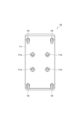
- FIG. 3 is a bottom view of the cart of FIG. 1;
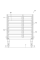
- FIG. 4 is a front view showing an example of the internal structure of the cart of FIG. 1.
- FIG. 5 is a perspective view of the station of FIG. 1;
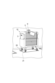
- FIG. 6 is a perspective view showing the automatic guided vehicle of FIG. 1.
- FIG. 7 is a perspective view showing a state in which the cover of the automatic guided vehicle of FIG. 1 is removed.
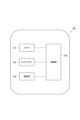
- FIG. 10 is a block diagram showing the configuration of the operating terminal.
- FIG. 11 is a diagram showing an example of a first transmission setting screen displayed on the operating terminal.
- FIG. 12(a) is a perspective view when reading the bar code of the station with the operation terminal.
- FIG. 12(b) is a perspective view when the two-dimensional code of the cart is read by the operation terminal.
- FIG. 13 is a diagram showing an example of a second transmission setting screen displayed on the operating terminal.
- FIG. 14 is a diagram showing an example of a third transmission setting screen displayed on the operating terminal.
- FIG. 15 is a perspective view when reading the two-dimensional code of the destination with the operation terminal.
- FIG. 16 is a diagram showing an example of a fourth transmission setting screen displayed on the operating terminal.
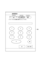
- FIG. 17 is a diagram showing an example of a fifth transmission setting screen displayed on the operating terminal.
- FIG. 18 is a diagram showing an example of a sixth transmission setting screen displayed on the operating terminal.
- FIG. 1 is a schematic configuration diagram showing a transport system 1 according to an embodiment.
- a transportation system 1 is installed indoors, for example, in a hospital, and is a system that realizes automatic transportation of carts (objects to be transported) 10 between a plurality of departments D.
- the transportation system 1 includes a plurality of carts 10 , a plurality of stations 20 , a plurality of automatic guided vehicles 30 , a system controller (controller) 40 , a plurality of access points 50 and a plurality of operation terminals 60 .
- FIG. 2 is a perspective view showing the cart 10 of FIG.
- FIG. 3 is a bottom view of cart 10 of FIG.
- FIG. 4 is a front view showing an example of the internal structure of the cart 10 of FIG.
- the cart 10 is a carriage for storing articles.
- the cart 10 is a cart unit having a rectangular shape in plan view (seen from above). In other words, the cart 10 is a rectangular dedicated cart for loading articles.
- the longitudinal direction of the cart 10 may be simply referred to as the "longitudinal direction”
- the lateral direction of the cart 10 may simply be referred to as the "transverse direction”.
- the cart 10 has a rectangular parallelepiped shape with a width of 800 mm, a length of 900 mm, and a height of 1400 mm.
- the cart 10 can also be used as a hand truck.
- the number of carts 10 used in the transport system 1 is not particularly limited, but may be 100 to 1000, for example.
- Articles stored in the cart 10 include, for example, specimens, injection drugs, sterilized instruments (sterilized containers, collection containers, etc.), medical materials (ME (Medical Engineering) instruments, etc.).
- the cart 10 has a housing 11, a handle 12, a shutter 13 and casters 14.
- the housing 11 has a rectangular box shape.
- An opening 11h is provided on one side of the housing 11 in the lateral direction.
- the inside of the housing 11 is accessible through the opening 11h.
- Inside the housing 11, for example, a plurality of tray receiving hooks for hooking and supporting edges of a tray TR containing articles are provided at appropriate positions.
- a placement plate for placing an article may be provided at an appropriate position inside the housing 11 .
- the bottom surface of the housing 11 is provided with a plurality of recesses 11x with which locate pins 32a (described later) of the automatic guided vehicle 30 are engaged.
- the recesses 11x are arranged on the bottom surface of the housing 11 at four vertex positions (90° rotationally symmetrical positions) of a square formed by sides along the longitudinal direction and the lateral direction.
- the handle 12 is, for example, the part that the user grips.
- the handle 12 is a rod-shaped member that extends vertically.
- the handles 12 are provided at four corners of the housing 11 at positions near the upper center in the vertical direction.
- the shutter 13 is provided so as to be able to close the opening 11h of the housing 11 .
- an up-and-down shutter is used in which a slat, which is formed by connecting elongated plate-like members in a bellows-like manner, is housed in the upper part.
- the shutter 13 is closed by lowering the slat from above, and is opened by lifting the slat from below.
- Casters 14 are provided at the four corners of the bottom surface of housing 11 .
- the caster 14 is configured to rotate 360° around an axis along the vertical direction.
- swivel casters are used, for example.
- FIG. 5 is a perspective view showing station 20 in FIG.
- station 20 is an area where carts 10 are placed.
- the stations 20 are demarcated by position markers 21 on the floor F.
- the station 20 presents a rectangular shape corresponding to the cart 10 in plan view.
- One cart 10 can be placed in the station 20 .
- a plurality of stations 20 are installed, for example, in one department D (see FIG. 1).
- the number of stations 20 installed in the transport system 1 is not particularly limited.
- FIG. 6 is a perspective view showing the automatic guided vehicle 30 of FIG.
- FIG. 7 is a perspective view showing a state in which the cover 31 of the automatic guided vehicle 30 of FIG. 1 is removed.
- FIG. 8 is a block diagram showing the configuration of the automatic guided vehicle 30 of FIG.
- FIG. 9 is a perspective view showing the cart 10 being transported by the automatic guided vehicle 30 of FIG.
- the automatic guided vehicle 30 is a guided vehicle that self-travels on the floor F along a predetermined travel route.
- the automatic guided vehicle 30 automatically conveys the cart 10 between the stations 20 .
- the predetermined travel route is a route set in advance and extends so as to pass between a plurality of departments D.
- the predetermined travel route is set, for example, so as to approach a plurality of stations 20 .
- the automatic guided vehicle 30 adopts a two-wheel speed difference system as a drive mechanism.
- the unmanned guided vehicle 30 is configured to be able to move forward, backward, turn left and right, and spin-turn (turn on the spot).
- the automatic guided vehicle 30 presents a rectangular outer shape in plan view.
- the automatic guided vehicle 30 has a rectangular parallelepiped shape with a width of 500 mm, a length of 700 mm, and a height of 320 mm.
- the number of automatic guided vehicles 30 used in the transport system 1 is not particularly limited, but may be 50, for example.
- the advancing direction of the automatic guided vehicle 30 may be simply referred to as "advancing direction”.
- a direction orthogonal to both the traveling direction and the vertical direction will be described as the “left-right direction”.
- the automatic guided vehicle 30 includes an elevator 32, an electric cylinder 33, a driving wheel 34, a motor 35, a driven wheel 36, a laser range finder 37, a guided vehicle controller 38, and a communication unit 39. have.
- the lift table 32 is a member on which the cart 10 is placed, and is configured to be liftable.
- the lifting platform 32 has a plate-like shape with a thickness extending in the vertical direction.
- the lift platform 32 is provided above the automatic guided vehicle 30 .
- a locating pin 32a is provided on the upper surface of the lifting platform 32 so as to protrude upward.
- the locating pin 32 a is a convex portion that engages with the concave portion 11 x on the bottom surface of the cart 10 placed on the lift table 32 .
- the upper portion of the locate pin 32a is tapered upward.
- the locating pins 32a are arranged on the upper surface of the lift table 32 at four vertex positions (90° rotationally symmetrical positions) of a square formed by sides along the advancing direction and the left-right direction.
- the lifting platform 32 lifts the cart 10 from below when ascending, and lowers the cart 10 to the floor F when descending.
- the electric cylinder 33 is a driving source for raising and lowering the lifting table 32 .
- the electric cylinder 33 is connected to a carrier controller 38 and its operation is controlled by the carrier controller 38 .
- the drive wheels 34 are wheels that drive the automatic guided vehicle 30 .
- a pair of drive wheels 34 are provided at the center of the automatic guided vehicle 30 in the traveling direction and at both ends in the left-right direction.
- a motor 35 is provided for each driving wheel 34 . That is, the pair of motors 35 are connected to the pair of drive wheels 34 respectively, and the pair of motors 35 drive the pair of drive wheels 34 independently.
- the motor 35 is connected to a carrier controller 38 and its operation is controlled by the carrier controller 38 .
- the unmanned guided vehicle 30 can spin-turn by rotating the pair of drive wheels 34 in different directions at a constant speed using the pair of motors 35 .
- the driven wheels 36 are wheels that are not driven and are rotated according to the driving of the drive wheels 34 .
- Two pairs of driven wheels 36 are provided.
- the driving wheels 34 are provided on one side of the automatic guided vehicle 30 in the direction of travel and at both ends in the left and right direction.
- a pair is provided at both ends in the direction.
- the driven wheel 36 is configured, for example, to rotate 360° around an axis extending in the vertical direction.
- the laser range finder 37 is a sensor that detects the surrounding environment of the automatic guided vehicle 30.
- the laser range finders 37 are provided on one side and the other side of the automatic guided vehicle 30 in the traveling direction. A pair of laser range finders 37 cooperate to obtain shape data of 360° around the automatic guided vehicle 30 .
- the laser range finder 37 is not particularly limited, and various sensors can be used as long as they can detect the surrounding environment of the automatic guided vehicle 30 .
- the laser range finder 37 is connected to the carrier controller 38 and outputs the detection result to the carrier controller 38 .
- the guided vehicle controller 38 comprehensively controls the automated guided vehicle 30 .
- the transport vehicle controller 38 is a computer including a CPU (Central Processing Unit), ROM (Read Only Memory), RAM (Random Access Memory), and the like.
- the carrier controller 38 can be configured as software in which, for example, a program stored in a ROM is loaded onto a RAM and executed by a CPU.
- the transport vehicle controller 38 may be configured as hardware such as an electronic circuit.
- the transport vehicle controller 38 may be composed of one device, or may be composed of a plurality of devices. When configured with a plurality of devices, these devices are connected via a communication network such as the Internet or an intranet to logically construct one transport vehicle controller 38 .
- the transport vehicle controller 38 performs travel control and loading/unloading control for transporting the cart 10 from the transport source station 20 to the transport destination station 20 based on the transport command received from the system controller 40 via the communication unit 39.
- SLAM Simultaneous Localization and Mapping
- self-position estimation is performed by comparing the created environment map with the surrounding shape data acquired by the laser range finder 37 .
- travel control the difference in self-position estimation with respect to the recognized self-position is received as a correction value, and travel of the unmanned guided vehicle 30 is controlled along the travel route from the self-position to the target position reflecting the correction value.
- the loading and unloading control loading and unloading of the unmanned guided vehicle 30 are performed by raising and lowering the elevator platform 32 .
- the communication unit 39 is a device that wirelessly communicates with the outside of the automatic guided vehicle 30 .
- the communication unit 39 communicates with the system controller 40 via the access point 50 .
- the communication unit 39 may include, for example, a wireless LAN antenna.
- the electric cylinder 33, the driving wheel 34, the motor 35, the driven wheel 36, the laser range finder 37, the guided vehicle controller 38, and the communication unit 39 are covered and protected by the cover 31 (see FIG. 6). there is
- such an unmanned guided vehicle 30 crawls under the cart 10 (between the cart 10 and the floor F), and raises the lift table 32 in this state to lift the cart 10. It is placed on a table 32 and lifted.
- the automatic guided vehicle 30 travels in a state in which the cart 10 is lifted from below by the lift platform 32 (a state in which the driven wheels 36 are separated from the floor F), thereby conveying the cart 10 .
- the unmanned guided vehicle 30 lowers the lift table 32 on which the cart 10 is placed, thereby bringing the cart 10 into contact with the floor F and unloading the cart 10 from the lift table 32 .
- the system controller 40 comprehensively controls the transport system 1.
- the system controller 40 is a computer comprising a CPU, ROM, RAM, and the like.
- the system controller 40 can be configured, for example, as software in which a program stored in the ROM is loaded onto the RAM and executed by the CPU.
- the system controller 40 may be configured as hardware such as an electronic circuit.
- the system controller 40 may be composed of one device, or may be composed of a plurality of devices. When configured with a plurality of devices, these devices are connected via a communication network such as the Internet or an intranet to logically construct one system controller 40 .
- the system controller 40 generates a transport command for transporting the cart 10 by the unmanned guided vehicle 30 based on an input (transport request) from the host controller (not shown) or the operation terminal 60 .
- the system controller 40 is installed, for example, in a server room.
- the transport command includes a travel route along which the automatic guided vehicle 30 is to travel.
- the transport pattern of the transport command includes normal transport, circular transport, and composite transport.
- Normal transportation is transportation in which the cart 10 is loaded onto the automated guided vehicle 30 at the source station 20 and the cart 10 is unloaded from the automated guided vehicle 30 at the destination station 20 .
- the cyclic transportation is transportation in which the cart 10 is loaded on the unmanned guided vehicle 30 at the station 20 of the transportation source, and after circulating the plurality of stations 20 while the cart 10 is placed thereon, the cart returns to the station 20 of the transportation source.
- round transportation the source of transportation and the destination of transportation are the same.
- the cart 10 is loaded onto an unmanned guided vehicle 30 at the source station 20 in the first section, moved to the second section, and unloaded at the destination station 20 in the second section.
- the cart 10 is loaded onto the automatic guided vehicle 30 at another station 20 in the second department, returned to the first department, and unloaded at the transport destination station 20 in the first department.
- the cart 10 may be unloaded at the transport destination station 20 in a department other than the first and second departments after being loaded onto the automatic guided vehicle 30 in the second department.
- the system controller 40 selects the optimum one from among the multiple automatic guided vehicles 30 using multiple conditions, and assigns a transport command to the selected automatic guided vehicle 30 .
- the plurality of conditions for selecting the automatic guided vehicle 30 are, for example, that the remaining battery level of the automatic guided vehicle 30 is equal to or greater than a predetermined value, that the distance from the transport source station 20 is the closest, and that another cart 10 is currently selected. Includes conditions such as not being transported.
- the access point 50 is a relay device for wireless communication between the system controller 40 and the automatic guided vehicle 30 and wireless communication between the system controller 40 and the operation terminal 60 .
- the access point 50 uses 2.4 GHz or 5 GHz as the frequency band.
- the access point 50 is wired to the system controller 40 via a cable CB.
- the number of access points 50 installed in the transport system 1 is not particularly limited.
- the access point 50 is provided on the ceiling surface or the wall surface.
- the operation terminal 60 is a terminal that receives inputs from the operator.
- Operation terminal 60 includes a touch panel.
- the operation terminal 60 is used to input the cart 10 to be transported, the input of the station 20 of the source of transport, the input of the station 20 of the transport destination, and the like.
- the operation terminal 60 is installed for each department D.
- FIG. A portable terminal such as a tablet terminal is used as the operation terminal 60 .
- One or a plurality of operation terminals 60 are assigned to one department D.
- FIG. Here, one operating terminal 60 is not assigned to a plurality of departments D.
- each of the plurality of carts 10 has a unique two-dimensional code (first ID) 3, as shown in FIGS.
- the two-dimensional code 3 is an identifier for identifying the cart 10 and is a matrix type code readable by the operation terminal 60 .
- the position where the two-dimensional code 3 is provided on the cart 10 is not particularly limited.
- the two-dimensional code 3 is provided on the outer surface (front surface and rear surface) of the housing 11 .
- Each of the plurality of stations 20 has a unique barcode (second ID) 6.
- the barcode 6 is an identifier for identifying the station 20 and is a one-dimensional code readable by the operation terminal 60 .
- the position where the barcode 6 is provided is not particularly limited.
- the bar code 6 is provided on the wall adjacent to the station 20 at a position not hidden by the cart 10 arranged at the station 20 .
- a label 4 is detachably attached to the cart 10 .
- the label 4 displays the transport destination of the cart 10 .
- the name of the destination department D is printed.
- the label 4 includes a two-dimensional code 5 relating to the destination department D.
- the two-dimensional code 5 is an identifier for identifying the destination of the cart 10 and is a matrix type code readable by the operation terminal 60 .
- the position where the label 4 is provided on the cart 10 is not particularly limited.
- the label 4 is provided on the outer surface (upper side surface) of the housing 11 .
- the operation terminal 60 is configured to be able to read the two-dimensional codes 3 and 5 and the barcode 6.
- the operation terminal 60 has a camera 61 , a touch panel (display screen) 62 , a communication section 63 and a control section 64 .
- the camera 61 is imaging equipment for reading (scanning) the two-dimensional codes 3 and 5 and the bar code 6 .
- the touch panel 62 is a device that allows an operator to perform various operations such as touch input and displays various information to the operator.
- the communication unit 63 is a device that communicates with the outside.
- the communication unit 63 communicates with the system controller 40 (see FIG. 1) via the access point 50 (see FIG. 1).
- the control unit 64 is a computer comprising a CPU, ROM, RAM, and the like.
- the control unit 64 can be configured as software in which a program stored in the ROM is loaded onto the RAM and executed by the CPU, for example.
- transmission setting a transmission setting for inputting the transport command
- the control unit 64 uses a pre-stored database or the like.
- the cart 10 corresponding to the two-dimensional code 3 is specified as a transport target. That is, the operating terminal 60 inputs the cart 10 to be transported by reading the two-dimensional code 3 in the transmission settings.
- control unit 64 When the control unit 64 recognizes the barcode 6 from the image captured by the camera 61 in the transmission settings, the control unit 64 refers to the database or the like to specify the station 20 corresponding to the barcode 6 as the transportation source. That is, the operating terminal 60 inputs the transport source station 20 by reading the barcode 6 in the transmission setting.
- the control unit 64 specifies the destination by the input method according to the selection result.
- the method of inputting the destination is "reading input” by the camera 61, "list selection” for selecting from a list of multiple destination candidates, “history input” for selecting from a plurality of destination histories, and "transportation destination”. Includes “ten-key input” that allows the operator to directly enter the number corresponding to .
- control unit 64 When the control unit 64 recognizes the two-dimensional code 5 from the image captured by the camera 61 when "reading input” is selected as the input method for the destination in the transmission settings, the control unit 64 refers to a database or the like. , the department D corresponding to the two-dimensional code 5 is specified as the destination. That is, the operating terminal 60 inputs the transport destination by reading the two-dimensional code 5 in the transmission settings.
- the control unit 64 displays a plurality of destination department D candidates on the touch panel 62 when "list channel selection" is selected as the destination input method in the transmission settings.
- the control unit 64 identifies the selected candidate department D as the transport destination. That is, in the transmission setting, the operation terminal 60 inputs the transport destination by selecting the transport destination candidate. Candidates for a plurality of destination departments D may be stored in advance in the control unit 64 .
- the control unit 64 displays the history of a plurality of destinations (a plurality of departments D that have been destinations in the past) on the touch panel 62 when "history input" is selected as the method of inputting destinations in the transmission settings. .
- the control unit 64 specifies the selected department D as the transport destination. That is, in the transmission setting, the operation terminal 60 inputs the destination by selecting it from the history of the destination.
- the transport destination history may be stored in the control unit 64 .
- the control unit 64 displays buttons 0 to 9 on the touch panel 62 when "numeric key input” is selected as the input method for the destination in the transmission settings.
- the control unit 64 identifies department D corresponding to the directly input number as the destination. That is, in the operation terminal 60, the transport destination is input by directly inputting the number by the operator in the transmission setting. Information about the number of the department D may be stored in the control unit 64 in advance.
- the control unit 64 transmits information about the cart 10, the destination, and the station 20 of the transportation source input (specified) via the touch panel 62 to the system controller 40 via the communication unit 63 as a transportation request. Details of the transmission settings will be described later.
- the operator uses, for example, the operation terminal 60 of the department D of the transportation source, and touches a button (icon) related to transmission settings on the main screen displayed on the touch panel 62 thereof.
- a button icon
- the screen is switched to the transmission setting screen shown in FIG.
- the process is divided in order from step 1 to step 3.
- a first transmission setting screen S1 for selecting the station 20 of the transportation source and the cart 10 of the transportation target is displayed on the touch panel 62 .
- the first transmission setting screen S1 includes a message prompting the operation terminal 60 to read the barcode 6 of the station 20 and the two-dimensional code 3 of the cart 10 .
- the image captured by the camera 61 is displayed on the first transmission setting screen S1.
- the source station 20 is displayed as the originating station, and the destination department D is displayed as the destination department (hereinafter the same).
- the operator uses the camera 61 of the operation terminal 60 to scan the barcode 6 of the station 20 of the transfer source, as shown in FIG. 12(a). read.
- the station 20 of the transfer source is entered, and the number of the station 20 of the transfer source is displayed on the first transmission setting screen S1.
- the operator uses the camera 61 of the operation terminal 60 to display the two-dimensional code 3 of the cart 10 to be transported, as shown in FIG. 12(b). to read.
- the cart 10 to be transported is entered, and the number of the cart 10 to be transported is displayed on the first transmission setting screen S1.
- the operator touches the "next" button on the first transmission setting screen S1, thereby completing the process of step 1.
- the operator can restart the process from the beginning of step 1 by touching the "return to beginning" button (hereinafter the same).
- a second transmission setting screen S2 for selecting the destination department is displayed on the touch panel 62 as a step 2 process.
- the second transmission setting screen S2 is a screen for selecting the input method of the destination.
- the second transmission setting screen S2 includes "reading input” by the camera 61, "list channel selection” for selecting from a list of candidates for a plurality of destinations, "input history” for selecting from a history of a plurality of destinations, and This is an operation screen that allows the operator to select one of the "ten-key input” methods, in which the operator directly inputs the corresponding number, as the method of inputting the destination.
- Reading input is a method of reading the destination department from the code.
- List channel selection is a method of selecting a destination department from a list of departments.
- History input is a method of selecting a destination department from the history.
- Teen-key input is a method of directly inputting the number of the destination department.
- the second transmission setting screen S2 includes a message prompting the user to select the method of inputting the destination. The operator touches one of these items on the second transmission setting screen S2 and touches the button "select destination station” to complete the selection of the input method for the destination.
- the third transmission setting screen S3 includes a message prompting the operation terminal 60 to read the two-dimensional code 5 on the cart 10 .
- the image captured by the camera 61 is displayed on the third transmission setting screen S3.
- the operator reads the two-dimensional code 5 with the camera 61 of the operation terminal 60, as shown in FIG.
- the destination department is entered, and the destination department number and the destination department name are displayed on the third transmission setting screen S3.
- the operator touches the "next" button on the third transmission setting screen S3, thereby completing the process of step 2.
- the fourth transmission setting screen S4 includes a message prompting the user to touch and select a destination department.
- the operator selects one from a list of destination department candidates. As a result, the destination department is entered. Then, the operator touches the "next" button on the fourth transmission setting screen S4, thereby completing the process of step 2.
- the second transmission setting screen S2 when "input history" is selected on the second transmission setting screen S2, transmission to select one from a list of destination departments (history of multiple destinations) in past transportation.
- a setting screen is displayed on the touch panel 62 .
- the operator selects a destination department from the history of transport destinations. As a result, the destination department is entered. Then, the operator touches the "next" button on the transmission setting screen, thereby completing the process of step 2.
- a fifth transmission setting screen S5 for touch-inputting the number of the destination department is displayed on the touch panel 62 as shown in FIG. Is displayed.
- the fifth transmission setting screen S5 includes a message prompting the user to enter the number of the destination department using the numeric keypad. Numeric buttons from 0 to 9 are displayed on the fifth transmission setting screen S5.
- the operator touch-inputs the number of the destination department. As a result, the destination department is entered. Then, the operator touches the "next" button on the fifth transmission setting screen S5, thereby completing the process of step 2.
- a sixth transmission setting screen S6 for confirming the contents (transmission contents) of the transport request to be transmitted is displayed on the touch panel 62.
- the sixth transmission setting screen S6 includes a message prompting confirmation of the transmission content and a message prompting determination if the transmission content is correct.
- the operator confirms the contents of transmission, and if there is no error, touches the "send decision" button on the sixth transmission setting screen S6. Then the process of step 3 is completed. After confirming the transmission contents, if there is an error, the operator can touch the "cancel" button on the sixth transmission setting screen S6 to cancel the transmission contents and restart the process from the beginning of step 1. It is possible.
- the operation terminal 60 transmits to the system controller 40 a transport request to transport the input cart 10 from the input station 20 to the input destination department. Then, the system controller 40 selects and allocates a transport command based on the transport request to an appropriate automatic guided vehicle 30 .
- the unmanned guided vehicle 30 to which the transport command is assigned starts automatic transport according to the transport command.
- the station 20 into which the cart 10 of the destination department is to be carried is automatically selected from a plurality of stations 20 of the destination department based on, for example, the mixed state of the destination departments.
- the cart 10 to be transported can be input by reading the two-dimensional code 3 instead of manual input, and the barcode 6 can be input instead of manual input.
- the station 20 of the transfer source can be input. Therefore, it is possible to reduce the time and effort required for the input and prevent erroneous input. That is, it is possible to easily input the transport command on the operation terminal 60 and prevent erroneous input.
- the operation terminal 60 is configured to be able to read the two-dimensional code 5 of the label 4 associated with the transport destination provided on the cart 10.
- the operation terminal 60 reads the two-dimensional code 5 of the label 4 when performing transmission settings.
- the transport destination can be input by reading the label 4 instead of manual input on the operation terminal 60 . It is possible to more easily perform transmission settings on the operation terminal 60 and to further prevent erroneous input.
- the operation terminal 60 is configured to be able to select one of the transport destination histories, and when inputting a transport command, the transport destination is input by selecting from the transport destination history. be. In this case, it is possible to input the destination department through the operation terminal 60 using the history of the destination department.
- the operation terminal 60 is configured to be able to select one of the candidates for the transport destination, and when inputting a transport command, the transport destination is input by selecting from the candidates for the transport destination. In this case, it is possible to input the destination department through the operation terminal 60 by using the candidates for the destination department.
- the operation terminal 60 is configured so that the number of the destination department can be directly input, and the operator directly inputs the number when inputting a transport command. In this case, it is possible to input the destination department through the operation terminal 60 by using the destination department number directly (manually) input by the operator.
- the object to be transported is the cart 10 .
- the effects described above can be obtained.
- the two-dimensional code 3 of the cart 10 to be transported and the destination department have already been input by a certain operation terminal 60 (first operation terminal) or another operation terminal 60 (second operation terminal). , the transmission settings have already been completed).
- the system controller 40 has transport information in which the two-dimensional code 3 and the destination department are associated.
- the transport information of the system controller 40 is used to display the destination department of the cart 10 on the touch panel 62 of the operation terminal 60.
- the two-dimensional code 3 is used as the first ID in the above embodiment, the first ID is not particularly limited, and various identifiers can be used.
- the barcode 6 is used as the second ID, but the second ID is not particularly limited, and various identifiers can be used.
- the position and size of the provided first ID are not limited, and similarly, the position and size of the provided second ID are not limited.
- the destination department is input by reading the two-dimensional code 5 on the label 4 with the operation terminal 60, but this is not the only option.
- an identifier different from the two-dimensional code 5 may be provided on the label 4 and read by the operation terminal 60 to input the destination department.
- the destination department may be input by reading letters, numbers, or a combination thereof written on the label 4 with the operation terminal 60 .
- the destination department may be input by reading labels (prescriptions, barcodes of electronic paper, etc.) of articles loaded on the cart 10 with the operation terminal 60 .
- the destination department may be input by reading the articles themselves loaded on the cart 10 with the operation terminal 60 .
- the destination department may be input by voice input to the operation terminal 60 .
- the position and size of the label 4 provided are not limited.
- the destination department is input via the operation terminal 60, but when returning the cart 10 to the department to which the cart belongs, for example, the destination department input may be omitted.
- the department to which the cart 10 belongs is set as the destination department D as it is.
- the department to which the cart 10 selected as the transport target belongs is automatically input as the transport destination by manual input or by reading the two-dimensional code 3 (first ID). may be
- the transported object is not particularly limited and may be various objects.
- the transport system 1 is applied to automatically transport carts 10 between a plurality of departments D, but the field to which one aspect of the present invention is applied is not particularly limited, and can be applied to various fields. .
- ⁇ Invention 1> a plurality of transferred objects each having a unique first ID and carrying articles; a plurality of stations each having a unique second ID and placing the transferred object; an automated guided vehicle that transports the object to be transported; an operation terminal that receives input from an operator; a controller that assigns a transport command based on an input received by the operation terminal to the automatic guided vehicle;
- the operation terminal is configured to be able to read the first ID and the second ID,
- the operation terminal is configured to be able to read a label relating to a destination provided on the article or the object to be conveyed, The conveying system according to invention 1, wherein when inputting the conveying command, the conveying destination is input by reading the label.
- the operation terminal is configured to be able to select one of a plurality of transport destination histories or candidates, The transport system according to invention 1, wherein when inputting the transport command, a transport destination is input by selecting from transport destination history or candidates.
- the operation terminal is configured so that the operator can directly enter numbers, letters, or a combination of these relating to the destination,
- the transportation system according to the invention 1 wherein when inputting the transportation command, the transportation destination is input by directly inputting the number, the letter, or a combination thereof by the operator.
- ⁇ Invention 5> When the first ID is read by the first operating terminal which is the operating terminal, the transport destination of the transported object corresponding to the read first ID is already the first operating terminal or the first operating terminal.
- the transportation according to any one of Inventions 2 to 4 wherein information about the transportation destination is displayed on the display screen of the first operation terminal when input is made on a second operation terminal that is another operation terminal.
- ⁇ Invention 6> The conveying system according to any one of inventions 1 to 5, wherein the object to be conveyed is a cart on which articles are loaded.
Landscapes
- Engineering & Computer Science (AREA)
- Aviation & Aerospace Engineering (AREA)
- Radar, Positioning & Navigation (AREA)
- Remote Sensing (AREA)
- Physics & Mathematics (AREA)
- General Physics & Mathematics (AREA)
- Automation & Control Theory (AREA)
- Control Of Position, Course, Altitude, Or Attitude Of Moving Bodies (AREA)
Abstract
搬送システムは、それぞれに固有の第1IDを有し、物品を積載する複数の被搬送物と、それぞれに固有の第2IDを有し、被搬送物を配置する複数のステーションと、被搬送物を搬送する無人搬送車と、オペレータからの入力を受け付ける操作端末と、操作端末で受け付けた入力に基づく搬送指令を無人搬送車に割り付けるコントローラと、を備える。操作端末は、第1ID及び第2IDを読み取り可能に構成される。操作端末は、搬送指令に関する入力を行う場合に、第1IDを読み取ることで搬送対象となる被搬送物が入力され、第2IDを読み取ることで搬送元のステーションが入力される。
Description
本発明の一側面は、搬送システムに関する。
被搬送物と、被搬送物を配置するステーションと、被搬送物を搬送する無人搬送車と、オペレータからの入力を受け付ける操作端末と、操作端末で受け付けた入力に基づく搬送指令を無人搬送車に割り付けるコントローラと、を備えた搬送システムが知られている。この種の技術として、例えば特許文献1には、ワゴン台車(被搬送物)の下方に潜り込んでワゴン台車をリフトアップする無人車を備え、外部から指示された目的地まで無人車によりワゴン台車を搬送するシステムが開示されている。
上述したような搬送システムでは、通常、操作端末において搬送指令に関する入力を行う際、搬送対象となる被搬送物の指定及び搬送元のステーションの指定がオペレータの手入力(直接入力)でなされる。そのため、当該入力に手間がかかるおそれ、及び、当該入力を誤入力してしまうおそれがある。
そこで、本発明の一側面は、操作端末における搬送指令に関する入力を簡便に行い且つ誤入力を防ぐことが可能な搬送システムを提供することを目的とする。
本発明の一側面に係る搬送システムは、それぞれに固有の第1IDを有し、物品を積載する複数の被搬送物と、それぞれに固有の第2IDを有し、被搬送物を配置する複数のステーションと、被搬送物を搬送する無人搬送車と、オペレータからの入力を受け付ける操作端末と、操作端末で受け付けた入力に基づく搬送指令を無人搬送車に割り付けるコントローラと、を備え、操作端末は、第1ID及び第2IDを読み取り可能に構成され、搬送指令に関する入力を行う場合に、第1IDを読み取ることで搬送対象となる被搬送物が入力され、第2IDを読み取ることで搬送元のステーションが入力される。
この搬送システムでは、操作端末において搬送指令に関する入力を行う場合、手入力ではなく第1IDを読み取ることで、搬送対象の当該搬送物を入力することができると共に、手入力ではなく第2IDを読み取ることで、搬送元のステーションを入力することができる。よって、当該入力にかかる手間を抑え、且つ、誤入力を防ぐことが可能となる。すなわち、操作端末における搬送指令に関する入力を簡便に行い且つ誤入力を防ぐことが可能となる。
本発明の一側面に係る搬送システムでは、操作端末は、物品又は被搬送物に設けられた搬送先に関するラベルを読み取り可能に構成され、搬送指令に関する入力を行う場合に、当該ラベルを読み取ることで搬送先が入力されてもよい。この場合、操作端末において、手入力ではなくラベルを読み取ることで、搬送先を入力することができる。操作端末における搬送指令に関する入力を、一層簡便に行い且つ誤入力を一層防ぐことが可能となる。
本発明の一側面に係る搬送システムでは、操作端末は、複数の搬送先の履歴又は候補の中から何れかを選択可能に構成され、搬送指令に関する入力を行う場合に、搬送先の履歴又は候補より選択されることで搬送先が入力されてもよい。この場合、搬送先の履歴又は候補を利用して、搬送先を操作端末にて入力することが可能となる。
本発明の一側面に係る搬送システムでは、操作端末は、搬送先に関する番号をオペレータが直接入力可能に構成され、搬送指令に関する入力を行う場合に、当該番号がオペレータにより直接入力されることで搬送先が入力されてもよい。この場合、オペレータにより直接入力された搬送先に関する番号を利用して、搬送先を操作端末にて入力することが可能となる。
本発明の一側面に係る搬送システムは、操作端末である第1操作端末で第1IDが読み取られた場合、読み取られた第1IDに対応する被搬送物の搬送先が既に第1操作端末もしくは第1操作端末とは別の操作端末である第2操作端末にて入力されているときには、当該搬送先に関する情報を第1操作端末の表示画面に表示してもよい。この場合、例えば無人搬送車による被搬送物の搬送中にトラブル等が発生し、スタッフ等が被搬送物を運搬(人手で運搬)する必要があるときに、スタッフ等は、第1操作端末で第1IDを読み込むことで、その表示画面に当該被搬送物の搬送先を表示させて確認することが可能となる。
本発明の一側面に係る搬送システムでは、被搬送物は、物品を積載するカートであってもよい。この場合、無人搬送車によりカートを搬送させるシステムにおいて、上述の効果を奏することができる。
本発明の一側面によれば、操作端末における搬送指令に関する入力を簡便に行い且つ誤入力を防ぐことが可能な搬送システムを提供することが可能となる。
以下、図面を参照して、実施形態について説明する。図面の説明において、同一要素には同一符号を付し、重複する説明を省略する。「上」及び「下」の語は、鉛直方向の上下方向に対応する。
図1は、実施形態に係る搬送システム1を示す概略構成図である。図1に示されるように、搬送システム1は、例えば病院等の屋内に設置され、複数の部署D間におけるカート(被搬送物)10の自動搬送を実現するシステムである。搬送システム1は、複数のカート10、複数のステーション20、複数の無人搬送車30、システムコントローラ(コントローラ)40、複数のアクセスポイント50及び複数の操作端末60を備える。
図2は、図1のカート10を示す斜視図である。図3は、図1のカート10を示す底面図である。図4は、図1のカート10の内部構造の例を示す正面図である。図2及び図4に示されるように、カート10は、物品を収容する台車である。カート10は、平面視(上方から見て)で矩形形状を呈するカートユニットである。換言すると、カート10は、物品を積載する矩形の専用カートである。以下、カート10の長手方向を単に「長手方向」といい、カート10の短手方向を単に「短手方向」という場合もある。
例えばカート10は、幅800mm、長さ900mm、高さ1400mmの直方体状の外形を呈する。カート10は、手押し台車としても使用可能である。搬送システム1で用いられるカート10の台数は特に限定されないが、例えば100台~1000台であってもよい。カート10に収容される物品としては、例えば、検体、注射薬、滅菌器材(滅菌コンテナ及び回収コンテナ等)、診療材料(ME(Medical Engineering)機器等)が挙げられる。
カート10は、筐体11、把手12、シャッター13及びキャスター14を有する。筐体11は、矩形箱状の外形を呈する。短手方向における筐体11の一方側には、開口部11hが設けられている。筐体11では、その内部に開口部11hを介してアクセス可能である。筐体11の内部には、例えば物品を入れたトレーTRの縁を引っ掛けて支持する複数のトレー受けフックが、適宜な位置に設けられている。なお、筐体11の内部には、物品を載置する載置板が適宜な位置に設けられていてもよい。図3に示されるように、筐体11の底面には、無人搬送車30のロケートピン32a(後述)が係合する凹部11xが、複数設けられている。凹部11xは、筐体11の底面において、長手方向及び短手方向に沿った辺で構成された正方形の4つの頂点位置(90°回転対称位置)に配置されている。
図2に示されるように、把手12は、例えばユーザが握る部分である。把手12は、上下方向に延びる棒状の部材である。把手12は、筐体11の四隅において上下方向の中央部上寄りの位置に設けられている。シャッター13は、筐体11の開口部11hを閉塞可能に設けられている。シャッター13としては、例えば、細長い板状部材が蛇腹状に連なって成るスラットを上部に収納する上下シャッターが用いられている。シャッター13は、スラットを上方から下方に降ろすことで閉状態とする一方、スラットを下方から上方に持ち上げることで開状態とする。キャスター14は、筐体11の下面の四隅に設けられている。キャスター14は、上下方向に沿う軸回りに360°回転するように構成されている。キャスター14としては、例えば自在キャスターが用いられている。
図5は、図1のステーション20を示す斜視図である。図5に示されるように、ステーション20は、カート10を配置するエリアである。ステーション20は、床Fのポジションマーカ21により区画されている。ステーション20は、平面視においてカート10に対応する矩形形状を呈する。ステーション20には、1台のカート10が配置可能である。ステーション20は、例えば1つの部署D(図1参照)において複数設置されている。搬送システム1で設置されるステーション20の数は特に限定されない。
図6は、図1の無人搬送車30を示す斜視図である。図7は、図1の無人搬送車30のカバー31を外した状態を示す斜視図である。図8は、図1の無人搬送車30の構成を示すブロック図である。図9は、図1の無人搬送車30によるカート10の搬送時を示す斜視図である。図6に示されるように、無人搬送車30は、所定の走行経路に沿って床F上を自走する搬送車である。無人搬送車30は、複数のステーション20間においてカート10を自動搬送する。所定の走行経路は、予め設定された経路であって、複数の部署D間を通るように延びる。所定の走行経路は、例えば複数のステーション20に近接するように設定される。
無人搬送車30は、駆動機構として2輪速度差方式を採用する。無人搬送車30は、前進、後退、左右折及びスピンターン(その場での旋回)が可能に構成されている。無人搬送車30は、平面視で矩形形状の外形を呈する。例えば無人搬送車30は、幅500mm、長さ700mm、高さ320mmの直方体状の外形を呈する。搬送システム1で用いられる無人搬送車30の数は特に限定されないが、例えば50台であってもよい。以下、無人搬送車30の進行方向を単に「進行方向」という場合もある。進行方向及び上下方向の両者と直交する方向を「左右方向」として説明する。
図7及び図8に示されるように、無人搬送車30は、昇降台32、電動シリンダ33、駆動輪34、モータ35、従動輪36、レーザレンジファインダ37、搬送車コントローラ38及び通信部39を有する。
昇降台32は、カート10を載置する部材であり、昇降可能に構成されている。昇降台32は、上下方向を厚さ方向とする板状を呈する。昇降台32は、無人搬送車30の上部に設けられている。昇降台32の上面には、上方に突出するロケートピン32aが設けられている。ロケートピン32aは、昇降台32に載置されたカート10の底面の凹部11xと係合する凸部である。ロケートピン32aの上部は、上方へ先細りとなるようなテーパ状を呈する。ロケートピン32aは昇降台32の上面において、進行方向及び左右方向に沿った辺で構成された正方形の4つの頂点位置(90°回転対称位置)に配置されている。昇降台32は、上昇時にカート10を下から持ち上げ、下降時にカート10を床Fに降ろす。電動シリンダ33は、昇降台32を昇降させる駆動源である。電動シリンダ33は、搬送車コントローラ38に接続されており、その動作が搬送車コントローラ38により制御される。
駆動輪34は、無人搬送車30を駆動する車輪である。駆動輪34は、進行方向における無人搬送車30の中央であって左右方向の両端部に、一対設けられている。モータ35は、駆動輪34毎に設けられている。つまり、一対のモータ35が一対の駆動輪34のそれぞれに接続され、一対のモータ35が一対の駆動輪34のそれぞれを独立して駆動する。モータ35は、搬送車コントローラ38に接続されており、その動作が搬送車コントローラ38により制御される。例えば一対のモータ35により一対の駆動輪34を互いに異なる方向に等速回転駆動させることで、無人搬送車30のスピンターンが可能である。
従動輪36は、駆動を行わない車輪であって、駆動輪34の駆動に応じて回転させられる車輪である。従動輪36は、二対設けられている。具体的には、駆動輪34は、進行方向における無人搬送車30の一方側であって左右方向の両端部に一対設けられていると共に、進行方向における無人搬送車30の他方側であって左右方向の両端部に一対設けられている。従動輪36は、例えば上下方向に沿う軸回りに360°回転するように構成されている。
レーザレンジファインダ37は、無人搬送車30の周囲環境を検出するセンサである。レーザレンジファインダ37は、進行方向における無人搬送車30の一方側及び他方側に設けられている。一対のレーザレンジファインダ37は、協働して無人搬送車30の周囲360°の形状データを取得する。レーザレンジファインダ37としては特に限定されず、無人搬送車30の周囲環境を検出できれば、種々のセンサを用いることができる。レーザレンジファインダ37は、搬送車コントローラ38に接続されており、その検出結果を搬送車コントローラ38へ出力する。
搬送車コントローラ38は、無人搬送車30を統括的に制御する。搬送車コントローラ38は、CPU(Central Processing Unit)、ROM(Read Only Memory)及びRAM(Random Access Memory)等からなるコンピュータである。搬送車コントローラ38は、例えばROMに格納されているプログラムがRAM上にロードされてCPUで実行されるソフトウェアとして構成することができる。搬送車コントローラ38は、電子回路等によるハードウェアとして構成されてもよい。搬送車コントローラ38は、一つの装置で構成されてもよいし、複数の装置で構成されてもよい。複数の装置で構成されている場合には、これらがインターネット又はイントラネット等の通信ネットワークを介して接続されることで、論理的に一つの搬送車コントローラ38が構築される。
搬送車コントローラ38は、システムコントローラ40から通信部39を介して受信した搬送指令に基づき、搬送元のステーション20から搬送先のステーション20へカート10を搬送させるための走行制御及び荷積み荷下ろし制御を実行する。走行制御では、誘導方式としてSLAM(Simultaneous Localization and Mapping)技術を利用している。走行制御では、作成された環境地図とレーザレンジファインダ37で取得した周囲の形状データとを照らし合わせることで、自己位置推定を行う。走行制御では、認識している自己位置に対して自己位置推定の差分を補正値として受け取り、補正値を反映した自己位置から目標位置までの走行ルートに沿って、無人搬送車30の走行を制御する。荷積み荷下ろし制御では、昇降台32を上昇及び下降させることで、無人搬送車30への荷積み及び無人搬送車30からの荷下ろしを実施する。
通信部39は、無人搬送車30の外部との間で無線で通信を行う機器である。通信部39は、アクセスポイント50を介してシステムコントローラ40との間で通信を行う。通信部39は、例えば無線LANアンテナを含んでいてもよい。無人搬送車30では、電動シリンダ33、駆動輪34、モータ35、従動輪36、レーザレンジファインダ37、搬送車コントローラ38及び通信部39は、カバー31(図6参照)に覆われて保護されている。
このような無人搬送車30は、図9に示されるように、カート10の下方(カート10と床Fとの間)に潜り込み、その状態で昇降台32を上昇させることにより、カート10を昇降台32に載置して持ち上げる。無人搬送車30は、カート10を昇降台32で下から持ち上げた状態(従動輪36を床Fから離間させた状態)で走行し、これにより、カート10を搬送する。一方、無人搬送車30は、カート10を載置した昇降台32を下降させることにより、カート10を床Fに接地させて昇降台32からカート10を降ろす。
図1に戻り、システムコントローラ40は、搬送システム1を統括的に制御する。システムコントローラ40は、CPU、ROM及びRAM等からなるコンピュータである。システムコントローラ40は、例えばROMに格納されているプログラムがRAM上にロードされてCPUで実行されるソフトウェアとして構成することができる。システムコントローラ40は、電子回路等によるハードウェアとして構成されてもよい。システムコントローラ40は、一つの装置で構成されてもよいし、複数の装置で構成されてもよい。複数の装置で構成されている場合には、これらがインターネット又はイントラネット等の通信ネットワークを介して接続されることで、論理的に一つのシステムコントローラ40が構築される。
システムコントローラ40は、不図示の上位コントローラ又は操作端末60からの入力(搬送要求)に基づいて、無人搬送車30によりカート10を搬送させる搬送指令を生成する。システムコントローラ40は、例えばサーバルーム等に設置される。搬送指令には、無人搬送車30を走行させる走行ルートが含まれる。搬送指令の搬送パターンとしては、通常搬送、巡回搬送及び複合搬送を含む。
通常搬送は、搬送元のステーション20でカート10を無人搬送車30に荷積みし、搬送先のステーション20でカート10を無人搬送車30から荷下ろしする搬送である。巡回搬送は、搬送元のステーション20でカート10を無人搬送車30に荷積みし、カート10を載せたまま複数のステーション20を巡回した後、搬送元のステーション20に戻る搬送である。巡回搬送では、搬送元と搬送先とは一致する。複合搬送は、第1部署における搬送元のステーション20でカート10を無人搬送車30に荷積みし、第2部署へ移動し、第2部署における搬送先のステーション20にカート10を荷下ろすと共に、第2部署における他のステーション20でカート10を無人搬送車30に荷積みし、第1部署へ戻り、第1部署における搬送先のステーション20にカート10を荷下ろす搬送である。なお、複合搬送では、第2部署において無人搬送車30に荷積みした後に、第1部署及び第2部署以外の部署における搬送先のステーション20にカート10を荷下ろしてもよい。
システムコントローラ40は、複数の無人搬送車30の中から、複数の条件を用いて最適な何れかを選択し、選択した無人搬送車30に搬送指令を割り付ける。無人搬送車30を選択するための複数条件は、例えば、無人搬送車30のバッテリー残量が所定値以上である、搬送元のステーション20からの距離が最も近い、及び、他のカート10を現在搬送中ではない、等の条件を含む。
アクセスポイント50は、システムコントローラ40と無人搬送車30との間の無線通信、及び、システムコントローラ40と操作端末60との間の無線通信を行うための中継機器である。例えばアクセスポイント50では、2.4GHz又は5GHzが利用周波数帯域とされる。アクセスポイント50は、ケーブルCBを介してシステムコントローラ40に有線接続されている。搬送システム1で設置されるアクセスポイント50の数は特に限定されない。アクセスポイント50は、天井面又は壁面に設けられる。
操作端末60は、オペレータからの入力を受け付ける端末である。操作端末60は、タッチパネルを含む。操作端末60では、搬送対象となるカート10の入力、搬送元のステーション20の入力、及び、搬送先のステーション20の入力等がなされる。操作端末60は、部署Dごとに設置されている。操作端末60としては、タブレット端末等の可搬型端末が用いられている。操作端末60は、1つの部署Dに対して1又は複数台割り当てられている。ここでは、操作端末60は、複数の部署Dに対して1台割り当てられることはない。
本実施形態の搬送システム1において、図2及び図5に示されるように、複数のカート10のそれぞれは、固有の二次元コード(第1ID)3を有する。二次元コード3は、カート10を識別するための識別子であり、操作端末60で読取り可能なマトリクス式のコードである。カート10において二次元コード3が設けられる位置は特に限定されない。例えば二次元コード3は、筐体11の外面(前面及び後面)に設けられている。
複数のステーション20のそれぞれは、固有のバーコード(第2ID)6を有する。バーコード6は、ステーション20を識別するための識別子であり、操作端末60で読取り可能な一次元コードである。バーコード6が設けられる位置は特に限定されない。例えばバーコード6は、ステーション20に近接する壁面において、ステーション20に配置されているカート10に隠れない位置に設けられている。
カート10には、ラベル4が取付け及び取外し可能に設けられている。ラベル4は、カート10の搬送先を表示する。ラベル4には、搬送先の部署Dの名称が印字されている。ラベル4は、搬送先の部署Dに関する二次元コード5を含む。二次元コード5は、カート10の搬送先を識別するための識別子であり、操作端末60で読取り可能なマトリクス式のコードである。カート10においてラベル4が設けられる位置は特に限定されない。例えばラベル4は、筐体11の外面(上部の側面)に設けられている。
図10に示されるように、操作端末60は、二次元コード3,5及びバーコード6を読取り可能に構成されている。操作端末60は、カメラ61、タッチパネル(表示画面)62、通信部63及び制御部64を有する。カメラ61は、二次元コード3,5及びバーコード6を読み取る(スキャンする)ための撮像機器である。タッチパネル62は、オペレータからのタッチ入力等の各種操作がなされると共に、オペレータへの各種情報を表示する機器である。通信部63は、外部との間で通信を行う機器である。通信部63は、アクセスポイント50(図1参照)を介してシステムコントローラ40(図1参照)と通信する。
制御部64は、CPU、ROM及びRAM等からなるコンピュータである。制御部64は、例えばROMに格納されているプログラムがRAM上にロードされてCPUで実行されるソフトウェアとして構成することができる。制御部64は、搬送指令に関する入力を行う送信設定(以下、単に「送信設定」ともいう)において、カメラに61に映された画像から二次元コード3を認識した場合、予め記憶されたデータベース等を参照して、当該二次元コード3に対応するカート10を搬送対象として特定する。すなわち、操作端末60は、送信設定において、二次元コード3を読み取ることで搬送対象となるカート10が入力される。
制御部64は、送信設定において、カメラ61に映された画像からバーコード6を認識した場合、データベース等を参照して、バーコード6に対応するステーション20を搬送元として特定する。すなわち、操作端末60は、送信設定において、バーコード6を読み取ることで搬送元のステーション20が入力される。
制御部64は、送信設定において、搬送先の入力方法が操作端末60にて選択された場合、その選択結果に応じた入力方法で搬送先を特定する。搬送先の入力方法は、カメラ61による「読取入力」、複数の搬送先の候補の一覧から選択させる「一覧選局」、複数の搬送先の履歴から選択させる「履歴入力」、及び、搬送先に対応する番号をオペレータから直接入力させる「テンキー入力」を含む。
制御部64は、送信設定において、「読取入力」が搬送先の入力方法に選択されたときに、カメラに61に写された画像から二次元コード5を認識した場合、データベース等を参照して、二次元コード5に対応する部署Dを搬送先として特定する。すなわち、操作端末60は、送信設定において、二次元コード5を読み取ることで搬送先が入力される。
制御部64は、送信設定において、「一覧選局」が搬送先の入力方法に選択されたときに、複数の搬送先の部署Dの候補をタッチパネル62に表示する。制御部64は、タッチパネル62において複数の部署Dの候補の何れかがオペレータによりタッチされて選択された場合、選択された候補の部署Dを搬送先として特定する。すなわち、操作端末60は、送信設定において、搬送先の候補より選択されることで搬送先が入力される。複数の搬送先の部署Dの候補は、制御部64に予め記憶されていてもよい。
制御部64は、送信設定において、「履歴入力」が搬送先の入力方法に選択されたときに、複数の搬送先の履歴(過去に搬送先とした複数の部署D)をタッチパネル62に表示する。制御部64は、タッチパネル62において、履歴における複数の部署Dの何れかがオペレータによりタッチされて選択された場合、選択された部署Dを搬送先として特定する。すなわち、操作端末60は、送信設定において、搬送先の履歴より選択されることで搬送先が入力される。搬送先の履歴は、制御部64に記憶されていてもよい。
制御部64は、送信設定において、「テンキー入力」が搬送先の入力方法に選択されたときに、0~9までのボタンをタッチパネル62に表示する。制御部64は、タッチパネル62において、0~9までのボタンを利用して番号が直接入力された場合、直接入力された番号に対応する部署Dを搬送先として特定する。すなわち、操作端末60は、送信設定において、番号がオペレータにより直接入力されることで搬送先が入力される。部署Dの番号に関する情報は、制御部64に予め記憶されていてもよい。
制御部64は、タッチパネル62を介して入力(特定)されたカート10、搬送先、及び搬送元のステーション20に関する情報を、搬送要求として通信部63を介してシステムコントローラ40へ送信する。送信設定の詳細については、後述する。
次に、カート10を搬送元のステーション20から搬送先の部署Dへ搬送するための送信設定の一例について、具体的に説明する。
オペレータは、例えば搬送元の部署Dの操作端末60を用い、そのタッチパネル62に表示されたメイン画面において、送信設定に関するボタン(アイコン)をタッチする。これにより、図11に示される送信設定用の画面に切り替える。送信設定では、その工程がステップ1からステップ3の順に分かれている。
まず、送信設定では、ステップ1の工程として、搬送元のステーション20及び搬送対象のカート10を選局するための第1送信設定画面S1が、タッチパネル62に表示される。第1送信設定画面S1は、ステーション20のバーコード6及びカート10の二次元コード3を操作端末60で読み取ることを促すメッセージを含む。第1送信設定画面S1では、カメラ61に映る映像を表示する。第1送信設定画面S1では、搬送元のステーション20が発ステーションと表示され、搬送先の部署Dが行先部署と表示される(以下、同じ)。
第1送信設定画面S1がタッチパネル62上に表示されるのに応じて、オペレータは、図12(a)に示されるように、操作端末60のカメラ61により搬送元のステーション20のバーコード6を読み取る。これにより、搬送元のステーション20が入力され、第1送信設定画面S1には、搬送元のステーション20の番号が表示される。
第1送信設定画面S1がタッチパネル62上に表示されるのに応じて、オペレータは、図12(b)に示されるように、操作端末60のカメラ61により搬送対象のカート10の二次元コード3を読み取る。これにより、搬送対象のカート10が入力され、第1送信設定画面S1には、搬送対象のカート10の番号が表示される。そして、オペレータは、第1送信設定画面S1の「次へ」のボタンをタッチすることで、ステップ1の工程が完了する。なお、オペレータは、「始めに戻る」のボタンをタッチすることで、ステップ1の工程の始めからやり直すことが可能である(以下、同じ)。
続いて、通信設定では、ステップ2の工程として、図13に示されるように、行先部署を選局するための第2送信設定画面S2がタッチパネル62に表示される。第2送信設定画面S2は、搬送先の入力方法を選択するための画面である。第2送信設定画面S2は、カメラ61による「読取入力」、複数の搬送先の候補の一覧から選択させる「一覧選局」、複数の搬送先の履歴から選択させる「履歴入力」、及び、搬送先に対応する番号をオペレータから直接入力させる「テンキー入力」のうちの何れかを、搬送先の入力方法として選択させる操作画面である。
「読取入力」は、行先部署をコードから読み取る方法である。「一覧選局」は、部署の一覧から行先部署を選ぶ方法である。「履歴入力」は、行先部署を履歴から選ぶ方法である。「テンキー入力」は、行先部署の番号を直接入力する方法である。第2送信設定画面S2は、搬送先の入力方法を選択することを促すメッセージを含む。オペレータは、第2送信設定画面S2において、これらの何れかをタッチし、「行先部署選局へ」のボタンをタッチすることで、搬送先の入力方法を選択が完了する。
通信設定では、第2送信設定画面S2で「読取入力」が選択された場合、図14に示されるように、搬送先に対応する二次元コード5を読み取るための第3送信設定画面S3がタッチパネル62に表示される。第3送信設定画面S3は、カート10の二次元コード5を操作端末60で読み取ることを促すメッセージを含む。第3送信設定画面S3では、カメラ61に映る映像を表示する。第3送信設定画面S3がタッチパネル62上に表示されるのに応じて、オペレータは、図15に示されるように、操作端末60のカメラ61により二次元コード5を読み取る。これにより、行先部署が入力され、第3送信設定画面S3には、行先部署の番号と行先部署の名称とが表示される。そして、オペレータは、第3送信設定画面S3の「次へ」のボタンをタッチすることで、ステップ2の工程が完了する。
或いは、通信設定では、第2送信設定画面S2で「一覧選局」が選択された場合、図16に示されるように、複数の行先部署の候補の一覧から何れかを選択させる第4送信設定画面S4がタッチパネル62に表示される。第4送信設定画面S4は、行先部署をタッチさせて選ばせることを促すメッセージを含む。第4送信設定画面S4がタッチパネル62上に表示されるのに応じて、オペレータは、複数の行先部署の候補の一覧から何れかを選択する。これにより、行先部署が入力される。そして、オペレータは、第4送信設定画面S4の「次へ」のボタンをタッチすることで、ステップ2の工程が完了する。
また或いは、通信設定では、第2送信設定画面S2で「履歴入力」が選択された場合、過去の搬送において行先部署とした部署の一覧(複数の搬送先の履歴)から何れかを選択させる送信設定画面がタッチパネル62に表示される。当該送信設定画面がタッチパネル62上に表示されるのに応じて、オペレータは、搬送先の履歴から行先部署を選択する。これにより、行先部署が入力される。そして、オペレータは、当該送信設定画面の「次へ」のボタンをタッチすることで、ステップ2の工程が完了する。
また或いは、通信設定では、第2送信設定画面S2で「テンキー入力」が選択された場合、図17に示されるように、行先部署の番号をタッチ入力させる第5送信設定画面S5がタッチパネル62に表示される。第5送信設定画面S5は、テンキーから行先部署の番号を入力させることを促すメッセージを含む。第5送信設定画面S5では、0~9までの数字のボタンを表示する。第5送信設定画面S5がタッチパネル62上に表示されるのに応じて、オペレータは、行先部署の番号をタッチ入力する。これにより、行先部署が入力される。そして、オペレータは、第5送信設定画面S5の「次へ」のボタンをタッチすることで、ステップ2の工程が完了する。
続いて、通信設定では、ステップ3の工程として、図18に示されるように、送信する搬送要求に係る内容(送信内容)を確認するための第6送信設定画面S6が、タッチパネル62に表示される。第6送信設定画面S6は、送信内容を確認することを促すメッセージ、及び、送信内容に間違いなければ決定することを促すメッセージを含む。第6送信設定画面S6がタッチパネル62上に表示されるのに応じて、オペレータは、送信内容を確認した後、間違いなければ、第6送信設定画面S6の「送信決定」のボタンをタッチすることで、ステップ3の工程が完了する。なお、オペレータは、送信内容を確認した後、間違いがあれば、第6送信設定画面S6の「取消」のボタンをタッチすることで、送信内容を取り消し、ステップ1の工程の始めからやり直すことが可能である。
ステップ3の工程が完了後、操作端末60は、入力されたステーション20から、入力されたカート10を、入力された行先部署まで搬送させる搬送要求を、システムコントローラ40へ送信する。そして、システムコントローラ40は、搬送要求に基づく搬送指令を、適切な無人搬送車30を選択して割り付ける。搬送指令が割り付けられた無人搬送車30は、当該搬送指令に応じた自動搬送を開始する。ちなみに、搬送指令において、行先部署のカート10を搬入するステーション20は、例えば行先部署の混在状況等に基づいて、行先部署の複数のステーション20から自動選択される。
以上、搬送システム1では、操作端末60において送信設定を行う場合、手入力ではなく二次元コード3を読み取ることで、搬送対象のカート10を入力することができると共に、手入力ではなくバーコード6を読み取ることで、搬送元のステーション20を入力することができる。よって、当該入力にかかる手間を抑え、且つ、誤入力を防ぐことが可能となる。すなわち、操作端末60における搬送指令に関する入力を簡便に行い且つ誤入力を防ぐことが可能となる。
搬送システム1では、操作端末60は、カート10に設けられた搬送先に関するラベル4の二次元コード5を読み取り可能に構成される。操作端末60は、送信設定を行う場合に、ラベル4の二次元コード5を読み取る。この場合、操作端末60において、手入力ではなくラベル4を読み取ることで、搬送先を入力することができる。操作端末60における送信設定を一層簡便に行い且つ誤入力を一層防ぐことが可能となる。
搬送システム1では、操作端末60は、搬送先の履歴の中から何れかを選択可能に構成され、搬送指令に関する入力を行う場合に、搬送先の履歴より選択されることで搬送先が入力される。この場合、行先部署の履歴を利用して、行先部署を操作端末60にて入力することが可能となる。操作端末60は、搬送先の候補の中から何れかを選択可能に構成され、搬送指令に関する入力を行う場合に、搬送先の候補より選択されることで搬送先が入力される。この場合、行先部署の候補を利用して、行先部署を操作端末60にて入力することが可能となる。
搬送システム1では、操作端末60は、行先部署の番号が直接入力可能に構成され、搬送指令に関する入力を行う場合に、当該番号がオペレータにより直接入力される。この場合、オペレータにより直接入力(手入力)された行先部署の番号を利用して、行先部署を操作端末60にて入力することが可能となる。搬送システム1では、被搬送物はカート10である。無人搬送車30によりカート10を搬送させる搬送システム1において、上述の効果を奏することができる。
ところで、ある操作端末60(第1操作端末)もしくはそれとは別の操作端末60(第2操作端末)により、搬送対象のカート10の二次元コード3と行先部署とが既に入力されている(つまり、既に送信設定が完了している)とする。この場合には、例えばシステムコントローラ40が、二次元コード3と行先部署とが関連づけられてなる搬送情報を有する。このような状況において、ある操作端末60でカート10の二次元コード3が読み取られた場合、システムコントローラ40の搬送情報を利用し、当該操作端末60のタッチパネル62に当該カート10の行先部署を表示させてもよい。これにより、例えば無人搬送車30による当該カート10の搬送中にトラブル等が発生し、スタッフ等が当該カート10を運搬(人手で運搬)する必要があるときに、スタッフ等は、操作端末60で二次元コード3を読み込むことで、そのタッチパネル62に当該カート10の行先部署を表示させて確認することが可能となる。
以上、実施形態について説明したが、本発明の一態様は、上記実施形態に限られず、発明の趣旨を逸脱しない範囲で種々の変更が可能である。
上記実施形態では、第1IDとして二次元コード3を用いたが、第1IDは特に限定されず、種々の識別子を用いることができる。同様に、上記実施形態では、第2IDとしてバーコード6を用いたが、第2IDは特に限定されず、種々の識別子を用いることができる。上記実施形態では、設けられる第1IDの位置及び大きさは限定されず、同様に、設けられる第2IDの位置及び大きさは限定されない。
上記実施形態では、ラベル4の二次元コード5を操作端末60により読み取ることで、行先部署を入力したが、これに限定されない。例えば、二次元コード5とは別の識別子をラベル4に設け、それを操作端末60により読み取ることで、行先部署を入力してもよい。また例えば、ラベル4に表記された文字、数字又はそれらの組合せを操作端末60により読み取ることで、行先部署を入力してもよい。また例えば、カート10に積載された物品のラベル(処方箋及び電子ペーパのバーコード等)を操作端末60により読み取ることで、行先部署を入力してもよい。また例えば、カート10に積載された物品自体を操作端末60により読み取ることで、行先部署を入力してもよい。また例えば、操作端末60に対する音声入力により行先部署を入力してもよい。上記実施形態では、設けられるラベル4の位置及び大きさは限定されない。
上記実施形態では、操作端末60により行先部署を入力したが、例えばカート10をその所属部署へ返却する場合には、行先部署の入力を省略してもよい。この場合、カート10の所属部署がそのまま搬送先の部署Dに設定される。上記実施形態では、操作端末60により行先部署を入力するのに代えて、手入力又は二次元コード3(第1ID)を読み取ることで搬送対象として選択したカート10の所属部署を搬送先として自動入力されてもよい。
上記実施形態では、被搬送物としてカート10を備えるが、被搬送物は特に限定されず、種々の物体であってもよい。上記実施形態では、複数の部署D間におけるカート10の自動搬送に搬送システム1を適用したが、本発明の一態様が適用される分野は特に限定されず、種々の分野に適用することができる。
上記実施形態及び変形例における各構成には、上述した材料及び形状に限定されず、様々な材料及び形状を適用することができる。上記実施形態又は変形例における各構成は、他の実施形態又は変形例における各構成に任意に適用することができる。上記実施形態又は変形例における各構成の一部は、本発明の一態様の要旨を逸脱しない範囲で適宜に省略可能である。
以下、本発明の一態様の構成要件を記載する。
<発明1>
それぞれに固有の第1IDを有し、物品を積載する複数の被搬送物と、
それぞれに固有の第2IDを有し、前記被搬送物を配置する複数のステーションと、
前記被搬送物を搬送する無人搬送車と、
オペレータからの入力を受け付ける操作端末と、
前記操作端末で受け付けた入力に基づく搬送指令を前記無人搬送車に割り付けるコントローラと、を備え、
前記操作端末は、
前記第1ID及び前記第2IDを読み取り可能に構成され、
前記搬送指令に関する入力を行う場合に、前記第1IDを読み取ることで搬送対象となる前記被搬送物が入力され、前記第2IDを読み取ることで搬送元の前記ステーションが入力される、搬送システム。
<発明2>
前記操作端末は、
前記物品又は前記被搬送物に設けられた搬送先に関するラベルを読み取り可能に構成され、
前記搬送指令に関する入力を行う場合に、当該ラベルを読み取ることで搬送先が入力される、発明1に記載の搬送システム。
<発明3>
前記操作端末は、
複数の搬送先の履歴又は候補の中から何れかを選択可能に構成され、
前記搬送指令に関する入力を行う場合に、搬送先の履歴又は候補より選択されることで搬送先が入力される、発明1に記載の搬送システム。
<発明4>
前記操作端末は、
搬送先に関する番号、文字又はこれらの組合せをオペレータが直接入力可能に構成され、
前記搬送指令に関する入力を行う場合に、当該番号、文字又はこれらの組合せがオペレータにより直接入力されることで搬送先が入力される、発明1に記載の搬送システム。
<発明5>
前記操作端末である第1操作端末で前記第1IDが読み取られた場合、読み取られた前記第1IDに対応する前記被搬送物の搬送先が既に前記第1操作端末もしくは前記第1操作端末とは別の前記操作端末である第2操作端末にて入力されているときには、当該搬送先に関する情報を前記第1操作端末の表示画面に表示する、発明2~4の何れか一項に記載の搬送システム。
<発明6>
前記被搬送物は、物品を積載するカートである、発明1~5の何れか一項に記載の搬送システム。
1…搬送システム、3…二次元コード(第1ID)、4…ラベル、5…二次元コード、6…バーコード(第2ID)、10…カート(被搬送物)、20…ステーション、30…無人搬送車、40…システムコントローラ(コントローラ)、60…操作端末、62…タッチパネル(表示画面)。
Claims (6)
- それぞれに固有の第1IDを有し、物品を積載する複数の被搬送物と、
それぞれに固有の第2IDを有し、前記被搬送物を配置する複数のステーションと、
前記被搬送物を搬送する無人搬送車と、
オペレータからの入力を受け付ける操作端末と、
前記操作端末で受け付けた入力に基づく搬送指令を前記無人搬送車に割り付けるコントローラと、を備え、
前記操作端末は、
前記第1ID及び前記第2IDを読み取り可能に構成され、
前記搬送指令に関する入力を行う場合に、前記第1IDを読み取ることで搬送対象となる前記被搬送物が入力され、前記第2IDを読み取ることで搬送元の前記ステーションが入力される、搬送システム。 - 前記操作端末は、
前記物品又は前記被搬送物に設けられた搬送先に関するラベルを読み取り可能に構成され、
前記搬送指令に関する入力を行う場合に、当該ラベルを読み取ることで搬送先が入力される、請求項1に記載の搬送システム。 - 前記操作端末は、
複数の搬送先の履歴又は候補の中から何れかを選択可能に構成され、
前記搬送指令に関する入力を行う場合に、搬送先の履歴又は候補より選択されることで搬送先が入力される、請求項1に記載の搬送システム。 - 前記操作端末は、
搬送先に関する番号、文字又はこれらの組合せをオペレータが直接入力可能に構成され、
前記搬送指令に関する入力を行う場合に、当該番号、文字又はこれらの組合せがオペレータにより直接入力されることで搬送先が入力される、請求項1に記載の搬送システム。 - 前記操作端末である第1操作端末で前記第1IDが読み取られた場合、読み取られた前記第1IDに対応する前記被搬送物の搬送先が既に前記第1操作端末もしくは前記第1操作端末とは別の前記操作端末である第2操作端末にて入力されているときには、当該搬送先に関する情報を前記第1操作端末の表示画面に表示する、請求項2~4の何れか一項に記載の搬送システム。
- 前記被搬送物は、物品を積載するカートである、請求項1~4の何れか一項に記載の搬送システム。
Priority Applications (1)
| Application Number | Priority Date | Filing Date | Title |
|---|---|---|---|
| JP2023562124A JPWO2023089867A1 (ja) | 2021-11-19 | 2022-07-19 |
Applications Claiming Priority (2)
| Application Number | Priority Date | Filing Date | Title |
|---|---|---|---|
| JP2021188600 | 2021-11-19 | ||
| JP2021-188600 | 2021-11-19 |
Publications (1)
| Publication Number | Publication Date |
|---|---|
| WO2023089867A1 true WO2023089867A1 (ja) | 2023-05-25 |
Family
ID=86396584
Family Applications (1)
| Application Number | Title | Priority Date | Filing Date |
|---|---|---|---|
| PCT/JP2022/028117 WO2023089867A1 (ja) | 2021-11-19 | 2022-07-19 | 搬送システム |
Country Status (3)
| Country | Link |
|---|---|
| JP (1) | JPWO2023089867A1 (ja) |
| TW (1) | TW202328842A (ja) |
| WO (1) | WO2023089867A1 (ja) |
Citations (3)
| Publication number | Priority date | Publication date | Assignee | Title |
|---|---|---|---|---|
| JP2002109410A (ja) * | 2000-10-02 | 2002-04-12 | Nec Corp | 配送手配システム及び方法 |
| JP2017097537A (ja) * | 2015-11-20 | 2017-06-01 | 日本精工株式会社 | 案内用ロボット |
| JP2020187457A (ja) * | 2019-05-13 | 2020-11-19 | 村田機械株式会社 | 院内搬送システム、及び、制御方法 |
-
2022
- 2022-07-19 WO PCT/JP2022/028117 patent/WO2023089867A1/ja active Application Filing
- 2022-07-19 JP JP2023562124A patent/JPWO2023089867A1/ja active Pending
- 2022-11-17 TW TW111143891A patent/TW202328842A/zh unknown
Patent Citations (3)
| Publication number | Priority date | Publication date | Assignee | Title |
|---|---|---|---|---|
| JP2002109410A (ja) * | 2000-10-02 | 2002-04-12 | Nec Corp | 配送手配システム及び方法 |
| JP2017097537A (ja) * | 2015-11-20 | 2017-06-01 | 日本精工株式会社 | 案内用ロボット |
| JP2020187457A (ja) * | 2019-05-13 | 2020-11-19 | 村田機械株式会社 | 院内搬送システム、及び、制御方法 |
Also Published As
| Publication number | Publication date |
|---|---|
| TW202328842A (zh) | 2023-07-16 |
| JPWO2023089867A1 (ja) | 2023-05-25 |
Similar Documents
| Publication | Publication Date | Title |
|---|---|---|
| US11702287B2 (en) | Hybrid modular storage fetching system | |
| US11697554B2 (en) | Hybrid modular storage fetching system | |
| AU2017422425B2 (en) | Relay cargo picking system and picking method | |
| WO2018129362A1 (en) | Hybrid modular storage fetching system | |
| CN111056200A (zh) | 一种agv出库系统 | |
| JP6556532B2 (ja) | 通信装置、搬送補助具、および搬送システム | |
| US20220402698A1 (en) | Transport control device, transport control method, and computer-readable storage medium | |
| WO2023089867A1 (ja) | 搬送システム | |
| JP4817240B2 (ja) | 倉庫管理システム | |
| JP2006264829A (ja) | 倉庫設備 | |
| JP4029659B2 (ja) | 物品保管設備 | |
| JP2021070549A (ja) | ピッキング作業支援装置およびピッキング作業支援プログラム | |
| JP2020040748A (ja) | 搬送システム | |
| JP3443829B2 (ja) | ロケーション管理システムとそれに用いる有人フォークリフト | |
| JP7468494B2 (ja) | 搬送システム、無人搬送車、及び無人搬送車の制御方法 | |
| JP4817227B2 (ja) | 入出庫システム | |
| JP2023075608A (ja) | 搬送システム | |
| JP6273998B2 (ja) | 物品搬送設備 | |
| US20230306356A1 (en) | Control device, delivery system, control method, and display plate | |
| JP2003306213A (ja) | 物品管理設備 | |
| KR102522451B1 (ko) | 자동화 물류창고시스템 | |
| JP6048206B2 (ja) | 被搬送物の取り扱い方法及び取り扱いシステム | |
| CN110884812A (zh) | 一种基于导引车的疫苗仓储系统及仓储管理装置 | |
| JPH0672441A (ja) | パレット、フォークリフトおよび荷物管理システム | |
| WO2023089868A1 (ja) | 搬送システム、無人搬送車、及び、無人搬送車の制御方法 |
Legal Events
| Date | Code | Title | Description |
|---|---|---|---|
| 121 | Ep: the epo has been informed by wipo that ep was designated in this application |
Ref document number: 22895156 Country of ref document: EP Kind code of ref document: A1 |
|
| WWE | Wipo information: entry into national phase |
Ref document number: 2023562124 Country of ref document: JP |