WO2023089867A1 - 搬送システム - Google Patents
搬送システム Download PDFInfo
- Publication number
- WO2023089867A1 WO2023089867A1 PCT/JP2022/028117 JP2022028117W WO2023089867A1 WO 2023089867 A1 WO2023089867 A1 WO 2023089867A1 JP 2022028117 W JP2022028117 W JP 2022028117W WO 2023089867 A1 WO2023089867 A1 WO 2023089867A1
- Authority
- WO
- WIPO (PCT)
- Prior art keywords
- transport
- destination
- input
- operation terminal
- cart
- Prior art date
- Legal status (The legal status is an assumption and is not a legal conclusion. Google has not performed a legal analysis and makes no representation as to the accuracy of the status listed.)
- Ceased
Links
Images








Classifications
-
- G—PHYSICS
- G05—CONTROLLING; REGULATING
- G05D—SYSTEMS FOR CONTROLLING OR REGULATING NON-ELECTRIC VARIABLES
- G05D1/00—Control of position, course, altitude or attitude of land, water, air or space vehicles, e.g. using automatic pilots
- G05D1/02—Control of position or course in two dimensions
Definitions
- One aspect of the present invention relates to a transport system.
- Patent Document 1 discloses an unmanned vehicle that climbs under a wagon truck (object to be transported) and lifts up the wagon truck, and the unmanned vehicle drives the wagon truck to a destination instructed from the outside.
- a system for conveying is disclosed.
- the designation of the transported object to be transported and the transport source station are normally manually input (directly input) by the operator. Therefore, there is a possibility that the input may take time and effort, and the input may be erroneously entered.
- a transport system includes a plurality of transported objects, each having a unique first ID, on which articles are loaded, and a plurality of transported objects, each having a unique second ID, for arranging the transported objects.
- a station an unmanned guided vehicle that transports an object to be transported, an operation terminal that receives input from an operator, and a controller that assigns a transport command to the unmanned guided vehicle based on the input received at the operation terminal.
- the first ID and the second ID can be read, and when inputting a transport command, the object to be transported is input by reading the first ID, and the source station is input by reading the second ID. be done.
- the object to be transported when inputting a transport command at the operation terminal, the object to be transported can be input by reading the first ID instead of manual input, and the second ID can be read instead of manual input. , you can enter the station from which the document is to be transferred. Therefore, it is possible to reduce the time and effort required for the input and prevent erroneous input. That is, it is possible to easily input the transport command on the operation terminal and prevent erroneous input.
- the operation terminal is configured to be able to read a label related to the transport destination provided on the article or the object to be transported.
- a destination may be entered.
- the transport destination can be input by reading the label instead of manual input on the operation terminal. It is possible to more easily input the transportation command on the operation terminal and to further prevent erroneous input.
- the operation terminal is configured to be able to select one of a plurality of transport destination histories or candidates.
- a transport destination may be input by selecting more. In this case, it is possible to input the destination using the operation terminal using the history or candidates of the destination.
- the operation terminal is configured so that the operator can directly input a number related to the transport destination.
- a destination may be entered.
- the transport destination of the transported object corresponding to the read first ID is already the first operating terminal or the first operating terminal.
- the second operating terminal which is an operating terminal different from the first operating terminal
- the information regarding the transfer destination may be displayed on the display screen of the first operating terminal.
- the staff can use the first operation terminal to By reading the first ID, it is possible to display and confirm the transport destination of the transported object on the display screen.
- the transported object may be a cart on which articles are loaded.
- the above-described effects can be obtained in a system in which carts are transported by automatic guided vehicles.
- FIG. 1 is a schematic configuration diagram showing a transport system according to an embodiment.
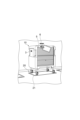
- 2 is a perspective view of the cart of FIG. 1;
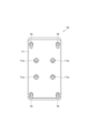
- FIG. 3 is a bottom view of the cart of FIG. 1;
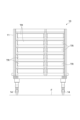
- FIG. 4 is a front view showing an example of the internal structure of the cart of FIG. 1.
- FIG. 5 is a perspective view of the station of FIG. 1;
- FIG. 6 is a perspective view showing the automatic guided vehicle of FIG. 1.
- FIG. 7 is a perspective view showing a state in which the cover of the automatic guided vehicle of FIG. 1 is removed.
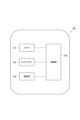
- FIG. 10 is a block diagram showing the configuration of the operating terminal.
- FIG. 11 is a diagram showing an example of a first transmission setting screen displayed on the operating terminal.
- FIG. 12(a) is a perspective view when reading the bar code of the station with the operation terminal.
- FIG. 12(b) is a perspective view when the two-dimensional code of the cart is read by the operation terminal.
- FIG. 13 is a diagram showing an example of a second transmission setting screen displayed on the operating terminal.
- FIG. 14 is a diagram showing an example of a third transmission setting screen displayed on the operating terminal.
- FIG. 15 is a perspective view when reading the two-dimensional code of the destination with the operation terminal.
- FIG. 16 is a diagram showing an example of a fourth transmission setting screen displayed on the operating terminal.
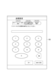
- FIG. 17 is a diagram showing an example of a fifth transmission setting screen displayed on the operating terminal.
- FIG. 18 is a diagram showing an example of a sixth transmission setting screen displayed on the operating terminal.
- FIG. 1 is a schematic configuration diagram showing a transport system 1 according to an embodiment.
- a transportation system 1 is installed indoors, for example, in a hospital, and is a system that realizes automatic transportation of carts (objects to be transported) 10 between a plurality of departments D.
- the transportation system 1 includes a plurality of carts 10 , a plurality of stations 20 , a plurality of automatic guided vehicles 30 , a system controller (controller) 40 , a plurality of access points 50 and a plurality of operation terminals 60 .
- FIG. 2 is a perspective view showing the cart 10 of FIG.
- FIG. 3 is a bottom view of cart 10 of FIG.
- FIG. 4 is a front view showing an example of the internal structure of the cart 10 of FIG.
- the cart 10 is a carriage for storing articles.
- the cart 10 is a cart unit having a rectangular shape in plan view (seen from above). In other words, the cart 10 is a rectangular dedicated cart for loading articles.
- the longitudinal direction of the cart 10 may be simply referred to as the "longitudinal direction”
- the lateral direction of the cart 10 may simply be referred to as the "transverse direction”.
- the cart 10 has a rectangular parallelepiped shape with a width of 800 mm, a length of 900 mm, and a height of 1400 mm.
- the cart 10 can also be used as a hand truck.
- the number of carts 10 used in the transport system 1 is not particularly limited, but may be 100 to 1000, for example.
- Articles stored in the cart 10 include, for example, specimens, injection drugs, sterilized instruments (sterilized containers, collection containers, etc.), medical materials (ME (Medical Engineering) instruments, etc.).
- the cart 10 has a housing 11, a handle 12, a shutter 13 and casters 14.
- the housing 11 has a rectangular box shape.
- An opening 11h is provided on one side of the housing 11 in the lateral direction.
- the inside of the housing 11 is accessible through the opening 11h.
- Inside the housing 11, for example, a plurality of tray receiving hooks for hooking and supporting edges of a tray TR containing articles are provided at appropriate positions.
- a placement plate for placing an article may be provided at an appropriate position inside the housing 11 .
- the bottom surface of the housing 11 is provided with a plurality of recesses 11x with which locate pins 32a (described later) of the automatic guided vehicle 30 are engaged.
- the recesses 11x are arranged on the bottom surface of the housing 11 at four vertex positions (90° rotationally symmetrical positions) of a square formed by sides along the longitudinal direction and the lateral direction.
- the handle 12 is, for example, the part that the user grips.
- the handle 12 is a rod-shaped member that extends vertically.
- the handles 12 are provided at four corners of the housing 11 at positions near the upper center in the vertical direction.
- the shutter 13 is provided so as to be able to close the opening 11h of the housing 11 .
- an up-and-down shutter is used in which a slat, which is formed by connecting elongated plate-like members in a bellows-like manner, is housed in the upper part.
- the shutter 13 is closed by lowering the slat from above, and is opened by lifting the slat from below.
- Casters 14 are provided at the four corners of the bottom surface of housing 11 .
- the caster 14 is configured to rotate 360° around an axis along the vertical direction.
- swivel casters are used, for example.
- FIG. 5 is a perspective view showing station 20 in FIG.
- station 20 is an area where carts 10 are placed.
- the stations 20 are demarcated by position markers 21 on the floor F.
- the station 20 presents a rectangular shape corresponding to the cart 10 in plan view.
- One cart 10 can be placed in the station 20 .
- a plurality of stations 20 are installed, for example, in one department D (see FIG. 1).
- the number of stations 20 installed in the transport system 1 is not particularly limited.
- FIG. 6 is a perspective view showing the automatic guided vehicle 30 of FIG.
- FIG. 7 is a perspective view showing a state in which the cover 31 of the automatic guided vehicle 30 of FIG. 1 is removed.
- FIG. 8 is a block diagram showing the configuration of the automatic guided vehicle 30 of FIG.
- FIG. 9 is a perspective view showing the cart 10 being transported by the automatic guided vehicle 30 of FIG.
- the automatic guided vehicle 30 is a guided vehicle that self-travels on the floor F along a predetermined travel route.
- the automatic guided vehicle 30 automatically conveys the cart 10 between the stations 20 .
- the predetermined travel route is a route set in advance and extends so as to pass between a plurality of departments D.
- the predetermined travel route is set, for example, so as to approach a plurality of stations 20 .
- the automatic guided vehicle 30 adopts a two-wheel speed difference system as a drive mechanism.
- the unmanned guided vehicle 30 is configured to be able to move forward, backward, turn left and right, and spin-turn (turn on the spot).
- the automatic guided vehicle 30 presents a rectangular outer shape in plan view.
- the automatic guided vehicle 30 has a rectangular parallelepiped shape with a width of 500 mm, a length of 700 mm, and a height of 320 mm.
- the number of automatic guided vehicles 30 used in the transport system 1 is not particularly limited, but may be 50, for example.
- the advancing direction of the automatic guided vehicle 30 may be simply referred to as "advancing direction”.
- a direction orthogonal to both the traveling direction and the vertical direction will be described as the “left-right direction”.
- the automatic guided vehicle 30 includes an elevator 32, an electric cylinder 33, a driving wheel 34, a motor 35, a driven wheel 36, a laser range finder 37, a guided vehicle controller 38, and a communication unit 39. have.
- the lift table 32 is a member on which the cart 10 is placed, and is configured to be liftable.
- the lifting platform 32 has a plate-like shape with a thickness extending in the vertical direction.
- the lift platform 32 is provided above the automatic guided vehicle 30 .
- a locating pin 32a is provided on the upper surface of the lifting platform 32 so as to protrude upward.
- the locating pin 32 a is a convex portion that engages with the concave portion 11 x on the bottom surface of the cart 10 placed on the lift table 32 .
- the upper portion of the locate pin 32a is tapered upward.
- the locating pins 32a are arranged on the upper surface of the lift table 32 at four vertex positions (90° rotationally symmetrical positions) of a square formed by sides along the advancing direction and the left-right direction.
- the lifting platform 32 lifts the cart 10 from below when ascending, and lowers the cart 10 to the floor F when descending.
- the electric cylinder 33 is a driving source for raising and lowering the lifting table 32 .
- the electric cylinder 33 is connected to a carrier controller 38 and its operation is controlled by the carrier controller 38 .
- the drive wheels 34 are wheels that drive the automatic guided vehicle 30 .
- a pair of drive wheels 34 are provided at the center of the automatic guided vehicle 30 in the traveling direction and at both ends in the left-right direction.
- a motor 35 is provided for each driving wheel 34 . That is, the pair of motors 35 are connected to the pair of drive wheels 34 respectively, and the pair of motors 35 drive the pair of drive wheels 34 independently.
- the motor 35 is connected to a carrier controller 38 and its operation is controlled by the carrier controller 38 .
- the unmanned guided vehicle 30 can spin-turn by rotating the pair of drive wheels 34 in different directions at a constant speed using the pair of motors 35 .
- the driven wheels 36 are wheels that are not driven and are rotated according to the driving of the drive wheels 34 .
- Two pairs of driven wheels 36 are provided.
- the driving wheels 34 are provided on one side of the automatic guided vehicle 30 in the direction of travel and at both ends in the left and right direction.
- a pair is provided at both ends in the direction.
- the driven wheel 36 is configured, for example, to rotate 360° around an axis extending in the vertical direction.
- the laser range finder 37 is a sensor that detects the surrounding environment of the automatic guided vehicle 30.
- the laser range finders 37 are provided on one side and the other side of the automatic guided vehicle 30 in the traveling direction. A pair of laser range finders 37 cooperate to obtain shape data of 360° around the automatic guided vehicle 30 .
- the laser range finder 37 is not particularly limited, and various sensors can be used as long as they can detect the surrounding environment of the automatic guided vehicle 30 .
- the laser range finder 37 is connected to the carrier controller 38 and outputs the detection result to the carrier controller 38 .
- the guided vehicle controller 38 comprehensively controls the automated guided vehicle 30 .
- the transport vehicle controller 38 is a computer including a CPU (Central Processing Unit), ROM (Read Only Memory), RAM (Random Access Memory), and the like.
- the carrier controller 38 can be configured as software in which, for example, a program stored in a ROM is loaded onto a RAM and executed by a CPU.
- the transport vehicle controller 38 may be configured as hardware such as an electronic circuit.
- the transport vehicle controller 38 may be composed of one device, or may be composed of a plurality of devices. When configured with a plurality of devices, these devices are connected via a communication network such as the Internet or an intranet to logically construct one transport vehicle controller 38 .
- the transport vehicle controller 38 performs travel control and loading/unloading control for transporting the cart 10 from the transport source station 20 to the transport destination station 20 based on the transport command received from the system controller 40 via the communication unit 39.
- SLAM Simultaneous Localization and Mapping
- self-position estimation is performed by comparing the created environment map with the surrounding shape data acquired by the laser range finder 37 .
- travel control the difference in self-position estimation with respect to the recognized self-position is received as a correction value, and travel of the unmanned guided vehicle 30 is controlled along the travel route from the self-position to the target position reflecting the correction value.
- the loading and unloading control loading and unloading of the unmanned guided vehicle 30 are performed by raising and lowering the elevator platform 32 .
- the communication unit 39 is a device that wirelessly communicates with the outside of the automatic guided vehicle 30 .
- the communication unit 39 communicates with the system controller 40 via the access point 50 .
- the communication unit 39 may include, for example, a wireless LAN antenna.
- the electric cylinder 33, the driving wheel 34, the motor 35, the driven wheel 36, the laser range finder 37, the guided vehicle controller 38, and the communication unit 39 are covered and protected by the cover 31 (see FIG. 6). there is
- such an unmanned guided vehicle 30 crawls under the cart 10 (between the cart 10 and the floor F), and raises the lift table 32 in this state to lift the cart 10. It is placed on a table 32 and lifted.
- the automatic guided vehicle 30 travels in a state in which the cart 10 is lifted from below by the lift platform 32 (a state in which the driven wheels 36 are separated from the floor F), thereby conveying the cart 10 .
- the unmanned guided vehicle 30 lowers the lift table 32 on which the cart 10 is placed, thereby bringing the cart 10 into contact with the floor F and unloading the cart 10 from the lift table 32 .
- the system controller 40 comprehensively controls the transport system 1.
- the system controller 40 is a computer comprising a CPU, ROM, RAM, and the like.
- the system controller 40 can be configured, for example, as software in which a program stored in the ROM is loaded onto the RAM and executed by the CPU.
- the system controller 40 may be configured as hardware such as an electronic circuit.
- the system controller 40 may be composed of one device, or may be composed of a plurality of devices. When configured with a plurality of devices, these devices are connected via a communication network such as the Internet or an intranet to logically construct one system controller 40 .
- the system controller 40 generates a transport command for transporting the cart 10 by the unmanned guided vehicle 30 based on an input (transport request) from the host controller (not shown) or the operation terminal 60 .
- the system controller 40 is installed, for example, in a server room.
- the transport command includes a travel route along which the automatic guided vehicle 30 is to travel.
- the transport pattern of the transport command includes normal transport, circular transport, and composite transport.
- Normal transportation is transportation in which the cart 10 is loaded onto the automated guided vehicle 30 at the source station 20 and the cart 10 is unloaded from the automated guided vehicle 30 at the destination station 20 .
- the cyclic transportation is transportation in which the cart 10 is loaded on the unmanned guided vehicle 30 at the station 20 of the transportation source, and after circulating the plurality of stations 20 while the cart 10 is placed thereon, the cart returns to the station 20 of the transportation source.
- round transportation the source of transportation and the destination of transportation are the same.
- the cart 10 is loaded onto an unmanned guided vehicle 30 at the source station 20 in the first section, moved to the second section, and unloaded at the destination station 20 in the second section.
- the cart 10 is loaded onto the automatic guided vehicle 30 at another station 20 in the second department, returned to the first department, and unloaded at the transport destination station 20 in the first department.
- the cart 10 may be unloaded at the transport destination station 20 in a department other than the first and second departments after being loaded onto the automatic guided vehicle 30 in the second department.
- the system controller 40 selects the optimum one from among the multiple automatic guided vehicles 30 using multiple conditions, and assigns a transport command to the selected automatic guided vehicle 30 .
- the plurality of conditions for selecting the automatic guided vehicle 30 are, for example, that the remaining battery level of the automatic guided vehicle 30 is equal to or greater than a predetermined value, that the distance from the transport source station 20 is the closest, and that another cart 10 is currently selected. Includes conditions such as not being transported.
- the access point 50 is a relay device for wireless communication between the system controller 40 and the automatic guided vehicle 30 and wireless communication between the system controller 40 and the operation terminal 60 .
- the access point 50 uses 2.4 GHz or 5 GHz as the frequency band.
- the access point 50 is wired to the system controller 40 via a cable CB.
- the number of access points 50 installed in the transport system 1 is not particularly limited.
- the access point 50 is provided on the ceiling surface or the wall surface.
- the operation terminal 60 is a terminal that receives inputs from the operator.
- Operation terminal 60 includes a touch panel.
- the operation terminal 60 is used to input the cart 10 to be transported, the input of the station 20 of the source of transport, the input of the station 20 of the transport destination, and the like.
- the operation terminal 60 is installed for each department D.
- FIG. A portable terminal such as a tablet terminal is used as the operation terminal 60 .
- One or a plurality of operation terminals 60 are assigned to one department D.
- FIG. Here, one operating terminal 60 is not assigned to a plurality of departments D.
- each of the plurality of carts 10 has a unique two-dimensional code (first ID) 3, as shown in FIGS.
- the two-dimensional code 3 is an identifier for identifying the cart 10 and is a matrix type code readable by the operation terminal 60 .
- the position where the two-dimensional code 3 is provided on the cart 10 is not particularly limited.
- the two-dimensional code 3 is provided on the outer surface (front surface and rear surface) of the housing 11 .
- Each of the plurality of stations 20 has a unique barcode (second ID) 6.
- the barcode 6 is an identifier for identifying the station 20 and is a one-dimensional code readable by the operation terminal 60 .
- the position where the barcode 6 is provided is not particularly limited.
- the bar code 6 is provided on the wall adjacent to the station 20 at a position not hidden by the cart 10 arranged at the station 20 .
- a label 4 is detachably attached to the cart 10 .
- the label 4 displays the transport destination of the cart 10 .
- the name of the destination department D is printed.
- the label 4 includes a two-dimensional code 5 relating to the destination department D.
- the two-dimensional code 5 is an identifier for identifying the destination of the cart 10 and is a matrix type code readable by the operation terminal 60 .
- the position where the label 4 is provided on the cart 10 is not particularly limited.
- the label 4 is provided on the outer surface (upper side surface) of the housing 11 .
- the operation terminal 60 is configured to be able to read the two-dimensional codes 3 and 5 and the barcode 6.
- the operation terminal 60 has a camera 61 , a touch panel (display screen) 62 , a communication section 63 and a control section 64 .
- the camera 61 is imaging equipment for reading (scanning) the two-dimensional codes 3 and 5 and the bar code 6 .
- the touch panel 62 is a device that allows an operator to perform various operations such as touch input and displays various information to the operator.
- the communication unit 63 is a device that communicates with the outside.
- the communication unit 63 communicates with the system controller 40 (see FIG. 1) via the access point 50 (see FIG. 1).
- the control unit 64 is a computer comprising a CPU, ROM, RAM, and the like.
- the control unit 64 can be configured as software in which a program stored in the ROM is loaded onto the RAM and executed by the CPU, for example.
- transmission setting a transmission setting for inputting the transport command
- the control unit 64 uses a pre-stored database or the like.
- the cart 10 corresponding to the two-dimensional code 3 is specified as a transport target. That is, the operating terminal 60 inputs the cart 10 to be transported by reading the two-dimensional code 3 in the transmission settings.
- control unit 64 When the control unit 64 recognizes the barcode 6 from the image captured by the camera 61 in the transmission settings, the control unit 64 refers to the database or the like to specify the station 20 corresponding to the barcode 6 as the transportation source. That is, the operating terminal 60 inputs the transport source station 20 by reading the barcode 6 in the transmission setting.
- the control unit 64 specifies the destination by the input method according to the selection result.
- the method of inputting the destination is "reading input” by the camera 61, "list selection” for selecting from a list of multiple destination candidates, “history input” for selecting from a plurality of destination histories, and "transportation destination”. Includes “ten-key input” that allows the operator to directly enter the number corresponding to .
- control unit 64 When the control unit 64 recognizes the two-dimensional code 5 from the image captured by the camera 61 when "reading input” is selected as the input method for the destination in the transmission settings, the control unit 64 refers to a database or the like. , the department D corresponding to the two-dimensional code 5 is specified as the destination. That is, the operating terminal 60 inputs the transport destination by reading the two-dimensional code 5 in the transmission settings.
- the control unit 64 displays a plurality of destination department D candidates on the touch panel 62 when "list channel selection" is selected as the destination input method in the transmission settings.
- the control unit 64 identifies the selected candidate department D as the transport destination. That is, in the transmission setting, the operation terminal 60 inputs the transport destination by selecting the transport destination candidate. Candidates for a plurality of destination departments D may be stored in advance in the control unit 64 .
- the control unit 64 displays the history of a plurality of destinations (a plurality of departments D that have been destinations in the past) on the touch panel 62 when "history input" is selected as the method of inputting destinations in the transmission settings. .
- the control unit 64 specifies the selected department D as the transport destination. That is, in the transmission setting, the operation terminal 60 inputs the destination by selecting it from the history of the destination.
- the transport destination history may be stored in the control unit 64 .
- the control unit 64 displays buttons 0 to 9 on the touch panel 62 when "numeric key input” is selected as the input method for the destination in the transmission settings.
- the control unit 64 identifies department D corresponding to the directly input number as the destination. That is, in the operation terminal 60, the transport destination is input by directly inputting the number by the operator in the transmission setting. Information about the number of the department D may be stored in the control unit 64 in advance.
- the control unit 64 transmits information about the cart 10, the destination, and the station 20 of the transportation source input (specified) via the touch panel 62 to the system controller 40 via the communication unit 63 as a transportation request. Details of the transmission settings will be described later.
- the operator uses, for example, the operation terminal 60 of the department D of the transportation source, and touches a button (icon) related to transmission settings on the main screen displayed on the touch panel 62 thereof.
- a button icon
- the screen is switched to the transmission setting screen shown in FIG.
- the process is divided in order from step 1 to step 3.
- a first transmission setting screen S1 for selecting the station 20 of the transportation source and the cart 10 of the transportation target is displayed on the touch panel 62 .
- the first transmission setting screen S1 includes a message prompting the operation terminal 60 to read the barcode 6 of the station 20 and the two-dimensional code 3 of the cart 10 .
- the image captured by the camera 61 is displayed on the first transmission setting screen S1.
- the source station 20 is displayed as the originating station, and the destination department D is displayed as the destination department (hereinafter the same).
- the operator uses the camera 61 of the operation terminal 60 to scan the barcode 6 of the station 20 of the transfer source, as shown in FIG. 12(a). read.
- the station 20 of the transfer source is entered, and the number of the station 20 of the transfer source is displayed on the first transmission setting screen S1.
- the operator uses the camera 61 of the operation terminal 60 to display the two-dimensional code 3 of the cart 10 to be transported, as shown in FIG. 12(b). to read.
- the cart 10 to be transported is entered, and the number of the cart 10 to be transported is displayed on the first transmission setting screen S1.
- the operator touches the "next" button on the first transmission setting screen S1, thereby completing the process of step 1.
- the operator can restart the process from the beginning of step 1 by touching the "return to beginning" button (hereinafter the same).
- a second transmission setting screen S2 for selecting the destination department is displayed on the touch panel 62 as a step 2 process.
- the second transmission setting screen S2 is a screen for selecting the input method of the destination.
- the second transmission setting screen S2 includes "reading input” by the camera 61, "list channel selection” for selecting from a list of candidates for a plurality of destinations, "input history” for selecting from a history of a plurality of destinations, and This is an operation screen that allows the operator to select one of the "ten-key input” methods, in which the operator directly inputs the corresponding number, as the method of inputting the destination.
- Reading input is a method of reading the destination department from the code.
- List channel selection is a method of selecting a destination department from a list of departments.
- History input is a method of selecting a destination department from the history.
- Teen-key input is a method of directly inputting the number of the destination department.
- the second transmission setting screen S2 includes a message prompting the user to select the method of inputting the destination. The operator touches one of these items on the second transmission setting screen S2 and touches the button "select destination station” to complete the selection of the input method for the destination.
- the third transmission setting screen S3 includes a message prompting the operation terminal 60 to read the two-dimensional code 5 on the cart 10 .
- the image captured by the camera 61 is displayed on the third transmission setting screen S3.
- the operator reads the two-dimensional code 5 with the camera 61 of the operation terminal 60, as shown in FIG.
- the destination department is entered, and the destination department number and the destination department name are displayed on the third transmission setting screen S3.
- the operator touches the "next" button on the third transmission setting screen S3, thereby completing the process of step 2.
- the fourth transmission setting screen S4 includes a message prompting the user to touch and select a destination department.
- the operator selects one from a list of destination department candidates. As a result, the destination department is entered. Then, the operator touches the "next" button on the fourth transmission setting screen S4, thereby completing the process of step 2.
- the second transmission setting screen S2 when "input history" is selected on the second transmission setting screen S2, transmission to select one from a list of destination departments (history of multiple destinations) in past transportation.
- a setting screen is displayed on the touch panel 62 .
- the operator selects a destination department from the history of transport destinations. As a result, the destination department is entered. Then, the operator touches the "next" button on the transmission setting screen, thereby completing the process of step 2.
- a fifth transmission setting screen S5 for touch-inputting the number of the destination department is displayed on the touch panel 62 as shown in FIG. Is displayed.
- the fifth transmission setting screen S5 includes a message prompting the user to enter the number of the destination department using the numeric keypad. Numeric buttons from 0 to 9 are displayed on the fifth transmission setting screen S5.
- the operator touch-inputs the number of the destination department. As a result, the destination department is entered. Then, the operator touches the "next" button on the fifth transmission setting screen S5, thereby completing the process of step 2.
- a sixth transmission setting screen S6 for confirming the contents (transmission contents) of the transport request to be transmitted is displayed on the touch panel 62.
- the sixth transmission setting screen S6 includes a message prompting confirmation of the transmission content and a message prompting determination if the transmission content is correct.
- the operator confirms the contents of transmission, and if there is no error, touches the "send decision" button on the sixth transmission setting screen S6. Then the process of step 3 is completed. After confirming the transmission contents, if there is an error, the operator can touch the "cancel" button on the sixth transmission setting screen S6 to cancel the transmission contents and restart the process from the beginning of step 1. It is possible.
- the operation terminal 60 transmits to the system controller 40 a transport request to transport the input cart 10 from the input station 20 to the input destination department. Then, the system controller 40 selects and allocates a transport command based on the transport request to an appropriate automatic guided vehicle 30 .
- the unmanned guided vehicle 30 to which the transport command is assigned starts automatic transport according to the transport command.
- the station 20 into which the cart 10 of the destination department is to be carried is automatically selected from a plurality of stations 20 of the destination department based on, for example, the mixed state of the destination departments.
- the cart 10 to be transported can be input by reading the two-dimensional code 3 instead of manual input, and the barcode 6 can be input instead of manual input.
- the station 20 of the transfer source can be input. Therefore, it is possible to reduce the time and effort required for the input and prevent erroneous input. That is, it is possible to easily input the transport command on the operation terminal 60 and prevent erroneous input.
- the operation terminal 60 is configured to be able to read the two-dimensional code 5 of the label 4 associated with the transport destination provided on the cart 10.
- the operation terminal 60 reads the two-dimensional code 5 of the label 4 when performing transmission settings.
- the transport destination can be input by reading the label 4 instead of manual input on the operation terminal 60 . It is possible to more easily perform transmission settings on the operation terminal 60 and to further prevent erroneous input.
- the operation terminal 60 is configured to be able to select one of the transport destination histories, and when inputting a transport command, the transport destination is input by selecting from the transport destination history. be. In this case, it is possible to input the destination department through the operation terminal 60 using the history of the destination department.
- the operation terminal 60 is configured to be able to select one of the candidates for the transport destination, and when inputting a transport command, the transport destination is input by selecting from the candidates for the transport destination. In this case, it is possible to input the destination department through the operation terminal 60 by using the candidates for the destination department.
- the operation terminal 60 is configured so that the number of the destination department can be directly input, and the operator directly inputs the number when inputting a transport command. In this case, it is possible to input the destination department through the operation terminal 60 by using the destination department number directly (manually) input by the operator.
- the object to be transported is the cart 10 .
- the effects described above can be obtained.
- the two-dimensional code 3 of the cart 10 to be transported and the destination department have already been input by a certain operation terminal 60 (first operation terminal) or another operation terminal 60 (second operation terminal). , the transmission settings have already been completed).
- the system controller 40 has transport information in which the two-dimensional code 3 and the destination department are associated.
- the transport information of the system controller 40 is used to display the destination department of the cart 10 on the touch panel 62 of the operation terminal 60.
- the two-dimensional code 3 is used as the first ID in the above embodiment, the first ID is not particularly limited, and various identifiers can be used.
- the barcode 6 is used as the second ID, but the second ID is not particularly limited, and various identifiers can be used.
- the position and size of the provided first ID are not limited, and similarly, the position and size of the provided second ID are not limited.
- the destination department is input by reading the two-dimensional code 5 on the label 4 with the operation terminal 60, but this is not the only option.
- an identifier different from the two-dimensional code 5 may be provided on the label 4 and read by the operation terminal 60 to input the destination department.
- the destination department may be input by reading letters, numbers, or a combination thereof written on the label 4 with the operation terminal 60 .
- the destination department may be input by reading labels (prescriptions, barcodes of electronic paper, etc.) of articles loaded on the cart 10 with the operation terminal 60 .
- the destination department may be input by reading the articles themselves loaded on the cart 10 with the operation terminal 60 .
- the destination department may be input by voice input to the operation terminal 60 .
- the position and size of the label 4 provided are not limited.
- the destination department is input via the operation terminal 60, but when returning the cart 10 to the department to which the cart belongs, for example, the destination department input may be omitted.
- the department to which the cart 10 belongs is set as the destination department D as it is.
- the department to which the cart 10 selected as the transport target belongs is automatically input as the transport destination by manual input or by reading the two-dimensional code 3 (first ID). may be
- the transported object is not particularly limited and may be various objects.
- the transport system 1 is applied to automatically transport carts 10 between a plurality of departments D, but the field to which one aspect of the present invention is applied is not particularly limited, and can be applied to various fields. .
- ⁇ Invention 1> a plurality of transferred objects each having a unique first ID and carrying articles; a plurality of stations each having a unique second ID and placing the transferred object; an automated guided vehicle that transports the object to be transported; an operation terminal that receives input from an operator; a controller that assigns a transport command based on an input received by the operation terminal to the automatic guided vehicle;
- the operation terminal is configured to be able to read the first ID and the second ID,
- the operation terminal is configured to be able to read a label relating to a destination provided on the article or the object to be conveyed, The conveying system according to invention 1, wherein when inputting the conveying command, the conveying destination is input by reading the label.
- the operation terminal is configured to be able to select one of a plurality of transport destination histories or candidates, The transport system according to invention 1, wherein when inputting the transport command, a transport destination is input by selecting from transport destination history or candidates.
- the operation terminal is configured so that the operator can directly enter numbers, letters, or a combination of these relating to the destination,
- the transportation system according to the invention 1 wherein when inputting the transportation command, the transportation destination is input by directly inputting the number, the letter, or a combination thereof by the operator.
- ⁇ Invention 5> When the first ID is read by the first operating terminal which is the operating terminal, the transport destination of the transported object corresponding to the read first ID is already the first operating terminal or the first operating terminal.
- the transportation according to any one of Inventions 2 to 4 wherein information about the transportation destination is displayed on the display screen of the first operation terminal when input is made on a second operation terminal that is another operation terminal.
- ⁇ Invention 6> The conveying system according to any one of inventions 1 to 5, wherein the object to be conveyed is a cart on which articles are loaded.
Landscapes
- Engineering & Computer Science (AREA)
- Aviation & Aerospace Engineering (AREA)
- Radar, Positioning & Navigation (AREA)
- Remote Sensing (AREA)
- Physics & Mathematics (AREA)
- General Physics & Mathematics (AREA)
- Automation & Control Theory (AREA)
- Control Of Position, Course, Altitude, Or Attitude Of Moving Bodies (AREA)
Priority Applications (1)
| Application Number | Priority Date | Filing Date | Title |
|---|---|---|---|
| JP2023562124A JPWO2023089867A1 (https=) | 2021-11-19 | 2022-07-19 |
Applications Claiming Priority (2)
| Application Number | Priority Date | Filing Date | Title |
|---|---|---|---|
| JP2021-188600 | 2021-11-19 | ||
| JP2021188600 | 2021-11-19 |
Publications (1)
| Publication Number | Publication Date |
|---|---|
| WO2023089867A1 true WO2023089867A1 (ja) | 2023-05-25 |
Family
ID=86396584
Family Applications (1)
| Application Number | Title | Priority Date | Filing Date |
|---|---|---|---|
| PCT/JP2022/028117 Ceased WO2023089867A1 (ja) | 2021-11-19 | 2022-07-19 | 搬送システム |
Country Status (3)
| Country | Link |
|---|---|
| JP (1) | JPWO2023089867A1 (https=) |
| TW (1) | TW202328842A (https=) |
| WO (1) | WO2023089867A1 (https=) |
Citations (3)
| Publication number | Priority date | Publication date | Assignee | Title |
|---|---|---|---|---|
| JP2002109410A (ja) * | 2000-10-02 | 2002-04-12 | Nec Corp | 配送手配システム及び方法 |
| JP2017097537A (ja) * | 2015-11-20 | 2017-06-01 | 日本精工株式会社 | 案内用ロボット |
| JP2020187457A (ja) * | 2019-05-13 | 2020-11-19 | 村田機械株式会社 | 院内搬送システム、及び、制御方法 |
-
2022
- 2022-07-19 JP JP2023562124A patent/JPWO2023089867A1/ja active Pending
- 2022-07-19 WO PCT/JP2022/028117 patent/WO2023089867A1/ja not_active Ceased
- 2022-11-17 TW TW111143891A patent/TW202328842A/zh unknown
Patent Citations (3)
| Publication number | Priority date | Publication date | Assignee | Title |
|---|---|---|---|---|
| JP2002109410A (ja) * | 2000-10-02 | 2002-04-12 | Nec Corp | 配送手配システム及び方法 |
| JP2017097537A (ja) * | 2015-11-20 | 2017-06-01 | 日本精工株式会社 | 案内用ロボット |
| JP2020187457A (ja) * | 2019-05-13 | 2020-11-19 | 村田機械株式会社 | 院内搬送システム、及び、制御方法 |
Also Published As
| Publication number | Publication date |
|---|---|
| TW202328842A (zh) | 2023-07-16 |
| JPWO2023089867A1 (https=) | 2023-05-25 |
Similar Documents
| Publication | Publication Date | Title |
|---|---|---|
| US12492074B2 (en) | Hybrid modular storage fetching system | |
| US12509299B2 (en) | Hybrid modular storage fetching system | |
| CN107814126B (zh) | 输送系统以及输送方法 | |
| EP3650376A1 (en) | Relay cargo picking system and picking method | |
| EP4112499B1 (en) | Transport control device, transport control method, and program | |
| WO2018129362A1 (en) | Hybrid modular storage fetching system | |
| JP6556532B2 (ja) | 通信装置、搬送補助具、および搬送システム | |
| JP2021070549A (ja) | ピッキング作業支援装置およびピッキング作業支援プログラム | |
| JP7224453B2 (ja) | ストッカシステム | |
| WO2023089867A1 (ja) | 搬送システム | |
| US12572881B2 (en) | Control device, delivery system, control method, and display plate | |
| JP4817240B2 (ja) | 倉庫管理システム | |
| KR102522451B1 (ko) | 자동화 물류창고시스템 | |
| JP4029659B2 (ja) | 物品保管設備 | |
| JP3443829B2 (ja) | ロケーション管理システムとそれに用いる有人フォークリフト | |
| JP7750050B2 (ja) | 搬送システム | |
| JP7468494B2 (ja) | 搬送システム、無人搬送車、及び無人搬送車の制御方法 | |
| JP2003306213A (ja) | 物品管理設備 | |
| JPH0664647A (ja) | パレット、フォークリフトおよび荷物管理システム | |
| JPH0672441A (ja) | パレット、フォークリフトおよび荷物管理システム | |
| TWI919023B (zh) | 搬運系統、無人搬運車及無人搬運車的控制方法 | |
| JP6273998B2 (ja) | 物品搬送設備 | |
| JP6048206B2 (ja) | 被搬送物の取り扱い方法及び取り扱いシステム | |
| JP4817227B2 (ja) | 入出庫システム | |
| WO2025046838A1 (ja) | 搬送システムおよび搬送方法 |
Legal Events
| Date | Code | Title | Description |
|---|---|---|---|
| 121 | Ep: the epo has been informed by wipo that ep was designated in this application |
Ref document number: 22895156 Country of ref document: EP Kind code of ref document: A1 |
|
| WWE | Wipo information: entry into national phase |
Ref document number: 2023562124 Country of ref document: JP |
|
| NENP | Non-entry into the national phase |
Ref country code: DE |
|
| 122 | Ep: pct application non-entry in european phase |
Ref document number: 22895156 Country of ref document: EP Kind code of ref document: A1 |