WO2023089754A1 - 吸引装置 - Google Patents
吸引装置 Download PDFInfo
- Publication number
- WO2023089754A1 WO2023089754A1 PCT/JP2021/042543 JP2021042543W WO2023089754A1 WO 2023089754 A1 WO2023089754 A1 WO 2023089754A1 JP 2021042543 W JP2021042543 W JP 2021042543W WO 2023089754 A1 WO2023089754 A1 WO 2023089754A1
- Authority
- WO
- WIPO (PCT)
- Prior art keywords
- heating
- suction
- unit
- temperature
- preheating
- Prior art date
- Legal status (The legal status is an assumption and is not a legal conclusion. Google has not performed a legal analysis and makes no representation as to the accuracy of the status listed.)
- Ceased
Links
Images





Classifications
-
- A—HUMAN NECESSITIES
- A24—TOBACCO; CIGARS; CIGARETTES; SIMULATED SMOKING DEVICES; SMOKERS' REQUISITES
- A24F—SMOKERS' REQUISITES; MATCH BOXES; SIMULATED SMOKING DEVICES
- A24F40/00—Electrically operated smoking devices; Component parts thereof; Manufacture thereof; Maintenance or testing thereof; Charging means specially adapted therefor
- A24F40/50—Control or monitoring
- A24F40/57—Temperature control
-
- A—HUMAN NECESSITIES
- A24—TOBACCO; CIGARS; CIGARETTES; SIMULATED SMOKING DEVICES; SMOKERS' REQUISITES
- A24F—SMOKERS' REQUISITES; MATCH BOXES; SIMULATED SMOKING DEVICES
- A24F40/00—Electrically operated smoking devices; Component parts thereof; Manufacture thereof; Maintenance or testing thereof; Charging means specially adapted therefor
- A24F40/10—Devices using liquid inhalable precursors
-
- A—HUMAN NECESSITIES
- A24—TOBACCO; CIGARS; CIGARETTES; SIMULATED SMOKING DEVICES; SMOKERS' REQUISITES
- A24F—SMOKERS' REQUISITES; MATCH BOXES; SIMULATED SMOKING DEVICES
- A24F40/00—Electrically operated smoking devices; Component parts thereof; Manufacture thereof; Maintenance or testing thereof; Charging means specially adapted therefor
- A24F40/40—Constructional details, e.g. connection of cartridges and battery parts
-
- A—HUMAN NECESSITIES
- A24—TOBACCO; CIGARS; CIGARETTES; SIMULATED SMOKING DEVICES; SMOKERS' REQUISITES
- A24F—SMOKERS' REQUISITES; MATCH BOXES; SIMULATED SMOKING DEVICES
- A24F40/00—Electrically operated smoking devices; Component parts thereof; Manufacture thereof; Maintenance or testing thereof; Charging means specially adapted therefor
- A24F40/40—Constructional details, e.g. connection of cartridges and battery parts
- A24F40/46—Shape or structure of electric heating means
-
- A—HUMAN NECESSITIES
- A24—TOBACCO; CIGARS; CIGARETTES; SIMULATED SMOKING DEVICES; SMOKERS' REQUISITES
- A24F—SMOKERS' REQUISITES; MATCH BOXES; SIMULATED SMOKING DEVICES
- A24F40/00—Electrically operated smoking devices; Component parts thereof; Manufacture thereof; Maintenance or testing thereof; Charging means specially adapted therefor
- A24F40/50—Control or monitoring
-
- A—HUMAN NECESSITIES
- A24—TOBACCO; CIGARS; CIGARETTES; SIMULATED SMOKING DEVICES; SMOKERS' REQUISITES
- A24F—SMOKERS' REQUISITES; MATCH BOXES; SIMULATED SMOKING DEVICES
- A24F40/00—Electrically operated smoking devices; Component parts thereof; Manufacture thereof; Maintenance or testing thereof; Charging means specially adapted therefor
- A24F40/50—Control or monitoring
- A24F40/53—Monitoring, e.g. fault detection
-
- A—HUMAN NECESSITIES
- A24—TOBACCO; CIGARS; CIGARETTES; SIMULATED SMOKING DEVICES; SMOKERS' REQUISITES
- A24F—SMOKERS' REQUISITES; MATCH BOXES; SIMULATED SMOKING DEVICES
- A24F40/00—Electrically operated smoking devices; Component parts thereof; Manufacture thereof; Maintenance or testing thereof; Charging means specially adapted therefor
- A24F40/60—Devices with integrated user interfaces
-
- A—HUMAN NECESSITIES
- A24—TOBACCO; CIGARS; CIGARETTES; SIMULATED SMOKING DEVICES; SMOKERS' REQUISITES
- A24F—SMOKERS' REQUISITES; MATCH BOXES; SIMULATED SMOKING DEVICES
- A24F47/00—Smokers' requisites not otherwise provided for
-
- H—ELECTRICITY
- H05—ELECTRIC TECHNIQUES NOT OTHERWISE PROVIDED FOR
- H05B—ELECTRIC HEATING; ELECTRIC LIGHT SOURCES NOT OTHERWISE PROVIDED FOR; CIRCUIT ARRANGEMENTS FOR ELECTRIC LIGHT SOURCES, IN GENERAL
- H05B1/00—Details of electric heating devices
- H05B1/02—Automatic switching arrangements specially adapted to apparatus ; Control of heating devices
- H05B1/0227—Applications
- H05B1/023—Industrial applications
- H05B1/0244—Heating of fluids
Definitions
- the present invention relates to a suction device.
- the device described in Patent Document 1 includes a heater that generates an aerosol by heating an aerosol source, and a heater that heats the aerosol source at a preheating temperature lower than the heating temperature for generating the aerosol. and a controller capable of changing the amount of power to be supplied.
- preheating is performed to heat the aerosol source at a preheating temperature lower than the heating temperature for generating the aerosol when the user is not performing an inhalation operation. If the temperature of the heating unit becomes too high due to this preheating, the amount of the aerosol source to be atomized is greater than the amount of the aerosol source liquid guided to the heating unit. Eventually, there may be no heatable aerosol source even though the user is inhaling. Then, when the heatable aerosol source is exhausted, no aerosol is generated, so the aerosol cannot be inhaled even though the user is inhaling.
- An object of the present invention is to provide an aspiration device capable of suppressing exhaustion of a heatable aerosol source at the time of inhalation.
- the first feature of the present invention completed for this purpose is a liquid storage unit that stores a liquid that generates an aerosol when heated, a heating unit that heats the liquid, and a power supply unit that stores electric power. and a control unit for controlling power supply from the power supply unit to the heating unit, wherein the control unit adjusts the temperature of the liquid so that the liquid vaporizes when a predetermined first condition is satisfied.
- a predetermined first condition is satisfied.
- a suction device that reduces the power consumption in the first heating when shifting to the first heating.
- a second feature is that the control unit sets the upper limit time for continuing the first heating when shifting to the first heating during the second heating, without performing the second heating. may be set to be shorter than the upper limit time for continuing the first heating when shifting to .
- a third feature is that the control unit controls the power supplied during the first heating when shifting to the first heating during the second heating, without performing the second heating. It may be made smaller than the electric power supplied during the first heating when shifting to heating.
- a fourth feature may be that the control section controls the temperature of the heating section so as not to exceed a target temperature.
- a fifth feature may be that the control unit changes the amount of electric power in the first heating according to the amount of the liquid stored in the liquid storage unit.
- a sixth feature may include an operation unit that can be operated by a user, and the second condition may be satisfied when a predetermined operation is performed on the operation unit.
- the power amount in the first heating when shifting to the first heating during the second heating is the power in the first heating when shifting to the first heating without performing the second heating It can be made smaller with greater accuracy than quantity.
- the amount of power in the first heating when shifting to the first heating during the second heating is the power in the first heating when shifting to the first heating without performing the second heating It can be made smaller with greater accuracy than quantity.
- the heating unit is not heated more than necessary, it is possible to highly reliably prevent the heatable aerosol source from running out during suction.
- the fifth feature even if the amount of liquid stored in the liquid storage unit is small, it is possible to highly reliably prevent the exhaustion of the heatable aerosol source during suction.
- the sixth feature since preheating is performed based on the operation of the user who performs the suction operation, it is possible to more accurately suppress the waste of power used for heating.
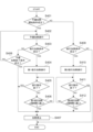
- FIG. 4 is a flowchart showing an example of a procedure of heat treatment performed by a control unit; It is a timing chart for explaining the operation of the suction device.
- (a) is a diagram showing an example of the relationship between the remaining amount and the first suction heating upper limit time.
- (b) is a diagram showing an example of the relationship between the remaining amount and the first suction heating power. It is a figure which shows an example of schematic structure of the sensor part and control part which concern on a modification.
- FIG. 1 is an example of a perspective view showing a schematic configuration of the suction device 1.
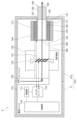
- FIG. 2 is an example of a cross-sectional view showing a schematic configuration of the suction device 1.
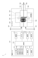
- FIG. 3 is a diagram schematically showing an example of the schematic configuration of the suction device 1.
- a suction device 1 according to the first embodiment is a device that generates a substance to be sucked by a user.
- the substance generated by the suction device 1 is an aerosol.
- the substance produced by the suction device 1 may be a gas.
- the suction device 1 generates an aerosol by heating a liquid aerosol source.
- the suction device 1 includes a power supply unit 110 , a cartridge 120 , a case 10 housing the power supply unit 110 and the cartridge 120 , a mouthpiece 124 , and an end cap 20 housing part of the mouthpiece 124 .
- the power supply unit 110 and the cartridge 120 are configured to be detachable from each other. Aspiration by the user is performed with the cartridge 120 attached to the power supply unit 110 .
- the power supply unit 110 includes a power supply section 111, a sensor section 112, a notification section 113, a storage section 114, a communication section 115, and a control section .
- the power supply unit 110 also has an operation unit 117 that can be operated by a user, and a DC/DC converter 118 .
- the cartridge 120 has a heating portion 121 , a liquid guiding portion 122 and a liquid storing portion 123 .
- An air flow path 180 is formed in the suction device 1 . Each component will be described in order below.
- the power supply unit 111 accumulates power.
- the power supply unit 111 supplies electric power to each component of the suction device 1 .
- the power supply unit 111 may be composed of, for example, a rechargeable battery such as a lithium ion secondary battery.
- the power supply unit 111 may be charged by being connected to an external power supply via a USB (Universal Serial Bus) cable or the like.
- the power supply unit 111 may be charged in a state of being disconnected from the device on the power transmission side by wireless power transmission technology. Alternatively, only the power supply unit 111 may be removed from the suction device 1 or may be replaced with a new power supply unit 111 .
- the sensor unit 112 detects various information regarding the suction device 1 .
- the sensor unit 112 includes a pressure sensor 112p such as a microphone condenser, a flow rate sensor 112q that detects the amount of the aerosol source stored in the liquid storage unit 123, and a temperature sensor 112t that detects the temperature of the heating unit 121. have.
- the sensor unit 112 then outputs the detected information to the control unit 116 .
- the sensor unit 112 outputs information indicating that the user has performed suction to the control unit 116 when the pressure sensor 112p detects a numerical value associated with the user's suction.
- the notification unit 113 notifies the user of information.
- the notification unit 113 is configured by a light-emitting device such as an LED (Light Emitting Diode).
- the notification unit 113 emits light in different light emission patterns when the power supply unit 111 is in a charging required state, when the power supply unit 111 is being charged, when an abnormality occurs in the suction device 1, and the like.
- the light emission pattern here is a concept including color, timing of lighting/lighting out, and the like.
- the notification unit 113 may be configured by a display device that displays an image, a sound output device that outputs sound, a vibration device that vibrates, or the like, together with or instead of the light emitting device.
- the storage unit 114 stores various information for the operation of the suction device 1.
- the storage unit 114 is configured by, for example, a non-volatile storage medium such as flash memory.
- An example of the information stored in the storage unit 114 is information regarding the OS (Operating System) of the suction device 1, such as control details of various components by the control unit 116.
- FIG. Another example of the information stored in the storage unit 114 is information related to suction by the user, such as the number of times of suction, suction time, total suction time, and the like.
- the communication unit 115 is a communication interface for transmitting and receiving information between the suction device 1 and other devices.
- the communication unit 115 performs communication conforming to any wired or wireless communication standard.
- a communication standard for example, wireless LAN (Local Area Network), wired LAN, Wi-Fi (registered trademark), Bluetooth (registered trademark), or the like can be adopted.
- the communication unit 115 transmits information regarding suction by the user to the smartphone in order to display the information regarding suction by the user on the smartphone.
- the communication unit 115 receives new OS information from the server in order to update the OS information stored in the storage unit 114 .
- the control unit 116 functions as an arithmetic processing device and a control device, and controls the general operations within the suction device 1 according to various programs.
- the control unit 116 is realized by an electronic circuit such as a CPU (Central Processing Unit) and a microprocessor.
- the control unit 116 may include a ROM (Read Only Memory) for storing programs to be used, calculation parameters, etc., and a RAM (Random Access Memory) for temporarily storing parameters, etc. that change as appropriate.
- the suction device 1 executes various processes under the control of the controller 116 .
- the operation unit 117 is composed of a button type switch, a touch panel, or the like. Operation unit 117 outputs information operated by the user to control unit 116 . For example, when the power supply unit 110 is powered off and a predetermined activation operation is performed on the operation unit 117 , the operation unit 117 outputs an activation command for the power supply unit 110 to the control unit 116 . The control unit 116 activates the power supply unit 110 upon acquiring the activation command.
- the predetermined activation operation by the operation unit 117 can be exemplified by pressing the operation unit 117 three times in rapid succession.
- the DC/DC converter 118 is connected between the heating unit 121 and the power supply unit 111 when the cartridge 120 is attached to the power supply unit 110 .
- Control unit 116 is connected between DC/DC converter 118 and power supply unit 111 .
- the DC/DC converter 118 is a booster circuit capable of boosting an input voltage, and is configured to be able to supply a voltage obtained by boosting the input voltage or the input voltage to the heating unit 121 .
- the power supplied to the heating unit 121 can be adjusted by the DC/DC converter 118 .
- a switching regulator can be used that converts an input voltage into a desired output voltage by controlling the on/off time of a switching element while monitoring the output voltage. When a switching regulator is used as the DC/DC converter 118, by controlling the switching element, the input voltage can be directly output without being boosted.
- the temperature sensor 112t has a voltage sensor and a current sensor.
- the voltage sensor measures and outputs the voltage value applied to the heating unit 121 .
- the current sensor measures and outputs the current value flowing through the heating unit 121 .
- the output of the voltage sensor and the output of the current sensor are respectively input to control section 116 .
- Control unit 116 acquires the resistance value of heating unit 121 based on the output of the voltage sensor and the output of the current sensor, and acquires the temperature of heating unit 121 according to this resistance value.
- the temperature of the heating section 121 can be considered to be approximately the same as the temperature of the aerosol source heated by the heating section 121 .
- the temperature sensor 112t does not need to have a current sensor if a constant current is applied to the heating unit 121 when the resistance value of the heating unit 121 is obtained. Similarly, if a constant voltage is applied to the heating unit 121 when obtaining the resistance value of the heating unit 121, the temperature sensor 112t may not have a voltage sensor. Also, the temperature sensor 112t may be, for example, a thermistor arranged near the heating unit 121 .
- the liquid reservoir 123 stores an aerosol source.
- the aerosol source is atomized by heating to produce an aerosol.
- Aerosol sources are, for example, polyhydric alcohols such as glycerin and propylene glycol, and liquids such as water.
- the aerosol source may further comprise a tobacco material or an extract derived therefrom that releases flavoring components when heated.
- the aerosol source may further include nicotine. If the inhalation device 1 is a medical inhaler such as a nebulizer, the aerosol source may contain a medicament for inhalation by the patient.
- the liquid guide section 122 guides the aerosol source, which is the liquid stored in the liquid storage section 123, from the liquid storage section 123 and holds it.
- the liquid guiding portion 122 according to the present embodiment is a wick formed by twisting a fibrous material such as glass fiber or a porous material such as porous ceramic. Liquid guide portion 122 is in liquid communication with liquid reservoir portion 123 . Therefore, the aerosol source stored in the liquid storage section 123 spreads over the entire liquid guide section 122 due to the capillary effect.
- the heating unit 121 heats the aerosol source to atomize the aerosol source and generate an aerosol.
- the heating part 121 is made of any material such as metal or polyimide in any shape such as coil, film or blade.
- the heating section 121 is arranged close to the liquid guiding section 122 . In the example shown in FIGS. 2 and 3 , the heating section 121 is composed of a metal coil and wound around the liquid guiding section 122 . Therefore, when the heating part 121 generates heat, the aerosol source held in the liquid guiding part 122 is heated and atomized to generate an aerosol.
- the heating unit 121 generates heat when supplied with power from the power supply unit 111 .
- the air flow path 180 is a flow path for air drawn by the user.
- the air flow path 180 has an air inflow hole 181 that is an inlet of air into the air flow path 180 and an air outflow hole 182 that is an outlet of air from the air flow path 180 at both ends.
- air inlet hole 181 is formed around the operating portion 117 .
- An air outlet hole 182 is formed in the mouthpiece 124 .
- a liquid guide portion 122 is arranged in the middle of the air flow path 180 .
- the aerosol generated by the heating part 121 is mixed with the air introduced from the air inlet 181 .
- the mixed fluid of the aerosol and air is transported to the air outflow hole 182 as indicated by the arrow 190 .
- the case 10 has a cylindrical power unit case 11 that houses the power unit 110 and a cylindrical cartridge case 12 that houses the cartridge 120 .
- the power supply unit case 11 is provided with an operation section 117 that is operable by the user and is exposed from the surface of the power supply unit case 11 .
- the power supply unit case 11 is formed with an air inlet hole 181 for taking in outside air. It can be exemplified that the air inlet hole 181 is formed around the operating portion 117 .
- a pressure sensor 112p is provided near the operation unit 117 .
- the pressure sensor 112p is configured to output the value of the pressure change within the power supply unit 110 caused by the user's suction through the mouthpiece 124 .
- the pressure sensor 112p outputs an output value corresponding to the flow rate of air sucked from the air inlet 181 toward the mouthpiece 124, in other words, the pressure that changes according to the user's suction.
- the end cap 20 has a first cylindrical portion 21 fitted inside an opening of the cartridge case 12 opposite to the power supply unit case 11 , and a second cylindrical portion 21 provided outside the cartridge case 12 . and a cylindrical portion 22 .
- a portion of the first cylindrical portion 21 on the cartridge case 12 side is fitted into the cartridge case 12 and has a flange portion that abuts against the end face of the cartridge case 12 .
- the diameter of the outer peripheral surface of the second cylindrical portion 22 is smaller than the diameter of the outer peripheral surface of the first cylindrical portion 21, and the diameter of the inner peripheral surface is the same as the diameter of the inner peripheral surface of the first cylindrical portion 21. .
- the mouthpiece 124 is a cylindrical member and has a portion on the cartridge case 12 side that is fitted inside the end cap 20 and has a flange that abuts the end face of the end cap 20 .
- the mouthpiece 124 is a member held by the user when inhaling.
- An air outlet hole 182 of an air flow path 180 is formed in the mouthpiece 124 .
- the control unit 116 is activated when the suction device 1 is powered on. For example, the suction device 1 is powered on when the operating portion 117 is quickly pressed three times in succession. Then, when a predetermined condition is established, the control unit 116 supplies power to the heating unit 121 so that the temperature of the liquid aerosol source is equal to or higher than the first temperature at which the aerosol is generated by atomization.
- a predetermined condition can be exemplified by a case where the output value of the pressure sensor 112p of the sensor unit 112 is equal to or greater than a predetermined threshold value.
- a case where the output value of the pressure sensor 112p is equal to or greater than the threshold value is, for example, a case where the user sucks while holding the mouthpiece 124, and the flow rate of the air sucked from the air inlet 181 toward the mouthpiece 124. , the pressure changes and the output value of the pressure sensor 112p exceeds the threshold value.
- the user's sucking while holding the mouthpiece 124 may be referred to as a "sucking operation".
- the first temperature is the boiling point of the aerosol source.
- control unit 116 supplies power to the heating unit 121 to heat the heating unit 121 so that the temperature of the aerosol source is equal to or higher than the boiling point.
- heating the heating unit 121 by supplying power to the heating unit 121 so that the temperature of the aerosol source is equal to or higher than the boiling point may be referred to as “suction heating”.
- Control unit 116 starts suction heating when a predetermined condition is satisfied.
- the predetermined conditions mentioned above may be called “suction heating conditions.”
- the suction heating condition can be exemplified by the fact that the output value of the pressure sensor 112p is greater than or equal to the threshold.
- the control unit 116 controls, for example, the power value supplied to the heating unit 121 to be a predetermined power value for performing suction heating.
- the predetermined power value can be exemplified as a value that is obtained by performing an experiment or the like in advance and stored in the storage unit 114 or the ROM. Further, it is possible to exemplify that the predetermined power value is set so that the temperature of the heating unit 121 during suction heating becomes the suction heating target temperature described later.
- the control unit 116 may set the target temperature of the heating unit 121 during suction heating to be equal to or higher than the first temperature, and control the power supply so that the temperature of the heating unit 121 during suction heating reaches this target temperature. good.
- the target temperature of the heating unit 121 during suction heating may be referred to as "suction heating target temperature”.
- the suction heating target temperature can be exemplified as 180 degrees.
- the control unit 116 supplies electric power to the heating unit 121 via the DC/DC converter 118 so that the temperature of the heating unit 121 detected by the temperature sensor 112t becomes the suction heating target temperature. may be controlled.
- the control unit 116 detects the deviation between the suction heating target temperature stored in the storage unit 114 and the actual temperature of the heating unit 121 detected by the temperature sensor 112t (hereinafter sometimes referred to as “actual temperature”). Based on this, the power supplied to the heating unit 121 may be controlled.
- This temperature control of the heating unit 121 can be realized by, for example, known feedback control.
- the control unit 116 sets a temperature lower than the target suction heating temperature (for example, 175 degrees) (hereinafter referred to as the “set suction heating temperature”). ) and the actual temperature, the power supplied to the heating unit 121 may be controlled.
- the control unit 116 assumes that the suction heating condition is satisfied and performs suction heating. However, when the period during which the output value of the pressure sensor 112p is equal to or greater than the threshold reaches a predetermined upper limit time (for example, 2.4 seconds), the control unit 116 Power supply to the heating unit 121 is stopped.
- a predetermined upper limit time for example, 2.4 seconds
- control unit 116 controls, before the suction heating condition is satisfied, if a predetermined condition different from the suction heating condition (hereinafter sometimes referred to as "preheating start condition") is satisfied. supplies power to the heating unit 121 so that the temperature of the aerosol source is equal to or higher than the second temperature and lower than the first temperature.
- the second temperature can be exemplified as 40 degrees, for example.
- control unit 116 sets the temperature of the aerosol source to the second temperature or higher and lower than the first temperature. Electric power is supplied to the heating unit 121 to heat the heating unit 121 .
- heating the heating unit 121 by supplying power to the heating unit 121 so that the temperature of the aerosol source is equal to or higher than the second temperature and lower than the first temperature may be referred to as “preheating”.
- Control unit 116 starts preheating when a preheating start condition is satisfied.
- the preheating start condition can be exemplified by, for example, being met when a predetermined operation (for example, pressing once) is performed on the operation unit 117 .
- the target of the predetermined operation may be an operation unit different from the operation unit 117 that is the target of the predetermined activation operation to turn on the power supply unit 110 .
- the predetermined operation is not limited to pressing once.
- the control unit 116 controls, for example, the power value supplied to the heating unit 121 to be a predetermined power value for performing preheating.
- the predetermined power value can be exemplified as a value that is obtained by performing an experiment or the like in advance and stored in the storage unit 114 or the ROM. Further, the predetermined power value can be exemplified so that the temperature of the heating unit 121 during preheating becomes a preheating target temperature, which will be described later.
- the control unit 116 sets the target temperature of the heating unit 121 during preheating to a temperature equal to or higher than the second temperature and lower than the boiling point of the aerosol source, and the temperature of the heating unit 121 during preheating reaches this target. Power supply may be controlled so as to achieve the temperature.
- the target temperature of the heating unit 121 during preheating may be referred to as "preheating target temperature”.
- the preheating target temperature can be exemplified as 50 degrees.
- the control unit 116 supplies electric power to the heating unit 121 via the DC/DC converter 118 so that the temperature of the heating unit 121 detected by the temperature sensor 112t becomes the preheating target temperature. may be controlled.
- the control unit 116 controls the power supplied to the heating unit 121 based on the difference between the preheating target temperature stored in the storage unit 114 and the actual temperature of the heating unit 121 detected by the temperature sensor 112t. may be controlled.
- This temperature control of the heating unit 121 can be realized by, for example, known feedback control.
- control unit 116 controls a temperature set to a value (for example, 45 degrees) lower than the preheating target temperature (hereinafter referred to as “preheating set temperature”) so that the actual temperature does not exceed the preheating target temperature. ) and the actual temperature, the power supplied to the heating unit 121 may be controlled.
- the control unit 116 makes the power value for preheating smaller than the power value for suction heating.
- the control unit 116 makes the duty ratio of the PWM signal output to the DC/DC converter 118 smaller when performing preheating than when performing suction heating. For example, a duty ratio of 90% when performing suction heating and a duty ratio of 30% when performing preheating can be exemplified.
- control unit 116 fixes the duty ratio to 30% until the actual temperature reaches the preheating set temperature, and after the actual temperature reaches the preheating set temperature, the actual temperature and the The duty ratio may be changed based on the deviation from the set temperature.
- control unit 116 fixes the duty ratio to 90% until the actual temperature reaches the suction heating set temperature, and after the actual temperature reaches the suction heating set temperature, the actual temperature and the set temperature, the duty ratio may be changed.
- the control unit 116 performs suction heating when the suction heating condition is satisfied during preheating. Therefore, in the suction device 1, the control unit 116 controls power supply to the heating unit 121 as described above to shift to suction heating. In some cases, the process proceeds to suction heating without preheating.
- suction heating when shifting to suction heating after performing preheating is referred to as “first suction heating”
- suction heating when shifting to suction heating without performing preheating is referred to as "second suction heating.”
- heating suction heating when shifting to suction heating without performing preheating.
- control unit 116 sets a predetermined condition for ending preheating (hereinafter referred to as “preheating end condition” in some cases) before the suction heating condition is established. ) is established, the preheating is stopped. This is for suppressing wasteful power consumption associated with preheating.
- a predetermined time for example, 10 seconds
- the suction device 1 configured as described above, in the case of the first suction heating in which preheating is performed before performing the suction heating, suction is performed earlier than in the case of the second suction heating in which preheating is not performed. It is easy to reach the heating target temperature. Therefore, in the case of the first suction heating, the temperature of the aerosol source tends to reach the temperature at which the aerosol is generated by atomization earlier than in the case of the second suction heating. Therefore, in the suction device 1, the amount of aerosol generated at the initial stage of suction by the user is greater when the first suction heating is performed than when the second suction heating is performed. This is for the following reasons.
- the liquid guide section 122 guides and holds the aerosol source, which is the liquid stored in the liquid storage section 123, by a capillary effect, and the heating section 121 is arranged close to the liquid guide section 122 to generate heat.
- An aerosol source is atomized to generate an aerosol. Therefore, as the amount of power supplied to the heating unit 121 increases, the amount of generated aerosol increases.
- the heating unit 121 atomizes the aerosol source guided by the liquid guiding unit 122 by the capillary effect to generate the aerosol
- the phenomenon described below may occur. That is, if the amount of electric power supplied to the heating unit 121 becomes too large, the amount of the aerosol source to be atomized becomes larger than the amount of the aerosol source guided by the liquid guiding unit 122, and finally heating There may be no aerosol source for generating aerosol at section 121 . If the aerosol source does not exist, the heating unit 121 will not generate aerosol, so the user will not be able to inhale the aerosol even if they perform an inhalation operation.
- control unit 116 makes the electric energy (electrical energy) for performing the first suction heating smaller than the electric energy (electrical energy) for performing the second suction heating.
- the amount of the aerosol source to be atomized is suppressed from becoming larger than the amount of the aerosol source guided by the liquid guide section 122. Suppresses depletion of the aerosol source.
- first suction heating power amount The amount of electric power for performing the first suction heating
- second suction heating power amount the amount of electric power for performing the second suction heating
- the control unit 116 adjusts the power supplied to the heating unit 121 when performing the first suction heating (hereinafter sometimes referred to as “first suction heating power”) to the heating unit 121 when performing the second suction heating. (hereinafter sometimes referred to as “second suction heating power”) supplied to the suction heating power (first suction heating power ⁇ second suction heating power).
- control unit 116 sets a predetermined power value as the power value to be supplied to the heating unit 121 when performing the first suction heating as the power value to be supplied to the heating unit 121 when performing the second suction heating. Make it smaller than the specified power value.
- the control unit 116 makes the duty ratio of the PWM signal output to the DC/DC converter 118 when performing the first suction heating smaller than the duty ratio when performing the second suction heating.
- the controller 116 can set the duty ratio when performing the first suction heating to 70% and the duty ratio when performing the second suction heating to 90%. Note that when performing the first suction heating, the control unit 116 fixes the duty ratio to 70% until the actual temperature reaches the set suction heating temperature, and after the actual temperature reaches the set suction heating temperature, The duty ratio may be changed based on the deviation between the actual temperature and the set temperature.
- control unit 116 fixes the duty ratio to 90% until the actual temperature reaches the suction heating set temperature, and after the actual temperature reaches the suction heating set temperature, The duty ratio may be changed based on the deviation between the actual temperature and the set temperature.
- the control unit 116 sets the first suction heating power and the second suction heating power to be the same, and sets the upper limit time for continuing the first suction heating (hereinafter sometimes referred to as “first suction heating upper limit time”). is shorter than the upper limit time for continuing the second suction heating (hereinafter sometimes referred to as “second suction heating upper limit time”) (first suction heating upper limit time ⁇ second suction heating upper limit time). It can be exemplified that the first suction heating upper limit time is 1.7 seconds and the second suction heating upper limit time is 2.4 seconds.
- the control unit 116 may set the first suction heating upper limit time and the second suction heating upper limit time to be the same when making the first suction heating power smaller than the second suction heating power. Alternatively, if the first suction heating power amount is to be less than the second suction heating power amount, control unit 116 sets the first suction heating power to be less than the second suction heating power.
- the upper limit time and the second upper limit time for suction heating may be different, and the first upper limit time for suction heating may be longer or shorter than the second upper limit time for suction heating.
- Control unit 116 sets the first suction heating power to be smaller than the second suction heating power and sets the first suction heating upper limit time to be shorter than the second suction heating upper limit time. amount can be less than the second suction heating power amount.
- FIG. 4 is a flow chart showing an example of the procedure of the heat treatment performed by the control unit 116.
- the control unit 116 repeatedly executes this process, for example, at a predetermined control cycle (for example, every 1 millisecond).
- the control unit 116 determines whether or not the preheating start condition is satisfied (S401). If the preheating start condition is satisfied (YES in S401), control unit 116 performs preheating (S402). After that, the control unit 116 determines whether or not the suction heating condition is satisfied (S403). If the suction heating condition is satisfied (YES in S403), the control unit 116 performs the first suction heating (S404). After that, it is determined whether or not the suction operation has ended (S405).
- the control unit 116 determines whether or not the first suction heating upper limit time has been reached (S406). If the first suction heating upper limit time has not been reached (NO in S406), the control unit 116 performs the processes after S405. When the first suction heating upper limit time is reached (YES in S406) or when the suction operation ends (YES in S405), the control unit 116 stops power supply from the power supply unit 111 to the heating unit 121 to perform heating. is stopped (S407).
- control unit 116 determines whether or not the preheating end condition is satisfied (S408). If the preheating end condition is not satisfied (NO in S408), the control unit 116 performs the processes from S402 onwards. On the other hand, if the preheating end condition is satisfied (YES in S408), control unit 116 stops power supply from power supply unit 111 to heating unit 121 to stop heating (S407).
- the control unit 116 determines whether the suction heating condition is satisfied (S409). If the suction heating condition is not satisfied (NO in S409), the control unit 116 terminates this process. On the other hand, if the suction heating condition is satisfied (YES in S409), the control unit 116 performs the second suction heating (S410). After that, it is determined whether or not the suction operation has ended (S411). When determining that the suction operation has not ended (NO in S411), the control unit 116 determines whether or not the second suction heating upper limit time has been reached (S412).
- the control unit 116 performs the processes from S411 onwards.
- the control unit 116 stops power supply from the power supply unit 111 to the heating unit 121 to perform heating. is stopped (S407).
- FIG. 5 is a timing chart for explaining the operation of the suction device 1.
- FIG. FIG. 5(a) is a timing chart for performing the first suction heating
- FIG. 5(b) is a timing chart for performing the second suction heating.
- FIG. 5(a) at time t1, an operation for turning on the power of the suction device 1 is performed, and at time t2, it is detected that the preheating start condition has been satisfied.
- 3 shows the operation when it is detected that the first suction operation is performed at time t3 (when it is detected that the suction heating condition is satisfied).
- FIG. 5A detects that the first suction operation is no longer performed at time t4, detects that the preheating start condition is satisfied at time t5, and detects that the preheating start condition is satisfied at time t6. It shows the operation when it is detected that the suction operation has been performed for the first time.
- FIG. 5(b) shows a case where an operation for turning on the power of the suction device 1 is performed at time t1, and it is detected that the first suction operation is performed at time t3 thereafter (suction heating conditions are When it is detected that it is established). Further, FIG. 5B shows the operation when it is detected that the first suction operation is not performed at time t4, and that the second suction operation is performed at time t6. ing.
- the timing chart shown in FIG. 5 shows a case where the duty ratio when performing the first suction heating is 70% and the duty ratio when performing the second suction heating is 90%.
- FIG. 5C shows a case where the suction device 1 operates as shown in FIG.
- FIG. 10 is a diagram showing changes in the temperature of the heating unit 121 in a case (hereinafter sometimes referred to as “case 2”).
- the change in temperature in case 1 is indicated by a solid line
- the change in temperature in case 2 is indicated by a dashed line.
- the temperature rise rate of the heating unit 121 after the suction operation is started is larger than in case 1.
- preheating is performed before performing the suction heating, so that the suction heating target temperature is likely to be reached earlier than in the case 2. Therefore, in the case of Case 1, the temperature of the aerosol source tends to reach the temperature at which it atomizes to form an aerosol earlier than in the case of Case 2.
- the amount of aerosol generated at the initial stage of suction by the user is greater when the first suction heating is performed than when the second suction heating is performed.
- the duty ratio when performing the first suction heating is set to 70%, and the duty ratio when performing the second suction heating is set to 90%. Although illustrated, it is not particularly limited to these duty ratios.
- the time from the start of suction heating to reaching the suction heating target temperature is the suction heating when the second suction heating is performed. It is desirable to set both duty ratios so as to be shorter than the time from the start until the suction heating target temperature is reached.
- the suction device 1 includes the liquid storage unit 123 that stores liquid that is an aerosol source that generates an aerosol when heated, the heating unit 121 that heats the liquid, and the power supply unit 111 that stores electric power. and a control unit 116 that controls power supply from the power supply unit 111 to the heating unit 121 . Then, when a suction heating condition, which is an example of a predetermined first condition, is established, the control unit 116 sets the temperature of the liquid that is the aerosol source to a first temperature (for example, boiling point) at which the liquid vaporizes or higher. Suction heating is performed as an example of the first heating.
- a suction heating condition which is an example of a predetermined first condition
- control unit 116 sets the temperature of the liquid, which is the aerosol source, to a second temperature (for example, 40 degrees) or higher and lower than the first temperature (eg, boiling point). Then, the control unit 116 makes the amount of power in the first suction heating that transitioned to suction heating during preheating smaller than the amount of power in the second suction heating that transitioned to suction heating without preheating.
- a second temperature for example, 40 degrees
- the first temperature eg, boiling point
- the suction device 1 performs preheating when the preheating start condition is satisfied before the suction heating condition is satisfied, and then performs suction heating when the suction heating condition is satisfied.
- the suction device 1 configured in this way, by performing suction heating after performing preheating, the amount of aerosol at the initial stage of suction becomes larger than when suction heating is performed without preheating.
- the second temperature has been exemplified as 40 degrees, it is not particularly limited to 40 degrees.
- the purpose of the preheating is to raise the temperature of the aerosol source liquid in advance before performing suction heating, so the second temperature should be higher than the temperature of the location where the suction device 1 is used. For example, if the area where the suction device 1 is used is Japan, the second temperature should be higher than the air temperature in Japan. Since the temperature changes according to the season, the second temperature may be changed according to the season.
- the preheating target temperature is illustrated as being 50 degrees, it is not particularly limited to 50 degrees. The preheating target temperature may be changed in the same manner as the second temperature, such as by setting the second temperature +10 degrees.
- the predetermined power value may be changed in the same manner as the change in the second temperature. good. That is, the predetermined power value and preheating target temperature may be changed according to the region or season where the suction device 1 is used.
- the amount of electric power in the first suction heating is smaller than the amount of electric power in the second suction heating. Also, the larger amount of the aerosol source to be atomized is suppressed. As a result, according to the suction device 1, even if preheating is performed, the absence of an aerosol source capable of being heated by the heating unit 121, which is necessary for generating an aerosol during suction, is suppressed.
- control unit 116 sets the upper limit time for continuing the first suction heating to be shorter than the upper limit time for continuing the second suction heating (first upper limit time for suction heating ⁇ second upper limit time for suction heating).
- first upper limit time for suction heating is more accurately reduced than the amount of electric power in the second suction heating, so there is an aerosol source that can be heated by the heating unit 121, which is necessary to generate an aerosol during suction. It is suppressed with high certainty.
- control unit 116 makes the power supplied during the first suction heating smaller than the power supplied during the second suction heating (first suction heating power ⁇ second suction heating power).
- first suction heating power ⁇ second suction heating power the amount of electric power in the first suction heating is more accurately reduced than the amount of electric power in the second suction heating, so there is an aerosol source that can be heated by the heating unit 121, which is necessary to generate an aerosol during suction. It is suppressed with high certainty.
- control unit 116 sets the upper limit time for continuing the first suction heating to be shorter than the upper limit time for continuing the second suction heating (first upper limit time for suction heating ⁇ second upper limit time for suction heating).
- the power supplied during suction heating is made smaller than the power supplied during second suction heating (first suction heating power ⁇ second suction heating power). This more reliably suppresses the absence of an aerosol source capable of being heated by the heating unit 121, which is necessary for generating an aerosol during inhalation.
- control unit 116 controls the temperature of the heating unit 121 so as not to exceed the target temperature. As a result, it is possible to suppress the temperature of the heating unit 121 from increasing more than necessary. The non-existence of the source is suppressed with a high degree of certainty.
- the suction device 1 includes a flow rate sensor 112q as an example of a detection unit that detects the amount of liquid stored in the liquid storage unit 123 (hereinafter sometimes referred to as “remaining amount”). changes the amount of electric power for suction heating according to the amount (remaining amount) of liquid detected by the flow sensor 112q.
- the control unit 116 changes at least one of the first suction heating upper limit time and the first suction heating power according to the remaining amount.
- FIG. 6A is a diagram showing an example of the relationship between the remaining amount and the first suction heating upper limit time.
- the controller 116 sets the first suction heating upper limit time to the predetermined time.
- the predetermined time can be exemplified as 1.7 seconds.
- the predetermined amount can be exemplified as 30% of the maximum amount when the remaining amount is the same as the maximum amount that can be stored in the liquid storage unit 123 as 100%.
- the control unit 116 gradually shortens the first suction heating upper limit time from the predetermined time as the remaining amount decreases. do.
- the lack of an aerosol source capable of being heated by the heating unit 121 which is necessary for generating an aerosol during inhalation, is highly reliably suppressed.
- FIG. 6B is a diagram showing an example of the relationship between the remaining amount and the first suction heating power.
- the control unit 116 sets the first suction heating power to the predetermined power when performing the first suction heating.
- the predetermined power can be exemplified as 4W.
- the control unit 116 increases the first suction heating power when performing the first suction heating as the remaining amount decreases. The power is gradually reduced from the predetermined power.
- the preheating target temperature can be sufficiently reached when the suction operation is performed. From the above, it is desirable to start preheating before the minimum heating time during which the suction operation can be performed with high accuracy.
- the suction device 1 has been moved to the mouth. This is because the user moves the suction device 1 to the mouth before performing the suction operation. In particular, it is considered that the suction device 1 is moved to the mouth during the first suction operation.
- the suction device 1 is located near the mouth. This is because the suction device 1 is near the mouth when the user performs a suction operation. In particular, before the second and subsequent suction operations, it is considered that the suction device 1 is kept near the mouth continuously after the previous suction operation.
- the suction device 1 touches the lips. This is because the user holds the mouthpiece 124 when performing a suction operation. Therefore, the above (1) to (3) may be used as the conditions for starting preheating, and the satisfaction of the conditions for starting preheating may be detected as described below.
- FIG. 7 is a diagram showing an example of schematic configurations of the sensor unit 112 and the control unit 116 according to the modification.
- the control unit 116 can be exemplified by detecting that the preheating start condition is satisfied as follows. It is conceivable that the user picks up and lifts the suction device 1 placed on a desk or table, for example, before performing the suction operation. Therefore, the sensor unit 112 has a gyro sensor 112j, and the control unit 116 detects that the preheating start condition is Detecting that it has been established can be exemplified. It can be exemplified that the gyro sensor 112 j is provided inside the power supply unit case 11 .
- the control unit 116 determines that the output value of the gyro sensor 112j is closer to the altitude of the mouthpiece 124 than the altitude of the power supply unit 111, based on the value indicating that the altitude of the power supply unit 111 and the altitude of the mouthpiece 124 are the same.
- the state in which the power supply unit 111 and the mouthpiece 124 are at the same altitude is not limited to the case where the power supply unit 111 and the mouthpiece 124 are at the same altitude. may be 1 cm or less. This is because, when the height difference between the power supply unit 111 and the mouthpiece 124 is 1 cm or less, it can be considered that the suction device 1 is oriented sideways.
- the sensor unit 112 since the user touches the suction device 1 with a hand before performing a suction operation, the sensor unit 112 has a tactile sensor 112s, and the control unit 116 controls the output value of the tactile sensor 112s so that the hand touches the suction device 1. It may be detected that the preheating start condition is satisfied when the touch is indicated. Note that the tactile sensor 112s may be attached to the power supply unit case 11 while being exposed from the surface of the power supply unit case 11 that houses the power supply unit 110, for example.
- the sensor unit 112 has an acceleration sensor 112a, and the control unit 116 detects that the preheating start condition is satisfied when the output value of the acceleration sensor 112a exceeds a predetermined threshold value. good.
- a downward inertial force acts, and the acceleration sensor 112a indicates positive acceleration.
- An upward inertial force acts, and the acceleration sensor 112a indicates negative acceleration.
- the acceleration sensor 112a can be exemplified by being provided inside the power supply unit case 11 .
- the sensor unit 112 has an altitude sensor 112h, and the control unit 116 detects that the preheating start condition is satisfied when the amount of change in the output value of the altitude sensor 112h exceeds a predetermined threshold value. It can be detected.
- the altitude sensor 112 h can be exemplified by being provided inside the power supply unit case 11 .
- control unit 116 controls the suction device 1 to move from the vicinity of the waist to the mouth when the amount of change in the output value of the pressure sensor 112p exceeds a predetermined threshold value. It may be detected that the preheating start condition is satisfied by estimating that it has been moved.
- the suction device 1 has a LiDAR (Light Detection and Ranging) 112l that measures the distance between the suction device 1 and the mouth, and the control unit 116 controls the output value of the LiDAR 112l to measure the distance between the suction device 1 and the mouth. It may be detected that the condition for starting preheating is established when the distance of has become equal to or less than a predetermined threshold value.
- the LiDAR 112l normally measures the distance to the lower lip because it is moved upward from the position below the mouth to the mouth.
- the unit 116 detects that the preheating start condition is satisfied when the distance measured by the LiDAR 112l becomes equal to or less than a predetermined threshold.
- the control unit 116 compares the distance measured by the LiDAR 112l with the portion of contact between the upper and lower lips stored in the storage unit 114 or ROM in advance and the nose. Estimate the distance between the part where the upper lip and the lower lip contact and the suction device 1 using the distance, and the preheating start condition is established when the estimated distance is equal to or less than a predetermined threshold. You can detect what you have done.
- the LiDAR 112l can be exemplified by being attached to the end cap 20, for example. Alternatively, LiDAR 112 l may be attached to mouthpiece 124 .
- the infrared sensor 112i can measure the user's body temperature. It may be detected that the preheating start condition is met when the value becomes equal to or greater than a predetermined threshold value.
- the infrared sensor 112i can be exemplified by being attached to the end cap 20, for example. Alternatively, infrared sensor 112i may be attached to mouthpiece 124 .
- the suction device 1 has a camera 112c, and the control unit 116 detects that the preheating start condition is satisfied when the camera 112c captures an image of the suction device 1 approaching the mouth of the user. good.
- the image captured by the camera 112c may be a still image or a moving image. In the case of a still image, the camera 112c should take an image, for example, every 1 millisecond.
- the camera 112c can be exemplified by being attached to the end cap 20, for example. Alternatively, camera 112 c may be attached to mouthpiece 124 .
- the control unit 116 can detect that the preheating start condition is satisfied as follows.
- the odor sensor 112n can measure volatile sulfur compounds generated in the user's mouth.
- the output value of the sensor 112n is equal to or greater than a predetermined threshold value, it may be detected that the preheating start condition is established.
- the odor sensor 112n a sensor capable of measuring the flavor component contained in the aerosol that can be inhaled by the suction device 1 is used, and the control unit 116 detects when the output value of the odor sensor 112n is equal to or greater than a predetermined threshold value.
- it may be detected that the preheating start condition is established.
- the control unit 116 may detect that the preheating start condition is met when the output value of the humidity sensor 112k becomes equal to or greater than a predetermined threshold value.
- the control unit 116 may detect that the preheating start condition is met when the output value of the CO 2 sensor 112o is equal to or greater than a predetermined threshold value.
- the odor sensor 112n, the humidity sensor 112k, and the CO2 sensor 112o can be exemplified by being attached to the end cap 20, for example.
- the odor sensor 112n, the humidity sensor 112k, and the CO2 sensor 112o may be attached to the mouthpiece 124.
- the control unit 116 determines that the suction device 1 is near the mouth when the output value of the infrared sensor 112i is equal to or greater than a predetermined threshold value. , it may be detected that the preheating start condition is met. Further, when the output value of the LiDAR 112l indicates that the distance between the suction device 1 and the mouth is equal to or less than a predetermined threshold value, the control unit 116 detects that the preheating start condition is satisfied. can be Further, the control unit 116 may detect that the preheating start condition is met when the camera 112c captures an image that the suction device 1 is near the user's mouth.
- the tactile sensor 112m is attached while being exposed from the surface of the mouthpiece 124, and the control unit 116 detects that the output value of the tactile sensor 112m indicates that the mouth is touching the mouthpiece 124. It can be exemplified to detect that the preheating start condition is satisfied when the condition is indicated.
- the suction device 1 includes the above-described gyro sensor 112j, tactile sensor 112s, acceleration sensor 112a, altitude sensor 112h, LiDAR 112l, infrared sensor 112i, camera 112c, odor sensor 112n, tactile sensor 112m, humidity sensor 112k, and CO At least two or more of the two sensors 112o may be provided, and the control section 116 may detect that the preheating start condition is established based on the output values from the two or more sensors. For example, during the first suction operation, the control unit 116 determines that the output value of the gyro sensor 112j indicates that the suction device 1 is oriented vertically, and that the suction device 1 has moved from bottom to top.
- the controller 116 determines that the output value of the gyro sensor 112j indicates that the suction device 1 is oriented vertically, and that the output value of the infrared sensor 112i is predetermined. It may be detected that the preheating start condition is met when the preheating start condition is equal to or greater than the set threshold. This makes it possible to more accurately detect that the preheating start condition has been established.
- the suction device 1 includes the above-described gyro sensor 112j, tactile sensor 112s, acceleration sensor 112a, altitude sensor 112h, LiDAR 112l, infrared sensor 112i, camera 112c, odor sensor 112n, tactile sensor 112m, humidity sensor 112k, and CO
- the control section 116 may detect that the preheating start condition is established based on the output values from the three or more sensors. For example, during the first suction operation, the control unit 116 determines that the output value of the gyro sensor 112j indicates that the suction device 1 is oriented vertically, and that the suction device 1 has moved from bottom to top.
- the controller 116 determines that the output value of the gyro sensor 112j indicates that the suction device 1 is oriented vertically, and that the output value of the infrared sensor 112i is predetermined. It may be detected that the preheating start condition is satisfied when the output value of the odor sensor 112n is equal to or higher than a predetermined threshold and the output value of the odor sensor 112n is equal to or higher than a predetermined threshold. This makes it possible to more accurately detect that the preheating start condition has been established.
- the suction device 1 learns the time interval between successive suction operations, and the control unit 116 calculates the minimum heating time for the expected start of the (n+1)-th suction operation after the n-th suction operation.
- the preheating start condition may be satisfied when the time has come.
- the control unit 116 calculates the average value of the time intervals between successive suction operations, and stores this average value in the storage unit 114 as the average time interval. Then, the control unit 116 may determine that the preheating start condition is met when (average time interval ⁇ minimum heating time) has elapsed after the n-th suction operation. For example, if the average time interval is 15 seconds and the minimum heating time is 2 seconds, the control unit 116 regards the elapse of 13 seconds after the n-th suction operation as the preheating start condition being met. It can be detected.
- control unit 116 stops preheating when the preheating end condition is satisfied after performing preheating. For example, control unit 116 stops preheating when a predetermined time (for example, 10 seconds) has elapsed after starting preheating. Therefore, compared to a configuration in which preheating is continued until the suction operation is performed after preheating is started, the period for performing preheating can be shortened, so power consumption for preheating can be suppressed. can.
- a predetermined time for example, 10 seconds
- the preheating end condition may be the following condition other than the elapse of a predetermined time (for example, 10 seconds) after the preheating is started as described above.
- the control unit 116 sets the preheating end condition to that the output value of the gyro sensor 112j indicates that the orientation of the suction device 1 has been changed from vertical to horizontal.
- the control unit 116 determines that the altitude of the power supply unit 111 and the altitude of the mouthpiece 124 are the same, based on the value indicating that the altitude of the mouthpiece 124 is higher than the altitude of the power supply unit 111, based on the output value of the gyro sensor 112j.
- a change to a value indicating a state is set as the preheating end condition. This is because, if the suction device 1 is placed on, for example, a desk or a table, it is considered unlikely that the suction operation will be performed within the minimum heating time.
- control unit 116 may set the fact that the output value of the tactile sensor 112s no longer indicates that the hand is touching the suction device 1 as the preheating end condition. This is because it is considered unlikely that the suction operation will be performed within the minimum heating time when the user releases the suction device 1 .
- control unit 116 determines that the output value of the acceleration sensor 112a, which becomes negative acceleration when the suction device 1 is moved from top to bottom, has become equal to or less than a predetermined negative threshold. It can be used as a condition. This is because, for example, when the user moves the suction device 1 from the mouth to the vicinity of the waist, it is considered unlikely that the suction operation will be performed within the minimum heating time.
- the control unit 116 sets the amount of change in the output value of the altitude sensor 112h to a predetermined value.
- the preheating end condition may be set to be equal to or less than a negative threshold. This is because, for example, when the user moves the suction device 1 from the mouth to the vicinity of the waist, it is considered unlikely that the suction operation will be performed within the minimum heating time.
- control unit 116 controls the suction device 1 to move from the mouth to the vicinity of the waist when the amount of change in the output value of the pressure sensor 112p is equal to or less than a predetermined negative threshold value. It may be assumed that the preheating end condition is established by estimating that the robot has been moved to .
- the control unit 116 may set the following items as the preheating end condition. .
- the preheating end condition may be satisfied when the distance from the user's mouth exceeds a predetermined threshold.
- the control unit 116 may set the preheating termination condition that the output value of the LiDAR 112l indicates that the distance between the suction device 1 and the mouth exceeds a predetermined threshold.
- the control unit 116 may set the fact that the output value of the infrared sensor 112i is less than a predetermined threshold value as the preheating end condition.
- control unit 116 may set the fact that the camera 112c has imaged that the suction device 1 is not near the user's mouth as the preheating end condition. Further, the control unit 116 may set the condition that the output value of the odor sensor 112n is less than a predetermined threshold value as the preheating end condition. Further, the control unit 116 may set the condition that the output value of the humidity sensor 112k is less than a predetermined threshold value as the preheating end condition. Further, the control unit 116 may set the condition that the output value of the CO 2 sensor 112o is less than a predetermined threshold value as the preheating termination condition.
- the suction device 1 includes the above-described gyro sensor 112j, tactile sensor 112s, acceleration sensor 112a, altitude sensor 112h, LiDAR 112l, infrared sensor 112i, camera 112c, odor sensor 112n, tactile sensor 112m, humidity sensor 112k, and CO At least two or more of the two sensors 112o may be provided, and the control section 116 may determine whether or not the preheating end condition is satisfied based on the output values from the two or more sensors.
- the controller 116 determines that the output value of the acceleration sensor 112a indicates that the suction device 1 has moved from top to bottom, and that the output value of the gyro sensor 112j indicates that the suction device 1 is oriented sideways. In this case, it may be determined that the preheating end condition is met. Further, the control unit 116 controls the preheating when the output value of the acceleration sensor 112a indicates that the suction device 1 has moved from top to bottom and the output value of the infrared sensor 112i is less than a predetermined threshold. It may be determined that the end condition is satisfied. This makes it possible to more accurately determine that the suction operation is not performed within the minimum heating time.
- control unit 116 can determine with high accuracy that the possibility of the suction operation being performed within the minimum heating time is low and stop the preheating. Wasteful power consumption associated with heating can be suppressed.
- the timing of starting preheating should be the event that is expected to satisfy the suction heating condition. is not limited to the case of detecting
- the control unit 116 may start preheating when the suction device 1 is powered on and started, and then stop preheating when the preheating end condition is satisfied. Further, the control unit 116 may change from suction heating to preheating at the timing when the n-th suction operation is finished, and then stop preheating when the preheating end condition is satisfied.
- FIG. 8 is a diagram schematically showing an example of the schematic configuration of the suction device 2 according to the second embodiment.
- a suction device 2 according to the second embodiment differs from the suction device 1 according to the first embodiment in that a flavor imparting cartridge 130 is provided. Further, the suction device 2 differs from the suction device 1 in that it has a case 210 instead of the case 10 . Differences from the first embodiment will be described below. The same reference numerals are used for the same items in the first embodiment and the second embodiment, and detailed descriptions thereof are omitted.
- the flavoring cartridge 130 has a flavor source 131 .
- Flavor source 131 is a component for imparting flavor components to the aerosol.
- the flavor source 131 may be derived from tobacco, such as a processed product obtained by molding shredded tobacco or tobacco raw materials into granules, sheets, or powder. Flavor sources 131 may also include non-tobacco sources made from plants other than tobacco (eg, mints and herbs). As an example, flavor source 131 may include a flavoring ingredient such as menthol. Note that the flavor source 131 may be placed inside a container such as a capsule.
- the flavor source 131 is arranged downstream of the liquid guide section 122 (closer to the air outflow hole 182).
- the aerosol generated by the heating part 121 is mixed with the air introduced from the air inlet 181 .
- the mixed fluid of aerosol and air passes through flavor source 131 and is transported to air outflow hole 182 as indicated by arrow 192 .
- the flavor component contained in the flavor source 131 is added to the aerosol.
- the case 210 has a cylindrical flavor imparting cartridge case 13 that accommodates the flavor imparting cartridge 130 in addition to the power supply unit case 11 and the cartridge case 12 .
- the flavor imparting cartridge 130 and the cartridge 120 are configured to be detachable from each other.
- An end cap 20 is attached to the opening of the flavor imparting cartridge case 13 on the side opposite to the cartridge case 12 .
- the suction by the user is performed with the cartridge 120, the flavor imparting cartridge 130, and the power supply unit 110 attached to each other, the end cap 20 attached to the flavor imparting cartridge case 13, and the mouthpiece 124 attached to the end cap 20. , is done.
- control unit 116 performs preheating in advance by performing suction heating in the same manner as described in the first embodiment. Even so, it is possible to prevent the absence of an aerosol source capable of being heated by the heating unit 121, which is necessary for generating an aerosol during inhalation.
- FIG. 9 is a diagram schematically showing an example of the schematic configuration of the suction device 3 according to the third embodiment.
- a suction device 3 according to the third embodiment differs from the suction device 1 according to the first embodiment in that a susceptor 161 and an electromagnetic induction source 162 are provided instead of the heating unit 121 . Differences from the first embodiment will be described below. The same reference numerals are used for the same items in the first embodiment and the third embodiment, and detailed description thereof will be omitted.
- the susceptor 161 generates heat by electromagnetic induction.
- the susceptor 161 is made of a conductive material such as metal.
- the susceptor 161 is arranged close to the liquid guide portion 122 .
- the susceptor 161 is composed of a metal lead wire and wound around the liquid guide portion 122 .
- the electromagnetic induction source 162 causes the susceptor 161 to generate heat by electromagnetic induction.
- the electromagnetic induction source 162 is composed of, for example, a coiled wire.
- the electromagnetic induction source 162 generates a magnetic field when alternating current is supplied from the power supply section 111 .
- the electromagnetic induction source 162 is arranged at a position where the susceptor 161 overlaps the generated magnetic field. Therefore, when a magnetic field is generated, an eddy current is generated in the susceptor 161 and Joule heat is generated. Then, the Joule heat heat heats the aerosol source held in the liquid guide section 122 and atomizes it to generate an aerosol.
- the control unit 116 controls power supply to the electromagnetic induction source 162 in the same manner as the control unit 116 controls power supply to the heating unit 121 according to the first embodiment. Power supply control is performed, and heat treatment of the susceptor 161 is performed. Then, in the heat treatment of the susceptor 161, the control unit 116 performs suction heating in the same manner as described in the first embodiment, so that even if preliminary heating is performed in advance, aerosol is generated at the time of suction. It is possible to suppress the absence of an aerosol source capable of being heated by the heating unit 121, which is necessary for the above.
- FIG. 10 is a diagram schematically showing an example of the configuration of the suction device 4 according to the fourth embodiment.
- the suction device 4 according to the fourth embodiment heats an aerosol source as a liquid and heats a base material including the aerosol source to generate an aerosol.
- the point of generation is different.
- the suction device 4 differs from the suction device 1 in that it has a case 410 instead of the case 10 . Differences from the first embodiment will be described below.
- the same reference numerals are used for the same items in the first embodiment and the fourth embodiment, and detailed description thereof will be omitted.
- the suction device 4 includes a power supply unit 110, a heating section 121, a liquid guide section 122, a liquid storage section 123, a substrate heating section 171, a holding section 140, and a heat insulating section. 144. Then, in the suction device 4 , the user performs suction while the stick-shaped base material 150 is held by the holding portion 140 .
- the holding part 140 has an internal space 141 and holds the stick-shaped base material 150 while accommodating a part of the stick-shaped base material 150 in the internal space 141 .
- the holding part 140 has an opening 142 that communicates the internal space 141 with the outside, and holds the stick-shaped substrate 150 inserted into the internal space 141 through the opening 142 .
- the holding portion 140 is a cylindrical body having an opening 142 and a bottom portion 143 as a bottom surface, and defines a columnar internal space 141 .
- the holding part 140 is configured such that the inner diameter is smaller than the outer diameter of the stick-shaped base material 150 at least in part in the height direction of the cylindrical body, and holds the stick-shaped base material 150 inserted into the internal space 141.
- the stick-shaped substrate 150 can be held by pressing from the outer periphery.
- the retainer 140 also functions to define air flow paths through the stick-shaped substrate 150 .
- An air inlet hole which is an inlet for air into the flow path, is arranged, for example, in the bottom portion 143 .
- the air outflow hole which is the exit of air from such a channel, is the opening 142 .
- the stick-shaped base material 150 is a stick-shaped member.
- the stick-type substrate 150 has a substrate portion 151 and a mouthpiece portion 152 .
- Substrate portion 151 includes an aerosol source.
- the aerosol source is atomized by heating to produce an aerosol.
- the aerosol source may be tobacco-derived, such as, for example, processed pieces of cut tobacco or tobacco material formed into granules, sheets, or powder. Aerosol sources may also include non-tobacco sources made from plants other than tobacco, such as mints and herbs. By way of example, the aerosol source may contain perfume ingredients such as menthol. If the inhalation device 4 is a medical inhaler, the aerosol source may contain a medicament for inhalation by the patient.
- the aerosol source is not limited to solids, and may be, for example, polyhydric alcohols such as glycerin and propylene glycol, and liquids such as water. At least a portion of the base material portion 151 is accommodated in the internal space 141 of the holding portion 140 while the stick-shaped base material 150 is held by the holding portion 140 .
- the mouthpiece part 152 is a part that is held by the user when inhaling. At least part of the mouthpiece 152 protrudes from the opening 142 when the stick-shaped base material 150 is held by the holding part 140 .
- air flows into the holder 140 through the air inlet 187 .
- the air that has flowed in passes through the internal space 141 of the holding part 140 , that is, passes through the base material part 151 and reaches the inside of the user's mouth together with the aerosol generated from the base material part 151 .
- the base material heating unit 171 heats the base material unit 151 to atomize the aerosol source and generate aerosol.
- the substrate heating part 171 is made of any material such as metal or polyimide.
- the substrate heating part 171 is configured in a film shape and arranged so as to cover the outer periphery of the holding part 140 . Then, when the substrate heating part 171 generates heat, the aerosol source contained in the stick-shaped substrate 150 is heated from the outer periphery of the stick-shaped substrate 150 and atomized to generate an aerosol.
- the substrate heating unit 171 generates heat when supplied with power from the power supply unit 111 .
- the air outlet hole 188 of the air flow path 186 is arranged in the bottom part 143 of the holding part 140 .
- the internal space 141 of the holding portion 140 and the air flow path 186 communicate with each other through the air outlet hole 188 .
- the air flow path 186 is a flow path of air sucked by the user.
- the air flow path 186 has a tubular structure having an air inflow hole 187 that is an inlet of air into the air flow path 186 and an air outflow hole 188 that is an outlet of air from the air flow path 186 at both ends.
- air inlet hole 187 is arranged at an arbitrary position of the suction device 4 .
- the air outflow holes 188 are arranged in the bottom 143 of the holding part 140 .
- a liquid guide portion 122 is arranged in the middle of the air flow path 186 .
- the aerosol generated by the heating part 121 is mixed with the air that has flowed through the air inlet 187 .
- the mixed fluid of aerosol and air is transported to the internal space 141 of the holding section 140 via the air outflow holes 188 as indicated by the arrow 194 .
- the mixed fluid of the aerosol and air transported to the internal space 141 of the holding section 140 reaches the user's mouth together with the aerosol generated by the substrate heating section 171 .
- the case 410 includes the power supply unit case 11, and a tubular heating portion case 412 that houses the heating portion 121, the liquid guiding portion 122, the liquid storing portion 123, the holding portion 140, the substrate heating portion 171, the heat insulating portion 144, and the like. have.
- the power supply unit case 11 and the heating unit case 412 are separate bodies and configured to be detachable from each other.
- the power supply unit case 11 and the heating unit case 412 may be integrated.
- FIG. 11 is a timing chart for explaining the operation of the suction device 4.
- the control unit 116 causes the operation unit 117 to operate the substrate heating unit at time t10. 171 to start heating (hereinafter sometimes referred to as “base material heating unit heating operation”), power supply to the base material heating unit 171 is started and the base material heating unit is started. Start heating 171 .
- the heating operation of the substrate heating unit can be exemplified by, for example, pressing the operation unit 117 for two seconds or longer.
- control unit 116 supplies the target temperature to the substrate heating unit 171 via the DC/DC converter 118 so as to realize the time series transition of the target temperature specified in the heating profile stored in the storage unit 114 in advance.
- Control power For example, the control unit 116 controls the substrate heating unit 171 based on the deviation between the target temperature specified in the heating profile and the actual temperature of the substrate heating unit 171 (hereinafter sometimes referred to as “actual temperature”). Controls the power supplied.
- the temperature control of the base material heating section 171 can be realized by, for example, known feedback control.
- a period from the start of heating of the base material heating unit 171 to the start of a period in which the user can perform a suction operation is referred to as a "preheating period".
- a period during which an amount of aerosol can be generated may be referred to as an "inhalable period.”
- the preheating period ends after the temperature of the substrate heating section 171 reaches a predetermined maximum temperature (for example, 295 degrees).
- a predetermined time for example, 10 seconds
- a predetermined maximum temperature for example, 295 degrees
- the preheating period can be exemplified to end when a predetermined time (for example, 30 seconds) elapses after the heating of the base material heating unit 171 is started.
- a predetermined time for example, 30 seconds
- the control unit 116 notifies the user of the suction-enabled period via the notification unit 113 .
- the temperature of the substrate heating unit 171 is maintained within a predetermined temperature range (for example, 230 degrees to 295 degrees).
- the control unit 116 when it is the suction possible period, the control unit 116 causes the heating unit 121 to perform suction in the same manner as described in the first embodiment.
- the controller 116 of the suction device 4 may determine that the preheating start condition has been satisfied when the preheating period ends and the suction-enabled period begins. That is, the control unit 116 may start preheating the heating unit 121 when the preheating period ends and the suction-enabled period starts. As a result, the accuracy is high, and wasteful power consumption associated with preheating can be suppressed.
- the suction device 4 includes a gyro sensor 112j, a tactile sensor 112s, an acceleration sensor 112a, an altitude sensor 112h, a LiDAR 112l, an infrared sensor 112i, a camera 112c, an odor sensor 112n, a tactile sensor 112m, and a humidity sensor 112k. , and at least one CO 2 sensor 112o, and the control unit 116 detects that the preheating start condition is satisfied based on the output value from one sensor or the like, or detects that the preheating end condition is met. You may determine that it was established.
- LiDAR 112 l, infrared sensor 112 i, camera 112 c, odor sensor 112 n, humidity sensor 112 k, and CO 2 sensor 112 o can be exemplified as being mounted on heating unit case 412 .
- the heating unit case 412 By attaching to the heating unit case 412 , the size of the distance between the suction device 4 and the mouth can be grasped with higher accuracy than when attaching to the power supply unit case 11 .
Landscapes
- Engineering & Computer Science (AREA)
- Human Computer Interaction (AREA)
- Thermotherapy And Cooling Therapy Devices (AREA)
- Central Heating Systems (AREA)
- Medicinal Preparation (AREA)
Priority Applications (6)
| Application Number | Priority Date | Filing Date | Title |
|---|---|---|---|
| CN202180104286.6A CN118265470A (zh) | 2021-11-19 | 2021-11-19 | 吸取装置 |
| JP2023562033A JP7705956B2 (ja) | 2021-11-19 | 2021-11-19 | 吸引装置 |
| KR1020247016239A KR20240101932A (ko) | 2021-11-19 | 2021-11-19 | 흡인 장치 |
| EP21964769.0A EP4434375A4 (en) | 2021-11-19 | 2021-11-19 | INHALATION DEVICE |
| PCT/JP2021/042543 WO2023089754A1 (ja) | 2021-11-19 | 2021-11-19 | 吸引装置 |
| US18/662,401 US20240292904A1 (en) | 2021-11-19 | 2024-05-13 | Inhalation device |
Applications Claiming Priority (1)
| Application Number | Priority Date | Filing Date | Title |
|---|---|---|---|
| PCT/JP2021/042543 WO2023089754A1 (ja) | 2021-11-19 | 2021-11-19 | 吸引装置 |
Related Child Applications (1)
| Application Number | Title | Priority Date | Filing Date |
|---|---|---|---|
| US18/662,401 Continuation US20240292904A1 (en) | 2021-11-19 | 2024-05-13 | Inhalation device |
Publications (1)
| Publication Number | Publication Date |
|---|---|
| WO2023089754A1 true WO2023089754A1 (ja) | 2023-05-25 |
Family
ID=86396422
Family Applications (1)
| Application Number | Title | Priority Date | Filing Date |
|---|---|---|---|
| PCT/JP2021/042543 Ceased WO2023089754A1 (ja) | 2021-11-19 | 2021-11-19 | 吸引装置 |
Country Status (6)
| Country | Link |
|---|---|
| US (1) | US20240292904A1 (https=) |
| EP (1) | EP4434375A4 (https=) |
| JP (1) | JP7705956B2 (https=) |
| KR (1) | KR20240101932A (https=) |
| CN (1) | CN118265470A (https=) |
| WO (1) | WO2023089754A1 (https=) |
Cited By (1)
| Publication number | Priority date | Publication date | Assignee | Title |
|---|---|---|---|---|
| US12520880B2 (en) | 2021-01-18 | 2026-01-13 | Altria Client Services Llc | Heat-not-burn (HNB) aerosol-generating devices including energy based heater control, and methods of controlling a heater |
Citations (2)
| Publication number | Priority date | Publication date | Assignee | Title |
|---|---|---|---|---|
| US20200329776A1 (en) | 2018-11-16 | 2020-10-22 | Kt&G Corporation | Aerosol generating device, and method and device for controlling aerosol generating device |
| JP2021525060A (ja) * | 2019-04-30 | 2021-09-24 | ケーティー・アンド・ジー・コーポレーション | エアロゾル生成装置及びその動作方法 |
Family Cites Families (3)
| Publication number | Priority date | Publication date | Assignee | Title |
|---|---|---|---|---|
| WO2015196354A1 (zh) * | 2014-06-24 | 2015-12-30 | 深圳麦克韦尔股份有限公司 | 电子烟及其控制方法 |
| GB201803648D0 (en) * | 2018-03-07 | 2018-04-25 | Nicoventures Trading Ltd | Electronic aerosol provision system |
| JP6858915B1 (ja) | 2020-09-30 | 2021-04-14 | 日本たばこ産業株式会社 | エアロゾル生成装置の電源ユニット、エアロゾル生成装置 |
-
2021
- 2021-11-19 KR KR1020247016239A patent/KR20240101932A/ko active Pending
- 2021-11-19 JP JP2023562033A patent/JP7705956B2/ja active Active
- 2021-11-19 CN CN202180104286.6A patent/CN118265470A/zh active Pending
- 2021-11-19 EP EP21964769.0A patent/EP4434375A4/en active Pending
- 2021-11-19 WO PCT/JP2021/042543 patent/WO2023089754A1/ja not_active Ceased
-
2024
- 2024-05-13 US US18/662,401 patent/US20240292904A1/en active Pending
Patent Citations (3)
| Publication number | Priority date | Publication date | Assignee | Title |
|---|---|---|---|---|
| US20200329776A1 (en) | 2018-11-16 | 2020-10-22 | Kt&G Corporation | Aerosol generating device, and method and device for controlling aerosol generating device |
| JP2021509276A (ja) * | 2018-11-16 | 2021-03-25 | ケイティー アンド ジー コーポレイション | エアロゾルを発生装置及びエアロゾルを発生装置の制御方法及びその装置 |
| JP2021525060A (ja) * | 2019-04-30 | 2021-09-24 | ケーティー・アンド・ジー・コーポレーション | エアロゾル生成装置及びその動作方法 |
Non-Patent Citations (1)
| Title |
|---|
| See also references of EP4434375A4 |
Cited By (1)
| Publication number | Priority date | Publication date | Assignee | Title |
|---|---|---|---|---|
| US12520880B2 (en) | 2021-01-18 | 2026-01-13 | Altria Client Services Llc | Heat-not-burn (HNB) aerosol-generating devices including energy based heater control, and methods of controlling a heater |
Also Published As
| Publication number | Publication date |
|---|---|
| KR20240101932A (ko) | 2024-07-02 |
| JP7705956B2 (ja) | 2025-07-10 |
| EP4434375A4 (en) | 2025-10-01 |
| EP4434375A1 (en) | 2024-09-25 |
| JPWO2023089754A1 (https=) | 2023-05-25 |
| US20240292904A1 (en) | 2024-09-05 |
| CN118265470A (zh) | 2024-06-28 |
Similar Documents
| Publication | Publication Date | Title |
|---|---|---|
| JP7481444B2 (ja) | 吸引装置、制御方法、及びプログラム | |
| JP2022064985A (ja) | 電子式吸入装置 | |
| US20240299676A1 (en) | Inhalation device | |
| US20230000152A1 (en) | Inhaling device, control method, and non-transitory computer readable medium | |
| JP2026032291A (ja) | エアロゾル生成装置の回路ユニット、エアロゾル生成装置及びプログラム | |
| KR20240100368A (ko) | 에어로졸 생성 장치의 회로 유닛, 에어로졸 생성 장치 및 프로그램 | |
| TW202224583A (zh) | 控制方法、吸嚐裝置、終端裝置及程式 | |
| US20240292905A1 (en) | Inhalation device | |
| US20240292904A1 (en) | Inhalation device | |
| US20240292888A1 (en) | Inhalation device | |
| WO2023188102A1 (ja) | エアロゾル生成装置、制御方法、及びプログラム | |
| KR20240113474A (ko) | 에어로졸 생성 장치의 회로 유닛, 에어로졸 생성 장치 및 프로그램 | |
| WO2023021546A1 (ja) | エアロゾル生成装置 | |
| WO2023021545A1 (ja) | エアロゾル生成装置 | |
| WO2023089757A1 (ja) | 吸引装置 | |
| US20250185719A1 (en) | Inhalation device, control method, and storage medium | |
| WO2024171266A1 (ja) | エアロゾル生成装置の電源ユニット、及び、エアロゾル生成装置 | |
| WO2023188101A1 (ja) | エアロゾル生成装置、制御方法、及びプログラム | |
| KR20250121383A (ko) | 흡인 장치용 전력 공급 유닛, 제어 방법, 및 제어 프로그램 | |
| WO2022190211A1 (ja) | 吸引装置、及びプログラム | |
| CN118922096A (zh) | 气溶胶生成装置、控制方法以及程序 |
Legal Events
| Date | Code | Title | Description |
|---|---|---|---|
| 121 | Ep: the epo has been informed by wipo that ep was designated in this application |
Ref document number: 21964769 Country of ref document: EP Kind code of ref document: A1 |
|
| ENP | Entry into the national phase |
Ref document number: 2023562033 Country of ref document: JP Kind code of ref document: A |
|
| WWE | Wipo information: entry into national phase |
Ref document number: 202180104286.6 Country of ref document: CN |
|
| WWE | Wipo information: entry into national phase |
Ref document number: 2021964769 Country of ref document: EP |
|
| NENP | Non-entry into the national phase |
Ref country code: DE |
|
| ENP | Entry into the national phase |
Ref document number: 2021964769 Country of ref document: EP Effective date: 20240619 |