WO2023085249A1 - 車両走行制御装置 - Google Patents
車両走行制御装置 Download PDFInfo
- Publication number
- WO2023085249A1 WO2023085249A1 PCT/JP2022/041492 JP2022041492W WO2023085249A1 WO 2023085249 A1 WO2023085249 A1 WO 2023085249A1 JP 2022041492 W JP2022041492 W JP 2022041492W WO 2023085249 A1 WO2023085249 A1 WO 2023085249A1
- Authority
- WO
- WIPO (PCT)
- Prior art keywords
- vehicle
- pivot turn
- control unit
- turn
- turning
- Prior art date
- Legal status (The legal status is an assumption and is not a legal conclusion. Google has not performed a legal analysis and makes no representation as to the accuracy of the status listed.)
- Ceased
Links
Images







Classifications
-
- B—PERFORMING OPERATIONS; TRANSPORTING
- B60—VEHICLES IN GENERAL
- B60W—CONJOINT CONTROL OF VEHICLE SUB-UNITS OF DIFFERENT TYPE OR DIFFERENT FUNCTION; CONTROL SYSTEMS SPECIALLY ADAPTED FOR HYBRID VEHICLES; ROAD VEHICLE DRIVE CONTROL SYSTEMS FOR PURPOSES NOT RELATED TO THE CONTROL OF A PARTICULAR SUB-UNIT
- B60W30/00—Purposes of road vehicle drive control systems not related to the control of a particular sub-unit, e.g. of systems using conjoint control of vehicle sub-units
- B60W30/06—Automatic manoeuvring for parking
-
- B—PERFORMING OPERATIONS; TRANSPORTING
- B60—VEHICLES IN GENERAL
- B60W—CONJOINT CONTROL OF VEHICLE SUB-UNITS OF DIFFERENT TYPE OR DIFFERENT FUNCTION; CONTROL SYSTEMS SPECIALLY ADAPTED FOR HYBRID VEHICLES; ROAD VEHICLE DRIVE CONTROL SYSTEMS FOR PURPOSES NOT RELATED TO THE CONTROL OF A PARTICULAR SUB-UNIT
- B60W10/00—Conjoint control of vehicle sub-units of different type or different function
- B60W10/04—Conjoint control of vehicle sub-units of different type or different function including control of propulsion units
-
- B—PERFORMING OPERATIONS; TRANSPORTING
- B60—VEHICLES IN GENERAL
- B60W—CONJOINT CONTROL OF VEHICLE SUB-UNITS OF DIFFERENT TYPE OR DIFFERENT FUNCTION; CONTROL SYSTEMS SPECIALLY ADAPTED FOR HYBRID VEHICLES; ROAD VEHICLE DRIVE CONTROL SYSTEMS FOR PURPOSES NOT RELATED TO THE CONTROL OF A PARTICULAR SUB-UNIT
- B60W10/00—Conjoint control of vehicle sub-units of different type or different function
- B60W10/18—Conjoint control of vehicle sub-units of different type or different function including control of braking systems
-
- B—PERFORMING OPERATIONS; TRANSPORTING
- B60—VEHICLES IN GENERAL
- B60W—CONJOINT CONTROL OF VEHICLE SUB-UNITS OF DIFFERENT TYPE OR DIFFERENT FUNCTION; CONTROL SYSTEMS SPECIALLY ADAPTED FOR HYBRID VEHICLES; ROAD VEHICLE DRIVE CONTROL SYSTEMS FOR PURPOSES NOT RELATED TO THE CONTROL OF A PARTICULAR SUB-UNIT
- B60W10/00—Conjoint control of vehicle sub-units of different type or different function
- B60W10/20—Conjoint control of vehicle sub-units of different type or different function including control of steering systems
-
- B—PERFORMING OPERATIONS; TRANSPORTING
- B60—VEHICLES IN GENERAL
- B60W—CONJOINT CONTROL OF VEHICLE SUB-UNITS OF DIFFERENT TYPE OR DIFFERENT FUNCTION; CONTROL SYSTEMS SPECIALLY ADAPTED FOR HYBRID VEHICLES; ROAD VEHICLE DRIVE CONTROL SYSTEMS FOR PURPOSES NOT RELATED TO THE CONTROL OF A PARTICULAR SUB-UNIT
- B60W30/00—Purposes of road vehicle drive control systems not related to the control of a particular sub-unit, e.g. of systems using conjoint control of vehicle sub-units
- B60W30/02—Control of vehicle driving stability
- B60W30/045—Improving turning performance
-
- B—PERFORMING OPERATIONS; TRANSPORTING
- B60—VEHICLES IN GENERAL
- B60W—CONJOINT CONTROL OF VEHICLE SUB-UNITS OF DIFFERENT TYPE OR DIFFERENT FUNCTION; CONTROL SYSTEMS SPECIALLY ADAPTED FOR HYBRID VEHICLES; ROAD VEHICLE DRIVE CONTROL SYSTEMS FOR PURPOSES NOT RELATED TO THE CONTROL OF A PARTICULAR SUB-UNIT
- B60W30/00—Purposes of road vehicle drive control systems not related to the control of a particular sub-unit, e.g. of systems using conjoint control of vehicle sub-units
- B60W30/08—Active safety systems predicting or avoiding probable or impending collision or attempting to minimise its consequences
- B60W30/095—Predicting travel path or likelihood of collision
- B60W30/0956—Predicting travel path or likelihood of collision the prediction being responsive to traffic or environmental parameters
-
- B—PERFORMING OPERATIONS; TRANSPORTING
- B60—VEHICLES IN GENERAL
- B60W—CONJOINT CONTROL OF VEHICLE SUB-UNITS OF DIFFERENT TYPE OR DIFFERENT FUNCTION; CONTROL SYSTEMS SPECIALLY ADAPTED FOR HYBRID VEHICLES; ROAD VEHICLE DRIVE CONTROL SYSTEMS FOR PURPOSES NOT RELATED TO THE CONTROL OF A PARTICULAR SUB-UNIT
- B60W50/00—Details of control systems for road vehicle drive control not related to the control of a particular sub-unit, e.g. process diagnostic or vehicle driver interfaces
- B60W50/08—Interaction between the driver and the control system
- B60W50/14—Means for informing the driver, warning the driver or prompting a driver intervention
-
- B—PERFORMING OPERATIONS; TRANSPORTING
- B62—LAND VEHICLES FOR TRAVELLING OTHERWISE THAN ON RAILS
- B62D—MOTOR VEHICLES; TRAILERS
- B62D15/00—Steering not otherwise provided for
- B62D15/02—Steering position indicators ; Steering position determination; Steering aids
- B62D15/025—Active steering aids, e.g. helping the driver by actively influencing the steering system after environment evaluation
-
- B—PERFORMING OPERATIONS; TRANSPORTING
- B62—LAND VEHICLES FOR TRAVELLING OTHERWISE THAN ON RAILS
- B62D—MOTOR VEHICLES; TRAILERS
- B62D7/00—Steering linkage; Stub axles or their mountings
- B62D7/06—Steering linkage; Stub axles or their mountings for individually-pivoted wheels, e.g. on king-pins
- B62D7/14—Steering linkage; Stub axles or their mountings for individually-pivoted wheels, e.g. on king-pins the pivotal axes being situated in more than one plane transverse to the longitudinal centre line of the vehicle, e.g. all-wheel steering
- B62D7/15—Steering linkage; Stub axles or their mountings for individually-pivoted wheels, e.g. on king-pins the pivotal axes being situated in more than one plane transverse to the longitudinal centre line of the vehicle, e.g. all-wheel steering characterised by means varying the ratio between the steering angles of the steered wheels
- B62D7/1509—Steering linkage; Stub axles or their mountings for individually-pivoted wheels, e.g. on king-pins the pivotal axes being situated in more than one plane transverse to the longitudinal centre line of the vehicle, e.g. all-wheel steering characterised by means varying the ratio between the steering angles of the steered wheels with different steering modes, e.g. crab-steering, or steering specially adapted for reversing of the vehicle
-
- B—PERFORMING OPERATIONS; TRANSPORTING
- B60—VEHICLES IN GENERAL
- B60W—CONJOINT CONTROL OF VEHICLE SUB-UNITS OF DIFFERENT TYPE OR DIFFERENT FUNCTION; CONTROL SYSTEMS SPECIALLY ADAPTED FOR HYBRID VEHICLES; ROAD VEHICLE DRIVE CONTROL SYSTEMS FOR PURPOSES NOT RELATED TO THE CONTROL OF A PARTICULAR SUB-UNIT
- B60W50/00—Details of control systems for road vehicle drive control not related to the control of a particular sub-unit, e.g. process diagnostic or vehicle driver interfaces
- B60W50/08—Interaction between the driver and the control system
- B60W50/14—Means for informing the driver, warning the driver or prompting a driver intervention
- B60W2050/143—Alarm means
-
- B—PERFORMING OPERATIONS; TRANSPORTING
- B60—VEHICLES IN GENERAL
- B60W—CONJOINT CONTROL OF VEHICLE SUB-UNITS OF DIFFERENT TYPE OR DIFFERENT FUNCTION; CONTROL SYSTEMS SPECIALLY ADAPTED FOR HYBRID VEHICLES; ROAD VEHICLE DRIVE CONTROL SYSTEMS FOR PURPOSES NOT RELATED TO THE CONTROL OF A PARTICULAR SUB-UNIT
- B60W50/00—Details of control systems for road vehicle drive control not related to the control of a particular sub-unit, e.g. process diagnostic or vehicle driver interfaces
- B60W50/08—Interaction between the driver and the control system
- B60W50/14—Means for informing the driver, warning the driver or prompting a driver intervention
- B60W2050/146—Display means
-
- B—PERFORMING OPERATIONS; TRANSPORTING
- B60—VEHICLES IN GENERAL
- B60W—CONJOINT CONTROL OF VEHICLE SUB-UNITS OF DIFFERENT TYPE OR DIFFERENT FUNCTION; CONTROL SYSTEMS SPECIALLY ADAPTED FOR HYBRID VEHICLES; ROAD VEHICLE DRIVE CONTROL SYSTEMS FOR PURPOSES NOT RELATED TO THE CONTROL OF A PARTICULAR SUB-UNIT
- B60W2420/00—Indexing codes relating to the type of sensors based on the principle of their operation
- B60W2420/54—Audio sensitive means, e.g. ultrasound
-
- B—PERFORMING OPERATIONS; TRANSPORTING
- B60—VEHICLES IN GENERAL
- B60W—CONJOINT CONTROL OF VEHICLE SUB-UNITS OF DIFFERENT TYPE OR DIFFERENT FUNCTION; CONTROL SYSTEMS SPECIALLY ADAPTED FOR HYBRID VEHICLES; ROAD VEHICLE DRIVE CONTROL SYSTEMS FOR PURPOSES NOT RELATED TO THE CONTROL OF A PARTICULAR SUB-UNIT
- B60W2520/00—Input parameters relating to overall vehicle dynamics
- B60W2520/14—Yaw
-
- B—PERFORMING OPERATIONS; TRANSPORTING
- B60—VEHICLES IN GENERAL
- B60W—CONJOINT CONTROL OF VEHICLE SUB-UNITS OF DIFFERENT TYPE OR DIFFERENT FUNCTION; CONTROL SYSTEMS SPECIALLY ADAPTED FOR HYBRID VEHICLES; ROAD VEHICLE DRIVE CONTROL SYSTEMS FOR PURPOSES NOT RELATED TO THE CONTROL OF A PARTICULAR SUB-UNIT
- B60W2710/00—Output or target parameters relating to a particular sub-units
- B60W2710/20—Steering systems
- B60W2710/207—Steering angle of wheels
-
- B—PERFORMING OPERATIONS; TRANSPORTING
- B60—VEHICLES IN GENERAL
- B60W—CONJOINT CONTROL OF VEHICLE SUB-UNITS OF DIFFERENT TYPE OR DIFFERENT FUNCTION; CONTROL SYSTEMS SPECIALLY ADAPTED FOR HYBRID VEHICLES; ROAD VEHICLE DRIVE CONTROL SYSTEMS FOR PURPOSES NOT RELATED TO THE CONTROL OF A PARTICULAR SUB-UNIT
- B60W2720/00—Output or target parameters relating to overall vehicle dynamics
- B60W2720/14—Yaw
-
- B—PERFORMING OPERATIONS; TRANSPORTING
- B60—VEHICLES IN GENERAL
- B60Y—INDEXING SCHEME RELATING TO ASPECTS CROSS-CUTTING VEHICLE TECHNOLOGY
- B60Y2400/00—Special features of vehicle units
- B60Y2400/84—Rear wheel steering; All wheel steerings
Definitions
- the present disclosure relates to a vehicle travel control device.
- the center of rotation of the front wheels is the middle point of the left and right front wheels
- the center of rotation of the rear wheels is the right front point of the vehicle. Since the center of rotation of the front wheels and the center of rotation of the rear wheels are different, the tires are subjected to a side-slip load during driving, which increases the required driving force and loss. Also, the running trajectory cannot be controlled.
- An object of the present disclosure is to provide a vehicle travel control device that enables quick forward parallel parking even in a narrow parking space.
- the vehicle travel control device is an independent steerable vehicle in which three or more tires can be steered independently, or a free three-wheeled vehicle having two front wheels and one rear wheel in which the rear wheels can be steerably steered. Control the running of the vehicle in the vehicle.
- This vehicle travel control device includes a turn instruction section, a pivot turn instruction section, a turning angle control section, and a braking/driving force control section.
- the turning instruction section instructs turning during normal driving.
- the pivot turn instructing unit instructs a pivot turn in which the other tires are driven with one of the tires as the center of turning when the vehicle turns, using a target instruction value.
- the steering angle control unit and the braking/driving force control unit acquire vehicle characteristics from the vehicle characteristics storage device.
- the steering angle control unit steers each tire individually according to the center of the pivot turn instructed by the pivot turn instruction unit, and the braking/driving force control unit brakes/drives each tire individually.
- the turning angle control unit and the braking/driving force control unit calculate the turning angle and driving direction of each tire from the target command value, and turn the vehicle on a corner.
- forward parallel parking is possible quickly and easily even in narrow parking spaces.
- forward parallel parking can be quickly and easily performed even in a narrow parking space.
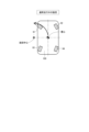
- FIG. 1 is a block diagram of a vehicle travel control device according to this embodiment
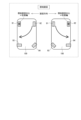
- FIG. 2A is a diagram for explaining turning during normal running of an independently steered vehicle
- FIG. 2B is a diagram for explaining a pivot turn in an independently steered vehicle
- FIG. 3 is a diagram for explaining an example of calculation of the steering angle in turning during normal running.
- FIG. 4 is a diagram for explaining the problem of forward parallel parking
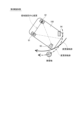
- FIG. 5 is a diagram for explaining a turning problem in a comparative example
- FIG. 6 is a diagram showing the turning motion in forward parallel parking of the four-wheel independent steering vehicle according to the first embodiment
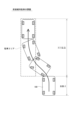
- FIG. 7 is a diagram showing the pivot turning operation of the four-wheel independent steering vehicle following FIG.
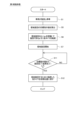
- FIG. 8 is a flowchart of forward parallel parking according to the first embodiment
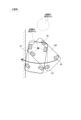
- FIG. 9 is a diagram showing obstacle detection and information presentation according to the second embodiment
- FIG. 10 is a diagram showing an operation example when an obstacle is detected according to the second embodiment
- FIG. 11 is a diagram for explaining a super pivot turn
- FIG. 12 is a diagram showing detection of a parking area according to the third embodiment
- FIG. 13 is a flow chart of forward parallel parking according to the second and third embodiments
- FIG. 14 is a diagram showing a pivot turning operation according to the fourth embodiment
- FIG. 15 is a flowchart of forward parallel parking according to the fourth embodiment
- FIG. 16 is a diagram of a universal three-wheeled vehicle to which a vehicle running control device of another embodiment is applied;
- FIG. 17 is a diagram showing a turning motion in forward parallel parking of a universal three-wheeled vehicle according to another embodiment,
- FIG. 18 is a diagram showing the pivot turning operation of the universal three-wheeled vehicle following FIG.
- the first embodiment is the basic form, and the second to fourth embodiments are those in which optional functions are added to the first embodiment.
- the first to fourth embodiments are collectively referred to as "this embodiment".
- the vehicle running control device of this embodiment controls the running of the vehicle in an independently steered vehicle in which each tire can be steered independently.
- the vehicle travel control device controls travel of the vehicle in a universal three-wheeled vehicle.
- the independent steering vehicle and the swivel three-wheeled vehicle are not limited to those driven by a driver, and include self-driving vehicles.
- each wheel is steered independently to enable turning with a defined turning center and on-the-spot turning.
- FIG. 1 A configuration of a vehicle travel control device 10 according to the present embodiment will be described with reference to FIGS. 1 to 3.
- FIG. 1 In the independently steered vehicle 100 shown in FIG. 1, all four tires 91-94 can be steered independently.
- Each tire 91-94 is equipped with an in-wheel motor ("IWM” in the drawing) and a brake mechanism that generate braking and driving force, and a steering mechanism that steers the tires.
- IWM in-wheel motor
- the front left wheel 91 is labeled "FL”
- the front right wheel 92 is labeled "FR”
- the rear left wheel 93 is labeled "RL”
- the rear right wheel 94 is labeled "RR”.
- the vehicle 100 is equipped with at least a vehicle characteristic storage device 20 that stores vehicle characteristics.
- vehicle characteristics stored in the vehicle characteristics storage device 20 include vehicle dimensions such as wheelbase and tread width.
- the surroundings monitoring device 30, the surroundings information presentation device 40, the parking area detection device 50, and the vehicle direction detection device 60 other than the vehicle characteristic storage device 20 are appropriately provided in the vehicle to which the second to fourth embodiments are applied. Functions of these devices will be described later in the description of the second to fourth embodiments.
- the vehicle running control device 10 includes a turning instruction section 11 , a pivot turning instruction section 12 , a turning angle control section 15 and a braking/driving force control section 16 .
- the turning instruction unit 11 instructs a turning direction and a turning radius in turning during normal running.
- the pivot turn instructing unit 12 instructs a "pivot turn" to drive the other tires centering on one of the tires when the vehicle turns, using a target instruction value.
- the point outside the vehicle becomes the turning center when turning during normal driving, similar to that of a general vehicle.
- a point on the left side of the vehicle is the turning center.
- the independently steered vehicle 100 is capable of pivot turning with any one tire as the turning center.
- the pivot turn instruction unit 12 determines the center of the pivot turn according to the turning direction.
- the left front wheel 91 is the center of the pivot turn, and the other tires 92, 93, and 94 are steered in the tangential direction of the turning circle to drive the vehicle.
- the right front wheel 92 should be the center of the pivot turn, and the other tires 91, 93 and 94 should be steered and driven in the tangential direction of the turning circle. Then, turn so that the rear part of the vehicle swings to the right.
- the steering angle control unit 15 and the braking/driving force control unit 16 acquire vehicle characteristics from the vehicle characteristics storage device 20 .
- the steering angle control unit 15 outputs a command signal to the steering mechanism so as to individually steer the tires 91 to 94 according to the center of the pivot turn instructed by the pivot turn instructing unit 12 .
- the braking/driving force control unit 16 outputs command signals to the in-wheel motors and brake mechanisms so as to individually brake/drive the tires 91-94.
- the steering angle control unit 15 and the braking/driving force control unit 16 calculate the steering angle and driving direction of each tire 91-94 from the target command value, and turn the vehicle on a pivot turn.
- FIG. 3 shows an example of the steering angle calculation by the steering angle control unit 15 when turning during normal running.
- XY coordinates are defined with the center of gravity of the vehicle as the origin (0, 0), the lateral axis of the vehicle as the x axis, and the longitudinal axis of the vehicle as the y axis.
- the x-axis is positive on the right and negative on the left, and the y-axis is positive on the front and negative on the back.
- the steering angle is calculated so that the rotation direction of each tire 91-94 is perpendicular to the straight line connecting the center of each tire 91-94 and the turning center.
- the wheelbase L and tread widths Df and Dr of the vehicle are obtained from the vehicle characteristic storage device 20.
- the distance from the center of gravity to the axes of the front wheels 91 and 92 in the y-axis direction is represented by Lf
- the distance from the center of gravity to the axes of the rear wheels 93 and 94 is represented by Lr.
- the steering angles .delta.FL, .delta.FR, .delta.RL, and .delta.RR of the tires 91-94 are positive in the counterclockwise direction and expressed by tangent values according to equations (2.1) to (2.4).
- the subscripts "FL, FR, RL, RR" in FIG. 3 are described in normal letters in the specification.
- tan ⁇ FL (Lf-y1)/ ⁇
- -(Df/2) ⁇ ... (2.1) tan ⁇ FR (Lf ⁇ y1)/ ⁇
- +(Df/2) ⁇ (2.2) tan ⁇ RL ⁇ (Lr+y1)/ ⁇
- ⁇ (Dr/2) ⁇ ... (2.3) tan ⁇ RR ⁇ (Lr+y1)/ ⁇
- Parallel parking in reverse is generally a difficult driving maneuver.
- the vehicle in order to park in reverse, the vehicle must stop and change the direction of travel from forward to reverse, which creates psychological pressure to keep the following vehicle waiting. Therefore, it is desirable to be able to park in parallel while moving forward as much as possible.
- Patent Document 1 Japanese Patent Application Laid-Open No. 2010-288449
- the left and right front wheels are driven in different directions, and the left and right rear wheels are steered to turn the vehicle. do.
- the center of rotation of the front wheels 91 and 92 is the middle point of the left and right front wheels.
- the center of rotation of the rear wheels 93, 94 is on the right front of the vehicle, but is not precisely defined. Since the center of rotation of the front wheels and the center of rotation of the rear wheels are different, the tires are subjected to a side-slip load during driving, which increases the required driving force and loss.
- the turning center of the rear wheels is not defined, depending on the setting of the turning center, the vehicle may come into contact with the edge of the road or deviate greatly from the edge of the road when turning.
- the own vehicle 100 turns left while moving forward, enters a parking area between other vehicles 801 and 802 parked in front and behind, and stops.
- the vehicle running control device 10 performs a pivot turn with the left front wheel 91 as the turning center and turns the vehicle 100 according to the target instruction value of the pivot turn instruction unit 12 .
- a thin dashed arc arrow attached to the rear wheels 93 and 94 indicates the steering direction.
- the thick solid line arrows attached to the right front wheel 92 and the rear wheels 93 and 94 represent the driving force.
- the vehicle travel control device 10 steers the tires (mainly the rear wheels 93 and 94) to their initial positions. Forward parallel parking is thus completed.
- parallel parking is possible in a parking area that is at least about 1.2 times the total vehicle length ⁇ .
- the length of about 1.2 times corresponds to the distance required for parallel parking in reverse. That is, in the first embodiment, parallel parking can be performed in a parking space equivalent to that of reverse parking and more quickly than reverse parking.
- the steering angle of the other tires 92 to 94 is adjusted so that the left front wheel 91 becomes the center of the pivot turn. You can park by the side of the road.
- the flowchart of FIG. 8 shows the forward parallel parking routine according to the first embodiment.
- the symbol "S" means step. 8, 13, and 15, substantially the same steps are denoted by the same step numbers, and descriptions thereof are omitted. Therefore, step numbers may not be consecutive.
- the vehicle 100 turns and stops.
- the pivot turn instruction unit 12 calculates a target instruction value for pivot turn.
- the steering angle control unit 15 steers the tires 91-94 so that the vehicle can turn at the pivot turning center (for example, the left front wheel 91) instructed by the pivot turning instructing unit 12.
- FIG. 7 the steering angle control section 15 and the braking/driving force control section 16 start a pivot turn.
- the independently steered vehicle 100 utilizes the independent steering of the tires 91 to 94 and the pivot turning by braking/driving, so that even a narrow parking space can be quickly and easily maneuvered. Forward parallel parking is possible.
- optional functions of the second to fourth embodiments added to the first embodiment will be described in order.
- a vehicle 100 is provided with a surroundings monitoring device 30 that detects obstacles around the vehicle 100 and a surroundings information presentation device 40 that presents information about the surroundings of the vehicle 100 to passengers.
- the perimeter monitoring device 30 is a sonar, a camera, a LiDAR, or the like.
- the peripheral information presentation device 40 outputs a beep sound or displays an alert screen on the monitor.
- a star-shaped polygonal mark represents the peripheral information presentation device 40 .
- the steering angle control unit 15 and the braking/driving force control unit 16 detect the obstacle based on the position of the obstacle and the future vehicle trajectory. Calculate the presence or absence of contact with an object. As a result, when contact with an obstacle is predicted, the steering angle control section 15 and the braking/driving force control section 16 cause the peripheral information presentation device 40 to present that information. Further, the turning angle control unit 15 and the braking/driving force control unit 16 avoid contact with the obstacle by stopping the pivot turn at that place. The steering angle control unit 15 and the braking/driving force control unit 16 cause the peripheral information presentation device 40 to present information such as redoing a turn and changing a parking place.
- the direction of movement of the vehicle 100 is the blind spot from the position of the passenger, so the surroundings monitoring device 30 such as sonar detects obstacles in the surroundings and informs the driver to prevent contact. be able to.
- the peripheral information presentation device 40 informs the crew of whether or not the pivot turn is permitted before the pivot turn is started, recovery operations such as re-turning can be facilitated.
- the pivot turn instruction unit 12 changes the pivot turn center from the left front wheel 91 to the right front wheel 92 to avoid contact with the obstacle. Change the trajectory of the turn.
- the independent steering vehicle 100 can also make a "super pivot turn". As shown in FIG. 11, in a super pivot turn, each tire 91-94 is steered in the tangential direction of the turning circle with the center of gravity of the vehicle 100 as the turning center. When the vehicle 100 rotates on the spot by the super pivot turn and rotates until the trajectory of the pivot turn reaches a position where it does not contact an obstacle, it can be returned to the pivot turn and the independent steered vehicle 100 can be moved to the side of the road.
- the vehicle 100 is provided with a parking area detection device 50 that detects the parking area.
- the parking area detection device 50 may be a sonar, a camera, a LiDAR, or the like, and the perimeter monitoring device 30 may also function as the parking area detection device 50 .
- the parking area detection device 50 detects a parking area based on, for example, white lines, guardrails, sidewalks, and the like.
- the pivot turn instruction unit 12 calculates a pivot turn target instruction value based on the parking area detected by the parking area detection device 50 . Automatic parking is possible by automatically turning to the detected parking area.
- the flowchart of FIG. 13 shows a forward parallel parking routine that combines the second embodiment and the third embodiment. Steps relating to the second embodiment are denoted by letter A, and steps relating to the third embodiment are denoted by letter B at the end of the step number. Description of steps that are substantially the same as in FIG. 8 will be omitted.
- S1A the presence or absence of an obstacle is detected by the perimeter monitoring device 30 before the pivot turn, and it is confirmed whether or not parking is possible during the pivot turn.
- S3A it is determined whether parking is possible. If parking is possible and YES is determined in S3A, the pivot turn instruction unit 12 calculates a pivot turn target instruction value based on the parking area detected by the parking area detector 50 in S5B.
- S8A After S6 and S7, in S8A, the presence or absence of an obstacle is detected by the perimeter monitoring device 30 during the pivot turn. At S9A, it is determined whether or not there is an obstacle. If there is no obstacle and it is determined as NO in S9A, it is determined in S11 whether the pivot turn has been completed up to the target command value. If NO in S11, the process returns to S7.
- the unit 12 causes the peripheral information presentation device 40 to present information such as redoing a turn or changing a parking place.
- the vehicle 100 is provided with a vehicle direction detection device 60 that detects and stores the yaw angle of the vehicle 100 .
- the vehicle direction detection device 60 is a yaw rate sensor.
- the upper side of FIG. 14 shows a state in which the vehicle 100 turns from forward movement.
- the left-right axis of the vehicle 100 before turning is represented by the x-axis
- the front-rear axis is represented by the y-axis.
- the rotation angle from the y-axis to the yt-axis is the initial yaw angle ⁇ yo after turning.
- the lower side of FIG. 14 shows a state in which the vehicle 100 makes a pivot turn after turning.
- the target yaw angle after the pivot turn is expressed as ⁇ y * .
- the target yaw angle ⁇ y * is a value other than 0 when parallel parking on a curved road or when parking in a parking space provided diagonally with respect to the straight ahead direction.
- the pivot turn instruction unit 12 calculates a target instruction value so as to provide a yaw angle having the same absolute value as the initial yaw angle ⁇ yo detected and stored by the vehicle direction detection device 60 in the opposite direction. As a result, it is possible to prevent an overshoot in a pivot turn without using the perimeter monitoring device 30, the parking area detection device 50, or the like.
- the flowchart of FIG. 15 shows the forward parallel parking routine according to the fourth embodiment. Steps relating to the fourth embodiment are marked with the letter C at the end of the step number. Description of steps that are substantially the same as in FIG. 8 will be omitted.
- the vehicle direction detection device 60 detects and stores the initial yaw angle ⁇ yo after turning.
- S6, S7, S11 and S12 are the same as in FIG.
- the independently steered vehicle 100 is not limited to a four-wheel independently steered vehicle, and may be any vehicle in which three or more wheels can be steered independently. Further, as shown in FIG. 16 , the vehicle travel control device of the present disclosure is applied to a “universal three-wheeled vehicle” 100T that has two front wheels 91 and 92 and one rear wheel 95 and that the rear wheel 95 can be freely steered. may be
- 17 and 18 show the turning and pivot turning operations in forward parallel parking of the universal three-wheeled vehicle 100T. 17 and 18 correspond to FIGS. 6 and 7 of the four-wheel independent steering vehicle 100.
- FIG. 17 As shown in FIG. 17, the own vehicle 100T turns left while moving forward, enters a parking area between other vehicles 801 and 802 parked in front and behind, and stops.
- a pivot turn with the left front wheel 91 as the turning center is performed.
- the center of the pivot turn is determined according to the turning direction.
- a thin dashed circular arc arrow attached to the rear wheel 95 indicates the steering direction, and a thick solid linear arrow indicates the driving force.
- each tire mainly the rear wheel 95
- the swivel three-wheeled vehicle 100T also uses pivot turning, so that forward parallel parking can be quickly and easily performed even in a narrow parking space.
- Each controller and technique described in this disclosure can be performed by a dedicated computer provided by configuring a processor and memory programmed to perform one or more functions embodied by a computer program. may be implemented.
- each of the controls and techniques described in this disclosure may be implemented by a dedicated computer provided by configuring the processor with one or more dedicated hardware logic circuits.
- each controller and technique described in this disclosure is a combination of a processor and memory programmed to perform one or more functions and a processor configured by one or more hardware logic circuits. may be implemented by one or more dedicated computers configured by The computer program may also be stored as computer-executable instructions on a computer-readable non-transitional tangible recording medium.
Landscapes
- Engineering & Computer Science (AREA)
- Transportation (AREA)
- Mechanical Engineering (AREA)
- Chemical & Material Sciences (AREA)
- Combustion & Propulsion (AREA)
- Automation & Control Theory (AREA)
- Human Computer Interaction (AREA)
- Steering Control In Accordance With Driving Conditions (AREA)
- Control Of Driving Devices And Active Controlling Of Vehicle (AREA)
Abstract
車両走行制御装置(10)は、三輪以上のタイヤ(91-94)が独立して転舵可能な独立転舵車両(100)において車両(100)の走行を制御する。旋回指示部(11)は、通常走行中の旋回を指示する。信地旋回指示部(12)は、車両の転向時にいずれか一つのタイヤを旋回中心として他のタイヤを駆動させる信地旋回を目標指示値により指示する。転舵角制御部(15)及び制駆動力制御部(16)は、車両特性記憶装置(20)から車両特性を取得する。信地旋回指示部(12)から指示された信地旋回の中心に応じて、転舵角制御部(15)は各タイヤ(91-94)を個別に転舵させ、制駆動力制御部(16)は各タイヤ(91-94)を個別に制駆動させる。転舵角制御部(15)及び制駆動力制御部(16)は、目標指示値から各タイヤの転舵角及び駆動方向を算出し、車両を信地旋回させる。
Description
本出願は、2021年11月12日に出願された日本出願番号2021-185158号に基づくものであり、ここにその記載内容を援用する。
本開示は、車両走行制御装置に関する。
従来、駐車スペースへの前進縦列駐車を支援する技術が知られている。例えば特許文献1に開示された駆動支援装置では、左右の前輪はハブモータによりそれぞれ異なる方向に駆動される。左右の後輪は、駐車スペースに向かう方向に転舵される。狭い駐車スペースへも僅かな操車の手間で駐車を行えるようにすることが図られている。
特許文献1の図1の状態での車両の水平方向の回転について、前輪の回転中心は左右の前輪の中点であり、後輪の回転中心は車両右前方の点である。前輪の回転中心と後輪の回転中心とが異なるため、駆動時にタイヤに横滑りの負荷がかかり、必要な駆動力やロスが大きくなる。また走行軌跡が制御できない。
本開示の目的は、狭い駐車スペースでも素早く前進縦列駐車を可能とする車両走行制御装置を提供することにある。
本開示による車両走行制御装置は、三輪以上のタイヤが独立して転舵可能な独立転舵車両、又は、二つの前輪と一つの後輪を備え、後輪が自在に転舵可能な自在三輪車両において車両の走行を制御する。この車両走行制御装置は、旋回指示部と、信地旋回指示部と、転舵角制御部及び制駆動力制御部と、を備える。
旋回指示部は、通常走行中の旋回を指示する。信地旋回指示部は、車両の転向時にいずれか一つのタイヤを旋回中心として他のタイヤを駆動させる信地旋回を目標指示値により指示する。
転舵角制御部及び制駆動力制御部は、車両特性記憶装置から車両特性を取得する。信地旋回指示部から指示された信地旋回の中心に応じて、転舵角制御部は各タイヤを個別に転舵させ、制駆動力制御部は各タイヤを個別に制駆動させる。
転舵角制御部及び制駆動力制御部は、目標指示値から各タイヤの転舵角及び駆動方向を算出し、車両を信地旋回させる。
独立転舵車両において各タイヤの独立した転舵及び制駆動による信地旋回を利用することで、狭い駐車スペースでも素早く簡単に前進縦列駐車が可能となる。また、自在三輪車両において一つの後輪の転舵及び制駆動による信地旋回を利用することで、狭い駐車スペースでも素早く簡単に前進縦列駐車が可能となる。
本開示についての上記目的及びその他の目的、特徴や利点は、添付の図面を参照しながら下記の詳細な記述により、より明確になる。その図面は、
図1は、本実施形態による車両走行制御装置のブロック図であり、
図2Aは、独立転舵車両での通常走行中の旋回を説明する図であり、
図2Bは、独立転舵車両での信地旋回を説明する図であり、
図3は、通常走行中の旋回における転舵角の計算例を説明する図であり、
図4は、前進縦列駐車の課題を説明する図であり、
図5は、比較例による旋回の課題を説明する図であり、
図6は、第1実施形態による四輪独立転舵車両の前進縦列駐車における旋回動作を示す図であり、
図7は、図6に続く四輪独立転舵車両の信地旋回動作を示す図であり、
図8は、第1実施形態による前進縦列駐車のフローチャートであり、
図9は、第2実施形態による障害物の検出及び情報提示を示す図であり、
図10は、第2実施形態による障害物検出時の動作例を示す図であり、
図11は、超信地旋回を説明する図であり、
図12は、第3実施形態による駐車域の検出を示す図であり、
図13は、第2実施形態及び第3実施形態による前進縦列駐車のフローチャートであり、
図14は、第4実施形態による信地旋回動作を示す図であり、
図15は、第4実施形態による前進縦列駐車のフローチャートであり、
図16は、その他の実施形態の車両走行制御装置が適用される自在三輪車両の図であり、
図17は、その他の実施形態による自在三輪車両の前進縦列駐車における旋回動作を示す図であり、
図18は、図17に続く自在三輪車両の信地旋回動作を示す図である。
本開示の実施形態による車両走行制御装置を図面に基づいて説明する。第1実施形態が基本形態であり、第2~第4実施形態は第1実施形態に対しオプション機能が付加されたものである。第1~第4実施形態を包括して「本実施形態」という。本実施形態の車両走行制御装置は、各タイヤが独立して転舵可能な独立転舵車両において車両の走行を制御する。また、後述する「その他の実施形態」では、車両走行制御装置は、自在三輪車両において車両の走行を制御する。独立転舵車両や自在三輪車両は、ドライバが運転するものに限らず自動運転車両も含まれる。
従来、一般的な車両は左右対のタイヤがリンクを介して機械的に結合されており、ステアリングの操舵によってタイヤが転舵する。今後、ステアリングと左右対タイヤのリンクとが機械的に分離したステアバイワイヤや、左右前輪に加え、左右後輪も独立して転舵可能な四輪独立転舵車両に発展していくと考えられる。例えば四輪独立転舵車両では、各輪が独立して転舵することで、旋回中心を規定した旋回やその場回転等が可能である。
(第1実施形態)
図1~図3を参照し、本実施形態による車両走行制御装置10の構成を説明する。図1に示す独立転舵車両100は、四つのタイヤ91-94が全て独立に転舵可能である。各タイヤ91-94は、制駆動力を発生させるインホイールモータ(図中「IWM」)及びブレーキ機構と、タイヤを転舵させる転舵機構とが備わっている。左前輪91に「FL」、右前輪92に「FR」、左後輪93に「RL」、右後輪94に「RR」と記す。
図1~図3を参照し、本実施形態による車両走行制御装置10の構成を説明する。図1に示す独立転舵車両100は、四つのタイヤ91-94が全て独立に転舵可能である。各タイヤ91-94は、制駆動力を発生させるインホイールモータ(図中「IWM」)及びブレーキ機構と、タイヤを転舵させる転舵機構とが備わっている。左前輪91に「FL」、右前輪92に「FR」、左後輪93に「RL」、右後輪94に「RR」と記す。
車両100には、車両走行制御装置10の他に、車両特性を記憶した車両特性記憶装置20が少なくとも搭載されている。車両特性記憶装置20が記憶する車両特性には、ホイールベースやトレッド幅等の車両寸法等が含まれる。車両特性記憶装置20以外の周辺監視装置30、周辺情報提示装置40、駐車域検出装置50及び車両方向検出装置60は、第2~第4実施形態が適用される車両に適宜設けられている。これらの装置の機能については第2~第4実施形態の説明において後述する。
車両走行制御装置10は、旋回指示部11、信地旋回指示部12、転舵角制御部15及び制駆動力制御部16を備える。旋回指示部11は、通常走行中の旋回における旋回方向及び旋回半径を指示する。信地旋回指示部12は、車両の転向時にいずれか一つのタイヤを中心として他のタイヤを駆動させる「信地旋回」を目標指示値により指示する。
図2Aに示すように、一般車両と同様の通常走行中の旋回では車両外部の点が旋回中心となる。例えば左旋回の場合、車両の左側方の点が旋回中心となる。図2Bに示すように、独立転舵車両100では、いずれか一つのタイヤを旋回中心とした信地旋回が可能である。信地旋回指示部12は、旋回方向に応じて、信地旋回の中心を決定する。
例えば左旋回した後、道路左端に寄せて縦列駐車する場合、左前輪91を信地旋回中心とし、他のタイヤ92、93、94を旋回円の接線方向に転舵して駆動させることで、車両後部を左方に振るように転向する。一方、右旋回した後、道路右端に寄せて縦列駐車する場合、右前輪92を信地旋回中心とし、他のタイヤ91、93、94を旋回円の接線方向に転舵して駆動させることで、車両後部を右方に振るように転向する。
転舵角制御部15及び制駆動力制御部16は、車両特性記憶装置20から車両特性を取得する。転舵角制御部15は、信地旋回指示部12から指示された信地旋回の中心に応じて、各タイヤ91-94を個別に転舵させるように転舵機構に指令信号を出力する。制駆動力制御部16は、各タイヤ91-94を個別に制駆動させるようにインホイールモータ及びブレーキ機構に指令信号を出力する。転舵角制御部15及び制駆動力制御部16は、目標指示値から各タイヤ91-94の転舵角及び駆動方向を算出し、車両を信地旋回させる。
図3に、通常走行中の旋回時における転舵角制御部15による転舵角の計算例を示す。車両重心を原点(0,0)とし、車両左右軸をx軸、車両前後軸をy軸とするxy座標を定義する。x軸は右を正、左を負とし、y軸は前を正、後を負とする。旋回中心の座標を(x1,y1)とする。道路左端に縦列駐車するために左旋回する状況を想定した場合、旋回中心は車両の左側になるため、「x1<0」である。
各タイヤ91-94の回転方向が、各タイヤ91-94の中心と旋回中心とを結んだ直線に対して垂直になるように転舵角が計算される。旋回半径Rtは、旋回中心と重心との距離であり、式(1)で表される。
Rt=√(x12+y12) ・・・(1)
Rt=√(x12+y12) ・・・(1)
車両のホイールベースL及びトレッド幅Df、Drは、車両特性記憶装置20から取得される。y軸方向における重心から前輪91、92の軸までの距離をLf、重心から後輪93、94の軸までの距離をLrと表す。各タイヤ91-94の転舵角δFL、δFR、δRL、δRRは、時計反回転方向を正とし、式(2.1)~(2.4)によりタンジェント値で表される。図3中の下付文字「FL、FR、RL、RR」を明細書中では通常文字で記載する。
tanδFL= (Lf-y1)/{|x1|-(Df/2)}
・・・(2.1)
tanδFR= (Lf-y1)/{|x1|+(Df/2)}
・・・(2.2)
tanδRL=-(Lr+y1)/{|x1|-(Dr/2)}
・・・(2.3)
tanδRR=-(Lr+y1)/{|x1|+(Dr/2)}
・・・(2.4)
・・・(2.1)
tanδFR= (Lf-y1)/{|x1|+(Df/2)}
・・・(2.2)
tanδRL=-(Lr+y1)/{|x1|-(Dr/2)}
・・・(2.3)
tanδRR=-(Lr+y1)/{|x1|+(Dr/2)}
・・・(2.4)
次に図4~図7を参照し、前進縦列駐車における従来技術の課題、及び、第1実施形態による課題解決について説明する。一般にバックでの縦列駐車は難しい運転操作である。また、バック駐車をするためには一旦停止をして前進からバックに走行方向を切り替えるため、後続車両を待たせるという心理的なプレッシャが生じる。したがって、できる限り前進しながらそのまま縦列駐車できることが望ましい。
しかし、図4に示すように、前進で縦列駐車を完了するためには車両全長λの約3倍以上の長さの駐車エリアが必要となる。そのため、狭いスペースには駐車できないという問題がある。
この問題に対し、特許文献1(特開2010-288449号公報)の従来技術に相当する比較例では、左右の前輪がそれぞれ異なる方向に駆動され、左右の後輪が転舵されて車両が旋回する。図5に示すように、前輪91、92の回転中心は左右の前輪の中点である。後輪93、94の回転中心は車両右前方にあるが、正確に定義されない。前輪の回転中心と後輪の回転中心とが異なるため、駆動時にタイヤに横滑りの負荷がかかり、必要な駆動力やロスが大きくなる。また、後輪の旋回中心が定義されないため、旋回中心の設定次第では、旋回時に車両が道路端に接触したり、道路端から大きく乖離したりするおそれがある。
次に図6、図7を参照し、四輪独立転舵車両100の前進縦列駐車における旋回及び信地旋回の動作を説明する。図6に示すように、自車両100は前進しながら左旋回し、前後に駐車している他車両801、802の間の駐車エリアに進入して、停車する。
続いて図7の上側に示すように、信地旋回指示部12の目標指示値により、車両走行制御装置10は、左前輪91を旋回中心として信地旋回を行い、車両100を転向させる。後輪93、94に付された細破線の円弧矢印は転舵方向を表す。右前輪92及び後輪93、94に付された太実線の直線矢印は駆動力を表す。、図7の下側に示すように、信地旋回後、車両走行制御装置10は、各タイヤ(主に後輪93、94)を初期位置に戻すように転舵させる。こうして前進縦列駐車が完了する。
第1実施形態によると、最短で車両全長λの約1.2倍の長さの駐車エリアで縦列駐車が可能である。約1.2倍という長さは、バックでの縦列駐車に必要な距離に相当する。つまり第1実施形態では、バック駐車と同等の駐車スペースで、且つ、バック駐車よりも素早く縦列駐車を行うことができる。
また、特許文献1の従来技術に対し、第1実施形態では左前輪91が信地旋回の中心となるように他のタイヤ92-94の転舵角を調整することで、車両100を確実に道路端へ寄せて駐車することができる。
図8のフローチャートに、第1実施形態による前進縦列駐車のルーチンを示す。フローチャートの説明で記号「S」はステップを意味する。図8、図13、図15で実質的に同一のステップには同一のステップ番号を付して説明を省略する。そのため、ステップ番号は連続しない場合がある。
S1では車両100が旋回して停車する。S5で信地旋回指示部12は信地旋回の目標指示値を算出する。S6で転舵角制御部15は、信地旋回指示部12から指示された信地旋回中心(例えば左前輪91)で旋回できるように各タイヤ91-94を転舵させる。S7で転舵角制御部15及び制駆動力制御部16は信地旋回を開始する。
S11では目標指示値まで信地旋回が完了したか、すなわち駐車完了したか判断され、NOの場合、判断が繰り返される。信地旋回が完了し、S11でYESと判定されると、S12で転舵角制御部15及び制駆動力制御部16は、信地旋回するために転舵したタイヤを初期位置に戻す。
以上のように基本形態である第1実施形態によると、独立転舵車両100において各タイヤ91-94の独立した転舵及び制駆動による信地旋回を利用することで、狭い駐車スペースでも素早く簡単に前進縦列駐車が可能となる。続いて、第1実施形態に付加される第2~第4実施形態のオプション機能について順に説明する。
(第2実施形態)
図1及び図9を参照する。第2実施形態では、車両100の周囲の障害物を検出する周辺監視装置30と、車両100の周囲の情報を乗員に提示する周辺情報提示装置40とが車両100に設けられている。例えば周辺監視装置30はソナー、カメラ、LiDAR等である。例えば周辺情報提示装置40は、ビープ音を出力したり、モニターにアラート画面を表示したりする。図9では、星型多角形マークが周辺情報提示装置40を表す。
図1及び図9を参照する。第2実施形態では、車両100の周囲の障害物を検出する周辺監視装置30と、車両100の周囲の情報を乗員に提示する周辺情報提示装置40とが車両100に設けられている。例えば周辺監視装置30はソナー、カメラ、LiDAR等である。例えば周辺情報提示装置40は、ビープ音を出力したり、モニターにアラート画面を表示したりする。図9では、星型多角形マークが周辺情報提示装置40を表す。
転舵角制御部15及び制駆動力制御部16は、信地旋回開始前または信地旋回中に周辺監視装置30が障害物を検出したとき、障害物の位置と今後の車両軌跡とから障害物との接触の有無を計算する。その結果、障害物との接触が予測される場合、転舵角制御部15及び制駆動力制御部16は、その情報を周辺情報提示装置40に提示させる。また、転舵角制御部15及び制駆動力制御部16は、その場所での信地旋回を中止することで、障害物との接触を回避する。転舵角制御部15及び制駆動力制御部16は、旋回をやり直す、駐車場所を変える等の情報を周辺情報提示装置40に提示させる。
ドライバが車両100を運転する場合、信地旋回の移動方向は乗員位置から死角になっているため、ソナー等の周辺監視装置30で周辺の障害物を検出してドライバに伝えることで接触を防ぐことができる。また、信地旋回開始前に周辺情報提示装置40が信地旋回の可否を乗員に知らせることで、旋回をし直す等のリカバリー動作が容易になる。
図10を参照し、第2実施形態による障害物検出時の動作例について説明する。障害物との接触が予測される場合、例えば信地旋回指示部12は、信地旋回の中心を左前輪91から右前輪92に変更することで、障害物との接触を避けるように信地旋回の軌跡を変更する。
或いは、障害物との接触を避ける方法として、独立転舵車両100は「超信地旋回」をすることも可能である。図11に示すように、超信地旋回では、車両100の重心を旋回中心として各タイヤ91-94が旋回円の接線方向に転舵される。超信地旋回によりその場回転し、信地旋回の軌跡が障害物と接触しない位置になるまで回転したら、信地旋回に戻して独立転舵車両100を道路端に寄せることができる。
(第3実施形態)
図1及び図12を参照する。第3実施形態では、第2実施形態の構成に加え、駐車域を検出する駐車域検出装置50が車両100に設けられている。例えば駐車域検出装置50はソナー、カメラ、LiDAR等であり、周辺監視装置30が駐車域検出装置50の機能を兼ねてもよい。駐車域検出装置50は、例えば白線、ガードレール、歩道等に基づいて駐車域を検出する。
図1及び図12を参照する。第3実施形態では、第2実施形態の構成に加え、駐車域を検出する駐車域検出装置50が車両100に設けられている。例えば駐車域検出装置50はソナー、カメラ、LiDAR等であり、周辺監視装置30が駐車域検出装置50の機能を兼ねてもよい。駐車域検出装置50は、例えば白線、ガードレール、歩道等に基づいて駐車域を検出する。
信地旋回指示部12は、駐車域検出装置50が検出した駐車域に基づき信地旋回の目標指示値を算出する。検出された駐車域まで自動的に信地旋回が行われることで、自動駐車が可能となる。
図13のフローチャートに、第2実施形態及び第3実施形態を組み合わせた前進縦列駐車のルーチンを示す。第2実施形態に関するステップにはA、第3実施形態に関するステップにはBの文字をステップ番号の末尾に記す。図8と実質的に同様のステップについては説明を省略する。S1の後、S2Aでは、信地旋回前に周辺監視装置30で障害物の有無を検出し、信地旋回での駐車可否を確認する。S3Aでは駐車可能か否か判断される。駐車可能であり、S3AでYESと判定されると、S5Bで信地旋回指示部12は、駐車域検出装置50により検出された駐車域に基づき信地旋回の目標指示値を算出する。
続いてS6、S7の後、S8Aでは信地旋回中に周辺監視装置30で障害物の有無を検出する。S9Aでは障害物があるか否か判断される。障害物が無く、S9AでNOと判定されると、S11で目標指示値まで信地旋回が完了したか判断される。S11でNOの場合、S7の次に戻る。
信地旋回前のS3AでNO、すなわち「駐車可能でない」と判定された場合、又は、信地旋回中のS9AでYES、すなわち「障害物あり」と判定された場合、S10Aで信地旋回指示部12は、旋回をやり直す、駐車場所を変える等の情報を周辺情報提示装置40に提示させる。
(第4実施形態)
図1及び図14を参照する。第4実施形態では、車両100のヨー角を検出し記憶する車両方向検出装置60が車両100に設けられている。例えば、車両方向検出装置60はヨーレートセンサである。図14の上側に、車両100が前進から旋回した状態を示す。旋回前の車両100の左右軸をx軸、前後軸をy軸と表し、旋回後の車両100の左右軸をxt軸、前後軸をyt軸と表す。y軸からyt軸までの回転角度が旋回後の初期ヨー角θyoとなる。
図1及び図14を参照する。第4実施形態では、車両100のヨー角を検出し記憶する車両方向検出装置60が車両100に設けられている。例えば、車両方向検出装置60はヨーレートセンサである。図14の上側に、車両100が前進から旋回した状態を示す。旋回前の車両100の左右軸をx軸、前後軸をy軸と表し、旋回後の車両100の左右軸をxt軸、前後軸をyt軸と表す。y軸からyt軸までの回転角度が旋回後の初期ヨー角θyoとなる。
図14の下側に、車両100が旋回後に信地旋回した状態を示す。信地旋回後の目標ヨー角をθy*と表す。例えば直線道路の道路端に平行に縦列駐車する場合の目標ヨー角は「θy*=0」となる。ただし、カーブ道路に縦列駐車する場合や、直進方向に対して斜めに設けられた駐車スペースに駐車する場合、目標ヨー角θy*は0以外の値になる。
信地旋回指示部12は、車両100の信地旋回前の初期ヨー角θyoと信地旋回後の目標ヨー角θy*との差分Δθyが信地旋回のヨー角Δθy(=θy*-θyo)となるように信地旋回の目標指示値を算出する。「θy*=0」の場合、「Δθy=-θyo」となる。信地旋回指示部12は、車両方向検出装置60が検出し記憶した初期ヨー角θyoと絶対値が等しいヨー角を反対方向に付与するように目標指示値を算出する。これにより、周辺監視装置30や駐車域検出装置50等を用いず、信地旋回でのオーバーシュートを防ぐことができる。
図15のフローチャートに、第4実施形態による前進縦列駐車のルーチンを示す。第4実施形態に関するステップにはCの文字をステップ番号の末尾に記す。図8と実質的に同様のステップについては説明を省略する。S1の後、S4Cで車両方向検出装置60は、旋回後の初期ヨー角θyoを検出し記憶する。
S5Cで信地旋回指示部12は、「信地旋回のヨー角Δθy=目標ヨー角θy*-初期ヨー角θyo」となるように信地旋回の目標指示値を算出する。S6、S7、S11、S12は図8と同様である。
(その他の実施形態)
(a)独立転舵車両100は四輪独立転舵車両に限らず、三輪以上のタイヤが独立して転舵可能な車両であればよい。また図16に示すように、本開示の車両走行制御装置は、二つの前輪91、92と一つの後輪95を備え、後輪95が自在に転舵可能な「自在三輪車両」100Tに適用されてもよい。
(a)独立転舵車両100は四輪独立転舵車両に限らず、三輪以上のタイヤが独立して転舵可能な車両であればよい。また図16に示すように、本開示の車両走行制御装置は、二つの前輪91、92と一つの後輪95を備え、後輪95が自在に転舵可能な「自在三輪車両」100Tに適用されてもよい。
図17、図18に、自在三輪車両100Tの前進縦列駐車における旋回及び信地旋回の動作を示す。図17、図18は四輪独立転舵車両100の図6、図7に対応する。図17に示すように、自車両100Tは前進しながら左旋回し、前後に駐車している他車両801、802の間の駐車エリアに進入して、停車する。
続いて図18の上側に示すように、左前輪91を旋回中心とする信地旋回が行われる。四輪独立転舵車両100と同様に、信地旋回の中心は旋回方向に応じて決定される。後輪95に付された細破線の円弧矢印は転舵方向を表し、太実線の直線矢印は駆動力を表す。図18の下側に示すように、信地旋回後、各タイヤ(主に後輪95)は初期位置に戻すように転舵される。このように、自在三輪車両100Tも信地旋回を利用することで、狭い駐車スペースでも素早く簡単に前進縦列駐車が可能となる。
以上、本開示はこのような実施形態に限定されるものではなく、その趣旨を逸脱しない範囲において、種々の形態で実施することができる。
本開示に記載の各制御部及びその手法は、コンピュータプログラムにより具体化された一つ乃至は複数の機能を実行するようにプログラムされたプロセッサ及びメモリを構成することによって提供された専用コンピュータにより、実現されてもよい。あるいは、本開示に記載の各制御部及びその手法は、一つ以上の専用ハードウェア論理回路によってプロセッサを構成することによって提供された専用コンピュータにより、実現されてもよい。もしくは、本開示に記載の各制御部及びその手法は、一つ乃至は複数の機能を実行するようにプログラムされたプロセッサ及びメモリと一つ以上のハードウェア論理回路によって構成されたプロセッサとの組み合わせにより構成された一つ以上の専用コンピュータにより、実現されてもよい。また、コンピュータプログラムは、コンピュータにより実行されるインストラクションとして、コンピュータ読み取り可能な非遷移有形記録媒体に記憶されていてもよい。
本開示は実施形態に準拠して記述された。しかしながら、本開示は当該実施形態および構造に限定されるものではない。本開示は、様々な変形例および均等の範囲内の変形をも包含する。また、様々な組み合わせおよび形態、さらには、それらに一要素のみ、それ以上、あるいはそれ以下、を含む他の組み合わせおよび形態も本開示の範疇および思想範囲に入るものである。
Claims (5)
- 三輪以上のタイヤ(91-94)が独立して転舵可能な独立転舵車両(100)、又は、二つの前輪と一つの後輪を備え、後輪が自在に転舵可能な自在三輪車両(100T)において車両の走行を制御する車両走行制御装置であって、
通常走行中の旋回を指示する旋回指示部(11)と、
車両の転向時にいずれか一つのタイヤを旋回中心として他のタイヤを駆動させる信地旋回を目標指示値により指示する信地旋回指示部(12)と、
車両特性記憶装置(20)から車両特性を取得し、前記信地旋回指示部から指示された信地旋回の中心に応じて、各タイヤを個別に転舵させる転舵角制御部(15)、及び、各タイヤを個別に制駆動させる制駆動力制御部(16)と、
を備え、
前記転舵角制御部及び前記制駆動力制御部は、前記目標指示値から各タイヤの転舵角及び駆動方向を算出し、車両を信地旋回させる車両走行制御装置。 - 前記信地旋回指示部は、旋回方向に応じて、信地旋回の中心を決定する請求項1に記載の車両走行制御装置。
- 車両の周囲の障害物を検出する周辺監視装置(30)と、車両の周囲の情報を乗員に提示する周辺情報提示装置(40)と、を備えた車両に搭載され、
前記転舵角制御部及び前記制駆動力制御部は、信地旋回開始前または信地旋回中に前記周辺監視装置が検出した障害物との接触が予測される場合、その情報を前記周辺情報提示装置に提示させる請求項1または2に記載の車両走行制御装置。 - 駐車域を検出する駐車域検出装置(50)を備えた車両に搭載され、
前記信地旋回指示部は、前記駐車域検出装置が検出した駐車域に基づき信地旋回の目標指示値を算出する請求項3に記載の車両走行制御装置。 - 車両のヨー角を検出し記憶する車両方向検出装置(60)を備えた車両に搭載され、
前記信地旋回指示部は、車両の信地旋回前の初期ヨー角(θyo)と信地旋回後の目標ヨー角(θy*)との差分(Δθy)が信地旋回のヨー角となるように信地旋回の目標指示値を算出する請求項1~4のいずれか一項に記載の車両走行制御装置。
Priority Applications (2)
| Application Number | Priority Date | Filing Date | Title |
|---|---|---|---|
| CN202280074786.4A CN118302346A (zh) | 2021-11-12 | 2022-11-08 | 车辆行驶控制装置 |
| US18/659,903 US20240286602A1 (en) | 2021-11-12 | 2024-05-09 | Vehicle travel control device |
Applications Claiming Priority (2)
| Application Number | Priority Date | Filing Date | Title |
|---|---|---|---|
| JP2021185158A JP2023072538A (ja) | 2021-11-12 | 2021-11-12 | 車両走行制御装置 |
| JP2021-185158 | 2021-11-12 |
Related Child Applications (1)
| Application Number | Title | Priority Date | Filing Date |
|---|---|---|---|
| US18/659,903 Continuation US20240286602A1 (en) | 2021-11-12 | 2024-05-09 | Vehicle travel control device |
Publications (1)
| Publication Number | Publication Date |
|---|---|
| WO2023085249A1 true WO2023085249A1 (ja) | 2023-05-19 |
Family
ID=86336038
Family Applications (1)
| Application Number | Title | Priority Date | Filing Date |
|---|---|---|---|
| PCT/JP2022/041492 Ceased WO2023085249A1 (ja) | 2021-11-12 | 2022-11-08 | 車両走行制御装置 |
Country Status (4)
| Country | Link |
|---|---|
| US (1) | US20240286602A1 (ja) |
| JP (1) | JP2023072538A (ja) |
| CN (1) | CN118302346A (ja) |
| WO (1) | WO2023085249A1 (ja) |
Cited By (4)
| Publication number | Priority date | Publication date | Assignee | Title |
|---|---|---|---|---|
| WO2025055812A1 (zh) * | 2023-09-13 | 2025-03-20 | 比亚迪股份有限公司 | 原地掉头控制方法及控制装置、车辆和存储介质 |
| CN119659589A (zh) * | 2023-09-20 | 2025-03-21 | 比亚迪股份有限公司 | 泊车方法、介质及车辆 |
| WO2026007545A1 (zh) * | 2024-07-04 | 2026-01-08 | 比亚迪股份有限公司 | 泊车方法、存储介质、控制器、车辆及程序产品 |
| CN119659589B (zh) * | 2023-09-20 | 2026-05-01 | 比亚迪股份有限公司 | 泊车方法、介质及车辆 |
Families Citing this family (5)
| Publication number | Priority date | Publication date | Assignee | Title |
|---|---|---|---|---|
| CN118545030A (zh) * | 2023-07-17 | 2024-08-27 | 比亚迪股份有限公司 | 泊车方法、系统、电子设备及存储介质 |
| CN119953354A (zh) * | 2023-11-08 | 2025-05-09 | 比亚迪股份有限公司 | 一种泊车方法及相关装置 |
| CN120308095A (zh) * | 2024-01-12 | 2025-07-15 | 比亚迪股份有限公司 | 泊车轨迹规划方法、存储介质、控制器及车辆 |
| CN119749524A (zh) * | 2024-07-05 | 2025-04-04 | 比亚迪股份有限公司 | 一种泊车方法及相关装置 |
| CN119872562B (zh) * | 2025-03-26 | 2025-06-24 | 上海汽车集团股份有限公司 | 车辆出库的控制方法、系统、存储介质及电子装置 |
Citations (3)
| Publication number | Priority date | Publication date | Assignee | Title |
|---|---|---|---|---|
| JP2004256071A (ja) * | 2003-02-27 | 2004-09-16 | Nissan Motor Co Ltd | 車両用操舵装置 |
| JP2007237862A (ja) * | 2006-03-07 | 2007-09-20 | Equos Research Co Ltd | 車両の操作装置 |
| JP2016055714A (ja) * | 2014-09-08 | 2016-04-21 | 日産自動車株式会社 | 車両用駐車支援装置、車両用駐車支援方法、車両用通行支援装置 |
-
2021
- 2021-11-12 JP JP2021185158A patent/JP2023072538A/ja active Pending
-
2022
- 2022-11-08 WO PCT/JP2022/041492 patent/WO2023085249A1/ja not_active Ceased
- 2022-11-08 CN CN202280074786.4A patent/CN118302346A/zh active Pending
-
2024
- 2024-05-09 US US18/659,903 patent/US20240286602A1/en active Pending
Patent Citations (3)
| Publication number | Priority date | Publication date | Assignee | Title |
|---|---|---|---|---|
| JP2004256071A (ja) * | 2003-02-27 | 2004-09-16 | Nissan Motor Co Ltd | 車両用操舵装置 |
| JP2007237862A (ja) * | 2006-03-07 | 2007-09-20 | Equos Research Co Ltd | 車両の操作装置 |
| JP2016055714A (ja) * | 2014-09-08 | 2016-04-21 | 日産自動車株式会社 | 車両用駐車支援装置、車両用駐車支援方法、車両用通行支援装置 |
Cited By (5)
| Publication number | Priority date | Publication date | Assignee | Title |
|---|---|---|---|---|
| WO2025055812A1 (zh) * | 2023-09-13 | 2025-03-20 | 比亚迪股份有限公司 | 原地掉头控制方法及控制装置、车辆和存储介质 |
| CN119659589A (zh) * | 2023-09-20 | 2025-03-21 | 比亚迪股份有限公司 | 泊车方法、介质及车辆 |
| WO2025060411A1 (zh) * | 2023-09-20 | 2025-03-27 | 比亚迪股份有限公司 | 泊车方法、介质及车辆 |
| CN119659589B (zh) * | 2023-09-20 | 2026-05-01 | 比亚迪股份有限公司 | 泊车方法、介质及车辆 |
| WO2026007545A1 (zh) * | 2024-07-04 | 2026-01-08 | 比亚迪股份有限公司 | 泊车方法、存储介质、控制器、车辆及程序产品 |
Also Published As
| Publication number | Publication date |
|---|---|
| US20240286602A1 (en) | 2024-08-29 |
| JP2023072538A (ja) | 2023-05-24 |
| CN118302346A (zh) | 2024-07-05 |
Similar Documents
| Publication | Publication Date | Title |
|---|---|---|
| WO2023085249A1 (ja) | 車両走行制御装置 | |
| CN105691399B (zh) | 车辆自动驶出停车位的控制 | |
| JP7100699B2 (ja) | 車両のステアリングシステムを制御する方法 | |
| JP5077547B2 (ja) | 車両用駐車支援装置 | |
| US8781684B2 (en) | Steering and control systems for a three-wheeled vehicle | |
| KR101786542B1 (ko) | 차량의 충돌회피 제어방법 | |
| JP6187090B2 (ja) | 車両用運転制御装置及び車両用運転制御方法 | |
| EP2956350B1 (en) | Load carrying trucks | |
| WO2011155558A1 (ja) | 電気自動車 | |
| JP4620644B2 (ja) | 車両用後輪操舵装置 | |
| JP5855555B2 (ja) | 駐車支援装置 | |
| JP6523720B2 (ja) | 後輪転舵制御装置 | |
| CN112477848A (zh) | 辅助车辆转向的方法和系统及包括该系统的车辆、介质 | |
| JP2009101776A (ja) | 車両用駐車支援装置 | |
| JP5992237B2 (ja) | 転舵アシスト制御装置 | |
| KR102323885B1 (ko) | 차량의 조향 제어 방법 | |
| JPH0826129A (ja) | 自動操舵装置の制御方法 | |
| JP2007176265A (ja) | 車輌の走行制御装置 | |
| JP4608803B2 (ja) | 駐車方法、駐車支援装置、視界表示装置、及びステアリング装置 | |
| JP2009161082A (ja) | 車両の駐車支援装置 | |
| JP2022175790A (ja) | 車両走行制御装置 | |
| JP2012232713A (ja) | 小型車両 | |
| JP2019014432A (ja) | 車両の操舵制御装置 | |
| JP2009056885A (ja) | 視界補助手段制御装置 | |
| JP2000128008A (ja) | 車両の操舵装置および駐車支援装置 |
Legal Events
| Date | Code | Title | Description |
|---|---|---|---|
| 121 | Ep: the epo has been informed by wipo that ep was designated in this application |
Ref document number: 22892748 Country of ref document: EP Kind code of ref document: A1 |
|
| WWE | Wipo information: entry into national phase |
Ref document number: 202280074786.4 Country of ref document: CN |
|
| NENP | Non-entry into the national phase |
Ref country code: DE |
|
| 122 | Ep: pct application non-entry in european phase |
Ref document number: 22892748 Country of ref document: EP Kind code of ref document: A1 |