WO2023084792A1 - Uボルト、検知装置及び検知方法 - Google Patents
Uボルト、検知装置及び検知方法 Download PDFInfo
- Publication number
- WO2023084792A1 WO2023084792A1 PCT/JP2021/041972 JP2021041972W WO2023084792A1 WO 2023084792 A1 WO2023084792 A1 WO 2023084792A1 JP 2021041972 W JP2021041972 W JP 2021041972W WO 2023084792 A1 WO2023084792 A1 WO 2023084792A1
- Authority
- WO
- WIPO (PCT)
- Prior art keywords
- nut
- bolt
- sensor
- threaded portion
- thread
- Prior art date
- Legal status (The legal status is an assumption and is not a legal conclusion. Google has not performed a legal analysis and makes no representation as to the accuracy of the status listed.)
- Ceased
Links
Images






Classifications
-
- G—PHYSICS
- G01—MEASURING; TESTING
- G01B—MEASURING LENGTH, THICKNESS OR SIMILAR LINEAR DIMENSIONS; MEASURING ANGLES; MEASURING AREAS; MEASURING IRREGULARITIES OF SURFACES OR CONTOURS
- G01B21/00—Measuring arrangements or details thereof, where the measuring technique is not covered by the other groups of this subclass, unspecified or not relevant
- G01B21/16—Measuring arrangements or details thereof, where the measuring technique is not covered by the other groups of this subclass, unspecified or not relevant for measuring distance of clearance between spaced objects
-
- F—MECHANICAL ENGINEERING; LIGHTING; HEATING; WEAPONS; BLASTING
- F16—ENGINEERING ELEMENTS AND UNITS; GENERAL MEASURES FOR PRODUCING AND MAINTAINING EFFECTIVE FUNCTIONING OF MACHINES OR INSTALLATIONS; THERMAL INSULATION IN GENERAL
- F16B—DEVICES FOR FASTENING OR SECURING CONSTRUCTIONAL ELEMENTS OR MACHINE PARTS TOGETHER, e.g. NAILS, BOLTS, CIRCLIPS, CLAMPS, CLIPS OR WEDGES; JOINTS OR JOINTING
- F16B31/00—Screwed connections specially modified in view of tensile load; Break-bolts
- F16B31/02—Screwed connections specially modified in view of tensile load; Break-bolts for indicating the attainment of a particular tensile load or limiting tensile load
-
- F—MECHANICAL ENGINEERING; LIGHTING; HEATING; WEAPONS; BLASTING
- F16—ENGINEERING ELEMENTS AND UNITS; GENERAL MEASURES FOR PRODUCING AND MAINTAINING EFFECTIVE FUNCTIONING OF MACHINES OR INSTALLATIONS; THERMAL INSULATION IN GENERAL
- F16B—DEVICES FOR FASTENING OR SECURING CONSTRUCTIONAL ELEMENTS OR MACHINE PARTS TOGETHER, e.g. NAILS, BOLTS, CIRCLIPS, CLAMPS, CLIPS OR WEDGES; JOINTS OR JOINTING
- F16B35/00—Screw-bolts; Stay-bolts; Screw-threaded studs; Screws; Set screws
-
- F—MECHANICAL ENGINEERING; LIGHTING; HEATING; WEAPONS; BLASTING
- F16—ENGINEERING ELEMENTS AND UNITS; GENERAL MEASURES FOR PRODUCING AND MAINTAINING EFFECTIVE FUNCTIONING OF MACHINES OR INSTALLATIONS; THERMAL INSULATION IN GENERAL
- F16B—DEVICES FOR FASTENING OR SECURING CONSTRUCTIONAL ELEMENTS OR MACHINE PARTS TOGETHER, e.g. NAILS, BOLTS, CIRCLIPS, CLAMPS, CLIPS OR WEDGES; JOINTS OR JOINTING
- F16B35/00—Screw-bolts; Stay-bolts; Screw-threaded studs; Screws; Set screws
- F16B35/04—Screw-bolts; Stay-bolts; Screw-threaded studs; Screws; Set screws with specially-shaped head or shaft in order to fix the bolt on or in an object
- F16B35/041—Specially-shaped shafts
-
- F—MECHANICAL ENGINEERING; LIGHTING; HEATING; WEAPONS; BLASTING
- F16—ENGINEERING ELEMENTS AND UNITS; GENERAL MEASURES FOR PRODUCING AND MAINTAINING EFFECTIVE FUNCTIONING OF MACHINES OR INSTALLATIONS; THERMAL INSULATION IN GENERAL
- F16L—PIPES; JOINTS OR FITTINGS FOR PIPES; SUPPORTS FOR PIPES, CABLES OR PROTECTIVE TUBING; MEANS FOR THERMAL INSULATION IN GENERAL
- F16L3/00—Supports for pipes, cables or protective tubing, e.g. hangers, holders, clamps, cleats, clips, brackets
- F16L3/08—Supports for pipes, cables or protective tubing, e.g. hangers, holders, clamps, cleats, clips, brackets substantially surrounding the pipe, cable or protective tubing
- F16L3/10—Supports for pipes, cables or protective tubing, e.g. hangers, holders, clamps, cleats, clips, brackets substantially surrounding the pipe, cable or protective tubing divided, i.e. with two members engaging the pipe, cable or protective tubing
- F16L3/1091—Supports for pipes, cables or protective tubing, e.g. hangers, holders, clamps, cleats, clips, brackets substantially surrounding the pipe, cable or protective tubing divided, i.e. with two members engaging the pipe, cable or protective tubing with two members, the two members being fixed to each other with fastening members on each side
-
- G—PHYSICS
- G01—MEASURING; TESTING
- G01L—MEASURING FORCE, STRESS, TORQUE, WORK, MECHANICAL POWER, MECHANICAL EFFICIENCY, OR FLUID PRESSURE
- G01L5/00—Apparatus for, or methods of, measuring force, work, mechanical power, or torque, specially adapted for specific purposes
-
- F—MECHANICAL ENGINEERING; LIGHTING; HEATING; WEAPONS; BLASTING
- F16—ENGINEERING ELEMENTS AND UNITS; GENERAL MEASURES FOR PRODUCING AND MAINTAINING EFFECTIVE FUNCTIONING OF MACHINES OR INSTALLATIONS; THERMAL INSULATION IN GENERAL
- F16L—PIPES; JOINTS OR FITTINGS FOR PIPES; SUPPORTS FOR PIPES, CABLES OR PROTECTIVE TUBING; MEANS FOR THERMAL INSULATION IN GENERAL
- F16L3/00—Supports for pipes, cables or protective tubing, e.g. hangers, holders, clamps, cleats, clips, brackets
- F16L3/08—Supports for pipes, cables or protective tubing, e.g. hangers, holders, clamps, cleats, clips, brackets substantially surrounding the pipe, cable or protective tubing
- F16L3/12—Supports for pipes, cables or protective tubing, e.g. hangers, holders, clamps, cleats, clips, brackets substantially surrounding the pipe, cable or protective tubing comprising a member substantially surrounding the pipe, cable or protective tubing
- F16L3/1207—Supports for pipes, cables or protective tubing, e.g. hangers, holders, clamps, cleats, clips, brackets substantially surrounding the pipe, cable or protective tubing comprising a member substantially surrounding the pipe, cable or protective tubing the ends of the member and the fixing elements being placed on both sides of the pipe
Definitions
- the present disclosure relates to U-bolts, detection devices, and detection methods.
- U-bolts are used to fix fasteners such as piping to fastened objects such as frames and walls.
- a U-bolt is a U-shaped bolt in which two linear shafts are connected by a bridge.
- Non-Patent Document 1 describes research on the risk of road accessories such as lights and signs breaking or falling due to deterioration over time, and efforts to prevent accidents.
- Non-Patent Document 2 describes a performance evaluation of a super slit nut (SSN) with a new anti-loosening mechanism.
- SSN super slit nut
- a U-bolt according to the present disclosure is a U-bolt that uses a nut to fasten a fastener, and is arranged in a first direction and in a second direction orthogonal to the first direction.
- a pair of extending shaft portions and a screw portion provided at one point on the top side and at least one thread portion on the tip side of each of the pair of shaft portions are provided.
- a detection device that detects the descent of a nut that is coupled to a U-bolt that fastens a fastener, and includes a sensor that measures the distance to an object, and a transmitter for transmitting measurement results; a receiver for receiving the measurement results transmitted from the transmitter;
- a master device comprising: a control unit that determines whether or not the nut is lowered based on the measurement result; and an alert issuing unit that issues an alert when the control unit determines that the nut is lowered. and, Prepare.
- a detection method for detecting the descent of a nut that is coupled to a U-bolt that fastens a fastener, the method comprising the step of measuring the distance to an object by a detection device; a step of transmitting a measurement result; a step of receiving the measurement result; a step of determining whether or not the nut is lowered based on the measurement result; and an alert when it is determined that the nut is lowered.
- a method of sensing comprising: issuing
- FIG. 10 shows cross sections of the threaded portion and the nut when the nut is tightened; Fig. 10 shows a cross section of the threaded part and the nut when the nut is lowered;
- FIG. 10 is a cross-sectional view of a U-bolt having a thread groove that does not engage with the thread of the nut on the vertex side of the threaded portion on the tip side;
- FIG. 4 is a cross-sectional view of a U-bolt in line with the thread start and end positions of adjacent threads;
- FIG. 4 is a cross-sectional view of a U-bolt in which the thread start and end positions of adjacent threads are offset;
- FIG. 10 shows cross sections of the threaded portion and the nut when the nut is tightened;
- Fig. 10 shows a cross section of the threaded part and the nut when the nut is lowered;
- FIG. 10 is a cross-sectional view of a U-bolt having a thread groove that does
- FIG. 4 is a cross-sectional view of a U-bolt having three threaded portions on one side;
- FIG. 4 is a cross-sectional view of a U-bolt provided with a thread groove that does not engage with the threads of the nut, and in which the start and end positions of the threads of adjacent threads are offset; It is a figure which shows the structural example of U bolt which concerns on 2nd Embodiment.
- FIG. 4 is a diagram showing a structure in which a sensor is embedded and mounted in a hole drilled in the shaft of a U-bolt;
- FIG. 4 is a schematic diagram showing how to power a sensor via a wired cable;
- FIG. 4 is a schematic diagram showing how the sensor is powered from a battery embedded in the stem.
- FIG. 4 is a cross-sectional view of a U-bolt having three threaded portions on one side;
- FIG. 4 is a cross-sectional view of a U-bolt provided with a thread groove that
- FIG. 11 is a block diagram showing a configuration example of a detection device according to a third embodiment
- FIG. 10 is a flow chart showing an example of a detection method executed by a detection device according to a third embodiment
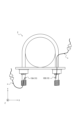
- It is a figure which shows the structure when piping is fixed with a U-bolt.
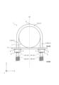
- FIG. 1 is a diagram showing a configuration example of a U-bolt 1 according to the first embodiment of the present disclosure.
- the U-bolt 1 is made of metal such as steel. As shown in FIG. 1 , the U-bolt 1 includes a body portion 11 including shaft portions 111A and 111B and a bridge portion 112, and a threaded portion 12. As shown in FIG. A U-bolt 1 is a U-bolt that fastens a fastener 7 using a nut 4 .
- the shaft portion 111A and the shaft portion 111B are aligned in the first direction and extend in a direction orthogonal to the first direction.
- the direction in which the shaft portions 111A and 111B are arranged side by side is referred to as the X-axis direction (first direction), and the direction in which the shaft portions 111A and 111B extend.
- a direction perpendicular to the X-axis direction and the Y-axis direction is referred to as a Z-axis direction (third direction).
- the shaft portion 111A and the shaft portion 111B are collectively referred to as a pair of shaft portions 111.
- the axial part 111 As shown in FIG.
- the bridge portion 112 connects one end of each of the pair of shaft portions 111 .
- the bridge portion 112 is symmetrical with respect to a virtual straight line OY (hereinafter referred to as “virtual line OY”) extending in the Y-axis direction including the U-shaped vertex O formed by the U-bolt 1 .
- the bridge portion 112 is provided at one end of each of the pair of shaft portions 111 and has a shape bent in a semicircular shape. Since the bridge portion 112 configured in this manner is provided at one end of the pair of shaft portions as described above, the U-bolt 1 forms a U-shape as a whole.
- the threaded portion 12 has a threaded structure.
- Each of the pair of shafts has one threaded portion (threaded portion 121 on the vertex side) and one or more threaded portions (threaded portion 122 on the tip side) on the tip side.
- one threaded portion 122 is provided on the distal end side.
- a fastener 7 such as a pipe is placed inside the U-shaped U-bolt 1 (the space surrounded by the pair of shaft portions 111 and the bridge portion 112).
- the shaft portion 111A and the shaft portion are inserted into the pair of through-holes 5 provided in the fastening object 8 such as support hardware from one surface side of the fastening object 8, respectively.
- 111B is inserted.
- a threaded portion 12 protruding from the other side of the fastened object 8 is tightened by a nut 4 .
- the nut 4 has a screw thread to be screwed with the screw thread of the threaded portion 12 .
- the fastening object 7 is sandwiched between the U-bolt 1 and the fastening object 8 and fixed.
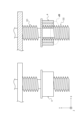
- 2A and 2B show a structure that prevents the nut 4 from falling by providing two threads 12 of the U-bolt 1 on one side.
- the nut 4 falls means that the nut 4 is completely removed from the shaft portion 111 .
- 2A shows a cross section of the threaded portion 12 and the nut 4 when the nut 4 is tightened
- FIG. 2B shows a cross section of the nut 4 when the nut 4 is lowered.
- “descent of the nut 4" means that the nut 4 is detached from the threaded portion 121 on the vertex side and caught by the threads of the threaded portion 122 on the tip side.
- the threaded portion 12 of the U-bolt 1 By providing the threaded portion 12 of the U-bolt 1 at two locations on one side, when the nut 4 is loosened, it stops at the boundary portion 123 of the threaded portion, preventing the nut 4 from falling.
- the “thread boundary 123 ” refers to a portion between the apical thread 121 and the distal thread 122 or between a plurality of distal shafts 122 .
- the nut 4 stops descending.
- it is desirable to ensure that the number of turns of the thread is three or more in one threaded portion.
- the threaded portion on the tip side is provided with a thread groove that does not engage with the thread of the nut, and the thread groove that does not screw together is a U-bolt provided on the top side of the threaded portion on the tip side. It is a sectional view.
- the non-threaded thread groove 132 is cut so that only the top surface 142 of the thread is cut and the top 141 of the thread remains.
- FIG. 4A is a cross-sectional view of a U-bolt that coincides with the thread start and end positions of adjacent threads.
- FIG. 4B is a cross-sectional view of a U-bolt in which the thread start and end positions of adjacent threads are offset. As shown in FIG. 4B, the start position and end position of the thread are shifted by the distance between the vertical lines a and b (that is, the start positions of the thread portions 12 adjacent to each other when viewed in the Y-axis direction are offset from each other). and end positions are not consecutive). On the other hand, as shown in FIG.
- FIG. 5 is a cross-sectional view of a U-bolt in which threaded portions are provided at three or more locations on each of a pair of shaft portions.
- FIG. 6 is a cross-sectional view of a U-bolt provided with a thread groove that does not engage with the threads of the nut, and the start and end positions of the threads of adjacent threads are shifted. As shown in FIG.
- the U-bolt 1 has one threaded portion on the top side and one or more threaded portions on the tip side of each of the pair of shaft portions 111 . Therefore, the U-bolt 1 can be prevented from falling due to the loosening of the nut 4 .
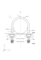
- FIG. 7 is a diagram showing a configuration example of the U-bolt 2 according to the second embodiment of the present disclosure.
- the U-bolt 2 according to this embodiment is made of metal such as steel. As shown in FIG. 7, the U-bolt 2 includes a body portion 11 including shaft portions 111A and 111B, a bridge portion 112, a threaded portion 12, and sensors 15A and 15B.
- the U-bolt 2 according to this embodiment differs from the U-bolt 1 according to the first embodiment in that it further includes a sensor 15A and a sensor 15B.
- the same reference numerals as in the first embodiment are assigned to the same configurations as in the first embodiment, and the description thereof is omitted as appropriate.
- FIG. 8 is a diagram showing a structure in which the sensor is embedded and mounted in a hole drilled in the U-bolt shaft.
- the U-bolt 2 is fixed inside a hole 16 formed in the boundary 123 of the adjacent threaded portions, and the distance to an object located in the X-axis direction (first direction) is fixed.
- a sensor 15 for measuring is further provided.
- a stopper stp may be provided on the outer circumference of the hole 16 to prevent the sensor 15 from dropping out of the hole 16 and falling.
- the stopper stp is provided by welding the same metal material as the metal forming the shaft to the outer circumference of the hole 16 formed in the shaft.
- the sensor 15 can be prevented from falling by filling the inside of the hole 16 with a resin such as an adhesive and fixing the sensor 15 .
- the sensor 15A and the sensor 15B are referred to as the sensor 15 when not distinguished from each other.
- the sensor 15A and the sensor 15B are collectively referred to as a pair of sensors 15. As shown in FIG.
- the sensor 15 By installing the sensor 15, it becomes possible to detect the descent of the nut 4 from the top side.
- the sensor 15 reacts and detects that the nut 4 has descended. It is desirable that the hole 16 be formed at a position closer to the tip side than the center of the boundary 123 of the threaded portion (the position of the dashed line OX). This is to make it easier for the sensor 15 to detect the nut 4 when the nut 4 descends and is caught by the threads of the threaded portion 122 on the tip side and stops descending.
- the sensor 15 may erroneously detect that the nut 4 has fallen. Therefore, as shown in FIG. 7, the sensor 15A and the sensor 15B are embedded in the boundary portion 123 of the threaded portion of both shafts so as to face each other. As a result, the sensors 15A and 15B can determine whether the nut 4 is lowered or whether a foreign object has adhered to the sensor 15 on the other side.
- the sensor 15 is a sensor that measures the distance to an object by irradiating the object with ultrasonic waves, infrared rays, lasers, or the like.
- FIG. 9A is a schematic diagram showing how to power the sensor via a wired cable.
- FIG. 9B is a schematic diagram showing how the sensor is powered from a battery embedded in the stem. Since the sensor 15 requires power supply, a method of supplying power from the outside via a wired cable c shown in FIG. 9A, a method of supplying power from a battery 18 embedded in the shaft portion shown in FIG. 9B, or the like is used to supply power. .
- the diameter of the U-bolt 2 is 10 mm or more. It is preferable that
- the U-bolt 2 further includes a sensor 15 that detects the descent of the nut 4. Therefore, the U-bolt 2 can prevent the nut 4 from falling due to loosening and can detect the descent of the nut 4 .
- FIG. 10 is a block diagram showing a configuration example of a detection device according to the third embodiment.
- the detection device 20 according to the third embodiment includes a master device 30 having a receiving unit 31, a control unit 32, and an alert issuing unit 33, a sensor 15, and a transmitting unit 34. and a U-bolt 3 having .
- the detection device 20 detects the descent of the nut coupled with the U-bolt fastened to the object to be fastened.
- the sensor 15 associated with the U-bolt 3 may be the same as the sensor 15 associated with the second embodiment.
- the detection device 20 may be composed of one parent device 30 and a plurality of U-bolts 3 .
- the same reference numerals as in the second embodiment are assigned to the same configurations as in the second embodiment, and the description thereof is omitted as appropriate.
- the master unit 30 determines whether or not the nut 4 is lowered, and issues an alert when determining that the nut 4 is lowered. do.
- the receiving unit 31 receives the measurement result transmitted from the transmitting unit of the U bolt 3.
- the receiver 31 outputs the transmission result to the controller 32 .
- Transmission of the measurement result from the transmission unit 34 of the U bolt 3 to the reception unit 31 of the base unit 30 may be performed by wired communication, wireless communication such as Wi-Fi, or a combination thereof. .
- the control unit 32 determines whether or not the nut 4 has been lowered based on the measurement result input from the receiving unit 21 . When determining that the nut 4 is lowered, the control section 32 outputs the determination result to the alert issuing section 33 .
- the control unit 32 detects when only one nut 4A is lowered, when only the other nut 4B is lowered, when the nuts 4A and 4B are lowered, and when both sensors 15A and 15B have foreign objects. It is possible to determine each case where measurement is impossible due to adhesion of , and output the determination result to the alert issuing unit 33 . When the control unit 32 determines that the nut 4A or 4B is lowered or that there is no foreign matter adhering to both the sensors 15A and 15B, it continues determination of the measurement result.
- the alert issuing unit 33 When the control unit 32 determines that the nut is descending, the alert issuing unit 33 inputs the determination result that the nut 4 is descending from the control unit 32 and issues an alert.
- the alert issuing unit 33 issues alert A when only one nut 4A is lowered, and alert B when only the other nut 4B is lowered. Also, when the nuts 4A and 4B are lowered, and when the sensors 15A and 15B are stuck with foreign substances and cannot be measured, an alert C is issued.
- the U-bolt 3 transmits the measurement result of the distance to the object measured by the sensor 15 to the parent device 30.
- the transmission unit 34 transmits the measurement results obtained by the sensor 15 to the reception unit 31 of the master device 30.
- FIG. 11 is a flow chart showing an example of a detection method executed by the detection device 20 according to the third embodiment.
- step S10 the sensor 15A of the U-bolt 3 measures the distance from the sensor 15A to the object, and the sensor 15B measures the distance from the sensor 15B to the object.
- step S20 the transmission section 34 of the U bolt 3 transmits the measurement result to the reception section 31 of the parent device 30.
- step S30 the receiving unit 31 of the parent device 30 receives the measurement result and outputs it to the control unit 32.
- step S40 the control unit 32 of the parent device 30 determines whether the nut 4A (the nut on the A side) is lowered. If the nut 4A is not lowered, proceed to S50. If the nut 4A is lowered, proceed to S60.
- step S50 the control unit 32 of the parent device 30 determines whether the nut 4B (the nut on the B side) is lowered. If the nut 4B is lowered, proceed to S80. If the nut 4B is not lowered, the process returns to S10 to continue the measurement.
- step S60 the control unit 32 of the parent device 30 determines whether the nut 4B is lowered. If the nut 4B is not lowered, proceed to S70. If the nut 4B is lowered, proceed to S90.
- the alert issuing unit 33 of the parent device 30 issues an alert A due to the descent of the nut 4A.
- the alert issuing unit 33 of the parent device 30 issues an alert B due to the descent of the nut 4B.
- step S90 the alert issuing unit 33 of the parent device 30 issues an alert C due to the dropping of the nuts 4A and 4B or the adherence of foreign matter to both the sensors 15A and 15B.
- the detection device 20 determines whether the U-bolt 3 including the sensor 15 for detecting the descent of the nut 4 and whether or not the nut 4 is lowered, and issues an alert when the nut 4 is lowered.
- a master device 30 is provided. Therefore, the detection device 20 can notify the worker of the descent of the nut 4 by detecting the descent due to the loosening of the nut 4 and issuing an alert.
Landscapes
- Engineering & Computer Science (AREA)
- General Engineering & Computer Science (AREA)
- Mechanical Engineering (AREA)
- Physics & Mathematics (AREA)
- General Physics & Mathematics (AREA)
- Geophysics And Detection Of Objects (AREA)
- Bridges Or Land Bridges (AREA)
Priority Applications (3)
| Application Number | Priority Date | Filing Date | Title |
|---|---|---|---|
| PCT/JP2021/041972 WO2023084792A1 (ja) | 2021-11-15 | 2021-11-15 | Uボルト、検知装置及び検知方法 |
| JP2023559398A JP7617480B2 (ja) | 2021-11-15 | 2021-11-15 | Uボルト、検知装置及び検知方法 |
| US18/709,472 US20250027768A1 (en) | 2021-11-15 | 2021-11-15 | U-bolt, detection device, and detection method |
Applications Claiming Priority (1)
| Application Number | Priority Date | Filing Date | Title |
|---|---|---|---|
| PCT/JP2021/041972 WO2023084792A1 (ja) | 2021-11-15 | 2021-11-15 | Uボルト、検知装置及び検知方法 |
Publications (1)
| Publication Number | Publication Date |
|---|---|
| WO2023084792A1 true WO2023084792A1 (ja) | 2023-05-19 |
Family
ID=86335532
Family Applications (1)
| Application Number | Title | Priority Date | Filing Date |
|---|---|---|---|
| PCT/JP2021/041972 Ceased WO2023084792A1 (ja) | 2021-11-15 | 2021-11-15 | Uボルト、検知装置及び検知方法 |
Country Status (3)
| Country | Link |
|---|---|
| US (1) | US20250027768A1 (https=) |
| JP (1) | JP7617480B2 (https=) |
| WO (1) | WO2023084792A1 (https=) |
Families Citing this family (2)
| Publication number | Priority date | Publication date | Assignee | Title |
|---|---|---|---|---|
| JP7538444B2 (ja) * | 2021-01-25 | 2024-08-22 | 日本電信電話株式会社 | Uボルト及び施工方法 |
| TWI849572B (zh) * | 2022-11-09 | 2024-07-21 | 財團法人工業技術研究院 | 非接觸式檢測裝置及其檢測方法 |
Citations (5)
| Publication number | Priority date | Publication date | Assignee | Title |
|---|---|---|---|---|
| JPS5746120U (https=) * | 1980-08-30 | 1982-03-13 | ||
| JP2012172695A (ja) * | 2011-02-17 | 2012-09-10 | Tokyo Tekku Wei Kk | ロッド状部材を支持体に対して締結するための締結機構 |
| JP2015219081A (ja) * | 2014-05-16 | 2015-12-07 | 株式会社共和電業 | センサ付きボルト、センサ付きナット、ねじ緩みもしくはねじ離脱検知装置およびねじ緩みもしくはねじ離脱監視システム |
| KR102040104B1 (ko) * | 2019-01-16 | 2019-11-05 | 임세춘 | 너트 이탈 방지 볼트 |
| JP2019215272A (ja) * | 2018-06-13 | 2019-12-19 | 株式会社NejiLaw | 嵌合構造 |
Family Cites Families (1)
| Publication number | Priority date | Publication date | Assignee | Title |
|---|---|---|---|---|
| US6715979B1 (en) * | 2003-02-12 | 2004-04-06 | Home Depot U.S.A., Inc. | Adjustable lift dolly |
-
2021
- 2021-11-15 US US18/709,472 patent/US20250027768A1/en active Pending
- 2021-11-15 WO PCT/JP2021/041972 patent/WO2023084792A1/ja not_active Ceased
- 2021-11-15 JP JP2023559398A patent/JP7617480B2/ja active Active
Patent Citations (5)
| Publication number | Priority date | Publication date | Assignee | Title |
|---|---|---|---|---|
| JPS5746120U (https=) * | 1980-08-30 | 1982-03-13 | ||
| JP2012172695A (ja) * | 2011-02-17 | 2012-09-10 | Tokyo Tekku Wei Kk | ロッド状部材を支持体に対して締結するための締結機構 |
| JP2015219081A (ja) * | 2014-05-16 | 2015-12-07 | 株式会社共和電業 | センサ付きボルト、センサ付きナット、ねじ緩みもしくはねじ離脱検知装置およびねじ緩みもしくはねじ離脱監視システム |
| JP2019215272A (ja) * | 2018-06-13 | 2019-12-19 | 株式会社NejiLaw | 嵌合構造 |
| KR102040104B1 (ko) * | 2019-01-16 | 2019-11-05 | 임세춘 | 너트 이탈 방지 볼트 |
Also Published As
| Publication number | Publication date |
|---|---|
| US20250027768A1 (en) | 2025-01-23 |
| JP7617480B2 (ja) | 2025-01-20 |
| JPWO2023084792A1 (https=) | 2023-05-19 |
Similar Documents
| Publication | Publication Date | Title |
|---|---|---|
| WO2023084792A1 (ja) | Uボルト、検知装置及び検知方法 | |
| JP5805347B2 (ja) | センサ式連結要素および製造方法 | |
| AU2023201275B2 (en) | System and tool for wireless retrieval of measured component data | |
| CN1826507B (zh) | 用于光纤布拉格光栅传感器的固定器 | |
| CN102141015B (zh) | 将负载传感器附接到转子叶片的表面的方法和转子叶片 | |
| ES2668803T3 (es) | Procedimiento para la supervisión o verificación de la tensión previa de bulones roscados en uniones atornilladas sometidas a solicitaciones dinámicas | |
| CN105960582A (zh) | 智能螺栓及其系统 | |
| CN104697673A (zh) | 锚杆轴力测试方法 | |
| JP4316283B2 (ja) | 緊張材の定着部構造及び緊張材の応力測定方法 | |
| JP2005091086A (ja) | ボルト軸力検出器、ボルト軸力検出器付きボルト、ボルトおよびボルト締付け管理方法 | |
| CN209978964U (zh) | 脚手架监控组件及脚手架监控系统 | |
| CN104697674A (zh) | 锚杆受力测试装置及其应用方法 | |
| CN220437464U (zh) | 适应承插型盘扣支架立杆的轴力与倾斜复合传感器及测量系统 | |
| CN105164430B (zh) | 用于监控结构构件中的粘接机构的指示螺栓 | |
| WO2000022306A1 (en) | Monitoring tension of threaded fasteners | |
| EP3667281A1 (en) | Failure monitoring system for a machine element for detecting crack propagation | |
| KR101634443B1 (ko) | 볼트의 축력 감지장치 | |
| CN101788358B (zh) | 便携式电梯曳引机制动性能检测装置 | |
| CN210005147U (zh) | 应力监测螺栓 | |
| CN120721276B (zh) | 一种基于视觉感知的atp系统的速度传感器用螺栓预紧力监测和松动预警方法 | |
| CN209512823U (zh) | 一种可重复使用的螺栓载荷传感器 | |
| CN106441660A (zh) | 一种锚杆垫板受力测量装置 | |
| JP2023085656A (ja) | ロックボルト用荷重センサ | |
| CN223524797U (zh) | 一种应力传感器固定装置及应力传感器装置 | |
| Shirakawa et al. | Evaluation of bolt strength characteristics in bolted joints using an optical fiber sensor system |
Legal Events
| Date | Code | Title | Description |
|---|---|---|---|
| 121 | Ep: the epo has been informed by wipo that ep was designated in this application |
Ref document number: 21964145 Country of ref document: EP Kind code of ref document: A1 |
|
| WWE | Wipo information: entry into national phase |
Ref document number: 2023559398 Country of ref document: JP |
|
| WWE | Wipo information: entry into national phase |
Ref document number: 18709472 Country of ref document: US |
|
| 122 | Ep: pct application non-entry in european phase |
Ref document number: 21964145 Country of ref document: EP Kind code of ref document: A1 |