WO2023074546A1 - 車両用灯具 - Google Patents
車両用灯具 Download PDFInfo
- Publication number
- WO2023074546A1 WO2023074546A1 PCT/JP2022/039229 JP2022039229W WO2023074546A1 WO 2023074546 A1 WO2023074546 A1 WO 2023074546A1 JP 2022039229 W JP2022039229 W JP 2022039229W WO 2023074546 A1 WO2023074546 A1 WO 2023074546A1
- Authority
- WO
- WIPO (PCT)
- Prior art keywords
- light
- distribution pattern
- light distribution
- incident
- light source
- Prior art date
- Legal status (The legal status is an assumption and is not a legal conclusion. Google has not performed a legal analysis and makes no representation as to the accuracy of the status listed.)
- Ceased
Links
Images






Classifications
-
- F—MECHANICAL ENGINEERING; LIGHTING; HEATING; WEAPONS; BLASTING
- F21—LIGHTING
- F21S—NON-PORTABLE LIGHTING DEVICES; SYSTEMS THEREOF; VEHICLE LIGHTING DEVICES SPECIALLY ADAPTED FOR VEHICLE EXTERIORS
- F21S41/00—Illuminating devices specially adapted for vehicle exteriors, e.g. headlamps
- F21S41/10—Illuminating devices specially adapted for vehicle exteriors, e.g. headlamps characterised by the light source
- F21S41/14—Illuminating devices specially adapted for vehicle exteriors, e.g. headlamps characterised by the light source characterised by the type of light source
- F21S41/141—Light emitting diodes [LED]
- F21S41/143—Light emitting diodes [LED] the main emission direction of the LED being parallel to the optical axis of the illuminating device
-
- F—MECHANICAL ENGINEERING; LIGHTING; HEATING; WEAPONS; BLASTING
- F21—LIGHTING
- F21S—NON-PORTABLE LIGHTING DEVICES; SYSTEMS THEREOF; VEHICLE LIGHTING DEVICES SPECIALLY ADAPTED FOR VEHICLE EXTERIORS
- F21S41/00—Illuminating devices specially adapted for vehicle exteriors, e.g. headlamps
- F21S41/10—Illuminating devices specially adapted for vehicle exteriors, e.g. headlamps characterised by the light source
- F21S41/14—Illuminating devices specially adapted for vehicle exteriors, e.g. headlamps characterised by the light source characterised by the type of light source
- F21S41/141—Light emitting diodes [LED]
- F21S41/151—Light emitting diodes [LED] arranged in one or more lines
- F21S41/153—Light emitting diodes [LED] arranged in one or more lines arranged in a matrix
-
- F—MECHANICAL ENGINEERING; LIGHTING; HEATING; WEAPONS; BLASTING
- F21—LIGHTING
- F21S—NON-PORTABLE LIGHTING DEVICES; SYSTEMS THEREOF; VEHICLE LIGHTING DEVICES SPECIALLY ADAPTED FOR VEHICLE EXTERIORS
- F21S41/00—Illuminating devices specially adapted for vehicle exteriors, e.g. headlamps
- F21S41/20—Illuminating devices specially adapted for vehicle exteriors, e.g. headlamps characterised by refractors, transparent cover plates, light guides or filters
- F21S41/24—Light guides
-
- F—MECHANICAL ENGINEERING; LIGHTING; HEATING; WEAPONS; BLASTING
- F21—LIGHTING
- F21S—NON-PORTABLE LIGHTING DEVICES; SYSTEMS THEREOF; VEHICLE LIGHTING DEVICES SPECIALLY ADAPTED FOR VEHICLE EXTERIORS
- F21S41/00—Illuminating devices specially adapted for vehicle exteriors, e.g. headlamps
- F21S41/20—Illuminating devices specially adapted for vehicle exteriors, e.g. headlamps characterised by refractors, transparent cover plates, light guides or filters
- F21S41/25—Projection lenses
-
- F—MECHANICAL ENGINEERING; LIGHTING; HEATING; WEAPONS; BLASTING
- F21—LIGHTING
- F21S—NON-PORTABLE LIGHTING DEVICES; SYSTEMS THEREOF; VEHICLE LIGHTING DEVICES SPECIALLY ADAPTED FOR VEHICLE EXTERIORS
- F21S41/00—Illuminating devices specially adapted for vehicle exteriors, e.g. headlamps
- F21S41/40—Illuminating devices specially adapted for vehicle exteriors, e.g. headlamps characterised by screens, non-reflecting members, light-shielding members or fixed shades
-
- F—MECHANICAL ENGINEERING; LIGHTING; HEATING; WEAPONS; BLASTING
- F21—LIGHTING
- F21S—NON-PORTABLE LIGHTING DEVICES; SYSTEMS THEREOF; VEHICLE LIGHTING DEVICES SPECIALLY ADAPTED FOR VEHICLE EXTERIORS
- F21S41/00—Illuminating devices specially adapted for vehicle exteriors, e.g. headlamps
- F21S41/60—Illuminating devices specially adapted for vehicle exteriors, e.g. headlamps characterised by a variable light distribution
- F21S41/65—Illuminating devices specially adapted for vehicle exteriors, e.g. headlamps characterised by a variable light distribution by acting on light sources
- F21S41/663—Illuminating devices specially adapted for vehicle exteriors, e.g. headlamps characterised by a variable light distribution by acting on light sources by switching light sources
-
- F—MECHANICAL ENGINEERING; LIGHTING; HEATING; WEAPONS; BLASTING
- F21—LIGHTING
- F21W—INDEXING SCHEME ASSOCIATED WITH SUBCLASSES F21K, F21L, F21S and F21V, RELATING TO USES OR APPLICATIONS OF LIGHTING DEVICES OR SYSTEMS
- F21W2102/00—Exterior vehicle lighting devices for illuminating purposes
- F21W2102/10—Arrangement or contour of the emitted light
- F21W2102/13—Arrangement or contour of the emitted light for high-beam region or low-beam region
- F21W2102/135—Arrangement or contour of the emitted light for high-beam region or low-beam region the light having cut-off lines, i.e. clear borderlines between emitted regions and dark regions
- F21W2102/155—Arrangement or contour of the emitted light for high-beam region or low-beam region the light having cut-off lines, i.e. clear borderlines between emitted regions and dark regions having inclined and horizontal cutoff lines
-
- F—MECHANICAL ENGINEERING; LIGHTING; HEATING; WEAPONS; BLASTING
- F21—LIGHTING
- F21W—INDEXING SCHEME ASSOCIATED WITH SUBCLASSES F21K, F21L, F21S and F21V, RELATING TO USES OR APPLICATIONS OF LIGHTING DEVICES OR SYSTEMS
- F21W2102/00—Exterior vehicle lighting devices for illuminating purposes
- F21W2102/20—Illuminance distribution within the emitted light
Definitions
- the present invention relates to a vehicle lamp equipped with a projection lens.
- Japanese Patent Laid-Open Publication No. 2002-100000 discloses a light guide body configured to guide light emitted from a light source between a light source and a projection lens so as to enter the projection lens as a configuration of such a vehicle lamp. is described.
- the vehicular lamp described in this "Patent Document 1" has a first light source for forming a light distribution pattern for low beam as its light source, and forms a light distribution pattern for high beam by simultaneous lighting of the first light source. and a first light guide for guiding the light emitted from the first light source and a light guide for guiding the light emitted from the second light source. and a second light guide for.
- the second light source is composed of a plurality of second light emitting elements arranged in a horizontal direction below the first light source.
- a vehicular lamp having a configuration in which two light guides are provided with a plurality of second incident portions into which light emitted from each of the plurality of second light emitting elements is incident is described.
- the high beam light distribution pattern As in the vehicular lamp described in the above-mentioned "Patent Document 1", if it is configured to have a plurality of second light emitting elements arranged side by side in the left and right direction as the second light source, the high beam light distribution pattern It is possible to form the additional light distribution pattern added to the low beam light distribution pattern as a horizontally elongated light distribution pattern.
- the additional light distribution pattern as a light distribution pattern with less unevenness in light distribution. difficult to form.
- the present invention has been made in view of such circumstances, and provides a vehicle lamp that is configured to irradiate light emitted from a light source through a projection lens toward the front of the lamp at a low cost. Accordingly, it is an object of the present invention to provide a vehicle lamp capable of forming a high-beam light distribution pattern as a light distribution pattern with little light distribution unevenness.
- the present invention aims to achieve the above object by devising the configuration of the light guide disposed between the light source and the projection lens.
- the vehicle lamp according to the present invention is A vehicular lamp comprising a light source and a projection lens, and configured to emit light emitted from the light source toward the front of the lamp via the projection lens,
- a light guide body configured to guide the light emitted from the light source to enter the projection lens is arranged between the light source and the projection lens,
- the light source includes a first light source for forming a low beam light distribution pattern and a second light source for forming a high beam light distribution pattern by simultaneous lighting with the first light source
- the second light source is composed of a plurality of second light emitting elements arranged in a horizontal direction below the first light source
- the light guide includes a first incident portion for incident light emitted from the first light source and a plurality of second incident portions for incident light emitted from each of the plurality of second light emitting elements,
- the light guide includes a first emission surface for emitting light for the low-beam light distribution pattern, and an additional light distribution added to the low-beam light distribution pattern when forming the high
- the second incidence section includes a front incidence surface on which light emitted from the second light emitting element is incident as light directed toward the second emission surface, and an emission from the second light emitting element around the front incidence surface.
- the specific configuration of the "first light source” is not particularly limited.
- the specific arrangement and the number of arrangement are particularly It is not limited.
- the side incident surface is formed around the front incident surface so that the emitted light from the second light emitting element is incident as light directed in a direction away from the front incident surface
- the specific arrangement, surface shape, and the like are not particularly limited, and the front incident surface need not necessarily be formed to surround the entire circumference.
- the above-mentioned "second incident part” forms a diffusion area of the additional light distribution pattern by reflected light from the reflection area on the left-right direction end side of the total reflection surface, and also forms a diffusion area of the additional light distribution pattern, and If the center area of the additional light distribution pattern is formed by the reflected light from the reflection area, the specific irradiation range and the total area of the reflected light from the reflection area on the left-right direction end side of the total reflection surface.
- a specific irradiation range of the reflected light from the reflection area on the center side in the left-right direction on the reflection surface is not particularly limited.
- the vehicle lamp according to the present invention is configured to irradiate the light emitted from the light source toward the front of the lamp via the projection lens. is arranged to guide the light to enter the projection lens, the light distribution pattern having a desired shape is formed by controlling the incident light to the projection lens with this light guide. can be easily done.
- the vehicle lamp according to the present invention includes, as its light sources, a first light source for forming a light distribution pattern for low beam and a second light source for forming a light distribution pattern for high beam by simultaneous lighting of the first light source.
- the second light source is composed of a plurality of second light emitting elements arranged in a horizontal direction below the first light source, and the light guide body is formed with a plurality of second incident portions for receiving light emitted from each of the plurality of second light-emitting elements, so that when forming a high-beam light distribution pattern, the second incident portion is added to the low-beam light distribution pattern. It becomes possible to easily form the additional light distribution pattern to be formed as a laterally elongated light distribution pattern.
- the second incidence section includes a front incidence surface on which light emitted from the second light emitting element is incident as light directed toward the second emission surface, and light emitted from the second light emitting element around the front incidence surface. is incident as light directed away from the front incident surface, and a total reflection surface for totally reflecting emitted light from the second light emitting element incident from the side incident surface toward the second emission surface. and , the light emitted from the second light emitting element can be efficiently used.
- the second incident portion positioned at the end in the left-right direction among the plurality of second incident portions forms an additional light distribution pattern by reflected light from the reflection area on the end side in the left-right direction on the total reflection surface.
- the diffusion area is formed, and the center area of the additional light distribution pattern is formed by the reflected light from the reflection area on the center side in the horizontal direction of the total reflection surface. can be obtained.
- the additional light distribution pattern can be formed as a light distribution pattern with little light distribution unevenness in which a plurality of light distribution patterns are superimposed on each other.
- the light distribution pattern can also be formed as a light distribution pattern with little light distribution unevenness.
- a light distribution pattern for a high beam is arranged by an inexpensive configuration of the lamp. A light distribution pattern with little light unevenness can be formed.
- the total reflection surface of the second incident portion located at the end in the left-right direction has a larger horizontal diffusion angle of the reflected light than the total reflection surface of the second incident portion adjacent to the center side in the left-right direction.
- the additional light distribution pattern can be formed as a light distribution pattern in which the brightness gradually decreases from the center region in the left-right direction to the end region, thereby improving the visibility of the high-beam light distribution pattern. It can be formed as a light distribution pattern.
- the front incidence surface of the second incidence section located at the end in the left-right direction is formed so as to deflect the emitted light from the second light-emitting element toward the center in the left-right direction.
- the additional light distribution pattern as a light distribution pattern in which the brightness gradually decreases from the center region in the left-right direction to the end region, thereby visually recognizing the high-beam light distribution pattern. It becomes possible to more easily form a light distribution pattern having excellent properties.
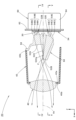
- FIG. 1 is a side cross-sectional view showing a vehicle lamp according to an embodiment of the present invention; View from the direction of arrow II in Fig. 1
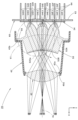
- FIG. 2 is a side cross-sectional view showing the lighting unit of the vehicle lighting as a single item.
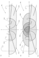
- IV-IV line sectional view of Fig. 3 VV line sectional view of FIG. Detailed view of VI in Fig. 5
- FIG. 6 is a view similar to FIG. 5 showing a modification of the above embodiment;
- FIG. 1 is a side sectional view showing a vehicle lamp 10 according to one embodiment of the present invention.
- 2 is a view taken in the direction of arrow II in FIG. 1.
- FIG. 1 is a side sectional view showing a vehicle lamp 10 according to one embodiment of the present invention.
- 2 is a view taken in the direction of arrow II in FIG. 1.
- FIG. 1 is a side sectional view showing a vehicle lamp 10 according to one embodiment of the present invention. 2 is a view taken in the direction of arrow II in FIG. 1.
- the direction indicated by X is the "front of the lamp”
- the direction indicated by Y is the “left direction” ("right direction” when viewed from the front of the lamp) orthogonal to the "front of the lamp”
- the direction indicated by Z. is the "upward direction”. The same applies to figures other than these.
- a vehicle lamp 10 is a headlamp provided at the front end of a vehicle, and has a configuration in which a lamp unit 20 is accommodated in a lamp chamber formed by a lamp body 12 and a translucent cover 14 . It has become.
- FIG. 3 is a side sectional view showing the lighting unit 20 alone.
- 4 is a sectional view taken along line IV-IV of FIG. 3
- FIG. 5 is a sectional view taken along line VV of FIG.
- the lamp unit 20 is a projector-type lamp unit, and irradiates light emitted from a light source 30 through a projection lens 40 toward the front of the lamp, thereby producing a low-beam distribution. It is configured to form a light pattern and a high beam light distribution pattern (which will be described later).
- the projection lens 40 has an optical axis Ax extending in the longitudinal direction of the lamp, and forms the light distribution pattern by reversely projecting a projection image formed on the rear focal plane.
- a light guide 50 configured to guide the light emitted from the light source 30 to enter the projection lens 40 is arranged. there is The projection image is formed on the light guide 50 .
- the projection lens 40 is a biconvex aspherical lens having an outer peripheral flange portion 40a, and is made of a transparent and colorless resin member.
- the projection lens 40 has a lens shape in which the upper and lower portions of a circular shape are horizontally cut off when viewed from the front of the lamp, and is supported by a lens holder 42 at its outer peripheral flange portion 40a.
- the lens holder 42 is a cylindrical member extending in the longitudinal direction of the lamp, and has a lens supporting portion 42a for supporting the projection lens 40 at its front end.
- the light source 30 is composed of three first light emitting elements 32A, 32B, 32C and three second light emitting elements 32D, 32E, 32F mounted on a common substrate .
- Each of the first and second light emitting elements 32A to 32F is a white light emitting diode having a rectangular (for example, square) light emitting surface, and is arranged with the light emitting surface facing forward of the lamp.
- the three first light emitting elements 32A to 32C are configured as first light sources that are lit when forming the low beam light distribution pattern, and the three second light emitting elements 32D to 32F form the high beam light distribution pattern. It is configured as a second light source that is additionally lit when the light source is turned on.
- the three first light emitting elements 32A to 32C are arranged at a position directly above the optical axis Ax of the projection lens 40 and at equally spaced positions on both left and right sides thereof, and the three second light emitting elements 32D to 32F , and are arranged at a position just below the optical axis Ax and at positions equally spaced on both left and right sides thereof. At that time, the interval between the three second light emitting elements 32D to 32F is set to a smaller value than the interval between the three first light emitting elements 32A to 32C.
- the substrate 34 is supported by a metal heat sink 60 while being arranged so as to extend along a vertical plane perpendicular to the optical axis Ax of the projection lens 40 .
- the heat sink 60 includes a main body portion 62 extending along a vertical plane orthogonal to the optical axis Ax of the projection lens 40, and a plurality of radiation fins 64 extending along the vertical plane from the main body portion 62 toward the rear of the lamp. It is supported by the lens holder 42 in a state in which the body portion 62 is in surface contact with the substrate 34 .
- the light guide 50 is composed of a colorless and transparent resin member.
- the light guide 50 has a first emission surface 52A for emitting light for the low-beam light distribution pattern and an additional light distribution added to the low-beam light distribution pattern when forming the high-beam light distribution pattern. It has a second emission surface 52B for emitting pattern light, and an upward reflection surface 52C formed to connect the first emission surface 52A and the second emission surface 52B.
- the first emission surface 52A constitutes the front upper portion of the light guide 50.
- the first emission surface 52A is formed in a concave curved surface at a position a certain amount away from the rear focal plane of the projection lens 30 toward the rear side of the lamp, and has a substantially horizontally long rectangular outer shape when viewed from the front of the lamp. are doing.
- the upward reflective surface 52C extends from the lower edge of the first emission surface 52A toward the front of the lamp along the horizontal plane, and is formed with left and right steps when viewed from the front of the lamp.
- the upward reflecting surface 52C is formed by subjecting the surface of the light guide 50 to mirror finishing (for example, aluminum vapor deposition).
- a front edge 52Ca of the upward reflecting surface 52C is formed so as to pass through the vicinity of the rear focal point F of the projection lens 30 and extend curvedly toward the front side of the lamp in both left and right directions.
- the second emission surface 52B constitutes the lower front surface of the light guide 50.
- the second emission surface 52B is formed to extend downward from the front edge 52Ca of the upward reflecting surface 52C with a slight inclination toward the front side of the lamp, and has a substantially oblong rectangular outer shape when viewed from the front of the lamp. are doing.
- the light guide 50 includes three first incident portions 54A, 54B, and 54C for incident light emitted from each of the three first light emitting elements 32A, 32B, and 32C, It is provided with three second incident portions 54D, 54E, 54F for receiving light emitted from each of the three second light emitting elements 32D, 32E, 32F.
- the three first incident portions 54A to 54C are formed to be positioned on the front side of the lamp with respect to each of the three first light emitting elements 32A to 32C and on the rear side of the lamp with respect to the first emission surface 52A. ing. In addition, the three second incident portions 54D to 54F are positioned on the front side of the lamp with respect to each of the three second light emitting elements 32D to 32F and on the rear side of the lamp with respect to the second emission surface 52B. formed.
- the light from the first light emitting element 32B that has entered the light guide 50 from the first incident portion 54B positioned directly above the optical axis Ax is emitted from the first emission surface 52A and then directly Alternatively, the light is specularly reflected by the upward reflecting surface 52C, enters the projection lens 30, and is emitted from the projection lens 30 toward the front of the lamp as substantially downward light.
- the light from the second light emitting element 32E that enters the light guide 50 from the second incident portion 54E positioned directly below the optical axis Ax is directly reflected or totally reflected by the upward reflecting surface 52C, and is reflected on the second emitting surface 52E.
- the light is emitted from the second emission surface 52B toward the projection lens 30, and is irradiated from the projection lens 30 toward the front of the lamp as substantially upward light.
- An outer peripheral flange portion 56 extending along a vertical plane perpendicular to the optical axis Ax is formed at a position on the front side of the lamp from the first emission surface 52A on the upper portion and the left and right side portions of the light guide 50 .
- the lens holder 42 is formed with a light guide supporting portion 42 b extending along the outer peripheral flange portion 56 of the light guide 50 .
- the light guide 50 is supported by the lens holder 42 with its outer peripheral flange portion 56 in contact with the rear surface of the light guide supporting portion 42b of the lens holder 42 and positioned.
- the three first incident portions 54A to 54C receive the light emitted from each of the three first light emitting elements 32A to 32C, directly or totally reflect the light, and then 52A.
- each of the first incident portions 54A, 54B, and 54C has front incident surfaces 54A1 and 54B1 on which light emitted from the first light emitting elements 32A, 32B, and 32C is incident as light directed toward the first emission surface 52A. , 54C1, and light emitted from the respective first light emitting elements 32A, 32B, and 32C around the front entrance surfaces 54A1, 54B1, and 54C1 as light directed away from the front entrance surfaces 54A1, 54B1, and 54C1.
- Light emitted from the side incident surfaces 54A2, 54B2, 54C2 and the respective first light emitting elements 32A, 32B, 32C incident from the side incident surfaces 54A2, 54B2, 54C2 is totally reflected toward the first emitting surface 52A. Total reflection surfaces 54A3, 54B3 and 54C3 are provided.
- the three first incident portions 54A to 54C are configured to guide the emitted light from each of the three first light emitting elements 32A to 32C to the first emission surface 52A as a bundle of nearly parallel rays. . Furthermore, at that time, the left-right width of the ray bundle reaching the first exit surface 52A from the first entrance portion 54B located directly above the optical axis Ax is the first exit from the first entrance portions 54A and 54C located on both sides thereof.
- the shape of the three first incident portions 54A to 54C is set so that the ray bundle reaching the first exit surface 52A partially overlaps at the position of the rear focal plane of the projection lens 40.
- the three second incident portions 54D to 54F receive the emitted light from each of the three second light emitting elements 32D to 32F, directly or totally reflect the light, and then It is configured to lead to the exit surface 52B.
- each of the second incident portions 54D, 54E, and 54F has front incident surfaces 54D1 and 54E1 on which light emitted from the second light emitting elements 32D, 32E, and 32F is incident as light directed toward the second emission surface 52B.
- 54F1 and light emitted from the second light emitting elements 32D, 32E, and 32F around the front entrance surfaces 54D1, 54E1, and 54F1 is incident as light directed away from the front entrance surfaces 54D1, 54E1, and 54F1.
- Light emitted from the side entrance surfaces 54D2, 54E2, 54F2 and the respective second light emitting elements 32D, 32E, 32F incident from the side entrance surfaces 54D2, 54E2, 54F2 is totally reflected toward the second exit surface 52B. Total reflection surfaces 54D3, 54E3 and 54F3 are provided.
- the three second incident portions 54D to 54F are configured to guide the light emitted from each of the three second light emitting elements 32D to 32F as a bundle of light beams close to parallel light to the second emission surface 52B.
- the left-right width of the ray bundle reaching the second exit surface 52B from the second entrance portion 54E located directly below the optical axis Ax will be the same as that from the second entrance portions 54E and 54G located on both sides of the second exit surface. 52B so that the width is narrower than the lateral width of the bundle of rays reaching 52B, and the three bundles of rays reaching the second exit surface 52B from the three second incident portions 54D to 54F partially overlap each other. 2
- the shapes of the incident portions 54D to 54F are set.
- FIG. 6 is a detailed view of the VI section in FIG.
- the second incident portion 54E positioned directly below the optical axis Ax has a front incident surface 54E1, a side incident surface 54E2, and a total reflection surface 54E3 that are symmetrical with respect to a vertical plane including the optical axis Ax. has the shape of The second incident portion 54E guides the emitted light from the second light emitting element 32E to the second emitting surface 52B as a light beam having a narrow lateral width and somewhat converging toward the front of the lamp. .
- the second incident portion 54D located on the right side has a front incident surface 54D1 that is formed in a convex curved shape greatly inclined from left to right toward the front side of the lamp.
- the emitted light is deflected and incident toward the left oblique front of the lamp (that is, toward the central portion in the left-right direction).
- the total reflection surface 54D3 of the second incident portion 54D located on the right side has a right reflection area 54D3A (that is, the reflection area on the end side in the left-right direction) that is convex and greatly inclined from left to right toward the front side of the lamp.
- the left reflective area 54D3B (that is, the reflective area on the center side in the left-right direction) is formed in a convex curved shape extending from the right to the left at an inclination angle smaller than that of the right reflective area 54D3A.
- the right reflection area 54D3A extends toward the front of the lamp at an inclination angle larger than that of the total reflection surface 54E3 of the second incidence section 54E, and the left reflection area 54D3B extends from the total reflection surface 54E3 of the second incidence section 54E. also extends toward the front of the lamp at a small angle of inclination.
- the second incident portion 54D directs the light emitted from the second light emitting element 32D obliquely forward to the left of the lamp, and has a lateral width that is wider than the emitted light from the second light emitting element 32E that is incident from the second incident portion 54E. It is designed to be guided to the second exit surface 52B as a bundle of rays that are large and somewhat diffuse. At that time, the luminous flux guided from the second incident portion 54D to the second exit surface 52B has a high luminous flux density on the left side, and the left end portion is located on the left side of the optical axis Ax. 2 reaches the output surface 52B.
- the total reflection surface 54F3 of the second incident portion 54F located on the left side has a shape symmetrical to the total reflection surface 54D3 of the second incident portion 54D located on the right side.
- FIG. 7 is a view perspectively showing a light distribution pattern formed on a virtual vertical screen arranged at a position 25 m in front of the vehicle by light emitted from the lamp unit 20 toward the front of the lamp.
- 7(a) is a diagram showing a low beam light distribution pattern PL
- FIG. 7(b) is a diagram showing a high beam light distribution pattern PH.
- the low-beam light distribution pattern PL is a left-handed low-beam light distribution pattern, and has cutoff lines CL1 and CL2 that are uneven on the left and right at the upper edge thereof.
- the cut-off lines CL1 and CL2 extend in the horizontal direction on the left and right sides of the line VV, which passes vertically through the vanishing point HV in the front direction of the lamp.
- the opposite lane side portion is formed as a lower cutoff line CL1
- the own lane side portion on the left side of the VV line is formed as an upper cutoff line CL2 rising from the lower cutoff line CL1 via an inclined portion. formed.
- the elbow point E which is the intersection of the lower cutoff line CL1 and the line VV, is positioned below HV by about 0.5 to 0.6°.
- the low-beam light distribution pattern PL is formed as a composite light distribution pattern of three light distribution patterns P1L, P1C, and P1R.
- the low-beam light distribution pattern PL is formed as a horizontally elongated light distribution pattern in which three light distribution patterns P1L, P1C, and P1R are arranged side by side in the horizontal direction so as to partially overlap each other. .
- Light distribution patterns P1L, P1C, and P1R are formed on the rear focal plane of projection lens 40 by light emitted from first light emitting elements 32A, 32B, and 32C emitted from first emission surface 52A of light guide 50. This is a light distribution pattern formed as an inverted projection image of the projection image.
- the light guide body 50 extends curvedly toward the front side of the lamp in both left and right directions so that the front edge 52Ca of the upward reflecting surface 52C passes through the vicinity of the rear focal point F of the projection lens 40.
- the low-beam light distribution pattern PL has its cutoff lines CL1 and CL2 clearly formed.
- the high-beam light distribution pattern PH is obtained by adding an additional light distribution pattern PA extending above the cutoff lines CL1 and CL2 to the low-beam light distribution pattern PL. ing.
- the additional light distribution pattern PA is formed as a composite light distribution pattern of three light distribution patterns P2L, P2C, and P2R. At this time, the additional light distribution pattern PA is formed as a horizontally long light distribution pattern in which the three light distribution patterns P2L, P2C, and P2R are aligned in the left-right direction and partially overlapped.
- Each of the light distribution patterns P2L, P2C, and P2R is formed as an inverted projection image of the image for projection formed on the second emission surface 52B of the light guide 50 by the emitted light from each of the second light emitting elements 32D, 32E, and 32F. It is a light distribution pattern.
- the upper end position of the projection image is defined by the front edge 42Ca of the upward reflecting surface 42C
- the lower end position of the additional light distribution pattern PA is defined by the cutoff lines CL1 and CL2. . Therefore, the high-beam light distribution pattern PH is formed by connecting the low-beam light distribution pattern PL and the additional light distribution pattern PA without a gap.
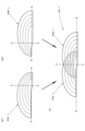
- FIG. 8 is a diagram showing the additional light distribution pattern PA and its establishment.
- the light distribution pattern P2C is formed as a relatively small and bright light distribution pattern centered on HV.
- the second incident portion 54E is formed so as to guide the emitted light from the second light emitting element 32E to the second emitting surface 52B as a light beam having a narrow left-right width toward the front of the lamp and somewhat converging. It is due to
- the multiple curve shown in the light distribution pattern P2C is for showing the luminous intensity distribution of the light distribution pattern P2C, and indicates that the vicinity of HV is the brightest. ing.
- the light distribution pattern P2L is formed as a light distribution pattern extending in the left-right direction so that its right end is located on the right side of the line VV.
- the light distribution pattern P2L is formed as a light distribution pattern whose overall brightness is inferior to that of the light distribution pattern P2C, but the portion near the right end thereof is relatively bright.
- the second incident portion 54D causes the emitted light from the second light emitting element 32D to reach the second emission surface 52B as a light beam having a high light flux density near the left end thereof, and the left end thereof to the optical axis. This is because the light is configured to reach the second exit surface 52B at a position on the left side of Ax.
- the light distribution pattern P2R is formed as a light distribution pattern extending in the left-right direction so that its left end is located on the left side of the VV line.
- the light distribution pattern P2R is formed as a light distribution pattern whose overall brightness is inferior to that of the light distribution pattern P2C, but the portion near the left end thereof is relatively bright.
- the second incidence portion 54F causes the light emitted from the second light emitting element 32F to reach the second emission surface 52B as a light beam having a high luminous flux density near the right end thereof, and the right end to the optical axis. This is because the light is configured to reach the second exit surface 52B at a position on the right side of Ax.
- the additional light distribution pattern PA formed as a combined light distribution pattern of these three light distribution patterns P2L, P2C, and P2R has three The light distribution patterns P2L, P2C, and P2R are formed in an overlapping state, and are formed as a light distribution pattern in which the brightness gradually decreases from the central region toward the left and right ends.
- the vehicular lamp 10 is configured to irradiate the light emitted from the light source 30 toward the front of the lamp via the projection lens 40 .
- the light guide 50 configured to guide the light emitted from the light source 30 to enter the projection lens 40 is arranged.
- the vehicle lamp 10 includes, as the light source 30, three first light emitting elements 32A, 32B, and 32C (first light sources) for forming the low beam light distribution pattern PL, and Three second light emitting elements 32D, 32E, and 32F (second light sources) are provided for forming a high beam light distribution pattern PH by simultaneous lighting, and the three second light emitting elements 32D, 32E, and 32F are , three first light-emitting elements 32A, 32B, and 32C are arranged side by side in the left-right direction below the three first light-emitting elements 32A, 32B, 32C.
- first light sources for forming the low beam light distribution pattern PL
- Three second light emitting elements 32D, 32E, and 32F second light sources
- the three second light emitting elements 32D, 32E, and 32F are arranged side by side in the left-right direction below the three first light-emitting elements 32A, 32B, 32C.
- the addition added to the low-beam light distribution pattern PL when forming the high-beam light distribution pattern PH is formed. It becomes possible to easily form the light distribution pattern PA as a horizontally long light distribution pattern.
- the second incident portions 54D, 54E, and 54F include front incident surfaces 54D1, 54E1, and 54F1 that allow the emitted light from the second light emitting elements 32D, 32E, and 32F to enter the second emitting surface 52B as light directed toward the second emitting surface 52B, and side entrance surfaces 54D2, 54E2, 54F2 around the front entrance surfaces 54D1, 54E1, 54F1, on which light emitted from the second light emitting elements 32D, 32E, 32F is incident as light directed away from the front entrance surfaces.
- total reflection surfaces 54D3, 54E3, 54F3 for totally reflecting the light emitted from the second light emitting elements 32D, 32E, 32F incident from the side incidence surfaces 54D2, 54E2, 54F2 toward the second emission surface 52B. Therefore, the light emitted from the second light emitting elements 32D, 32E, and 32F can be efficiently used.
- the second incident portion 54D located on the right side diffuses the additional light distribution pattern PA by the reflected light from the right reflection region 54D3A (the reflection region on the end side in the left-right direction) of the total reflection surface 54D3.
- the center area of the additional light distribution pattern PA is formed by reflected light from the left reflection area 54D3B (the reflection area on the center side in the left-right direction) of the total reflection surface 54D3, and Since the total reflection surface 54F3 of the second incident portion 54F located on the left side has the same configuration, the following effects can be obtained.
- the additional light distribution pattern PA can be formed as a light distribution pattern with little light distribution unevenness in which the three light distribution patterns P2L, P2C, and P2R are superimposed on each other.
- the high-beam light distribution pattern PH can also be formed as a light distribution pattern with little light distribution unevenness.
- the high beam arrangement can be achieved by the inexpensive lamp configuration.
- the light pattern PH can be formed as a light distribution pattern with little light distribution unevenness.
- the total reflection surface 54D3 of the second incident portion 54D located on the right side is the second incident portion 54D3 located in the center (adjacent to the central portion in the left-right direction). It has a reflecting surface shape formed so that the left-right diffusion angle of the reflected light is larger than that of the total reflection surface 54E3 of the incident portion 54E. have the same reflecting surface shape, the following effects can be obtained.
- the additional light distribution pattern PA can be formed as a light distribution pattern in which the brightness gradually decreases from the center region in the horizontal direction to the end regions, thereby improving the visibility of the high beam light distribution pattern PH. It can be formed as an excellent light distribution pattern.
- the front incident surface 54D1 of the second incident portion 54D located on the right side directs the emitted light from the second light emitting element 32D to the center side in the horizontal direction. Since the front incident surface 54F1 of the second incident portion 54F located on the left side also has a similar incident surface shape, The following effects can be obtained.
- the additional light distribution pattern PA as a light distribution pattern in which the brightness gradually decreases from the center region in the left-right direction to the end regions thereof. can be formed more easily as a light distribution pattern with excellent visibility.
- the first light source is composed of the three light emitting elements 32A, 32B and 32C
- the second light source is also composed of the three light emitting elements 32D, 32E and 32F. It is also possible to set the number of each of the first and second light sources to numbers different from those in the above embodiment.
- the cutoff lines CL1 and CL2 of the low-beam light distribution pattern PL are formed by the front edge 52Ca of the upward reflecting surface 52C.
- the cutoff lines CL1 and CL2 may be formed by the front edge, or the cutoff lines CL1 and CL2 may be formed by a shade formed of a separate member from the light guide 50. is.
- FIG. 9 is a view similar to FIG. 5, showing a lamp unit 120 according to this modified example.
- the basic configuration of this modification is the same as that of the above embodiment, except that the second light source is composed of two second light emitting elements 132G and 132H. and the shape of the light guide 150 is partially different from that of the above embodiment.
- the two second light emitting elements 132G and 132H constituting the second light source are arranged in a symmetrical positional relationship on both left and right sides of the vertical plane including the optical axis Ax. At that time, the distance between the two second light emitting elements 132G and 132H is set to a smaller value than the distance between the right second light emitting element 32D and the left second light emitting element 32F in the above embodiment.
- the light guide body 150 of this modified example has the same basic configuration as that of the above-described embodiment, but two second light-emitting elements 132G and 132H have two second light-emitting elements 132G and 132H on the front side of the lamp. , 154H are formed, which is different from the above embodiment.
- the two second incident portions 154G and 154H are similar to the two second incident portions 54D and 54F in the above-described embodiment, after the emitted light from each of the two second light emitting elements 132G and 132H are incident directly or It is configured to guide the light to the second exit surface 152B after being totally reflected.
- each of the second incident portions 154G and 154H includes a front incident surface 154G1 and 154H1 for allowing light emitted from each of the second light emitting elements 132G and 132H to enter the second emitting surface 152B, and a front incident surface 154G1 and 154H1.
- the two second incident portions 154G and 154H are configured to guide the emitted light from each of the two second light emitting elements 132G and 132H to the second emission surface 152B as a bundle of nearly parallel rays.
- the shapes of the second incident portions 154G and 154H are set such that the two light beams reaching the second exit surface 52B from the two second incident portions 154G and 154H partially overlap each other.
- the front incidence surface 154G1 of the second incidence portion 154G located on the right side is formed in a convex curved surface shape that greatly inclines from the left side to the right side toward the front side of the lamp.
- the configuration is such that incident light is deflected and incident toward the left oblique front of the lamp (that is, toward the central portion in the left-right direction).
- the total reflection surface 154G3 of the second incident portion 154G located on the right side is a convex curved surface in which the right reflection area 154G3A (that is, the reflection area on the end side in the left-right direction) is greatly inclined from left to right toward the front side of the lamp.
- the left reflective area 154G3B (that is, the reflective area on the center side in the left-right direction) is formed in a convex curved shape extending from the right to the left at an inclination angle smaller than that of the right reflective area 154G3A.
- the second incident portion 154G guides the emitted light from the second light emitting element 32D to the second emission surface 152B as a slightly diffused ray bundle.
- the luminous flux guided from the second incident portion 154G to the second exit surface 152B has a high luminous flux density on the left side, and the left end portion is located on the left side of the optical axis Ax. 2 reaches the output surface 152B.
- the total reflection surface 154H3 of the second incident portion 154H located on the left side has a shape symmetrical to the total reflection surface 154G3 of the second incident portion 154G located on the right side.
- the configurations of the first emission surface 152A, the second emission surface 152B, the upward reflecting surface 152C, and the front edge 152Ca thereof are the same as in the above embodiment.
- FIG. 10 is a diagram showing an additional light distribution pattern PA-1 formed by the light emitted from the lamp unit 120 according to this modified example and its formation.
- the additional light distribution pattern PA-1 is formed as a combined light distribution pattern of two light distribution patterns P2L-1 and P2R-1.
- Each of the light distribution patterns P2L-1 and P2R-1 is formed as an inverted projection image of the image for projection formed on the second emission surface 152B of the light guide 150 by the emitted light from each of the second light emitting elements 132G and 132H. It is a light distribution pattern.
- the light distribution pattern P2L-1 is formed as a light distribution pattern extending in the left-right direction so that its right end is located on the right side of the VV line. Similar to the light distribution pattern P2L of the above-described embodiment, this light distribution pattern P2L-1 is formed as a light distribution pattern in which the portion near the right end thereof is relatively bright. is also formed in a state of being displaced to the right.
- the second light emitting element 132G and the second incident part 154G are arranged closer to the optical axis Ax than the second light emitting element 32D and the second incident part 54D of the above embodiment, and the second incident part 154G However, this is because the light emitted from the second light emitting element 132G is configured to reach the second emission surface 152B as a light beam having a high light flux density near the left end.
- the light distribution pattern P2R-1 is formed as a light distribution pattern extending in the left-right direction so that its left end is located on the left side of the line VV. Similar to the light distribution pattern P2R of the above-described embodiment, this light distribution pattern P2R-1 is formed as a light distribution pattern in which the left end portion thereof is relatively brighter than the light distribution pattern P2R of the above-described embodiment. is also displaced to the left.
- the second light emitting element 132H and the second incident portion 154H are arranged closer to the optical axis Ax than the second light emitting element 32F and the second incident portion 54F of the above embodiment, and the second incident portion 154H However, this is because the light emitted from the second light emitting element 132H is configured to reach the second emission surface 152B as a light beam having a high light flux density near the left end.
- an additional light distribution pattern PA-1 formed as a combined light distribution pattern of these two light distribution patterns P2L-1 and P2R-1 has a center position near line VV.
- Two light distribution patterns P2L, P2C, and P2R are formed in an overlapping state in the area, and the light distribution pattern is formed such that the brightness gradually decreases from the center area toward the left and right ends.
- the second light source is composed of the two second light emitting elements 132G and 132H
- the additional light distribution pattern PA-1 is partially overlapped with the two light distribution patterns P2L-1 and P2R-1. It is possible to form a light distribution pattern with little light distribution unevenness. As a result, the light distribution pattern for high beam can also be formed as a light distribution pattern with less light distribution unevenness, and this can be realized with a lamp structure that is even cheaper than in the case of the above embodiment.
Landscapes
- Engineering & Computer Science (AREA)
- General Engineering & Computer Science (AREA)
- Physics & Mathematics (AREA)
- Microelectronics & Electronic Packaging (AREA)
- Optics & Photonics (AREA)
- Mathematical Physics (AREA)
- Non-Portable Lighting Devices Or Systems Thereof (AREA)
Abstract
光源からの出射光を投影レンズを介して灯具前方へ向けて照射するように構成された車両用灯具において、安価な灯具構成により、ハイビーム用配光パターンを配光ムラの少ない配光パターンとして形成可能とする。3つの第2発光素子(32D、32E、32F)を左右方向に並んだ状態で配置し、これらと投影レンズ(40)との間に配置された導光体(50)に3つの第2入射部(54D、54E、54F)を形成する。これによりハイビーム用配光パターン用の付加配光パターンを横長の配光パターンとして形成可能とする。その上で、右側の第2入射部(54D)は、その全反射面(54D3)の右側反射領域からの反射光によって付加配光パターンの拡散領域を形成するとともに左側反射領域からの反射光によって中心領域を形成するように構成し、左側の第2入射部(54F)も同様の構成とする。これにより数少ない第2発光素子であっても付加配光パターンの配光ムラを抑える。
Description
本願発明は、投影レンズを備えた車両用灯具に関するものである。
従来より、光源からの出射光を、投影レンズを介して灯具前方へ向けて照射するように構成された車両用灯具が知られている。
「特許文献1」には、このような車両用灯具の構成として、光源と投影レンズとの間に、光源からの出射光を導光して投影レンズに入射させるように構成された導光体が配置されたものが記載されている。
この「特許文献1」に記載された車両用灯具は、その光源として、ロービーム用配光パターンを形成するための第1光源と、この第1光源との同時点灯によってハイビーム用配光パターンを形成するための第2光源とを備えており、また、その導光体として、第1光源からの出射光を導光するための第1導光体と、第2光源からの出射光を導光するための第2導光体とを備えている。
さらに、この「特許文献1」の図6には、第2光源が、第1光源よりも下方側において左右方向に並んだ状態で配置された複数の第2発光素子で構成されるとともに、第2導光体が、複数の第2発光素子の各々からの出射光を入射させる複数の第2入射部を備えた構成を有する車両用灯具が記載されている。
上記「特許文献1」に記載された車両用灯具のように、第2光源として左右方向に並んだ状態で配置された複数の第2発光素子を備えた構成とすれば、ハイビーム用配光パターンを形成する際にロービーム用配光パターンに対して付加される付加配光パターンを、横長の配光パターンとして形成することが可能となる。
しかしながら、この付加配光パターンを配光ムラのない配光パターンとして形成するためには、第2発光素子を数多く配置することが必要となり、このため車両用灯具を安価に構成することが困難となってしまう。
一方、第2発光素子の数を減らすと、付加配光パターンを配光ムラの少ない配光パターンとして形成することが困難となり、このためハイビーム用配光パターンも配光ムラの少ない配光パターンとして形成することが困難となってしまう。
本願発明は、このような事情に鑑みてなされたものであって、光源からの出射光を投影レンズを介して灯具前方へ向けて照射するように構成された車両用灯具において、安価な灯具構成により、ハイビーム用配光パターンを配光ムラの少ない配光パターンとして形成することができる車両用灯具を提供することを目的とするものである。
本願発明は、光源と投影レンズとの間に配置された導光体の構成に工夫を施すことにより、上記目的達成を図るようにしたものである。
すなわち、本願発明に係る車両用灯具は、
光源と投影レンズとを備え、上記光源からの出射光を上記投影レンズを介して灯具前方へ向けて照射するように構成された車両用灯具において、
上記光源と上記投影レンズとの間に、上記光源からの出射光を導光して上記投影レンズに入射させるように構成された導光体が配置されており、
上記光源として、ロービーム用配光パターンを形成するための第1光源と、上記第1光源との同時点灯によってハイビーム用配光パターンを形成するための第2光源とを備えており、
上記第2光源は、上記第1光源よりも下方側において左右方向に並んだ状態で配置された複数の第2発光素子で構成されており、
上記導光体は、上記第1光源からの出射光を入射させる第1入射部と、上記複数の第2発光素子の各々からの出射光を入射させる複数の第2入射部を備えており、
上記導光体は、上記ロービーム用配光パターン用の光を出射する第1出射面と、上記ハイビーム用配光パターンを形成する際に上記ロービーム用配光パターンに対して付加される付加配光パターン用の光を出射する第2出射面とを備えており、
上記第2入射部は、上記第2発光素子からの出射光を上記第2出射面へ向かう光として入射させる前部入射面と、上記前部入射面の周囲において上記第2発光素子からの出射光を上記前部入射面から離れる方向へ向かう光として入射させる側部入射面と、上記側部入射面から入射した上記第2発光素子からの出射光を上記第2出射面へ向けて全反射させる全反射面とを備えており、
上記複数の第2入射部のうち左右方向の端部に位置する第2入射部は、上記全反射面における左右方向の端部側の反射領域からの反射光によって上記付加配光パターンの拡散領域を形成するとともに、上記全反射面における左右方向の中心部側の反射領域からの反射光によって上記付加配光パターンの中心領域を形成するように構成されている、ことを特徴とするものである。
光源と投影レンズとを備え、上記光源からの出射光を上記投影レンズを介して灯具前方へ向けて照射するように構成された車両用灯具において、
上記光源と上記投影レンズとの間に、上記光源からの出射光を導光して上記投影レンズに入射させるように構成された導光体が配置されており、
上記光源として、ロービーム用配光パターンを形成するための第1光源と、上記第1光源との同時点灯によってハイビーム用配光パターンを形成するための第2光源とを備えており、
上記第2光源は、上記第1光源よりも下方側において左右方向に並んだ状態で配置された複数の第2発光素子で構成されており、
上記導光体は、上記第1光源からの出射光を入射させる第1入射部と、上記複数の第2発光素子の各々からの出射光を入射させる複数の第2入射部を備えており、
上記導光体は、上記ロービーム用配光パターン用の光を出射する第1出射面と、上記ハイビーム用配光パターンを形成する際に上記ロービーム用配光パターンに対して付加される付加配光パターン用の光を出射する第2出射面とを備えており、
上記第2入射部は、上記第2発光素子からの出射光を上記第2出射面へ向かう光として入射させる前部入射面と、上記前部入射面の周囲において上記第2発光素子からの出射光を上記前部入射面から離れる方向へ向かう光として入射させる側部入射面と、上記側部入射面から入射した上記第2発光素子からの出射光を上記第2出射面へ向けて全反射させる全反射面とを備えており、
上記複数の第2入射部のうち左右方向の端部に位置する第2入射部は、上記全反射面における左右方向の端部側の反射領域からの反射光によって上記付加配光パターンの拡散領域を形成するとともに、上記全反射面における左右方向の中心部側の反射領域からの反射光によって上記付加配光パターンの中心領域を形成するように構成されている、ことを特徴とするものである。
上記「第1光源」の具体的な構成は特に限定されるものではない。
上記「第2光源」を構成する「複数の第2発光素子」は、第1光源よりも下方側において左右方向に並んだ状態で配置されていれば、その具体的な配置や配置個数は特に限定されるものではない。
上記「側部入射面」は、前部入射面の周囲において第2発光素子からの出射光を前部入射面から離れる方向へ向かう光として入射させるように形成されていれば、その具体的な配置や表面形状等は特に限定されるものではなく、また、必ずしも前部入射面を全周にわたって囲むように形成されていなくてもよい。
上記「第2入射部」は、全反射面における左右方向の端部側の反射領域からの反射光によって付加配光パターンの拡散領域を形成するとともに、全反射面における左右方向の中心部側の反射領域からの反射光によって付加配光パターンの中心領域を形成するように構成されていれば、全反射面における左右方向の端部側の反射領域からの反射光の具体的な照射範囲および全反射面における左右方向の中心部側の反射領域からの反射光の具体的な照射範囲は特に限定されるものではない。
本願発明に係る車両用灯具は、光源からの出射光を、投影レンズを介して灯具前方へ向けて照射する構成となっているが、光源と投影レンズとの間には、光源からの出射光を導光して投影レンズに入射させるように構成された導光体が配置されているので、この導光体によって投影レンズへの入射光を制御することにより所望する形状の配光パターンを形成することが容易に可能となる。
また、本願発明に係る車両用灯具は、その光源として、ロービーム用配光パターンを形成するための第1光源と、この第1光源との同時点灯によってハイビーム用配光パターンを形成するための第2光源とを備えており、かつ、第2光源は、第1光源よりも下方側において左右方向に並んだ状態で配置された複数の第2発光素子で構成されており、また、導光体には、複数の第2発光素子の各々からの出射光を入射させる複数の第2入射部が形成されているので、ハイビーム用配光パターンを形成する際にロービーム用配光パターンに対して付加される付加配光パターンを、横長の配光パターンとして形成することが容易に可能となる。
その際、第2入射部は、第2発光素子からの出射光を第2出射面へ向かう光として入射させる前部入射面と、この前部入射面の周囲において第2発光素子からの出射光を前部入射面から離れる方向へ向かう光として入射させる側部入射面と、この側部入射面から入射した第2発光素子からの出射光を第2出射面へ向けて全反射させる全反射面とを備えているので、第2発光素子からの出射光を効率良く利用することができる。
その上で、複数の第2入射部のうち左右方向の端部に位置する第2入射部は、その全反射面における左右方向の端部側の反射領域からの反射光によって付加配光パターンの拡散領域を形成するとともに、その全反射面における左右方向の中心部側の反射領域からの反射光によって付加配光パターンの中心領域を形成するように構成されているので、次のような作用効果を得ることができる。
すなわち、数多くの第2発光素子が配置されていなくても、付加配光パターンを複数の配光パターンが互いに重ね合わされた配光ムラの少ない配光パターンとして形成することができ、これによりハイビーム用配光パターンも配光ムラの少ない配光パターンとして形成することができる。
このように本願発明によれば、光源からの出射光を投影レンズを介して灯具前方へ向けて照射するように構成された車両用灯具において、安価な灯具構成により、ハイビーム用配光パターンを配光ムラの少ない配光パターンとして形成することができる。
上記構成において、さらに、左右方向の端部に位置する第2入射部の全反射面が、左右方向の中心部側に隣接する第2入射部の全反射面よりも、反射光の左右拡散角が大きくなるように形成された反射面形状を有する構成とすれば、次のような作用効果を得ることができる。
すなわち、付加配光パターンを、その左右方向の中心部領域から端部領域にかけて徐々に明るさが減少する配光パターンとして形成することができ、これによりハイビーム用配光パターンを視認性に優れた配光パターンとして形成することができる。
上記構成において、さらに、左右方向の端部に位置する第2入射部の前部入射面が、第2発光素子からの出射光を左右方向の中心部側へ向けて偏向入射させるように形成された入射面形状を有する構成とすれば、次のような作用効果を得ることができる。
すなわち、付加配光パターンを、その左右方向の中心部領域から端部領域にかけて徐々に明るさが減少する配光パターンとして形成することが一層容易に可能となり、これによりハイビーム用配光パターンを視認性に優れた配光パターンとして形成することが一層容易に可能となる。
以下、図面を用いて、本願発明の実施の形態について説明する。
図1は、本願発明の一実施形態に係る車両用灯具10を示す側断面図である。また、図2は、図1のII方向矢視図である。
これらの図において、Xで示す方向が「灯具前方」であり、Yで示す方向が「灯具前方」と直交する「左方向」(灯具正面視では「右方向」)であり、Zで示す方向が「上方向」である。これら以外の図においても同様である。
図1に示すように、車両用灯具10は、車両の前端部に設けられるヘッドランプであって、ランプボディ12と透光カバー14とで形成される灯室内に灯具ユニット20が収容された構成となっている。
図3は、灯具ユニット20を単品で示す側断面図である。また、図4は、図3のIV-IV線断面図であり、図5は、図3のV-V線断面図である。
図3~5に示すように、灯具ユニット20は、プロジェクタ型の灯具ユニットであって、光源30からの出射光を、投影レンズ40を介して灯具前方へ向けて照射することにより、ロービーム用配光パターンおよびハイビーム用配光パターン(これについては後述する)を形成し得る構成となっている。
投影レンズ40は、灯具前後方向に延びる光軸Axを有しており、その後側焦点面上に形成される投影用画像を反転投影することにより上記配光パターンを形成するようになっている。
投影レンズ40とその灯具後方側に配置された光源30との間には、光源30からの出射光を導光して投影レンズ40に入射させるように構成された導光体50が配置されている。そして、この導光体50において上記投影用画像を形成するようになっている。
投影レンズ40は、外周フランジ部40aを有する両凸非球面レンズであって、無色透明の樹脂製部材で構成されている。この投影レンズ40は、灯具正面視において円形の上部および下部を水平方向に切り落としたようなレンズ形状を有しており、その外周フランジ部40aにおいてレンズホルダ42に支持されている。
レンズホルダ42は、灯具前後方向に延びる筒状部材であって、その前端部には投影レンズ40を支持するためのレンズ支持部42aが形成されている。
光源30は、共通の基板34に搭載された3つの第1発光素子32A、32B、32Cおよび3つの第2発光素子32D、32E、32Fで構成されている。これら第1および第2発光素子32A~32Fは、いずれも矩形状(例えば正方形)の発光面を有する白色発光ダイオードであって、その発光面を灯具前方へ向けた状態で配置されている。
3つの第1発光素子32A~32Cは、ロービーム用配光パターンを形成する際に点灯する第1光源として構成されており、3つの第2発光素子32D~32Fは、ハイビーム用配光パターンを形成する際に追加点灯する第2光源として構成されている。
3つの第1発光素子32A~32Cは、投影レンズ40の光軸Axの真上の位置およびその左右両側に等間隔をおいた位置に配置されており、3つの第2発光素子32D~32Fは、光軸Axの真下の位置およびその左右両側に等間隔をおいた位置に配置されている。その際、3つの第2発光素子32D~32F相互の間隔は、3つの第1発光素子32A~32C相互の間隔よりも小さい値に設定されている。
基板34は、投影レンズ40の光軸Axと直交する鉛直面に沿って延びるように配置された状態で金属製のヒートシンク60に支持されている。
ヒートシンク60は、投影レンズ40の光軸Axと直交する鉛直面に沿って延びる本体部62と、この本体部62から灯具後方へ向けて鉛直面に沿って延びる複数の放熱フィン64とを備えており、その本体部62において基板34と面接触した状態でレンズホルダ42に支持されている。
導光体50は、無色透明の樹脂製部材で構成されている。
導光体50は、ロービーム用配光パターン用の光を出射するための第1出射面52Aと、ハイビーム用配光パターンを形成する際にロービーム用配光パターンに対して付加される付加配光パターン用の光を出射するための第2出射面52Bと、第1出射面52Aと第2出射面52Bとを繋ぐように形成された上向き反射面52Cとを備えている。
第1出射面52Aは、導光体50の前面上部を構成している。この第1出射面52Aは、投影レンズ30の後側焦点面よりも灯具後方側に一定量離れた位置において凹曲面状に形成されており、灯具正面視において略横長矩形状の外形形状を有している。
上向き反射面52Cは、第1出射面52Aの下端縁から灯具前方へ向けて水平面に沿って延びており、灯具正面視において左右段違いで形成されている。この上向き反射面52Cは、導光体50の表面に鏡面処理(例えばアルミニウム蒸着)を施すことにより構成されている。
上向き反射面52Cの前端縁52Caは、投影レンズ30の後側焦点F近傍を通るようにして、左右両方向へ向けて灯具前方側に湾曲して延びるように形成されている。
第2出射面52Bは、導光体50の前面下部を構成している。この第2出射面52Bは、上向き反射面52Cの前端縁52Caから下方へ向けて灯具前方側に多少傾斜して延びるように形成されており、灯具正面視において略横長矩形状の外形形状を有している。
図4、5に示すように、導光体50は、3つの第1発光素子32A、32B、32Cの各々からの出射光を入射させるための3つの第1入射部54A、54B、54Cと、3つの第2発光素子32D、32E、32Fの各々からの出射光を入射させるための3つの第2入射部54D、54E、54Fとを備えている。
3つの第1入射部54A~54Cは、3つの第1発光素子32A~32Cの各々に対して灯具前方側で、かつ、第1出射面52Aに対して灯具後方側に位置するように形成されている。また、3つの第2入射部54D~54Fは、3つの第2発光素子32D~32Fの各々に対して灯具前方側で、かつ、第2出射面52Bに対して灯具後方側に位置するように形成されている。
図3に示すように、光軸Axの真上に位置する第1入射部54Bから導光体50に入射した第1発光素子32Bからの光は、第1出射面52Aから出射した後、直接または上向き反射面52Cで正反射してから投影レンズ30に入射し、投影レンズ30から略下向きの光として灯具前方へ向けて照射されるようになっている。右側および左側に位置する第1入射部54A、54Cから導光体50に入射した第1発光素子32A、32Cからの光についても同様である。
一方、光軸Axの真下に位置する第2入射部54Eから導光体50に入射した第2発光素子32Eからの光は、直接または上向き反射面52Cで全反射して第2出射面52Eに導かれた後、第2出射面52Bから投影レンズ30へ向けて出射し、投影レンズ30から略上向きの光として灯具前方へ向けて照射されるようになっている。右側および左側に位置する第2入射部54D、54Fから導光体50に入射した第2発光素子32D、32Fからの光についても同様である。
導光体50の上部および左右両側部には、第1出射面52Aよりも灯具前方側の位置において光軸Axと直交する鉛直面に沿って延びる外周フランジ部56が形成されている。
レンズホルダ42には、導光体50の外周フランジ部56に沿って延びる導光体支持部42bが形成されている。そして、導光体50は、その外周フランジ部56がレンズホルダ42の導光体支持部42bの後面に当接して位置決めされた状態でレンズホルダ42に支持されている。
図4に示すように、3つの第1入射部54A~54Cは、3つの第1発光素子32A~32Cの各々からの出射光を入射させた後、直接または全反射させてから第1出射面52Aに導くように構成されている。
具体的には、各第1入射部54A、54B、54Cは、各第1発光素子32A、32B、32Cからの出射光を第1出射面52Aへ向かう光として入射させる前部入射面54A1、54B1、54C1と、この前部入射面54A1、54B1、54C1の周囲において各第1発光素子32A、32B、32Cからの出射光を前部入射面54A1、54B1、54C1から離れる方向へ向かう光として入射させる側部入射面54A2、54B2、54C2と、この側部入射面54A2、54B2、54C2から入射した各第1発光素子32A、32B、32Cからの出射光を第1出射面52Aへ向けて全反射させる全反射面54A3、54B3、54C3とを備えている。
その際、3つの第1入射部54A~54Cは、3つの第1発光素子32A~32Cの各々からの出射光を平行光に近い光線束として第1出射面52Aに導くように構成されている。さらにその際、光軸Axの真上に位置する第1入射部54Bから第1出射面52Aに到達する光線束の左右幅が、その両側に位置する第1入射部54A、54Cから第1出射面52Aに到達する光線束の左右幅よりも多少狭くなり、かつ、第1入射部54Bから第1出射面52Aに到達する光線束と、その両側に位置する第1入射部54A、54Cから第1出射面52Aに到達する光線束とが、投影レンズ40の後側焦点面の位置において部分的に重複するように、3つの第1入射部54A~54Cの形状が設定されている。
一方、図5に示すように、3つの第2入射部54D~54Fは、3つの第2発光素子32D~32Fの各々からの出射光を入射させた後、直接または全反射させてから第2出射面52Bに導くように構成されている。
具体的には、各第2入射部54D、54E、54Fは、各第2発光素子32D、32E、32Fからの出射光を第2出射面52Bへ向かう光として入射させる前部入射面54D1、54E1、54F1と、この前部入射面54D1、54E1、54F1の周囲において各第2発光素子32D、32E、32Fからの出射光を前部入射面54D1、54E1、54F1から離れる方向へ向かう光として入射させる側部入射面54D2、54E2、54F2と、この側部入射面54D2、54E2、54F2から入射した各第2発光素子32D、32E、32Fからの出射光を第2出射面52Bへ向けて全反射させる全反射面54D3、54E3、54F3とを備えている。
その際、3つの第2入射部54D~54Fは、3つの第2発光素子32D~32Fの各々からの出射光を平行光に近い光線束として第2出射面52Bに導くように構成されている。さらにその際、光軸Axの真下に位置する第2入射部54Eから第2出射面52Bに到達する光線束の左右幅が、その両側に位置する第2入射部54E、54Gから第2出射面52Bに到達する光線束の左右幅よりも狭くなり、かつ、3つの第2入射部54D~54Fから第2出射面52Bに到達する3つの光線束が部分的に重複するように、3つの第2入射部54D~54Fの形状が設定されている。
図6は、図5のVI部詳細図である。
図6に示すように、光軸Axの真下に位置する第2入射部54Eは、その前部入射面54E1、側部入射面54E2および全反射面54E3が光軸Axを含む鉛直面に関して左右対称の形状を有している。そして、この第2入射部54Eは、第2発光素子32Eからの出射光を、灯具正面方向へ向けて狭い左右幅でかつ多少収束する光線束として第2出射面52Bに導くようになっている。
一方、右側に位置する第2入射部54Dは、その前部入射面54D1が左側から右側へ向けて灯具前方側へ大きく傾斜した凸曲面状に形成されており、これにより第2発光素子32Dからの出射光を灯具左斜め前方へ向けて(すなわち左右方向の中心部側へ向けて)偏向入射させる構成となっている。
また、右側に位置する第2入射部54Dの全反射面54D3は、その右側反射領域54D3A(すなわち左右方向の端部側の反射領域)が左側から右側へ向けて灯具前方側へ大きく傾斜した凸曲面状に形成されており、その左側反射領域54D3B(すなわち左右方向の中心部側の反射領域)が右側から左側へ向けて右側反射領域54D3Aよりも小さい傾斜角度で延びる凸曲面状に形成されている。その際、右側反射領域54D3Aは、第2入射部54Eの全反射面54E3よりも大きい傾斜角度で灯具前方側へ延びており、左側反射領域54D3Bは、第2入射部54Eの全反射面54E3よりも小さい傾斜角度で灯具前方側へ延びている。
これにより第2入射部54Dは、第2発光素子32Dからの出射光を、灯具左斜め前方へ向けて、第2入射部54Eから入射した第2発光素子32Eからの出射光よりも広い左右幅でかつ多少拡散する光線束として第2出射面52Bに導くようになっている。その際、第2入射部54Dから第2出射面52Bに導かれる光線束は、その左寄りの光束密度が高いものとなっており、かつ、その左端部が光軸Axよりも左側の位置において第2出射面52Bに到達している。
なお、図5に示すように、左側に位置する第2入射部54Fの全反射面54F3は、右側に位置する第2入射部54Dの全反射面54D3に対して左右対称の形状を有している。
図7は、灯具ユニット20から灯具前方へ向けて照射される光により、車両前方25mの位置に配置された仮想鉛直スクリーン上に形成される配光パターンを透視的に示す図であって、図7(a)はロービーム用配光パターンPLを示す図であり、図7(b)はハイビーム用配光パターンPHを示す図である。
図7(a)に示すように、ロービーム用配光パターンPLは、左配光のロービーム用配光パターンであって、その上端縁に左右段違いのカットオフラインCL1、CL2を有している。このカットオフラインCL1、CL2は、灯具正面方向の消点であるH-Vを鉛直方向に通るV-V線を境にして左右段違いで水平方向に延びており、V-V線よりも右側の対向車線側部分が下段カットオフラインCL1として形成されるとともに、V-V線よりも左側の自車線側部分が、この下段カットオフラインCL1から傾斜部を介して段上がりになった上段カットオフラインCL2として形成されている。ロービーム用配光パターンPLにおいて、下段カットオフラインCL1とV-V線との交点であるエルボ点Eは、H-Vの0.5~0.6°程度下方に位置している。
ロービーム用配光パターンPLは、3つの配光パターンP1L、P1C、P1Rの合成配光パターンとして形成されている。その際、このロービーム用配光パターンPLは、3つの配光パターンP1L、P1C、P1Rが左右方向に並んだ状態で部分的に重複するように配置された横長の配光パターンとして形成されている。
各配光パターンP1L、P1C、P1Rは、導光体50の第1出射面52Aから出射した各第1発光素子32A、32B、32Cからの光によって投影レンズ40の後側焦点面上に形成される投影用画像の反転投影像として形成される配光パターンである。
その際、導光体50は、その上向き反射面52Cの前端縁52Caが投影レンズ40の後側焦点F近傍を通るようにして左右両方向へ向けて灯具前方側に湾曲して延びているので、ロービーム用配光パターンPLは、そのカットオフラインCL1、CL2が鮮明に形成されたものとなっている。
図7(b)に示すように、ハイビーム用配光パターンPHは、ロービーム用配光パターンPLに対して、カットオフラインCL1、CL2の上方側に拡がる付加配光パターンPAが付加されたものとなっている。
付加配光パターンPAは、3つの配光パターンP2L、P2C、P2Rの合成配光パターンとして形成されている。その際、この付加配光パターンPAは、3つの配光パターンP2L、P2C、P2Rが左右方向に並んだ状態で部分的に重複するように配置された横長の配光パターンとして形成されている。
各配光パターンP2L、P2C、P2Rは、各第2発光素子32D、32E、32Fからの出射光によって導光体50の第2出射面52Bに形成される投影用画像の反転投影像として形成される配光パターンである。その際、この投影用画像は、その上端位置が上向き反射面42Cの前端縁42Caによって規定されるので、付加配光パターンPAは、その下端位置がカットオフラインCL1、CL2によって規定されたものとなる。したがって、ハイビーム用配光パターンPHは、ロービーム用配光パターンPLと付加配光パターンPAとが隙間なく繋がったものとなる。
図8は、付加配光パターンPAおよびその成立ちを示す図である。
図8(a2)に示すように、配光パターンP2Cは、H-Vを中心とする比較的小さくて明るい配光パターンとして形成されている。
これは、第2入射部54Eが、第2発光素子32Eからの出射光を、灯具正面方向へ向けて狭い左右幅でかつ多少収束する光線束として第2出射面52Bに導くように形成されていることによるものである。
なお、図8(a2)において、配光パターンP2C内に記載した多重曲線は、配光パターンP2Cの光度分布を示すためのものであって、H-V付近が最も明るくなっていることを示している。後述する配光パターンP2L、P2Rに関しても同様である。
図8(a1)に示すように、配光パターンP2Lは、その右端部がV-V線の右側に位置するようにして左右方向に延びる配光パターンとして形成されている。この配光パターンP2Lは、配光パターンP2Cよりも全体的な明るさは劣るが、その右端部寄りの部分が相対的に明るい配光パターンとして形成されている。
これは、第2入射部54Dが、第2発光素子32Dからの出射光を、その左端部寄りの光束密度が高い光線束として第2出射面52Bに到達させ、かつ、その左端部を光軸Axよりも左側の位置において第2出射面52Bに到達させるように構成されていることによるものである。
図8(a3)に示すように、配光パターンP2Rは、その左端部がV-V線の左側に位置するようにして左右方向に延びる配光パターンとして形成されている。この配光パターンP2Rは、配光パターンP2Cよりも全体的な明るさは劣るが、その左端部寄りの部分が相対的に明るい配光パターンとして形成されている。
これは、第2入射部54Fが、第2発光素子32Fからの出射光を、その右端部寄りの光束密度が高い光線束として第2出射面52Bに到達させ、かつ、その右端部を光軸Axよりも右側の位置において第2出射面52Bに到達させるように構成されていることによるものである。
図8(b)に示すように、これら3つの配光パターンP2L、P2C、P2Rの合成配光パターンとして形成される付加配光パターンPAは、V-V線近傍に位置する中心領域において3つの配光パターンP2L、P2C、P2Rが重複した状態で形成され、かつ、この中心領域から左右両端部へ向けて徐々に明るさが減少する配光パターンとして形成されている。
次に本実施形態の作用について説明する。
本実施形態に係る車両用灯具10は、光源30からの出射光を、投影レンズ40を介して灯具前方へ向けて照射する構成となっているが、光源30と投影レンズ40との間には、光源30からの出射光を導光して投影レンズ40に入射させるように構成された導光体50が配置されているので、この導光体50によって投影レンズ40への入射光を制御することにより所望する形状の配光パターンを形成することが容易に可能となる。
また、本実施形態に係る車両用灯具10は、その光源30として、ロービーム用配光パターンPLを形成するための3つの第1発光素子32A、32B、32C(第1光源)と、これらとの同時点灯によってハイビーム用配光パターンPHを形成するための3つの第2発光素子32D、32E、32F(第2光源)とを備えており、かつ、3つの第2発光素子32D、32E、32Fは、3つの第1発光素子32A、32B、32Cよりも下方側において左右方向に並んだ状態で配置されており、また、導光体50には、3つの第2発光素子32D、32E、32Fの各々からの出射光を入射させる3つの第2入射部54D、54E、54Fが形成されているので、ハイビーム用配光パターンPHを形成する際にロービーム用配光パターンPLに対して付加される付加配光パターンPAを、横長の配光パターンとして形成することが容易に可能となる。
その際、第2入射部54D、54E、54Fは、第2発光素子32D、32E、32Fからの出射光を第2出射面52Bへ向かう光として入射させる前部入射面54D1、54E1、54F1と、この前部入射面54D1、54E1、54F1の周囲において第2発光素子32D、32E、32Fからの出射光を前部入射面から離れる方向へ向かう光として入射させる側部入射面54D2、54E2、54F2と、この側部入射面54D2、54E2、54F2から入射した第2発光素子32D、32E、32Fからの出射光を第2出射面52Bへ向けて全反射させる全反射面54D3、54E3、54F3とを備えているので、第2発光素子32D、32E、32Fからの出射光を効率良く利用することができる。
その上で、右側に位置する第2入射部54Dは、その全反射面54D3における右側反射領域54D3A(左右方向の端部側の反射領域)からの反射光によって付加配光パターンPAの拡散領域を形成するとともに、その全反射面54D3における左側反射領域54D3B(左右方向の中心部側の反射領域)からの反射光によって付加配光パターンPAの中心領域を形成するように構成されており、また、左側に位置する第2入射部54Fの全反射面54F3も同様の構成を有しているので、次のような作用効果を得ることができる。
すなわち、数多くの第2発光素子が配置されていなくても、付加配光パターンPAを3つの配光パターンP2L、P2C、P2Rが互いに重ね合わされた配光ムラの少ない配光パターンとして形成することができ、これによりハイビーム用配光パターンPHも配光ムラの少ない配光パターンとして形成することができる。
このように本実施形態によれば、光源30からの出射光を投影レンズ40を介して灯具前方へ向けて照射するように構成された車両用灯具10において、安価な灯具構成により、ハイビーム用配光パターンPHを配光ムラの少ない配光パターンとして形成することができる。
また本実施形態においては、右側に位置する(左右方向の端部に位置する)第2入射部54Dの全反射面54D3が、中央に位置する(左右方向の中心部側に隣接する)第2入射部54Eの全反射面54E3よりも、反射光の左右拡散角が大きくなるように形成された反射面形状を有しており、また、左側に位置する第2入射部54Fの全反射面54Fも同様の反射面形状を有しているので、次のような作用効果を得ることができる。
すなわち、付加配光パターンPAを、その左右方向の中心部領域から端部領域にかけて徐々に明るさが減少する配光パターンとして形成することができ、これによりハイビーム用配光パターンPHを視認性に優れた配光パターンとして形成することができる。
さらに本実施形態においては、右側に位置する(左右方向の端部に位置する)第2入射部54Dの前部入射面54D1が、第2発光素子32Dからの出射光を左右方向の中心部側へ向けて偏向入射させるように形成された入射面形状を有しており、また、左側に位置する第2入射部54Fの前部入射面54F1も同様の入射面形状を有しているので、次のような作用効果を得ることができる。
すなわち、付加配光パターンPAを、その左右方向の中心部領域から端部領域にかけて徐々に明るさが減少する配光パターンとして形成することが一層容易に可能となり、これによりハイビーム用配光パターンPHを視認性に優れた配光パターンとして形成することが一層容易に可能となる。
しかも本実施形態においては、3つの第1発光素子32A~32C相互の間隔に対して3つの第2発光素子32D~32F相互の間隔の方が小さい値に設定されているので、ロービーム用配光パターンPLを横長の配光パターンとして形成する一方、付加配光パターンPAをロービーム用配光パターンPLよりも左右拡散角は小さいが明るい横長の配光パターンとして形成することが容易に可能となる。
上記実施形態においては、第1光源が3つの発光素子32A、32B、32Cで構成されており、第2光源も3つの発光素子32D、32E、32Fで構成されているものとして説明したが、第1および第2光源の各々の個数を上記実施形態とは異なる個数に設定することも可能である。
上記実施形態においては、上向き反射面52Cの前端縁52Caによってロービーム用配光パターンPLのカットオフラインCL1、CL2を形成する構成となっているものとして説明したが、これとは逆に下向き反射面の前端縁によってカットオフラインCL1、CL2を形成する構成とすることも可能であり、また、導光体50とは別部材で構成されたシェードによってカットオフラインCL1、CL2を形成するようにすることも可能である。
次に、上記実施形態の変形例について説明する。
図9は、本変形例に係る灯具ユニット120を示す、図5と同様の図である。
図9に示すように、本変形例の基本的な構成は上記実施形態の場合と同様であるが、第2光源が2つの第2発光素子132G、132Hで構成されている点で上記実施形態の場合と異なっており、また、導光体150の形状が上記実施形態の場合と一部異なっている。
すなわち、本変形例においては、第2光源を構成する2つの第2発光素子132G、132Hが、光軸Axを含む鉛直面の左右両側に左右対称の位置関係で配置されている。その際、2つの第2発光素子132G、132Hの間隔は、上記実施形態における右側の第2発光素子32Dと左側の第2発光素子32Fとの間隔よりも小さい値に設定されている。
また、本変形例の導光体150は、その基本的な構成は上記実施形態の場合と同様であるが、2つの第2発光素子132G、132Hの灯具前方側に2つの第2入射部154G、154Hが形成されている点で上記実施形態の場合と異なっている。
2つの第2入射部154G、154Hは、上記実施形態における2つの第2入射部54D、54Fと同様、2つの第2発光素子132G、132Hの各々からの出射光を入射させた後、直接または全反射させてから第2出射面152Bに導くように構成されている。
具体的には、各第2入射部154G、154Hは、各第2発光素子132G、132Hからの出射光を第2出射面152Bへ向かう光として入射させる前部入射面154G1、154H1と、この前部入射面154G1、154H1の周囲において各第2発光素子132G、132Hからの出射光を前部入射面154G1、154H1から離れる方向へ向かう光として入射させる側部入射面154G2、154H2と、この側部入射面154G2、154H2から入射した各第2発光素子132G、132Hからの出射光を第2出射面152Bへ向けて全反射させる全反射面154G3、154H3とを備えている。
その際、2つの第2入射部154G、154Hは、2つの第2発光素子132G、132Hの各々からの出射光を平行光に近い光線束として第2出射面152Bに導くように構成されている。さらにその際、2つの第2入射部154G、154Hから第2出射面52Bに到達する2つの光線束が部分的に重複するように、第2入射部154G、154Hの形状が設定されている。
右側に位置する第2入射部154Gの前部入射面154G1は、その左側から右側へ向けて灯具前方側へ大きく傾斜した凸曲面状に形成されており、これにより第2発光素子132Gからの出射光を灯具左斜め前方へ向けて(すなわち左右方向の中心部側へ向けて)偏向入射させる構成となっている。
また、右側に位置する第2入射部154Gの全反射面154G3は、右側反射領域154G3A(すなわち左右方向の端部側の反射領域)が左側から右側へ向けて灯具前方側へ大きく傾斜した凸曲面状に形成されており、左側反射領域154G3B(すなわち左右方向の中心部側の反射領域)が右側から左側へ向けて右側反射領域154G3Aよりも小さい傾斜角度で延びる凸曲面状に形成されている。
第2入射部154Gは、第2発光素子32Dからの出射光を、多少拡散する光線束として第2出射面152Bに導くようになっている。その際、第2入射部154Gから第2出射面152Bに導かれる光線束は、その左寄りの光束密度が高いものとなっており、かつ、その左端部が光軸Axよりも左側の位置において第2出射面152Bに到達している。
一方、左側に位置する第2入射部154Hの全反射面154H3は、右側に位置する第2入射部154Gの全反射面154G3に対して左右対称の形状を有している。
なお、本変形例の導光体150においても、その第1出射面152A、第2出射面152Bならびに上向き反射面152Cおよびその前端縁152Caの構成については上記実施形態の場合と同様である。
図10は、本変形例に係る灯具ユニット120からの照射光によって形成される付加配光パターンPA-1およびその成立ちを示す図である。
図10(b)に示すように、付加配光パターンPA-1は、2つの配光パターンP2L-1、P2R-1の合成配光パターンとして形成されている。
各配光パターンP2L-1、P2R-1は、各第2発光素子132G、132Hからの出射光によって導光体150の第2出射面152Bに形成される投影用画像の反転投影像として形成される配光パターンである。
図10(a1)に示すように、配光パターンP2L-1は、その右端部がV-V線の右側に位置するようにして左右方向に延びる配光パターンとして形成されている。この配光パターンP2L-1は、上記実施形態の配光パターンP2Lと同様、その右端部寄りの部分が相対的に明るい配光パターンとして形成されているが、上記実施形態の配光パターンP2Lよりも右側に変位した状態で形成されている。
これは、第2発光素子132Gおよび第2入射部154Gが、上記実施形態の第2発光素子32Dおよび第2入射部54Dよりも光軸Ax寄りに配置されており、かつ、第2入射部154Gが、第2発光素子132Gからの出射光を、その左端部寄りの光束密度が高い光線束として第2出射面152Bに到達させるように構成されていることによるものである。
図10(a2)に示すように、配光パターンP2R-1は、は、その左端部がV-V線の左側に位置するようにして左右方向に延びる配光パターンとして形成されている。この配光パターンP2R-1は、上記実施形態の配光パターンP2Rと同様、その左端部寄りの部分が相対的に明るい配光パターンとして形成されているが、上記実施形態の配光パターンP2Rよりも左側に変位した状態で形成されている。
これは、第2発光素子132Hおよび第2入射部154Hが、上記実施形態の第2発光素子32Fおよび第2入射部54Fよりも光軸Ax寄りに配置されており、かつ、第2入射部154Hが、第2発光素子132Hからの出射光を、その左端部寄りの光束密度が高い光線束として第2出射面152Bに到達させるように構成されていることによるものである。
図10(b)に示すように、これら2つの配光パターンP2L-1、P2R-1の合成配光パターンとして形成される付加配光パターンPA-1は、V-V線近傍に位置する中心領域において2つの配光パターンP2L、P2C、P2Rが重複した状態で形成され、かつ、この中心領域から左右両端部へ向けて徐々に明るさが減少する配光パターンとして形成されている。
本変形例の構成を採用することにより、次のような作用効果を得ることができる。
すなわち、第2光源が2つの第2発光素子132G、132Hで構成されているにもかかわらず、付加配光パターンPA-1を2つの配光パターンP2L-1、P2R-1が部分的に重ね合わされた配光ムラの少ない配光パターンとして形成することができる。そしてこれにより、ハイビーム用配光パターンも配光ムラの少ない配光パターンとして形成することができ、かつ、これを上記実施形態の場合よりもさらに安価な灯具構成で実現することができる。
なお、上記実施形態およびその変形例において諸元として示した数値は一例にすぎず、これらを適宜異なる値に設定してもよいことはもちろんである。
また本願発明は、上記実施形態およびその変形例に記載された構成に限定されるものではなく、これ以外の種々の変更を加えた構成が採用可能である。
本国際出願は、2021年10月28日に出願された日本国特許出願である特願2021-176462号に基づく優先権を主張するものであり、当該日本国特許出願である特願2021-176462号の全内容は、本国際出願に援用される。
本発明の特定の実施の形態についての上記説明は、例示を目的として提示したものである。それらは、網羅的であったり、記載した形態そのままに本発明を制限したりすることを意図したものではない。数多くの変形や変更が、上記の記載内容に照らして可能であることは当業者に自明である。
10 車両用灯具
12 ランプボディ
14 透光カバー
20、120 灯具ユニット
30 光源
32A、32B、32C 第1発光素子(第1光源)
32D、32E、32F、132G、132H 第2発光素子(第2光源)
34 基板
40 投影レンズ
40a 外周フランジ部
42 レンズホルダ
42a レンズ支持部
42b 導光体支持部
50、150 導光体
52A、152A 第1出射面
52B、152B 第2出射面
52C、152C 上向き反射面
52Ca、152Ca 前端縁
54A、54B、54C 第1入射部
54D、54E、54F、154G、154H 第2入射部
54A1、54B1、54C1、54D1、54E1、54F1、154G1、154H1 前部入射面
54A2、54B2、54C2、54D2、54E2、54F2、154G2、154H2 側部入射面
54A3、54B3、54C3、54D3、54E3、54F3、154G3、154H3 全反射面
54D3A、154G3A 右側反射領域(左右方向の端部側の反射領域)
54D3B、154G3B 左側反射領域(左右方向の中心部側の反射領域)
56 外周フランジ部
60 ヒートシンク
62 本体部
64 放熱フィン
Ax 光軸
CL1 下段カットオフライン
CL2 上段カットオフライン
F 後側焦点
PA、PA-1 付加配光パターン
PH ハイビーム用配光パターン
PL ロービーム用配光パターン
P1C、P1L、P1R、P2C、P2L、P2L-1、P2R、P2R-1 配光パターン
12 ランプボディ
14 透光カバー
20、120 灯具ユニット
30 光源
32A、32B、32C 第1発光素子(第1光源)
32D、32E、32F、132G、132H 第2発光素子(第2光源)
34 基板
40 投影レンズ
40a 外周フランジ部
42 レンズホルダ
42a レンズ支持部
42b 導光体支持部
50、150 導光体
52A、152A 第1出射面
52B、152B 第2出射面
52C、152C 上向き反射面
52Ca、152Ca 前端縁
54A、54B、54C 第1入射部
54D、54E、54F、154G、154H 第2入射部
54A1、54B1、54C1、54D1、54E1、54F1、154G1、154H1 前部入射面
54A2、54B2、54C2、54D2、54E2、54F2、154G2、154H2 側部入射面
54A3、54B3、54C3、54D3、54E3、54F3、154G3、154H3 全反射面
54D3A、154G3A 右側反射領域(左右方向の端部側の反射領域)
54D3B、154G3B 左側反射領域(左右方向の中心部側の反射領域)
56 外周フランジ部
60 ヒートシンク
62 本体部
64 放熱フィン
Ax 光軸
CL1 下段カットオフライン
CL2 上段カットオフライン
F 後側焦点
PA、PA-1 付加配光パターン
PH ハイビーム用配光パターン
PL ロービーム用配光パターン
P1C、P1L、P1R、P2C、P2L、P2L-1、P2R、P2R-1 配光パターン
Claims (3)
- 光源と投影レンズとを備え、上記光源からの出射光を上記投影レンズを介して灯具前方へ向けて照射するように構成された車両用灯具において、
上記光源と上記投影レンズとの間に、上記光源からの出射光を導光して上記投影レンズに入射させるように構成された導光体が配置されており、
上記光源として、ロービーム用配光パターンを形成するための第1光源と、上記第1光源との同時点灯によってハイビーム用配光パターンを形成するための第2光源とを備えており、
上記第2光源は、上記第1光源よりも下方側において左右方向に並んだ状態で配置された複数の第2発光素子で構成されており、
上記導光体は、上記第1光源からの出射光を入射させる第1入射部と、上記複数の第2発光素子の各々からの出射光を入射させる複数の第2入射部を備えており、
上記導光体は、上記ロービーム用配光パターン用の光を出射する第1出射面と、上記ハイビーム用配光パターンを形成する際に上記ロービーム用配光パターンに対して付加される付加配光パターン用の光を出射する第2出射面とを備えており、
上記第2入射部は、上記第2発光素子からの出射光を上記第2出射面へ向かう光として入射させる前部入射面と、上記前部入射面の周囲において上記第2発光素子からの出射光を上記前部入射面から離れる方向へ向かう光として入射させる側部入射面と、上記側部入射面から入射した上記第2発光素子からの出射光を上記第2出射面へ向けて全反射させる全反射面とを備えており、
上記複数の第2入射部のうち左右方向の端部に位置する第2入射部は、上記全反射面における左右方向の端部側の反射領域からの反射光によって上記付加配光パターンの拡散領域を形成するとともに、上記全反射面における左右方向の中心部側の反射領域からの反射光によって上記付加配光パターンの中心領域を形成するように構成されている、ことを特徴とする車両用灯具。 - 上記左右方向の端部に位置する第2入射部の全反射面は、左右方向の中心部側に隣接する第2入射部の全反射面よりも、反射光の左右拡散角が大きくなるように形成された反射面形状を有している、ことを特徴とする請求項1記載の車両用灯具。
- 上記左右方向の端部に位置する第2入射部の前部入射面は、上記第2発光素子からの出射光を左右方向の中心部側へ向けて偏向入射させるように形成された入射面形状を有している、ことを特徴とする請求項1または2記載の車両用灯具。
Applications Claiming Priority (2)
| Application Number | Priority Date | Filing Date | Title |
|---|---|---|---|
| JP2021176462A JP7646518B2 (ja) | 2021-10-28 | 2021-10-28 | 車両用灯具 |
| JP2021-176462 | 2021-10-28 |
Publications (1)
| Publication Number | Publication Date |
|---|---|
| WO2023074546A1 true WO2023074546A1 (ja) | 2023-05-04 |
Family
ID=86159425
Family Applications (1)
| Application Number | Title | Priority Date | Filing Date |
|---|---|---|---|
| PCT/JP2022/039229 Ceased WO2023074546A1 (ja) | 2021-10-28 | 2022-10-21 | 車両用灯具 |
Country Status (2)
| Country | Link |
|---|---|
| JP (1) | JP7646518B2 (ja) |
| WO (1) | WO2023074546A1 (ja) |
Cited By (3)
| Publication number | Priority date | Publication date | Assignee | Title |
|---|---|---|---|---|
| CN117346096A (zh) * | 2023-10-13 | 2024-01-05 | 南宁燎旺车灯股份有限公司 | 一种远近光灯总成 |
| WO2025142898A1 (ja) * | 2023-12-26 | 2025-07-03 | 市光工業株式会社 | 車両用灯具 |
| EP4675157A4 (en) * | 2023-09-12 | 2026-01-14 | Hasco Vision Tech Co Ltd | Vehicle lamp module and vehicle lamp device |
Citations (5)
| Publication number | Priority date | Publication date | Assignee | Title |
|---|---|---|---|---|
| JP2017199660A (ja) * | 2016-04-11 | 2017-11-02 | ヴァレオ ビジョンValeo Vision | 光ビームを放出するための自動車両ヘッドライト・モジュール |
| JP2018055907A (ja) * | 2016-09-28 | 2018-04-05 | 株式会社日立情映テック | 車両用前照灯装置 |
| JP2019114425A (ja) * | 2017-12-25 | 2019-07-11 | パナソニックIpマネジメント株式会社 | 車両用前照灯 |
| JP2020198176A (ja) * | 2019-05-31 | 2020-12-10 | 市光工業株式会社 | 車両用導光体及び車両用前照灯 |
| JP2021153002A (ja) * | 2020-03-24 | 2021-09-30 | スタンレー電気株式会社 | 車両用灯具 |
-
2021
- 2021-10-28 JP JP2021176462A patent/JP7646518B2/ja active Active
-
2022
- 2022-10-21 WO PCT/JP2022/039229 patent/WO2023074546A1/ja not_active Ceased
Patent Citations (5)
| Publication number | Priority date | Publication date | Assignee | Title |
|---|---|---|---|---|
| JP2017199660A (ja) * | 2016-04-11 | 2017-11-02 | ヴァレオ ビジョンValeo Vision | 光ビームを放出するための自動車両ヘッドライト・モジュール |
| JP2018055907A (ja) * | 2016-09-28 | 2018-04-05 | 株式会社日立情映テック | 車両用前照灯装置 |
| JP2019114425A (ja) * | 2017-12-25 | 2019-07-11 | パナソニックIpマネジメント株式会社 | 車両用前照灯 |
| JP2020198176A (ja) * | 2019-05-31 | 2020-12-10 | 市光工業株式会社 | 車両用導光体及び車両用前照灯 |
| JP2021153002A (ja) * | 2020-03-24 | 2021-09-30 | スタンレー電気株式会社 | 車両用灯具 |
Cited By (3)
| Publication number | Priority date | Publication date | Assignee | Title |
|---|---|---|---|---|
| EP4675157A4 (en) * | 2023-09-12 | 2026-01-14 | Hasco Vision Tech Co Ltd | Vehicle lamp module and vehicle lamp device |
| CN117346096A (zh) * | 2023-10-13 | 2024-01-05 | 南宁燎旺车灯股份有限公司 | 一种远近光灯总成 |
| WO2025142898A1 (ja) * | 2023-12-26 | 2025-07-03 | 市光工業株式会社 | 車両用灯具 |
Also Published As
| Publication number | Publication date |
|---|---|
| JP2023066000A (ja) | 2023-05-15 |
| JP7646518B2 (ja) | 2025-03-17 |
Similar Documents
| Publication | Publication Date | Title |
|---|---|---|
| JP4970136B2 (ja) | 車両用前照灯の灯具ユニット | |
| KR100570480B1 (ko) | 차량용 전조등 | |
| KR102195089B1 (ko) | 차량용 등기구 | |
| JP4391870B2 (ja) | 車両用照明灯具 | |
| JP6448250B2 (ja) | 車両用灯具 | |
| KR100965170B1 (ko) | 차량용 등기구 유닛 | |
| KR100570481B1 (ko) | 차량용 전조등 | |
| JP4675874B2 (ja) | 車両用照明灯具 | |
| US20050162857A1 (en) | Lamp unit for vehicle and illumination lamp for vehicle | |
| CN102062341B (zh) | 车辆用灯具 | |
| WO2023074546A1 (ja) | 車両用灯具 | |
| JP6448944B2 (ja) | 車両用灯具 | |
| US20050180158A1 (en) | Vehicle lamp unit | |
| JP5640306B2 (ja) | 灯具ユニット | |
| JP5397186B2 (ja) | 車両用灯具 | |
| JP6724520B2 (ja) | 車両用灯具 | |
| JP4339153B2 (ja) | 車両用灯具ユニット | |
| JP5097653B2 (ja) | 車両用照明灯具 | |
| JP6605252B2 (ja) | 車両用灯具 | |
| JP5518607B2 (ja) | 車両用照明灯具 | |
| JP5445049B2 (ja) | 車両用灯具 | |
| JP6119279B2 (ja) | 車両用前照灯 | |
| JP2019036564A (ja) | 車両用灯具 | |
| JP2011108412A (ja) | 車両用灯具 | |
| JP4647650B2 (ja) | 光源ユニットおよび車両用灯具 |
Legal Events
| Date | Code | Title | Description |
|---|---|---|---|
| 121 | Ep: the epo has been informed by wipo that ep was designated in this application |
Ref document number: 22886873 Country of ref document: EP Kind code of ref document: A1 |
|
| NENP | Non-entry into the national phase |
Ref country code: DE |
|
| 122 | Ep: pct application non-entry in european phase |
Ref document number: 22886873 Country of ref document: EP Kind code of ref document: A1 |