WO2023074422A1 - オゾン接触システム及びオゾン接触方法 - Google Patents
オゾン接触システム及びオゾン接触方法 Download PDFInfo
- Publication number
- WO2023074422A1 WO2023074422A1 PCT/JP2022/038454 JP2022038454W WO2023074422A1 WO 2023074422 A1 WO2023074422 A1 WO 2023074422A1 JP 2022038454 W JP2022038454 W JP 2022038454W WO 2023074422 A1 WO2023074422 A1 WO 2023074422A1
- Authority
- WO
- WIPO (PCT)
- Prior art keywords
- ozone
- liquid
- treated
- tank
- diffuser
- Prior art date
- Legal status (The legal status is an assumption and is not a legal conclusion. Google has not performed a legal analysis and makes no representation as to the accuracy of the status listed.)
- Ceased
Links
Images

Classifications
-
- C—CHEMISTRY; METALLURGY
- C02—TREATMENT OF WATER, WASTE WATER, SEWAGE, OR SLUDGE
- C02F—TREATMENT OF WATER, WASTE WATER, SEWAGE, OR SLUDGE
- C02F1/00—Treatment of water, waste water, or sewage
- C02F1/72—Treatment of water, waste water, or sewage by oxidation
- C02F1/78—Treatment of water, waste water, or sewage by oxidation with ozone
Definitions
- the present disclosure relates to an ozone contact system and an ozone contact method.
- organic matter contained in the liquid to be treated (hereinafter simply referred to as the liquid to be treated or liquid) after washing treatment etc. (hereinafter simply referred to as organic matter or Ozone treatment is performed for the purpose of removing the object to be treated).
- organic matter or Ozone treatment for example, ozone is injected into and dissolved in the liquid to be treated in an ozone reaction tank (hereinafter simply referred to as a tank), and the oxidizing power of ozone decomposes the substances to be treated in the liquid to be treated. processing (see Patent Documents 1 to 3).
- the ozone contact system of the present disclosure includes a tank and a liquid containing an object to be treated, which is provided at least partially in the tank, in a downward flow. a first flow path for flowing out to a tank; a second flow path provided outside the tank for allowing the liquid in the tank to flow into the tank from the inside of the tank and for the liquid that has flowed in to flow out into the tank; A first supply pipe for supplying ozone to the first flow path and a second supply pipe for supplying ozone to the second flow path are provided.
- ozone contact system of the present disclosure it is possible to efficiently react organic matter and ozone.
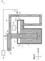
- FIG. 1 is a vertical cross-sectional view of the ozone contacting system 100 when viewed from the front.
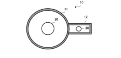
- FIG. 2 is a cross-sectional view of ozone contacting system 100 taken along line AA.
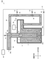
- FIG. 3 is a vertical cross-sectional view of the ozone contacting system 200 viewed from the front.
- FIG. 4 is a vertical cross-sectional view of the ozone contacting system 300 when viewed from the front.
- an intermittent ozone injection method which is an example of an ozone injection method in ozone treatment
- a method bubble column method
- the liquid to be treated is stored in a tank and ozone is blown out as bubbles from the bottom of the tank.
- it is necessary to supply enough ozone to the liquid to be treated so as to sufficiently cause the oxidation reaction to efficiently dissolve the ozone in the liquid to be treated.
- the amount of ozone dissolved in the liquid to be treated corresponds to the amount of ozone consumed by the reaction with the organic matter. Therefore, for example, when excessive ozone is injected into the liquid to be treated, the ozone that does not dissolve in the liquid to be treated is discharged from the liquid to be treated without reacting. The ozone emitted in this way is not only wasteful, but harmful and must be removed. Therefore, it is preferable to reduce the amount of ozone discharged from the liquid to be treated in an unreacted state. On the other hand, for example, a method of gradually injecting a small amount of ozone into the liquid to be treated is conceivable for the purpose of suppressing the amount of ozone released without reacting with the organic matter. However, in this case, since it takes a long time to inject ozone, it is necessary to use, for example, a tank of a size that can ensure a sufficient time for injecting ozone into the liquid to be treated.
- FIG. 1 is a configuration diagram of an ozone contact system 100 in the first embodiment.
- FIG. 1 is a vertical cross-sectional view of the ozone contacting system 100 when viewed from the front.
- FIG. 2 is a cross-sectional view of ozone contacting system 100 taken along line AA.
- the ozone contact system 100 injects ozone 2 into the liquid 1 to be treated from a plurality of injection points (for example, ozone diffusers 21 and 22).
- the ozone contact system 100 is described in detail below.
- the ozone contact system 100 includes, for example, a tank 10 that stores the liquid 1 to be treated, and an inflow channel 20 (hereinafter also referred to as a first channel 20) through which the liquid 1 to be treated is introduced (also referred to as input) into the tank 10.
- a circulation path 30 (hereinafter also referred to as a second flow path 30) for circulating the liquid 1 to be treated in the tank 10; an ozone generator 40 for generating ozone 2; and an exhaust ozone treatment device 50 for treating ozone 2 (hereinafter also referred to as exhaust ozone).
- the ozone generator 40 and the exhaust ozone treatment device 50 are provided outside the tank 10, for example.
- the tank 10 has, for example, a substantially cylindrical tank main body 11 having a bottom and a supply section 12 for supplying the liquid 1 to be treated in the tank main body 11 to the circulation path 30 .
- the supply part 12 is, for example, a channel extending horizontally from the outer wall near the upper end of the tank body 11 .
- the inflow path 20 is, for example, a flow path having an inflow port 20 a through which the liquid to be treated 1 flows and an outflow port 20 b through which the liquid to be treated 1 flows out to the tank main body 11 .
- the inflow path 20 is a flow path whose part including the outflow port 20b extends vertically downward, and the outflow port 20b is provided at a position facing the bottom of the tank body 11 .
- the inflow path 20 has, for example, a height in the vertical direction of the outflow port 20b that is lower than the height of the water surface of the liquid 1 to be treated in the tank body 11 (the height of the water surface when ozone treatment is performed). It is set in a position where After a certain amount of the liquid 1 to be treated has been introduced into the tank body 11, the inflow path 20 may be cut off from the preceding equipment for performing the preceding process by means of a valve (not shown) or the like provided in the inflow path 20.
- an ozone diffuser 21 for injecting ozone 2 into the liquid to be treated 1 flowing in the inflow path 20 is provided inside the inflow path 20, for example.
- the ozone diffuser 21 injects the ozone 2 supplied from the ozone generator 40 through the line L1 (hereinafter also referred to as the first supply pipe L1) into the liquid 1 to be treated.
- the circulation path 30 is, for example, a flow path one of which communicates with the supply section 12 and the other of which communicates with the inflow port 20 c of the inflow path 20 .
- a part of the circulation path 30 that communicates with the supply unit 12 extends vertically downward from the vicinity of the tip of the supply unit 12 , for example.
- the inflow port 20c is provided, for example, at a position whose height in the vertical direction is higher than the height of the water surface of the liquid 1 to be treated in the tank body 11 (the height of the water surface when ozone treatment is performed).
- an ozone diffuser 22 for injecting ozone 2 into the liquid to be treated 1 flowing through the circulation path 30 is provided inside the circulation path 30, for example.
- the ozone diffuser 22 injects the ozone 2 supplied from the ozone generator 40 through a line L2 (hereinafter also referred to as a second supply pipe L2) into the liquid 1 to be treated.
- a valve 41 is provided between the ozone generator 40 and the ozone diffuser 21, for example.
- the amount of ozone 2 supplied to the ozone diffuser 21 is controlled by the opening of the valve 41, for example.
- a valve 42 is provided between the ozone generator 40 and the ozone diffuser 22 .
- the amount of ozone 2 supplied to the ozone diffuser 22 is controlled by the opening of the valve 42, for example.
- the circulation path 30 is provided with an outflow path (not shown) for flowing out the liquid 1 to be treated in the tank 10 to other equipment (for example, equipment for performing the next process, etc.) good.
- the liquid to be treated 1 flows into the vicinity of the bottom of the tank body 11 by, for example, descending through the inflow passage 20, as shown in FIG.
- the ozone diffuser 21 discharges the ozone 2 generated by the ozone generator 40 in a vertically downward direction so that the liquid 1 to be treated descending in the inflow passage 20 is exposed to the ozone. 2 are brought into contact.
- the liquid to be treated 1 that has flowed into the tank main body 11 from the inflow path 20 rises inside the tank main body 11 (outside the inflow path 20).
- the ozone 2 dissolved in the liquid 1 to be treated is gradually decomposed (consumed) by an oxidation reaction with the organic substances contained in the liquid 1 to be treated.
- the liquid to be treated 1 in which the organic matter has been decomposed flows into the circulation path 30 from the supply portion 12 communicating near the upper end of the tank main body 11 by, for example, a suction pump (not shown).
- the ozone diffuser 22 discharges the ozone 2 generated by the ozone generator 40 in the direction of flow of the liquid 1 to be treated (in the example shown in FIG. 1, vertically upward direction), thereby Ozone 2 is further brought into contact with liquid 1 to be treated flowing through 30 .
- the inflow path 20 may stop the inflow of the liquid to be treated 1 into the tank main body 11 .
- the ozone contact system 100 stops the supply of the liquid 1 to be treated and performs concentrated ozone treatment on the stored liquid 1 to be treated. Then, when the ozone treatment for the stored liquid 1 to be treated is completed, the ozone contact system 100 discharges the liquid 1 to be treated for which the ozone treatment has been completed from an outflow path (not shown), and for example, to the tank body 11. The supply of the liquid to be treated 1 is restarted.
- the liquid 1 to be treated that has come into contact with the ozone 2 in the tank 10 is supplied to the circulation path 30 to flow back into the tank 10 .
- the ozone 2 and the liquid 1 to be treated are brought into contact also in the circulation path 30 .
- the ozone contact system 100 it is possible to inject the ozone 2 into the liquid 1 to be treated in stages.
- the ozone contact system 100 it becomes possible to inject the ozone 2 into the liquid 1 to be treated from a plurality of injection points (for example, the ozone diffusers 21 and 22).
- a plurality of injection points for example, the ozone diffusers 21 and 22.
- an amount of ozone 2 corresponding to the amount of ozone 2 consumed by the reaction with the organic substance can be injected into the liquid 1 to be treated in stages. be possible. Therefore, in the ozone contact system 100 according to the first embodiment, it is possible to suppress the ozone 2 discharged to the outside without reacting with the organic substances contained in the liquid 1 to be treated.
- the contact time (reaction time) between the liquid 1 to be treated and the ozone 2 can be made constant by the stirring effect of the circulation of the liquid 1 to be treated. .
- the ozone contact system 100 it is possible to efficiently react the organic matter contained in the liquid 1 to be treated with the ozone 2 .
- FIG. 3 is a configuration diagram of an ozone contact system 200 according to the second embodiment. Specifically, FIG. 3 is a vertical cross-sectional view of the ozone contacting system 200 when viewed from the front.
- the ozone contact system 200 in the second embodiment includes, for example, a tank 10 for storing the liquid 1 to be treated, an inflow path 20 for flowing the liquid 1 to be treated into the tank 10, It has a circulation path 30 for circulating the liquid 1 to be treated in the bath 10, an ozone generator 40 for generating ozone 2, and an exhaust ozone treatment device 50 for treating the ozone 2 after contact with the liquid 1 to be treated.
- the tank 10 has, for example, a substantially cylindrical tank body 11 having a bottom and a supply part 12 for supplying the liquid 1 to be treated in the tank body 11 to the outflow path 30 .
- the ozone 2 is injected into the liquid 1 to be treated from a plurality of injection points (for example, the ozone diffuser 21, the ozone diffuser 22, and the ozone diffuser 23).
- a plurality of injection points for example, the ozone diffuser 21, the ozone diffuser 22, and the ozone diffuser 23.
- an ozone diffuser 23a for injecting ozone 2 into the liquid 1 to be treated that has flowed into the tank body 11 from the inflow path 20 and an ozone diffuser 23a.
- a device 23b (hereinafter also collectively referred to as an ozone diffuser 23) is provided.
- the ozone diffuser 23 injects the ozone 2 supplied from the ozone generator 40 through the line L3 (hereinafter also referred to as the third supply pipe L3) into the liquid 1 to be treated.
- a valve 43 is provided between the ozone generator 40 and the ozone diffuser 23, for example.
- the amount of ozone 2 supplied to the ozone diffuser 23 is controlled by the opening of the valve 43, for example.
- the ozone diffuser 23 emits the ozone generated in the ozone generator 40 in the vertical upward direction, thereby further removing the ozone 2 that has flowed into the tank main body 11 from the inflow passage 20. make contact.
- injection of ozone 2 into the inflow passage 20 injection of ozone 2 by the ozone diffuser 21
- injection of ozone 2 into the circulation passage 30 ozone diffusion
- the ozone 2 is also injected into the liquid 1 to be treated in the tank body 11 .
- the ozone contact system 200 of the second embodiment it becomes possible to inject the ozone 2 into the liquid 1 to be treated stepwise. Therefore, in the ozone contact system 200 according to the second embodiment, it is possible to further suppress ozone discharged to the outside without reacting with organic substances contained in the liquid 1 to be treated. Therefore, in the ozone contact system 200 according to the second embodiment, the organic matter contained in the liquid 1 to be treated and the ozone 2 can be caused to react more efficiently.
- FIG. 4 is a configuration diagram of an ozone contact system 300 in the third embodiment. Specifically, FIG. 4 is a vertical cross-sectional view of the ozone contacting system 300 when viewed from the front.
- the ozone contact system 300 in the third embodiment includes, for example, a tank 10 for storing the liquid 1 to be treated, an inflow path 20 for flowing the liquid 1 to be treated into the tank 10, It has a circulation path 30 for circulating the liquid 1 to be treated in the bath 10, an ozone generator 40 for generating ozone 2, and an exhaust ozone treatment device 50 for treating the ozone 2 after contact with the liquid 1 to be treated.
- the tank 10 has, for example, a substantially cylindrical tank body 11 having a bottom and a supply part 12 for supplying the liquid 1 to be treated in the tank body 11 to the outflow path 30 .
- ozone 2 is applied to the liquid 1 to be treated from a plurality of injection points (for example, the ozone diffuser 21, the ozone diffuser 22, the ozone diffuser 23, and the ozone diffuser 24). inject.
- a plurality of injection points for example, the ozone diffuser 21, the ozone diffuser 22, the ozone diffuser 23, and the ozone diffuser 24. inject.
- an ozone diffuser 22 and an ozone diffuser 24 for injecting ozone 2 into the liquid 1 flowing through the circulation path 30 are provided inside the circulation path 30 in the third embodiment.
- the ozone air diffuser 24 is provided at a position closer to the supply unit 12 than the ozone air diffuser 22, for example.
- the ozone diffuser 24 injects the ozone 2 supplied from the ozone generator 40 through the line L4 into the liquid 1 to be treated.
- a valve 44 is provided between the ozone generator 40 and the ozone diffuser 24, for example.
- the amount of ozone 2 supplied to the ozone diffuser 24 is controlled by the opening of the valve 44, for example.
- the ozone diffuser 24 emits the ozone 2 generated by the ozone generator 40 in the direction of flow of the liquid 1 to be treated (vertical upward direction in the example shown in FIG. Ozone 2 is brought into contact with liquid 1 to be treated flowing through 30 .
- the ozone diffuser 22 discharges the ozone 2 generated in the ozone generator 40 in the direction of flow of the liquid 1 to be treated (in the example shown in FIG. 1, vertically upward direction), thereby causing the ozone to flow through the circulation path 30. Ozone 2 is further brought into contact with the liquid 1 to be treated.
- the ozone 2 is injected into the liquid 1 to be treated at a plurality of locations in the circulation path 30 .
- the ozone contact system 300 of the third embodiment it is possible to inject the ozone 2 into the liquid 1 to be treated in a stepwise manner. Therefore, in the ozone contact system 300 according to the third embodiment, it is possible to further suppress the ozone 2 discharged to the outside without reacting with the organic matter contained in the liquid 1 to be treated. Therefore, in the ozone contact system 300 according to the third embodiment, the organic matter contained in the liquid 1 to be treated and the ozone 2 can be caused to react more efficiently.
- the ozone contact system described in each embodiment it is possible to additionally supply ozone 2 in stages, so that the object to be processed that needs to be oxidatively decomposed by ozone 2 and ozone 2 react efficiently. It becomes possible to let In addition, it becomes possible to supply additional ozone 2 step by step according to the amount of the incineration matter for which the oxidation reaction has been completed. Therefore, it becomes possible to reduce the amount of unreacted ozone.
- the circulation path 30 since the circulation path 30 is provided, the agitation effect of the circulation increases the uniformity of the contact time, uniformizes the reaction time of the ozone 2, and promotes the oxidation reaction. Efficiency can be improved.
- Each of the ozone contact system 100, the ozone contact system 200, and the ozone contact system 300 may be provided with, for example, one or more ozone concentration meters (not shown) for measuring the ozone concentration of the liquid 1 to be treated. good.
- each of the ozone contact system 100, the ozone contact system 200, and the ozone contact system 300 includes, for example, the ozone diffuser 21, the ozone diffuser 22, the ozone diffuser 23, and the ozone diffuser 24, respectively.
- An ozone concentration meter may be provided in the vicinity of the installation position.
- a control device determines the state of contact between the organic matter contained in the liquid to be treated 1 and the ozone 2 based on the measurement results of each ozone concentration meter, and each ozone diffuser detects the liquid 1 to be treated. may control the amount of ozone 2 injected into the
- the control device is, for example, a computer device having a CPU (Computing Processing Unit) and a memory.
- control device may, for example, control the amount of ozone 2 supplied from the ozone generator 40 to each ozone diffuser.
- control device controls the amount of ozone 2 supplied to each ozone diffuser, for example, by controlling the degree of opening of at least one of the valves 41, 42, 43, and 44. It may be something to do.
- the control device injects ozone from an ozone diffuser located near the detected ozone concentration meter. Control may be performed so that the amount of ozone 2 that is absorbed is increased. Further, for example, when an ozone concentration meter that measures an ozone concentration greater than a predetermined upper limit threshold value is detected, the control device detects ozone 2 injected from an ozone diffuser located near the detected ozone concentration meter. may be controlled so that the amount of
- the ozone concentration in the vapor phase portion of the tank body 11 may also be measured. For example, when the ozone concentration in the gas phase portion of the tank body 11 is lower than a predetermined lower threshold value, the control device controls to increase the supply amount of the ozone 2 . Further, for example, when the ozone concentration in the gas phase portion of the tank body 11 is higher than a predetermined upper limit threshold value, the control device performs control to reduce the supply amount of the ozone 2 .
- control device can more efficiently suppress the ozone 2 discharged to the outside without reacting with the organic matter contained in the liquid 1 to be treated. Therefore, the control device can make the organic substance and the ozone 2 react more efficiently.
- the outflow port 20b through which the liquid flows out is close to the bottom of the tank main body 11 .
- the primary side (inlet side) of the exhaust ozone treatment device 50 is provided with an anti-irritant to prevent the intrusion of the liquid to be treated and the material to be treated into the exhaust ozone treatment device 50 .
- a collector may be provided for collecting the liquid to be treated or the object to be treated.
- the shapes of the tank 10, the tank main body 11, the supply part 12, the inflow path 20, and the circulation path 30 are examples.
- the shape of the circulation path 30 may be rectangular instead of cylindrical.
Landscapes
- Life Sciences & Earth Sciences (AREA)
- Hydrology & Water Resources (AREA)
- Engineering & Computer Science (AREA)
- Environmental & Geological Engineering (AREA)
- Water Supply & Treatment (AREA)
- Chemical & Material Sciences (AREA)
- Organic Chemistry (AREA)
- Treatment Of Water By Oxidation Or Reduction (AREA)
Abstract
Description
初めに、第1の実施の形態におけるオゾン接触システム100について説明を行う。図1は、第1の実施の形態におけるオゾン接触システム100の構成図である。図1は、オゾン接触システム100を正面視した場合における垂直断面図である。図2は、オゾン接触システム100のA-A断面図である。
次に、被処理液体1の流れについて説明を行う。
次に、第2の実施の形態におけるオゾン接触システム200について説明を行う。図3は、第2の実施の形態におけるオゾン接触システム200の構成図である。具体的に、図3は、オゾン接触システム200を正面視した場合における垂直断面図である。
図4は、第3の実施の形態におけるオゾン接触システム300の構成図である。具体的に、図4は、オゾン接触システム300を正面視した場合における垂直断面図である。
次に、被処理液体1に対するオゾンの供給量の制御について説明を行う。
10:槽 11:槽本体
12:供給部 20:流入路
20a:流入口 20b:流出口
20c:流入口 21:オゾン散気装置
22:オゾン散気装置 23:オゾン散気装置
23a:オゾン散気装置 23b:オゾン散気装置
24:オゾン散気装置 30:循環路
40:オゾン発生装置 41:弁
42:弁 43:弁
44:弁 50:排オゾン処理装置
100:オゾン接触システム 200:オゾン接触システム
300:オゾン接触システム L1:ライン
L2:ライン L3:ライン
L4:ライン
Claims (4)
- 槽と、
少なくとも一部が前記槽内に設けられた、被処理物を含む液体を下降流で前記槽に流出させる第1流路と、
前記槽外に設けられ、前記槽内の前記液体を前記槽内から流入させ更に流入した前記液体を前記槽内に流出させる第2流路と、
前記第1流路にオゾンを供給する第1供給管と、
前記第2流路にオゾンを供給する第2供給管と、を備えた、オゾン接触システム。 - 更に、前記槽にオゾンを供給する第3供給管を備えたオゾン接触システム。
- 前記第2供給管は、前記第2流路と2箇所以上において連通する、請求項1に記載のオゾン接触システム。
- 請求項1に記載のオゾン接触システムにおけるオゾン接触方法であって、
前記オゾン接触システム内における前記オゾンと前記液体との接触状態を判定し、
前記接触状態に基づき、前記第1流路と前記第2流路とに供給するオゾンの量を制御する、オゾン接触方法。
Priority Applications (3)
| Application Number | Priority Date | Filing Date | Title |
|---|---|---|---|
| JP2023556325A JPWO2023074422A1 (ja) | 2021-10-27 | 2022-10-14 | |
| AU2022379140A AU2022379140A1 (en) | 2021-10-27 | 2022-10-14 | Ozone contact system and ozone contact method |
| CN202280071707.4A CN118159499A (zh) | 2021-10-27 | 2022-10-14 | 臭氧接触系统和臭氧接触方法 |
Applications Claiming Priority (2)
| Application Number | Priority Date | Filing Date | Title |
|---|---|---|---|
| JP2021-175285 | 2021-10-27 | ||
| JP2021175285 | 2021-10-27 |
Publications (1)
| Publication Number | Publication Date |
|---|---|
| WO2023074422A1 true WO2023074422A1 (ja) | 2023-05-04 |
Family
ID=86157693
Family Applications (1)
| Application Number | Title | Priority Date | Filing Date |
|---|---|---|---|
| PCT/JP2022/038454 Ceased WO2023074422A1 (ja) | 2021-10-27 | 2022-10-14 | オゾン接触システム及びオゾン接触方法 |
Country Status (4)
| Country | Link |
|---|---|
| JP (1) | JPWO2023074422A1 (ja) |
| CN (1) | CN118159499A (ja) |
| AU (1) | AU2022379140A1 (ja) |
| WO (1) | WO2023074422A1 (ja) |
Cited By (1)
| Publication number | Priority date | Publication date | Assignee | Title |
|---|---|---|---|---|
| JP7665246B1 (ja) | 2024-09-02 | 2025-04-21 | Wota株式会社 | 混合装置及び混合方法 |
Citations (2)
| Publication number | Priority date | Publication date | Assignee | Title |
|---|---|---|---|---|
| JPH09122664A (ja) * | 1995-10-31 | 1997-05-13 | Meidensha Corp | 加圧型下方注入式オゾン接触槽とその制御方法 |
| JP2007260598A (ja) * | 2006-03-29 | 2007-10-11 | Ohbayashi Corp | オゾン微細気泡による汚染水の処理方法、及びオゾン微細気泡による汚染水の処理装置 |
Family Cites Families (1)
| Publication number | Priority date | Publication date | Assignee | Title |
|---|---|---|---|---|
| JP2001205281A (ja) * | 2000-01-27 | 2001-07-31 | Chiyoda Kohan Co Ltd | 水処理装置 |
-
2022
- 2022-10-14 AU AU2022379140A patent/AU2022379140A1/en active Pending
- 2022-10-14 JP JP2023556325A patent/JPWO2023074422A1/ja active Pending
- 2022-10-14 CN CN202280071707.4A patent/CN118159499A/zh active Pending
- 2022-10-14 WO PCT/JP2022/038454 patent/WO2023074422A1/ja not_active Ceased
Patent Citations (2)
| Publication number | Priority date | Publication date | Assignee | Title |
|---|---|---|---|---|
| JPH09122664A (ja) * | 1995-10-31 | 1997-05-13 | Meidensha Corp | 加圧型下方注入式オゾン接触槽とその制御方法 |
| JP2007260598A (ja) * | 2006-03-29 | 2007-10-11 | Ohbayashi Corp | オゾン微細気泡による汚染水の処理方法、及びオゾン微細気泡による汚染水の処理装置 |
Cited By (2)
| Publication number | Priority date | Publication date | Assignee | Title |
|---|---|---|---|---|
| JP7665246B1 (ja) | 2024-09-02 | 2025-04-21 | Wota株式会社 | 混合装置及び混合方法 |
| JP2026046329A (ja) * | 2024-09-02 | 2026-03-13 | Wota株式会社 | 混合装置及び混合方法 |
Also Published As
| Publication number | Publication date |
|---|---|
| JPWO2023074422A1 (ja) | 2023-05-04 |
| CN118159499A (zh) | 2024-06-07 |
| AU2022379140A1 (en) | 2024-05-16 |
Similar Documents
| Publication | Publication Date | Title |
|---|---|---|
| KR20100017992A (ko) | 밸러스트 수 탱크 순환 처리 시스템 | |
| JP7745140B2 (ja) | 電解水散布装置 | |
| TWI887494B (zh) | 氣體溶解液供給裝置及藉由氣體溶解液供給裝置執行的方法 | |
| CN118159499A (zh) | 臭氧接触系统和臭氧接触方法 | |
| CN115711439B (zh) | 对水和空气具有杀菌功能的蒸发型加湿器及其使用方法 | |
| WO2023074421A1 (ja) | オゾン接触システム及びオゾン接触方法 | |
| JP4034519B2 (ja) | ウェハ洗浄装置及びウェハ洗浄方法 | |
| JP2021044593A5 (ja) | ||
| KR102171795B1 (ko) | 오존수 공급 시스템 | |
| JP7692136B2 (ja) | 電解水生成装置 | |
| TWI916567B (zh) | 空間淨化裝置 | |
| KR100904460B1 (ko) | 오존수 혼합액 공급 장치 및 방법과, 이를 이용한 기판처리 설비 | |
| KR970703189A (ko) | 살균을 위해 사용된 산화 에틸렌 가스의 처리 방법 및 장치(process and device for disposing of ethylene oxide gas used for sterilisation purposes) | |
| JP2024101855A (ja) | 基板処理方法及び基板処理装置 | |
| KR101793968B1 (ko) | 과산화수소 분해반응기 | |
| JP2023110945A (ja) | 排ガス処理システムおよび排ガス処理方法 | |
| JP2006167616A (ja) | 中和装置 | |
| CN117042816B (zh) | 空气净化装置 | |
| JP2024035806A (ja) | 中和処理装置 | |
| KR101840987B1 (ko) | 고도산화 수처리장치 및 수처리방법 | |
| JP2014023983A (ja) | アルカリ性原水のph処理装置 | |
| JP2005103374A (ja) | 水処理装置 | |
| CN121775694A (zh) | 一种混无机酸臭氧水制备系统 | |
| JP2023089994A (ja) | 電解水生成装置 | |
| KR20250035782A (ko) | 처리액공급장치 및 기판처리장치 |
Legal Events
| Date | Code | Title | Description |
|---|---|---|---|
| 121 | Ep: the epo has been informed by wipo that ep was designated in this application |
Ref document number: 22886750 Country of ref document: EP Kind code of ref document: A1 |
|
| ENP | Entry into the national phase |
Ref document number: 2023556325 Country of ref document: JP Kind code of ref document: A |
|
| WWE | Wipo information: entry into national phase |
Ref document number: 202280071707.4 Country of ref document: CN |
|
| WWE | Wipo information: entry into national phase |
Ref document number: 2401002687 Country of ref document: TH |
|
| ENP | Entry into the national phase |
Ref document number: 2022379140 Country of ref document: AU Date of ref document: 20221014 Kind code of ref document: A |
|
| NENP | Non-entry into the national phase |
Ref country code: DE |
|
| 122 | Ep: pct application non-entry in european phase |
Ref document number: 22886750 Country of ref document: EP Kind code of ref document: A1 |