WO2023074102A1 - 情報処理装置 - Google Patents
情報処理装置 Download PDFInfo
- Publication number
- WO2023074102A1 WO2023074102A1 PCT/JP2022/032075 JP2022032075W WO2023074102A1 WO 2023074102 A1 WO2023074102 A1 WO 2023074102A1 JP 2022032075 W JP2022032075 W JP 2022032075W WO 2023074102 A1 WO2023074102 A1 WO 2023074102A1
- Authority
- WO
- WIPO (PCT)
- Prior art keywords
- nudge
- user
- information
- group
- target
- Prior art date
- Legal status (The legal status is an assumption and is not a legal conclusion. Google has not performed a legal analysis and makes no representation as to the accuracy of the status listed.)
- Ceased
Links
Images






Classifications
-
- G—PHYSICS
- G06—COMPUTING OR CALCULATING; COUNTING
- G06F—ELECTRIC DIGITAL DATA PROCESSING
- G06F16/00—Information retrieval; Database structures therefor; File system structures therefor
- G06F16/90—Details of database functions independent of the retrieved data types
- G06F16/95—Retrieval from the web
- G06F16/953—Querying, e.g. by the use of web search engines
- G06F16/9536—Search customisation based on social or collaborative filtering
-
- G—PHYSICS
- G06—COMPUTING OR CALCULATING; COUNTING
- G06F—ELECTRIC DIGITAL DATA PROCESSING
- G06F16/00—Information retrieval; Database structures therefor; File system structures therefor
- G06F16/20—Information retrieval; Database structures therefor; File system structures therefor of structured data, e.g. relational data
- G06F16/23—Updating
- G06F16/2358—Change logging, detection, and notification
-
- G—PHYSICS
- G06—COMPUTING OR CALCULATING; COUNTING
- G06F—ELECTRIC DIGITAL DATA PROCESSING
- G06F16/00—Information retrieval; Database structures therefor; File system structures therefor
- G06F16/90—Details of database functions independent of the retrieved data types
- G06F16/95—Retrieval from the web
- G06F16/953—Querying, e.g. by the use of web search engines
- G06F16/9535—Search customisation based on user profiles and personalisation
-
- G—PHYSICS
- G06—COMPUTING OR CALCULATING; COUNTING
- G06Q—INFORMATION AND COMMUNICATION TECHNOLOGY [ICT] SPECIALLY ADAPTED FOR ADMINISTRATIVE, COMMERCIAL, FINANCIAL, MANAGERIAL OR SUPERVISORY PURPOSES; SYSTEMS OR METHODS SPECIALLY ADAPTED FOR ADMINISTRATIVE, COMMERCIAL, FINANCIAL, MANAGERIAL OR SUPERVISORY PURPOSES, NOT OTHERWISE PROVIDED FOR
- G06Q10/00—Administration; Management
- G06Q10/06—Resources, workflows, human or project management; Enterprise or organisation planning; Enterprise or organisation modelling
Definitions
- One aspect of the present invention relates to an information processing device.
- Patent Document 1 describes a system that encourages users to change their behavior by nudges, which are mechanisms based on cognitive biases that encourage individuals and society to voluntarily take desirable behaviors.
- the nudges mentioned above are considered to wear out.
- the wear of the nudge means that the behavior modification effect of the nudge decreases due to repeated intervention (recommendation to the user).
- the behavior modification effect will recover after a certain period of time.
- no means have been proposed to adequately verify the effectiveness of such nudge wear and recovery.
- One aspect of the present invention has been made in view of the above circumstances, and aims to appropriately verify the effects of nudge wear and recovery.
- An information processing apparatus verifies the effect of wear by being recommended multiple times for a nudge, which is a device that encourages a user to voluntarily take a desired action, and evaluates the effect of wearing after wearing.
- a verification group storage unit for storing a verification group management table defining a plurality of verification groups each including a plurality of nudge groups having mutually different target nudges;
- a user information storage unit that stores a user management table that defines information specifying the verification group and nudge group to which each of the users belongs, and recommendation information that is recommended information for each of a plurality of users.
- a user nudge storage unit that stores a user nudge definition table that defines a target nudge as a value at the time of starting recommendation of the recommendation information; , the recommended information in the user nudge definition table is changed to information different from the target nudge, and after the change, at the timing when a predetermined period of time during which multiple recommendations are possible has passed, the recommended information in the user nudge definition table is changed to the target a nudge modification unit configured to perform a change to a nudge, and obtain a target nudge recommendation result for each of said users, so that the target nudge recommendation result is newly defined in a user management table.
- an updating unit for updating the user management table.
- An information processing apparatus is an information processing apparatus for verifying the effect of nudge wear and recovery.
- a plurality of verification groups including a plurality of nudge groups are defined, and a verification group and a nudge group to which each of the plurality of users belongs are defined. Then, for each of a plurality of users, a target nudge (a different target nudge for each nudge group to which they belong) is specified as a value at the start of recommendation in the recommendation information, and a predetermined period during which multiple recommendations can be made is specified.
- the recommended information is changed to information different from the target nudge, and after a predetermined period of time during which multiple recommendations are possible, the recommended information is changed again to the target nudge.
- the target nudge will gradually wear out as the recommendation is made a plurality of times in a state where the target nudge is defined as the value at the start of recommendation. Acquiring the recommendation result of the target nudge that gradually wears out in this way and defining it in the user management table makes it possible to appropriately acquire information suitable for verifying the wear of the target nudge.
- the target nudge after the target nudge is worn out, it is assumed that the effect of the target nudge once worn out is restored by recommending other information a plurality of times for a predetermined period. After that, the target nudge is recommended again, and the recommendation result is acquired and defined in the user management table, so that information suitable for verification of recovery of the target nudge can be appropriately acquired. According to such a configuration, it is possible to appropriately acquire information suitable for verifying the effect of nudge wear and recovery, and contribute to appropriate verification of the effect of nudge wear and recovery.
- the effects of nudge wear and recovery can be properly verified.
- FIG. 1 is a diagram illustrating a series of flows for prompting a user's behavioral change by nudging.
- FIG. 2 is a diagram illustrating nudge wear.
- FIG. 3 is a diagram for explaining a demonstration experiment relating to verification of nudge wear and recovery effects.
- FIG. 4 is a diagram explaining each verification group in the demonstration experiment shown in FIG.
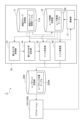
- FIG. 5 is a functional block diagram of the nudge management device according to the embodiment;
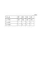
- FIG. 6 is a diagram showing an example of a user nudge definition table.
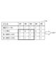
- FIG. 7 is a diagram illustrating an example of a verification group management table;
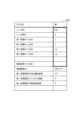
- FIG. 8 is a diagram showing an example of a user management table.
- FIG. 9 is a diagram showing an example of a user registration management table.
- FIG. 10A and 10B are diagrams for explaining how to specify the allocation destination.
- FIG. 11 is a diagram illustrating change (switching) of the target nudge.
- FIG. 12 is a sequence diagram showing new user distribution processing.
- FIG. 13 is a sequence diagram showing a target nudge change (switch) process.
- 14 is a diagram illustrating a hardware configuration of a nudge management device according to the embodiment; FIG.
- FIG. 1 is a diagram illustrating a series of flows for prompting a user's behavioral change by nudging.
- FIG. 2 is a diagram illustrating nudge wear.
- a nudge is a mechanism or mechanism based on cognitive biases that encourages users to voluntarily take desirable actions for individuals and society.
- a nudge is a display such as a message displayed on a communication terminal such as a smartphone
- FIG. 1 assumes a scene in which user Y is heading to bus stop 800 to board bus 500 .
- a bus 500 (next bus) on which user Y is expected to board is highly congested.
- a push notification is sent to the communication terminal 100 such as a smart phone of the user Y through a predetermined application (for example, a bus application that assists getting on the bus).
- the push notification is a notification related to a nudge that prompts the user to change their behavior, specifically, a notification related to a nudge that prompts the user to get on a bus (recommended bus) other than the crowded next bus 500 .
- Timing of nudge intervention may be determined, for example, based on information obtained through an application of communication terminal 100 (“bus application” in the above example), user Y's location information, and the like. In this embodiment, a detailed description of the timing of nudge intervention is omitted. For effective nudges, for example, based on information acquired through the application of the communication terminal 100 (“bus application” in the above example), select the nudge that has the highest behavioral change effect in the current scene. can be considered.
- FIG. 3 is a diagram for explaining a demonstration experiment relating to verification of nudge wear and recovery effects.
- FIG. 4 is a diagram explaining each verification group in the demonstration experiment shown in FIG.
- the demonstration experiment will be conducted in units of multiple nudge groups with different target nudges, which are nudges that verify the effects of wear and recovery.
- target nudges which are nudges that verify the effects of wear and recovery.
- FIG. 3 a nudge P group whose target nudge is nudge p, a nudge A group whose target nudge is nudge a, a nudge B group whose target nudge is nudge b, and a nudge C group whose target nudge is nudge c. is exemplified.
- Each nudge group includes a plurality of users (about 300 users in the example of FIG. 3) to whom the target nudge is recommended.
- the demonstration period is divided into three sections (periods): the first section, the second section following the first section, and the third section following the second section.
- the target nudge is recommended multiple times for each user in each nudge group.
- nudge a which is the target nudge
- Such a first section in which the same nudge is repeatedly recommended for a certain period of time is a section related to verification of wear of the target nudge.
- the second section information different from the target nudge is recommended to each user in each nudge group.
- a common nudge p is shown as information different from the target nudge.
- the nudge p here is described as a nudge for convenience of explanation, but it may be a simple message without a nudge element.
- the second section may be a section in which the target nudge is not recommended, for example, it may be a section in which no nudge is recommended.
- the nudge P group is not switched depending on the section, and the nudge p is always recommended.
- the nudge p of the nudge P group is not a nudge for verifying the effect of its own wear and recovery, but for example, when evaluating (verifying) other target nudges a, b, and c. It is used for reference information, etc.
- the target nudge is recommended multiple times again for each user in each nudge group.
- nudge a which is the target nudge
- the above-mentioned second section and third section are sections related to the verification of the recovery of the target nudge worn out in the first section (recovery of the target nudge due to the recommendation of information different from the target nudge in the second section). . In this way, in the demonstration experiment, since the demonstration period is divided and the nudge is determined for each section, it is necessary to switch the nudge to be recommended to the user at an appropriate timing (details will be described later).
- each nudge group (nudge A group, nudge B group, nudge C group) included in one verification group (for example, the first verification group) is treated as a unit of a verification group including a plurality of nudge groups. , nudge P group). Then, when the number of users belonging to each nudge group included in the first verification group reaches the target value, the verification group in which the new user is registered is changed to the next verification group (for example, the second verification group).
- New users are assigned to each nudge group (nudge D group, nudge E group, nudge F group, nudge G group) included in the two verification groups. In this way, in the demonstration experiment, it is necessary to appropriately distribute new users to each nudge group so that the number of users in each nudge group does not become uneven when registering new users (details will be described later). In the following, the new user's nudge group sorting process and section switching process, which are performed to properly conduct the demonstration experiment, will be mainly described.
- FIG. 5 is a functional block diagram of the nudge management device 10 included in the nudge recommendation system 1 (information processing device) according to the embodiment.
- the nudge recommendation system 1 is a system that recommends nudges to users, and is a system that performs the above-described demonstration experiment.
- the nudge recommendation system 1 includes an application 101 of a communication terminal 100, a user nudge storage unit 200, and a nudge management device .
- the nudge recommendation system 1 actually includes applications 101 of a plurality of communication terminals 100 of different users, but for convenience of explanation, only the application 101 of one communication terminal 100 will be explained. .
- the communication terminal 100 may be any terminal capable of wireless communication, such as a smartphone, tablet terminal, or PC terminal.
- the application 101 may be any application that can be activated in the communication terminal 100, such as a bus application for assisting boarding of the bus.
- the user nudge storage unit 200 is a database that stores a user nudge definition table 200a that defines recommended information, which is recommended information for each of a plurality of users.
- FIG. 6 is a diagram showing an example of the user nudge definition table 200a.
- a user ID is information that uniquely identifies a user.
- the nudge ID1 is information that uniquely identifies the psychological bias associated with the recommended nudge.
- Psychological bias includes, for example, loss aversion bias, tuning bias, and the like.
- the nudge ID2 is information that uniquely identifies the type of recommended nudge.
- the values of the nudge ID1 and nudge ID2 that uniquely identify the target nudge are used as recommendation information at the start of recommendation. Defined.
- the recommendation information is changed by changing the values of the nudge ID1 and the nudge ID2 in the user nudge definition table 200a (details will be described later).
- the user nudge storage unit 200 may store information on multiple types of nudges.
- the user nudge storage unit 200 may associate and store, for example, an intervention condition, a content of an action to be encouraged, a behavior modification effect, and an incentive as information associated with the nudge ID1 and ID2 described above.
- the intervention condition is information indicating in what cases the nudge is a candidate for intervention, and is defined as, for example, "when the bus to be boarded is congested.”
- the content of the action to be urged is the specific content of the action that the nudge urges the user to take, and is defined, for example, as "get on the next bus that is not crowded".
- the behavior modification effect is information indicating the degree (probability) of the user taking the action prompted by the nudge when nudge intervention is performed, and is defined as "10%", for example.
- An incentive is an incentive that a user receives when the user performs an action prompted by a nudge, and is defined as "point 10p", for example.
- the nudge management device 10 verifies the effect of wear by being recommended multiple times for nudges, which is a mechanism for prompting the user to voluntarily take a desired action, and evaluates the effect of wearing after wearing. It is a device related to the verification of the effect of recovery by The nudge management device 10 is a device that performs the above-described new user nudge group sorting process and section switching process.
- the nudge management device 10 includes a verification group storage unit 11, a user information storage unit 12, a distribution destination management unit 13, a distribution ratio determination unit 14, a nudge determination unit 15, a nudge change unit 16, and an update unit 17. , is equipped with
- the verification group storage unit 11 is a database that stores a verification group management table 11a that defines a plurality of verification groups each including a plurality of nudge groups with different target nudges.
- FIG. 7 is a diagram showing an example of the verification group management table 11a.
- the verification group management table 11a includes, for example, a verification group ID that uniquely identifies a verification group, a nudge group ID that uniquely identifies a nudge group, first section nudges ID1 and ID2, The second section nudges ID1 and ID2, the third section nudges ID1 and ID2, .
- the nudge ID1 is information that uniquely identifies the psychological bias associated with the recommended nudge.
- the nudge ID2 is information that uniquely identifies the type of recommended nudge.
- the recommended information is specified by the nudge ID1 and the nudge ID2.
- two nudge groups of nudge group ID: A and nudge group ID: B belonging to the same verification group ID are shown. Then, for each nudge group, a nudge ID to be recommended in each of the first section to the third section is defined.
- the user information storage unit 12 is a database that stores a user management table 12a that defines information specifying the verification group and nudge group to which each of a plurality of users belongs.
- FIG. 8 is a diagram showing an example of the user management table 12a.
- the user management table 12a includes, for example, a user ID, a nudge group ID, first section nudges ID1 and ID2, second section nudges ID1 and ID2, and third section nudges ID1 and ID2. , . are stipulated.
- the demonstration start date is the date on which the first nudge intervention took place.
- the first section total number of push notifications is the total number of push notifications of the first section nudge to the user in the first section.
- the first section cumulative nudge intervention count is the cumulative number of first section nudge interventions for the user in the first section.
- the first section cumulative number of behavioral changes is the cumulative number of behavioral changes corresponding to the user's first section nudging in the first section.
- FIG. 8 only the cumulative number of push notifications, the cumulative number of nudge interventions, and the cumulative number of behavioral changes in the first section are specified. defines the cumulative number of push notifications, the cumulative number of nudge interventions, and the cumulative number of behavioral changes for each of the first to third sections.
- the other information in FIG. 8 is information updated by the updating unit 17 according to the recommendation result to the user. .
- the distribution destination management unit 13 identifies a distribution destination verification group (hereinafter sometimes referred to as a current verification group) to be distributed when a new user is registered from among a plurality of verification groups.
- FIG. 9 is a diagram showing an example of the user registration management table 13a.
- the allocation destination management unit 13 stores a user registration management table 13a shown in FIG. 9, and specifies the current verification group based on the user registration management table 13a.
- the current verification group ID, the target number of samples for each nudge group, and the ON/OFF state of the group ID automatic switching mode are defined in association with each other.
- the current verification group ID is information that uniquely identifies the verification group to which the data is to be distributed.
- the target number of samples for each nudge group is the target number of samples (target value) for each nudge group included in the verification group indicated by the current verification group ID.
- the group ID automatic switching mode is information that defines whether to automatically switch (ON) or not (OFF) the current verification group ID when a condition is satisfied.
- the distribution destination management unit 13 determines whether the number of users belonging to multiple nudge groups included in the current verification group has reached the target value. That is, the allocation destination management unit 13 identifies the nudge group ID of the current verification group and the nudge ID linked to each nudge group ID from the verification group management table 11a. For example, in the example shown in FIG. 10, nudge group IDs: A, B, and P linked to the current verification group ID: 1 are specified in the verification group management table 11a. Then, in the user management table 12a, the allocation destination management unit 13 extracts the user IDs of the users associated with the respective nudge group IDs specified above, and determines whether or not the number of users has reached the target value. do.
- the target value here is the target number of samples defined in the user registration management table 13a. Note that the target number of samples may be manually changeable by the system operator.
- the change processing is processing such as a change promotion mail prompting the system operator to manually change the verification group when the group ID automatic switching mode is turned off. Further, the change processing here is processing for automatically changing the current verification group ID defined in the verification group management table 11a when the group ID automatic switching mode is ON.
- the distribution ratio determination unit 14 derives the number of users (the number of active users) in which the target nudge has intervened one or more times for each nudge group of the current verification group, and according to the number of active users, each Determines the allocation ratio to the nudge group. For example, when a new user is registered, the distribution ratio determination unit 14 first identifies the current verification group from the user registration management table 13a (see FIG. 9) of the distribution destination management unit 13. FIG. Then, the distribution ratio determination unit 14 identifies the nudge group ID of the current verification group and the nudge IDs linked to each nudge group ID from the verification group management table 11a.
- the distribution ratio determination unit 14 determines that the user to which each of the nudge group IDs identified above is linked in the user management table 12a (see FIG. 8) and that the total number of nudge interventions in the first section is 1
- the user IDs of the above active users are extracted.
- the distribution ratio determination unit 14 determines the distribution ratio to each nudge group according to the number of active users in each nudge group. For example, assume that the number of active users (number of samples) of the nudge group IDs: A, B, and P shown in FIG. 10 is 11, 12, and 5, respectively. In this case, the allocation ratios to the nudge group IDs: A, B, and P are 1/11, 1/12, and 1/5.
- the nudge determination unit 15 determines the nudge group to which the new user belongs based on the distribution ratio described above. For example, if the allocation ratios to the nudge group IDs: A, B, and P determined by the allocation ratio determination unit 14 are 1/11, 1/12, and 1/5, the nudge determination unit 15 determines the allocation ratios , the nudge group to which the new user belongs is determined (the nudge group to which the new user belongs is determined with such a probability).
- the updating unit 17 updates the user management table 12a (see FIG. 8) regarding the new user. Specifically, in the user management table 12a, the update unit 17 registers the user ID of the new user, the nudge group ID determined by the nudge determination unit 15, and the nudge ID of each section. Further, the update unit 17 registers the user ID of the new user and the information of the nudge ID1 and ID2 of the first section in the user nudge definition table 200a (see FIG. 6).
- the nudge change unit 16 changes the recommendation information in the user nudge definition table from the target nudge to information different from the target nudge at the timing when a predetermined period (for example, 14 days) has passed since the start of the recommendation so that multiple recommendations can be made. do. That is, the nudge change unit 16, as shown in FIGS. 11(a) and 11(b), performs In the user nudge definition table 200a, the recommended information is rewritten to the information of the second section nudge ID1, ID2 of the user management table 12a.
- a predetermined period for example, 14 days
- the nudge change unit 16 changes the recommendation information in the user nudge definition table to the target nudge again at the timing when a predetermined period (for example, 14 days) has passed after the above change, during which multiple recommendations can be made. That is, the nudge change unit 16 changes the recommendation information again to the information of the target nudge (first section nudge) in the user nudge definition table 200a at the timing when it is assumed that a plurality of recommendations have been completed in the second section nudge. rewrite to The nudge changing unit 16 changes to the nudge of the next section at the timing when the predetermined period has passed in this way, and if the nudge of the next section is not registered, the change (switching) is not performed. good.
- a predetermined period for example, 14 days
- the updating unit 17 acquires the target nudge recommendation result for the user, and updates the user management table 12a so that the target nudge recommendation result is newly defined in the user management table 12a (see FIG. 8). Specifically, the updating unit 17 updates the total number of push notifications, the total number of nudge interventions, and the total number of behavioral changes in the user management table 12a (see FIG. 8) for at least the section in which the target nudge is recommended.
- FIG. 12 is a sequence diagram showing new user distribution processing.
- the allocation destination management unit 13 extracts the nudge group ID of the current verification group and the nudge IDs linked to each nudge group ID from the verification group management table 11a (step S1 ). Then, the user ID of the user linked to each nudge group ID identified above is extracted from the user management table 12a by the allocation destination management unit 13 (step S2).
- step S3 the number of users in each nudge group of the current verification group is counted (step S3), and it is determined whether or not the number of users has reached the target value.
- the distribution destination management unit 13 sends a change promotion mail to the system operator to prompt the system operator to manually change the verification group (step S4).
- the system operator may manually update the verification group, for example (step S5).
- the system operator may manually update the verification group management table 11a as necessary (step S6).
- step S7 When a new user is registered from the application 101 in a state where the current verification group has been determined in this way (step S7), the new user's information is first registered in the user nudge definition table 200a. Then, the distribution ratio determination unit 14 is requested to confirm the new user (step S8), and the current verification group is specified in the distribution ratio determination unit 14 (step S9). A nudge group ID and a nudge ID linked to each nudge group ID are extracted (step S10).
- the distribution ratio determining unit 14 extracts the number of users (the number of active users) in which the target nudge has intervened one or more times for each nudge group of the current verification group (step S11). Then, the distribution ratio to each nudge group is calculated by the distribution ratio determining unit 14 according to the number of active users in each nudge group (step S12). The distribution ratio determination unit 14 calculates and outputs the distribution ratio to the nudge determination unit 15 (step S13).
- the nudge group to which the new user belongs is determined in the nudge determination unit 15 based on the distribution ratio described above (step S14).
- the user ID of the new user is registered in the user management table 12a by the update unit 17, and the nudge group ID and the nudge ID of each section determined by the nudge determination unit 15 are registered (step S15).
- the update unit 17 registers the user ID of the new user and the information of the nudge ID1 and ID2 of the first section in the user nudge definition table 200a (see FIG. 6) (step S15).
- step S17 When the information of the nudge ID1 and ID2 of the first section is registered as recommendation information in the user nudge definition table 200a, recommendation of the target nudge to the application 101 is started (step S17). Then, the recommendation result is acquired (step S18), and the user management table 12a is updated based on the acquired information (step S19).
- FIG. 13 is a sequence diagram showing a target nudge change (switch) process.
- the target nudge information of the first section is registered as recommendation information
- the target nudge recommendation to the application 101 is started (step S101), and the recommendation result is acquired (step S102).
- the user management table 12a is updated based on the acquired information (step S103).
- the nudge changing unit 16 determines whether or not a predetermined period of time (for example, 14 days) during which a plurality of recommendations can be made has passed (step S104). If the predetermined period has not elapsed here, no nudge change is implemented.
- a predetermined period of time for example, 14 days
- the nudge change unit 16 changes the recommended information to the information of the second section nudges ID1 and ID2, which are information other than the target nudge, in the user nudge definition table 200a. (Step S105). After the recommendation information is changed, the new recommendation information is recommended again.
- the nudge recommendation system 1 verifies the effect of nudge wear by being recommended multiple times, and the effect of recovery due to the passage of time after nudge, which is a device that encourages the user to voluntarily take a desired action.
- an information processing apparatus relating to the verification of the above which includes a verification group storage unit 11 storing a verification group management table 11a defining a plurality of verification groups including a plurality of nudge groups with mutually different target nudges; , a user information storage unit 12 that stores a user management table 12a that defines information specifying verification groups and nudge groups to which each user belongs, and a table that defines recommendation information that is information recommended for each of a plurality of users.
- a user nudge storage unit 200 that stores a user nudge definition table 200a that defines a target nudge as a value at the start of recommendation of the recommendation information; , the recommended information in the user nudge definition table 200a is changed to information different from the target nudge, and after the change, the recommended information in the user nudge definition table 200a is changed at the timing when a predetermined period of time during which multiple recommendations are possible has passed.
- a nudge change unit 16 configured to execute a change to a target nudge; and a target nudge recommendation result for each user, and the target nudge recommendation result is newly defined in the user management table 12a.
- an updating unit 17 for updating the user management table 12a.
- the nudge recommendation system 1 is an information processing device for verifying the effects of nudge wear and recovery.
- a plurality of verification groups including a plurality of nudge groups are defined, and the verification group and nudge group to which each of the plurality of users belongs are defined.
- a target nudge (a different target nudge for each nudge group to which they belong) is specified as a value at the start of recommendation in the recommendation information, and a predetermined period during which multiple recommendations can be made is specified.
- the recommended information is changed to information different from the target nudge, and after a predetermined period of time during which multiple recommendations are possible, the recommended information is changed again to the target nudge.
- the target nudge will gradually wear out as the recommendation is made a plurality of times in a state where the target nudge is defined as the value at the start of recommendation. Acquiring the recommendation result of the target nudge that gradually wears out in this way and defining it in the user management table 12a makes it possible to appropriately acquire information suitable for verifying the wear of the target nudge.
- the target nudge after the target nudge is worn out, it is assumed that the effect of the target nudge once worn out is restored by recommending other information a plurality of times for a predetermined period. After that, the target nudge is recommended again, and the recommendation result is acquired and defined in the user management table 12a, so that information suitable for verification of recovery of the target nudge can be appropriately acquired. According to such a configuration, it is possible to appropriately acquire information suitable for verifying the effect of nudge wear and recovery, and contribute to appropriate verification of the effect of nudge wear and recovery.
- the nudge recommendation system 1 identifies, from among a plurality of verification groups, a verification group to be distributed when a new user is registered, and the number of users belonging to a plurality of nudge groups included in the verification group of the distribution destination reaches a target value. It further includes a distribution destination management unit 13 that determines whether or not the distribution destination verification group is reached, and if the distribution destination verification group is changed. According to such a configuration, when the number of users involved in verification reaches the target value, the verification group in which the new user is registered is switched. In this way, it is possible to prevent bias in the number of users included in each verification group. As a result, it is possible to obtain information suitable for verifying wear and recovery effects evenly for various target nudges.
- the nudge recommendation system 1 derives the number of all users who have been intervened by the target nudge one or more times for each nudge group of the verification group to be assigned, and according to the number of users, assigns a ratio to each nudge group. and a nudge determination unit 15 that determines a nudge group to which the new user belongs based on the allocation ratio at the time of registration of the new user. Based on the information determined by the unit 15, the user management table 12a is updated with respect to the new user. In this way, the ratio of allocation to each nudge group is determined by the number of users (active users) to whom the target nudge has intervened one or more times, and the nudge group to which the new user belongs is determined based on the ratio.
- the nudge management device 10 may be physically configured as a computer device including a processor 1001, a memory 1002, a storage 1003, a communication device 1004, an input device 1005, an output device 1006, a bus 1007 and the like.
- the term "apparatus” can be read as a circuit, device, unit, or the like.
- the hardware configuration of the nudge management device 10 may be configured to include one or more of each device shown in the figure, or may be configured without some of the devices.
- Each function of the nudge management device 10 is performed by loading predetermined software (programs) on hardware such as the processor 1001 and the memory 1002, the processor 1001 performs calculations, communication by the communication device 1004, the memory 1002 and storage. It is realized by controlling reading and/or writing of data in 1003 .
- the processor 1001 for example, operates an operating system and controls the entire computer.
- the processor 1001 may be configured with a central processing unit (CPU) including an interface with peripheral devices, a control device, an arithmetic device, registers, and the like.
- control functions such as the nudge modifier 16 may be implemented by the processor 1001 .
- the processor 1001 also reads programs (program codes), software modules and data from the storage 1003 and/or the communication device 1004 to the memory 1002, and executes various processes according to them.
- programs program codes
- software modules software modules
- data data from the storage 1003 and/or the communication device 1004
- the program a program that causes a computer to execute at least part of the operations described in the above embodiments is used.
- control functions such as the nudge change unit 16 may be stored in the memory 1002 and implemented by a control program running on the processor 1001, and other functional blocks may be similarly implemented.
- control program running on the processor 1001
- other functional blocks may be similarly implemented.
- Processor 1001 may be implemented with one or more chips.
- the program may be transmitted from a network via an electric communication line.
- the memory 1002 is a computer-readable recording medium, and is composed of at least one of, for example, ROM (Read Only Memory), EPROM (Erasable Programmable ROM), EEPROM (Electrically Erasable Programmable ROM), RAM (Random Access Memory), etc. may be
- ROM Read Only Memory
- EPROM Erasable Programmable ROM
- EEPROM Electrical Erasable Programmable ROM
- RAM Random Access Memory
- the memory 1002 may also be called a register, cache, main memory (main storage device), or the like.
- the memory 1002 can store executable programs (program codes), software modules, etc. for implementing a wireless communication method according to an embodiment of the present invention.
- the storage 1003 is a computer-readable recording medium, for example, an optical disc such as a CDROM (Compact Disc ROM), a hard disk drive, a flexible disc, a magneto-optical disc (for example, a compact disc, a digital versatile disc, a Blu-ray (registered disk), smart card, flash memory (eg, card, stick, key drive), floppy disk, magnetic strip, and/or the like.
- Storage 1003 may also be called an auxiliary storage device.
- the storage medium described above may be, for example, a database, server, or other suitable medium including memory 1002 and/or storage 1003 .
- the communication device 1004 is hardware (transmitting/receiving device) for communicating between computers via a wired and/or wireless network, and is also called a network device, network controller, network card, communication module, etc., for example.
- the input device 1005 is an input device (for example, keyboard, mouse, microphone, switch, button, sensor, etc.) that receives input from the outside.
- the output device 1006 is an output device (eg, display, speaker, LED lamp, etc.) that outputs to the outside. Note that the input device 1005 and the output device 1006 may be integrated (for example, a touch panel).
- Each device such as the processor 1001 and the memory 1002 is connected by a bus 1007 for communicating information.
- the bus 1007 may be composed of a single bus, or may be composed of different buses between devices.
- the nudge management device 10 includes hardware such as a microprocessor, a digital signal processor (DSP), an ASIC (Application Specific Integrated Circuit), a PLD (Programmable Logic Device), and an FPGA (Field Programmable Gate Array). , and part or all of each functional block may be implemented by the hardware.
- processor 1001 may be implemented with at least one of these hardware.
- LTE Long Term Evolution
- LTE-A Long Term Evolution-Advanced
- SUPER 3G IMT-Advanced
- 4G 5G
- FRA Full Radio Access
- W-CDMA registered trademark
- GSM registered trademark
- CDMA2000 Code Division Multiple Access 2000
- UMB Universal Mobile Broad-band
- IEEE 802.11 Wi-Fi
- IEEE 802.16 WiMAX
- IEEE 802.20 UWB (Ultra-Wide Band)
- Bluetooth® other suitable systems and/or extended next generation systems based on these.
- Input and output information may be saved in a specific location (for example, memory) or managed in a management table. Input/output information and the like can be overwritten, updated, or appended. The output information and the like may be deleted. The entered information and the like may be transmitted to another device.
- the determination may be made by a value represented by one bit (0 or 1), by a true/false value (Boolean: true or false), or by numerical comparison (for example, a predetermined value).
- notification of predetermined information is not limited to being performed explicitly, but may be performed implicitly (for example, not notifying the predetermined information). good too.
- Software whether referred to as software, firmware, middleware, microcode, hardware description language or otherwise, includes instructions, instruction sets, code, code segments, program code, programs, subprograms, and software modules. , applications, software applications, software packages, routines, subroutines, objects, executables, threads of execution, procedures, functions, and the like.
- software, instructions, etc. may be transmitted and received via a transmission medium.
- the software can be used to access websites, servers, or other When transmitted from a remote source, these wired and/or wireless technologies are included within the definition of transmission media.
- data, instructions, commands, information, signals, bits, symbols, chips, etc. may refer to voltages, currents, electromagnetic waves, magnetic fields or magnetic particles, light fields or photons, or any of these. may be represented by a combination of
- information, parameters, etc. described in this specification may be represented by absolute values, may be represented by relative values from a predetermined value, or may be represented by corresponding other information. .
- Communication terminals are defined by those skilled in the art as mobile communication terminals, subscriber stations, mobile units, subscriber units, wireless units, remote units, mobile devices, wireless devices, wireless communication devices, remote devices, mobile subscriber stations, access terminals, It may also be called a mobile terminal, wireless terminal, remote terminal, handset, user agent, mobile client, client or some other suitable term.
- any reference to the elements does not generally limit the quantity or order of those elements. These designations may be used herein as a convenient method of distinguishing between two or more elements. Thus, references to first and second elements do not imply that only two elements may be employed therein, or that the first element must precede the second element in any way.
Landscapes
- Engineering & Computer Science (AREA)
- Databases & Information Systems (AREA)
- Theoretical Computer Science (AREA)
- Physics & Mathematics (AREA)
- General Physics & Mathematics (AREA)
- Data Mining & Analysis (AREA)
- General Engineering & Computer Science (AREA)
- Business, Economics & Management (AREA)
- Human Resources & Organizations (AREA)
- Strategic Management (AREA)
- Economics (AREA)
- Entrepreneurship & Innovation (AREA)
- Educational Administration (AREA)
- Game Theory and Decision Science (AREA)
- Development Economics (AREA)
- Marketing (AREA)
- Operations Research (AREA)
- Quality & Reliability (AREA)
- Tourism & Hospitality (AREA)
- General Business, Economics & Management (AREA)
- Information Transfer Between Computers (AREA)
Priority Applications (2)
| Application Number | Priority Date | Filing Date | Title |
|---|---|---|---|
| US18/686,021 US12411900B2 (en) | 2021-10-26 | 2022-08-25 | Information processing device |
| JP2023556144A JP7620725B2 (ja) | 2021-10-26 | 2022-08-25 | 情報処理装置 |
Applications Claiming Priority (2)
| Application Number | Priority Date | Filing Date | Title |
|---|---|---|---|
| JP2021-174407 | 2021-10-26 | ||
| JP2021174407 | 2021-10-26 |
Publications (1)
| Publication Number | Publication Date |
|---|---|
| WO2023074102A1 true WO2023074102A1 (ja) | 2023-05-04 |
Family
ID=86157718
Family Applications (1)
| Application Number | Title | Priority Date | Filing Date |
|---|---|---|---|
| PCT/JP2022/032075 Ceased WO2023074102A1 (ja) | 2021-10-26 | 2022-08-25 | 情報処理装置 |
Country Status (3)
| Country | Link |
|---|---|
| US (1) | US12411900B2 (https=) |
| JP (1) | JP7620725B2 (https=) |
| WO (1) | WO2023074102A1 (https=) |
Cited By (1)
| Publication number | Priority date | Publication date | Assignee | Title |
|---|---|---|---|---|
| CN118134558A (zh) * | 2024-04-12 | 2024-06-04 | 深圳君颜科技有限公司 | 基于移动终端的广告互动方法、系统、设备及存储介质 |
Citations (4)
| Publication number | Priority date | Publication date | Assignee | Title |
|---|---|---|---|---|
| JP2017174198A (ja) * | 2016-03-24 | 2017-09-28 | Kddi株式会社 | 携帯端末、情報処理方法、及びプログラム |
| JP2021086280A (ja) * | 2019-11-26 | 2021-06-03 | 日本電信電話株式会社 | 状況判定装置、方法およびプログラム |
| WO2021106099A1 (ja) * | 2019-11-27 | 2021-06-03 | 日本電信電話株式会社 | 行動支援情報生成装置、方法およびプログラム |
| JP6935118B1 (ja) * | 2021-04-15 | 2021-09-15 | ケイスリー株式会社 | 行動支援システム、行動支援方法及び行動支援プログラム |
Family Cites Families (5)
| Publication number | Priority date | Publication date | Assignee | Title |
|---|---|---|---|---|
| US20130290005A1 (en) * | 2012-04-30 | 2013-10-31 | General Electric Company | Systems and methods for intelligent care transitions informed by predictive analytics |
| GB201517393D0 (en) * | 2015-10-01 | 2015-11-18 | Primer Shop The Ltd | Method, apparatus and system for securely transferring genetic information |
| GB2577853B (en) * | 2018-06-22 | 2021-03-24 | Moixa Energy Holdings Ltd | Systems for machine learning, optimising and managing local multi-asset flexibility of distributed energy storage resources |
| JP7219635B2 (ja) | 2019-03-01 | 2023-02-08 | 株式会社日立製作所 | 対象者の行動変容と習慣化を支援するシステム及び方法 |
| WO2023067895A1 (ja) * | 2021-10-22 | 2023-04-27 | 株式会社Nttドコモ | 情報処理装置 |
-
2022
- 2022-08-25 WO PCT/JP2022/032075 patent/WO2023074102A1/ja not_active Ceased
- 2022-08-25 JP JP2023556144A patent/JP7620725B2/ja active Active
- 2022-08-25 US US18/686,021 patent/US12411900B2/en active Active
Patent Citations (4)
| Publication number | Priority date | Publication date | Assignee | Title |
|---|---|---|---|---|
| JP2017174198A (ja) * | 2016-03-24 | 2017-09-28 | Kddi株式会社 | 携帯端末、情報処理方法、及びプログラム |
| JP2021086280A (ja) * | 2019-11-26 | 2021-06-03 | 日本電信電話株式会社 | 状況判定装置、方法およびプログラム |
| WO2021106099A1 (ja) * | 2019-11-27 | 2021-06-03 | 日本電信電話株式会社 | 行動支援情報生成装置、方法およびプログラム |
| JP6935118B1 (ja) * | 2021-04-15 | 2021-09-15 | ケイスリー株式会社 | 行動支援システム、行動支援方法及び行動支援プログラム |
Cited By (2)
| Publication number | Priority date | Publication date | Assignee | Title |
|---|---|---|---|---|
| CN118134558A (zh) * | 2024-04-12 | 2024-06-04 | 深圳君颜科技有限公司 | 基于移动终端的广告互动方法、系统、设备及存储介质 |
| CN118134558B (zh) * | 2024-04-12 | 2024-10-18 | 深圳君颜科技有限公司 | 基于移动终端的广告互动方法、系统、设备及存储介质 |
Also Published As
| Publication number | Publication date |
|---|---|
| US12411900B2 (en) | 2025-09-09 |
| JP7620725B2 (ja) | 2025-01-23 |
| US20240427826A1 (en) | 2024-12-26 |
| JPWO2023074102A1 (https=) | 2023-05-04 |
Similar Documents
| Publication | Publication Date | Title |
|---|---|---|
| JP7114307B2 (ja) | 情報処理装置 | |
| US20200334641A1 (en) | Smart event suggestions based on current location, calendar and time preferences | |
| CN106487664B (zh) | 一种信息推荐的方法、装置及移动终端 | |
| US20210020291A1 (en) | Computer System and Method for Generating Trigger Alerts to Maximize Interactions With Healthcare Providers | |
| US20130151973A1 (en) | Customizing a Presentation Based on Preferences of an Audience | |
| US12314678B2 (en) | Interaction assistance device | |
| WO2023074102A1 (ja) | 情報処理装置 | |
| JP2016099958A (ja) | サーバ、管理方法および管理プログラム | |
| JPWO2020090147A1 (ja) | 対話システム | |
| US11004091B2 (en) | Method and apparatus for configuring network between users in communication system | |
| JP7653535B2 (ja) | 情報処理装置 | |
| US20220319662A1 (en) | Rehabilitation work support apparatus, rehabilitation work support system, rehabilitation work support method, and computer readable medium | |
| JP6748174B2 (ja) | 金融商品提案装置 | |
| WO2020230736A1 (ja) | 需要分散装置 | |
| KR102342963B1 (ko) | 마음 건강 치유 서비스 제공 장치 및 방법 | |
| JP7449933B2 (ja) | 推論装置 | |
| CN110809190A (zh) | 一种基于智能电视的匹配用户角色的方法、装置及服务器 | |
| KR102692909B1 (ko) | 콘텐츠 스트리밍 서비스에서 정보를 제공하는 전자 장치 및 이를 위한 방법 | |
| JP7660491B2 (ja) | 情報処理装置 | |
| JP7640729B2 (ja) | レコメンドシステム | |
| JP2022027154A (ja) | 情報提供装置 | |
| KR102620269B1 (ko) | 전자 장치 및 그의 정보 제공 방법 | |
| JP7574457B2 (ja) | 行動変容促進装置 | |
| US12039311B2 (en) | Managing installation of vehicle applications using weight values | |
| US20250342551A1 (en) | Method of performing mobility sharing based on disinfection information and apparatus for the same |
Legal Events
| Date | Code | Title | Description |
|---|---|---|---|
| 121 | Ep: the epo has been informed by wipo that ep was designated in this application |
Ref document number: 22886436 Country of ref document: EP Kind code of ref document: A1 |
|
| WWE | Wipo information: entry into national phase |
Ref document number: 2023556144 Country of ref document: JP |
|
| WWE | Wipo information: entry into national phase |
Ref document number: 18686021 Country of ref document: US |
|
| NENP | Non-entry into the national phase |
Ref country code: DE |
|
| 122 | Ep: pct application non-entry in european phase |
Ref document number: 22886436 Country of ref document: EP Kind code of ref document: A1 |
|
| WWG | Wipo information: grant in national office |
Ref document number: 18686021 Country of ref document: US |