WO2023073791A1 - 空気流量計 - Google Patents
空気流量計 Download PDFInfo
- Publication number
- WO2023073791A1 WO2023073791A1 PCT/JP2021/039381 JP2021039381W WO2023073791A1 WO 2023073791 A1 WO2023073791 A1 WO 2023073791A1 JP 2021039381 W JP2021039381 W JP 2021039381W WO 2023073791 A1 WO2023073791 A1 WO 2023073791A1
- Authority
- WO
- WIPO (PCT)
- Prior art keywords
- passage
- ventilation
- flow rate
- sub
- package
- Prior art date
- Legal status (The legal status is an assumption and is not a legal conclusion. Google has not performed a legal analysis and makes no representation as to the accuracy of the status listed.)
- Ceased
Links
Images



Classifications
-
- G—PHYSICS
- G01—MEASURING; TESTING
- G01F—MEASURING VOLUME, VOLUME FLOW, MASS FLOW OR LIQUID LEVEL; METERING BY VOLUME
- G01F1/00—Measuring the volume flow or mass flow of fluid or fluent solid material wherein the fluid passes through a meter in a continuous flow
- G01F1/68—Measuring the volume flow or mass flow of fluid or fluent solid material wherein the fluid passes through a meter in a continuous flow by using thermal effects
- G01F1/684—Structural arrangements; Mounting of elements, e.g. in relation to fluid flow
Definitions
- the present invention relates to an air flow meter.
- a thermal air flow meter is known as one of the air flow meters that measure the air flow rate.
- a thermal air flow meter is a device that measures an air flow rate by conducting heat transfer with the air to be measured.
- a thermal air flow meter is used, for example, to measure the flow rate of air drawn into an internal combustion engine such as an automobile.
- thermal air flow meters that have a package in which a diaphragm is formed on a semiconductor chip using micromachining technology, a resistor is provided on the diaphragm, and the semiconductor chip is sealed with resin (for example, patent Reference 1).
- a resistor is formed on the main surface of the diaphragm, and a recess (gap) is formed on the back side of the diaphragm located on the side opposite to the main surface.
- a recess is formed on the back side of the diaphragm located on the side opposite to the main surface.
- a ventilation passage leading to a recess on the back side of the diaphragm is formed in the package, and the ventilation passage communicates with the sub-passage in which the diaphragm is arranged.
- a ventilation system from the ventilation passage to the sub-passage is provided to prevent dust, contaminants, water, and other foreign objects from entering the sub-passage from the main passage.
- a slit is formed in the middle of the path.
- An object of the present invention is to provide an air flow meter capable of effectively suppressing deformation of the diaphragm and improving the measurement accuracy of the air flow rate.
- the present application includes a plurality of means for solving the above problems.
- a diaphragm having a flow rate detecting portion formed on its main surface for detecting the flow rate of air flowing through a passage, a recess formed on the back side of the diaphragm, a first package portion arranged in a state in which the diaphragm is exposed, and the first package portion.
- a flow rate detection sensor having a first package portion and a second package portion integrally formed, the first package portion being arranged in the sub passage and the second package portion being arranged in the circuit chamber; Air flow meter.
- a ventilation passage leading to the recess is formed inside the package portion, and the recess has a first ventilation passage communicating with the secondary passage via the ventilation passage and a passage different from the first ventilation passage via the ventilation passage. and a second ventilation path that communicates with the sub-passage through a plurality of ventilation paths including at least the sub-passage.
- FIG. 1 is a front view of an air flow meter according to this embodiment
- FIG. FIG. 3 is a diagram showing a state in which a cover of the air flow meter shown in FIG. 2 is removed
- 4 is a view of the air flow meter shown in FIG. 3 in which a protective layer and a sealing layer are made transparent
- FIG. It is a sectional view showing the arrangement state of the flow rate detection sensor in the air flowmeter concerning this embodiment.
- It is a bottom view of a flow rate detection sensor. It is the perspective view which looked at the flow rate detection sensor from the upper surface side.
- FIG. 9 is a perspective view including a cross section at position AA of FIG. 8;
- FIG. 9 is a perspective view including a cross-section at BB of FIG. 8; It is the figure which looked at the lead frame from the upper surface side. It is the figure which expanded the C section of FIG. It is the figure which expanded the D section of FIG.
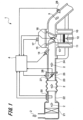
- FIG. 1 is a diagram showing a configuration example of an internal combustion engine control system provided with an air flow meter according to this embodiment.
- air 2 passes through an air cleaner 21, a main passage 22, a throttle body 23, and an intake manifold 24 based on the operation of an internal combustion engine 10 comprising engine cylinders 11 and engine pistons 12. , into the combustion chamber of the engine cylinder 11 .
- the main passage 22 is formed by the intake body.
- the air flow meter 20 is arranged in the middle of the main passage 22 .
- the air flow meter 20 is a device that measures the flow rate of the air 2 flowing through the main passage 22 . In this embodiment, the case where the air flow meter 20 is a thermal air flow meter will be described as an example.
- the fuel injection valve 14 injects a predetermined amount of fuel based on the air flow rate measured by the air flow meter 20 .
- the fuel and air are introduced into the combustion chamber via the intake valve 15 while being mixed with each other.
- the mixed gas of fuel and air led to the combustion chamber is explosively combusted by spark ignition of the spark plug 13 to generate mechanical energy.
- the gas after combustion is led to an exhaust pipe through an exhaust valve 16 and discharged out of the vehicle as exhaust gas 3 from the exhaust pipe.
- the flow rate of air led to the combustion chamber is controlled by the throttle valve 25.
- the opening of the throttle valve 25 changes according to the operation of an accelerator pedal (not shown).
- a throttle angle sensor 26 measures the opening of the throttle valve 25 .
- the rotation angle sensor 17 is a sensor for measuring the positions and states of the engine piston 12, the intake valve 15, and the exhaust valve 16, and for measuring the rotational speed of the internal combustion engine 10.
- the oxygen sensor 28 is a sensor for measuring the state of the mixture ratio between the amount of fuel and the amount of air from the state of the exhaust gas 3 .
- the control device 4 controls the fuel injection amount by the fuel injection valve 14 and the ignition timing by the spark plug 13 based on the measurement results of the air flow meter 20 and the rotation angle sensor 17 . Further, the control device 4 controls the amount of air bypassing the throttle valve 25 with the idle air control valve 27 when the internal combustion engine 10 is in an idling state.
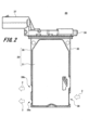
- FIG. 2 is a front view of the air flow meter according to this embodiment.
- the air flow meter 20 is attached to the main passage 22 in the direction shown in FIG. Defines direction and left-right direction.
- the air flow meter 20 includes a housing 30, a cover 31 attached to the housing 30, and a flow detection sensor 32 (see FIG. 3) housed in a space formed by the housing 30 and the cover 31. and have.
- a housing 29 of the air flow meter 20 is composed of a housing 30 and a cover 31 .
- the housing 30 has a rectangular housing body portion 35 in front view, a flange portion 36 formed on the upper end side of the housing body portion 35 , and a connector portion 37 projecting from the flange portion 36 .
- the cover 31 is attached to the housing body portion 35 of the housing 30 .
- a housing 29 consisting of a housing 30 and a cover 31 has one air inlet 38 and three air outlets 39a and 39b.
- the flange portion 36 is a portion for fixing the air flow meter 20 to the intake body forming the main passage 22 .
- the connector portion 37 is a portion for electrically connecting the air flow meter 20 to the control device 4 .
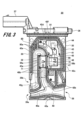
- FIG. 3 is a diagram showing a state in which the cover 31 of the air flow meter 20 shown in FIG. 2 is removed.
- the housing main body 35 is formed with a sub-passage 40 through which the air to be measured flows, and a circuit chamber 41 separated from the sub-passage 40 .
- the secondary passage 40 is a passage that connects the one air inlet 38 and the two air outlets 39a and 39b.
- the subpassage 40 has a first subpassage 40a and a second subpassage 40b.
- the first sub-passage 40 a and the second sub-passage 40 b are branched in the middle of the sub-passage 40 .
- the air outlet 39a opens at the end of the first sub-passage 40a
- the air outlet 39b opens at the end of the second sub-passage 40b
- the second sub-passage 40b is formed by bending into a U shape.
- a plurality of concave grooves 42a to 42g are formed in the housing body portion 35.
- a plurality of recessed grooves 42 a to 42 g are formed so as to surround the sub-passage 40 and circuit chamber 41 .
- the cover 31 is formed with a plurality of ridges (not shown) corresponding to the plurality of grooves 42a-42g.
- the plurality of recessed grooves 42a to 42g and the plurality of ridges fit together when the cover 31 is attached to the housing main body 35. As shown in FIG. Then, this fitting portion is hermetically sealed with a sealing material such as silicone resin.
- the circuit chamber 41 is formed adjacent to the second auxiliary passage 40b.
- a circuit board 43 is attached to the circuit chamber 41 .
- a portion 43a of the circuit board 43 is arranged to protrude from the circuit chamber 41 to the second auxiliary passage 40b.
- a flow rate detection sensor 32 and two pressure sensors 44 and 45 are mounted on the circuit board 43 . Both the flow rate detection sensor 32 and the respective pressure sensors 44 and 45 are configured by semiconductor packages.
- a protective layer 46 is formed on the circuit board 43 , and a sealing layer 47 is formed on the semiconductor package constituting the flow rate detection sensor 32 .
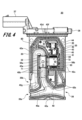
- FIG. 4 is a view of the air flow meter 20 shown in FIG. 3 in which the protective layer 46 and the sealing layer 47 are made transparent. As can be seen from FIG.
- the flow rate detection sensor 32 has a plurality of lead terminals 50. As shown in FIG. Also, the pressure sensor 44 has a plurality of lead terminals 48 and the pressure sensor 45 also has a plurality of lead terminals 49 .
- the flow rate detection sensor 32 and the respective pressure sensors 44 and 45 are configured by SOP (Small Outline Package), which is one form of semiconductor package.
- the flow rate detection sensor 32 and the pressure sensors 44 and 45 are both mounted on the circuit board 43 by soldering.
- the plurality of lead terminals 50 of the flow rate detection sensor 32 are soldered to a plurality of electrode portions (not shown) formed on the circuit board 43 corresponding to the mounting positions of the flow rate detection sensor 32.
- a plurality of lead terminals 48 of the pressure sensor 44 are soldered to a plurality of electrodes (not shown) formed on the circuit board 43
- a plurality of lead terminals 49 of the pressure sensor 45 are connected to the circuit board. It is soldered to a plurality of electrode portions (not shown) formed on 43 .
- the protective layer 46 is a layer for protecting the lead terminals 48 of the pressure sensor 44 , the lead terminals 49 of the pressure sensor 45 , and the lead terminals 50 of the flow rate detection sensor 32 .
- Protective layer 46 is formed of, for example, silicone resin.
- the sealing layer 47 is a layer for filling and sealing a gap formed between the semiconductor package and the cover 31 when the cover 31 is attached to the housing main body 35 .
- the sealing layer 47 is made of silicone resin, for example. 5 shows a structure in which the protrusion 31c of the cover 31 is fitted into the groove 42c of the housing main body 35, and the fitted portion is sealed with a sealing material 34 such as silicone resin. However, a similar sealing structure is also applied to the fitting portion between the groove and the ridge (not shown).
- FIG. 6 is a top view of the flow rate detection sensor 32
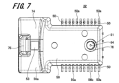
- FIG. 7 is a bottom view of the flow rate detection sensor 32
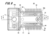
- FIG. 8 is a perspective view of the flow rate detection sensor 32 from the top side
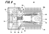
- FIG. 9 is a perspective view of the flow rate detection sensor 32 viewed from the bottom side.
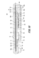
- 10 is a perspective view including a cross section taken along line AA of FIG. 8
- FIG. 11 is a perspective view including a cross section taken along line BB of FIG.
- the flow rate detection sensor 32 includes a lead frame 51, a plate 52 attached to the lead frame 51, a flow rate detection element 53 mounted on the lower surface of the plate 52, and the flow rate detection element 53.
- An LSI element 54 mounted on the lower surface of the plate 52 together with the detection element 53, a resin sheet 55 attached to the upper surface of the lead frame 51, a package section 56 for sealing the lead frame 51, the LSI element 54, etc. It has The flow rate detection element 53 and the LSI element 54 are semiconductor chips based on a semiconductor substrate such as silicon. LSI is an abbreviation for Large Scale Integration.
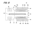
- FIG. 12 is a top view of the lead frame 51.
- the lead frame 51 has a plate-like portion 60 in addition to the plurality of lead terminals 50 described above. Each lead terminal 50 is bent into a gull-wing shape. The lower surface of the plate-like portion 60 is attached to the upper surface of the plate 52 described above.
- the plate 52 is a member for relieving stress due to the difference in linear expansion coefficients between the lead frame 51 and the flow rate detection element 53 and LSI element 54 .
- a through hole 52a (see FIG. 10) is formed in the plate 52 .
- the through hole 52 a communicates with the through hole 63 of the lead frame 51 and the recess 68 of the flow rate detecting element 53 .
- the plate 52 may be provided as required. Some lead terminals 50 of the plurality of lead terminals 50 are connected to the plate-like portion 60 , and the other lead terminals 50 are electrically connected to the LSI element 54 via bonding wires 65 . Also, the flow rate detection element 53 and the LSI element 54 are electrically connected via a bonding wire 66 (see FIG. 10).
- the bonding wires 65, 66 are composed of gold wires, for example.
- Two grooves 61 are formed on the upper surface of the plate-like portion 60 . Further, the plate-like portion 60 is formed with four punch holes 62 and two through holes 63 and 64 .
- the two grooves 61 correspond to ventilation passages leading to the recess 68 and are formed parallel to each other.
- the two grooves 61 are elongated along the longitudinal direction of the plate-like portion 60 (horizontal direction in FIG. 12). One end in the length direction of each groove 61 is curved in an arc and connected to a through hole 63 , and the other end in the length direction of each groove 61 is curved in an arc and connected to a through hole 64 . . Both of the through holes 63 and 64 are circular.
- the size of the through hole 64 is preferably set to a diameter of 0.3 mm or less so that foreign matter does not enter the groove 61 through the through hole 64 .
- the shape of the through-holes 63 and 64 is not limited to circular, and may be any shape such as polygonal.
- the flow rate detection element 53 has a diaphragm 67.
- the diaphragm 67 is formed by leaving a thin portion of the semiconductor substrate serving as the base of the flow rate detecting element 53 .
- the lower surface of the diaphragm 67 corresponds to the main surface of the diaphragm 67 and the upper surface of the diaphragm 67 corresponds to the rear surface of the diaphragm 67 .
- a flow rate detector (not shown) is formed on the lower surface of the diaphragm 67 .
- the flow rate detector is a portion that detects the flow rate of the air flowing through the second sub-passage 40 b of the sub-passage 40 .
- the flow rate detector is composed of, for example, a heating resistor and a pair of temperature measuring resistors.
- a concave portion 68 is formed on the upper surface side of the diaphragm 67 .
- the recess 68 forms a recessed space.
- the recess 68 is open on the side opposite to the diaphragm 67 and has an area larger than that of the diaphragm 67 .
- the flow rate detection element 53 is fixed to the plate 52 with an adhesive (not shown), and the LSI element 54 is also fixed to the plate 52 with an adhesive (not shown).
- the LSI element 54 controls the amount of heat generated by the resistor in the flow rate detection portion of the flow rate detection element 53 and outputs a signal representing the air flow rate detected by the flow rate detection portion to the outside via the lead terminal 50 .
- the resin sheet 55 is attached to the top surface of the lead frame 51 .
- the resin sheet 55 is a rectangular sheet elongated in the longitudinal direction of the flow rate detection sensor 32, and is made of polyimide tape, for example.
- the resin sheet 55 is attached to the lead frame 51 so as to cover the grooves 61 and the through holes 63 of the lead frame 51 .
- a circular through hole 70 (see FIGS. 8 and 10) is formed in the resin sheet 55 .
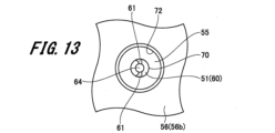
- FIG. 13 is an enlarged view of the C portion of FIG.
- the through hole 70 of the resin sheet 55 has a larger dimension than the through hole 64 of the lead frame 51 .
- the through holes 64 and 70 are arranged concentrically.
- the package portion 56 is obtained by molding a thermosetting resin into a predetermined shape, for example. As shown in FIGS. 6 and 7, the package portion 56 has a first package portion 56a and a second package portion 56b integrally formed with the first package portion 56a.
- the first package portion 56a is resin-sealed mainly on the flow rate detection element 53 side
- the second package portion 56b is mainly resin-sealed on the LSI element 54 side.
- the first package portion 56a is arranged in the second sub-passage 40b of the sub-passage 40
- the second package portion 56b is arranged in the circuit chamber 41 (see FIGS. 3 and 5).
- the first package portion 56a is formed wider than the second package portion 56b.
- the plurality of lead terminals 50 described above are arranged on two sides of the second package portion 56b.
- a first opening 71 is formed in the upper surface of the first package portion 56a, and a second opening 72 is formed in the upper surface of the second package portion 56b.
- the first opening 71 is circular in plan view, and the second opening 72 is also circular in plan view.
- the first opening 71 is formed in a trapezoidal cross section so that the diameter gradually increases toward the upper surface of the first package portion 56a, and the second opening 72 gradually increases toward the lower surface of the second package portion 56b. It is formed to have a trapezoidal cross section so that the diameter increases. As shown in FIG.
- the second opening 72 is larger than the through hole 70 of the resin sheet 55 . Also, the second opening 72 is arranged concentrically with the through hole 64 and the through hole 70 .
- a bank portion 73 (see FIGS. 5 and 6) is formed on the upper surface of the package portion 56 . The bank portion 73 is formed near the boundary between the first package portion 56a and the second package portion 56b. The aforementioned sealing layer 47 (FIG. 3) is arranged closer to the second package portion 56b than the bank portion 73 is.
- a ventilation part 74 is formed on the lower surface side of the package part 56 as shown in FIGS.
- the ventilation part 74 is a part for passing the air flowing through the second sub-passage 40 b of the sub-passage 40 .
- the ventilation part 74 is formed in a concave shape by thinning the thickness dimension of the first package part 56a except for the convex part 75 provided on the lower surface of the first package part 56a.
- the lower surface of the diaphragm 67 described above is arranged in a state of being exposed to the concave space of the ventilation portion 74 .
- a third opening 76 is formed in the lower surface of the second package portion 56b.
- the third opening 76 is formed to have a trapezoidal cross section so that the diameter gradually increases toward the lower surface of the second package portion 56b.
- the third opening 76 is arranged concentrically with the through hole 64 of the lead frame 51, as shown in FIG.
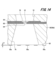
- FIG. 14 is an enlarged view of part D in FIG.
- the end portion 50a of the lead terminal 50 is arranged to protrude downward from the lower surface of the package portion 56 by a slight amount ⁇ t.
- a terminal portion 50 a of the lead terminal 50 is a portion to be soldered to an electrode portion of the circuit board 43 . Therefore, as shown in FIG. 5 , when the flow rate detection sensor 32 is mounted on the circuit board 43 , the package section 56 is slightly lifted from the circuit board 43 . Therefore, between the circuit board 43 and the package portion 56, a minute gap 77 is formed corresponding to the protrusion amount .DELTA.t. This gap 77 is a gap for ventilation that allows communication between the third opening 76 and the second sub-passage 40b.
- the periphery of the second package portion 56b is sealed with the protective layer 46 and the sealing layer 47, and a gap 77 is formed in this sealed region.
- the dimension of the gap 77 in the thickness direction of the package portion 56 is preferably set to a dimension that can prevent foreign matter flowing through the sub-passage 40 together with the air from entering the third opening 76 through the gap 77 .
- Foreign matter is, for example, water or dust.
- two grooves 61 are formed inside the package portion 56 as ventilation passages.
- One end of the groove 61 is connected to the recess 68 via the through hole 52a of the plate 52. As shown in FIG. That is, one end of the groove 61 communicates with the recess 68 via the through hole 52a.
- the other end of the groove 61 is connected to a through hole 64 as a branch. That is, the other end of groove 61 communicates with through hole 64 .
- the branching portion is a portion where the first ventilation path 81 and the second ventilation path 82 shown in FIG.
- the through hole 64 opens to both the second opening 72 and the third opening 76, as shown in FIGS.
- the second opening 72 forms part of the first ventilation path 81 and the third opening 76 forms part of the second ventilation path 82 .
- the first ventilation path 81 and the second ventilation path 82 are formed using two grooves 61 formed in the lead frame 51 as ventilation paths. Also, the first ventilation path 81 and the second ventilation path 82 are branched into one and the other from a through hole 64 as a branch portion formed in the lead frame 51 . That is, the first ventilation path 81 and the second ventilation path 82 are paths different from each other. Specifically, the first ventilation path 81 communicates with the circuit chamber 41 from the through hole 64 through the second opening 72, and further from the circuit chamber 41 through the ventilation section 80 (see FIGS. 3 and 4) to the second ventilation path 81. It communicates with the secondary passage 40b. Pressure sensors 44 and 45 are arranged in the middle of the first ventilation path 81 . On the other hand, the second ventilation path 82 communicates from the through hole 64 through the third opening 76 to the gap 77, and communicates through the gap 77 to the second sub-passage 40b.
- the ventilation part 80 is a part that ventilates the second sub-passage 40b and the circuit chamber 41 at a position away from the second package part 56b. As shown in FIG. 3, the ventilation part 80 is formed so as to communicate the second sub-passage 40b and the circuit chamber 41 at a bent portion (folded portion) of the second sub-passage 40b.
- the ventilation section 80 is configured by an introduction passage including a plurality of ventilation sections 80a. As for the introduction passage, it is preferable to employ a configuration similar to that of the "pressure introduction passage" described in Japanese Patent Application Laid-Open No. 2021-67510. However, the configuration of the introduction passage may adopt a configuration different from the "pressure introduction passage" described in the above publication.
- the two grooves 61 form the ventilation passage inside the package portion 56, and the secondary passage 40 (second It has a first ventilation path 81 and a second ventilation path 82 communicating with the secondary passage 40b). Also, the first ventilation path 81 and the second ventilation path 82 are formed as follows.
- the first ventilation path 81 includes a through hole 52a formed in the plate 52, a groove 61 connected at one end to the through hole 52a, a through hole 64 connected to the other end of the groove 61, and a through hole 64 connected to the other end of the groove 61. It is formed so as to pass through a second opening 72 that exposes the hole 64, the circuit chamber 41, and a ventilation section 80 that communicates the circuit chamber 41 with the second auxiliary passage 40b.
- the second ventilation path 82 includes a through hole 52a formed in the plate 52, a groove 61 connected at one end to the through hole 52a, a through hole 64 connected to the other end of the groove 61, and a through hole 64 connected to the other end of the groove 61. It is formed so as to pass through a third opening 76 that exposes the hole 64 and a gap 77 that communicates with the third opening 76 .
- the recessed portion 68 on the back side of the diaphragm 67 communicates with the sub-passage 40 (second sub-passage 40b) through the two ventilation paths 81 and 82 using the groove 61 as the ventilation path. Therefore, according to the air flow meter 20 according to the present embodiment, compared to the case where only one ventilation path connecting the recess 68 and the sub-passage 40 is formed as described in Patent Document 1, , the ventilation performance (ventilation efficiency) between the recess 68 and the sub-passage 40 can be enhanced.
- the pressure in the space within the recess 68 can be quickly brought close to the pressure in the space within the sub-passage 40. .
- the pressure in the space on the main surface side and the back surface side of the diaphragm 67 can be maintained evenly, and deformation of the diaphragm 67 can be effectively suppressed. Therefore, it is possible to suppress the characteristic fluctuation of the flow rate detection sensor 32 due to the deformation of the diaphragm 67 and improve the measurement accuracy of the air flow rate.
- one end of the groove 61 forming the ventilation passage is connected to the recess 68, and the other end of the groove 61 is connected to the through hole 64 as a branch.
- the first ventilation path 81 and the second ventilation path 82 can be branched at a position close to the recess 68 while preventing foreign matter from entering the recess 68 with the groove 61 . Therefore, even if pressure fluctuation occurs in the space within the sub passage 40, the pressure in the space within the recess 68 can be quickly changed according to this pressure fluctuation. Therefore, deformation of the diaphragm 67 can be suppressed more effectively.
- the branch portion by configuring the branch portion with the through hole 64, the circuit chamber 41 in which the second package portion 56b is arranged and the third opening portion 76 provided in the second package portion 56b are A state of communication is established through the through hole 64 . Therefore, compared to the case where the first ventilation path 81 and the second ventilation path 82 are branched by a non-through hole (not shown), the air resistance of the entire ventilation path can be reduced. Moreover, the space in the circuit chamber 41 and the space in the third opening 76 can be maintained at a uniform pressure. Therefore, the interaction between the first ventilation path 81 and the second ventilation path 82 can effectively suppress the pressure difference between the recess 68 and the sub-passage 40 .
- the ventilation performance between the sub-passage 40 and the circuit chamber 41 is improved, so the first ventilation path
- the pressure sensors 44 and 45 in the middle of 81, the accuracy and responsiveness of the pressure sensors 44 and 45 can be improved.
- the first ventilation path 81 includes a ventilation part 80 that ventilates the sub-passage 40 and the circuit room 41 at a position away from the second package part 56b
- the second ventilation path 82 is It includes a ventilation gap 77 formed between the package portion 56 and the circuit board 43 .
- the length of the second ventilation path 82 becomes shorter than the length of the first ventilation path 81 . Therefore, by forming the second ventilation path 82 in addition to the first ventilation path 81 , the pressure in the recess 68 can quickly follow the pressure fluctuations on the main surface side of the diaphragm 67 .
- a ventilation gap 77 is formed wide in the depth direction of FIG. Therefore, the second sub-passage 40b and the third opening 76 can be maintained at a uniform pressure.
- the present invention is not limited to the above-described embodiments, and includes various modifications.
- the details of the present invention have been described for easy understanding, but the present invention is not necessarily limited to having all the configurations described in the above-described embodiments.
- part of the configuration of one embodiment can be replaced with the configuration of another embodiment.
- add the configuration of another embodiment to the configuration of one embodiment.
- the air flow meter 20 has two ventilation paths 81 and 82, but the air flow meter 20 may have three or more ventilation paths.
- one of the plurality of ventilation paths may be formed through, for example, a ventilation groove formed in the sealing layer 47 .
- the ventilation passage is formed by two grooves 61, but the number of grooves 61 may be one, or three or more.
Landscapes
- Physics & Mathematics (AREA)
- Fluid Mechanics (AREA)
- General Physics & Mathematics (AREA)
- Measuring Volume Flow (AREA)
Abstract
Description
本願は、上記課題を解決する手段を複数含んでいるが、その一つを挙げるならば、計測対象の空気が流れる副通路と、副通路と区画された回路室とを有する筐体と、副通路を流れる空気の流量を検出する流量検出部が主面に形成されたダイアフラムと、ダイアフラムの裏面側に形成された凹部と、ダイアフラムを露出する状態に配置してなる第1パッケージ部及び該第1パッケージ部と一体構造をなす第2パッケージ部を有するパッケージ部とを有し、第1パッケージ部が副通路に配置され、第2パッケージ部が回路室に配置された流量検出センサと、を備える空気流量計である。パッケージ部の内部には、凹部につながる通気通路が形成され、凹部は、通気通路を介して副通路に連通する第1の換気経路と、通気通路を介して第1の換気経路とは異なる経路で副通路に連通する第2の換気経路と、を少なくとも含む複数の換気経路を介して副通路に連通している。
上記した以外の課題、構成及び効果は、以下の実施形態の説明によって明らかにされる。
図1は、本実施形態に係る空気流量計を備える内燃機関制御システムの構成例を示す図である。
図1に示す内燃機関制御システム1において、空気2は、エンジンシリンダ11とエンジンピストン12を備える内燃機関10の動作に基づき、エアクリーナ21、主通路22、スロットルボディ23、及び、吸気マニホールド24を経て、エンジンシリンダ11の燃焼室に導かれる。主通路22は、吸気ボディによって形成されている。空気流量計20は、主通路22の途中に配置されている。空気流量計20は、主通路22を流れる空気2の流量を計測する機器である。本実施形態においては、空気流量計20が熱式空気流量計である場合を例に挙げて説明する。
図2は、本実施形態に係る空気流量計の正面図である。なお、本実施形態においては、空気流量計20が図2に示す向きで主通路22に取り付けられ、この主通路22を空気2が矢印方向に流れる場合を想定して、空気流量計20の上下方向及び左右方向を規定する。
図3に示すように、ハウジング本体部35には、計測対象の空気が流れる副通路40と、この副通路40と区画された回路室41とが形成されている。副通路40は、上述した1つの空気導入口38と2つの空気導出口39a,39bとをつなぐ通路である。副通路40は、第1副通路40aと第2副通路40bとを有している。第1副通路40aと第2副通路40bは、副通路40の途中で分岐している。
続いて、流量検出センサ32の構成について詳しく説明する。なお、流量検出センサ32の構成を説明するにあたっては、図5において、カバー31と対面する側を流量検出センサ32の上面側、回路基板43と対面する側を流量検出センサ32の下面側とする。
図12に示すように、リードフレーム51は、前述した複数のリード端子50の他に、板状部60を有している。各々のリード端子50は、ガルウィング形状に曲げられている。板状部60の下面は、上述したプレート52の上面に貼り付けられている。プレート52は、リードフレーム51と流量検出素子53,LSI素子54との線膨張係数差による応力を緩和するための部材である。プレート52には貫通孔52a(図10参照)が形成されている。貫通孔52aは、リードフレーム51の貫通孔63と流量検出素子53の凹部68とに連通している。連通とは、空間的につながることを意味する用語である。プレート52は、必要に応じて設けるようにすればよい。複数のリード端子50のうち、一部のリード端子50は板状部60につながっており、他のリード端子50はボンディングワイヤ65を介してLSI素子54に電気的に接続されている。また、流量検出素子53とLSI素子54は、ボンディングワイヤ66(図10参照)を介して電気的に接続されている。ボンディングワイヤ65,66は、たとえば金ワイヤによって構成される。
図13に示すように、樹脂シート55の貫通孔70は、リードフレーム51の貫通孔64よりも大きな寸法で開口している。貫通孔64と貫通孔70は、同心円状に配置されている。
図14に示すように、リード端子50の末端部50aは、パッケージ部56の下面よりも僅かな量Δtだけ下方に突出して配置されている。リード端子50の末端部50aは、回路基板43の電極部にハンダ付けされる部分である。したがって、図5に示すように、回路基板43に流量検出センサ32を実装した状態では、パッケージ部56が回路基板43から僅かに浮いた状態になる。このため、回路基板43とパッケージ部56との間には、上記の突出量Δtに対応する微小な隙間77が形成される。この隙間77は、第3開口部76と第2副通路40bとを連通させる換気用の隙間である。回路室41においては、第2パッケージ部56bの周囲が保護層46と封止層47とによって封止され、この封止された領域内に隙間77が形成されている。パッケージ部56の厚み方向における隙間77の寸法は、副通路40を空気と共に流れる異物が、この隙間77を通して第3開口部76に侵入することを抑制できる程度の寸法に設定するとよい。異物は、たとえば水や塵埃などである。
換気部80は、第2パッケージ部56bから離れた位置で第2副通路40bと回路室41とを換気する部分である。換気部80は、図3に示すように、第2副通路40bの曲がり部分(折り返し部分)で第2副通路40bと回路室41とを連通するように形成されている。換気部80は、複数の通気部80aを含む導入通路によって構成されている。導入通路については、好ましくは、特開2021-67510号公報に記載された「圧力導入通路」と同様の構成を採用するとよい。ただし、導入通路の構成は、上記公開特許公報に記載された「圧力導入通路」と異なる構成を採用してもかまわない。
このため、本実施形態に係る空気流量計20によれば、上記特許文献1に記載されているように凹部68と副通路40とをつなぐ換気経路が1つしか形成されていない場合に比べて、凹部68と副通路40との間の換気性能(換気効率)を高めることができる。したがって、たとえば副通路40を所定量以上の空気が流れて副通路40が負圧となった場合でも、凹部68内の空間の圧力を、副通路40内の空間の圧力に素早く近づけることができる。その結果、ダイアフラム67の主面側と裏面側で空間の圧力を均等に維持し、ダイアフラム67の変形を有効に抑制することができる。よって、ダイアフラム67の変形にともなう流量検出センサ32の特性変動を抑えて、空気流量の計測精度を高めることができる。また、上記特許文献1に記載された技術では、圧力導入通路の構造を工夫することにより、副通路40(第2副通路40b)から回路室41への異物の侵入を防いでいる。このため、たとえば凹部68と副通路40との間の換気性能を高めるために、換気導入通路の導入口の断面積を大きく確保すると、副通路40から回路室41に異物が侵入しやすくなる。この点、本実施形態に係る空気流量計20では、凹部68と副通路40とを2つの換気経路81,82でつないでいるため、換気部80における導入口の断面積を大きくしなくても、換気性能を高めることができる。よって、副通路40から回路室41への異物の侵入を抑制することができる。
なお、本発明は、上述した実施形態に限定されるものではなく、様々な変形例を含む。たとえば、上述した実施形態では、本発明の内容を理解しやすいように詳細に説明しているが、本発明は、上述した実施形態で説明したすべての構成を必ずしも備えるものに限定されない。また、ある実施形態の構成の一部を、他の実施形態の構成に置き換えることが可能である。また、ある実施形態の構成に他の実施形態の構成を加えることも可能である。また、各実施形態の構成の一部について、これを削除し、又は他の構成を追加し、あるいは他の構成に置換することも可能である。
Claims (5)
- 計測対象の空気が流れる副通路と、前記副通路と区画された回路室とを有する筐体と、
前記副通路を流れる空気の流量を検出する流量検出部が主面に形成されたダイアフラムと、前記ダイアフラムの裏面側に形成された凹部と、前記ダイアフラムを露出する状態に配置してなる第1パッケージ部及び該第1パッケージ部と一体構造をなす第2パッケージ部を有するパッケージ部とを有し、前記第1パッケージ部が前記副通路に配置され、前記第2パッケージ部が前記回路室に配置された流量検出センサと、
を備える空気流量計であって、
前記パッケージ部の内部には、前記凹部につながる通気通路が形成され、
前記凹部は、前記通気通路を介して前記副通路に連通する第1の換気経路と、前記通気通路を介して前記第1の換気経路とは異なる経路で前記副通路に連通する第2の換気経路と、を少なくとも含む複数の換気経路を介して前記副通路に連通している
空気流量計。 - 前記通気通路の一端部は前記凹部に接続され、前記通気通路の他端部は、前記第1の換気経路と前記第2の換気経路とが分岐する分岐部に接続されている
請求項1に記載の空気流量計。 - 前記分岐部は、貫通孔によって構成されている
請求項2に記載の空気流量計。 - 前記第1の換気経路の途中に圧力センサが配置されている
請求項1に記載の空気流量計。 - 前記流量検出センサが実装される回路基板をさらに備え、
前記第1の換気経路は、前記第2パッケージ部から離れた位置で前記副通路と前記回路室とを換気する換気部を含み、
前記第2の換気経路は、前記パッケージ部と前記回路基板との間に形成される換気用の隙間を含む
請求項1に記載の空気流量計。
Priority Applications (5)
| Application Number | Priority Date | Filing Date | Title |
|---|---|---|---|
| US18/703,575 US20260085956A1 (en) | 2021-10-26 | 2021-10-26 | Air flow meter |
| PCT/JP2021/039381 WO2023073791A1 (ja) | 2021-10-26 | 2021-10-26 | 空気流量計 |
| JP2023555916A JP7629537B2 (ja) | 2021-10-26 | 2021-10-26 | 空気流量計 |
| CN202180103048.3A CN118076861A (zh) | 2021-10-26 | 2021-10-26 | 空气流量计 |
| DE112021008116.0T DE112021008116T5 (de) | 2021-10-26 | 2021-10-26 | Luftströmungsmesser |
Applications Claiming Priority (1)
| Application Number | Priority Date | Filing Date | Title |
|---|---|---|---|
| PCT/JP2021/039381 WO2023073791A1 (ja) | 2021-10-26 | 2021-10-26 | 空気流量計 |
Publications (1)
| Publication Number | Publication Date |
|---|---|
| WO2023073791A1 true WO2023073791A1 (ja) | 2023-05-04 |
Family
ID=86159219
Family Applications (1)
| Application Number | Title | Priority Date | Filing Date |
|---|---|---|---|
| PCT/JP2021/039381 Ceased WO2023073791A1 (ja) | 2021-10-26 | 2021-10-26 | 空気流量計 |
Country Status (5)
| Country | Link |
|---|---|
| US (1) | US20260085956A1 (ja) |
| JP (1) | JP7629537B2 (ja) |
| CN (1) | CN118076861A (ja) |
| DE (1) | DE112021008116T5 (ja) |
| WO (1) | WO2023073791A1 (ja) |
Citations (2)
| Publication number | Priority date | Publication date | Assignee | Title |
|---|---|---|---|---|
| WO2015033589A1 (ja) * | 2013-09-05 | 2015-03-12 | 日立オートモティブシステムズ株式会社 | 流量センサおよび流量センサ装置 |
| WO2020202791A1 (ja) * | 2019-03-29 | 2020-10-08 | 日立オートモティブシステムズ株式会社 | 物理量検出装置 |
Family Cites Families (3)
| Publication number | Priority date | Publication date | Assignee | Title |
|---|---|---|---|---|
| JP5738818B2 (ja) | 2012-09-28 | 2015-06-24 | 日立オートモティブシステムズ株式会社 | 熱式流量計 |
| JP6965358B2 (ja) | 2017-09-05 | 2021-11-10 | 日立Astemo株式会社 | 熱式流量計 |
| JP2021067510A (ja) | 2019-10-21 | 2021-04-30 | 日立Astemo株式会社 | 物理量検出装置 |
-
2021
- 2021-10-26 JP JP2023555916A patent/JP7629537B2/ja active Active
- 2021-10-26 DE DE112021008116.0T patent/DE112021008116T5/de active Pending
- 2021-10-26 WO PCT/JP2021/039381 patent/WO2023073791A1/ja not_active Ceased
- 2021-10-26 CN CN202180103048.3A patent/CN118076861A/zh active Pending
- 2021-10-26 US US18/703,575 patent/US20260085956A1/en active Pending
Patent Citations (2)
| Publication number | Priority date | Publication date | Assignee | Title |
|---|---|---|---|---|
| WO2015033589A1 (ja) * | 2013-09-05 | 2015-03-12 | 日立オートモティブシステムズ株式会社 | 流量センサおよび流量センサ装置 |
| WO2020202791A1 (ja) * | 2019-03-29 | 2020-10-08 | 日立オートモティブシステムズ株式会社 | 物理量検出装置 |
Also Published As
| Publication number | Publication date |
|---|---|
| CN118076861A (zh) | 2024-05-24 |
| JPWO2023073791A1 (ja) | 2023-05-04 |
| JP7629537B2 (ja) | 2025-02-13 |
| DE112021008116T5 (de) | 2024-07-04 |
| US20260085956A1 (en) | 2026-03-26 |
Similar Documents
| Publication | Publication Date | Title |
|---|---|---|
| US6516785B1 (en) | Air flow sensor | |
| JP2010151795A (ja) | 熱式空気流量センサ | |
| JPWO2019049513A1 (ja) | 熱式流量計 | |
| WO2017056699A1 (ja) | 物理量検出装置 | |
| JP6181900B2 (ja) | 空気流量検出装置 | |
| JP7074928B2 (ja) | 物理量検出装置 | |
| JPWO2018100854A1 (ja) | 空気流量測定装置 | |
| JP7399348B2 (ja) | 流量測定装置 | |
| JP7629537B2 (ja) | 空気流量計 | |
| WO2017056700A1 (ja) | 物理量検出装置 | |
| JP2016194465A (ja) | 物理量検出素子 | |
| JPWO2019064886A1 (ja) | 物理量検出装置 | |
| JP7127441B2 (ja) | 物理量計測装置及び流量計測装置 | |
| US11927466B2 (en) | Physical quantity measurement device including a thermal flow rate sensor with a ventilation flow path | |
| JP2021067510A (ja) | 物理量検出装置 | |
| JP7629112B2 (ja) | 物理量検出装置 | |
| WO2022209268A1 (ja) | 物理量計測装置 | |
| JP6453790B2 (ja) | 物理量検出装置 | |
| JP7765655B2 (ja) | 流量センサ | |
| JP6775629B2 (ja) | 物理量検出素子 | |
| CN115176130B (zh) | 空气流量测定装置 | |
| JP2020112433A (ja) | 物理量検出装置 | |
| KR20260065275A (ko) | 가스 감지 소자 및 이를 이용한 가스 감지 센서 | |
| JPWO2020202721A1 (ja) | 物理量測定装置 | |
| WO2019064908A1 (ja) | 物理量検出装置 |
Legal Events
| Date | Code | Title | Description |
|---|---|---|---|
| 121 | Ep: the epo has been informed by wipo that ep was designated in this application |
Ref document number: 21962341 Country of ref document: EP Kind code of ref document: A1 |
|
| ENP | Entry into the national phase |
Ref document number: 2023555916 Country of ref document: JP Kind code of ref document: A |
|
| WWE | Wipo information: entry into national phase |
Ref document number: 202180103048.3 Country of ref document: CN |
|
| 122 | Ep: pct application non-entry in european phase |
Ref document number: 21962341 Country of ref document: EP Kind code of ref document: A1 |